54
ASSEMBLY AND OPERATION MANUAL RTD-16 Full Height Rotor Turnstile
ASSEMBLY AND OPERATION MANUAL
RTD-16Full Height Rotor Turnstile
Full Height Rotor Turnstile
RTD-16
Assembly and Operation Manual
CONTENT
1 APPLICATION ............................................................................................................. 3
2 OPERATION CONDITIONS ........................................................................................ 3 3 TECHNICAL SPECIFICATIONS ................................................................................. 4
4 DELIVERY SET ........................................................................................................... 5 4.1 Standard delivery set ............................................................................................. 5 4.2 Optional equipment and installation tools .............................................................. 6
5 DESIGN AND OPERATION ........................................................................................ 8 5.1 Main features ......................................................................................................... 8
5.2 Design of the turnstile ............................................................................................ 9 5.3 Control of the turnstile ......................................................................................... 13
5.3.1 The remote control panel .............................................................................. 13 5.3.2 Control modes .............................................................................................. 14 5.3.3 Logic operational sequence in the pulse operation mode ............................. 14
5.3.4 Parameters of control signals ....................................................................... 15
5.3.5 Operation from the RC-panel ........................................................................ 16 5.3.6 Fire Alarm device .......................................................................................... 17
5.3.7 Operation via an ACS-controller ................................................................... 17 5.4 Optional devices that can be connected to the turnstile ...................................... 18
5.4.1 Signal parameters of relay outputs ............................................................... 18 5.4.2 Intrusion detector and siren .......................................................................... 18
5.4.3 Remote light indicators ................................................................................. 19 5.5 Operational contingencies and feedback ............................................................. 19
6 MARKING AND PACKAGING ................................................................................... 21 7 SAFETY REQUIREMENTS ....................................................................................... 22
7.1 Installation safety requirements ........................................................................... 22
7.2 Operational safety requirements .......................................................................... 22 8 INSTALLATION ......................................................................................................... 23
8.1 General recommendations .................................................................................. 23
8.2 Tools and equipment required for assembly ........................................................ 24
8.3 Allowable cable lengths ....................................................................................... 24 8.4 Turnstile and optional equipment connection layout ............................................ 25
8.5 Installation of the turnstile .................................................................................... 26 8.6 Selection of the passage mode ........................................................................... 34 8.7 Adjustment of damper device RTD-16.2 .............................................................. 35
8.7.1 The damper device operation check ............................................................. 35 8.7.2 The damper device adjustment order ........................................................... 36
8.8 The turnstile performance check ......................................................................... 37 8.8.1 Verification of the mechanical and emergency unblocking of the turnstile .... 37
8.8.2 Verification of the turnstile performance in test mode ................................... 37 9 OPERATING THE TURNSTILE ................................................................................ 40
9.1 Starting procedure ............................................................................................... 40
9.2 Pulse control mode .............................................................................................. 40 9.3 Potential control mode ......................................................................................... 43 9.4 Emergency actions. ............................................................................................. 43 9.5 Troubleshooting ................................................................................................... 44
10 MAINTENANCE ........................................................................................................ 45 11 TRANSPORTATION AND STORAGE ...................................................................... 47 APPENDIX 1. Algorithm of control signals generation in pulse control mode .................... 48 APPENDIX 2. Algorithm of control signals generation in potential control mode. .............. 49 APPENDIX 3. The markup schemes for joint installation
of checkpoint components and RTD-16...................................................... 50
RTD-16 Full Height Rotor Turnstile
3
Dear customers!
Thank you for purchasing the PERCo product. Please follow instructions given in this Manual carefully, and this quality product
will provide many years of trouble-free use.
The Assembly and Operation Manual (hereinafter – the Manual) contains the instructions you will need for safe transportation, storage, installation, operation and maintenance of the RTD-16 full height rotor turnstile.
Abbreviations adopted in the Manual: ID – intrusion detector; PS – power supply; WD – walkway downlights; RC-panel – remote control panel; WRC – wireless remote control; ACS – access control system.
1 APPLICATION
The RTD-16 full height rotor turnstile (hereinafter – the turnstile) is a form of rotor gate designed for management of pedestrian flows and access control at entrance points of facilities and areas with high security requirements and necessity for full closure of the passageway.
Available versions of the turnstile:
RTD-16.1 – model with motorized drive;
RTD-16.2 – model with mechanical drive.
RTD-16.1S and RTD-16.2S are equipped with the rotor made of stainless steel.
It is advisable to determine the number of turnstiles necessary for providing fast and convenient pedestrian passage on the basis of the corresponding throughput (see Section 3).
2 OPERATION CONDITIONS
The turnstile with regard to resistance to environmental exposure complies with GOST 15150-69, category N2 (outdoor operation).
Operation of the turnstile is allowed at ambient temperature from – 40ºC to +50°C (under shelter – to +55°C) and at relative air humidity of up to 98% at +25°C.
The RC-panel with regard to resistance to environmental exposure complies with GOST 15150-69, category NF4 (operation in premises with climate control).
Operation of the RC-panel is allowed at ambient air temperature from +1°C to +40°C and at relative humidity of up to 80% at +25°C.
Operation manual
4
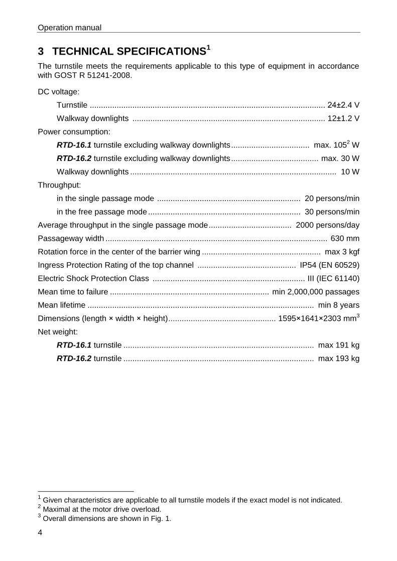
3 TECHNICAL SPECIFICATIONS1
The turnstile meets the requirements applicable to this type of equipment in accordance with GOST R 51241-2008.
DC voltage:
Turnstile ......................................................................................................... 24±2.4 V
Walkway downlights ...................................................................................... 12±1.2 V
Power consumption:
RTD-16.1 turnstile excluding walkway downlights ................................... max. 1052 W
RTD-16.2 turnstile excluding walkway downlights ....................................... max. 30 W
Walkway downlights ............................................................................................ 10 W
Throughput:
in the single passage mode ................................................................ 20 persons/min
in the free passage mode .................................................................... 30 persons/min
Average throughput in the single passage mode ..................................... 2000 persons/day
Passageway width ................................................................................................... 630 mm
Rotation force in the center of the barrier wing ..................................................... max 3 kgf
Ingress Protection Rating of the top channel ............................................ IP54 (EN 60529)
Electric Shock Protection Class .................................................................... III (IEC 61140)
Mean time to failure ....................................................................... min 2,000,000 passages
Mean lifetime ..................................................................................................... min 8 years
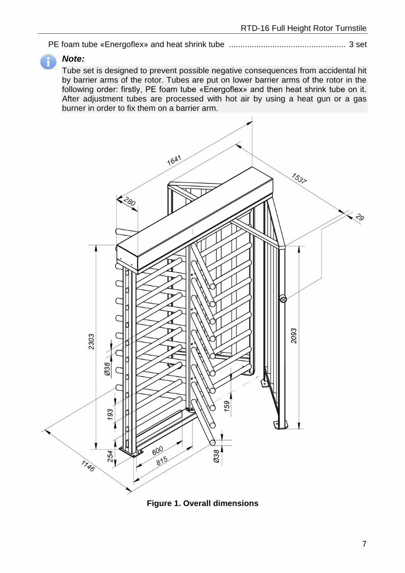
Dimensions (length × width × height) ................................................ 1595×1641×2303 mm3
Net weight:
RTD-16.1 turnstile ..................................................................................... max 191 kg
RTD-16.2 turnstile ..................................................................................... max 193 kg
1 Given characteristics are applicable to all turnstile models if the exact model is not indicated.
2 Maximal at the motor drive overload.
3 Overall dimensions are shown in Fig. 1.
RTD-16 Full Height Rotor Turnstile
5
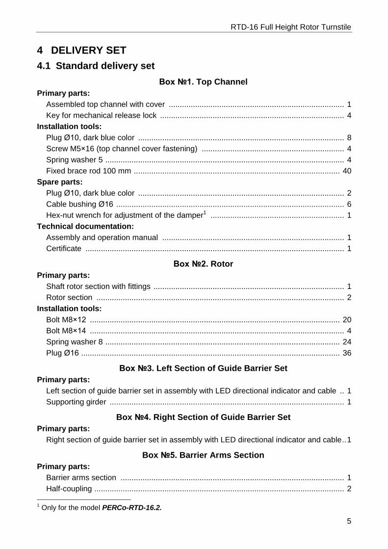
4 DELIVERY SET
4.1 Standard delivery set
Box №1. Top Channel
Primary parts:
Assembled top channel with cover ................................................................................ 1
Key for mechanical release lock .................................................................................... 4
Installation tools:
Plug Ø10, dark blue color .............................................................................................. 8
Screw M5×16 (top channel cover fastening) ................................................................. 4
Spring washer 5 ............................................................................................................. 4
Fixed brace rod 100 mm .............................................................................................. 40
Spare parts:
Plug Ø10, dark blue color .............................................................................................. 2
Cable bushing Ø16 ........................................................................................................ 6
Hex-nut wrench for adjustment of the damper1 ............................................................. 1
Technical documentation:
Assembly and operation manual ................................................................................... 1
Certificate ...................................................................................................................... 1
Box №2. Rotor
Primary parts:
Shaft rotor section with fittings ....................................................................................... 1
Rotor section ................................................................................................................. 2
Installation tools:
Bolt M8×12 .................................................................................................................. 20
Bolt M8×14 .................................................................................................................... 4
Spring washer 8 ........................................................................................................... 24
Plug Ø16 ...................................................................................................................... 36
Box №3. Left Section of Guide Barrier Set
Primary parts:
Left section of guide barrier set in assembly with LED directional indicator and cable .. 1
Supporting girder ........................................................................................................... 1
Box №4. Right Section of Guide Barrier Set
Primary parts:
Right section of guide barrier set in assembly with LED directional indicator and cable .. 1
Box №5. Barrier Arms Section
Primary parts:
Barrier arms section ...................................................................................................... 1
Half-coupling .................................................................................................................. 2
1 Only for the model PERCo-RTD-16.2.
Operation manual
6
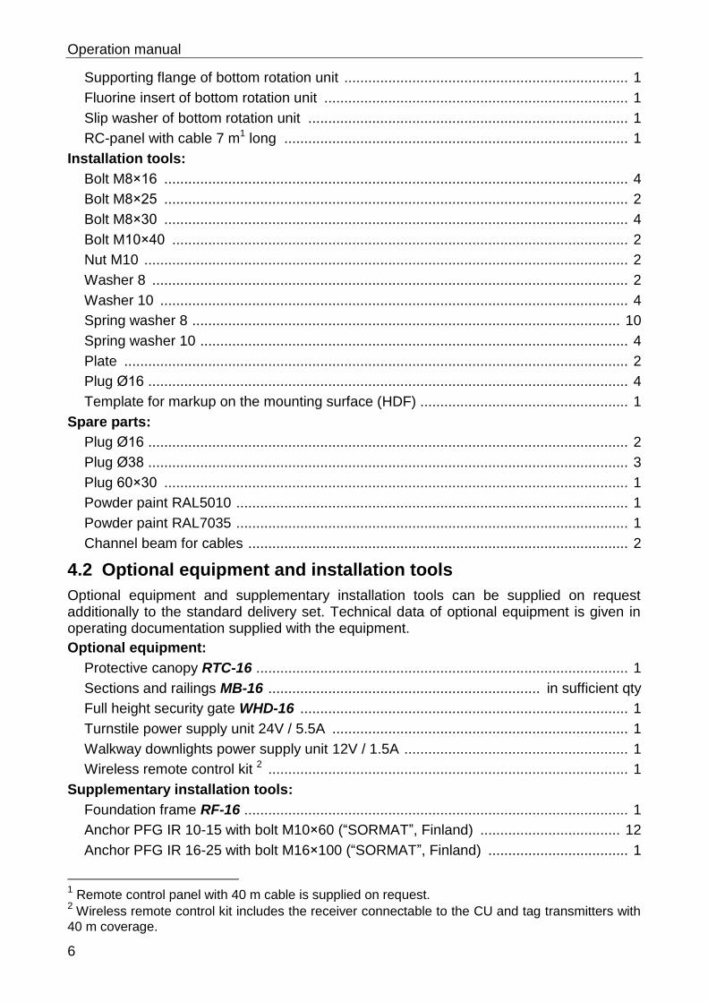
Supporting flange of bottom rotation unit ....................................................................... 1
Fluorine insert of bottom rotation unit ............................................................................ 1
Slip washer of bottom rotation unit ................................................................................ 1
RC-panel with cable 7 m1 long ...................................................................................... 1
Installation tools:
Bolt M8×16 .................................................................................................................... 4
Bolt M8×25 .................................................................................................................... 2
Bolt M8×30 .................................................................................................................... 4
Bolt M10×40 .................................................................................................................. 2
Nut M10 ......................................................................................................................... 2
Washer 8 ....................................................................................................................... 2
Washer 10 ..................................................................................................................... 4
Spring washer 8 ........................................................................................................... 10
Spring washer 10 ........................................................................................................... 4
Plate .............................................................................................................................. 2
Plug Ø16 ........................................................................................................................ 4
Template for markup on the mounting surface (HDF) .................................................... 1
Spare parts:
Plug Ø16 ........................................................................................................................ 2
Plug Ø38 ........................................................................................................................ 3
Plug 60×30 .................................................................................................................... 1
Powder paint RAL5010 .................................................................................................. 1
Powder paint RAL7035 .................................................................................................. 1
Channel beam for cables ............................................................................................... 2
4.2 Optional equipment and installation tools
Optional equipment and supplementary installation tools can be supplied on request additionally to the standard delivery set. Technical data of optional equipment is given in operating documentation supplied with the equipment.
Optional equipment:
Protective canopy RTC-16 ............................................................................................. 1
Sections and railings MB-16 .................................................................... in sufficient qty
Full height security gate WHD-16 .................................................................................. 1
Turnstile power supply unit 24V / 5.5A .......................................................................... 1
Walkway downlights power supply unit 12V / 1.5A ........................................................ 1
Wireless remote control kit 2 .......................................................................................... 1
Supplementary installation tools:
Foundation frame RF-16 ................................................................................................ 1
Anchor PFG IR 10-15 with bolt M10×60 (“SORMAT”, Finland) ................................... 12
Anchor PFG IR 16-25 with bolt M16×100 (“SORMAT”, Finland) ................................... 1
1 Remote control panel with 40 m cable is supplied on request.
2 Wireless remote control kit includes the receiver connectable to the CU and tag transmitters with
40 m coverage.
RTD-16 Full Height Rotor Turnstile
7
PE foam tube «Energoflex» and heat shrink tube ................................................... 3 set
Note:
Tube set is designed to prevent possible negative consequences from accidental hit by barrier arms of the rotor. Tubes are put on lower barrier arms of the rotor in the following order: firstly, PE foam tube «Energoflex» and then heat shrink tube on it. After adjustment tubes are processed with hot air by using a heat gun or a gas burner in order to fix them on a barrier arm.
Figure 1. Overall dimensions
Operation manual
8
5 DESIGN AND OPERATION
5.1 Main features
There are two options of the turnstile use – as a standalone unit operated from either RC-panel or wireless remote control, or as part of various identification and access control systems operated automatically via external ACS-controller.
The turnstile is a normally closed unit. When the power supply is off the rotor barrier wings are locked in closed position.
Combined coating of all turnstile elements with zinc and powder paint ensures high corrosion resistance and long years of service in harsh environments; the turnstile versions bearing “S”-marking in the index have the rotor with sections made of stainless steel.
High durability of polymeric powder coating keeps the elegant appearance intact in intensive use conditions.
For a more comfortable passage RTD-16.1 model includes an electric gear motor providing an automatic rotation of the rotor. RTD-16.2 model includes mechanic reset drive that allows automatic rotation of the rotor until the rotor is in the home position.
Additional installation of an intrusion detector or a siren provides a possibility for sound alarm on unauthorized attempts of passage.
The turnstile has built-in LED directional indicators for each passage direction, there is a possibility of optional installation of remote light indicators.
Use of lock-chamber – special space in the construction of the turnstile – allows providing the site with intense access control.
The turnstile is fit for installation on soft ground by means of a specially designed foundation frame RF-16.
For protection from environmental exposure and providing an extra barrier against climbing over the turnstile design enables installation of RTC-16 protective canopy that can be optionally included in the delivery set.
The turnstile design enables assembly together with WHD-16 full height gate that can be optionally included in the delivery set and can be used for providing an emergency or escape passage with a remote control and for carrying bulky cargo through the control area.
For optimal organization and restriction of control areas the turnstile design enables assembly together with sections of MB-16 full height railings that can be optionally included in the delivery set. In case of necessity MB-16 railings can be equipped with barrier plates for an extra barrier against climbing over and supporting girders for reinforcing the construction.
The turnstile design allows two variants of power cable grooming and control from external devices – from below through barrier section post or from above through the top channel.
It is possible to install up to six turnstiles in line with upper transit cabling; at this it is still possible to use standard RTC-16 protective canopy.
There are two built-in mechanical release locks to unlock the turnstile when necessary (e.g. in the event of power failure) for free passage in either direction by means of a key.
Installation of an emergency unlocking device sending the Fire Alarm unlocking signal (e.g. the fire alarm control panel) enables to unlock the turnstile remotely for free passage in either direction in emergency situations.
RTD-16 Full Height Rotor Turnstile
9
The turnstile is powered with a safe operation voltage – max 24 V DC.
Reduced power consumption of the turnstile results in lower operating costs.
5.2 Design of the turnstile
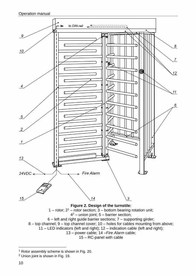
Design of the turnstile is shown in Fig. 2. The numbers of the positions in the Manual are given according to Fig. 2.
The turnstile consists of: rotor (1); barrier sections (5); left and right guide barrier sections (6), LED directional indicators (11); supporting girder (7); top channel (8) with cover (9); RC-panel (15) with cables; units inside the top channel enabling operation of the turnstile.
The rotor (1) is an assembly of three separate sections (2). Each section serves as a barrier wing and consists of vertical support with 10 welded barrier arms. Bottom part of the rotor is inserted into the bottom bearing rotation unit and upper part through the union joint is attached to the shaft of operating mechanism.
The barrier section (5) consists of a supporting girder with barrier arms and a bottom bearing rotation unit (3) fixed on the horizontal base. Barrier section with barrier arms is fixed on the mounting surface through four mounting holes in the flange and one mounting hole in the bottom bearing rotation unit.
The guide barrier set consists of two sections (6): left and right. Each section consists of a supporting girder with flanges. The outer supporting girders are furnished with built-in LED directional indicators (11) with indication cables (12) running through and out of the posts. Each flange has two mounting holes for fixing the guide barrier sections to the mounting surface. Together with the rotor barrier wings the guide barrier sections form the turnstile passageway. The outer supporting girders can be mounted with ACS readers or other supplementary equipment if necessary.
The supporting girder (7) joins the guide barrier sections and provides stability and support for the top channel (8). Indication cables and, if necessary, cables from ACS readers and other equipment are mounted inside the supporting girder.
The top channel (8) joins the barrier section with barrier arms (5), the rotor (1) and the guide barrier sections (6) into a single structure, and serves for placement of basic units ensuring the turnstile operation: the turnstile operating mechanism and the control unit.
It is possible to install walkway downlights on the top channel. If there are no walkway downlights in the delivery set the mounting holes are normally plugged.
Two mechanical release locks are mounted underneath the top channel, symmetrically along its axis. The access to locks is possible from below from the guide barrier section side. Each lock is designed for unlocking the rotor (1) in the direction of the lock’s side.
The top channel is protected by the cover (9) fixed with four screws from below. After fixing the screw holes are closed with plastic plugs.
The operating mechanism is installed on a separate base. The shaft of the operating mechanism is connected to the rotor (1) shaft with the union joint (4) consisting of two half-couplings.
The operating mechanism of the RTD-16.1 model includes also an electric gear motor. In the single passage mode, at the beginning of the passage through the turnstile, the motor switches on as soon as the rotor is revolved about >12º, and makes further automatic rotation in the direction of passage until the rotor is in the home position where it is securely locked. In the free passage mode the electric motor switches into operation only to slow down the rotation of barrier wings near the home position.
Operation manual
10
Figure 2. Design of the turnstile: 1 – rotor; 21 – rotor section; 3 – bottom bearing rotation unit;
42 – union joint; 5 – barrier section; 6 – left and right guide barrier sections; 7 – supporting girder;
8 – top channel; 9 – top channel cover; 10 – holes for cables mounting from above; 11 – LED indicators (left and right); 12 – indication cable (left and right);
13 – power cable; 14 –Fire Alarm cable; 15 – RC-panel with cable
1 Rotor assembly scheme is shown in Fig. 20. 2 Union joint is shown in Fig. 19.
RTD-16 Full Height Rotor Turnstile
11
The operating mechanism of the RTD-16.2 includes a mechanical gear motor. As soon as the rotor has been revolved about >60º the operating mechanism due to the springs energy continues rotation until the rotor is in the home position where it is securely locked. As soon as the rotor has been revolved about >60º the operating mechanism in both modifications blocks the reverse rotation.
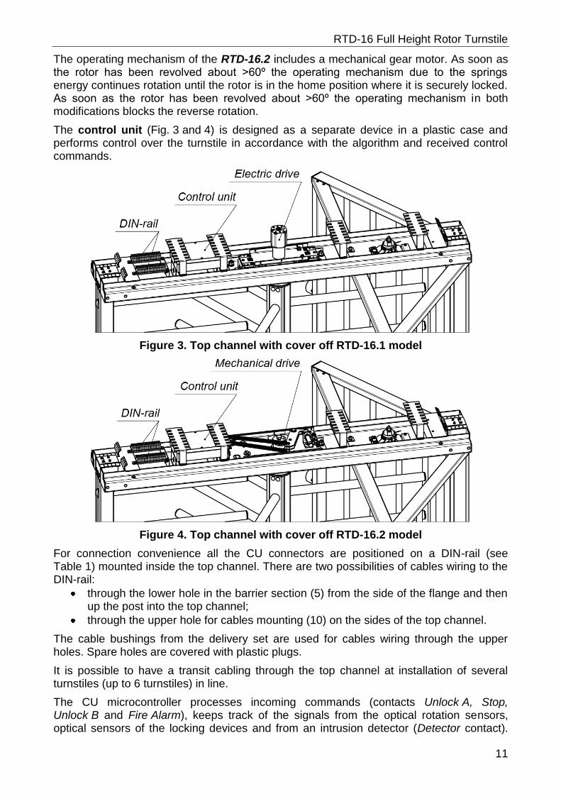
The control unit (Fig. 3 and 4) is designed as a separate device in a plastic case and performs control over the turnstile in accordance with the algorithm and received control commands.
Figure 3. Top channel with cover off RTD-16.1 model
Figure 4. Top channel with cover off RTD-16.2 model
For connection convenience all the CU connectors are positioned on a DIN-rail (see Table 1) mounted inside the top channel. There are two possibilities of cables wiring to the DIN-rail:
through the lower hole in the barrier section (5) from the side of the flange and then up the post into the top channel;
through the upper hole for cables mounting (10) on the sides of the top channel.
The cable bushings from the delivery set are used for cables wiring through the upper holes. Spare holes are covered with plastic plugs.
It is possible to have a transit cabling through the top channel at installation of several turnstiles (up to 6 turnstiles) in line.
The CU microcontroller processes incoming commands (contacts Unlock A, Stop, Unlock B and Fire Alarm), keeps track of the signals from the optical rotation sensors, optical sensors of the locking devices and from an intrusion detector (Detector contact).
Operation manual
12
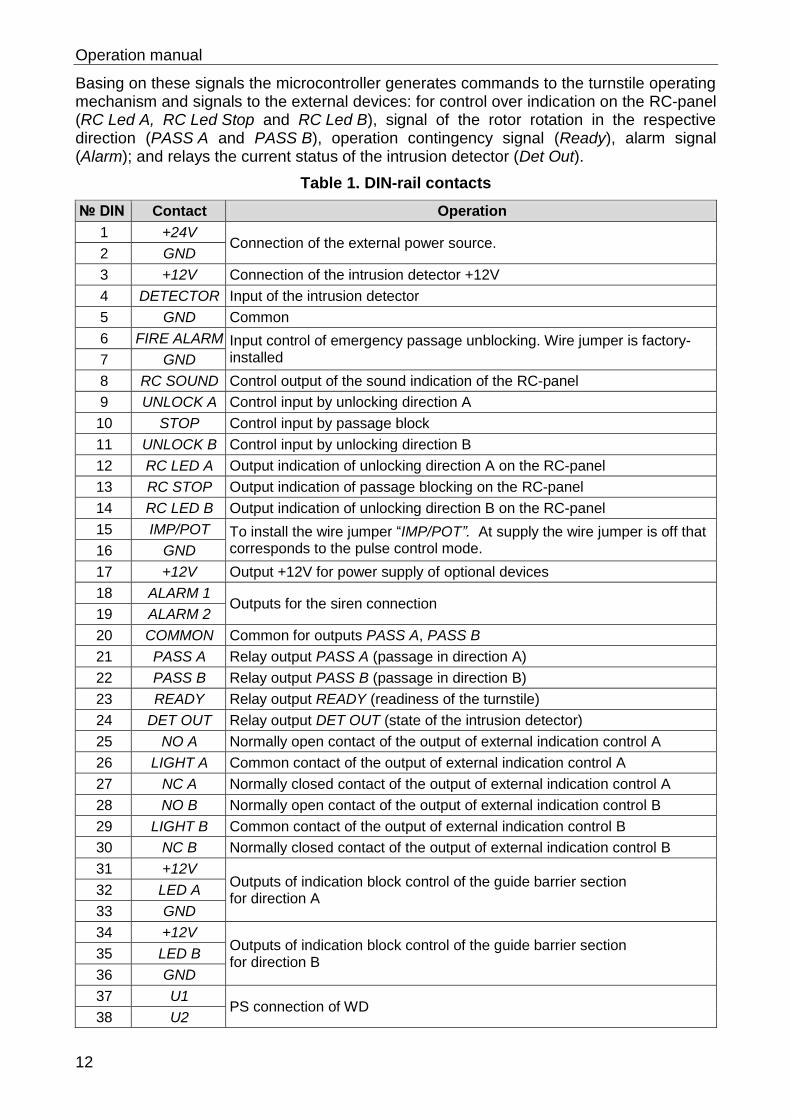
Basing on these signals the microcontroller generates commands to the turnstile operating mechanism and signals to the external devices: for control over indication on the RC-panel (RC Led A, RC Led Stop and RC Led B), signal of the rotor rotation in the respective direction (PASS A and PASS B), operation contingency signal (Ready), alarm signal (Alarm); and relays the current status of the intrusion detector (Det Out).
Table 1. DIN-rail contacts
№ DIN Contact Operation
1 +24V Connection of the external power source.
2 GND
3 +12V Connection of the intrusion detector +12V
4 DETECTOR Input of the intrusion detector
5 GND Common
6 FIRE ALARM Input control of emergency passage unblocking. Wire jumper is factory-installed 7 GND
8 RC SOUND Control output of the sound indication of the RC-panel
9 UNLOCK A Control input by unlocking direction A
10 STOP Control input by passage block
11 UNLOCK B Control input by unlocking direction B
12 RC LED A Output indication of unlocking direction A on the RC-panel
13 RC STOP Output indication of passage blocking on the RC-panel
14 RC LED B Output indication of unlocking direction B on the RC-panel
15 IMP/POT To install the wire jumper “IMP/POT”. At supply the wire jumper is off that corresponds to the pulse control mode. 16 GND
17 +12V Output +12V for power supply of optional devices
18 ALARM 1 Outputs for the siren connection
19 ALARM 2
20 COMMON Common for outputs PASS A, PASS B
21 PASS A Relay output PASS A (passage in direction A)
22 PASS B Relay output PASS B (passage in direction B)
23 READY Relay output READY (readiness of the turnstile)
24 DET OUT Relay output DET OUT (state of the intrusion detector)
25 NO A Normally open contact of the output of external indication control A
26 LIGHT A Common contact of the output of external indication control A
27 NC A Normally closed contact of the output of external indication control A
28 NO B Normally open contact of the output of external indication control B
29 LIGHT B Common contact of the output of external indication control B
30 NC B Normally closed contact of the output of external indication control B
31 +12V Outputs of indication block control of the guide barrier section for direction A
32 LED A
33 GND
34 +12V Outputs of indication block control of the guide barrier section for direction B
35 LED B
36 GND
37 U1 PS connection of WD
38 U2
RTD-16 Full Height Rotor Turnstile
13
5.3 Control of the turnstile
The turnstile can be operated from:
RC-panel (Wireless remote control) when the turnstile works as a single stand barrier device,
ASC controller when the turnstile works as a part of ACS.
Attention!
In case the turnstile is operated from ACS-controller the RC-panel should be connected to the ACS-controller. The ACS-controller and the RC-panel must not be connected to the turnstile simultaneously.
5.3.1 The RC-panel
The RC-panel (15) is designed as a compact desktop device in a shockproof ABS plastic case with a flexible multicore cable.
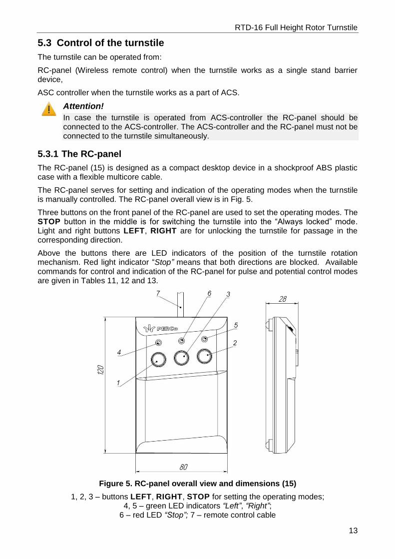
The RC-panel serves for setting and indication of the operating modes when the turnstile is manually controlled. The RC-panel overall view is in Fig. 5.
Three buttons on the front panel of the RC-panel are used to set the operating modes. The STOP button in the middle is for switching the turnstile into the “Always locked” mode. Light and right buttons LEFT, RIGHT are for unlocking the turnstile for passage in the corresponding direction.
Above the buttons there are LED indicators of the position of the turnstile rotation mechanism. Red light indicator “Stop” means that both directions are blocked. Available commands for control and indication of the RC-panel for pulse and potential control modes are given in Tables 11, 12 and 13.
Figure 5. RC-panel overall view and dimensions (15)
1, 2, 3 – buttons LEFT, RIGHT, STOP for setting the operating modes; 4, 5 – green LED indicators “Left”, “Right”;
6 – red LED “Stop”; 7 – remote control cable
Operation manual
14
5.3.2 Control modes
Two control modes – pulse and potential – are available. In both control modes the turnstile is operated by input of the commands (i.e. combination of control signals): Unlock A, Stop and Unlock B and special input Fire Alarm. Instruction issue algorithm depends upon the chosen control mode.
Setting of the control mode
Either control mode is set by the “IMP / POT” jumper on the DIN-rail. If there is no jumper, the turnstile is operated in the pulse control mode, if there is jumper – potential control mode.
Pulse control mode
The pulse control mode is used for control of the turnstile from the RC-panel, a wireless remote control, or via an ACS-controller with outputs supporting pulse control mode.
The minimum input signal duration to change one operating mode for another is 100 ms. The passage waiting time is 5 sec. irrespective of an input signal length.
The turnstile operating modes in the pulse control mode are shown in Tables 11, 12. The algorithm of control signals is given in Appendix 1.
Potential control mode
The potential control mode is used for control of the turnstile via an ACS-controller with outputs supporting potential control mode.
The minimum input signal duration to change one operation mode for another is 100 ms. The passage waiting time equals a low-level signal duration (the turnstile remains open if upon completion of the passage there is still a low-level signal at the input for the permitted direction).
When a low-level signal is received to the Stop input, both directions close for as long as the signal is present, regardless of signal levels at the Unlock A and Unlock B inputs. When the low signal is removed from the Stop input, status of each direction is determined by respective signal levels at the Unlock A and Unlock B inputs.
Note:
To set a single passage mode in the potential control mode it is recommended to remove a low-level signal from the Unlock A / Unlock B inputs and activate relay output PASS A / PASS B of the respective direction.
The turnstile operating modes in the potential control mode are shown in Table 13. The algorithm of control signals is given in Appendix 2.
5.3.3 Logic operational sequence in the pulse operation mode
Logic operational sequence in the pulse operation mode in “Single passage” in the set direction:
1. The control device (the RC-panel, the WRC, ACS-controller) sends the incoming command (combination of control signals) to the CU inputs to unlock the passage in the chosen direction.
2. The CU microcontroller processes the incoming combination of signals and generates a command to the turnstile operating mechanism to unlock the rotation mechanism. From this moment the countdown of fixing the turnstile stopper knot in the unlocked position starts.
3. The operating mechanism unlocks the rotation mechanism for rotation in the set direction. The passage in the set direction becomes possible.
RTD-16 Full Height Rotor Turnstile
15
4. If the revolving of the rotor does not commence the command to block the rotation mechanism is generated upon the lapse of hold time of the turnstile in the unlocked position (per default – 5 seconds from the moment of the receipt of the command).
5. During the passage the rotation angle of the rotor is monitored by the microcontroller with the help of optic sensors of the control mechanism. When the rotation angle is more than 67° the passage is registered. One of the relay outputs corresponding to the passage direction (PASS A or PASS B) is activated.
6. For RTD-16.1 after the rotor turns 12°30´ the control unit of the RTD-16.1 generates a command for automatic rotation in the set direction.
7. When the passage is done and the rotor is in the home position (turn on 120°), the rotation mechanism of the turnstile is blocked. Relay output PASS A / PASS B is normalized.
8. The turnstile is ready for the next passage.
5.3.4 Parameters of control signals
Note:
As means of a high-level signal generation at all the input contacts (Unlock A, Stop, Unlock B, Fire Alarm and Detector) the control unit uses 1-KOhm resistors wired to the power supply bus + 5 V.
Standard control inputs: connectors 9…11 DIN-rail (Unlock A, Stop and Unlock B).
Special control input: connector 6 DIN-rail (Fire Alarm).
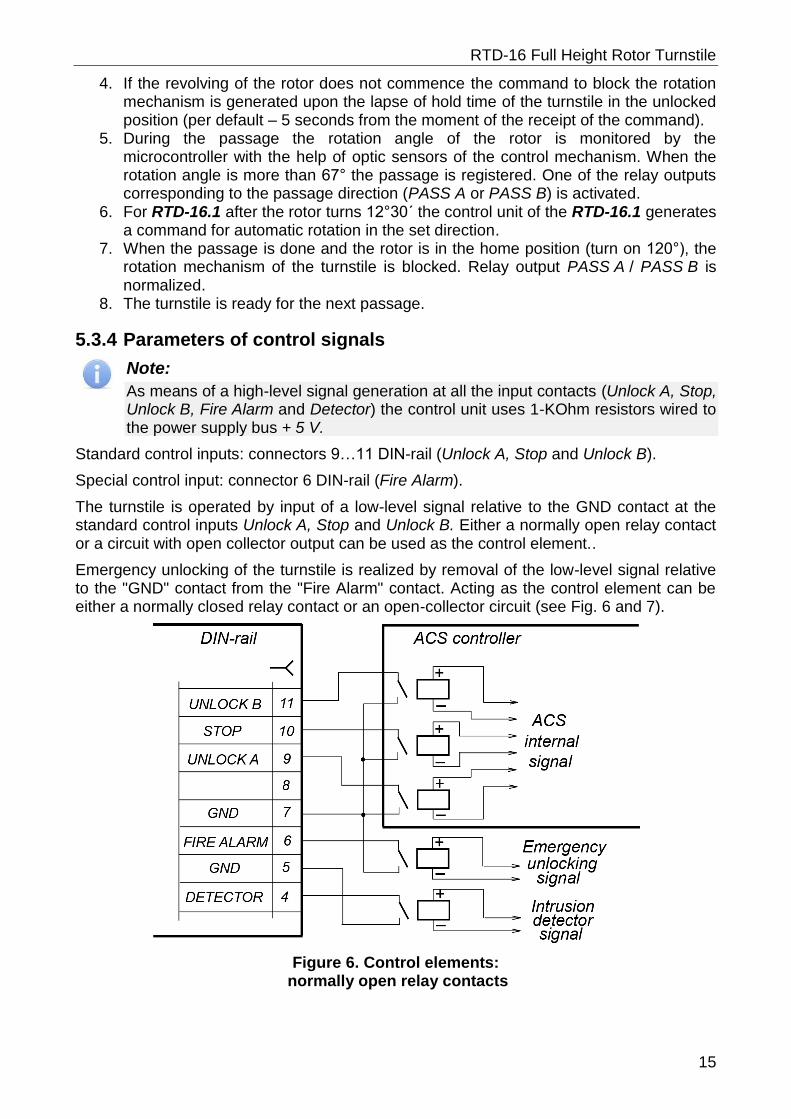
The turnstile is operated by input of a low-level signal relative to the GND contact at the standard control inputs Unlock A, Stop and Unlock B. Either a normally open relay contact or a circuit with open collector output can be used as the control element..
Emergency unlocking of the turnstile is realized by removal of the low-level signal relative to the "GND" contact from the "Fire Alarm" contact. Acting as the control element can be either a normally closed relay contact or an open-collector circuit (see Fig. 6 and 7).
Figure 6. Control elements: normally open relay contacts
Operation manual
16
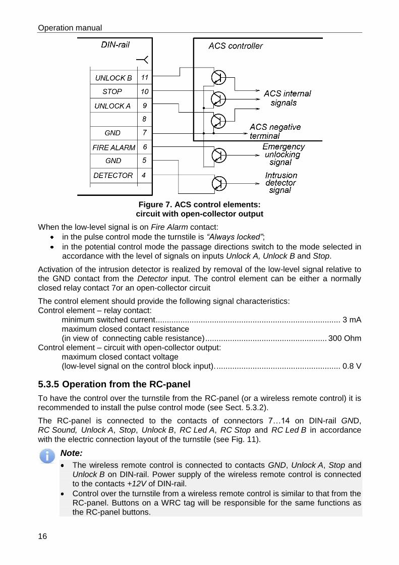
Figure 7. ACS control elements: circuit with open-collector output
When the low-level signal is on Fire Alarm contact:
in the pulse control mode the turnstile is “Always locked”;
in the potential control mode the passage directions switch to the mode selected in accordance with the level of signals on inputs Unlock A, Unlock B and Stop.
Activation of the intrusion detector is realized by removal of the low-level signal relative to the GND contact from the Detector input. The control element can be either a normally closed relay contact 7or an open-collector circuit
The control element should provide the following signal characteristics: Control element – relay contact:
minimum switched current .................................................................................. 3 mA maximum closed contact resistance (in view of connecting cable resistance) ...................................................... 300 Ohm
Control element – circuit with open-collector output: maximum closed contact voltage (low-level signal on the control block input). ....................................................... 0.8 V
5.3.5 Operation from the RC-panel
To have the control over the turnstile from the RC-panel (or a wireless remote control) it is recommended to install the pulse control mode (see Sect. 5.3.2).
The RC-panel is connected to the contacts of connectors 7…14 on DIN-rail GND, RC Sound, Unlock A, Stop, Unlock B, RC Led A, RC Stop and RC Led B in accordance with the electric connection layout of the turnstile (see Fig. 11).
Note:
The wireless remote control is connected to contacts GND, Unlock A, Stop and Unlock B on DIN-rail. Power supply of the wireless remote control is connected to the contacts +12V of DIN-rail.
Control over the turnstile from a wireless remote control is similar to that from the RC-panel. Buttons on a WRC tag will be responsible for the same functions as the RC-panel buttons.
RTD-16 Full Height Rotor Turnstile
17
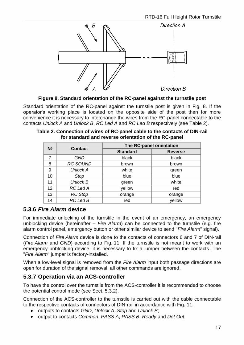
Figure 8. Standard orientation of the RC-panel against the turnstile post
Standard orientation of the RC-panel against the turnstile post is given in Fig. 8. If the operator’s working place is located on the opposite side of the post then for more convenience it is necessary to interchange the wires from the RC-panel connectable to the contacts Unlock A and Unlock B, RC Led A and RC Led B respectively (see Table 2).
Table 2. Connection of wires of RC-panel cable to the contacts of DIN-rail for standard and reverse orientation of the RC-panel
№ Contact The RC-panel orientation
Standard Reverse
7 GND black black
8 RC SOUND brown brown
9 Unlock A white green
10 Stop blue blue
11 Unlock B green white
12 RC Led A yellow red
13 RC Stop orange orange
14 RC Led B red yellow
5.3.6 Fire Alarm device
For immediate unlocking of the turnstile in the event of an emergency, an emergency unblocking device (hereinafter – Fire Alarm) can be connected to the turnstile (e.g. fire alarm control panel, emergency button or other similar device to send "Fire Alarm" signal).
Connection of Fire Alarm device is done to the contacts of connectors 6 and 7 of DIN-rail (Fire Alarm and GND) according to Fig. 11. If the turnstile is not meant to work with an emergency unblocking device, it is necessary to fix a jumper between the contacts. The "Fire Alarm" jumper is factory-installed.
When a low-level signal is removed from the Fire Alarm input both passage directions are open for duration of the signal removal, all other commands are ignored.
5.3.7 Operation via an ACS-controller
To have the control over the turnstile from the ACS-controller it is recommended to choose the potential control mode (see Sect. 5.3.2).
Connection of the ACS-controller to the turnstile is carried out with the cable connectable to the respective contacts of connectors of DIN-rail in accordance with Fig. 11:
outputs to contacts GND, Unlock A, Stop and Unlock B;
output to contacts Common, PASS A, PASS B, Ready and Det Out.
Operation manual
18
5.4 Optional devices that can be connected to the turnstile
Attention!
When connecting any additional devices, account must be taken that the control unit provides the necessary 12±2 V feeding if the total load of all connected devices does not exceed 300 mA.
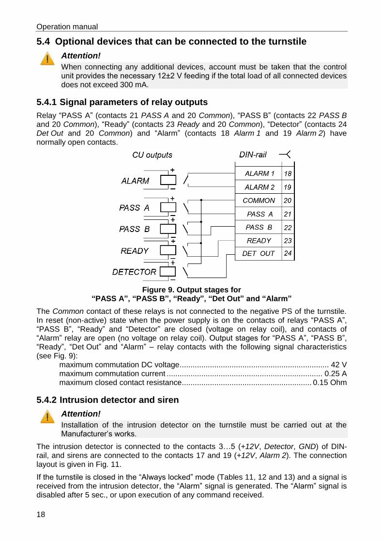
5.4.1 Signal parameters of relay outputs
Relay “PASS A” (contacts 21 PASS A and 20 Common), “PASS B” (contacts 22 PASS B and 20 Common), “Ready” (contacts 23 Ready and 20 Common), “Detector” (contacts 24 Det Out and 20 Common) and “Alarm” (contacts 18 Alarm 1 and 19 Alarm 2) have normally open contacts.
Figure 9. Output stages for “PASS A”, “PASS B”, “Ready”, “Det Out” and “Alarm”
The Common contact of these relays is not connected to the negative PS of the turnstile. In reset (non-active) state when the power supply is on the contacts of relays “PASS A”, “PASS B”, “Ready” and “Detector” are closed (voltage on relay coil), and contacts of “Alarm” relay are open (no voltage on relay coil). Output stages for “PASS A”, “PASS B”, “Ready”, “Det Out” and “Alarm” – relay contacts with the following signal characteristics (see Fig. 9):
maximum commutation DC voltage ..................................................................... 42 V maximum commutation current ........................................................................ 0.25 A maximum closed contact resistance ............................................................ 0.15 Ohm
5.4.2 Intrusion detector and siren
Attention!
Installation of the intrusion detector on the turnstile must be carried out at the Manufacturer’s works.
The intrusion detector is connected to the contacts 3…5 (+12V, Detector, GND) of DIN-rail, and sirens are connected to the contacts 17 and 19 (+12V, Alarm 2). The connection layout is given in Fig. 11.
If the turnstile is closed in the “Always locked” mode (Tables 11, 12 and 13) and a signal is received from the intrusion detector, the “Alarm” signal is generated. The “Alarm” signal is disabled after 5 sec., or upon execution of any command received.
RTD-16 Full Height Rotor Turnstile
19
The intrusion detector signal is ignored when the turnstile is open for passage in one or both directions, and over 3 sec. after the turnstile is set in the “Always locked” mode.
The intrusion detector current status signal (see Fig. 7) is constantly relayed to the contact 24 Det Out of DIN-rail relative to the contact 20 Common (see Fig. 11).
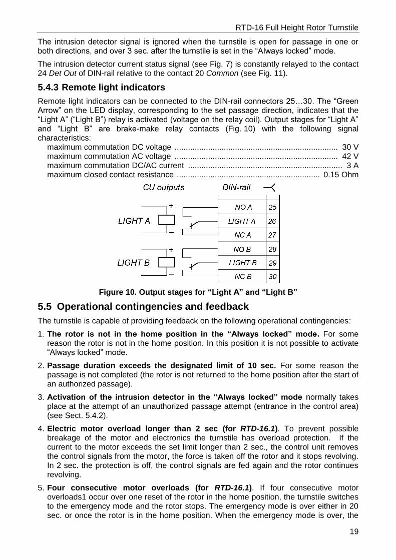
5.4.3 Remote light indicators
Remote light indicators can be connected to the DIN-rail connectors 25…30. The “Green Arrow” on the LED display, corresponding to the set passage direction, indicates that the “Light A” (“Light B”) relay is activated (voltage on the relay coil). Output stages for “Light A” and “Light B” are brake-make relay contacts (Fig. 10) with the following signal characteristics:
maximum commutation DC voltage ......................................................................... 30 V maximum commutation AC voltage ......................................................................... 42 V maximum commutation DC/AC current ..................................................................... 3 A maximum closed contact resistance ................................................................ 0.15 Ohm
Figure 10. Output stages for “Light A” and “Light B”
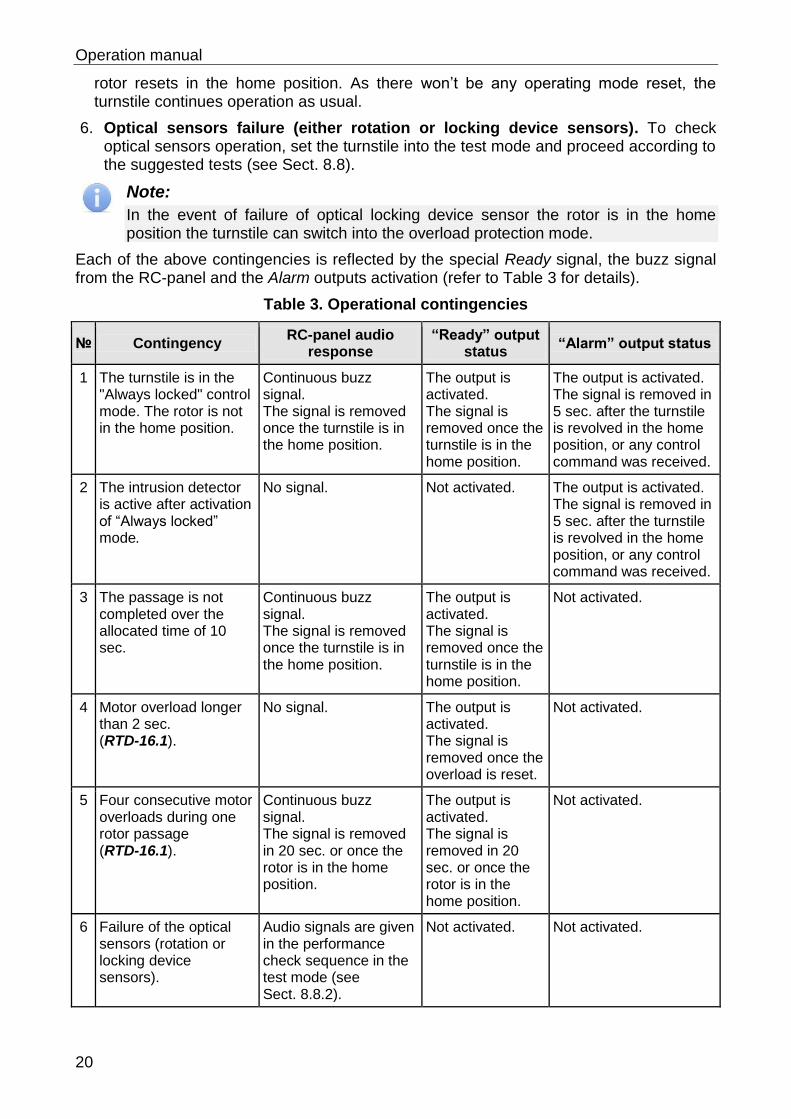
5.5 Operational contingencies and feedback
The turnstile is capable of providing feedback on the following operational contingencies:
1. The rotor is not in the home position in the “Always locked” mode. For some reason the rotor is not in the home position. In this position it is not possible to activate “Always locked” mode.
2. Passage duration exceeds the designated limit of 10 sec. For some reason the passage is not completed (the rotor is not returned to the home position after the start of an authorized passage).
3. Activation of the intrusion detector in the “Always locked” mode normally takes place at the attempt of an unauthorized passage attempt (entrance in the control area) (see Sect. 5.4.2).
4. Electric motor overload longer than 2 sec (for RTD-16.1). To prevent possible breakage of the motor and electronics the turnstile has overload protection. If the current to the motor exceeds the set limit longer than 2 sec., the control unit removes the control signals from the motor, the force is taken off the rotor and it stops revolving. In 2 sec. the protection is off, the control signals are fed again and the rotor continues revolving.
5. Four consecutive motor overloads (for RTD-16.1). If four consecutive motor overloads1 occur over one reset of the rotor in the home position, the turnstile switches to the emergency mode and the rotor stops. The emergency mode is over either in 20 sec. or once the rotor is in the home position. When the emergency mode is over, the
Operation manual
20
rotor resets in the home position. As there won’t be any operating mode reset, the turnstile continues operation as usual.
6. Optical sensors failure (either rotation or locking device sensors). To check optical sensors operation, set the turnstile into the test mode and proceed according to the suggested tests (see Sect. 8.8).
Note:
In the event of failure of optical locking device sensor the rotor is in the home position the turnstile can switch into the overload protection mode.
Each of the above contingencies is reflected by the special Ready signal, the buzz signal from the RC-panel and the Alarm outputs activation (refer to Table 3 for details).
Table 3. Operational contingencies
№ Contingency RC-panel audio
response “Ready” output
status “Alarm” output status
1 The turnstile is in the "Always locked" control mode. The rotor is not in the home position.
Continuous buzz signal. The signal is removed once the turnstile is in the home position.
The output is activated. The signal is removed once the turnstile is in the home position.
The output is activated. The signal is removed in 5 sec. after the turnstile is revolved in the home position, or any control command was received.
2 The intrusion detector is active after activation of “Always locked” mode.
No signal. Not activated. The output is activated. The signal is removed in 5 sec. after the turnstile is revolved in the home position, or any control command was received.
3 The passage is not completed over the allocated time of 10 sec.
Continuous buzz signal. The signal is removed once the turnstile is in the home position.
The output is activated. The signal is removed once the turnstile is in the home position.
Not activated.
4 Motor overload longer than 2 sec. (RTD-16.1).
No signal. The output is activated. The signal is removed once the overload is reset.
Not activated.
5 Four consecutive motor overloads during one rotor passage (RTD-16.1).
Continuous buzz signal. The signal is removed in 20 sec. or once the rotor is in the home position.
The output is activated. The signal is removed in 20 sec. or once the rotor is in the home position.
Not activated.
6 Failure of the optical sensors (rotation or locking device sensors).
Audio signals are given in the performance check sequence in the test mode (see Sect. 8.8.2).
Not activated. Not activated.
RTD-16 Full Height Rotor Turnstile
21
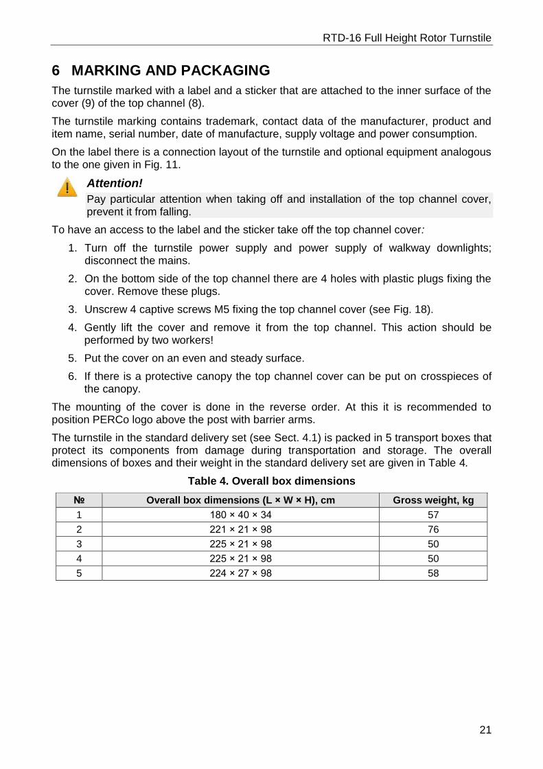
6 MARKING AND PACKAGING
The turnstile marked with a label and a sticker that are attached to the inner surface of the cover (9) of the top channel (8).
The turnstile marking contains trademark, contact data of the manufacturer, product and item name, serial number, date of manufacture, supply voltage and power consumption.
On the label there is a connection layout of the turnstile and optional equipment analogous to the one given in Fig. 11.
Attention!
Pay particular attention when taking off and installation of the top channel cover, prevent it from falling.
To have an access to the label and the sticker take off the top channel cover:
1. Turn off the turnstile power supply and power supply of walkway downlights; disconnect the mains.
2. On the bottom side of the top channel there are 4 holes with plastic plugs fixing the cover. Remove these plugs.
3. Unscrew 4 captive screws M5 fixing the top channel cover (see Fig. 18).
4. Gently lift the cover and remove it from the top channel. This action should be performed by two workers!
5. Put the cover on an even and steady surface.
6. If there is a protective canopy the top channel cover can be put on crosspieces of the canopy.
The mounting of the cover is done in the reverse order. At this it is recommended to position PERCo logo above the post with barrier arms.
The turnstile in the standard delivery set (see Sect. 4.1) is packed in 5 transport boxes that protect its components from damage during transportation and storage. The overall dimensions of boxes and their weight in the standard delivery set are given in Table 4.
Table 4. Overall box dimensions
№ Overall box dimensions (L × W × H), cm Gross weight, kg
1 180 × 40 × 34 57
2 221 × 21 × 98 76
3 225 × 21 × 98 50
4 225 × 21 × 98 50
5 224 × 27 × 98 58
Operation manual
22
7 SAFETY REQUIREMENTS
7.1 Installation safety requirements
Installation of the turnstile should be carried out by qualified personnel only, in strict accordance with this Manual and general safety requirements for electrical and installation work.
Caution!
Turn off and unplug all power supplies before work.
Use only serviceable tools.
Unpacking, installation, moving of the turnstile sections, installation of the top channel, its cover and the rotor should be carried out by at least two persons.
Use protective gloves to avoid injury.
Be careful when taking off and on bulky and heavy parts such as the top channel cover, half-couplings, rotor and make extra sure to prevent them from fall.
Make sure the installation is correct before the first use of the turnstile.
Power supply units and other optional equipment should be used according to safety requirements given in their respective operation manuals.
7.2 Operational safety requirements
Observe general safety requirements for use of electrical equipment.
Caution:
The turnstile must not be used in conditions different from those given in Sect. 2.
The turnstile must not be used with supply voltage different from that given in Sect. 3.
To avoid injuries – do not step or hang on the turnstile barrier arms, do not pass hands or legs between the barrier arms during the turnstile operation etc.
Power supply units and other optional equipment should be used according to safety requirements in respective operation manuals.
RTD-16 Full Height Rotor Turnstile
23
8 INSTALLATION
During the turnstile installation follow the safety measures specified in sect. 7.1.
The installation should be carried out by at least two persons qualified in assembly and electric work.
Proper installation is critical to performance and serviceability of the turnstile. We strongly advise to study this section before installation work, and follow the instructions to the letter. It is recommended to proceed with installation only after thorough reading of this section and study of the assembly & installation film.
Attention!
The manufacturer will not accept liability for any damage to the turnstile or other equipment, or otherwise loss caused as a result of improper installation, and will dismiss any claims by the customer should the installation work be carried out not in accordance with this Operation Manual.
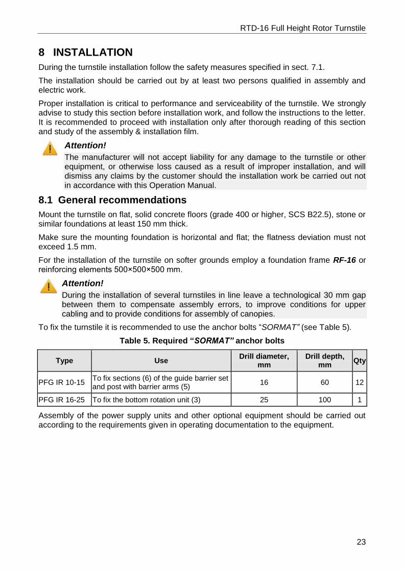
8.1 General recommendations
Mount the turnstile on flat, solid concrete floors (grade 400 or higher, SCS B22.5), stone or similar foundations at least 150 mm thick.
Make sure the mounting foundation is horizontal and flat; the flatness deviation must not exceed 1.5 mm.
For the installation of the turnstile on softer grounds employ a foundation frame RF-16 or reinforcing elements 500×500×500 mm.
Attention!
During the installation of several turnstiles in line leave a technological 30 mm gap between them to compensate assembly errors, to improve conditions for upper cabling and to provide conditions for assembly of canopies.
To fix the turnstile it is recommended to use the anchor bolts “SORMAT” (see Table 5).
Table 5. Required “SORMAT” anchor bolts
Type Use Drill diameter,
mm Drill depth,
mm Qty
PFG IR 10-15 To fix sections (6) of the guide barrier set and post with barrier arms (5)
16 60 12
PFG IR 16-25 To fix the bottom rotation unit (3) 25 100 1
Assembly of the power supply units and other optional equipment should be carried out according to the requirements given in operating documentation to the equipment.
Operation manual
24
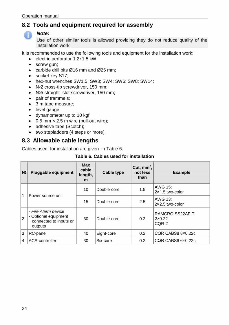
8.2 Tools and equipment required for assembly
Note:
Use of other similar tools is allowed providing they do not reduce quality of the installation work.
It is recommended to use the following tools and equipment for the installation work:
electric perforator 1.2 1.5 kW;
screw gun;
carbide drill bits Ø16 mm and Ø25 mm;
socket key S17;
hex-nut wrenches SW1.5; SW3; SW4; SW6; SW8; SW14;
№2 cross-tip screwdriver, 150 mm;
№5 straight- slot screwdriver, 150 mm;
pair of trammels;
3 m tape measure;
level gauge;
dynamometer up to 10 kgf;
0.5 mm × 2.5 m wire (pull-out wire);
adhesive tape (Scotch);
two stepladders (4 steps or more).
8.3 Allowable cable lengths
Cables used for installation are given in Table 6.
Table 6. Cables used for installation
№ Pluggable equipment
Max cable
length, m
Cable type Cut, mm2, not less
than Example
1 Power source unit
10 Double-core 1.5 AWG 15; 2×1.5 two-color
15 Double-core 2.5 AWG 13; 2×2.5 two-color
2
- Fire Alarm device - Optional equipment
connected to inputs or outputs
30 Double-core 0.2 RAMCRO SS22AF-T 2×0.22 CQR-2
3 RC-panel 40 Eight-core 0.2 CQR CABS8 8×0.22c
4 ACS-controller 30 Six-core 0.2 CQR CABS6 6×0.22c
RTD-16 Full Height Rotor Turnstile
25
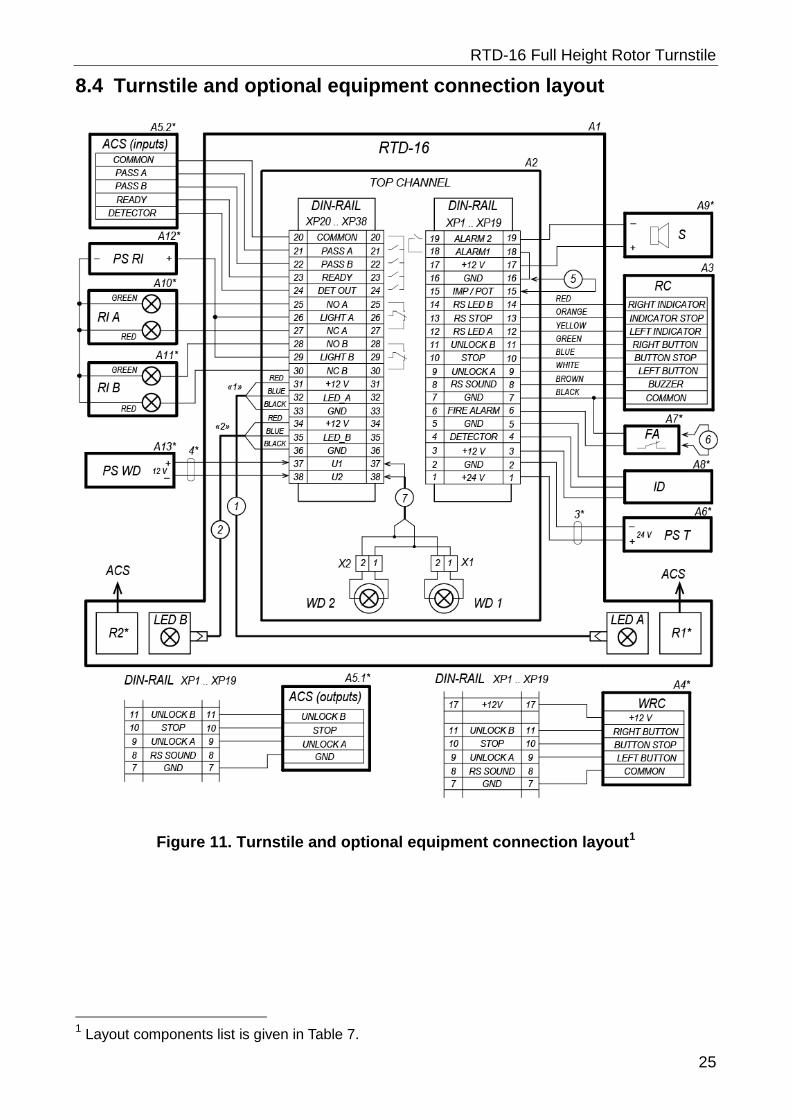
8.4 Turnstile and optional equipment connection layout
Figure 11. Turnstile and optional equipment connection layout1
1 Layout components list is given in Table 7.
Operation manual
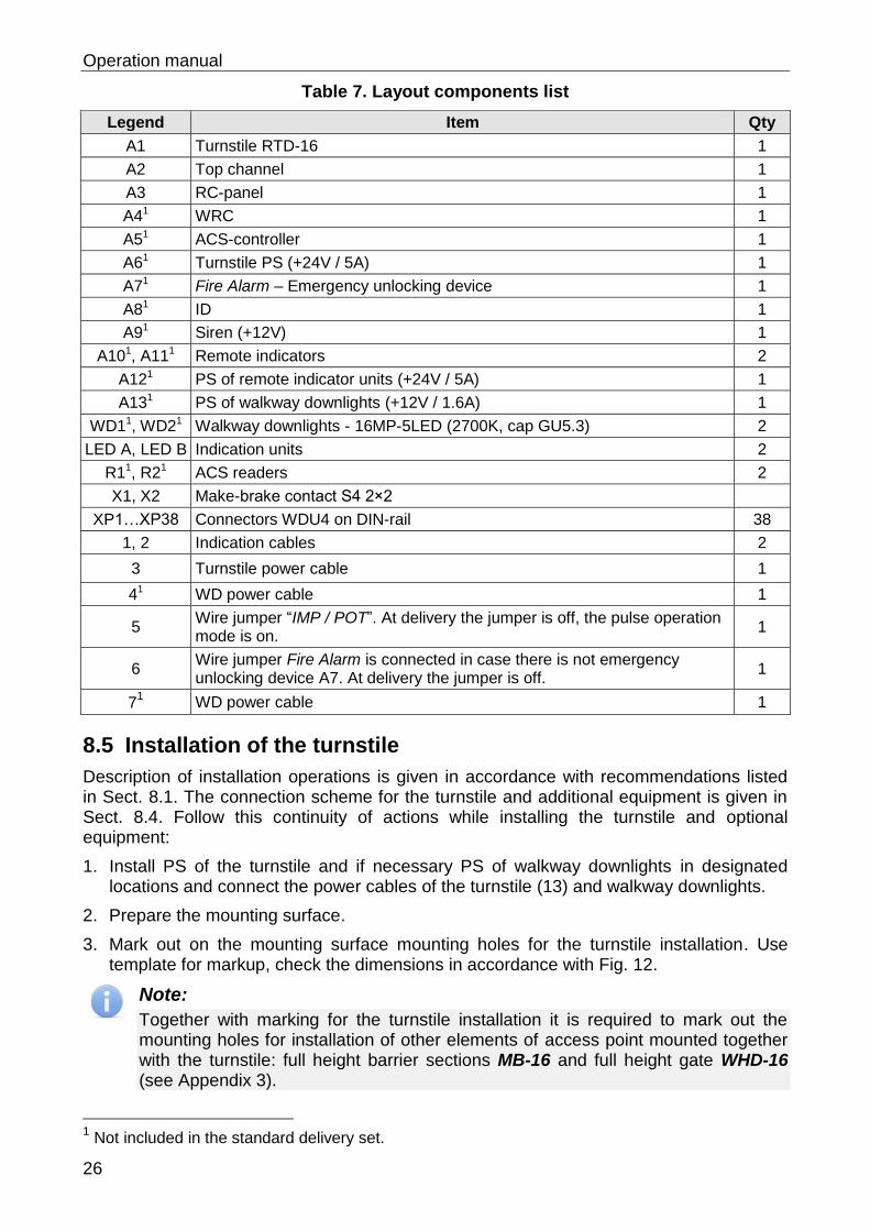
26
Table 7. Layout components list
Legend Item Qty
A1 Turnstile RTD-16 1
A2 Top channel 1
A3 RC-panel 1
A41 WRC 1
A51 ACS-controller 1
A61 Turnstile PS (+24V / 5A) 1
A71 Fire Alarm – Emergency unlocking device 1
A81 ID 1
A91 Siren (+12V) 1
A101, A111 Remote indicators 2
A121 PS of remote indicator units (+24V / 5A) 1
A131 PS of walkway downlights (+12V / 1.6A) 1
WD11, WD21 Walkway downlights - 16MP-5LED (2700K, cap GU5.3) 2
LED A, LED B Indication units 2
R11, R21 ACS readers 2
X1, X2 Make-brake contact S4 2×2
XP1…XP38 Connectors WDU4 on DIN-rail 38
1, 2 Indication cables 2
3 Turnstile power cable 1
41 WD power cable 1
5 Wire jumper “IMP / POT”. At delivery the jumper is off, the pulse operation mode is on.
1
6 Wire jumper Fire Alarm is connected in case there is not emergency unlocking device A7. At delivery the jumper is off.
1
71 WD power cable 1
8.5 Installation of the turnstile
Description of installation operations is given in accordance with recommendations listed in Sect. 8.1. The connection scheme for the turnstile and additional equipment is given in Sect. 8.4. Follow this continuity of actions while installing the turnstile and optional equipment:
1. Install PS of the turnstile and if necessary PS of walkway downlights in designated locations and connect the power cables of the turnstile (13) and walkway downlights.
2. Prepare the mounting surface.
3. Mark out on the mounting surface mounting holes for the turnstile installation. Use template for markup, check the dimensions in accordance with Fig. 12.
Note:
Together with marking for the turnstile installation it is required to mark out the mounting holes for installation of other elements of access point mounted together with the turnstile: full height barrier sections MB-16 and full height gate WHD-16 (see Appendix 3).
1 Not included in the standard delivery set.
RTD-16 Full Height Rotor Turnstile
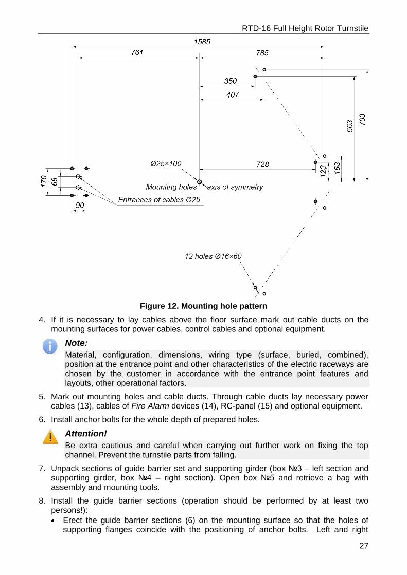
27
Figure 12. Mounting hole pattern
4. If it is necessary to lay cables above the floor surface mark out cable ducts on the mounting surfaces for power cables, control cables and optional equipment.
Note:
Material, configuration, dimensions, wiring type (surface, buried, combined), position at the entrance point and other characteristics of the electric raceways are chosen by the customer in accordance with the entrance point features and layouts, other operational factors.
5. Mark out mounting holes and cable ducts. Through cable ducts lay necessary power cables (13), cables of Fire Alarm devices (14), RC-panel (15) and optional equipment.
6. Install anchor bolts for the whole depth of prepared holes.
Attention!
Be extra cautious and careful when carrying out further work on fixing the top channel. Prevent the turnstile parts from falling.
7. Unpack sections of guide barrier set and supporting girder (box №3 – left section and supporting girder, box №4 – right section). Open box №5 and retrieve a bag with assembly and mounting tools.
8. Install the guide barrier sections (operation should be performed by at least two persons!):
Erect the guide barrier sections (6) on the mounting surface so that the holes of supporting flanges coincide with the positioning of anchor bolts. Left and right
Operation manual
28
sections should have right positioning and orientation: indication blocks of the guide barrier sections should be turned out of the axis of symmetry (see Fig. 12); consider the positioning of the support post fixing points on the sections (see Fig. 13).
Fix the guide barrier sections on the mounting surface with anchor bolts M10×50. Anchor the sections but not tightly, so that you can make the adjustment.
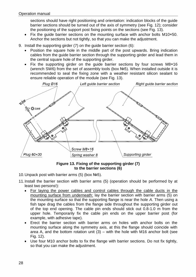
9. Install the supporting girder (7) on the guide barrier section (6):
Position the square hole in the middle part of the post upwards. Bring indication cables from the guide barrier section through the supporting girder and lead them in the central square hole of the supporting girder.
Fix the supporting girder on the guide barrier sections by four screws M8×16 (wrench SW6) from the set of assembly tools (box №5). When installed outside it is recommended to seal the fixing zone with a weather resistant silicon sealant to ensure reliable operation of the module (see Fig. 13).
Figure 13. Fixing of the supporting girder (7) to the barrier sections (6)
10. Unpack post with barrier arms (5) (box №5).
11. Install the barrier section with barrier arms (5) (operation should be performed by at least two persons!):
For laying the power cables and control cables through the cable ducts in the mounting surface from underneath: lay the barrier section with barrier arms (5) on the mounting surface so that the supporting flange is near the hole A. Then using a fish tape drag the cables from the flange side throughout the supporting girder out of the top end opening. The cable pin ends should stick out 0.8-1.0 m from the upper hole. Temporarily fix the cable pin ends on the upper barrier post (for example, with adhesive tape).
Erect the barrier section with barrier arms on holes with anchor bolts on the mounting surface along the symmetry axis, at this the flange should coincide with area A, and the bottom rotation unit (3) – with the hole with M16 anchor bolt (see Fig. 12).
Use four M10 anchor bolts to fix the flange with barrier sections. Do not fix tightly, so that you can make the adjustment.
RTD-16 Full Height Rotor Turnstile
29
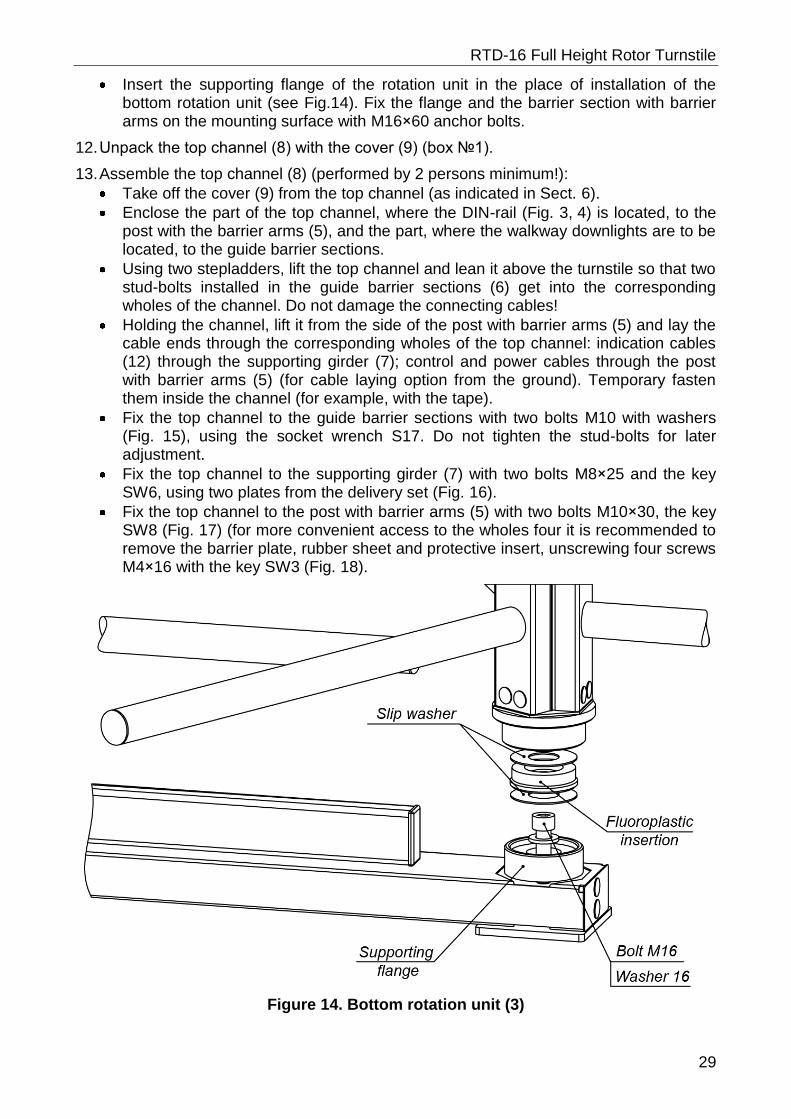
Insert the supporting flange of the rotation unit in the place of installation of the bottom rotation unit (see Fig.14). Fix the flange and the barrier section with barrier arms on the mounting surface with M16×60 anchor bolts.
12. Unpack the top channel (8) with the cover (9) (box №1).
13. Assemble the top channel (8) (performed by 2 persons minimum!):
Take off the cover (9) from the top channel (as indicated in Sect. 6).
Enclose the part of the top channel, where the DIN-rail (Fig. 3, 4) is located, to the post with the barrier arms (5), and the part, where the walkway downlights are to be located, to the guide barrier sections.
Using two stepladders, lift the top channel and lean it above the turnstile so that two stud-bolts installed in the guide barrier sections (6) get into the corresponding wholes of the channel. Do not damage the connecting cables!
Holding the channel, lift it from the side of the post with barrier arms (5) and lay the cable ends through the corresponding wholes of the top channel: indication cables (12) through the supporting girder (7); control and power cables through the post with barrier arms (5) (for cable laying option from the ground). Temporary fasten them inside the channel (for example, with the tape).
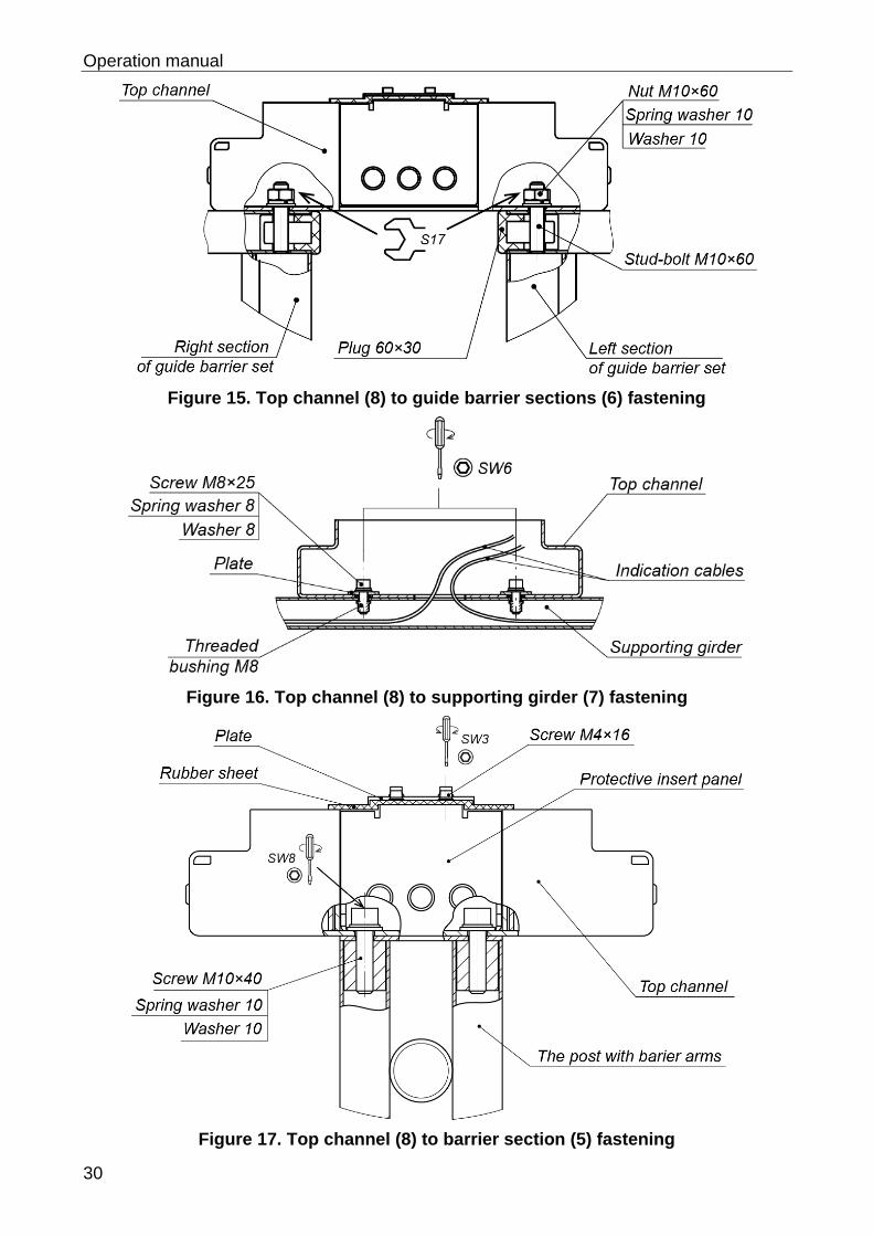
Fix the top channel to the guide barrier sections with two bolts M10 with washers (Fig. 15), using the socket wrench S17. Do not tighten the stud-bolts for later adjustment.
Fix the top channel to the supporting girder (7) with two bolts M8×25 and the key SW6, using two plates from the delivery set (Fig. 16).
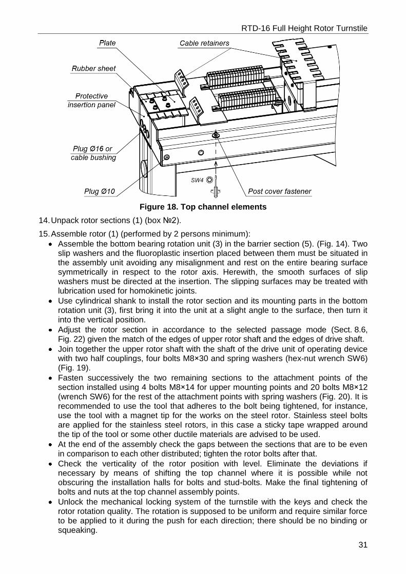
Fix the top channel to the post with barrier arms (5) with two bolts M10×30, the key SW8 (Fig. 17) (for more convenient access to the wholes four it is recommended to remove the barrier plate, rubber sheet and protective insert, unscrewing four screws M4×16 with the key SW3 (Fig. 18).
Figure 14. Bottom rotation unit (3)
Operation manual
30
Figure 15. Top channel (8) to guide barrier sections (6) fastening
Figure 16. Top channel (8) to supporting girder (7) fastening
Figure 17. Top channel (8) to barrier section (5) fastening
RTD-16 Full Height Rotor Turnstile
31
Figure 18. Top channel elements
14. Unpack rotor sections (1) (box №2).
15. Assemble rotor (1) (performed by 2 persons minimum):
Assemble the bottom bearing rotation unit (3) in the barrier section (5). (Fig. 14). Two slip washers and the fluoroplastic insertion placed between them must be situated in the assembly unit avoiding any misalignment and rest on the entire bearing surface symmetrically in respect to the rotor axis. Herewith, the smooth surfaces of slip washers must be directed at the insertion. The slipping surfaces may be treated with lubrication used for homokinetic joints.
Use cylindrical shank to install the rotor section and its mounting parts in the bottom rotation unit (3), first bring it into the unit at a slight angle to the surface, then turn it into the vertical position.
Adjust the rotor section in accordance to the selected passage mode (Sect. 8.6, Fig. 22) given the match of the edges of upper rotor shaft and the edges of drive shaft.
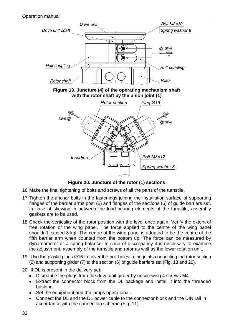
Join together the upper rotor shaft with the shaft of the drive unit of operating device with two half couplings, four bolts M8×30 and spring washers (hex-nut wrench SW6) (Fig. 19).
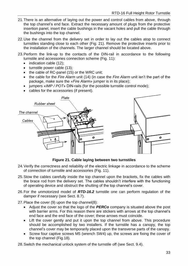
Fasten successively the two remaining sections to the attachment points of the section installed using 4 bolts M8×14 for upper mounting points and 20 bolts M8×12 (wrench SW6) for the rest of the attachment points with spring washers (Fig. 20). It is recommended to use the tool that adheres to the bolt being tightened, for instance, use the tool with a magnet tip for the works on the steel rotor. Stainless steel bolts are applied for the stainless steel rotors, in this case a sticky tape wrapped around the tip of the tool or some other ductile materials are advised to be used.
At the end of the assembly check the gaps between the sections that are to be even in comparison to each other distributed; tighten the rotor bolts after that.
Check the verticality of the rotor position with level. Eliminate the deviations if necessary by means of shifting the top channel where it is possible while not obscuring the installation halls for bolts and stud-bolts. Make the final tightening of bolts and nuts at the top channel assembly points.
Unlock the mechanical locking system of the turnstile with the keys and check the rotor rotation quality. The rotation is supposed to be uniform and require similar force to be applied to it during the push for each direction; there should be no binding or squeaking.
Operation manual
32
Figure 19. Juncture (4) of the operating mechanism shaft with the rotor shaft by the union joint (1)
Figure 20. Juncture of the rotor (1) sections
16. Make the final tightening of bolts and screws of all the parts of the turnstile.
17. Tighten the anchor bolts in the fastenings joining the installation surface of supporting flanges of the barrier arms post (5) and flanges of the sections (6) of guide barriers set. In case of skewing in between the load-bearing elements of the turnstile, assembly gaskets are to be used.
18. Check the verticality of the rotor position with the level once again. Verify the extent of free rotation of the wing panel. The force applied to the centre of the wing panel shouldn’t exceed 3 kgf. The centre of the wing panel is adopted to be the centre of the fifth barrier arm when counted from the bottom up. The force can be measured by dynamometer or a spring balance. In case of discrepancy it is necessary to examine the adjustment, assembly of the turnstile and rotor as well as the lower rotation unit.
19. Use the plastic plugs Ø16 to cover the bolt holes in the joints connecting the rotor section (2) and supporting girder (7) to the section (6) of guide barriers set (Fig. 13 and 20).
20. If DL is present in the delivery set:
Dismantle the plugs from the drive unit girder by unscrewing 4 screws M4.
Extract the connector block from the DL package and install it into the threaded bushing.
Set the equipment and the lamps operational.
Connect the DL and the DL power cable to the connector block and the DIN rail in accordance with the connection scheme (Fig. 11).
RTD-16 Full Height Rotor Turnstile
33
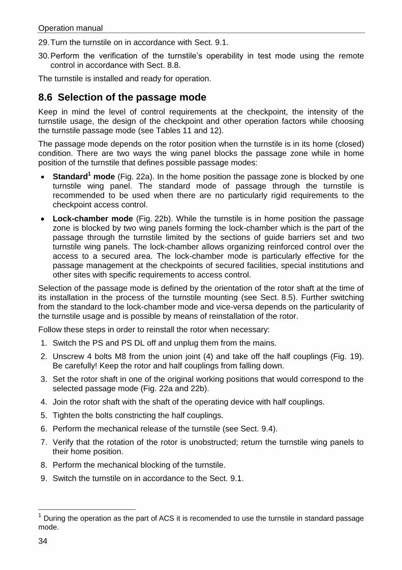
21. There is an alternative of laying out the power and control cables from above, through the top channel’s end face. Extract the necessary amount of plugs from the protective insertion panel, insert the cable bushings in the vacant holes and pull the cable through the bushings into the top channel.
22. Use the channel from the delivery set in order to lay out the cables atop to connect turnstiles standing close to each other (Fig. 21). Remove the protective inserts prior to the installation of the channels. The larger channel should be located above.
23. Perform the link-up to the contacts of the DIN-rail in accordance to the following turnstile and accessories connection scheme (Fig. 11):
indication cable (12);
turnstile power cable (13);
the cable of RC-panel (15) or the WRC unit;
the cable for the Fire Alarm unit (14) (in case the Fire Alarm unit isn’t the part of the package, make sure the «Fire Alarm» jumper is in its place);
jumpers «IMP / POT» DIN-rails (for the possible turnstile control mode);
cables for the accessories (if present).
Figure 21. Cable laying between two turnstiles
24. Verify the correctness and reliability of the electric linkage in accordance to the scheme of connection of turnstile and accessories (Fig. 11).
25. Stow the cables carefully inside the top channel upon the brackets, fix the cables with the brace rod from the delivery set. The cables shouldn’t interfere with the functioning of operating device and obstruct the shutting of the top channel’s cover.
26. For the unmotorized model of RTD-16.2 turnstile one can perform regulation of the damper if necessary (see Sect. 8.7).
27. Place the cover (9) upon the top channel(8):
Adjust the cover so that the logo of the PERCo company is situated above the post with barrier arms. For this reason there are stickers with arrows at the top channel’s end face and the end face of the cover; these arrows must coincide.
Lift the cover gently and put it upon the top channel from above. This procedure should be accomplished by two installers. If the turnstile has a canopy, the top channel’s cover may be temporarily placed upon the transverse parts of the canopy.
Screw four captive screws M5 (wrench SW4) up, the screws are fixing the cover of the top channel (Fig.18).
28. Switch the mechanical unlock system of the turnstile off (see Sect. 9.4).
Operation manual
34
29. Turn the turnstile on in accordance with Sect. 9.1.
30. Perform the verification of the turnstile’s operability in test mode using the remote control in accordance with Sect. 8.8.
The turnstile is installed and ready for operation.
8.6 Selection of the passage mode
Keep in mind the level of control requirements at the checkpoint, the intensity of the turnstile usage, the design of the checkpoint and other operation factors while choosing the turnstile passage mode (see Tables 11 and 12).
The passage mode depends on the rotor position when the turnstile is in its home (closed) condition. There are two ways the wing panel blocks the passage zone while in home position of the turnstile that defines possible passage modes:
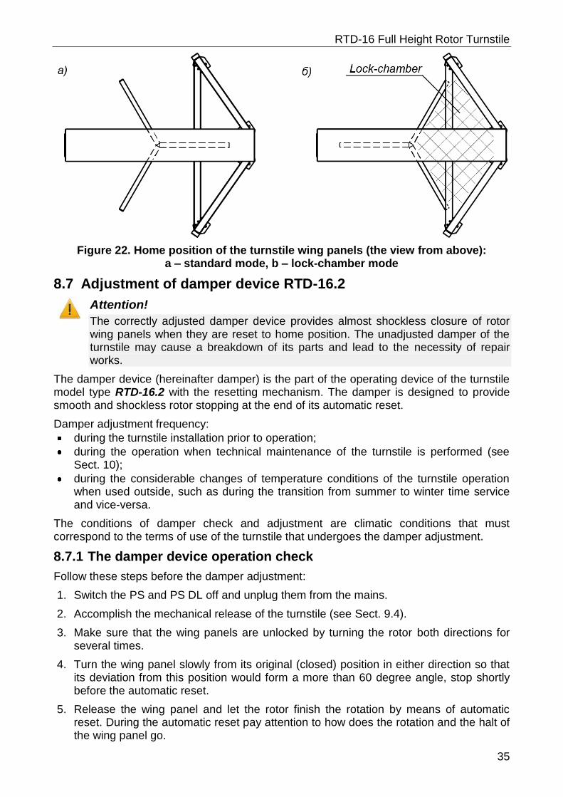
Standard1 mode (Fig. 22a). In the home position the passage zone is blocked by one turnstile wing panel. The standard mode of passage through the turnstile is recommended to be used when there are no particularly rigid requirements to the checkpoint access control.
Lock-chamber mode (Fig. 22b). While the turnstile is in home position the passage zone is blocked by two wing panels forming the lock-chamber which is the part of the passage through the turnstile limited by the sections of guide barriers set and two turnstile wing panels. The lock-chamber allows organizing reinforced control over the access to a secured area. The lock-chamber mode is particularly effective for the passage management at the checkpoints of secured facilities, special institutions and other sites with specific requirements to access control.
Selection of the passage mode is defined by the orientation of the rotor shaft at the time of its installation in the process of the turnstile mounting (see Sect. 8.5). Further switching from the standard to the lock-chamber mode and vice-versa depends on the particularity of the turnstile usage and is possible by means of reinstallation of the rotor.
Follow these steps in order to reinstall the rotor when necessary:
1. Switch the PS and PS DL off and unplug them from the mains.
2. Unscrew 4 bolts M8 from the union joint (4) and take off the half couplings (Fig. 19). Be carefully! Keep the rotor and half couplings from falling down.
3. Set the rotor shaft in one of the original working positions that would correspond to the selected passage mode (Fig. 22a and 22b).
4. Join the rotor shaft with the shaft of the operating device with half couplings.
5. Tighten the bolts constricting the half couplings.
6. Perform the mechanical release of the turnstile (see Sect. 9.4).
7. Verify that the rotation of the rotor is unobstructed; return the turnstile wing panels to their home position.
8. Perform the mechanical blocking of the turnstile.
9. Switch the turnstile on in accordance to the Sect. 9.1.
1 During the operation as the part of ACS it is recomended to use the turnstile in standard passage
mode.
RTD-16 Full Height Rotor Turnstile
35
Figure 22. Home position of the turnstile wing panels (the view from above): a – standard mode, b – lock-chamber mode
8.7 Adjustment of damper device RTD-16.2
Attention!
The correctly adjusted damper device provides almost shockless closure of rotor wing panels when they are reset to home position. The unadjusted damper of the turnstile may cause a breakdown of its parts and lead to the necessity of repair works.
The damper device (hereinafter damper) is the part of the operating device of the turnstile model type RTD-16.2 with the resetting mechanism. The damper is designed to provide smooth and shockless rotor stopping at the end of its automatic reset.
Damper adjustment frequency:
during the turnstile installation prior to operation;
during the operation when technical maintenance of the turnstile is performed (see Sect. 10);
during the considerable changes of temperature conditions of the turnstile operation when used outside, such as during the transition from summer to winter time service and vice-versa.
The conditions of damper check and adjustment are climatic conditions that must correspond to the terms of use of the turnstile that undergoes the damper adjustment.
8.7.1 The damper device operation check
Follow these steps before the damper adjustment:
1. Switch the PS and PS DL off and unplug them from the mains.
2. Accomplish the mechanical release of the turnstile (see Sect. 9.4).
3. Make sure that the wing panels are unlocked by turning the rotor both directions for several times.
4. Turn the wing panel slowly from its original (closed) position in either direction so that its deviation from this position would form a more than 60 degree angle, stop shortly before the automatic reset.
5. Release the wing panel and let the rotor finish the rotation by means of automatic reset. During the automatic reset pay attention to how does the rotation and the halt of the wing panel go.
Operation manual
36
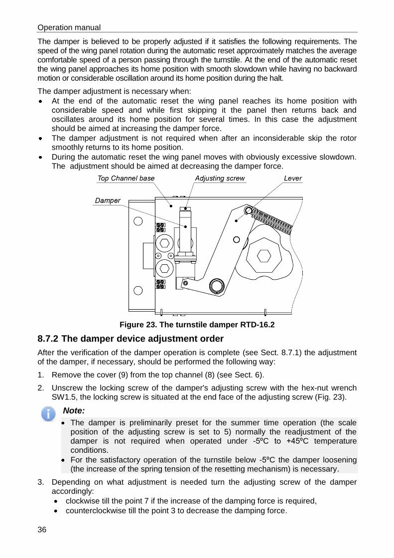
The damper is believed to be properly adjusted if it satisfies the following requirements. The speed of the wing panel rotation during the automatic reset approximately matches the average comfortable speed of a person passing through the turnstile. At the end of the automatic reset the wing panel approaches its home position with smooth slowdown while having no backward motion or considerable oscillation around its home position during the halt.
The damper adjustment is necessary when:
At the end of the automatic reset the wing panel reaches its home position with considerable speed and while first skipping it the panel then returns back and oscillates around its home position for several times. In this case the adjustment should be aimed at increasing the damper force.
The damper adjustment is not required when after an inconsiderable skip the rotor smoothly returns to its home position.
During the automatic reset the wing panel moves with obviously excessive slowdown. The adjustment should be aimed at decreasing the damper force.
Figure 23. The turnstile damper RTD-16.2
8.7.2 The damper device adjustment order
After the verification of the damper operation is complete (see Sect. 8.7.1) the adjustment of the damper, if necessary, should be performed the following way:
1. Remove the cover (9) from the top channel (8) (see Sect. 6).
2. Unscrew the locking screw of the damper's adjusting screw with the hex-nut wrench SW1.5, the locking screw is situated at the end face of the adjusting screw (Fig. 23).
Note:
The damper is preliminarily preset for the summer time operation (the scale position of the adjusting screw is set to 5) normally the readjustment of the damper is not required when operated under -5ºC to +45ºC temperature conditions.
For the satisfactory operation of the turnstile below -5ºC the damper loosening (the increase of the spring tension of the resetting mechanism) is necessary.
3. Depending on what adjustment is needed turn the adjusting screw of the damper accordingly:
clockwise till the point 7 if the increase of the damping force is required,
counterclockwise till the point 3 to decrease the damping force.
RTD-16 Full Height Rotor Turnstile
37
4. Repeat the check of the damper operation in accordance to the Sect. 8.7.1.
5. If necessary repeat the correction of the position of damper adjusting screw by means of rotation. Achieve the optimal resetting speed of the turnstile rotor.
Attention!
During the rearrangement of lever springs it is recommended to start with the removal of the spring hook in order to avoid the danger of injuries.
Depending on the conditions of use the necessity of the rearrangement of lever springs may appear. The rearrangement should be also consulted with the point 3 mentioned above. The goal to be achieved here is to increase or decrease the force of tension of the lever springs which translates into increase or decrease of the resetting speed of the turnstile rotor.
6. At the end of the regulation fix the position of the damper adjusting screw with the locking screw.
7. Install the cover upon the top channel (see Sect. 6).
8. Accomplish the mechanical locking of the turnstile (see Sect. 9.4).
Switch the turnstile on in accordance to the Sect. 9.1 in case it is necessary to continue the operation.
8.8 The turnstile performance check
8.8.1 Verification of the mechanical and emergency unblocking of the turnstile
1. Test the functioning of the mechanical release locks separately for both passage directions.
2. Put the rotor of the turnstile to home position. Switch the turnstile on (see Sect. 9.1).
3. Examine the functioning of the mechanical release sensors. Open the mechanical release lock for one of the passage directions and check the changes of light indication, the green arrow sign should appear at the indicator and be pointed towards the direction unlocked. The remote control panel led situated above the stop button should go out while the led above the button corresponding to the direction unlocked should light up. Perform the same sensor examination for the other passage direction.
4. Open both mechanical release locks and check the capability of turnstile rotation in different directions. Herewith the motorized version can reset the wing panels to home position automatically.
5. Close the mechanical release locks, it will block the turnstile rotation both directions. The indication will return to original condition, the indication situated at the turnstile post will show the red cross, the remote control panel will have a red led glowing above the stop sign.
6. Send a signal from the Fire Alarm device or disconnect the jumper between the clips 6 and 7 of the DIN-rail to check the performance of the Fire Alarm emergency unlock system. In this case the turnstile will become unlocked for the rotation in both directions; the indication of the remote control panel will correspond to the point 8 of the Table 8.
8.8.2 Verification of the turnstile performance in test mode
The verification is accomplished by means of pulse mode control of the turnstile exercised with the remote control panel.
Operation manual
38
1. Make sure the turnstile is mechanically locked against rotation in both directions (see Sect. 9.4).
2. Switch the turnstile on in accordance to Sect. 9.1. The RC-panel will emit a single audible signal during the turnstile activation.
3. Press briefly all three buttons at the remote control panel in order to switch the turnstile to the test mode. In this case the RC-panel (remote control panel) will emit a single audible signal, the order of RC-panel indication lights will be in accordance with the point 1 of the Table 8.
4. After the turnstile is switched to the test mode the order of RC-panel indication lights will be in accordance with point 2 of the Table 8. The turnstile power supply should not exceed 300 ma.
5. Push the left button (button LEFT) at the RC-panel. This will unlock the turnstile gates for the passage in the direction A, in this case the order of RC-panel indication lights will be in accordance to the point 3 of the Table 8. The electronics of the board will check whether the signals from this passage direction match. If the RC-panel doesn’t emit any audible signal in 10 seconds, then the sensors are in proper condition. In case the signals appear from the RC-panel buzzer, the faulty sensor can be found in accordance to the Table 9.
6. Turn the rotor of the turnstile in the direction unlocked to a 15° angle, in this case the rotor will shift to the next position while RC-panel buzzer will produce a signal in accordance to the Table 10. Monitor the correspondence of the number of audible signals and the rotor position in accordance to the table 10 while turning the rotor to a 360° angle. Press the STOP button at the RC-panel.
Note:
If there is more than a one audible signal, it stands for unnormalized condition of one of the sensors. In this case it is recommended to apply to the nearest service centre of PERCo for the advice.
7. Press the button RIGHT at the RC-panel and accomplish the same examination for the direction B. In this case the light indication of the RC-panel will correspond to the point 4 of the Table 8 and the sound signal order should correspond to the Table 10.
8. Press the STOP and LEFT buttons at the RC-panel at the same time.
9. For RTD-16.2. Turn the rotor in the direction A to a more than 50° angle, the following behavior should be supervised:
the RC-panel indication should correspond to the point 5 of Table 8;
the variation at the outlets PASS A(B) must correspond to the ongoing turn of the rotor;
the rotor must make a reset towards the passage;
continuous audible signal from RC-panel and the Ready signal tell about the absence of changes of signals from the turn sensors over a period of 10 seconds and about malfunction of the turn sensors chains accordingly.
For RTD-16.1. The rotor of the turnstile will start a continuous rotation in the direction A, the following behavior should be supervised:
the RC-panel indication should correspond to the point 5 of Table 8;
the variation at the outlets PASS A(B) must correspond to the current turn of the rotor;
the direction of the rotor rotation must correspond to the set direction;
the rotor has to be rotating smoothly and without jerks;
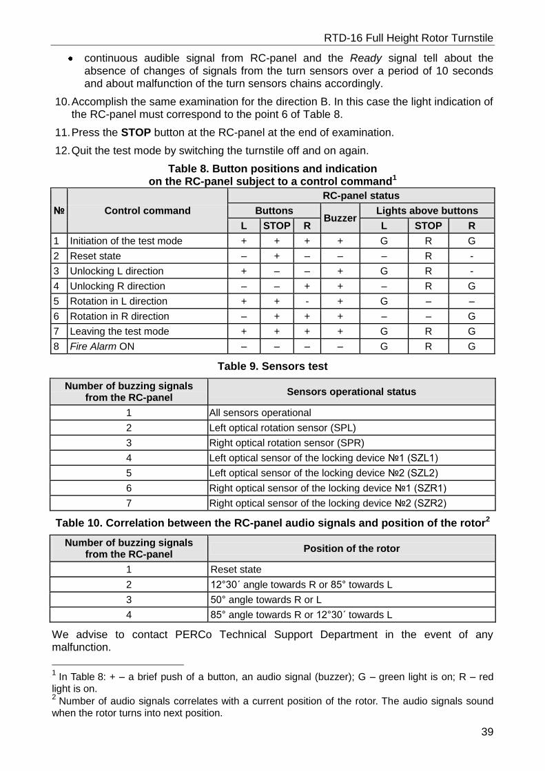
RTD-16 Full Height Rotor Turnstile
39
continuous audible signal from RC-panel and the Ready signal tell about the absence of changes of signals from the turn sensors over a period of 10 seconds and about malfunction of the turn sensors chains accordingly.
10. Accomplish the same examination for the direction B. In this case the light indication of the RC-panel must correspond to the point 6 of Table 8.
11. Press the STOP button at the RC-panel at the end of examination.
12. Quit the test mode by switching the turnstile off and on again.
Table 8. Button positions and indication on the RC-panel subject to a control command1
№ Control command
RC-panel status
Buttons Buzzer
Lights above buttons
L STOP R L STOP R
1 Initiation of the test mode + + + + G R G
2 Reset state – + – – – R -
3 Unlocking L direction + – – + G R -
4 Unlocking R direction – – + + – R G
5 Rotation in L direction + + - + G – –
6 Rotation in R direction – + + + – – G
7 Leaving the test mode + + + + G R G
8 Fire Alarm ON – – – – G R G
Table 9. Sensors test
Number of buzzing signals from the RC-panel
Sensors operational status
1 All sensors operational
2 Left optical rotation sensor (SPL)
3 Right optical rotation sensor (SPR)
4 Left optical sensor of the locking device №1 (SZL1)
5 Left optical sensor of the locking device №2 (SZL2)
6 Right optical sensor of the locking device №1 (SZR1)
7 Right optical sensor of the locking device №2 (SZR2)
Table 10. Correlation between the RC-panel audio signals and position of the rotor2
Number of buzzing signals from the RC-panel
Position of the rotor
1 Reset state
2 12°30´ angle towards R or 85° towards L
3 50° angle towards R or L
4 85° angle towards R or 12°30´ towards L
We advise to contact PERCo Technical Support Department in the event of any malfunction.
1 In Table 8: + – a brief push of a button, an audio signal (buzzer); G – green light is on; R – red
light is on. 2 Number of audio signals correlates with a current position of the rotor. The audio signals sound
when the rotor turns into next position.
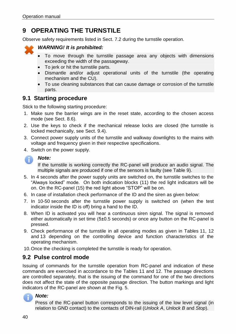
Operation manual
40
9 OPERATING THE TURNSTILE
Observe safety requirements listed in Sect. 7.2 during the turnstile operation.
WARNING! It is prohibited:
To move through the turnstile passage area any objects with dimensions exceeding the width of the passageway.
To jerk or hit the turnstile parts.
Dismantle and/or adjust operational units of the turnstile (the operating mechanism and the CU).
To use cleaning substances that can cause damage or corrosion of the turnstile parts.
9.1 Starting procedure
Stick to the following starting procedure:
1. Make sure the barrier wings are in the reset state, according to the chosen access mode (see Sect. 8.6).
2. Use the keys to check if the mechanical release locks are closed (the turnstile is locked mechanically, see Sect. 9.4).
3. Connect power supply units of the turnstile and walkway downlights to the mains with voltage and frequency given in their respective specifications.
4. Switch on the power supply.
Note:
If the turnstile is working correctly the RC-panel will produce an audio signal. The multiple signals are produced if one of the sensors is faulty (see Table 9).
5. In 4 seconds after the power supply units are switched on, the turnstile switches to the “Always locked” mode. On both indication blocks (11) the red light indicators will be on. On the RC-panel (15) the red light above “STOP” will be on.
6. In case of installation check performance of the ID and the siren as given below:
7. In 10-50 seconds after the turnstile power supply is switched on (when the test indicator inside the ID is off) bring a hand to the ID.
8. When ID is activated you will hear a continuous siren signal. The signal is removed either automatically in set time (5±0.5 seconds) or once any button on the RC-panel is pressed.
9. Check performance of the turnstile in all operating modes as given in Tables 11, 12 and 13 depending on the controlling device and function characteristics of the operating mechanism.
10. Once the checking is completed the turnstile is ready for operation.
9.2 Pulse control mode
Issuing of commands for the turnstile operation from RC-panel and indication of these commands are exercised in accordance to the Tables 11 and 12. The passage directions are controlled separately, that is the issuing of the command for one of the two directions does not affect the state of the opposite passage direction. The button markings and light indicators of the RC-panel are shown at the Fig. 5.
Note:
Press of the RC-panel button corresponds to the issuing of the low level signal (in relation to GND contact) to the contacts of DIN-rail (Unlock A, Unlock B and Stop).
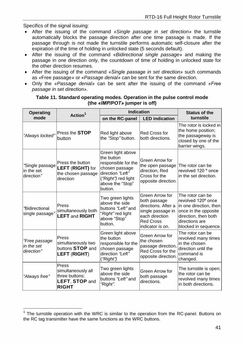
RTD-16 Full Height Rotor Turnstile
41
Specifics of the signal issuing:
After the issuing of the command «Single passage in set direction» the turnstile automatically blocks the passage direction after one time passage is made. If the passage through is not made the turnstile performs automatic self-closure after the expiration of the time of holding in unlocked state (5 seconds default).
After the issuing of the command «Bidirectional single passage» and making the passage in one direction only, the countdown of time of holding in unlocked state for the other direction resumes.
After the issuing of the command «Single passage in set direction» such commands as «Free passage» or «Passage denial» can be sent for the same direction.
Only the «Passage denial» can be sent after the issuing of the command «Free passage in set direction».
Table 11. Standard operating modes. Operation in the pulse control mode (the «IMP/POT» jumper is off)
Operating mode
Action1
Indication Status of the turnstile on the RC-panel LED indication
“Always locked” Press the STOP button
Red light above the “Stop” button.
Red Cross for both directions.
The rotor is locked in the home position; the passageway is closed by one of the barrier wings.
“Single passage in the set direction”
Press the button
LEFT (RIGHT) for
the chosen passage direction
Green light above the button responsible for the chosen passage direction “Left” (“Right”) red light above the “Stop” button.
Green Arrow for the open passage direction, Red Cross for the opposite direction.
The rotor can be revolved 120 º once in the set direction.
“Bidirectional single passage”
Press simultaneously both
LEFT and RIGHT
Two green lights above the side buttons “Left” and “Right” red light above “Stop” button.
Green Arrow for both passage directions. After a single passage in each direction Red Cross indicator is on.
The rotor can be revolved 120º once in one direction, then once in the opposite direction, then both directions are blocked in sequence.
“Free passage in the set direction”
Press simultaneously two
buttons STOP and
LEFT (RIGHT)
Green light above the button responsible for the chosen passage direction “Left” (“Right”)
Green Arrow for the chosen passage direction, Red Cross for the opposite direction.
The rotor can be revolved many times in the chosen direction until the command is changed.
“Always free”
Press simultaneously all three buttons:
LEFT, STOP and
RIGHT
Two green lights above the side buttons “Left” and “Right”.
Green Arrow for both passage directions.
The turnstile is open; the rotor can be revolved many times in both directions.
1 The turnstile operation with the WRC is similar to the operation from the RC-panel. Buttons on
the RC tag transmitter have the same functions as the WRC buttons.
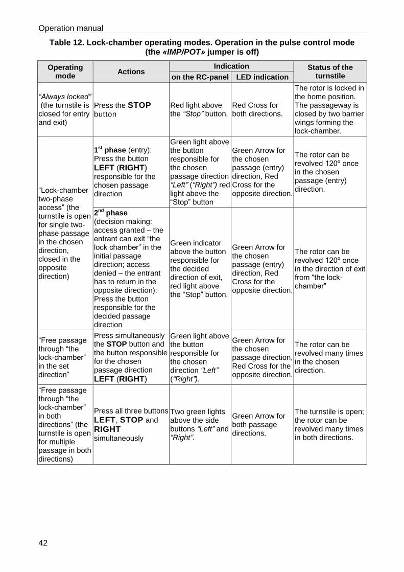
Operation manual
42
Table 12. Lock-chamber operating modes. Operation in the pulse control mode (the «IMP/POT» jumper is off)
Operating mode
Actions Indication Status of the
turnstile on the RC-panel LED indication
“Always locked” (the turnstile is closed for entry and exit)
Press the STOP button
Red light above the “Stop” button.
Red Cross for both directions.
The rotor is locked in the home position. The passageway is closed by two barrier wings forming the lock-chamber.
“Lock-chamber two-phase access” (the turnstile is open for single two-phase passage in the chosen direction, closed in the opposite direction)
1st phase (entry): Press the button
LEFT (RIGHT) responsible for the chosen passage direction
Green light above the button responsible for the chosen passage direction “Left” (“Right”) red light above the “Stop” button
Green Arrow for the chosen passage (entry) direction, Red Cross for the opposite direction.
The rotor can be revolved 120º once in the chosen passage (entry) direction.
2nd phase (decision making: access granted – the entrant can exit “the lock chamber” in the initial passage direction; access denied – the entrant has to return in the opposite direction): Press the button responsible for the decided passage direction
Green indicator above the button responsible for the decided direction of exit, red light above the “Stop” button.
Green Arrow for the chosen passage (entry) direction, Red Cross for the opposite direction.
The rotor can be revolved 120º once in the direction of exit from “the lock-chamber”
“Free passage through “the lock-chamber” in the set direction”
Press simultaneously the STOP button and the button responsible for the chosen passage direction
LEFT (RIGHT)
Green light above the button responsible for the chosen direction “Left” (“Right”).
Green Arrow for the chosen passage direction, Red Cross for the opposite direction.
The rotor can be revolved many times in the chosen direction.
“Free passage through “the lock-chamber” in both directions” (the turnstile is open for multiple passage in both directions)
Press all three buttons
LEFT, STOP and
RIGHT
simultaneously
Two green lights above the side buttons “Left” and “Right”.
Green Arrow for both passage directions.
The turnstile is open; the rotor can be revolved many times in both directions.
RTD-16 Full Height Rotor Turnstile
43
9.3 Potential control mode
The procedure of issuing of the turnstile control commands from ACS and the indication of the commands during the potential control mode is implemented in accordance to the Table 13. The passage directions are controlled separately, that is the issuing of the command for one of the two directions does not affect the state of the opposite passage direction.
In case of presence of the low-level signal at the contacts of corresponding passage direction which is being passed through at the moment, the turnstile will keep this direction open.
Table 13. Potential control mode (the «IMP/POT» jumper is on)
Operating mode Actions Indication Status of the turnstile
“Always locked”
The high-level signal at UnlockA and UnlockB contacts or the low-level signal at the Stop contact.
Red indicators for both directions are on.
The rotor is locked in original position.
«Free passage in the set direction»
The low-level signal at the contact of set direction. The high-level signal at the rest of the contacts.
Green indicator for set direction and red indicator for the opposite direction are on.
The rotor is unlocked for rotation in set direction until the command change.
«Bidirectional free passage»
The low-level signal at Unlock A and Unlock B contacts and the high-level signal at Stop contact.
Green indicators for both directions are on.
The rotor is unlocked for the rotation in both directions until the command change.
9.4 Emergency actions. For the emergency evacuation of people from the enterprise in case of fire, natural disaster or other alarm conditions, an emergency exit is required. Such an exit can be arranged by the full-height swing gate WHD-16.
The passage zone of RTD-16 can serve only as an additional emergency exit. In this case the turnstile rotor has to be unlocked in order to provide free passage.
The turnstile can be unlocked by means of:
control signal sent from the emergency unlock Fire Alarm device (see sect. 5.3.6);
unlocking the mechanical locks (used during electric grid power fluctuation or due to PS function failure etc.).
Take the following steps in order to unlock the turnstile mechanically:
1. Insert the key into the lock of mechanical unlocking situated at the side of the turnstile towards which the passage direction is to be unlocked.
2. Open the lock with the key by making one complete turn counterclockwise.
3. If the turnstile is switched on then:
The green arrow will be lit up at the indication block situated at the unlocked direction;
The red indicator above the STOP button at the remote control will be off, instead of this the green indicator situated above the button of the unlocked direction will be lit up.
4. Unlock the opposite direction of the rotor rotation the same way if necessary.
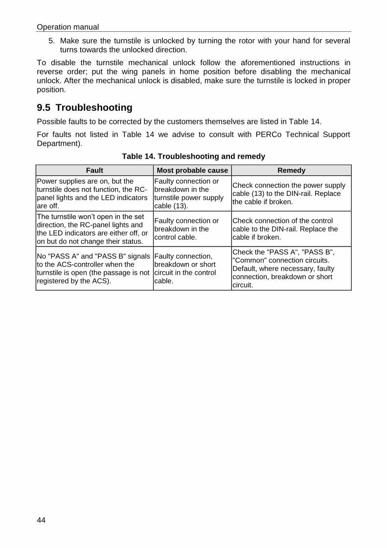
Operation manual
44
5. Make sure the turnstile is unlocked by turning the rotor with your hand for several turns towards the unlocked direction.
To disable the turnstile mechanical unlock follow the aforementioned instructions in reverse order; put the wing panels in home position before disabling the mechanical unlock. After the mechanical unlock is disabled, make sure the turnstile is locked in proper position.
9.5 Troubleshooting
Possible faults to be corrected by the customers themselves are listed in Table 14.
For faults not listed in Table 14 we advise to consult with PERCo Technical Support Department).
Table 14. Troubleshooting and remedy
Fault Most probable cause Remedy
Power supplies are on, but the turnstile does not function, the RC-panel lights and the LED indicators are off.
Faulty connection or breakdown in the turnstile power supply cable (13).
Check connection the power supply cable (13) to the DIN-rail. Replace the cable if broken.
The turnstile won’t open in the set direction, the RC-panel lights and the LED indicators are either off, or on but do not change their status.
Faulty connection or breakdown in the control cable.
Check connection of the control cable to the DIN-rail. Replace the cable if broken.
No "PASS A" and "PASS B" signals to the ACS-controller when the turnstile is open (the passage is not registered by the ACS).
Faulty connection, breakdown or short circuit in the control cable.
Check the "PASS A", "PASS B", "Common" connection circuits. Default, where necessary, faulty connection, breakdown or short circuit.
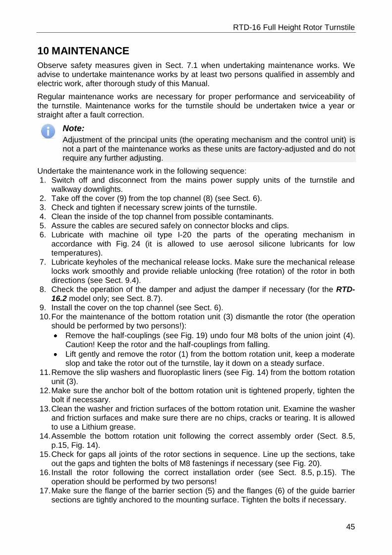
RTD-16 Full Height Rotor Turnstile
45
10 MAINTENANCE
Observe safety measures given in Sect. 7.1 when undertaking maintenance works. We advise to undertake maintenance works by at least two persons qualified in assembly and electric work, after thorough study of this Manual.
Regular maintenance works are necessary for proper performance and serviceability of the turnstile. Maintenance works for the turnstile should be undertaken twice a year or straight after a fault correction.
Note:
Adjustment of the principal units (the operating mechanism and the control unit) is not a part of the maintenance works as these units are factory-adjusted and do not require any further adjusting.
Undertake the maintenance work in the following sequence: 1. Switch off and disconnect from the mains power supply units of the turnstile and
walkway downlights. 2. Take off the cover (9) from the top channel (8) (see Sect. 6). 3. Check and tighten if necessary screw joints of the turnstile. 4. Clean the inside of the top channel from possible contaminants. 5. Assure the cables are secured safely on connector blocks and clips. 6. Lubricate with machine oil type I-20 the parts of the operating mechanism in
accordance with Fig. 24 (it is allowed to use aerosol silicone lubricants for low temperatures).
7. Lubricate keyholes of the mechanical release locks. Make sure the mechanical release locks work smoothly and provide reliable unlocking (free rotation) of the rotor in both directions (see Sect. 9.4).
8. Check the operation of the damper and adjust the damper if necessary (for the RTD-16.2 model only; see Sect. 8.7).
9. Install the cover on the top channel (see Sect. 6). 10. For the maintenance of the bottom rotation unit (3) dismantle the rotor (the operation
should be performed by two persons!):
Remove the half-couplings (see Fig. 19) undo four M8 bolts of the union joint (4). Caution! Keep the rotor and the half-couplings from falling.
Lift gently and remove the rotor (1) from the bottom rotation unit, keep a moderate slop and take the rotor out of the turnstile, lay it down on a steady surface.
11. Remove the slip washers and fluoroplastic liners (see Fig. 14) from the bottom rotation unit (3).
12. Make sure the anchor bolt of the bottom rotation unit is tightened properly, tighten the bolt if necessary.
13. Clean the washer and friction surfaces of the bottom rotation unit. Examine the washer and friction surfaces and make sure there are no chips, cracks or tearing. It is allowed to use a Lithium grease.
14. Assemble the bottom rotation unit following the correct assembly order (Sect. 8.5, p.15, Fig. 14).
15. Check for gaps all joints of the rotor sections in sequence. Line up the sections, take out the gaps and tighten the bolts of M8 fastenings if necessary (see Fig. 20).
16. Install the rotor following the correct installation order (see Sect. 8.5, p.15). The operation should be performed by two persons!
17. Make sure the flange of the barrier section (5) and the flanges (6) of the guide barrier sections are tightly anchored to the mounting surface. Tighten the bolts if necessary.
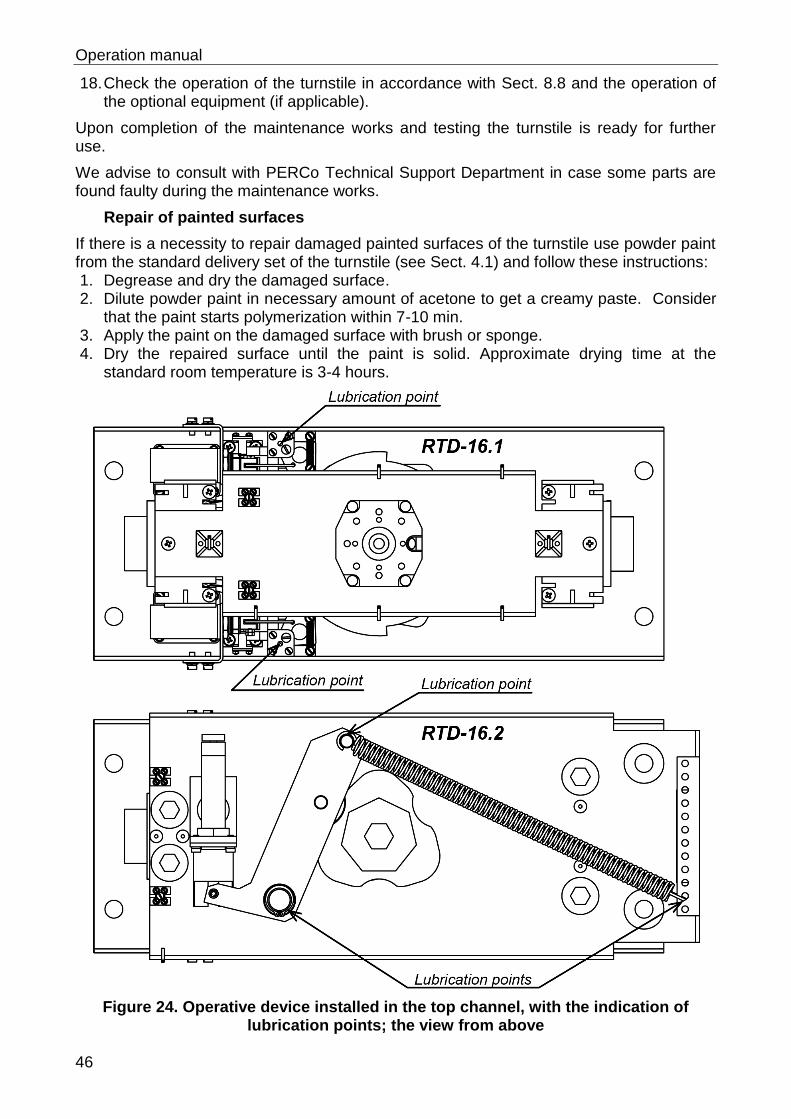
Operation manual
46
18. Check the operation of the turnstile in accordance with Sect. 8.8 and the operation of the optional equipment (if applicable).
Upon completion of the maintenance works and testing the turnstile is ready for further use.
We advise to consult with PERCo Technical Support Department in case some parts are found faulty during the maintenance works.
Repair of painted surfaces
If there is a necessity to repair damaged painted surfaces of the turnstile use powder paint from the standard delivery set of the turnstile (see Sect. 4.1) and follow these instructions: 1. Degrease and dry the damaged surface. 2. Dilute powder paint in necessary amount of acetone to get a creamy paste. Consider
that the paint starts polymerization within 7-10 min. 3. Apply the paint on the damaged surface with brush or sponge. 4. Dry the repaired surface until the paint is solid. Approximate drying time at the
standard room temperature is 3-4 hours.
Figure 24. Operative device installed in the top channel, with the indication of lubrication points; the view from above
RTD-16 Full Height Rotor Turnstile
47
11 TRANSPORTATION AND STORAGE
The turnstile in the original package should be transported in closed freight containers or closed type cargo transport units (railway carriages, containers, closed cars, ship’s holds etc.).
During storage and transportation the boxes can be stacked no more than 2 layers high. Box dimensions and weight are given in Table 4.
The turnstile should be stored indoors at ambient temperatures between -40°C to +50°C and relative air humidity up to 98% at +25°C. The storage facilities should be free from acid, alkalis and corrosive gases.
If prior to installation the turnstile was transported or stored at below-zero temperatures or high air humidity, it should be kept in package for no less than 24 hours under operation conditions given in Sect. 2.
Operation manual
48
APPENDIX 1. Algorithm of control signals generation in pulse control mode
The command is an active edge of the signal (the transition of the signal from high level to low level) at the appropriate contact relative to the levels of the signals at the other contacts.
Note. For the RC-panel:
Active front – the moment of pushing a respective button on the RC-panel; Low level – the respective button on the RC-panel is pushed; High level – the respective button on the RC-panel is not pushed.
By feeding a low-level signal relative to the GND contact to the DIN-rail contacts Unlock A, Stop and Unlock B, the following commands can be generated.
"Always locked" (the turnstile is closed for entry and exit) – the active front at the Stop and a high-level signal at the Unlock A and Unlock B contacts. Both directions are closed by this command.
"Single passage in direction A" (the turnstile is open for a single passage of one person in direction A) – the active front at the Unlock A contact and a high-level signal at the Stop and Unlock B contacts. This command opens direction A either for 5 seconds, or until completion of the passage, or until the "Always locked" command is given, whereas status of direction B will not change. The command is ignored if it is received at the moment when direction A is in the "Always free" mode.
"Single passage in direction B" (the turnstile is open for a single passage of one person in direction B) – the active front at the Unlock B contact and a high-level signal at the Stop and Unlock A contacts. This command opens direction B either for 5 seconds, or until completion of the passage, or until the "Always locked" command is given, whereas status of direction A will not change. The command is ignored if it is received at the moment when direction B is in the "Always free" mode.
"Bidirectional single passage" (the turnstile is open for a single passage of one person in each direction) – the active front at the Unlock A contact opens direction A with a high-level signal at the Stop contact, and the active front at the Unlock B contact opens direction B with a high-level signal at the Stop contact, sequence order of the fronts being of no difference. This command opens both directions, each for either 5 seconds, or until completion of the respective passage, or until the "Always locked" command is received. The command is ignored for either direction if it is received when this direction is in the "Always free" mode.
"Free passage in direction A" (the turnstile is open for multiple passage in direction A) – an active front at the Unlock A contact, a low-level signal at the Stop and a high-level signal at the Unlock B contact, or the active front at the Stop contact, a low-level signal at the Unlock A contact and a high-level signal at the Unlock B contact. This command opens direction A until the "Always locked" command is received, whereas status of direction B will not change.
Note:
When the passage direction B is open and the command “Free passage in direction A” is issued at once the time slot between the edges of the signals Stop and Unlock A should not exceed 30 ms (which corresponds to simultaneous press of the buttons). Otherwise the command may be adopted as “Always locked” and the direction B may be blocked. This note is also relevant for the situation when the command "Free passage in direction B" is issued (taking into account the change of direction indexes).
RTD-16 Full Height Rotor Turnstile
49
"Free passage in direction B" (the turnstile is open for multiple passage in direction B) – the active front at the Unlock B contact, a low-level signal at the Stop contact and high-level contact at the Unlock A contact, or the active front at the contact Stop, a low-level signal at the Unlock B contact and a high-level signal at the Unlock A. This command opens direction B until the "Always locked" command is received, whereas status of direction A will not change.
"Always free" (the turnstile is open for multiple passages in both directions) – the active front at the Unlock A contact with a low-level signal at the Stop contact and the active front at the Unlock B contact with a low-level signal at the Stop contact, or the active front at the Stop contact with a low-level signal at the Unlock A and Unlock B contacts, sequence order of the fronts being of no difference. This command opens both directions until the "Always locked" command is received.
APPENDIX 2. Algorithm of control signals generation in potential control mode
Note. For ACS-controller outputs:
Low level – output relay contacts are closed, or the output transistor is open; High level –output relay contacts are open, or the output transistor is closed.
"Both directions closed" (the turnstile is locked for entry and exit) – a high-level signal at the Unlock A, Unlock B contacts or a low-level signal at the Stop contact. This command closes both directions.
"Direction A open" (the turnstile is open for passage in direction A) – a low-level signal at the Unlock A contact and a high-level signal at the Stop, Unlock B contacts. This command opens direction A until a low-level signal is removed from the Unlock A contact, or the "Both directions closed" command is received, whereas status of direction B will not change.
"Direction B open" (the turnstile is open for passage in direction B) – a low-level signal at the Unlock B contact and a high-level at the Stop, Unlock A contacts. This command opens direction B until a low-level signal is removed from the Unlock B contact, or the "Both directions closed" command is received, whereas status of direction A will not change.
"Both directions open" (the turnstile is open in for passage both directions) – a low-level signal at the Unlock A and Unlock B contacts and a high-level signal at the Stop signal. This command opens both directions until a low-level signal is removed from either Unlock A or Unlock B contact, or the "Both directions closed" command is received.
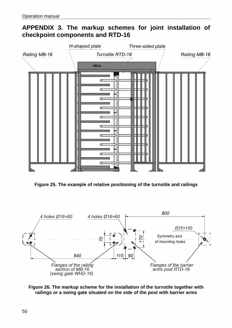
Operation manual
50
APPENDIX 3. The markup schemes for joint installation of checkpoint components and RTD-16
Figure 25. The example of relative positioning of the turnstile and railings
Figure 26. The markup scheme for the installation of the turnstile together with railings or a swing gate situated on the side of the post with barrier arms
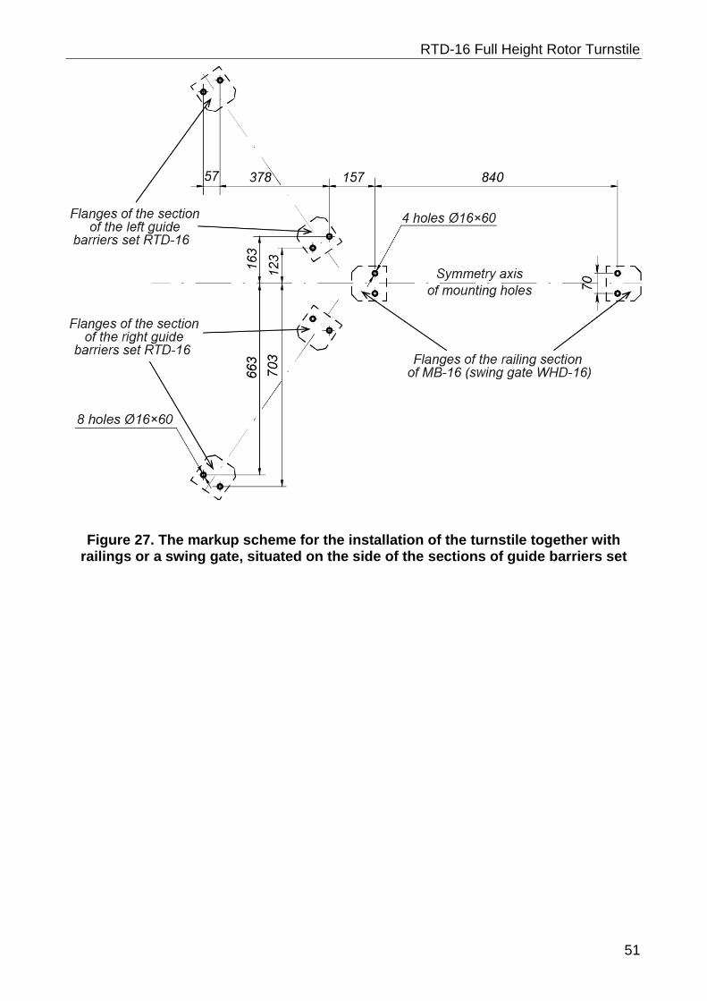
RTD-16 Full Height Rotor Turnstile
51
Figure 27. The markup scheme for the installation of the turnstile together with railings or a swing gate, situated on the side of the sections of guide barriers set

PERCo
Polytechnicheskaya str., 4, block 2 194021, Saint Petersburg
Russia
Tel: +7 812 247 04 64
E-mail: [email protected] [email protected]
www.perco.com

www.perco.com


