Full lift safety valve with spring loading. (AIT) The valve works as an automatic pressure releasing regulator activated by the static pressure existing at the entrance to the valve and is characterized by its ability to open instantly and totally. Design in accordance with “International Standard ISO 4126-1 Safety Valves”. In accordance with the requirements of directive 97/23/EC. EC valve verification certified by: TÜV Internacional Grupo TÜV Rheinland, S.L. EC 0035. Type (Module D) EC examination report nº 33530455 certified by: TÜV Internacional Grupo TÜV Rheinland, S.L. In compliance with the ATEX 94/9/CE directive “Protective equipment and systems for use in potentially explosive atmospheres”. Other authorisations: ISCIR, ITI, NASTHOL,...etc. Specifications ― 90° angular flow. ― Activated by direct action helicoid spring. ― Simplicity of construction ensuring minimum maintenance. ― Materials carefully selected for their resistance to corrosion. ― Internal body designed to offer favourable flow profile. ― Sealing surfaces balanced and making them extremely tightness, even exceeding EN 12266-1 requeriments. ― Great discharge capacity. For liquids typically used with openings similar to proportional safety valves. ― Auto-centering plug. ― Totally precise open and close. ― All the valves are supplied sealed at the set pressure requested, simulating operational conditions, and are vigorously tested. ― All components are numbered, registered and checked. If requested in advance, material, casting, test and efficiency certificates will be enclosed with the valve, and the instruction manual, in accordance with P.E.D.97/23 EC. IMPORTANT 1.- Fluorelastomer (Vitón) seals, Silicone’s rubber, PTFE (Teflón) o Perfluorelastomer (FFKM). Achieving leakage levels less than EN Depending on demand: 1. Buna-nitryls seals, Butyl, Natural rubber, E.P.D.M., Chlorosulphonate polyethylene (Hypalon), Neoprene, etc. 2. Possibility of manufacture in other types of material, for use in special working conditions (high temperatures, fluids, etc.). Model 695 Model 995 Model 895 Model 694 EP EP EP EP ES ES ES ES AP AP AP AP AS AS AS AS Model 695 Model 895 Model 995 Model 694 RANGE OF APPLICATION FOR THE SEALS FLUID SET PRESSURE IN bar Saturated steam Liquids and gases SEALS TEMPERATURE IN °C MINIMUM MAXIMUM Silicone’s rubber S -50 200 Fluorelastomer (Vitón) V -20 220 PTFE (Teflón) T -196 260 Perfluorelastomer (FFKM) K -10 250 S V S 1,80 4,80 20,00 30,00 36,01 45,00 144,0 0,20 V T K T K
Transcript
Full lift safety valvewith spring loading.
(AIT)
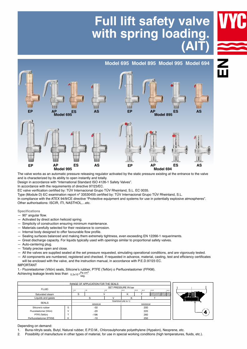
The valve works as an automatic pressure releasing regulator activated by the static pressure existing at the entrance to the valve and is characterized by its ability to open instantly and totally.Design in accordance with “International Standard ISO 4126-1 Safety Valves”.In accordance with the requirements of directive 97/23/EC.EC valve verification certified by: TÜV Internacional Grupo TÜV Rheinland, S.L. EC 0035. Type (Module D) EC examination report nº 33530455 certified by: TÜV Internacional Grupo TÜV Rheinland, S.L. In compliance with the ATEX 94/9/CE directive “Protective equipment and systems for use in potentially explosive atmospheres”.Other authorisations: ISCIR, ITI, NASTHOL,...etc.
Specifications ― 90° angular flow. ― Activated by direct action helicoid spring. ― Simplicity of construction ensuring minimum maintenance. ― Materials carefully selected for their resistance to corrosion. ― Internal body designed to offer favourable flow profile. ― Sealing surfaces balanced and making them extremely tightness, even exceeding EN 12266-1 requeriments. ― Great discharge capacity. For liquids typically used with openings similar to proportional safety valves. ― Auto-centering plug. ― Totally precise open and close. ― All the valves are supplied sealed at the set pressure requested, simulating operational conditions, and are vigorously tested. ― All components are numbered, registered and checked. If requested in advance, material, casting, test and efficiency certificates will be enclosed with the valve, and the instruction manual, in accordance with P.E.D.97/23 EC.
IMPORTANT1.- Fluorelastomer (Vitón) seals, Silicone’s rubber, PTFE (Teflón) o Perfluorelastomer (FFKM).Achieving leakage levels less than
EN
Depending on demand:1. Buna-nitryls seals, Butyl, Natural rubber, E.P.D.M., Chlorosulphonate polyethylene (Hypalon), Neoprene, etc.2. Possibility of manufacture in other types of material, for use in special working conditions (high temperatures, fluids, etc.).
Model 695
Model 995
Model 895
Model 694
EP
EP EP
EPES
ES ES
ESAP
AP AP
APAS
AS AS
AS
Model 695 Model 895 Model 995 Model 694
RANGE OF APPLICATION FOR THE SEALS
FLUID SET PRESSURE IN bar
Saturated steamLiquids and gases
SEALS TEMPERATURE IN °CMINIMUM MAXIMUM
Silicone’s rubber S -50 200Fluorelastomer (Vitón) V -20 220
PTFE (Teflón) T -196 260Perfluorelastomer (FFKM) K -10 250
S VS
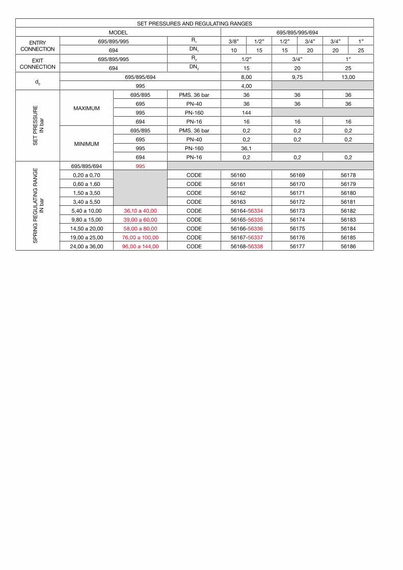
1,80 4,80 20,00 30,00 36,01 45,00 144,00,20
VTK
TK
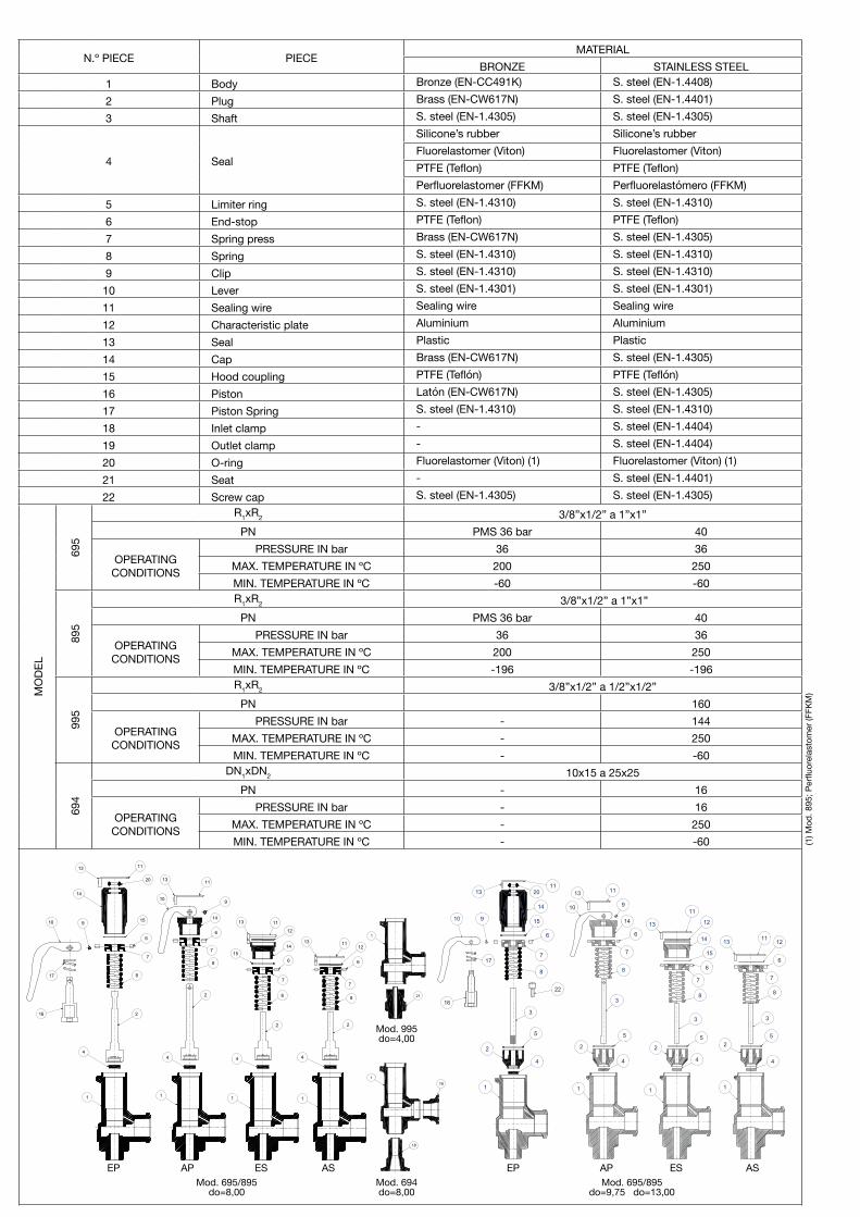
N.º PIECE PIECEMATERIAL
BRONZE STAINLESS STEEL1 Body Bronze (EN-CC491K) S. steel (EN-1.4408) 2 Plug Brass (EN-CW617N) S. steel (EN-1.4401)3 Shaft S. steel (EN-1.4305) S. steel (EN-1.4305)
5 Limiter ring S. steel (EN-1.4310) S. steel (EN-1.4310)6 End-stop PTFE (Teflon) PTFE (Teflon)7 Spring press Brass (EN-CW617N) S. steel (EN-1.4305)8 Spring S. steel (EN-1.4310) S. steel (EN-1.4310)9 Clip S. steel (EN-1.4310) S. steel (EN-1.4310)10 Lever S. steel (EN-1.4301) S. steel (EN-1.4301) 11 Sealing wire Sealing wire Sealing wire12 Characteristic plate Aluminium Aluminium13 Seal Plastic Plastic14 Cap Brass (EN-CW617N) S. steel (EN-1.4305) 15 Hood coupling PTFE (Teflón) PTFE (Teflón)16 Piston Latón (EN-CW617N) S. steel (EN-1.4305)17 Piston Spring S. steel (EN-1.4310) S. steel (EN-1.4310)18 Inlet clamp - S. steel (EN-1.4404)19 Outlet clamp - S. steel (EN-1.4404)20 O-ring Fluorelastomer (Viton) (1) Fluorelastomer (Viton) (1)21 Seat - S. steel (EN-1.4401)22 Screw cap S. steel (EN-1.4305) S. steel (EN-1.4305)
MO
DEL
695
R1xR2 3/8”x1/2” a 1”x1”PN PMS 36 bar 40
OPERATINGCONDITIONS
PRESSURE IN bar 36 36MAX. TEMPERATURE IN ºC 200 250MIN. TEMPERATURE IN ºC -60 -60
895
R1xR2 3/8”x1/2” a 1”x1”PN PMS 36 bar 40
OPERATINGCONDITIONS
PRESSURE IN bar 36 36MAX. TEMPERATURE IN ºC 200 250MIN. TEMPERATURE IN ºC -196 -196
995
R1xR2 3/8”x1/2” a 1/2”x1/2”PN 160
OPERATINGCONDITIONS
PRESSURE IN bar - 144MAX. TEMPERATURE IN ºC - 250MIN. TEMPERATURE IN ºC - -60
694
DN1xDN2 10x15 a 25x25PN - 16
OPERATINGCONDITIONS
PRESSURE IN bar - 16MAX. TEMPERATURE IN ºC - 250MIN. TEMPERATURE IN ºC - -60 (1
) Mod
. 895
; Per
fluor
elas
tom
er (F
FKM
)
EP EPAP APES ESAS AS
1
15
4
2 16
17
10
11
20
13
14
9
6
8
7
910
6
7
8
2
4
1
1113
14
1
4
2
8
7
615
14
1113
12
1
4
2
8
7
6
121113
1
21
1
18
19
Mod. 695/895do=8,00
Mod. 995do=4,00
Mod. 694do=8,00
Mod. 695/895do=9,75 do=13,00
1
4
2
5
8
7
6
15
14
2011
13
3
22
10 9
17
16
1113
10 9
14
6
7
8
3
5
2
4
1 1
4
2
5
3
8
7
6
15
14
12
11
13
1
4
25
3
8
7
6
121113
Full lift safety valve with spring loading (AIT) version EP.1. Disassembly and assembly1.1 DisassmblyTo replace the spring (8) or clean any of the internal components of the valve, proceed in the following manner:A - Cut the seal thread (11) with pliers.B - Withdraw the fastener (9), using a punching tool, until the lever (10) comes free.C - Unscrew and extract the hood (14).D - Unscrew the piston (16) from the rod (3 ) and then the screw cap (22).E - Holding the rod (3), unscrew the spring press (7) until you note a releasing of the spring (8).F - Extract the spring (8).1.2 AssemblyA - Enter the spring (8) through the upper part of the rod (3).B - Screw the spring press (7) holding the rod (3) and the screw cap (22).C - Adjust the set pressure with the spring press (7).D - Screw the piston (16) to the rod (3).E - Screw the hood (14).F - Place the lever (10) and fix it with the fastener (9).2. Adjusting the firing pressureA - Proceed according to points 1.1.A, 1.1.B, 1.1.C, 1.1.D, 1.1.E.B - Proceed according to points 1.2.C, 1.2.D, 1.1.E, 1.1.F.
Full lift safety valve with spring loading (AIT) version AP.1. Disassembly and assembly1.1 DisassmblyTo replace the spring (8) or clean any of the internal components of the valve, proceed in the following manner:A - Cut the seal thread (11) with pliers.B - Withdraw the clip (9), using a punching tool, until the lever (10) comes free.C - Unscrew and extract the hood (14).D - Holding the rod (3), unscrew the spring press (7) until you note a releasing of the spring (8).E - Extract the spring (8).1.2 Assembly1.2 AssemblyA - Enter the spring (8) through the upper part of the rod (3).B - Screw the spring press (7) holding the rod (3).C - Adjust the set pressure with the spring press (7).D - Screw the hood (14).E - Place the lever (10) and fix it with the fastener (9)2. Adjusting the firing pressureA - Proceed according to points 1.1.A, 1.1.B, 1.1.C, 1.1.D.B - Proceed according to points 1.2.C, 1.2.D, 1.1.E.
Full lift safety valve with spring loading (AIT) version ES.1. Disassembly and assembly1.1 DisassmblyTo replace the spring (8) or clean any of the internal components of the valve, proceed in the following manner:A - Cut the seal thread (11) with pliers and extract the characteristic plate (12).B - Unscrew and extract the hood (14).C - Holding the rod (3), unscrew the spring press (7) until you note a releasing of the spring (8).D - Extract the spring (8).1.2 AssemblyA - Enter the spring (8) through the upper part of the rod (3).B - Screw the spring press (7) holding the rod (3).C - Adjust the set pressure with the spring press (7).D - Screw the hood (14).2. Adjusting the firing pressureA - Proceed according to points 1.1.A, 1.1.B, 1.1.C.B - Proceed according to points 1.2.C, 1.2.D..
Full lift safety valve with spring loading (AIT) version AS.1. Disassembly and assembly1.1 DisassmblyTo replace the spring (8) or clean any of the internal components of the valve, proceed in the following manner:A - Cut the seal thread (11) with pliers and extract the characteristic plate (12).B - Holding the rod (3), unscrew the spring press (7) until you note a releasing of the spring (8).C - Extract the spring (8).1.2 AssemblyA - Enter the spring (8) through the upper part of the rod (3).B - Screw the spring press (7) holding the rod (3).C - Adjust the set pressure with the spring press (7).2. Adjusting the firing pressureA - Proceed according to points 1.1.A, 1.1.B.B - Proceed according to points 1.2.C.
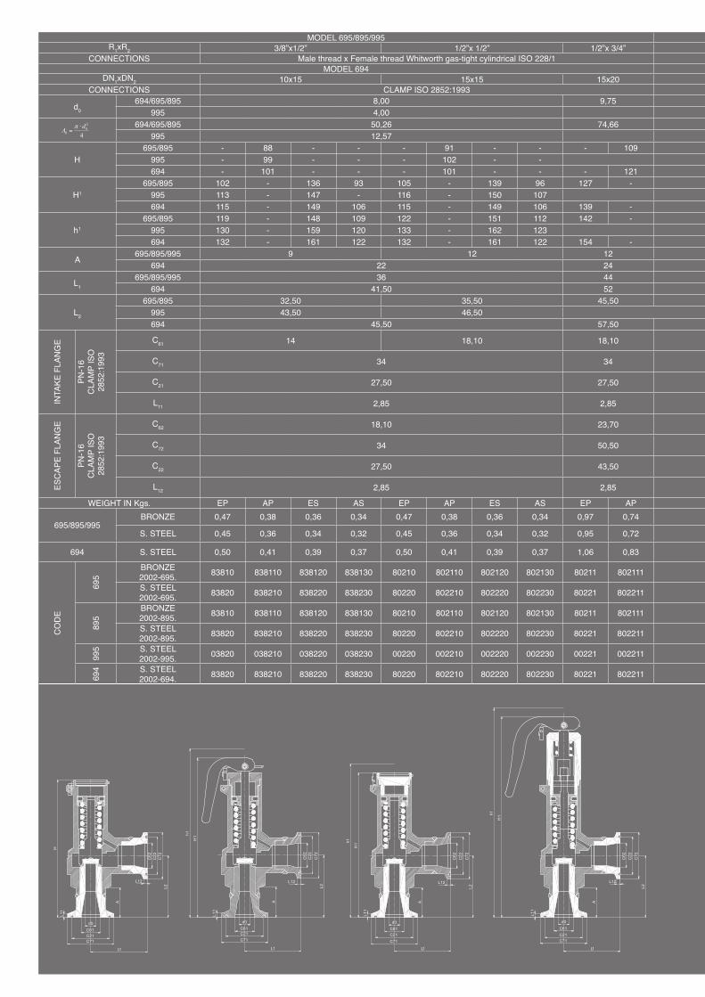
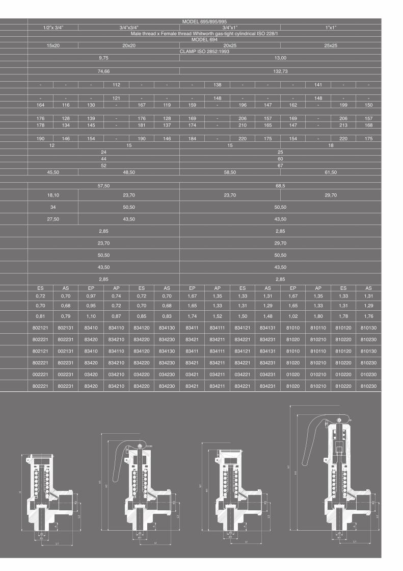
MODEL 695/895/995 MODEL 695/895/995R1xR2 3/8”x1/2” 1/2”x 1/2” 1/2”x 3/4” 1/2”x 3/4” 3/4”x3/4” 3/4”x1” 1”x1”
CONNECTIONS Male thread x Female thread Whitworth gas-tight cylindrical ISO 228/1 Male thread x Female thread Whitworth gas-tight cylindrical ISO 228/1MODEL 694 MODEL 694
DN1xDN2 10x15 15x15 15x20 15x20 20x20 20x25 25x25CONNECTIONS CLAMP ISO 2852:1993 CLAMP ISO 2852:1993
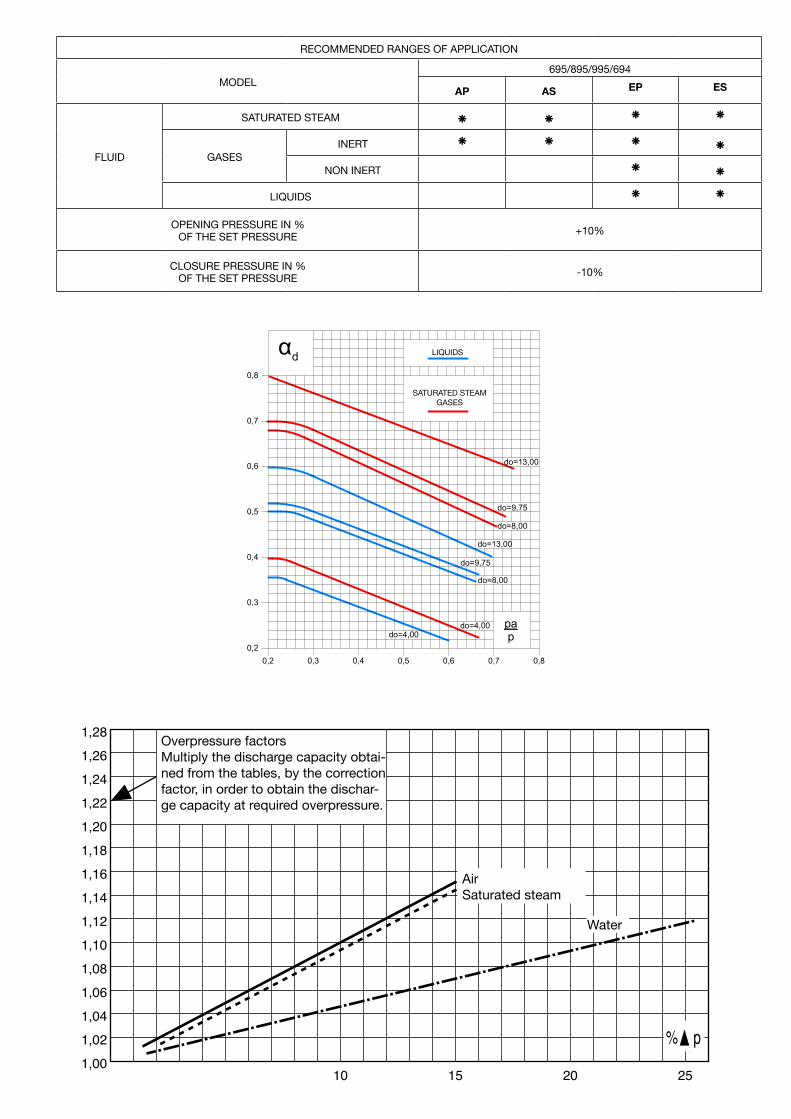
Overpressure factorsMultiply the discharge capacity obtai-ned from the tables, by the correction factor, in order to obtain the dischar-ge capacity at required overpressure.
0,8
0,7
0,6
0,5
0,4
0,3
0,20,2 0,3 0,4 0,5 0,6 0,7 0,8
αd LÍQUIDOS
VAPOR SATURADOGASES
do=13,00
do=9,75
do=8,00
do=13,00
do=9,75
do=8,00
do=4,00do=4,00
pap
LIQUIDS
SATURATED STEAMGASES
AirSaturated steam
Water
Informative brochure, without obligation and subject to our General Sales Conditions.
+34 93 735 76 90 +34 93 735 81 35 [email protected] 89132/14Avenc del Daví, 22 Pol. Ind. Can Petit 08227 TERRASSA (Barcelona) SPAINwww.vycindustrial.com
![· el ep uqpeuuo}l]! el uaua!luoo enb saluqpadxa '6L0t p eluenp ap eweffid pp el pp e 0Jaua ep lap q e sowospe soo!lqod ep uppel!oedeo Jod sewqd!p ap e6êJ1ue el e opeuopelêJ 01](https://static.documents.pub/doc/80x56/5fc5a16cbc1a1842c43de217/el-ep-uqpeuuol-el-uaualuoo-enb-saluqpadxa-6l0t-p-eluenp-ap-eweffid-pp-el-pp.jpg)


