12
ATLAS ® FM ™ FULL METRIC INSERTS 210 R EV . 611 CATALOG

ATLAS® FM™ FULL METRIC INSERTS
210RE v. 611
CATALOG
FM-2
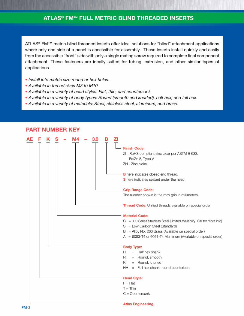
AE F K S – M4 – 3.0 B ZI
Finish Code:ZI - RoHS compliant zinc clear per ASTM B 633, Fe/Zn 8, Type VZN - Zinc nickel
B here indicates closed end thread.S here indicates sealant under the head.
Grip Range Code:The number shown is the max grip in millimeters.
Thread Code. Unified threads available on special order.
Material Code:C = 300 Series Stainless Steel (Limited availablity. Call for more info)S = Low Carbon Steel (Standard)B = Alloy No. 260 Brass (Available on special order)A = 6053-T4 or 6061-T4 Aluminum (Available on special order)
Body Type:H = Half hex shankR = Round, smoothK = Round, knurledHH = Full hex shank, round counterbore
Head Style:F = FlatT = ThinC = Countersunk
Atlas Engineering.
PART NUMBER KEY
ATLAS® FM™ metric blind threaded inserts offer ideal solutions for “blind” attachment applications where only one side of a panel is accessible for assembly. These inserts install quickly and easily from the accessible “front” side with only a single mating screw required to complete final component attachment. These fasteners are ideally suited for tubing, extrusion, and other similar types of applications.
• Install into metric size round or hex holes.• Available in thread sizes M3 to M10.• Available in a variety of head styles: Flat, thin, and countersunk.• Available in a variety of body types: Round (smooth and knurled), half hex, and full hex.• Available in a variety of materials: Steel, stainless steel, aluminum, and brass.
ATLAS® FM™ FULL METRIC BLIND THREADED INSERTS
FM-3
INDEX
ATLAS® FM™ FULL METRIC BLIND THREADED INSERTS
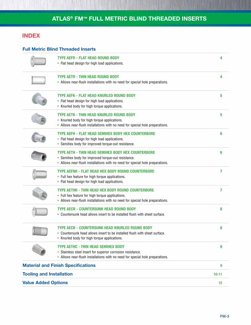
Full Metric Blind Threaded Inserts
Type AeFR - FLAT HeAD ROUND BODy 4• Flat head design for high load applications.
Type AeTR - THIN HeAD ROUND BODy 4• Allows near-flush installations with no need for special hole preparations.
Type AeFK - FLAT HeAD KNURLeD ROUND BODy 5• Flat head design for high load applications. • Knurled body for high torque applications.
Type AeTK - THIN HeAD KNURLeD ROUND BODy 5• Knurled body for high torque applications.• Allows near-flush installations with no need for special hole preparations.
Type AeFH - FLAT HeAD SeMIHeX BODy HeX COUNTeRBORe 6• Flat head design for high load applications.• Semihex body for improved torque-out resistance.
Type AeTH - THIN HeAD SeMIHeX BODy HeX COUNTeRBORe 6• Semihex body for improved torque-out resistance.• Allows near-flush installations with no need for special hole preparations.
Type AeFHH - FLAT HeAD HeX BODy ROUND COUNTeRBORe 7• Full hex feature for high torque applications.• Flat head design for high load applications.
Type AeTHH - THIN HeAD HeX BODy ROUND COUNTeRBORe 7• Full hex feature for high torque applications.• Allows near-flush installations with no need for special hole preparations.
Type AeCR - COUNTeRSUNK HeAD ROUND BODy 8• Countersunk head allows insert to be installed flush with sheet surface.
Type AeCK - COUNTeRSUNK HeAD KNURLeD ROUND BODy 8• Countersunk head allows insert to be installed flush with sheet surface.• Knurled body for high torque applications.
Type AeTHC - THIN HeAD SeMIHeX BODy 9• Stainless steel insert for superior corrosion resistance.• Allows near-flush installations with no need for special hole preparations.
Material and Finish Specifications 9
Tooling and Installation 10-11
Value Added Options 12

FM-4
ATLAS® FM™ FULL METRIC BLIND THREADED INSERTS
TYPE AEFR - FLAT HEAD ROUND BODY
All dimensions are in millimeters.
Thread Type Open Closed Hole Size Size x Grip A B C ØD M A B C ØD M In Sheet pitch Steel Range ±0.25 ±0.25 ±0.13 Max. Ref. ±0.25 ±0.25 ±0.13 Max. Ref. +0.1
M3 x 0.5 AEFRS 0.5 – 2.0 9.75 8 0.75 5 6.00 14.1 8 0.75 5 10.35 5
M4 x 0.7 AEFRS 0.5 – 2.5 10.75 9 0.75 6 6.15 16.6 9 0.75 6 12.00 6
M5 x 0.8 AEFRS
0.5 – 3.0 12.00 10 1.0 7 6.55
18.0 10 1.0 7 12.55 7
3.0 – 5.5 14.50 20.5
M6 x 1 AEFRS
0.5 – 3.0 14.50 13 1.5 9 8.35
22.4 13 1.5 9 16.25 9
3.0 – 5.5 17.00 24.9
M8 x 1.25 AEFRS
0.5 – 3.0 16.00 16 1.5 11 9.15
24.8 16 1.5 11 17.95 11
3.0 – 5.5 18.50 27.3
M10 x 1.5 AEFRS 0.7 – 3.5 19.75 19 2.25 13 11.70 31.4 19 2.25 13 23.35 13
TYPE AETR - THIN HEAD ROUND BODY
All dimensions are in millimeters.
Thread Type Open Closed Hole Size Size x Grip A B C ØD M A B C ØD M In Sheet pitch Steel Range ±0.25 ±0.25 ±0.13 Max. Ref. ±0.25 ±0.25 ±0.13 Max. Ref. +0.1
M3 x 0.5 AETRS 0.5 – 2.0 10.05 5.5 0.46 5 6.30 14.40 5.5 0.46 5 10.65 5
M4 x 0.7 AETRS 0.5 – 2.5 11.10 6.6 0.46 6 6.50 16.95 6.6 0.46 6 12.35 6
M5 x 0.8 AETRS
0.5 – 3.0 12.40 7.7 0.46 7 6.95
18.40 7.7 0.46 7 12.95 7
3.0 – 5.5 14.90 20.90
M6 x 1 AETRS
0.5 – 3.0 14.90 10 0.50 9 8.75
22.80 10 0.50 9 16.65 9
3.0 – 5.5 17.40 25.30
M8 x 1.25 AETRS
0.5 – 3.0 16.50 12 0.63 11 9.65
25.30 12 0.63 11 18.45 11
3.0 – 5.5 19.00 27.80
M10 x 1.5 AETRS 0.7 – 3.5 20.30 14.2 0.74 13 12.25 31.95 14.2 0.74 13 23.90 13
Open end Closed end
ØD
B
A
C
Hole Size
Open end Closed end
M
Grip RangeA
C
M
B
ØD
B
A
C
Hole Size
M
Grip Range A
C
M
B

FM-5
ATLAS® FM™ FULL METRIC BLIND THREADED INSERTS
TYPE AEFK - FLAT HEAD KNURLED ROUND BODY
TYPE AETK - THIN HEAD KNURLED ROUND BODY
All dimensions are in millimeters.
Thread Type Open Closed Hole Size Size x Grip A B C ØD M A B C ØD M In Sheet pitch Steel Range ±0.25 ±0.25 ±0.13 Max. Ref. ±0.25 ±0.25 ±0.13 Max. Ref. +0.1
M3 x 0.5 AEFKS 0.5 – 2.0 9.75 8 0.75 5 6.00 14.1 8 0.75 5 10.35 5
M4 x 0.7 AEFKS 0.5 – 2.5 10.75 9 0.75 6 6.15 16.6 9 0.75 6 12.00 6
M5 x 0.8 AEFKS
0.5 – 3.0 12.00 10 1.0 6.98
7.55 18.0 10 1.0 6.98
13.55 7
3.0 – 5.5 14.50 6.55 20.5 12.35
M6 x 1 AEFKS
0.5 – 3.0 14.50 13 1.5 8.98
8.35 22.4 13 1.5 8.98
17.75 9
3.0 – 5.5 17.00 8.55 24.9 16.95
M8 x 1.25 AEFKS
0.5 – 3.0 16.00 16 1.5 10.98
11.15 24.8 16 1.5 11 17.95 11
3.0 – 5.5 18.50 11.35 27.3
M10 x 1.5 AEFKS 0.7 – 3.5 19.75 19 2.25 12.98 13.95 31.4 19 2.25 13 23.35 13
All dimensions are in millimeters.
Thread Type Open Closed Hole Size Size x Grip A B C ØD M A B C ØD M In Sheet pitch Steel Range ±0.25 ±0.25 ±0.13 Max. Ref. ±0.25 ±0.25 ±0.13 Max. Ref. +0.1
M3 x 0.5 AETKS 0.5 – 2.0 10.05 5.5 0.46 4.98 6.30 14.40 5.5 0.46 5 10.65 5
M4 x 0.7 AETKS 0.5 – 2.5 11.10 6.6 0.46 5.98 6.40 16.95 6.6 0.46 6 12.35 6
M5 x 0.8 AETKS
0.5 – 3.0 12.40 7.7 0.46 6.98
7.55 18.40 7.7 0.46 6.98 12.95 7
3.0 – 5.5 14.90 6.95 20.90
M6 x 1 AETKS
0.5 – 3.0 14.90 10 0.50 8.98
7.85 22.80 10 0.50 8.98 16.65 9
3.0 – 5.5 17.40 8.75 25.30
M8 x 1.25 AETKS
0.5 – 3.0 16.50 12 0.63 10.98
10.65 25.30 12 0.63 11 18.45 11
3.0 – 5.5 19.00 9.65 27.80
M10 x 1.5 AETKS 0.7 – 3.5 20.30 14.2 0.74 12.98 12.95 31.95 14.2 0.74 13 23.90 13
Open end Closed end
ØD
B
A
C
Hole Size
Open end Closed end
M
Grip RangeA
C
M
B
ØD
B
A
C
Hole Size
M
Grip Range
AC
M
B

FM-6
ATLAS® FM™ FULL METRIC BLIND THREADED INSERTS
TYPE AEFH - FLAT HEAD SEMIHEX BODY HEX COUNTERBORE
TYPE AETH - THIN HEAD SEMIHEX BODY HEX COUNTERBORE
All dimensions are in millimeters.
Thread Type Open Closed Hex Size x Grip A B C ØD M A B C ØD M Hole Size pitch Steel Range ±0.25 ±0.25 ±0.13 Max. Ref. ±0.25 ±0.25 ±0.13 Max. Ref. +0.1
M3 x 0.5 AEFHS 0.5 – 2.0 9.75 8 0.75 5 6.00 14.1 8 0.75 5 10.35 5
M4 x 0.7 AEFHS 0.5 – 2.5 10.75 9 0.75 6 6.20 16.6 9 0.75 6 11.50 6
M5 x 0.8 AEFHS
0.5 – 3.0 12.00 10 1.0 6.98
7.55 18.0 10 1.0 6.98
13.55 7
3.0 – 5.5 14.50 6.55 20.5 12.55
M6 x 1 AEFHS
0.5 – 3.0 14.50 13 1.5 8.98
7.85 22.4 13 1.5 8.98
17.75 9
3.0 – 5.5 17.00 8.75 24.9 16.95
M8 x 1.25 AEFHS
0.5 – 3.0 16.00 16 1.5 10.98
11.15 24.8 16 1.5 11 17.95 11
3.0 – 5.5 18.50 11.35 27.3
M10 x 1.5 AEFHS 0.7 – 3.5 19.75 19 2.25 13 11.70 31.4 19 2.25 13 23.35 13
All dimensions are in millimeters.
Thread Type Open Closed Hex Size x Grip A B C ØD M A B C ØD M Hole Size pitch Steel Range ±0.25 ±0.25 ±0.13 Max. Ref. ±0.25 ±0.25 ±0.13 Max. Ref. +0.1
M3 x 0.5 AETHS 0.5 – 2.0 10.05 5.5 0.46 5 6.30 14.40 5.5 0.46 5 10.60 5
M4 x 0.7 AETHS 0.5 – 2.5 11.10 6.6 0.46 5.98 6.50 16.95 6.6 0.46 6 12.30 6
M5 x 0.8 AETHS
0.5 – 3.0 12.40 7.7 0.46 6.98
7.55 18.40 7.7 0.46 6.98 12.90 7
3.0 – 5.5 14.90 6.95 20.90
M6 x 1 AETHS
0.5 – 3.0 14.90 10 0.50 8.98
7.85 22.80 10 0.50 8.98 16.60 9
3.0 – 5.5 17.40 8.75 25.30
M8 x 1.25 AETHS
0.5 – 3.0 16.50 12 0.63 10.98
10.65 25.30 12 0.63 11 18.40 11
3.0 – 5.5 19.00 9.65 27.80
M10 x 1.5 AETHS 0.7 – 3.5 20.30 14.2 0.74 13 12.25 31.95 14.2 0.74 13 23.90 13
Open end Closed end
ØD
B
A
C
Open end Closed end
M
Grip Range
A
C
M
Hex Hole Size
ØD
B
A
C
Hex Hole Size
M
Grip Range
A
C
M
B

FM-7
ATLAS® FM™ FULL METRIC BLIND THREADED INSERTS
TYPE AEFHH - FLAT HEAD HEX BODY ROUND COUNTERBORE
TYPE AETHH - THIN HEAD HEX BODY ROUND COUNTERBORE
All dimensions are in millimeters.
Thread Type Open Closed Hex Size x Grip A B C ØD M A B C ØD M Hole Size pitch Steel Range ±0.25 ±0.25 ±0.13 Max. Ref. ±0.25 ±0.25 ±0.13 Max. Ref. +0.1
M3 x 0.5 AEFHHS 0.5 – 2.0 9.75 8 0.75 5 6.00 14.1 8 0.75 5 10.35 5
M4 x 0.7 AEFHHS 0.5 – 2.5 10.75 9 0.75 6 6.15 16.6 9 0.75 6 12.00 6
M5 x 0.8 AEFHHS
0.5 – 3.0 12.00 10 1.0 7 6.55
18.0 10 1.0 7 12.55 7
3.0 – 5.5 14.50 20.5
M6 x 1 AEFHHS
0.5 – 3.0 14.50 13 1.5 9 8.35
22.4 13 1.5 9 16.25 9
3.0 – 5.5 17.00 24.9
M8 x 1.25 AEFHHS
0.5 – 3.0 16.00 16 1.5 11 9.15
24.8 16 1.5 11 17.95 11
3.0 – 5.5 18.50 27.3
M10 x 1.5 AEFHHS 0.7 – 3.5 19.75 19 2.25 13 11.70 31.4 19 2.25 13 23.35 13
All dimensions are in millimeters.
Thread Type Open Closed Hex Size x Grip A B C ØD M A B C ØD M Hole Size pitch Steel Range ±0.25 ±0.25 ±0.13 Max. Ref. ±0.25 ±0.25 ±0.13 Max. Ref. +0.1
M3 x 0.5 AETHHS 0.5 – 2.0 10.05 5.5 0.46 5 6.30 14.40 5.5 0.46 5 10.65 5
M4 x 0.7 AETHHS 0.5 – 2.5 11.10 6.6 0.46 6 6.50 16.95 6.6 0.46 6 12.35 6
M5 x 0.8 AETHHS
0.5 – 3.0 12.45 7.7 0.60 6.98
8.05 18.45 7.7 0.46 7 13.00 7
3.0 – 5.5 14.95 7.00 20.95
M6 x 1 AETHHS
0.5 – 3.0 15.05 10 0.75 8.98
9.35 22.95 10 0.50 9 16.80 9
3.0 – 5.5 17.55 8.90 25.45
M8 x 1.25 AETHHS
0.7 – 3.0 16.60 12 0.80 10.98
10.65 25.40 12 0.63 11 18.55 11
3.0 – 5.5 19.10 9.75 27.90
M10 x 1.5 AETHHS 0.7 – 3.5 20.40 14.2 0.90 13 12.35 32.05 14.2 0.90 13 24.00 13
Open end Closed end
ØD
B
A
C
Open end Closed end
M
Grip Range
A
C
M
Hex Hole Size
ØD
B
A
C
M
Grip Range
A
C
M
Hex Hole Size

FM-8
ATLAS® FM™ FULL METRIC BLIND THREADED INSERTS
TYPE AECR - COUNTERSUNK HEAD ROUND BODY
TYPE AECK - COUNTERSUNK HEAD KNURLED ROUND BODY
All dimensions are in millimeters.
Thread Type Open Closed Hole Size Size x Grip A B C ØD M A B C ØD M In Sheet pitch Steel Range ±0.25 ±0.25 ±0.13 Max. Ref. ±0.25 ±0.25 ±0.13 Max. Ref. +0.1
M3 x 0.5 AECRS 1.7 – 3.5 11.25 7.2 1.4 5 6.00 15.6 7.2 1.4 5 10.35 5
M4 x 0.7 AECRS 1.7 – 3.5 11.5 8.2 1.4 6 5.90 17.6 8.2 1.4 6 12.00 6
M5 x 0.8 AECRS
1.7 – 4.0 13 9.4 1.5 7
6.55 19.0 9.4 1.5 7 12.55 7
4.0 – 6.5 16 7.05 21.5
M6 x 1 AECRS
1.7 – 4.5 17 11.5 1.6 9 9.35
23.9 11.5 1.6 9 16.25 9
4.5 – 6.5 19 25.9
M8 x 1.25 AECRS
1.7 – 4.5 19 13.5 1.6 11 10.65
26.3 13.5 1.6 11 17.95 11
4.5 – 6.5 21 28.3
M10 x 1.5 AECRS 1.7 – 4.5 21 15.5 1.6 13 11.95 32.4 15.5 1.6 13 23.35 13
All dimensions are in millimeters.
Thread Type Open Closed Hole Size Size x Grip A B C ØD M A B C ØD M In Sheet pitch Steel Range ±0.25 ±0.25 ±0.13 Max. Ref. ±0.25 ±0.25 ±0.13 Max. Ref. +0.1
M3 x 0.5 AECKS 1.7 – 3.5 11.25 7.2 1.4 5 6.00 15.6 7.2 1.4 5 10.35 5
M4 x 0.7 AECKS 1.7 – 3.5 11.5 8.2 1.4 6 5.90 17.6 8.2 1.4 6 12.00 6
M5 x 0.8 AECKS
1.7 – 4.0 13 9.4 1.5 7
6.55 19.0 9.4 1.5 7 12.55 7
4.0 – 6.5 16 7.05 21.5
M6 x 1 AECKS
1.7 – 4.5 17 11.5 1.6 9 9.35
23.9 11.5 1.6 9 16.25 9
4.5 – 6.5 19 25.9
M8 x 1.25 AECKS
1.7 – 4.5 19 13.5 1.6 11 10.65
26.3 13.5 1.6 11 17.95 11
4.5 – 6.5 21 28.3
M10 x 1.5 AECKS 1.7 – 4.5 21 15.5 1.6 13 11.95 32.4 15.5 1.6 13 23.35 13
ØD
B
A
C
Hole Size
Open end Closed end
M
Grip RangeA
C
M
90˚
B
ØD
B
AC
Hole Size
Open end Closed end
M
Grip RangeA
C
M
90˚
B

FM-9
ATLAS® FM™ FULL METRIC BLIND THREADED INSERTS
Thread Type Grip Hex Hole Size x Range A B C D M Size pitch Stainless Steel (1) ±0.25 ±0.31 ±0.1 Max. Ref. +0.1
M4 x 0.7 AETHC 0.5 – 2.0 10.92 6.6 0.51 5.98 6.85 6
M5 x 0.8 AETHC 0.5 – 3.0 11.94 7.62 0.51 6.98 6.60 7
M6 x 1 AETHC
0.5 – 3.0 14.48 9.65 0.64 8.98
8.50 9
3.0 – 5.5 16.51 7.75
M8 x 1.25 AETHC 0.5 – 3.0 16 11.94 0.71 10.98 9.00 11
Hex Hole Size
aB D
MC
Grip Range
All dimensions are in millimeters.
TYPE AETHC - THIN HEAD SEMIHEX BODY
MATERIAL AND FINISH SPECIFICATIONS
Code Material Threads Standard Finish
A
6053-T4 Aluminum or Metric, None
6061-T4 Aluminum 6H per ASME B1.13M
S Low Carbon Steel
Metric, RoHS compliant zinc clear per ASTM B 633, 6H per ASME B1.13M Fe/Zn8, Type V
C Stainless Steel
Metric, Passivated
6H per ASME B1.13M
B Alloy No. 260 Brass
Metric, None
6H per ASME B1.13M

FM-10
ATLAS® FM™ FULL METRIC BLIND THREADED INSERTS
ATLAS® AE45 AND AE60 SPIN-PULL TOOLS
(1) With nose piece.(2) Dynamic air pressure 4.1 to 6.2 Bars.
The ATLAS® AE45 and AE60 spin-pull tools provide powerful spin/pull action to easily install Atlas MaxTite® and straight shank
Plus+Tite® fasteners. The tools are designed for long life and trouble free service.
AE45-MT (metric kit) - includes a gun and tooling to install thread sizes M4 through M10.
AE60-MT (metric kit) - includes a gun and tooling to install thread sizes M3 through M8.
METRIC NOSE ASSEMBLY PART NUMBERS
L6000 INSTALLATION TOOL
• Ideal for light production requirements.
• Installs most SpinTite® fastener types and sizes.
Thread Complete Tool Size part Number M5 L-6000-M5
M6 L-6000-M6
AE10 HAND TOOL
• Ideal for light production requirements.
• Installs most SpinTite® fastener types and sizes.
• Ideal for prototype applications.
• Installs nuts M3 to M8.
Model No. Thread Sizes Weight (1) Air (2) Air Use Minimum Max. Axial Hose Size I.D. pulling Load
AE45-MT M4 to M10 2.9 kg. 6.1 to 6.8 BAR 8.7 liters 9.5 mm 28 kN @ 6.45 BAR
AE60-MT M3 to M8 2.13 kg. 6 BAR 3.6 liters 8 mm 14.2 kN @ 6 BAR
Tool Specifications
Thread part No. For Complete part No. For Complete Size Ae45 Nose Assembly Ae60 Nose Assembly
M3 — AE60NP-M3
M4 AE45NP-M4 AE60NP-M4
M5 AE45NP-M5 AE60NP-M5
M6 AE45NP-M6 AE60NP-M6
M8 AE45NP-M8 AE60NP-M8
M10 AE45NP-M10 —
M12 AE45NP-M12 —
AE60 Tool
AE45 Tool

FM-11
ATLAS® FM™ FULL METRIC BLIND THREADED INSERTS
Thread Complete Tool Size part Number M4 L-845-M4
M5 L-845-M5
M6 L-845-M6
M8 L-722-M8
M10 L-722-M10
M12 L-722-M12
L-845/722 HEX WRENCH INSTALLATION TOOL
• Designed for installing SpinTite® and MaxTite® fasteners.
• Great for field installations or repair work.
• Ideal for prototype applications.
• Comes with hex key.
Model L-845 - Installs nuts M4 to M6
Model L-722 - Installs nuts M8 to M12
ATLAS® AE938 PULL-TO-PRESSURE TOOL
The pressure controlled installation of the ATLAS® AE938 pull-to-pressure tool assures consistent installations and improves
mandrel life.
• Pressure controlled setting allows the installation of the same insert into various material thickness without any adjustment
of the tool.
• Pull-to-pressure feature extends mandrel life (standard socket head cap screw).
• The auto-reverse feature after installation increases production rate.
• Eliminates over installing and double installing ensuring fastener thread integrity.
AE938-MT (metric kit) - includes a gun and tooling to install thread sizes M3 through M10.
(1) With nose piece.(2) Dynamic air pressure for unified tool is 70 to 100 PSI and 5 to 7 BAR for the metric tool.
Tool Specifications
Thread Part No. For Complete Size AE938 Nose Assembly
M3 AE938NP-M3
M4 AE938NP-M4
M5 AE938NP-M5
M6 AE938NP-M6
M8 AE938NP-M8
M10 AE938NP-M10
METRIC NOSE ASSEMBLY PART NUMBERS
Model No. Thread Sizes Weight (1) Air (2) Air Use Minimum Max. Axial
Hose Size I.D. Pulling Load
AE938-MT M3 to M10 (female threaded inserts)
1.8 kg. 6 BAR 5 liters 9.5 mm 19 kN @ 7 BAR M4 to M8 (male threaded inserts)
Tooling available on special request to install blind threaded studs.

FM-12
ATLAS® FM™ FULL METRIC BLIND THREADED INSERTS
VALUE-ADDED OPTIONS
Plus+Tite® PRE-BULBED INSERT Wedge Head
Designed for superior pullout resistance in plastics and thin sheet metal.
Wedge under the head provide greater torque, especially in soft or thin materials.
ELASTIC NUT NYLON LOCKING PATCH
SEALED HEAD HALF-HEX STUD
This nut is ideal in applications where noise and vibration decoupling is required.
Nylon locking patch is available for applications requiring a locking element.
A PVC form seals bonded to the underside of the head to provide a watertight seal. Spec # for sealed head meets GM1131M, type D.
This insert combines a variety of features; a half-hex, dog-point stud with a PVC form seal bonded to the underside of the head.
Specifications subject to change without notice. Check our website for the most current version of this bulletin.
RoHS compliance information can be found on our website.© 2010 PennEngineering.
After preparing properly sized hole in sheet, thread insert onto the pull-up stud of the installation tool and insert into the prepared hole. Activate tool and the pull-up stud retracts and bulges the unthreaded portion of the fastener shank against the flat undersurface. The installation tool stud is removed, leaving the insert secure and ready for the attachment screw.
INSTALLATION


