Abstract: Recently we demonstrated the applicability of a holographicmethod for shaping complex wavefronts to spatial light modulator (SLM)systems. Here we examine the potential of this approach for opticalmicromanipulation. Since the method allows one to shape both amplitudeand phase of a trapping light field independently and thus provides fullcontrol over scattering and gradient forces, it extends the possibilities ofcommonly used holographic tweezers systems. We utilize two cascadedphase-diffractive elements which can actually be display side-by-side on asingle programmable phase modulator. Theoretically the obtainable lightefficiency is close to 100%, in our case the major practical limitationarises from absorption in the SLM. We present data which demonstrate theability to create user-defined “light pathways” for microparticles driven bytransverse radiation pressure.
References and links1. A. Ashkin, “Acceleration and trapping of particles by radiation pressure,” Phys. Rev. Lett. 24, 156-159 (1970).2. A. Ashkin, J. M. Dziedzic, J. E. Bjorkholm, and S. Chu, “Observation of s single-beam gradient force optical
trap for dielectric particles,” Opt. Lett. 11, 288–290 (1986).3. A. Constable, Jinha Kim, J. Mervis, F. Zarinetchi, and M. Prentiss, “Demonstration of a fiber-optical light-force
trap,” Opt. Lett. 18, 1867–1869 (1993).4. A. Chowdhury, B. J. Ackerson, N. A. Clark, “Laser-Induced Freezing,” Phys. Rev. Lett. 55, 833–836 (1985).5. A. Casaburi, G. Pesce, P. Zemanek, and A. Sasso, “Two- and three-beam interferometric optical tweezers,” Opt.
Commun. 251, 393-404 (2005).6. J. Liesener, M. Reicherter, T. Haist, and H. J. Tiziani, “Multi-functional optical tweezers using computer-
generated holograms,” Opt. Commun. 185, 77–82 (2000).7. R. L. Eriksen, V. R. Daria, and J. Gluckstad, “Fully dynamic multiple-beam optical tweezers,” Opt. Express 10,
597–602 (2002).8. J. E. Curtis, B. A. Koss, and D. G. Grier, “Dynamic holographic optical tweezers,” Opt. Commun. 207, 169–175
(2002).9. A. Jesacher, S. Furhapter, S. Bernet, and M. Ritsch-Marte, “Diffractive optical tweezers in the Fresnel regime,”
Opt. Express 12, 2243–2250 (2004).10. Y. Harada and T. Asakura, “Radiation forces on a dielectric sphere in the Rayleigh scattering regime,” Opt.
Commun. 124, 529–541 (1996).11. A. Ashkin, “Forces of a single-beam gradient laser trap on a dielectric sphere in the ray optics regime,” Biophys.
J. 61, 569–582 (1992).
(C) 2008 OSA 31 March 2008 / Vol. 16, No. 7 / OPTICS EXPRESS 4479#92344 - $15.00 USD Received 31 Jan 2008; revised 24 Feb 2008; accepted 24 Feb 2008; published 18 Mar 2008
12. J. Guck, R. Ananthakrishnan, H. Mahmood, T. J. Moon, C. C. Cunningham, and J. Kas, “The Optical Stretcher:A Novel Laser Tool to Micromanipulate Cells,” Biophys. J. 81, 767-784 (2001).
13. N. B. Simpson, K. Dholakia, L. Allen, and M. J. Padgett, “Mechanical equivalence of spin and orbital angularmomentum of light: an optical spanner,” Opt. Lett. 22, 52–54 (1997).
14. M. E. J. Friese, T. A. Nieminen, N. R. Heckenberg, and H. Rubinsztein-Dunlop, ”Optical alignment and spinningof laser-trapped microscopic particles,” Nature 394, 348–350 (1998).
15. P. Galajda and P. Ormos, “Complex micromachines produced and driven by light,” Appl. Phys. Lett. 78, 249–251(2001).
16. J. P. Kirk and A. L. Jones, “Phase-Only Complex-Valued Spatial Filter,” J. Opt. Soc. Am. 61, 1023-1028 (1971).17. Y. Roichman and D. G. Grier, “Projecting Extended Optical Traps with Shape-Phase Holography,” Opt. Lett. 31,
1675–1677 (2006).18. M. A. A. Neil, T. Wilson, and R. Juskaitis, “A wavefront generator for complex pupil function synthesis and
point spread function engineering,” J. Microsc. 197, 219–223 (2000).19. R. Tudela, E. Martın-Badosa, I. Labastida, S. Vallmitjana, I. Juvells, and A. Carnicer, “Full complex Fresnel
holograms displayed on liquid crystal devices,” J. Opt. A 5, 189–194 (2003).20. M.-L. Hsieh, M.-L. Chen, and C.-J. Cheng, “Improvement of the complex modulated characteristic of cascaded
liquid crystal spatial light modulators by using a novel amplitude compensated technique,” Opt. Eng. 46, 07501(2007).
21. A. T. O’Neil, I. MacVicar, L. Allen, and M. J. Padgett, “Intrinsic and Extrinsic Nature of the Orbital AngularMomentum of a Light Beam,” Phys. Rev. Lett. 88, 053601 (2002).
22. J. E. Curtis and D. G. Grier, “Modulated optical vortices,” Opt. Lett. 28, 872–874 (2003).23. Y. Roichman, B. Sun, Y. Roichman, J. Amato-Grill, and D. G. Grier, “Optical forces arising from phase gradi-
ents,” Phys. Rev. Lett. 100, 013602 (2008).24. H. Bartelt, “Computer-generated holographic component with optimum light efficiency,” Appl. Opt. 23, 1499–
1502 (1984).25. H. O. Bartelt, “Applications of the tandem component: an element with optimum light efficiency,” Appl. Opt. 24,
3811–3816 (1985).26. A. Jesacher, C. Maurer, A. Schwaighofer, S. Bernet, and M. Ritsch-Marte, “Near-perfect hologram reconstruction
with a spatial light modulator,” Opt. Express 16, 2597–2603 (2008).27. A. Jesacher, S. Furhapter, C. Maurer, S. Bernet, and M. Ritsch-Marte, “Reverse orbiting of microparticles in
optical vortices,” Opt. Lett. 31, 2824–2827 (2006).28. G. O. Reynolds, J. B. Develis, and B. J. Thompson, The New Physical Optics Notebook: Tutorials in Fourier
Optics (SPIE, 1989).29. B. Kress and P. Meyrueis, Digital Diffractive Optics (Wiley, 2000).30. R. W. Gerchberg, and W. O. Saxton, “A practical algorithm for the determination of phase from image and
diffraction plane pictures,” Optik 35, 237-246 (1972).31. A. Jesacher, S. Furhapter, C. Maurer, S. Bernet, and M. Ritsch-Marte, “Holographic optical tweezers for object
manipulations at an air-liquid surface,” Opt. Express 14, 6342–6352 (2006).32. C. Bertocchi, A. Ravasio, S. Bernet, G. Putz, P. Dietl, and T. Haller, “Optical Measurement of Surface Tension in
a Miniaturized Air-Liquid Interface and its Application in Lung Physiology,” Biophys. J., 89, 1353–1361 (2005).33. M. A. Seldowitz, J. P. Allebach, and D. W. Sweeney, “Synthesis of digital holograms by direct binary search,”
Appl. Opt. 26, 2788–2798 (1987).
1. Introduction
Since the invention of optical tweezers in the 1970s [1, 2], trapping and manipulating dielectricmicroscopic particles with lasers have found numerous applications in biomedical research andmaterials science. Nowadays optical micromanipulation is carried out in many experimentalconfigurations, which create light traps using a variety of approaches, for instance using opticalfibers [3], direct beam interference [4, 5], or spatial light modulators (SLM) [6, 8, 7, 9].
In the context of optical micromanipulation the forces exerted by optical fields are oftenconceptually divided into two parts: the gradient force and the scattering force. Microscopicallythis distinction between the (conservative) dipole forces arising from intensity gradients andthe mechanical effects originating from the scattering of light by the microscopic particle is anatural “partition” of the forces. In the case of a single dipole, e.g., the scattering or “radiationpressure” force always points into the direction of the incident photon flux and the gradientforce into the direction of the intensity gradient [10]. For larger dielectric particles of arbitraryshape these definitions are less natural, and different communities may mean different things
(C) 2008 OSA 31 March 2008 / Vol. 16, No. 7 / OPTICS EXPRESS 4480#92344 - $15.00 USD Received 31 Jan 2008; revised 24 Feb 2008; accepted 24 Feb 2008; published 18 Mar 2008
by “scattering forces”, for example depending on whether the particle can be considered to be asmall perturbation for the light fields or not. For the trapping of large spherical particles whichcan approximately be described by the ray optics model, the scattering and gradient forces ofeach single ray basically act along or orthogonally to the ray propagation direction, i.e. can beinterpreted as the axial and transverse component, respectively [11].
Apart from specific configurations, where scattering forces can be exploited to trap and evenstretch particles [2, 12], most techniques rely on the gradient force to perform stable trapping.Especially within single-beam traps, scattering forces act destabilizing and thus are often un-desired. Nonetheless, for specific applications it has been shown that scattering forces can bequite useful. For instance, they can form “force vortices” which act as an “optical spanner” [13].They can also cause spinning of birefringent particles [14] or drive specifically manufacturedmicro-machines [15]. And it seems there will be an even broader spectrum of possibilities, ifone could only control the scattering force more precisely: Since the direction of the scatteringforce is – besides particle properties – determined by the local wavefront shape, controlling thelight field’s amplitude and phase is a precondition to maintain full control over the scatteringforce. Unfortunately, the use of phase-only spatial light modulators (SLM) in holographic aswell as direct projection methods does generally not allow one to control amplitude and phaseof the trapping field simultaneously. Although there are methods to shape the amplitude profileof the first diffraction order with a pure phase modulating element [16, 17, 18], and also meth-ods which employ two SLMs to generate complex-valued fields [19, 20], they usually imply asignificant loss of light.
Here we demonstrate the creation of optical “trapping patterns” which exert user-definedscattering forces with a phase-only SLM. In particular we demonstrate the creation of linetraps, which provide transportation of micro particles on freely designable pathways. Previousexperiments have also demonstrated particle transport driven by a phase gradient along the ring-shaped cross-section of Laguerre-Gaussian modes [21]. Another approach presented by Curtisand co-workers [22] allows the design of more general pathways, however still with the restric-tion to closed paths. Moreover, the transverse scattering force component is not independentof the spatial structure of the path. Recently, a method to create arbitrary light structures withfreely programmable phase profiles has been demonstrated [23]. Though powerful in manyrespects, the method might not be optimal for the design of high-contrast amplitudes, sinceamplitude-shaping is based on the omission of pixels.
We use a specific method for shaping complex light fields [24, 25] the applicability of whichto liquid crystal SLMs has been investigated recently by our group [26]. The technique is basedupon two cascaded phase diffractive elements, arranged in an optical 2-f setup, where the firstelement is designed to create the desired amplitude in the plane of the second element, whichfinally “imprints” the desired phase. The method is in principle lossless and can accommodatehigh amplitude-contrast requirements.
2. Methodic principle and practical implementation
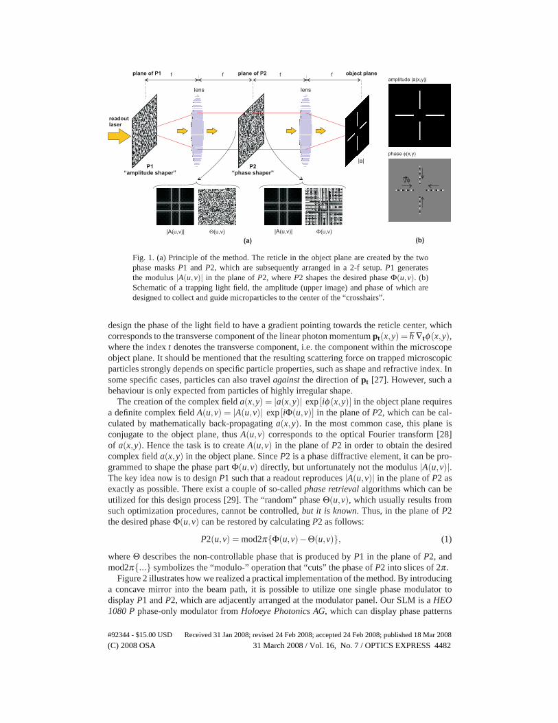
Figure 1(a) outlines the principle of the technique. Amplitude and phase of the light field areshaped in two subsequent steps by two phase diffractive elements (P1 and P2). Both elementsare arranged in a 2-f setup, i.e., they are placed in the front and back focal plane of a convexlens. Consequently, the Fourier Transform of the field in the plane of P1 emerges in the planeof P2. The principle of the method is explained in the following practical example.
Let us consider that we want to create a light field a(x,y) = |a(x,y)| exp [iφ(x,y)] in the objectplane, which collects particles like a funnel, i.e. which “grasps” and guides them towards a spe-cific point in the object plane. Such a light field represents the “reticle” shown in Fig. 1(b). Thefour bright lines confine particles by gradient forces. To maintain the “collecting” property, we
(C) 2008 OSA 31 March 2008 / Vol. 16, No. 7 / OPTICS EXPRESS 4481#92344 - $15.00 USD Received 31 Jan 2008; revised 24 Feb 2008; accepted 24 Feb 2008; published 18 Mar 2008
phase (x,y)�
amplitude |a(x,y)|
(b)
��
lens
f
P1“amplitude shaper”
f f fplane of P1 plane of P2 object plane
P2“phase shaper”
|A(u,v)| �(u,v) �(u,v)
lens
|a|
(a)
|A(u,v)|
readoutlaser
Fig. 1. (a) Principle of the method. The reticle in the object plane are created by the twophase masks P1 and P2, which are subsequently arranged in a 2-f setup. P1 generatesthe modulus |A(u,v)| in the plane of P2, where P2 shapes the desired phase Φ(u,v). (b)Schematic of a trapping light field, the amplitude (upper image) and phase of which aredesigned to collect and guide microparticles to the center of the “crosshairs”.
design the phase of the light field to have a gradient pointing towards the reticle center, whichcorresponds to the transverse component of the linear photon momentum pt(x,y) = h ∇tφ(x,y),where the index t denotes the transverse component, i.e. the component within the microscopeobject plane. It should be mentioned that the resulting scattering force on trapped microscopicparticles strongly depends on specific particle properties, such as shape and refractive index. Insome specific cases, particles can also travel against the direction of pt [27]. However, such abehaviour is only expected from particles of highly irregular shape.
The creation of the complex field a(x,y) = |a(x,y)| exp [iφ(x,y)] in the object plane requiresa definite complex field A(u,v) = |A(u,v)| exp [iΦ(u,v)] in the plane of P2, which can be cal-culated by mathematically back-propagating a(x,y). In the most common case, this plane isconjugate to the object plane, thus A(u,v) corresponds to the optical Fourier transform [28]of a(x,y). Hence the task is to create A(u,v) in the plane of P2 in order to obtain the desiredcomplex field a(x,y) in the object plane. Since P2 is a phase diffractive element, it can be pro-grammed to shape the phase part Φ(u,v) directly, but unfortunately not the modulus |A(u,v)|.The key idea now is to design P1 such that a readout reproduces |A(u,v)| in the plane of P2 asexactly as possible. There exist a couple of so-called phase retrieval algorithms which can beutilized for this design process [29]. The “random” phase Θ(u,v), which usually results fromsuch optimization procedures, cannot be controlled, but it is known. Thus, in the plane of P2the desired phase Φ(u,v) can be restored by calculating P2 as follows:
P2(u,v) = mod2π{Φ(u,v)−Θ(u,v)}, (1)
where Θ describes the non-controllable phase that is produced by P1 in the plane of P2, andmod2π{...} symbolizes the “modulo-” operation that “cuts” the phase of P2 into slices of 2π .
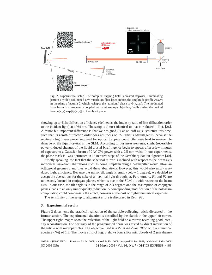
Figure 2 illustrates how we realized a practical implementation of the method. By introducinga concave mirror into the beam path, it is possible to utilize one single phase modulator todisplay P1 and P2, which are adjacently arranged at the modulator panel. Our SLM is a HEO1080 P phase-only modulator from Holoeye Photonics AG, which can display phase patterns
(C) 2008 OSA 31 March 2008 / Vol. 16, No. 7 / OPTICS EXPRESS 4482#92344 - $15.00 USD Received 31 Jan 2008; revised 24 Feb 2008; accepted 24 Feb 2008; published 18 Mar 2008
P2“phase shaper”
sphericalmirrorf =300 mmM
collimated beam@1064nm
PAL-SLM objective
dichroicmirror
to camera
f1=750 mm f2=400 mm
P1“amplitude shaper”
experiment:reticle focussed on mirror
5 µm
300 mm
Fig. 2. Experimental setup. The complex trapping field is created stepwise: Illuminatingpattern 1 with a collimated CW Ytterbium fiber laser creates the amplitude profile A(u,v)in the plane of pattern 2, which reshapes the “random” phase to Φ(kx,ky). The modulatedlaser beam is subsequently coupled into a microscope objective, finally taking the desiredform a(x,y) exp [iφ(x,y)] in the object plane.
showing up to 41% diffraction efficiency (defined as the intensity ratio of first diffraction orderto the incident light) at 1064 nm. The setup is almost identical to that introduced in Ref. [26].A minor but important difference is that we designed P1 as an “off-axis” structure this time,such that its zeroth diffraction order does not focus on P2. This is advantageous, because therelatively high laser power required for optical trapping could otherwise lead to irreversibledamage of the liquid crystal in the SLM. According to our measurements, slight (reversible)power-induced changes of the liquid crystal birefringence begin to appear after a few minutesof exposure to a Gaussian beam of 2 W CW power with a 2.5 mm waist. In our experiments,the phase mask P1 was optimized in 15 iterative steps of the Gerchberg-Saxton algorithm [30].
Strictly speaking, the fact that the spherical mirror is inclined with respect to the beam axisintroduces wavefront aberrations such as coma. Implementing a beamspitter would allow anorthogonal geometry and thus avoid these aberrations. However, this would also imply a re-duced light efficiency. Because the mirror tilt angle is small (below 1 degree), we decided toaccept the aberrations for the sake of a maximal light throughput. Furthermore, P1 and P2 arenot exactly located in conjugate planes, which is due to the SLM tilt with respect to the beamaxis. In our case, the tilt angle is in the range of 2-3 degrees and the assumption of conjugateplanes leads to an only minor quality reduction. A corresponding modification of the hologramcomputation could compensate the effect, however at the cost of higher numerical expenses.
The sensitivity of the setup to alignment errors is discussed in Ref. [26].
3. Experimental results
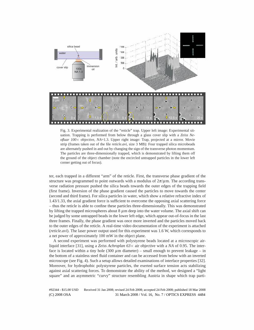
Figure 3 documents the practical realization of the particle-collecting reticle discussed in theformer section. The experimental situation is described by the sketch in the upper left corner.The upper right images show the reflection of the light field on a mirror, revealing good inten-sity reconstruction. The accuracy of the programmed phase was tested by direct interaction ofthe reticle with microparticles. The objective used is a Zeiss Neofluar 100× with a numericalaperture (NA) of 1.3. The movie strip of Fig. 3 shows four silica microbeads of 2 μm diame-
(C) 2008 OSA 31 March 2008 / Vol. 16, No. 7 / OPTICS EXPRESS 4483#92344 - $15.00 USD Received 31 Jan 2008; revised 24 Feb 2008; accepted 24 Feb 2008; published 18 Mar 2008
Int.
/arb
.units
0 s 1.5 s 5 s 11 s 12.5 s 20 s
5 µm
100xNA 1.3
silica bead
water
cover slip immersionoil
Fig. 3. Experimental realization of the “reticle” trap. Upper left image: Experimental sit-uation. Trapping is performed from below through a glass cover slip with a Zeiss Ne-ofluar 100× objective, NA=1.3. Upper right image: Trap, projected at a mirror. Moviestrip (frames taken out of the file reticle.avi, size 3 MB): Four trapped silica microbeadsare alternately pushed in and out by changing the sign of the transverse photon momentum.The particles are three-dimensionally trapped, which is demonstrated by lifting them offthe ground of the object chamber (note the encircled untrapped particles in the lower leftcorner getting out of focus).
ter, each trapped in a different “arm” of the reticle. First, the transverse phase gradient of thestructure was programmed to point outwards with a modulus of 2π/μm. The according trans-verse radiation pressure pushed the silica beads towards the outer edges of the trapping field(first frame). Inversion of the phase gradient caused the particles to move towards the center(second and third frame). For silica particles in water, which show a relative refractive index of1.43/1.33, the axial gradient force is sufficient to overcome the opposing axial scattering force– thus the reticle is able to confine these particles three-dimensionally. This was demonstratedby lifting the trapped microspheres about 8 μm deep into the water volume. The axial shift canbe judged by some untrapped beads in the lower left edge, which appear out-of-focus in the lastthree frames. Finally, the phase gradient was once more inverted and the particles moved backto the outer edges of the reticle. A real-time video documentation of the experiment is attached(reticle.avi). The laser power output used for this experiment was 1.6 W, which corresponds toa net power of approximately 100 mW in the object plane.
A second experiment was performed with polystyrene beads located at a microscopic air-liquid interface [31], using a Zeiss Achroplan 63× air objective with a NA of 0.95. The inter-face is located within a tiny hole (300 μm diameter) – small enough to prevent leakage – inthe bottom of a stainless steel fluid container and can be accessed from below with an invertedmicroscope (see Fig. 4). Such a setup allows detailed examinations of interface properties [32].Moreover, for hydrophobic polystyrene particles, the exerted surface tension acts stabilizingagainst axial scattering forces. To demonstrate the ability of the method, we designed a “lightsquare” and an asymmetric “curvy” structure resembling Austria in shape which trap parti-
(C) 2008 OSA 31 March 2008 / Vol. 16, No. 7 / OPTICS EXPRESS 4484#92344 - $15.00 USD Received 31 Jan 2008; revised 24 Feb 2008; accepted 24 Feb 2008; published 18 Mar 2008
Fig. 4. Upper left image: Trapping is performed at an air-liquid interface, which axiallystabilizes the hydrophobic microparticles (polystyrene beads, 3 μm diameter). Upper rightimage:“Square trap”. The microscopic light square traps particles and moves them alongits boundaries. The corresponding movie strip shows it “in action” (movie file square.avi,size 2.8 MB). The guiding performance of a asymmetric structure is demonstrated by thelower movie strip (movie file austria.avi, size 3.1 MB).
cles (about 3 μm in diameter) and push them along their boundaries by scattering forces. Thecorresponding transverse phase gradient has a modulus of 3.6×2π/μm. Again, the intensityreconstructions are almost speckle-free. The movie strips in Fig. 4 indicate that – in the caseof the square trap – the obtained particle speed (mean value 20 μm/s) is much higher than thatof the silica spheres in Fig. 3, although the programmed phase gradient is smaller. This is –besides the lower infrared absorption of the used air objective – mainly explained by the highernumber of beads (more beads gain more light momentum) and the higher refractive index ofthe particles (1.59 for polystyrene beads), which implies a higher scattering force. Because thisalso holds in axial direction, the gradient force by itself is now no longer sufficient to confinethe particles stably in the object plane. Hence for such particles another stabilizing force isrequired, which in our case is the surface tension. The laser power output used for the experi-ments with polystyrene beads was 1.4 W, which corresponds to a net power of approximately150 mW in the object plane.
(C) 2008 OSA 31 March 2008 / Vol. 16, No. 7 / OPTICS EXPRESS 4485#92344 - $15.00 USD Received 31 Jan 2008; revised 24 Feb 2008; accepted 24 Feb 2008; published 18 Mar 2008
Recently we have examined the applicability of a method for generating complex wavefrontsto liquid crystal SLMs. Here we demonstrate the usefulness of this technique for the opti-cal manipulation of microscopic dielectric particles that can be trapped by pre-defined optical“trapping patterns”. Similar to the method introduced in Refs. [17, 23], the method permitsindependent control over amplitude and phase of a light field, but with potentially higher effi-ciency. The technique makes use of two independent diffractive elements located in two distinctoptical planes: an “amplitude shaper” phase hologram in an image plane and a “phase shaper”hologram in a Fourier plane, thus the commonly used “Fourier manipulation techniques” (e.g.gratings and lenses for three-dimensional trap shifting) are extended by possibilities to alter thetrapping field via the element in the image plane (P1). For instance, lateral shifts of the trappingfield can be directly achieved by a corresponding motion of P1, which enables real-time steer-ing similar to that obtainable with a “Fresnel” setup [9]. We implemented the method using asingle user-programmable phase-only liquid crystal SLM.
Several alternative approaches for creating complex light fields with single phase masks havebeen suggested in the past [16, 17, 18]. Furthermore, phase retrieval techniques can be alsoemployed to reconstruct a complex amplitude field directly [33], however only in a restrictedarea and with unavoidable light losses.
Theoretically, the method described here would enable the generation of arbitrary light fieldswith almost 100% intensity efficiency. In our specific case, the maximal obtainable efficiencyis about 17%, which is mainly caused by the relatively high absorption by our SLM.
However, this technical restriction will be less severe in future generations of light modula-tors. In fact, even current systems claim to have light efficiencies of up to 80%, which wouldenable the presented “complex” holographic optical tweezers to reach up to 64% efficiency.
The method is well suited to create high contrast amplitudes in the plane of P2, which isespecially advantageous in the case of P2 being located in the Fourier plane, where field ampli-tudes often have a large dynamic range. However, high intensities may destroy the liquid crystal– hence, in some cases, P2 should rather be placed in a Fresnel than in the Fourier plane, wherethe amplitude contrast is typically smaller.
The presented “complex” holographic tweezers might be useful in different tasks concerningoptical trapping and manipulating microscopic particles or atoms, since its shows higher flexi-bility than commonly used techniques, which typically only allow controlling the amplitude oflight fields. For instance, one could use specifically tailored phase landscapes for transporting,sorting or controlled aggregation of microparticles.
Acknowledgments
This work was supported by the Austrian Science Foundation (FWF), Project No. P18051-N02and Project No. P19582.
(C) 2008 OSA 31 March 2008 / Vol. 16, No. 7 / OPTICS EXPRESS 4486#92344 - $15.00 USD Received 31 Jan 2008; revised 24 Feb 2008; accepted 24 Feb 2008; published 18 Mar 2008