Page 1
Name of the Student : Abhijit MirajkarStudent Registration No : BYB0911018
Module Leader at MSRSAS : Prof .Ashok C.Meti________________
POST
GR
AD
UA
TE E
NG
INE
ERIN
G A
ND
MA
NA
GE
MEN
T P
RO
GR
AM
ME
(PE
MP)
M.S.Ramaiah School of Advanced StudiesNew BEL Road, Gnanagangothri Campus, MSR Nagar, Bangalore-560 054
Tel/Fax: 23605539/23601983; website: http://www.msrsas.org
Centre Name: Automotive Engineering CentreCourse Name: M.Sc (Engg) in Automotive Engineering
FULL TIME 2011_ BATCH
ASSIGNMENT
Page 2
M.S Ramaiah School of Advanced Studies –Postgraduate Engineering and Management Programme (PEMP)
Modern Automotive Systemii
Declaration SheetDelegate’s Name Abhijit Mirajkar
Reg No BYB0911018Course M.Sc.[ENGG] in APD Batch 2011
Module Code AEL 501Module Title Modern Automative SystemModule Start Date 10-10-2011 Submission Date 05-11-2011Module Leader Prof.Ashok C.MetiSubmission ArrangementsThis assignment must be submitted to Academic Records Office (ARO) by the submission date before 1730 hoursfor both Full-Time and Part-Time students.
Extension requestsExtensions can only be granted by the Head of the Department / Course Manager. Extensions granted by any otherperson will not be accepted and hence the assignment will incur a penalty. A copy of the extension approval must beattached to the assignment submitted.
Late submission PenaltiesUnless you have submitted proof of Mitigating Circumstances or have been granted an extension, the penalties for alate submission of an assignment shall be as follows: Up to one week late: Penalty of one grade (5 marks) One-Two weeks late: Penalty of two grades (10 marks) More than Two weeks late: Fail - 0% recorded (F2)All late assignments must be submitted to Academic Records Office (ARO). It is your responsibility to ensure thatthe receipt of a late assignment is recorded in the ARO. If an extension was agreed, the authorization should besubmitted to ARO during the submission of assignment.
To ensure assignments are written concisely, the length should be restricted a limit indicated in the assignmentquestions. Each participant is required to retain a copy of the assignment in his or her record in case of any loss.
DeclarationThe assignment submitted herewith is a result of my own investigations and that I have conformed to the guidelines
against plagiarism as laid out in the PEMP Student Handbook. All sections of the text and results, which have been
obtained from other sources, are fully referenced. I understand that cheating and plagiarism constitute a breach of
University regulations and will be dealt with accordingly.
Signature of theDelegate Date
Date stamp fromARO
Signature ofARO Staff
Signature ofModule Leader
Signature ofCourse Manager
Page 3
M.S Ramaiah School of Advanced Studies –Postgraduate Engineering and Management Programme (PEMP)
Modern Automotive Systemiii
Attendance Details Theory Laboratory Fine Paid(if any for shortage of attendance)
Remarks
Assignment – Marks-Sheet (Assessor to Fill)
Part a b c d e f Total Remarks
A
B
C
Marks Scored for 100 Marks Scored out of 50Result PASS FAIL
Written Examination – Marks – Sheet (Assessor to Fill)
Q. No a b c d Total Remarks123456
Marks Scored for 100 Marks Scored out of 50Result PASS FAIL
PMAR- form completed for student feedback (Assessor has to mark) Yes NoOverall Result
Components Assessor ReviewerAssignment (Max 50) Pass Fail
Written Examination (Max 50) Pass Fail
Total Marks (Max 100) (Before Late Penalty) Grade
Total Marks (Max 100) (After Late Penalty) GradeA+ A A- B+ B B- C+ C FAIL
F2100-75 74-70 69-65 64-60 59-55 54-50 49-45 44-40 Less than 4034-2524-0IMPORTANT
1. The assignment and examination marks have to be rounded off to the nearest integer and entered in the respective fields2. A minimum of 40% required for a pass in both assignment and written test individually3. A student cannot fail on application of late penalty (i.e. on application of late penalty if the marks are below 40, cap at 40 marks)
Signature of Reviewer with date Signature of Module Leader with date
M. S. Ramaiah School of Advanced StudiesPostgraduate Engineering and Management Programme- Coventry University (UK)
Assessment Sheet
Department Automotive and Aeronautical EngineeringCourse M.Sc in Automotive Product Design Batch Full-Time 2011Module Code AEL 501 Module Title Modern Automotive Systems
Module Leader Proff. Ashock.C.Meti Module CompletionDate 05th Nov 2011
Student Name Abhijit.Mirajkar ID Number BYB0911018
Page 4
M.S Ramaiah School of Advanced Studies –Postgraduate Engineering and Management Programme (PEMP)
Modern Automotive Systemiv
Abstract_______________________________________________________________________
In this module we learnt about modern automotive system technology. Electronics
combined with mechanics have made the drastic change to the automotive world. The safety and
comfort level is also improved by implementing advance technology. The different types of
modern gearboxes used in vehicle and their performance are been explained in Part A.
Brake system is most important safety system that is very basic essential in every
vehicle. Implementing new technology like ABS the care is taken to provide more safety and the
accident rate has been reduced. The basic principle, working of conventional braking system,
hydraulic circuits and the limitation has been explained in Part B.
Braking system controlled by electronics reduces the cost, space and manufacturing time.
ABS controller by electronic provide greater safety. All the vehicles are coming in market with
Electronic braking system. So in Part C different types of components, their individual working
and a case study of a particular vehicle have been explained.
Page 5
M.S Ramaiah School of Advanced Studies –Postgraduate Engineering and Management Programme (PEMP)
Modern Automotive Systemv
Table of contents_______________________________________________________________________
Abstract.........................................................................................................................................iv
Table of contents ...........................................................................................................................v
List of Figures............................................................................................................................. vii
List of tables............................................................................................................................... viii
Nomenclature ...............................................................................................................................ix
CHAPTER 1 ..................................................................................................................................1
1.1 A brief introduction to modern gear box and their role in vehicle performances.....1
1.2 Technologies that drive the gearbox configurations and control systems. ...............1
1.3 Automotive transmissions-present and emerging trends – your views on this.........3
Conclusion: ....................................................................................................................................3
CHAPTER 2 ..................................................................................................................................4
2.1 Braking system..........................................................................................................4
2.1.1 Mechanical brakes .............................................................................................4
2.1.2 Hydraulic brakes ................................................................................................5
2.1.3 Air brakes...........................................................................................................5
2.1.4 There are two types of wheel brake systems .....................................................5
2.1.5 Regulatory..........................................................................................................7
2.2 Brief discussion with schematic layout of conventional hydraulic braking system
used in a car. ...................................................................................................................8
2.2.1 Working .............................................................................................................8
2.2.2 Different types of schematic lay out: .................................................................9
2.3 Identification and discussions on the limitations of the conventional brake systems
with the focus on the background theory. .....................................................................11
2.3.1 Mechanical limitations.....................................................................................11
2.3.2 Wheel lockup ...................................................................................................12
2.3.3 Steering wheel lockup......................................................................................12
2.3.4 Noise ................................................................................................................12
2.3.5 Tires wear out ..................................................................................................12
2.3.6 Brake bleeding .................................................................................................12
Page 6
M.S Ramaiah School of Advanced Studies –Postgraduate Engineering and Management Programme (PEMP)
Modern Automotive Systemvi
2.4 Critical analysis of new development or technologies to overcome the limitations
of the conventional braking systems.............................................................................13
2.4.1 Anti Lock Braking System (ABS) ...................................................................13
2.4.2 Traction control system (TCS).........................................................................14
2.4.3 Electronic stability program (ESP) ..................................................................14
CHAPTER 3 ................................................................................................................................16
3.1 Brief introduction and discussion on suggested individual components with
details such as purpose, construction and working.......................................................16
3.1.1System components of ABS .............................................................................17
3.2 Suggested configuration of a typical system integrated with all the components and
explanation....................................................................................................................21
3.2.1 Two position solenoid......................................................................................23
3.3 Discussion on control logic used in the working of complete system with relevant
diagrams and graph. ......................................................................................................24
3.3.1 Anti-lock braking system using fuzzy logic work as follows:.........................25
3.4 Key features of implementation on any vehicle case study. ...................................26
3.4.1 Mercedes Sensotronic Brakes ..........................................................................26
3.4.2 Benefits of using Sensotronic braking control.................................................28
3.5 You are also required to comment on the benefits got through solving this
assignments and whether assignment was able to access module learning outcomes or
not? …………………………………………………………………………………30
BIBILOGRAPHY .......................................................................................................................31
Page 7
M.S Ramaiah School of Advanced Studies –Postgraduate Engineering and Management Programme (PEMP)
Modern Automotive Systemvii
List of Figures_______________________________________________________________________Figure: 2. 1.Automotive braking system [4].......................................................................4
Figure: 2. 2 Brakes free condition [5].................................................................................5
Figure: 2. 3 Brake applied condition [5] .............................................................................5
Figure: 2. 4 Diagram of disc brake components [6] ...........................................................6
Figure: 2. 5 Basic automotive hydraulic brake system [15] ...............................................8
Figure: 2. 6 Weight transfer [14] ........................................................................................8
Figure: 2. 7 l l distribution pattern [3].................................................................................9
Figure: 2. 8 X distribution pattern [3] .................................................................................9
Figure: 2. 9 H I Distribution pattern [3]............................................................................10
Figure: 2. 10 LL Distribution pattern [3] ..........................................................................10
Figure: 2. 11 HH Distribution pattern [3] .........................................................................10
Figure: 2. 12 Wheel locking diagram [11]........................................................................12
Figure: 2. 13 Non-ABS braking system [1] ......................................................................13
Figure: 2. 14 ABS braking system [1] ..............................................................................13
Figure: 2. 15 Different traction surface to each wheel [12] ..............................................14
Figure: 2. 16 Vehicle experiencing over steering and under steering [13] .......................14
Figure: 3. 1 ABS Diagram [2]...........................................................................................16
Figure: 3. 2 Front and rear wheel sensors [2] ...................................................................17
Figure: 3. 3 Working diagram of speed sensor [2] ...........................................................18
Figure: 3. 4 Working diagram to deceleration sensor [2] .................................................19
Figure: 3. 5 Diagram of ABS Actuator [2] .......................................................................19
Figure: 3. 6 ECU Diagram [10] ........................................................................................20
Figure: 3. 7 Circuit diagram of ABS relay control [2]......................................................20
Figure: 3. 8 Layout of ABS system [2].............................................................................21
Figure: 3. 9 ABS graph with slip ratio under different traction [2] ..................................22
Figure: 3. 10 Two-position solenoids hydraulic circuits [2].............................................23
Figure: 3. 11 Graph of variable temperature [9] ...............................................................24
Figure: 3. 12 Fuzzy logic controlled model for ABS [8] ..................................................25
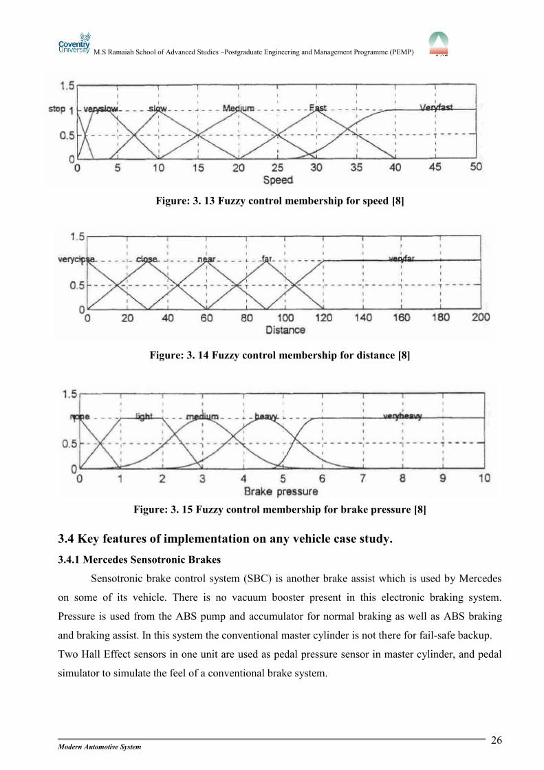
Figure: 3. 13 Fuzzy control membership for speed [8].....................................................26
Figure: 3. 14 Fuzzy control membership for distance [8].................................................26
Figure: 3. 15 Fuzzy control membership for brake pressure [8].......................................26
Figure: 3. 16 Sensotronic brake control setup [7].............................................................27
Page 8
M.S Ramaiah School of Advanced Studies –Postgraduate Engineering and Management Programme (PEMP)
Modern Automotive Systemviii
List of tablesNo tables of figure entry found.
Page 9
M.S Ramaiah School of Advanced Studies –Postgraduate Engineering and Management Programme (PEMP)
Modern Automotive Systemix
NomenclatureAcronyms
ABS: Anti-lock braking system
TCU: Traction control unit
ESP: Electronic stability program
SBC: Sensotronic braking control
ECU: Electronic control unit
ACC: Adaptive cruise control
HCU: Hydraulic control unit
LTC: Lock up torque converter
DCT: Dual clutch transmission
CVT: Continuously variable transmission
IVT: Infinitely variable transmission
TCM: Transmission control module
FMVSS: Federal motor vehicle safety standards
DSC: Dynamic stability control
PSM: Porsche stability management
ETC: Electronic traction control
Page 10
M.S Ramaiah School of Advanced Studies –Postgraduate Engineering and Management Programme (PEMP)
Modern Automotive System
CHAPTER 1______________________________________________________________________________
1.1 A brief introduction to modern gear box and their role in vehicle
performances.Automotive industry is one of the fast and vast growing industries. As the growth of this
industry is higher the challenges are also bigger to provide safety and comfort level. Transmission
plays important role in automobiles. Transmission has been continuously developing to get the best
and advanced from the past, Torque produced by IC engines is less in low speed, and with this
torque available, Traction force required is not sufficient to move vehicle from the rest position so to
get the higher traction force gear box has been introduced. With the help of gears speed range can be
varied and also the engine main shaft rotate in one direction the reverse motion is not possible
without gears.
There are many different types of transmission. Manual transmission, in this system gears are
shifted with the help lever and clutch operated manually here synchronizer unit meshes gears in up
and down shifts. Automatic transmission, here the gear shifting take place automatically with the
help of TCU, clutches are replaced by torque converter and by using Simpson, Ravingeaux
compound planetary gear sets. Semi automatic transmission, Next step they introduced CVT
continuously variable transmission here gears were eliminated, and the transmission was by variable
pulley and endless belt and even further IVT infinite variable transmissions came into existence.
Dual Clutch Transmission is one of the latest transmissions, where the system has two clutches
where different gears are mounted on each clutch.
Modern gear box role in vehicle performance are as follows:
Fuel consumption is less as TCU chooses gears at different road conditions.
Modern transmission provides a good comfort as the gears are automatically shifted;
Traction jerks are not experienced while driving.
Drivability is effective even when an unskilled driver is riding the vehicle.
Space required to install modern transmission is huge, by using TCU the space utilization can
be reduced.
Cost of production can be reduced using simple systems which can perform multi operations.
1.2 Technologies that drive the gearbox configurations and control systems.In manual transmission the gear boxes are driven by clutch assembly. Clutch is located
between engine fly wheel and transmission. Clutch is a mechanism for transmitting rotation. Clutch
Page 11
M.S Ramaiah School of Advanced Studies –Postgraduate Engineering and Management Programme (PEMP)
Modern Automotive System2
assembly contains Clutch disc, Pressure plate assembly, Release bearing and hub, Clutch linkage,
Clutch fork, Clutch housing.
In automatic transmission clutches are replaced by torque converter. Torque converter is used
to transfer the torque generated by engine to the transmission. Torque converter is also known as
fluid clutch. It is located between the engine fly wheel and the transmission. The torque converter is
used to multiply the torque when there is difference between input and output rotational speed. The
fluid used to provide hydraulic force in torque converter is called transmission oil. In this technology
as per the engine RPM the power is engaged and disengaged automatically. Overrunning clutch is a
technology in which the stator assembly rotates in one direction when driven and allows rotation
when turned in other direction. Roller type overrunning clutch are used in rotating stator that permits
the stator to rotate independent when the speed of the turbine and impeller reach the coupling point.
Overrunning clutch consists of Movable inner race, Rollers, Accordion spring and Outer race.
Lockup torque converters are introduced to eliminate slip which occurs in between impeller and the
turbine at the coupling stage, by using this technology 10% of slip can be eliminated. LTC improves
fuel economy and reduces heat generated while operation, engine speed. LTC effectively changes
the converter into mechanical coupling. Dual clutch transmission is a type of semi automatic
transmission. Dual clutch has two separate clutches for odd and even series of gear sets. It is housing
were two separate manual transmission work as a unit. It allows driver to shift gears manually and it
is operated in fully automatic mode. Torque converter is eliminated in dual clutch transmissions;
instead of torque converter two oil-bathed wet multi-plate clutches are used.
Transmission control unit (TCU) is electronic controlled transmission used to precise shift
control, Lockup control, Engine torque control and safety functions with the help of engine
electronics. Engine RPM information is received by TCM, throttle position and load is provided to
the best shift points to maximize fuel efficiency and driver comfort. TCU increases driving safety by
driver less interaction. Provides improved shift comfort by use of over shift technology and also
provides more features using the CAN bus technology. Information inputs given to computers are by
two sources one direct from a sensor and through the CAN communication bus which is connect
with the vehicles computer systems. TCM receives bus inputs from Throttle position sensor, Mass
air flow sensor, manifold absolute pressure sensor, Intake air temperature sensor, Engine coolant
temperature sensor, Barometric pressure sensor and crankshaft position sensors. Outputs are by
indicators lamp and solenoids. Selected gear is indicated in instrumental panel by indicator lamp.
With the help of shift solenoid shift timing and feel is controlled. Pressure control solenoids are
mainly used to precise pressure control during shifts with the help of electronic. High pressure
Page 12
M.S Ramaiah School of Advanced Studies –Postgraduate Engineering and Management Programme (PEMP)
Modern Automotive System3
results in rough shifting and low pressure causes clutch to overheat. Torque converter clutch
solenoids are controlled by electronically. It monitors the lock up and release of TCC.
1.3 Automotive transmissions-present and emerging trends – your views on this.A transmission depends upon different road condition and customer demands. The present
trend transmission has different kinds of transmission systems used for the automobiles. They are
Manual transmission, automatic transmission, continuously variable transmission and semi
automatic transmission. Emerging trend is of semi-automatic transmission, which is a very advanced
system, where the gears do not change automatically; still uses a clutch pedal at the same time when
the gear shifts. Different from the manual transmission, computer controls the clutch disengaging,
gear shifting, and the clutch engaging. It improves the gear changing comfort and make faster than
manual transmission and also prevents stalling when the car is stationary (Tiptronic transmission). In
this developing world of technology there are people who loves to thrill with high performance cars
by cleverly shifting manual transmission and also people with not much worried about the car
performance but looks at the driving comforts for such peoples shifters are been introduced. But the
people who are familiar with shifter in auto transmission vehicle finds difficult to ride vehicle with
manual transmission so to avoid such discomfort automotive industry has come up with the
different types of modes in transmission, where the driver is offered with the options to choose the
suitable modes as per the road condition. Upcoming models have these special features they are
Manual mode, Sport mode, Paddle shifters. But as the comfort options increases the value of the
vehicle also goes high. In future trend CVT will gradually replace the conventional automatic
transmission because of its high fuel efficiency and in semi automatic transmission system the
technology will be improved to perform smooth gear shift and extend the car life without losing fuel
economy and fast acceleration.
Conclusion:‘Manual transmissions-are they on the verge of extinct?’Stand taken: NO
Automotive industries are developing day by day as the demand for vehicles are increased.
Development is on the bases of the past. They are not completely changing the technologies, but
improving the features of systems which are in existence. Manual transmission will not completely
eliminate, as the new technology of transmission are expensive the vehicles cost will be higher.
People with high income can afford, but out of budget to the middle class peoples. The challenge to
automotive industry is to provide the new technology system to the cost of the old. So manual
transmission system will be combined with other system but will not come to end.
Page 13
M.S Ramaiah School of Advanced Studies –Postgraduate Engineering and Management Programme (PEMP)
Modern Automotive System4
CHAPTER 2______________________________________________________________________________
2.1 Braking systemBraking systems are essentially required in automobile, with safety being the most important.
The braking systems have to work in all critical conditions safely. Safety and reliability are
subjected to adjustment of speed and distance with response to the traffic conditions, these factors
lead to invent braking systems. Brakes are used to slow or stop the vehicle when the friction of the
tire is against the road. The momentum of the vehicle is converted to heat energy by slowing and
stopping of vehicle wheel through braking system generating friction at the wheels. The three factors
of generating friction are Pressure, Coefficient of friction and frictional contact surface.
Figure: 2. 1.Automotive braking system [4]
There are three types of brakes used in automotives
1. Mechanical brakes
2. Hydraulic brakes
3. Air brakes
2.1.1 Mechanical brakes
Mechanical brakes are used in parking brakes (hand brakes). Mechanical brakes are located
at the rear wheels which are connected with a steel wire and the other end is connected to the lever
near the driver’s seat. When hand brakes are engaged, tension is developed at the brakes and the
brake shoes restrict the drum from rotation, restricting the vehicles movement.
Page 14
M.S Ramaiah School of Advanced Studies –Postgraduate Engineering and Management Programme (PEMP)
Modern Automotive System5
2.1.2 Hydraulic brakes
When brake pedal is applied by a driver with some pressure, the mechanical force is
converted to hydraulic pressure which is transmitted through liquid to wheel cylinder and is changed
to mechanical force again, by operation on brake pads and brake shoes.
2.1.3 Air brakes
Air brakes have the same working as of hydraulic brakes. Here the mechanical force is
transmitted to the wheel by air pressure, instead of hydraulic pressure. This brake system is most
preferred in heavy vehicles.
2.1.4 There are two types of wheel brake systems
2.1.4.1 Drum brakes
Drum brakes assembly has a cast-iron drum, which is bolted to the vehicle wheels such that
the drum also rotates when the wheel is rotated and consists of a fixed backing plate to which the
shoes, wheel cylinders, automatic adjusters and linkages are attached and for parking brakes some
extra hardware’s are provided. Frictional linings are provided on the face of shoe which rubs the
inner surface of the drum when the brakes are applied to stop the vehicle. Movements of shoes are
controlled by small piston, which is located in wheel cylinder. So when the brakes are applied piston
forces the shoes against the drum which lead to convert kinetic energy in heat energy. Actuation of
the piston is by hydraulic pressure. Heat generated while braking is passed into atmosphere through
the ventilations provided. Pistons are retained back when the pedal is released by this hydraulic
pressure is dropped and with the help of return spring pistons are forced back.
Figure: 2. 2 Brakes free condition [5] Figure: 2. 3 Brake applied condition [5]
Page 15
M.S Ramaiah School of Advanced Studies –Postgraduate Engineering and Management Programme (PEMP)
Modern Automotive System6
2.1.4.1.1 Brake shoes
Brake shoes is a steel shoes on which friction material are bonded or riveted, Frictionmaterial are also called lining . Lining are used to reduce the wear out between steel and linings alsoget worn out after some duration, lining must be replaced at regular interval to avoid damage of thebrake drum.2.1.4.1.2 Backing plate
Backing plate is also called as support plate, it holds everything together. Backing plate is
attached to the axle forming a complete unit for a wheel cylinder, brake shoes and various kinds of
hardware. Break down of backing plate very rare.
2.1.4.1.3 Brake drums
Brake drums are made up of iron and inner surface is machined with fine finish where the
brake shoes get contact. Brake drum has a maximum diameter specification that is marked on the
outside of the drum. Drum must be machined within the given measurement.
2.1.4.1.4 Wheel cylinder
The wheel cylinder consists of a cylinder that has two pistons, opposite to each other.
Individual piston has a rubber seal and a shaft which connects the piston with the brake shoes.
Pistons are forced out pushing brake shoes get in contact with the drum when the brake is applied.
2.1.4.1.5 Return springs
Return springs are used to retain the piston to the rest position when the brake pedal is
released. If the springs are weak, the retaining of the piston is not possible this leads to excess lining
wear out.
2.1.4.1.6 Self adjusting systems
Regular cleaning and maintain to be made of the parts of a self adjusting system. Its role is to
maintain the adjustment over the life of the brake linings.
2.1.4.2 Disk brake
Figure: 2. 4 Diagram of disc brake components [6]
Page 16
M.S Ramaiah School of Advanced Studies –Postgraduate Engineering and Management Programme (PEMP)
Modern Automotive System7
Disc brake is best brake system in present technologies; it is not only used in cars also in
locomotives and jumbo jets. Wears in disc brakes are longer, they are less affected by water, self
adjusting, self-cleaning. Disc brake assembly contains Rotor, Brake pads, Caliper and Caliper
support. In this system the rotor is squeezed by brake pads. Rotors are clamped to the rotating
wheel. Brake pads are attached to metal backings, which are actuated by pistons. Pistons are located
within the caliper assembly. Caliper assembly is housing around the edge of the rotor. Rotation can
be stopped by the steering knuckle with caliper mounted on it. Caliper consist bleeder screw,
springs, pistons and related seals, cylinders and fluid passage which pushes the pads against the
rotor.
2.1.4.2.1 Brake pads
Brake pads are constructed of a metal shoe with a lining riveted or bonded to it. There are
two brake pads which are mounted in a caliper. Brake linings are used on the metal shoe to avoid
excess wear. Brake linings are made up of asbestos because of its good heat absorbing properties.
2.1.4.2.2 Rotors
Rotors are made of cast iron and are machined with fine finish on both the sides. Wear is also
subjected in the rotor but not as much as in brake pads. The wear patterns on rotor as well as the
brake pads are same. The minimum thickness measurement is stamped on the rotor.
2.1.4.2.3 Caliper and support
Calipers are of two type single piston floating caliper and four piston fixed caliper. Single
piston caliper is the most popular and also cost of manufacturing and servicing is low. When the
pushes the brake pads against the rotor the caliper moves to centralize, so this mechanism is called
floating calipers. Four piston fixed caliper are very efficient and have a better feel, But are more very
expensive to manufacture and even servicing costs more. In this mechanism there are two pistons on
each and opposite side of rotors. Caliper is rigidly fixed to the support. Pistons moves and rubs
against the rotor when the brake is applied. Four piston fixed caliper is used in high performance
cars.
2.1.5 Regulatory
According to FMVSS: Federal motor vehicle safety standards and regulatory, from the
standard no 105. Regulatory requirements for braking systems in car as per FMVSS 105
defines services are:
Lightly load to fully load at gross vehicle weight rating.
Pre-burnish to full burnish conditions
Speeds from 30 to 100 mph
Page 17
M.S Ramaiah School of Advanced Studies –Postgraduate Engineering and Management Programme (PEMP)
Modern Automotive System8
Partially failed systems tests
Failure indicator systems
Water recovery
Fade and recovery
Brake control force limit
2.2 Brief discussion with schematic layout of conventional hydraulic braking
system used in a car.
Figure: 2. 5 Basic automotive hydraulic brake system [15]
2.2.1 Working
When the brakes are need to be operated, driver press the brake pedal, by moving the piston
rod which joins it to the piston of the brake booster. Force applied by the driver is amplified by
brake booster and transmits the amplified force to the push rod which is connected to the master
brake cylinder. Brake master cylinder is used to convert mechanical force into hydraulic pressure.
The two pistons of the brake master cylinder press brake fluid out of the pressure chambers into the
brake lines or brake hoses and in this way the hydraulic pressure is transferred to the wheel brakes of
front and rear axles. Vehicle is not dependent on single circuit if one circuit fails the other circuit
works guarantying brake system. Brake fluid reservoir is connected to the brake master cylinder to
compensate the volume fluctuations in the brake circuits.
Figure: 2. 6 Weight transfer [14]
Page 18
M.S Ramaiah School of Advanced Studies –Postgraduate Engineering and Management Programme (PEMP)
Modern Automotive System9
While decelerating, when the brakes are applied the large proportion of the vehicles weight is
shifted from the rear wheels to the front wheels. So the braking pressure at rear wheels is lowered by
braking force regulator or limiter preventing them from over braking. Parking brakes are operated by
the hand brake lever and hand brake cables. Parking brakes are located at the rear wheel.
Master cylinders: Pressure on the brake pedal is distributed to each of the wheel to stop the vehicles
by means of master cylinder. It converts driver mechanical force into hydraulic force, which is again
changed back to mechanical at the wheels. Master cylinder multiplies single forced applied by driver
into number of wheels.
2.2.2 Different types of schematic lay out:
Figure: 2. 7 l l distribution pattern [3]
Front-axle/rear-axle split. In this pattern one circuit brake front axle and the other circuit brake the
rear axle.
Figure: 2. 8 X distribution pattern [3]
Diagonal Distribution Pattern, in this pattern each circuit brakes a front wheel and the diagonally
opposite rear wheel.
Page 19
M.S Ramaiah School of Advanced Studies –Postgraduate Engineering and Management Programme (PEMP)
Modern Automotive System10
Figure: 2. 9 H I Distribution pattern [3]
Front-axle and rear-axle/front-axle split. In this pattern, one circuit brakes the front and rear axles
and one circuit brakes only the front axle.
Figure: 2. 10 LL Distribution pattern [3]
Front-axle and rear-axle wheel/front-axle and rear-wheel split, in this pattern each circuit operates
both front wheels and one rear wheel.
Figure: 2. 11 HH Distribution pattern [3]
Page 20
M.S Ramaiah School of Advanced Studies –Postgraduate Engineering and Management Programme (PEMP)
Modern Automotive System11
Front-axle and rear-axle/front-axle and rear-axle split, in this pattern each circuit operates all four
wheels.
2.3 Identification and discussions on the limitations of the conventional brake
systems with the focus on the background theory.
Limitations are as follow:
1. Mechanical limitations
2. Wheel lockup
3. Steering wheel lockup
4. Noise
5. Tire wear out
6. Brake bleeding2.3.1 Mechanical limitations
All mechanical parts suffer with wear and tear over time, as per reference the lifetime of the
vehicle is only eight years. There are some of the failures because of mechanical limitation.
1. Loss of brake efficiency
2. Brake binding
3. Brake over heating
4. Brake judder
5. Vehicle pulling to one side
6. Hand brakes ineffective
7. Excessive loss of brake fluid
8. Excessive air bubbles
2.3.1.4 Cause for above problems.
Loss of brake efficiency is caused because of oil soaked brake drum and liners, Worn-out
brake linings and Defect of master cylinder. Brake binding is caused by brake shoes retracting
springs weak and Defects in wheel cylinders. Brake overheating is caused because of long usage of
the brake. Brake judder is caused by wrong adjustment of brakes and loose of lining rivets. Vehicle
pulling on one side is caused by improper adjustments of linings and oil or grease settled on liners.
Hand brake ineffective is caused by stretching of operating cable. Excessive loss of brake fluid is
caused by leakages found in master cylinder or wheel cylinder or hose joints. Excessive air bubbles
are caused by defective master cylinder.
Page 21
M.S Ramaiah School of Advanced Studies –Postgraduate Engineering and Management Programme (PEMP)
Modern Automotive System12
2.3.2 Wheel lockup
Figure: 2. 12 Wheel locking diagram [11]
When the brake pressure is applied by the driver with some force the wheels are subjected to
lock after some distance, in conventional brake system the wheel comes to rest but the vehicle
movement is not stopped resulting skid of the vehicle. Here A is wheel locking distance, B is
slipping distance and C is the total distance to stop the vehicle.
2.3.3 Steering wheel lockup
When the brakes are applied to stop the vehicle after some distance wheel get lockup and the
vehicle weight is transferred to the front axle, such that front axle experiences more weight than the
rear axle. So it causes to steering wheel lockup and loss of control on steering wheel, when tends to
drag the vehicle in some other direction.
2.3.4 Noise
When the brake is applied the kinetic energy is converted into heat, even we can hear a
rubbing noise in braking contributing to noise pollution. Noise produced differs, with tire
construction, Road surface and in deceleration.
2.3.5 Tires wear out
When the vehicle is slipping wheels are subjected to rub against the road. It this condition
wheels are not worn equally throughout the radius, but only at some area. Uneven wear out of tires.
2.3.6 Brake bleeding
Gases can be compressed but fluids cannot be compressed. If any air is found in fluid brake
hydraulic system air get compressed as the pressure is increased. Because of this the force is reduced
that can be transmitted by the fluid. This is the important reason to keep bubbles out of the hydraulic
system. To keep air free from hydraulic system, air must be released from brakes. Airs bubbles are
formed because of continuous hydraulic pressure oil O rings get worn out which results in air
mixture.
Page 22
M.S Ramaiah School of Advanced Studies –Postgraduate Engineering and Management Programme (PEMP)
Modern Automotive System13
2.4 Critical analysis of new development or technologies to overcome the
limitations of the conventional braking systems.Mechanical limitations cannot be eliminated completely but regular servicing and minor
replacement can hold good to some extends. Following are the remedies for above identified
problem are:
Loss of brake efficiency can fixed by replacing wheel cylinder and liners, Brake binding
problem can be fixed by replacing brake shoe retracting spring and wheel cylinder, Brake judder can
be fixed by adjusting brake adjuster and by replacing loose lining rivets, Vehicle pulling to one side
problem can be fixed adjusting improper adjustment of linings and replacing oil or grease settled on
liners, Hand brake ineffective can be fixed by replacing operating cable, Excessive loss of brake
fluid can be fixed by servicing and replacing master cylinder or wheel cylinder or hose joints.
Excessive air bubbles this problem can be eliminated by replacing defective master cylinder.
2.4.1 Anti Lock Braking System (ABS)
Figure: 2. 13 Non-ABS braking system [1] Figure: 2. 14 ABS braking system [1]
Anti-lock braking system (ABS) is a safety system that allows wheels in vehicle to continue
interacting tractively with the road surface, preventing the wheels from locking up avoiding skidding
of vehicle. This system is control electronically. When driver applies the brake the mechanical
pressure is converted to a hydraulic system which causes the brake pads to rub against the disc and
slow down or stop the car. If one wheel is slowing first than the other wheels the pressure on this
wheel is automatically reduced and balances the same pressure on each wheels. Ability to build the
pressure back up via the hydraulic motor can be achieved by ABS.
Page 23
M.S Ramaiah School of Advanced Studies –Postgraduate Engineering and Management Programme (PEMP)
Modern Automotive System14
2.4.2 Traction control system (TCS)
Figure: 2. 15 Different traction surface to each wheel [12]
Traction control is mainly used to reduce drive loss through spinning wheels. This condition
occurs when driving the vehicle on slippery roads, or when we are accelerating hard on turning.
Traction control applies the brakes to spinning wheel and by wheel gets the best grip. Traction
control is operated below certain speed.
2.4.3 Electronic stability program (ESP)
Figure: 2. 16 Vehicle experiencing over steering and under steering [13]
Electronic stability control system helps in detecting the loss of traction to individual wheels
and reacts to regain the grip using brake system and engine management systems. Under steering,
Over steering and wheel spinning are the situation where this system will come into action.
Page 24
M.S Ramaiah School of Advanced Studies –Postgraduate Engineering and Management Programme (PEMP)
Modern Automotive System15
2.4.3.1 Different car manufacturers using this system on different names like:
Dynamic stability control (DSC)
Electronic stability program (ESP)
Porsche stability management (PSM)
Electronic traction control (ETC)
Page 25
M.S Ramaiah School of Advanced Studies –Postgraduate Engineering and Management Programme (PEMP)
Modern Automotive System16
CHAPTER 3______________________________________________________________________________
3.1Brief introduction and discussion on suggested individual components with
details such as purpose, construction and working
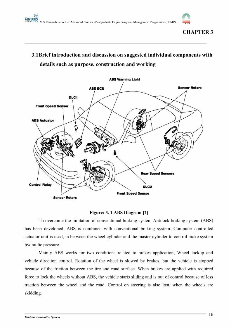
Figure: 3. 1 ABS Diagram [2]
To overcome the limitation of conventional braking system Antilock braking system (ABS)
has been developed. ABS is combined with conventional braking system. Computer controlled
actuator unit is used, in between the wheel cylinder and the master cylinder to control brake system
hydraulic pressure.
Mainly ABS works for two conditions related to brakes application, Wheel lockup and
vehicle direction control. Rotation of the wheel is slowed by brakes, but the vehicle is stopped
because of the friction between the tire and road surface. When brakes are applied with required
force to lock the wheels without ABS, the vehicle starts sliding and is out of control because of less
traction between the wheel and the road. Control on steering is also lost, when the wheels are
skidding.
Page 26
M.S Ramaiah School of Advanced Studies –Postgraduate Engineering and Management Programme (PEMP)
Modern Automotive System17
High level of safety is provided to the driver by preventing the wheels from locking by using
ABS is only possible. It also maintains directional stability. A professional driver may use his skill
to maintain control during braking by pumping the brake pedal which allows turn momentarily. But
the professional driver may skilled enough to pump the brake pedal once per second. ABS is capable
of deviating brake pressure fifteen times per seconds. One thing that cannot done by driver is done
by ABS, it controls each front brake separately and rear brakes as pair whenever the wheels start
locking ABS stops the vehicle in short distance without wheel locking up which maintain
directional control on the most type of road surface. If ABS system fails, vehicle can be stopped by
normal brakes.
3.1.1System components of ABS
Speed sensors
G-sensors
ABS actuators
Control relay
ABS ECU
ABS warning lamp
3.1.1.1 Wheel speed sensors
Figure: 3. 2 Front and rear wheel sensors [2]
Wheel speed sensor is mounted at each wheel and sends the rotation signal to the ABS ECU.
Both the front and rear wheel speed sensor has a permanent magnet which is attached to a soft iron
core and a wire wound coil. Front wheel speed sensor is mounted on the steering knuckle, and the
Page 27
M.S Ramaiah School of Advanced Studies –Postgraduate Engineering and Management Programme (PEMP)
Modern Automotive System18
rear wheel speed sensors are mounted to the rear axle carrier. To count the rotations serrated rotors
are mounted to the drive axle shaft or brake rotor.
Figure: 3. 3 Working diagram of speed sensor [2]
3.1.1.1.1 Working
Working of wheel speed sensor is similar to the magnetic pick-up distributor. When the teeth
of the sensors rotor passes through the iron core, the magnetic line of force cut through the coil
windings causing a voltage to be induced into the coil. As the tooth near the iron core, the magnetic
field contracts causing the positive voltage to be induced in the coil. When the tooth is centered on
the iron core, the magnetic field does not move and zero volts are induced in the coil. As the tooth
moves away from the iron core the magnetic field expands, which results in negative voltage. When
rotation of the rotor sensor increases, the voltage and frequency signal also increases. By inputting to
ECU, higher wheel speed.
3.1.1.2 Deceleration sensors
Deceleration sensor is used to provide input to the ABS ECU about the vehicle deceleration rate to
improve braking performance. In ABS system, ECU compares speed sensors to determine the speed
of the vehicle and rate of deceleration. Deceleration sensor is used on all four wheel drive vehicles
equipped with ABS to calculate deceleration.
Page 28
M.S Ramaiah School of Advanced Studies –Postgraduate Engineering and Management Programme (PEMP)
Modern Automotive System19
Figure: 3. 4 Working diagram to deceleration sensor [2]
3.1.1.2.1 Working of deceleration sensor:
Two LED’s are placed on one side of the split plate and two photo transistors are located on
the opposite side. When ignition switch is ON the LED’s also gets ON. When vehicle is
decelerating, the split plates act to expose the light from the LED’s to the photo transistors. The
Movement of splits switches the photo transistor on and off.
3.1.1.3 ABS Actuator
Figure: 3. 5 Diagram of ABS Actuator [2]
The actuator controls hydraulic brake pressure to each disc brake caliper or wheel cylinder
based on input from the system sensors, which controls wheel speed. These solenoids provide three
operating modes in ABS operation: Pressure holding, Pressure reduction, Pressure increase.
Page 29
M.S Ramaiah School of Advanced Studies –Postgraduate Engineering and Management Programme (PEMP)
Modern Automotive System20
3.1.1.3 ABS ECU
Figure: 3.6 ECU Diagram [10]
It senses the rotational speed of the wheels as well as the vehicle speed based on the signals
received from the wheel speed sensors. During braking, the deceleration rate will differ on the pedal
pressure, the vehicle speed during braking, and the road surface conditions. Brake-operating signal
is provided by a switch at the brake pedal. When the engine starts every time, ABS ECU conducts
automatic check of ABS.
3.1.1.4 ABS relay control
Figure: 3. 7 Circuit diagram of ABS relay control [2]
Solenoid relay supplies power to the solenoids. ECU turns the solenoid relay on when the
following conditions are met ignition is switched on, the initial- check functions is completed
properly. Solenoid relay is off when the conditions are not favorable.
Page 30
M.S Ramaiah School of Advanced Studies –Postgraduate Engineering and Management Programme (PEMP)
Modern Automotive System21
3.2 Suggested configuration of a typical system integrated with all the
components and explanation.
Figure: 3. 8 Layout of ABS system [2]
When the brake pedal pressed, the hydraulic fluid is forced to the actuator solenoid inlet
ports from the brake master cylinder outlet. Four normal open solenoid valves transfer the pressure,
which are inside the actuator solenoid inlet ports, then to the each wheel through the outlet ports of
the actuator solenoid. Front brakes are fed by the primary circuit of the brake master cylinder and the
rear brakes are fed by the secondary circuit of the brake master cylinder. When the wheels are about
to lock the anti-lock brake control module senses, and based on anti-lock brake sensor data, it closes
the normally open solenoid valve for that circuit. This prevents the fluid entering the circuit. The
anti-lock brake sensor signals from the affected wheels again to the anti-lock brake control module.
If that wheel is still decelerating, it opens the solenoid valve for that circuit. Once the affected wheel
comes back up to speed, the anti-lock brake control module returns the solenoid valves to their
normal condition allowing the fluid flow to the affected brakes. The electromechanical component
Page 31
M.S Ramaiah School of Advanced Studies –Postgraduate Engineering and Management Programme (PEMP)
Modern Automotive System22
of the system is monitored by anti-lock brake system. The anti-lock brake control module is shut off
or inhibit the system is caused by malfunctioning of the anti-lock brake system. In this condition
normal power assisted braking remains. Disable of the anti-lock system is caused by loss of
hydraulic fluid in the brake master cylinder. System is self monitored in the four wheel anti-lock
brake system. When the ignition switch is turned to the run position, anti-lock brake control module
will perform a preliminary self-check on the anti-lock electrical system indicated by a three second
illumination of the yellow ABS wanting indicator. The anti-lock brake control module monitors all
electrical anti-lock functions and some hydraulic operations, including normal and anti-lock braking
during vehicle operation. The antilock brake control module turns on the pump motor for
approximately one-half second, as soon as vehicle speed reaches approximately 20km/h. Each time
the vehicle is driven. ABS is turned off, when the vehicle speed goes below 20km/h. Yellow ABS
warning indicator is illuminated when malfunctioning of the anti-lock brake system and traction
control system.
Slip ratio
Figure: 3. 9 ABS graph with slip ratio under different traction [2]
Graph shows the slip tolerance band in which the effective braking achieved. From a slip
ratio of zero, at this point the wheel speed and the vehicle speed are equal, to a slip ratio of 10
percent, braking is low to moderate and good traction between the tire and the road surface is
maintained, Brakes are efficient between the brake ratios of 10 to 30 percent. At this point the tire
may lose the traction with the road.ABS operation also occurs in this band. Stopping distance is
Page 32
M.S Ramaiah School of Advanced Studies –Postgraduate Engineering and Management Programme (PEMP)
Modern Automotive System23
increased and directional control is lost beyond the slip ratio of 30 percent. The amount of braking
force on the left vertical line will vary based on driver pressure on the brake pedal and on the road
surface. Braking force applied may be less in wet road conditions than the dry road conditions before
lockup occurs, in result stopping distance is increased.
3.2.1 Two position solenoid
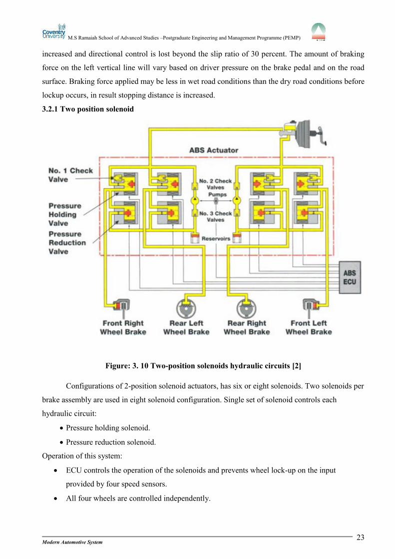
Figure: 3. 10 Two-position solenoids hydraulic circuits [2]
Configurations of 2-position solenoid actuators, has six or eight solenoids. Two solenoids per
brake assembly are used in eight solenoid configuration. Single set of solenoid controls each
hydraulic circuit:
Pressure holding solenoid.
Pressure reduction solenoid.
Operation of this system:
ECU controls the operation of the solenoids and prevents wheel lock-up on the input
provided by four speed sensors.
All four wheels are controlled independently.
Page 33
M.S Ramaiah School of Advanced Studies –Postgraduate Engineering and Management Programme (PEMP)
Modern Automotive System24
3.2.1.1 Pressure holding solenoid
Opens and closes the circuit between the wheel cylinder and the brake cylinder. To open the
position the valve is spring loaded. Valve closes when the current flows in the coil. Additional
release passage is provided by a spring loaded check valve when pressure from the master cylinder
drops.
3.2.1.2 Pressure reduction solenoid
Opens and closes the circuit between the actuator reservoir and the wheel cylinder. In closed
position the valve is spring loaded. The valve compressesthe spring and opens the valve, when
current flows through the coil.
3.3 Discussion on control logic used in the working of complete system with
relevant diagrams and graph.With very simple concept the fuzzy controllers are designed. Fuzzy controller consists of an
input stage, a processing stage and a output stage. In input stage sensors or other inputs are mapped
to get the values and appropriate function of the members. The processing stage invokes each
appropriate rule and generates a result of individual, then the result of rules is combined and lastly
the output stage converts the combination of results back into a specific control output value.
Depending upon the brake temperature, speed and other variables in the system, the ABS
microcontroller makes decision. Cold, Cool, Normal, Warm, Hot are the different states of
temperatures. Transition from one state to next is hard to define.
Fuzzy logic start by defining membership functions using the input temperature.
Figure: 3. 11 Graph of variable temperature [9]
Page 34
M.S Ramaiah School of Advanced Studies –Postgraduate Engineering and Management Programme (PEMP)
Modern Automotive System25
In this function, the input variables state does not jumps from one state to the next. Instead of
jumping the temperature changes, the values are lost in one membership function while gaining the
values in the next. For example, its ranking in the cold category decreases as it becomes more highly
ranked in warmer category.
Figure: 3. 12 Fuzzy logic controlled model for ABS [8]
3.3.1 Anti-lock braking system using fuzzy logic work as follows:
Object in front of a car is detected by a sensor.
Distance between the car and object can be calculated from the signal generated by the
sensor.
By applying brake pressure the car will automatically decelerate, when the object is certain
distance away from the car.
A safe separation distance is maintained in order to control the car speed when the object in
front of the car is moving.
If the object is stationary then the car will stop before hitting the object.
After braking, in order to maneuver the car past object manual braking system override will
be applied.
To calculate the brake pressure needed to safely control the car and the cars closing speed as
inputs the distance between the car and the object is used by the fuzzy controller.
Page 35
M.S Ramaiah School of Advanced Studies –Postgraduate Engineering and Management Programme (PEMP)
Modern Automotive System26
Figure: 3. 13 Fuzzy control membership for speed [8]
Figure: 3. 14 Fuzzy control membership for distance [8]
Figure: 3. 15 Fuzzy control membership for brake pressure [8]
3.4 Key features of implementation on any vehicle case study.3.4.1 Mercedes Sensotronic Brakes
Sensotronic brake control system (SBC) is another brake assist which is used by Mercedes
on some of its vehicle. There is no vacuum booster present in this electronic braking system.
Pressure is used from the ABS pump and accumulator for normal braking as well as ABS braking
and braking assist. In this system the conventional master cylinder is not there for fail-safe backup.
Two Hall Effect sensors in one unit are used as pedal pressure sensor in master cylinder, and pedal
simulator to simulate the feel of a conventional brake system.
Page 36
M.S Ramaiah School of Advanced Studies –Postgraduate Engineering and Management Programme (PEMP)
Modern Automotive System27
In the year 2001 Sensotronic was introduced in Europe, and in 2003 on U.S SL-class and E-
class cars. On SL-class models, Sensotronic was still being used but on E-class models 2006 it was
discontinued due to recall problems of wiring harness and control module glitches problems. Brakes
revert to conventional braking without power assist, when the fault causes the system to shut down.
Sensotronic brake system combines brake assist, Anti-lock braking, brake system pre-
charging and stability control in one integrated system. Collusion warnings or automatic braking is
not provided in this system as with pre-safe braking.
Figure: 3. 16 Sensotronic brake control setup [7]
In this system as soon as the doors on the wheels are unlocked the system is activated and
also when the ignition is turned on by driver or stepped on the brake pedal. By immediately
checking all the sensors it performs a pre-drive self check, operating the ABS pump and applying
pressure to the calipers. While the car is being driven it repeats this self-check every 16 brake
applications.
When the ignition is turned off and the vehicle has remained stationary without touching the
brake pedal the Sensotronic system remains active for up to two minutes. The system will remain
active for another four minutes by touching the brake pedal. The Sensotronic systems time out after
Page 37
M.S Ramaiah School of Advanced Studies –Postgraduate Engineering and Management Programme (PEMP)
Modern Automotive System28
30 seconds, in case if keyless entry systems are used to lock the doors. This is important to know
that the brake will apply themselves if the brake pedal is moved, activating the brake system. And
for deactivation of the system, Doors to be locked after removing the keyless entry fob from the
vehicle. To avoid accidental activation of the system move the key out of range from the vehicle.
After 30 seconds, the Sensotronic system should time out and go into sleep mode. While any brake
work is being performed do not unlock the vehicle and do not touch the brake pedal. Once the work
has been completed, the following procedures are to reactivate the system.
Turn on the ignition.
Turn off the ignition, wait for five seconds and then turn it back on.
Rotate the left rear wheel in the forward direction two revolutions within three seconds, and
then stop. With wheels off the ground.
Rotate the left front wheel two revolutions in the forward direction within 60 seconds after
completing the above step.
The brakes are applied automatically by the Sensotronic system and flashes the brake lights
three times to signal the system has been reactivated. After a quick self-check it applies the
front and rear brakes several times in quick successions. The braking will stop after 50
seconds.
Turn off the ignition, and then lower the vehicle to the ground.
Press brake pedals five to ten times, starting the engine. If any faults are found, fault message
on the drivers display is displayed. To clear the fault, repetition of activation procedure is
necessary.
3.4.2 Benefits of using Sensotronic braking control
3.4.2.1 Brake pedal are electronics instead of a vacuum
In other system, when the brake pedal is applied, applied pressure moves a piston rod which
is linked to the master brake cylinder and the brake booster. Pressure in a brake lines is build by
master cylinder, then presses the brake pads against the brake discs via the wheel cylinder.
In Sensotronic brake system control, a large number of the mechanical components are
replaces by electronics. Brake boosters are absent, instead the pressure inside the master brake
cylinder and the speed with which the brake pedal is operated is gauged through sensors, and these
data are in the form of electronic pulse to the SBC computers.
Page 38
M.S Ramaiah School of Advanced Studies –Postgraduate Engineering and Management Programme (PEMP)
Modern Automotive System29
3.4.2.2 Control unit: pressure modulators for each wheel
In electro hydraulic brake, the central control unit is the centerpiece which is under the
bonnet. Mechanical and electronics provides the benefits at this place. The sensors, valves, electric
pump, microcomputer and software work together and provide good braking management. The
sensors signals from the other electronic assistance are also received by the SBC. SBC Calculates
the brake force separately for the each wheel. The pressure of the brake fluid is between 140-160
bars in the high pressure reservoir ensuring shorter response when compared to conventional brake
systems. One more advantage using SBC is maximum braking power is available even when engine
is switched off. The hydraulic unit comprises four also called pressure modulators. They calculate
the required brake pressure and passes to the brakes. In this way the deceleration and the driving
stability is achieved by the microcomputers while each wheel is slowed down. Pressure sensors
present in the wheel monitor these processes.
3.4.2.3 Emergency braking: stopping distance reduced
Using sensors, Sensotronic brake control includes the high dynamics during pressure build-
up and monitors the behavior of vehicle. Emergency braking: SBC recognizes the driver movement
from the accelerator to the brakes pedal as a clue to an emergency stop and response automatically.
With the help of high pressure reservoir, the brake pressure is increased inside the brake lines and
presses the brake pads to the brake discs so to get a tight grip when the driver presses the brake
pedal. As the result of this, the stopping distance using SBC is reduced compare to conventional
braking system.
3.4.2.4 Driving stability: precise braking impulses for perfect ESP performance
Sensotronic worth is not only proved in emergency braking, but also in other critical
situations. When the risk of swerving in this conditions, the system interact with ESP which keep the
vehicle safely through brake impulses précised at the wheel or by engine speed reduction. The
dynamic and precision is achieved by SBC, with the help of faster and more accurate braking
impulses from SBC high pressure reservoir.
3.4.2.5 Braking in corners:greater safety due to variable brake force distribution
When braking in corners, more safety is provided by SBC than conventional braking system.
These is where the force distribution is divided to each wheels is of particular advantage to car
steering comfort. While in conventional brake system the pressure is distributed equally to inner and
outter wheels. As per the situations SBC assign the brake forces. Hence the outter wheel pressure is
automatically increased by the system because the higher vertical forces allow for great braking
force and at the same time the inner wheel braking force is decreased
Page 39
M.S Ramaiah School of Advanced Studies –Postgraduate Engineering and Management Programme (PEMP)
Modern Automotive System30
3.5 You are also required to comment on the benefits got through solving this
assignments and whether assignment was able to access module learning
outcomes or not?Assignment helped to learn about the following in part A.
The transmission requirement in the vehicle.
The different types of transmissions.
The transmission components.
The advantages and disadvantages of the transmission.
The latest technology of transmission implemented in automotive field.
And in Part B and Part C about
Requirement of brakes.
Regulatory requirements for braking in cars.
Hydraulic and pneumatic system existence in braking system.
Different types of hydraulic system layouts.
Disadvantages and limitations of conventional braking system.
New technologies and development to overcome the limitations of conventional braking
system.
ABS existence in braking system.
Advantages of ABS.
Components, construction and working principle of ABS.
Study of particular vehicle braking system.
Yes the assignments was able to assess the module learning outcomes by making us to search,
read and understand about the technologies and also came to realize the growth of automotive
industry.
Page 40
M.S Ramaiah School of Advanced Studies –Postgraduate Engineering and Management Programme (PEMP)
Modern Automotive System31
BIBILOGRAPHY______________________________________________________________________________
1. http://www.drivingfast.net/technology/abs.htm#axzz1dHC7e5Wu
2. Lexus technical training document
3. Bosch, Automotive hand book 7th edition
4. http://www.autorepairintheknow.com/servicing-your-front-brakes/
5. http://www.agcoauto.com/content/plugins/p2_news/printarticle.php?p2_articleid=187
6. http://autorepair.about.com/library/a/1h/bl623h.htm
7. http://www.import-car.com/Article/71660/Brake_Safe.aspx
8. Journal of intelligent and fuzzy systems 7 (1999) 47-54 ISSN 1064-1246, M.A Jarrah
9. http://en.wikipedia.org/wiki/Fuzzy_logic
10. http://cliffcheat.blogspot.com/2010/12/antilock-braking-system-components.html
11. Automotive technology 5th edition, Jack Erjavec
12. http://www.automotifme.com/review-2012-ml550-suv/
13. http://www.hyundai.com.au/Vehicles/Getz/Safety-Performance/default.aspx
14. http://f1-dictionary.110mb.com/braking_tech.html
15. http://www.cartradeindia.com/car-bike-news/brake-systems-in-cars-113490.html
16. http://www.familycar.com/brakes.htm
17. http://healthandsafetyontario.ca/HSO/media/WSN/Resources/Downloads/Braking-
Systems-Compliance-and-Testing.pdf?ext=.pdf
18. http://tractors.wikia.com/wiki/Semi-automatic_transmission
19. http://www.csa.com/discoveryguides/auto/review6.php
20. http://www.cartradeindia.com/auto-guides/safety-systems-and-security-features-in-
cars-113752.html
21. http://www.yuvaengineers.com/?p=737
22. http://www.drivingfast.net/car-control/braking.htm#axzz1cZj8qHuD