71
Ver.1.1 Mar 23, 2006 Fully Automated Protein Synthesizer GenDecoder 1000A2 Instruction Manual
| Date post: | 08-Apr-2018 |
| Category: |
Documents |
| Upload: | hoangthuan |
| View: | 221 times |
| Download: | 1 times |
Ver.1.1 Mar 23, 2006
Fully Automated Protein Synthesizer
GenDecoder 1000A2
Instruction Manual

Ver.1.1 Mar 23, 2006. -1-
Table of Contents
■1. Outline ......................................................................................................................... 2 ■2. Description and Type................................................................................................... 2 ■3. Features of the Equipment .......................................................................................... 2 ■4. Basic Specifications..................................................................................................... 3 ■5. Exterior ........................................................................................................................ 4 ■6. Workbench Layout 1.................................................................................................... 4 ■7. Workbench Layout 2.................................................................................................... 5 ■8. Vicinity of the Centrifuge.............................................................................................. 5 ■9. Vicinity of the Robot Arm ............................................................................................. 6 ■10. Name and Function of Each Part ............................................................................. 6 ■11. Samples and Consumables ..................................................................................... 8 ■12. Accessories and Options ......................................................................................... 8 ■13. Types of Operating Programs .................................................................................. 9 ■14. Operation Procedure for Starting the Equipment................................................... 10 ■15. Screening-1 Layout ................................................................................................ 14 ■16. Screening-2 Layout ................................................................................................ 15 ■17. Screening-4 Layout ................................................................................................ 16 ■18. Plasmid-1 Layout.................................................................................................... 17 ■19. Plasmid -2 Layout................................................................................................... 18 ■20. Method of Installing Reagent 5 .............................................................................. 20 ■21. Method of Setting the Supernatant Removal Pad ................................................. 22 ■22. Outline of the Protocol for the Screening system (for 96 samples) ....................... 25 ■23. Outline of the Protocol for the Plasmid system (for 96 samples) .......................... 28 ■24. Operation Programs and Operation Commands ................................................... 32 ■25. Transfer of Operation Program (registration in the equipment)............................. 32 ■26. Transferring the Control Programs and Installing Related Application Programs in
the PC..................................................................................................................... 32 ■27. Hierarchical Structure of the Touch Panel Display................................................. 34 ■28. Description of Each Page of the Touch Panel Display........................................... 35 ■29. Centrifuge............................................................................................................... 66 ■30. Index....................................................................................................................... 69 ■31. Amendment History................................................................................................ 69

Ver.1.1 Mar 23, 2006. -2-
■1. Outline
This equipment is a fully automated protein synthesizer which was developed by Professor Endo of Ehime University using cell-free protein synthesis technology. Among the above methods for synthesize protein, the Bilayer method can be used in this equipment. And based on the origin of template, two systems (1) Screening system and (2) Plasmid system can be mounted.
■2. Description and Type
Fully Automated Protein Synthesizer GenDecoder 1000A2
■3. Features of the Equipment
(1) Processes multiple samples. Screening system protocol permits up to 384 kinds of protein to be synthesized from one batch. Plasmid system protocol permits up to 192 kinds of protein to be synthesized from one batch.
(2) Contains a centrifuge with a temperature regulating function. Because this equipment contains a centrifuge with a temperature regulating function, it permits the following processes to be performed automatically. ① Ethanol precipitation ② Filtering of Plasmid system
(3) Has a supernatant removal unit This equipment contains a supernatant removal unit that unfailingly removes the supernatant after ethanol has been precipitated.
(4) Performs everything from transcription to completion of translation. This single piece of equipment can perform a series of processes from transcription in which mRNA is made from a template, ethanol precipitation, to translation.

Ver.1.1 Mar 23, 2006. -3-
■4. Basic Specifications
Synthesizing method: Cell-free protein synthesis using solution extracted from wheat germ Number of samples processed: 1, 2 or 4 96-hole plates (Use or non-use can be set in row units.) Template: Dispensed in advance on a commercially available PCR plate. Reaction plate: Uses commercially available microtiter plate (MTP). When using 96 sample of Screening system, uses one reaction the MTP
and one dummy plates. When using 192 sample of Screening system, uses two reaction the
MTP. When using 384 sample of Screening system, uses four reaction the
MTP. When using 96 samples of Plasmid system, uses two reaction the MTP
and two dummy plates. When using 192 samples of Plasmid system, uses four reaction the MTP
plates.
Dispensing tip: Two types of commercially available tips For 300 ml (dispenser 1), for 20 m1 (dispenser 2) Reagents used:
(1) Screening system ① Transcription reaction solution ② Ethanol mixture solution ③ Dedicated wheat germ extract ④ Dedicated translation buffer (2) Plasmid system ① Transcription reaction solution ② Ethanol mixture solution ③ Dedicated wheat germ extract ④ Dedicated translation buffer ⑤ Milli-Q
Centrifuge specifications: Centrifuge with cooling function, Max centrifugal force 4000 ´ g (4800 rpm)
Display and operation section: Large touch panel display Power source: 100 VAC, 15 A ´ 2 lines External dimensions and weight: W 1560 mm ´ H 1960 mm ´ D 1070 mm, Approx. 600 kg Installation conditions: 20 – 40°C. Condensation below 80% humidity is not allowed. Processing capacity: Protein synthesis is completed in 26 hours from 1, 2, 4 ´ 96 samples.

Ver.1.1 Mar 23, 2006. -4-
■5. Exterior
■6. Workbench Layout 1
Pull-out type touch panel
UV lamp switch
Power switch
Emergency shutdown switch
Waste box
Folding doors
Supernatant removal unit Incubator Reagent tub
Centrifugal adapter lifter
Tip stage
Waste gate MTP
stages
Cap rack
Breaker
Centrifuge panel
Sliding doors
Centrifuge
PCR stages

Ver.1.1 Mar 23, 2006. -5-
■7. Workbench Layout 2
■8. Vicinity of the Centrifuge
Tip 1 (for 300 ml)
Centrifuge removal port
Tip 2 (for 20 ml)
Centrifugal bucket fixing unit
Tip 1
Home position stop unit
Centrifugal adapter Centrifugal adapter lifter
New water absorption pad Old water absorption pad
Ver.1.1 Mar 23, 2006. -6-
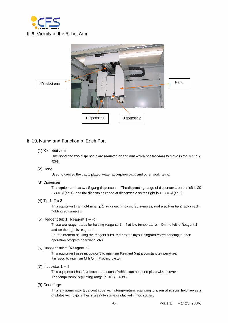
■9. Vicinity of the Robot Arm
■10. Name and Function of Each Part
(1) XY robot arm One hand and two dispensers are mounted on the arm which has freedom to move in the X and Y axes.
(2) Hand Used to convey the caps, plates, water absorption pads and other work items.
(3) Dispenser The equipment has two 8-gang dispensers. The dispensing range of dispenser 1 on the left is 20 – 300 ml (tip 1), and the dispensing range of dispenser 2 on the right is 1 – 20 ml (tip 2).
(4) Tip 1, Tip 2 This equipment can hold nine tip 1 racks each holding 96 samples, and also four tip 2 racks each holding 96 samples.
(5) Reagent tub 1 (Reagent 1 – 4) These are reagent tubs for holding reagents 1 – 4 at low temperature. On the left is Reagent 1 and on the right is reagent 4. For the method of using the reagent tubs, refer to the layout diagram corresponding to each operation program described later.
(6) Reagent tub 5 (Reagent 5) This equipment uses incubator 3 to maintain Reagent 5 at a constant temperature. It is used to maintain Milli-Q in Plasmid system.
(7) Incubator 1 – 4 This equipment has four incubators each of which can hold one plate with a cover. The temperature regulating range is 10°C – 40°C.
(8) Centrifuge This is a swing rotor type centrifuge with a temperature regulating function which can hold two sets of plates with caps either in a single stage or stacked in two stages.
Dispenser 2 Dispenser 1
XY robot arm Hand
Ver.1.1 Mar 23, 2006. -7-
(9) Centrifugal bucket fixing unit: Bucket lock This unit maintains the bucket horizontal. It can correct a tilt of up to 30°.
(10) Home position stop unit This unit rotates the rotor in the centrifuge, and positions bucket 1 and bucket 2.
(11) Centrifugal adapter lifter This equipment uses a centrifugal adapter for installing plates in the centrifuge. The centrifugal adapter lifter is intended for installing plates on, or removing them from, the centrifugal adapter.
(12) Supernatant removal unit This unit removes the supernatant after ethanol has been precipitated. There is a rack for water absorption pads at the front of the equipment.
(13) Waste gate This is the port into which tips are discarded.
(14) Touch panel display This is a color display with a touch input function. The various settings, preparatory work, startup and other operations are performed using this display.
(15) Cap rack There are three racks. The left one (CAP1) is for the PCR caps, and the center and right ones (CAP3 and 3) are for the MTP caps.
(16) PCR stages These areas are for setting the PCR plates on which the template was dispensed. They are cooled to a temperature of 15°C. The stages are numbered 1 to 4 in sequence from the rear.
(17) MTP stages These areas are for setting the reaction plates (MTP plate).
Ver.1.1 Mar 23, 2006. -8-
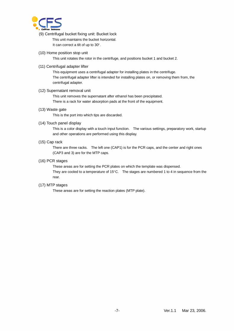
■11. Samples and Consumables
The following consumables are used with this equipment.
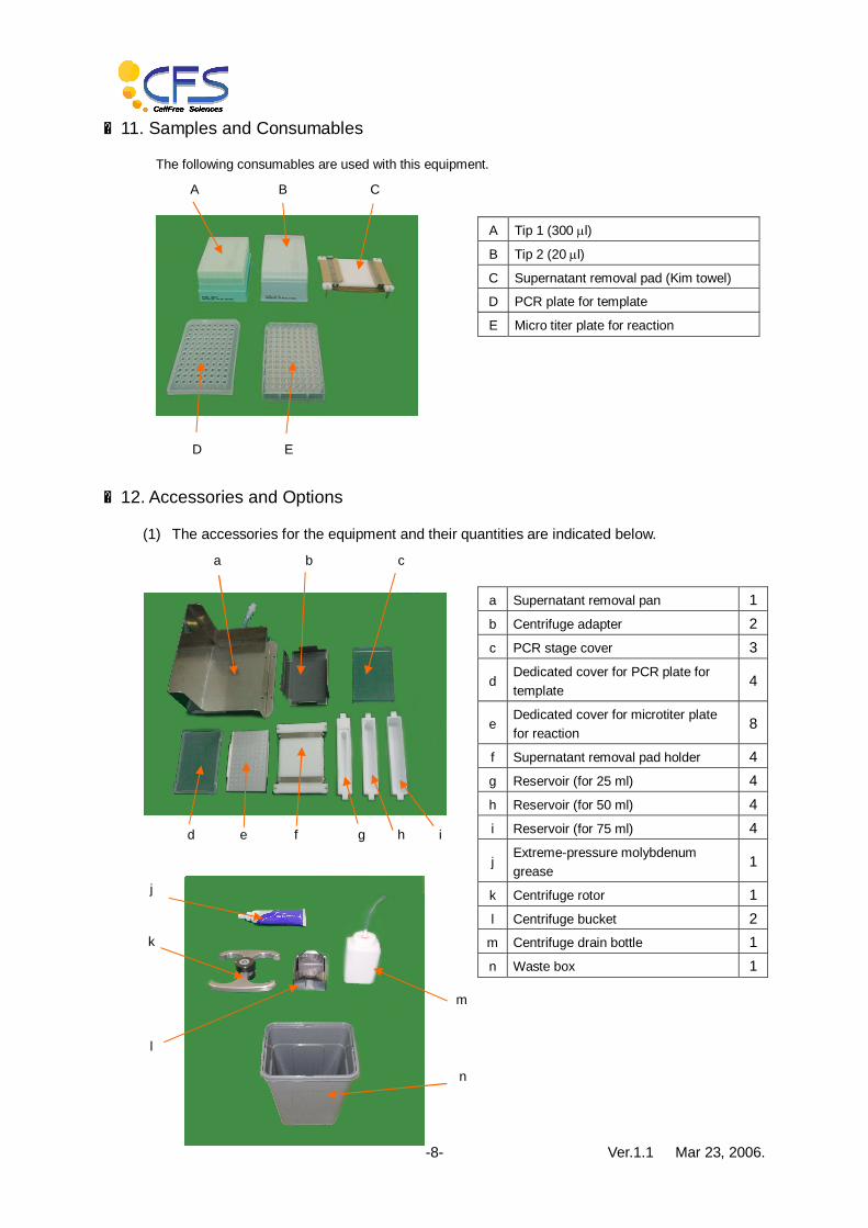
■12. Accessories and Options
(1) The accessories for the equipment and their quantities are indicated below.
E D
B C A
d e f h g i
c b a
k
l
m
n
A Tip 1 (300 ml)
B Tip 2 (20 ml)
C Supernatant removal pad (Kim towel)
D PCR plate for template
E Micro titer plate for reaction
a Supernatant removal pan 1 b Centrifuge adapter 2 c PCR stage cover 3
d Dedicated cover for PCR plate for template 4
e Dedicated cover for microtiter plate for reaction 8
f Supernatant removal pad holder 4 g Reservoir (for 25 ml) 4 h Reservoir (for 50 ml) 4 i Reservoir (for 75 ml) 4
j Extreme-pressure molybdenum grease 1
k Centrifuge rotor 1 l Centrifuge bucket 2
m Centrifuge drain bottle 1 n Waste box 1
j

Ver.1.1 Mar 23, 2006. -9-
(2) The options for the equipment are indicated below. They are used with Plasmid system.
■13. Types of Operating Programs
1. Screening system 1. Screening-1 Uses one MTP for 96 sample and reaction + one dummy plate. 2. Screening-2 Uses two MTP for 192 sample and reaction. 3. Screening-4 Uses four MTP for 384 sample and reaction.
2. Plasmid system 1. Plasmid-1 Uses two MTP for 96 sample and reaction + two dummy plates. 2. Plasmid-2 Uses four MTP for 196 sample and reaction.
o
r
p
q
o Stand for incubator 3 heater
p Cover for incubator 3
q Cover for Reagent 5
r Reagent 5 (for 600 ml)

Ver.1.1 Mar 23, 2006. -10-
■14. Operation Procedure for Starting the Equipment
(1) Start operation using the following procedure. First, ensure that the breaker is closed, and then switch ON the power.
Note: Before initialization, check the following items. When the following items marked * are applicable, perform operation using “Basic Output” in “Maintenance menu”, or “Preparation”
Unit name Check items
Reagent tub Is the cover closed?
Centrifugal adapter lifter * Is the adapter in the lowered position? Is the adapter set?
Centrifuge home position stop * Is the centrifuge in the raised position?
Centrifuge Is the plate inserted? Is the bucket set?
Incubator * Is the cover closed? Is the plate on the incubator?
Supernatant removal Is the plate on the supernatant removal? Is the pan set?
Workbench Is there any spilled reagent?
Drain tank Is the waste box installed?
(2) Close all of the doors, then start “Preparation”, and carry out “Equipment initialization”. ※ Upon completion of initialization, “Not done” changes to “Done”.
(3) Normally set the program of the centrifuge to No.1. ※ Check the rotational speed and setting temperature.
Breaker Power switch

Ver.1.1 Mar 23, 2006. -11-
Initial settings of centrifuge
Program No. Rotational speed Time Temperature
1 4800 rpm HD 4℃
2 4800 rpm HD 26℃
(4) Set the samples required by the desired operation program in the equipment. For the method of setting the samples, refer to the data shown later in this manual. (Items 13 to 20) Note: After setting the samples, recheck the doors.
(5) Start “Parameter”, and set the parameters.
※ When a parameter is selected, it turns blue.
(6) Using the “Program menu” screen, start the desired program.
Centrifuge panel

Ver.1.1 Mar 23, 2006. -12-
※ After initialization, “Do not start” changes to “Start”.
Ver.1.1 Mar 23, 2006. -13-
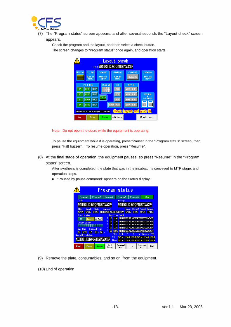
(7) The “Program status” screen appears, and after several seconds the “Layout check” screen appears.
Check the program and the layout, and then select a check button. The screen changes to “Program status” once again, and operation starts.
Note: Do not open the doors while the equipment is operating. To pause the equipment while it is operating, press “Pause” in the “Program status” screen, then press “Halt buzzer”. To resume operation, press “Resume”.
(8) At the final stage of operation, the equipment pauses, so press “Resume” in the “Program status” screen.
After synthesis is completed, the plate that was in the incubator is conveyed to MTP stage, and operation stops. ※ “Paused by pause command” appears on the Status display.
(9) Remove the plate, consumables, and so on, from the equipment.
(10) End of operation
Ver.1.1 Mar 23, 2006. -14-
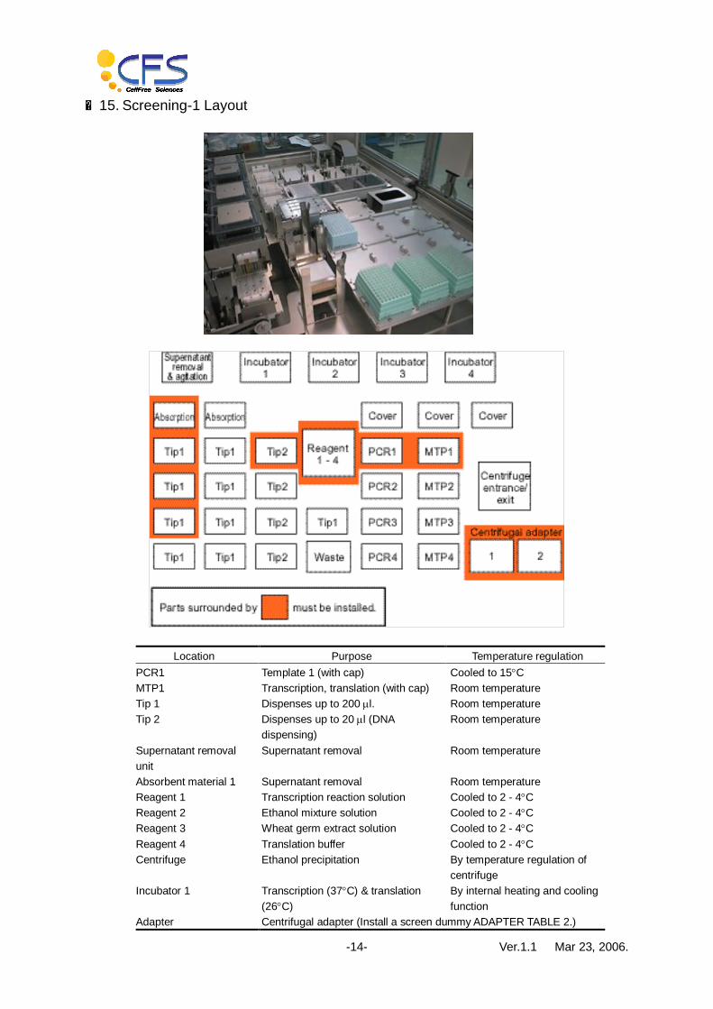
■15. Screening-1 Layout
Location Purpose Temperature regulation
PCR1 Template 1 (with cap) Cooled to 15°C MTP1 Transcription, translation (with cap) Room temperature Tip 1 Dispenses up to 200 ml. Room temperature Tip 2 Dispenses up to 20 ml (DNA
dispensing) Room temperature
Supernatant removal unit
Supernatant removal Room temperature
Absorbent material 1 Supernatant removal Room temperature Reagent 1 Transcription reaction solution Cooled to 2 - 4°C Reagent 2 Ethanol mixture solution Cooled to 2 - 4°C Reagent 3 Wheat germ extract solution Cooled to 2 - 4°C Reagent 4 Translation buffer Cooled to 2 - 4°C Centrifuge Ethanol precipitation By temperature regulation of
centrifuge Incubator 1 Transcription (37°C) & translation
(26°C) By internal heating and cooling function
Adapter Centrifugal adapter (Install a screen dummy ADAPTER TABLE 2.)

Ver.1.1 Mar 23, 2006. -15-
■16. Screening-2 Layout
Location Purpose Temperature regulation PCR1 – 2 Templates 1 - 2 (with cap) Cooled to 15°C MTP1 – 2 Transcription & translation (with cap) Room temperature Tip 1 Dispenses up to 200 ml. Room temperature Tip 2 Dispenses up to 20 ml (DNA
dispensing) Room temperature
Supernatant removal unit
Supernatant removal Room temperature
Absorbent material 1 - 2 Supernatant removal Room temperature Reagent 1 Transcription reaction solution Cooled to 2 - 4°C Reagent 2 Ethanol mixture solution Cooled to 2 - 4°C Reagent 3 Wheat germ extract solution Cooled to 2 - 4°C Reagent 4 Translation buffer Cooled to 2 - 4°C Centrifuge Ethanol precipitation By temperature regulation of
centrifuge Incubator 1 - 2 Transcription (37°C) & translation
(26°C) By internal heating and cooling function
Adapter Centrifugal adapter
Ver.1.1 Mar 23, 2006. -16-
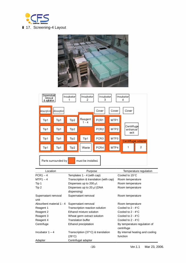
■17. Screening-4 Layout
Location Purpose Temperature regulation PCR1 – 4 Templates 1 - 4 (with cap) Cooled to 15°C MTP1 – 4 Transcription & translation (with cap) Room temperature Tip 1 Dispenses up to 200 ml. Room temperature Tip 2 Dispenses up to 20 ml (DNA
dispensing) Room temperature
Supernatant removal unit
Supernatant removal Room temperature
Absorbent material 1 - 4 Supernatant removal Room temperature Reagent 1 Transcription reaction solution Cooled to 2 - 4°C Reagent 2 Ethanol mixture solution Cooled to 2 - 4°C Reagent 3 Wheat germ extract solution Cooled to 2 - 4°C Reagent 4 Translation buffer Cooled to 2 - 4°C Centrifuge Ethanol precipitation By temperature regulation of
centrifuge Incubator 1 – 4 Transcription (37°C) & translation
(26°C) By internal heating and cooling function
Adapter Centrifugal adapter
Ver.1.1 Mar 23, 2006. -17-
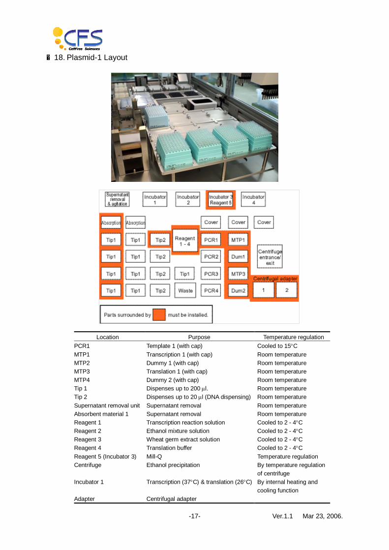
■18. Plasmid-1 Layout
Location Purpose Temperature regulation PCR1 Template 1 (with cap) Cooled to 15°C MTP1 Transcription 1 (with cap) Room temperature MTP2 Dummy 1 (with cap) Room temperature MTP3 Translation 1 (with cap) Room temperature MTP4 Dummy 2 (with cap) Room temperature Tip 1 Dispenses up to 200 ml. Room temperature Tip 2 Dispenses up to 20 ml (DNA dispensing) Room temperature Supernatant removal unit Supernatant removal Room temperature Absorbent material 1 Supernatant removal Room temperature Reagent 1 Transcription reaction solution Cooled to 2 - 4°C Reagent 2 Ethanol mixture solution Cooled to 2 - 4°C Reagent 3 Wheat germ extract solution Cooled to 2 - 4°C Reagent 4 Translation buffer Cooled to 2 - 4°C Reagent 5 (Incubator 3) Mill-Q Temperature regulation Centrifuge Ethanol precipitation By temperature regulation
of centrifuge Incubator 1 Transcription (37°C) & translation (26°C) By internal heating and
cooling function Adapter Centrifugal adapter

Ver.1.1 Mar 23, 2006. -18-
■19. Plasmid -2 Layout
Location Purpose Temperature regulation PCR1 Template 1 (with cap) Cooled to 15°C PCR2 Template 2 (with cap) Cooled to 15°C MTP1 Transcription 1 (with cap) Room temperature MTP2 Transcription 2 (with cap) Room temperature MTP3 Translation 1 (with cap) Room temperature MTP4 Translation 2 (with cap) Room temperature Tip 1 Dispenses up to 200 ml. Room temperature Tip 2 Dispenses up to 20 ml (DNA dispensing) Room temperature Supernatant removal unit Supernatant removal Room temperature Absorbent material 1 - 2 Supernatant removal Room temperature Reagent 1 Transcription reaction solution Cooled to 2 - 4°C Reagent 2 Ethanol mixture solution Cooled to 2 - 4°C Reagent 3 Wheat germ extract solution Cooled to 2 - 4°C Reagent 4 Translation buffer Cooled to 2 - 4°C Reagent 5 (Incubator 3) Mill-Q Temperature regulation Centrifuge Ethanol precipitation By temperature regulation
of centrifuge Incubator 1 - 2 Transcription (37°C) & translation (26°C) By internal heating and
cooling function

Ver.1.1 Mar 23, 2006. -19-
Adapter Centrifugal adapter

Ver.1.1 Mar 23, 2006. -20-
■20. Method of Installing Reagent 5
The followings are the descriptions of the method of installing Reagent 5 in Plasmid system.
(1) Remove the knurled screw from the incubator 3 heater unit.
(2) Remove the heater unit, and place it on the dedicated base.
Note: Ensure that the cable does not interfere with the opening and closing of incubator 4.
Ver.1.1 Mar 23, 2006. -21-
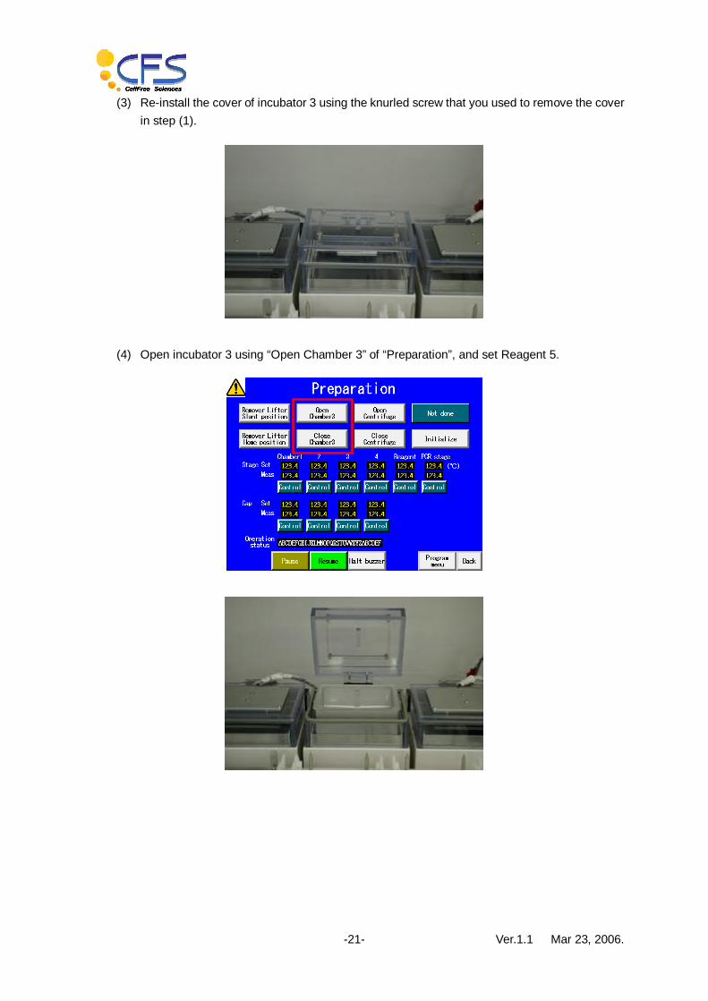
(3) Re-install the cover of incubator 3 using the knurled screw that you used to remove the cover in step (1).
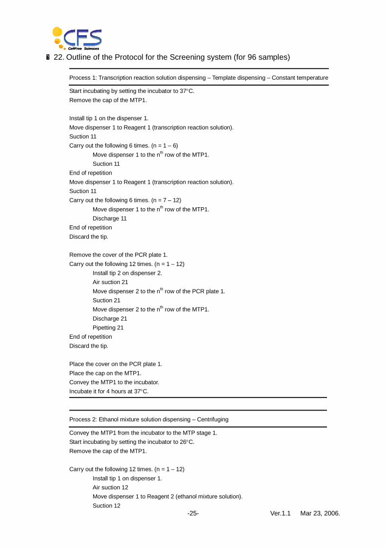
(4) Open incubator 3 using “Open Chamber 3” of “Preparation”, and set Reagent 5.

Ver.1.1 Mar 23, 2006. -22-
■21. Method of Setting the Supernatant Removal Pad
(1) Obtain two Kim towels. Cut one of these roughly into two halves.
(2) Separate “①-1”.

Ver.1.1 Mar 23, 2006. -23-
(3) Install “①-1-1” on one of the supernatant removal pad holder.
Note: Cut the Kim towel so that it does not protrude from the groove.
(4) Fold the second towel, place “①-2” and “①-1-2” on top of each other, cut any superfluous
parts, and clamp the towel securely so that it does not sag.
Note: Set the Kim towel so that it does not protrude at any of the four corners.

Ver.1.1 Mar 23, 2006. -24-
(5) Cut off any superfluous parts.
(6) This completes setting work. When installing the pad in the equipment, ensure that none of
the four corners of the Kim towel is protruding.
(7) This completes setting work.
Ver.1.1 Mar 23, 2006. -25-
■22. Outline of the Protocol for the Screening system (for 96 samples)
Process 1: Transcription reaction solution dispensing – Template dispensing – Constant temperature
Start incubating by setting the incubator to 37°C. Remove the cap of the MTP1. Install tip 1 on the dispenser 1. Move dispenser 1 to Reagent 1 (transcription reaction solution). Suction 11 Carry out the following 6 times. (n = 1 – 6) Move dispenser 1 to the nth row of the MTP1. Suction 11 End of repetition Move dispenser 1 to Reagent 1 (transcription reaction solution). Suction 11 Carry out the following 6 times. (n = 7 – 12) Move dispenser 1 to the nth row of the MTP1.
Discharge 11 End of repetition Discard the tip. Remove the cover of the PCR plate 1. Carry out the following 12 times. (n = 1 – 12)
Install tip 2 on dispenser 2. Air suction 21 Move dispenser 2 to the nth row of the PCR plate 1. Suction 21 Move dispenser 2 to the nth row of the MTP1. Discharge 21 Pipetting 21
End of repetition Discard the tip. Place the cover on the PCR plate 1. Place the cap on the MTP1. Convey the MTP1 to the incubator. Incubate it for 4 hours at 37°C.
Process 2: Ethanol mixture solution dispensing – Centrifuging
Convey the MTP1 from the incubator to the MTP stage 1. Start incubating by setting the incubator to 26°C. Remove the cap of the MTP1. Carry out the following 12 times. (n = 1 – 12)
Install tip 1 on dispenser 1. Air suction 12 Move dispenser 1 to Reagent 2 (ethanol mixture solution). Suction 12

Ver.1.1 Mar 23, 2006. -26-
Move dispenser 1 to the nth row of the MTP1. Discharge 12 Pipetting 12
End of repetition Discard the tip. Place the cap on the MTP1. Convey the MTP1 to the lifter. Raise the lifter. Open the doors of the centrifuge. Adjust centrifuge position 1. Convey the MTP1 + centrifugal adapter to the centrifuge. Adjust the position of centrifuge position 2. Convey the dummy plate + centrifugal adapter to the centrifuge. Close the door of the centrifuge. Wait for 10 minutes. Centrifuge 1 starts.
Process 3: Supernatant removal – Drying – Bilayer dispensing – Incubation
Wait until the centrifuge stops. Open the doors of the centrifuge. Adjust the position of centrifuge position 1. Convey the MTP1 + centrifugal adapter from the centrifuge to the lifter. Adjust the position of centrifuge position 2. Convey the dummy plate + centrifugal adapter from the centrifuge to the lifter. Lower the lifter. Convey the MTP1 to the MTP stage 1. Remove the cap from the MTP1. Convey the MTP1 to the supernatant removal unit. Set the water absorption pad on the MTP1. Carry out supernatant removal. Return the water absorbent pad to its initial position. Convey the MTP1 to the MTP stage 1. Dry up Install tip 1 of dispenser 1. Move dispenser 1 to Reagent 3 (wheat germ extract solution). Suction 13 Carry out the following 6 times. (n = 1 – 6)
Move dispenser 1 to the nth row of the MTP1. Discharge 13
End of repetition Discard the tip. Move dispenser 1 to Reagent 3 (wheat germ extract solution). Suction 13 Carry out the following 6 times. (n = 7 – 12)

Ver.1.1 Mar 23, 2006. -27-
Move dispenser 1 to the nth row of the MTP1. Discharge 13
End of repetition Discard the tip. Carry out the following 12 times. (n = 1 – 12)
Install tip 1 on dispenser 1. Air suction 14 Move dispenser 1 to Reagent 4 (extraction solution). Suction 14 Move dispenser 1 to the nth row of the MTP1. Discharge 14
End of repetition Discard the tip. Place the cap on the MTP1. Convey the MTP1 to the incubator. Incubate it for 20 hours at 26°C.
Process 4: End process
Pause operation of the equipment. Convey the MTP1 from the incubator to the MTP stage 1. Move the hand to the home position. End

Ver.1.1 Mar 23, 2006. -28-
■23. Outline of the Protocol for the Plasmid system (for 96 samples)
Process 1: Transcription reaction liquid dispensing - Template dispensing – Incubating
Start incubating by setting incubator to 37°C. Remove the cap of the MTP1. Install tip 1 on dispenser 1. Move dispenser 1 to Reagent 1 (transcription reaction solution). Suction 11 Carry out the following 6 times. (n = 1 – 6)
Move dispenser 1 to the nth row of the MTP1. Discharge 11
End of repetition Move dispenser 1 to Reagent 1 (transcription reaction solution). Suction 11 Carry out the following 6 times. (n = 7 – 12)
Move dispenser 1 to the nth row of the MTP1. Discharge 11
End of repetition Discard the tip. Remove the cover of the PCR plate 1. Carry out the following 12 times. (n = 1 – 12)
Install tip 2 on dispenser 2. Air suction 21 Move dispenser 2 to the nth row of the PCR plate 1. Suction 21 Move dispenser 2 to the nth row of the MTP1. Discharge 21 Pipetting 21
End of repetition Discard the tip. Place the cover on the PCR plate 1. Place the cap on the MTP1. Convey the MTP1 to incubator 1. Incubate it for 4 hours at 37°C.
Process 2: Dispensing Milli-Q – Centrifuging
Convey MTP1 from incubator 1 to the MTP stage 1. Start incubating by setting incubator to 26°C. Remove the cap from the MTP1. Open the door of incubator 3. Install tip 1 on dispenser 1. Move dispenser 1 to Reagent 5 (Milli-Q). Air suction 114

Ver.1.1 Mar 23, 2006. -29-
Suction 114 Carry out the following 6 times. (n = 1 – 6)
Move dispenser 1 to the nth row of the MTP1. Discharge 114
End of repetition Discard the tip. Install tip 1 on dispenser 1. Move dispenser 1 to Reagent 5 (Milli-Q). Air suction 114 Suction 114 Carry out the following 6 times. (n = 7 – 12)
Move dispenser 1 to the nth row of the MTP1. Discharge 114
End of repetition Discard the tip. Carry out the following 12 times. (n = 1 – 12)
Install tip 1 on dispenser 1. Move dispenser 1 to the nth row of the MTP1. Pipetting 114
End of repetition Discard the tip. Place the cover on the MTP1. Convey the MTP1 to the lifter. Convey the MTP2 (dummy) to the lifter. Raise the lifter. Open the door of the centrifuge. Adjust the position of centrifuge position 1. Convey the MTP1 + centrifugal adapter to the centrifuge. Adjust the position of centrifuge position 2. Convey the MTP2 + centrifugal adapter to the centrifuge. Close the door of the centrifuge. Starting of centrifuging
Process 3: Dispensing ethanol mixture solution in the MTP3.
Remove the cap of the MTP3. Install tip 1 on dispenser 1. Carry out the following 12 times. (n = 1 – 12)
Air suction 115 Move dispenser 1 to Reagent 2 (ethanol mixture solution). Suction 115
Move dispenser 1 to the nth row of the MTP3. Discharge 115
End of repetition Discard the tip.

Ver.1.1 Mar 23, 2006. -30-
Place the cap on the MTP1.
Process 4: Transferring the supernatant – Centrifuging
Wait for the centrifuge to stop. Open the door of the centrifuge. Adjust the position of centrifuge position 1. Convey the MTP1 + centrifugal adapter from the centrifuge to the lifter. Adjust the position of centrifuge position 2. Convey the MTP2 + centrifugal adapter from the centrifuge to the lifter. Lower the lifter. Convey the MTP1 to the MTP stage 1. Convey the MTP2 to the MTP stage 1. Remove the cover of the MTP1. Remove the cover of the MTP3. Carry out the following 12 times. (n = 1 – 12)
Install tip 1 on the dispenser. Air suction 111
Move dispenser 1 to the nth row of the MTP1. Suction 111 Move dispenser 1 to the nth row of the MTP3. Discharge 111 Pipetting 111
End of repetition Discard the tip. Place the cap on the MTP1. Place the cap on the MTP3. Convey the MTP3 to the lifter. Convey the MTP4 (dummy) to the lifter. Raise the lifter. Open the door of the centrifuge. Adjust the position of centrifuge position 1. Convey the MTP3 + centrifugal adapter to the centrifuge. Adjust the position of centrifuge position 2. Convey the MTP4 + centrifugal adapter to the centrifuge. Close the door of the centrifuge. Convey the MTP1 to the MTP3. Convey the MTP2 to the MTP4. Wait for 10 minutes. Centrifuging 1 starts.
Process 5: Supernatant removal – Drying – Bilayer dispensing – Incubation
Wait until the centrifuge stops. Open the doors of the centrifuge. Adjust the position of centrifuge position 1. Convey the MTP3 + centrifugal adapter from the centrifuge to the lifter.
Ver.1.1 Mar 23, 2006. -31-
Adjust the position of centrifuge position 2. Convey the MTP4 + centrifugal adapter from the centrifuge to the lifter. Lower the lifter. Convey the MTP3 to the MTP stage 1. Convey the MTP4 to the MTP stage 2. Remove the cap from the MTP3. Convey the MTP3 to the supernatant removal unit. Set the water absorption pad on the MTP3. Carry out supernatant removal. Return the water absorbent pad to its initial position. Convey the MTP3 to the MTP stage 1. Dry up Install tip 1 of dispenser 1. Move dispenser 1 to Reagent 3 (wheat germ extract solution). Suction 13 Carry out the following 6 times. (n = 1 – 6)
Move dispenser 1 to the nth row of the MTP3 (the position is MTP stage 1). Discharge 13
End of repetition Discard the tip. Move dispenser 1 to Reagent 3 (wheat germ extract solution). Suction 13 Carry out the following 6 times. (n = 7 – 12)
Move dispenser 1 to the nth row of the MTP3 (the position is MTP stage 1). Discharge 13
End of repetition Discard the tip. Carry out the following 12 times. (n = 1 – 12)
Install tip 1 on dispenser 1. Air suction 14 Move dispenser 1 to Reagent 4 (extraction solution). Suction 14 Move dispenser 1 to the nth row of the MTP3 (the position is MTP stage 1). Discharge 14
End of repetition Discard the tip. Place the cap on the MTP3. Convey the MTP3 to the incubator 1. Incubate it for 20 hours at 26°C.
Process 6: End process
Pause operation of the equipment. Convey the MTP3 from the incubator to the MTP stage 1.
Ver.1.1 Mar 23, 2006. -32-
Move the hand to the home position. End
■24. Operation Programs and Operation Commands
The operation programs in this equipment have been created using a PC, based on the work protocol, and are stored as files.
■25. Transfer of Operation Program (registration in the equipment)
To actually operate an operation program created using the PC, it is necessary to transfer it to (register it in) the equipment using the dedicated application program on the PC. The equipment is designed to enable up to 5 operation programs to be registered in it. A registered program can be selected and executed from the operation panel of the equipment.
■26. Transferring the Control Programs and Installing Related Application Programs in the PC
This equipment is an automated machine that is controlled by a sequencer (hereafter called PLC). It requires many operations to set it up for automatic operation. The procedure for doing this is set out below.
(1) Obtain a PC containing the necessary software. The following application software must have been installed in the PC.
1. Keyence KV BUILDER (Ver. 3.5 or higher) 2. Keyence MOTION BUILDER 3. Keyence DATA BUILDER 4. Keyence VT2 BUILDER 5. Microsoft Visual Basic 6.0
(2) In addition to the above, the following project folder for GenDecoder 1000 is necessary.
[GenDecoder 1000 @yyyy-mm-dd] │ ├─ Dmrw: PLC data file and PLC data control software │ ├─ Doc: Document │ ├─ ParameterSetup: Parameter systematic setting and control software │ ├─ Pc: Operation program and operation program control software │ ├─ Pic: PIC program used with this equipment │ ├─ Plc: PLC program │ └─ Vt: VT program
(3) General flow of setup procedure 1. Transferring the PLC program
Transfer (write) the PLC program in the PLC folder to PLC using KV BUILDER. 2. Setting up the H40S stepping motor controller

Ver.1.1 Mar 23, 2006. -33-
Transfer the H40S settings in the PLC folder to PLC using MOTION BUILDER via KV BUILDER. There are two H40S controllers, so transfer settings for both.
3. Transferring the VT program
Transfer (write) the VT program in the VT folder to VT using VT2 BUILDER. 4. Transferring operation programs
Transfer the operation programs in the PC folder (or Program folder below it) to PLC using the operation program transfer software.
5. Standard data transfer
Write the stored standard data as a file in the DMRW folder to PLC using DMRW. 6. Setting up the centrifuge 7. Restarting and initializing the equipment
After restarting the equipment, initialize it. 8. Setting the position of the hand 9. Setting the position of the dispenser 10. Checking operation by automatic operation

Ver.1.1 Mar 23, 2006. -34-
■27. Hierarchical Structure of the Touch Panel Display
Startup screen
↓
Main menu | ├── Preparation | ├── Program menu | ├── Program status | ├── Parameter | └── Maintenance menu | ├── Sensor monitor | ├── Basic output 1 | | Basic output 2 | ├── Remover Up/Down setting | ├── Centrifuge positioning | ├── XY axis setting | ├── Hand Z axis setting | ├── Dispenser Z axis settings | ├── Dispenser 1 setting | ├── Dispenser 2 setting | ├── Temperature setting 1 | | Temperature setting 2 | | Temperature setting 3 | ├── Running monitor | | Log | | Spare units | ├── Hand position 1 – 7 | ├── Dispenser position 1 – 6 | ├── Delete program | └── Command menu | └── Command 1 – 19
Ver.1.1 Mar 23, 2006. -35-
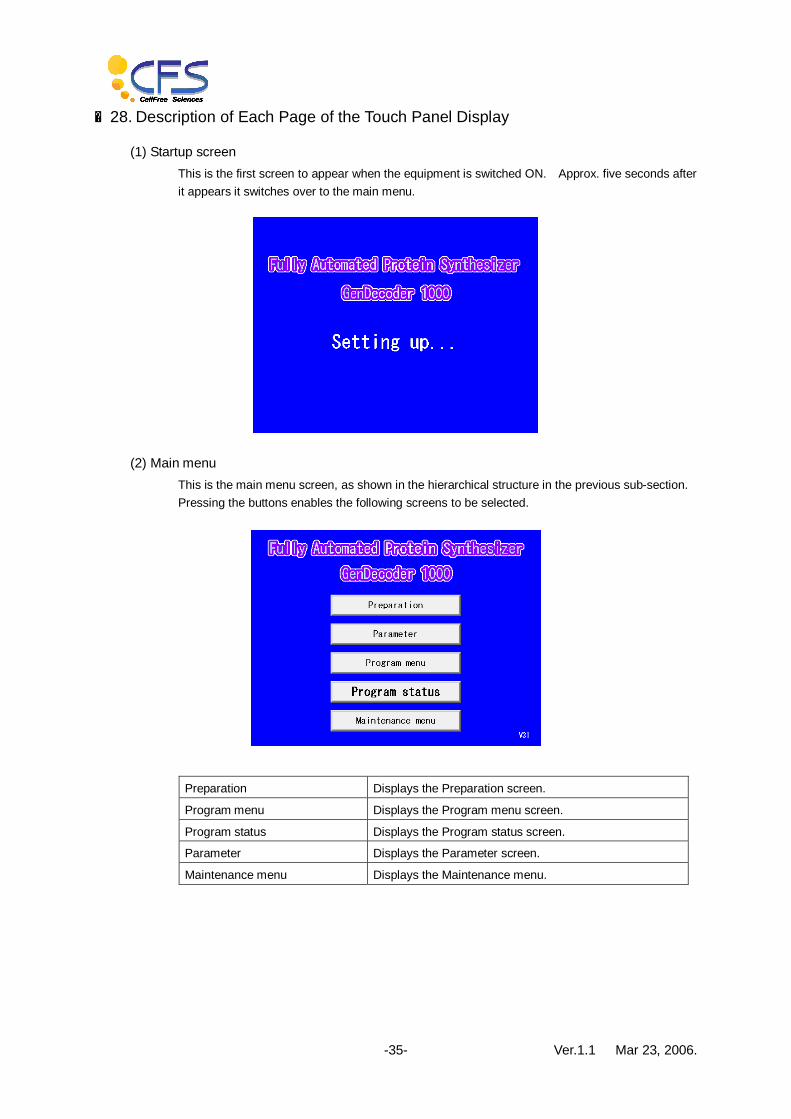
■28. Description of Each Page of the Touch Panel Display
(1) Startup screen This is the first screen to appear when the equipment is switched ON. Approx. five seconds after it appears it switches over to the main menu.
(2) Main menu This is the main menu screen, as shown in the hierarchical structure in the previous sub-section. Pressing the buttons enables the following screens to be selected.
Preparation Displays the Preparation screen.
Program menu Displays the Program menu screen.
Program status Displays the Program status screen.
Parameter Displays the Parameter screen.
Maintenance menu Displays the Maintenance menu.
Ver.1.1 Mar 23, 2006. -36-
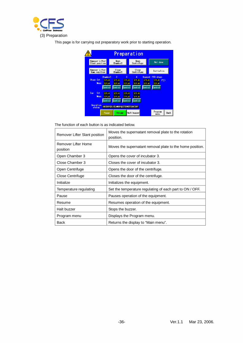
(3) Preparation This page is for carrying out preparatory work prior to starting operation.
The function of each button is as indicated below.
Remover Lifter Slant position Moves the supernatant removal plate to the rotation position.
Remover Lifter Home position
Moves the supernatant removal plate to the home position.
Open Chamber 3 Opens the cover of incubator 3.
Close Chamber 3 Closes the cover of incubator 3.
Open Centrifuge Opens the door of the centrifuge.
Close Centrifuge Closes the door of the centrifuge.
Initialize Initializes the equipment.
Temperature regulating Set the temperature regulating of each part to ON / OFF.
Pause Pauses operation of the equipment.
Resume Resumes operation of the equipment.
Halt buzzer Stops the buzzer.
Program menu Displays the Program menu.
Back Returns the display to “Main menu”.

Ver.1.1 Mar 23, 2006. -37-
(4) Program menu This screen is used to start operation. A maximum of five operation programs can be registered. Select the desired program from these five programs, and press the button. Note: The equipment cannot start operating unless it is initialized.
Be sure to initialize it according to “(3) Preparation”.
The buttons on this screen function as follows when pressed.
Program status Displays the Program status screen.
Preparation Displays the Preparation screen.
Return Returns the display to “Main menu”.
Able to Restart/ Unable to Restart
Restarts the interrupted program.
Start/Unable to Start When pressing this button at “Start”, the operation is started.
In the case of “Unable to Start”, initialize the equipment using “Preparation”.

Ver.1.1 Mar 23, 2006. -38-
(5) Program status This screen appears when the equipment is being started up. It is possible to display another screen while the equipment is operating, however unless there is a particular necessity leave the Program status screen displayed.
The buttons on this screen function as follows when pressed.
Abort Aborts operation.
Pause Pauses operation.
Resume Resumes operation.
Halt buzzer Stops the buzzer.
Command menu Displays the Command menu screen.
Log Moves to the Log screen.
Program menu Displays the Program menu screen.
Back Returns the display to “Main menu”.
Ver.1.1 Mar 23, 2006. -39-
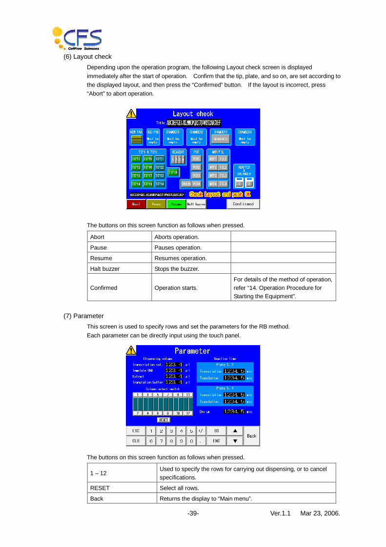
(6) Layout check Depending upon the operation program, the following Layout check screen is displayed immediately after the start of operation. Confirm that the tip, plate, and so on, are set according to the displayed layout, and then press the “Confirmed” button. If the layout is incorrect, press “Abort” to abort operation.
The buttons on this screen function as follows when pressed.
Abort Aborts operation.
Pause Pauses operation.
Resume Resumes operation.
Halt buzzer Stops the buzzer.
Confirmed Operation starts. For details of the method of operation, refer “14. Operation Procedure for Starting the Equipment”.
(7) Parameter This screen is used to specify rows and set the parameters for the RB method. Each parameter can be directly input using the touch panel.
The buttons on this screen function as follows when pressed.
1 – 12 Used to specify the rows for carrying out dispensing, or to cancel specifications.
RESET Select all rows.
Back Returns the display to “Main menu”.
Ver.1.1 Mar 23, 2006. -40-
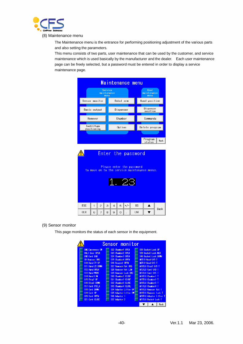
(8) Maintenance menu The Maintenance menu is the entrance for performing positioning adjustment of the various parts and also setting the parameters. This menu consists of two parts, user maintenance that can be used by the customer, and service maintenance which is used basically by the manufacturer and the dealer. Each user maintenance page can be freely selected, but a password must be entered in order to display a service maintenance page.
(9) Sensor monitor This page monitors the status of each sensor in the equipment.

Ver.1.1 Mar 23, 2006. -41-
(10) Basic output 1 This page is used to manually perform a simple output operation of the DC motor, solenoid, and so on.
The function of each button is as indicated below.
Hand Up/Down: Up/Down
Raises or lowers the hand.
Particularly, when lowering the hand, there is a risk of it impacting, so be very careful when operating these buttons.
Hand Open/Close: Open/Close
Opens or closes the hand.
Disp 2 Up/Down: Up/Down
Raises or lowers the dispenser.
Cent Up/Down: Up/Down
Raises or lowers the home position stop unit.
Cent Open/Close: Open/Close
Opens or closes the door of the centrifuge.
Chamber 1 Open/Close: Open/Close
Opens or closes the door of the incubator.
The operation when the Chamber 1 – Chamber 4 Open/Close buttons are pressed are all the same.
Adapter lifter Up/Down: Up/Down
Raises or lowers the centrifuge adapter.
Remover rotation: Back/Forward
Rotates the supernatant removal rotation unit.
Remover lock: Lock/Unlock
Releases or fixes the plate.
Reagent cover: Open/Close
Opens or closes the cover of the reagent tub.
Rotating platform: Forward/Reverse
Rotates the rotating platform in the forward or reverse direction.
Optional
Bucket lock: Up/Down Raises or lowers the bucket fixing unit.
The bucket fixing unit descends only when the centrifuge door is fully open.
Use of Bucket lock: Not use/Select
These buttons change the setting.
In the case of a model that does not have a centrifugal bucket fixing unit, press “Not use”. For a model that has a centrifugal bucket fixing unit, press “Use”.

Ver.1.1 Mar 23, 2006. -42-
Pause Pauses operation.
Resume Resumes operation.
Halt buzzer Stops the buzzer.
▲▼ Moves the page.
Back Returns the display to “Maintenance menu”.
(11) Basic output 2 This page is used to manually perform a simple output operation of a DC motor, solenoid, and so on.
The function of each button is as indicated below.
SV2 Plate lock 1 The MTP1 solenoid operates.
SV3 Plate lock 2 The MTP2 solenoid operates.
SV4 Plate lock 3 The MTP3 solenoid operates.
SV5 Plate lock 4 The MTP4 solenoid operates.
Cent START Starts the centrifuge.
Cent STOP Stops the centrifuge.
Cent PROG1 Selects program 1.
Cent PROG2 Selects program 2.
Cent PROG3 Selects program 3.
Cent PROG4 Selects program 4.
Cent PROG5 Selects program 5.
PAT1 Green lamp The green rotating lamp turns on and off.
PAT2 Yellow lamp The yellow rotating lamp turns on and off.
PAT3 Red lamp The red rotating lamp turns on and off.
BZ1 Buzzer 1 Buzzer 1 sounds.
BZ2 Buzzer 2 Buzzer 2 sounds.
Pause Pauses operation.
Resume Resumes operation.
Halt buzzer Stops the buzzer.
▲▼ Moves the page.
Back Returns the display to “Maintenance menu”.

Ver.1.1 Mar 23, 2006. -43-
(12) Remover Up/Down setting This page is used for making the basic settings for raising and lowering the supernatant removal unit. Each parameter is set to the prescribed value at the factory, so there is normally no need to change it.
The function of each button is as indicated below.
Init Initializes the supernatant removal unit.
Move Moves the supernatant removal unit to the position set using “Destination (mm)”.
Pause Pauses operation.
Resume Resumes operation.
Halt buzzer Stops the buzzer.
Back Returns the display to “Maintenance menu”.

Ver.1.1 Mar 23, 2006. -44-
(13) Centrifuge positioning This page is used for making the basic settings for stopping the centrifuge at the home position. Each parameter is set to the prescribed value at the factory, so there is normally no need to change it.
The function of each button is as indicated below.
Init Initializes the supernatant removal unit.
Move Moves the supernatant removal unit to the position set using “Destination (mm)”.
Pause Pauses operation.
Resume Resumes operation.
Halt buzzer Stops the buzzer.
Back Returns the display to “Maintenance menu”.

Ver.1.1 Mar 23, 2006. -45-
(14) XY axes setting This page is used for making the basic settings and also performing the basic operations of the X- and Y-axes of the robot arm. Each parameter is set to the prescribed value at the factory, so there is normally no need to change it.
The function of each button is as indicated below.
Init X Initializes the X-axis.
Init Y Initializes the Y-axis.
Move Moves the robot arm to the position set in “Destination (mm)”.
Init Initializes the robot arm.
Pause Pauses operation of the robot arm.
Resume Resumes operation of the robot arm.
Halt buzzer Stops the buzzer.
Back Returns the display to “Maintenance menu”.

Ver.1.1 Mar 23, 2006. -46-
(15) Hand Z axis setting This page is used for making the basic settings and also performing the basic operations of the Z-axis of the robot arm. Each parameter is set to the prescribed value at the factory, so there is normally no need to change it.
The function of each button is as indicated below.
Init Initializes the hand Z-axis.
Move Moves the hand Z axis to the position set using “Destination (mm)”.
Pause Pauses operation.
Resume Resumes operation.
Halt buzzer Stops the buzzer.
Back Returns the display to “Maintenance menu”.

Ver.1.1 Mar 23, 2006. -47-
(16) Dispenser Z axis setting This page is used for making the basic settings and also performing the basic operations of the Z-axis of the dispenser. Each parameter is set to the prescribed value at the factory, so there is normally no need to change it.
The function of each button is as indicated below.
Init Initializes the Z-axis of the dispenser.
Move Moves the dispenser in the Z-axis direction to the position specified by “Destination (mm)”.
Pause Pauses operation.
Resume Resumes operation.
Halt buzzer Stops the buzzer.
Back Returns the display to “Maintenance menu”.

Ver.1.1 Mar 23, 2006. -48-
(17) Dispenser 1 setting This page is used for making the basic settings and also performing the basic operations of dispenser 1. Each parameter has been set at the factory, so there is normally no need to change them.
The function of each button is as indicated below.
Init Initializes the settings of dispenser 1.
Suction Performs a suction operation.
Discharge Performs a discharge operation.
Discharge all Discharges all of the sucked solution.
Waste tip Discards the installed tip.
Pause Pauses operation.
Resume Resumes operation.
Halt buzzer Stops the buzzer.
Back Returns the display to “Maintenance menu”.

Ver.1.1 Mar 23, 2006. -49-
(18) Dispenser 2 setting This page is used for making the basic settings and also performing the basic operations of dispenser 2. Each parameter has been set at the factory, so there is normally no need to change them.
The function of each button is as indicated below.
Init Initializes the settings of dispenser 2.
Suction Performs a suction operation.
Discharge Performs a discharge operation.
Discharge all Discharges all of the sucked solution.
Waste tip Discards the installed tip.
Pause Pauses operation.
Resume Resumes operation.
Halt buzzer Stops the buzzer.
Back Returns the display to “Maintenance menu”.
(19) Temperature setting 1 – 3 This page is used to set the temperature of the incubators, reagent tubs and the PCR stage. After the equipment starts operating, the temperature is automatically controlled by the operation program. * Temperature setting 3 is the temperature setting for the heater on the cover side of the incubator.

Ver.1.1 Mar 23, 2006. -50-
(20) Running monitor This page displays the running time of the equipment.
The function of each button is as indicated below.
CLR Sets running time and number of times of each parameter to 0.
Press “CLR” at bottom left twice.

Ver.1.1 Mar 23, 2006. -51-
(21) Log This page displays the operation log of the equipment.
(22) Hand position setting 1 – 7 This screen is used to set each position to which the hand moves.
The function of each button is as indicated below.
Open Hand Opens the hand.
Close Hand Closes the hand.
Carry Carries the work to the specified ID.
Back Returns the carried work to its initial position.
Move The hand moves to each position (ID).
Pause Pauses operation.
Resume Resumes operation.
Halt buzzer Stops the buzzer.
Back Returns the display to “Maintenance menu”.
Ver.1.1 Mar 23, 2006. -52-
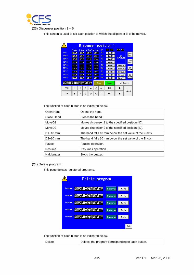
(23) Dispenser position 1 – 6 This screen is used to set each position to which the dispenser is to be moved.
The function of each button is as indicated below.
Open Hand Opens the hand.
Close Hand Closes the hand.
MoveD1 Moves dispenser 1 to the specified position (ID).
MoveD2 Moves dispenser 2 to the specified position (ID).
D1+10 mm The hand falls 10 mm below the set value of the Z-axis.
D2+10 mm The hand falls 10 mm below the set value of the Z-axis.
Pause Pauses operation.
Resume Resumes operation.
Halt buzzer Stops the buzzer.
(24) Delete program This page deletes registered programs.
The function of each button is as indicated below.
Delete Deletes the program corresponding to each button.

Ver.1.1 Mar 23, 2006. -53-
(25) Command menu The command menu is used to call the command 1 – 19 pages from the command menu.
(26) Command 1 This page is used to set the parameters for commands used in the operation programs, and also to operate the commands. Each parameter is set to the specified value at the factory, so normally there is no need to change it.
The function of each button is as indicated below.
Move Moves the hand to the specified ID.
Carry The hand carries the work to the specified ID.
Move Dispenser1 Moves dispenser 1 to the specified ID.
Move Dispenser2 Moves dispenser 2 to the specified ID.
Open Hand Opens the hand.
Close Hand Closes the hand.
Rest Hand The hand moves away from the work position.
Lift Up Adapter The centrifuge adapter rises.
Lift Down Adapter The centrifuge adapter falls.
Turn Table The turntable rotates 180°clockwise. Optional
Pause Pauses operation.
Resume Resumes operation.
Halt buzzer Stops the buzzer.

Ver.1.1 Mar 23, 2006. -54-
Back The screen returns to “Command menu”.
(27) Command 2 This page is used to set the parameters for commands used in the operation programs, and also to operate the commands. Each parameter is set to the specified value at the factory, so normally there is no need to change it.
The function of each button is as indicated below.
TipFull 1 – 2 Returns “REMAIN” to the full count of 108. After operation, the tip count is automatically decremented.
SetTip 1 – 2 Installs the tip corresponding to the ID displayed in “REMAIN”.
WasteTip 1 – 2 Discards the installed tip.
GetTip 1 – 2 Goes to the specified ID to pick up the tip.
PutBackTip 1 – 2 Goes to place the inserted tip in the specified position.
SetMultiple 1 – 2 Counts the rows used for determining the correction multiple for “Dispenser 2 setting”.
Pause Pauses operation.
Resume Resumes operation.
Halt buzzer Stops the buzzer.

Ver.1.1 Mar 23, 2006. -55-
(28) Command 3 This page is used to set the parameters for commands used in the operation programs, and also to operate the commands. Each parameter is set to the specified value at the factory, so normally there is no need to change it.
The function of each button is as indicated below.
SuctionAir 11 – 18 The dispenser performs a suction operation as soon as this button is pressed.
Pause Pauses operation.
Resume Resumes operation.
Halt buzzer Stops the buzzer.
(29) Command 4 This page is used to set the parameters for commands used in the operation programs, and also to operate the commands. Each parameter is set to the specified value at the factory, so normally there is no need to change it.
The function of each button is as indicated below.
Suction 11 – 18 The dispenser performs a suction operation as soon as this button is pressed.
Pause Pauses operation.
Resume Resumes operation.
Halt buzzer Stops the buzzer.
Ver.1.1 Mar 23, 2006. -56-
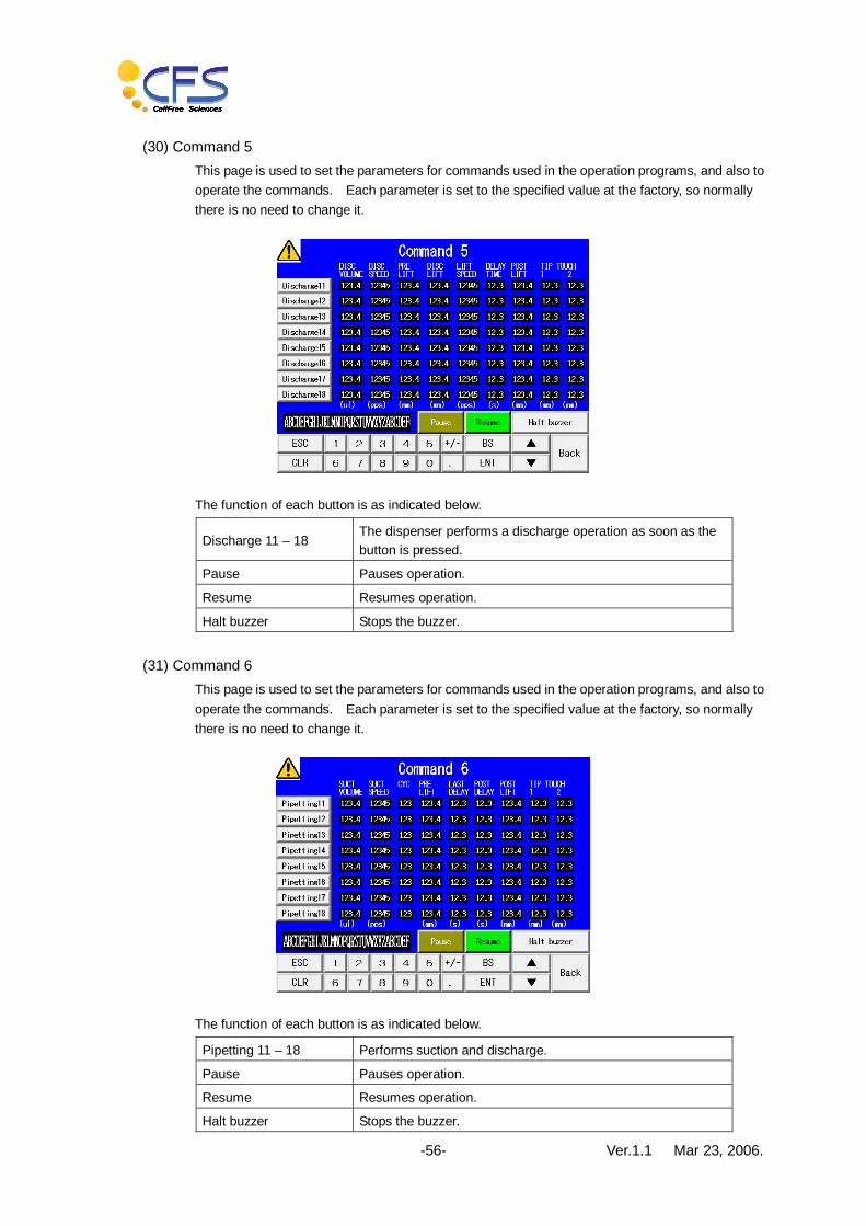
(30) Command 5 This page is used to set the parameters for commands used in the operation programs, and also to operate the commands. Each parameter is set to the specified value at the factory, so normally there is no need to change it.
The function of each button is as indicated below.
Discharge 11 – 18 The dispenser performs a discharge operation as soon as the button is pressed.
Pause Pauses operation.
Resume Resumes operation.
Halt buzzer Stops the buzzer.
(31) Command 6 This page is used to set the parameters for commands used in the operation programs, and also to operate the commands. Each parameter is set to the specified value at the factory, so normally there is no need to change it.
The function of each button is as indicated below.
Pipetting 11 – 18 Performs suction and discharge.
Pause Pauses operation.
Resume Resumes operation.
Halt buzzer Stops the buzzer.

Ver.1.1 Mar 23, 2006. -57-
(32) Command 7 This page is used to set the parameters for commands used in the operation programs, and also to operate the commands. Each parameter is set to the specified value at the factory, so normally there is no need to change it.
The function of each button is as indicated below.
SuctionAir 21 – 28 Performs a suction operation.
Pause Pauses operation.
Resume Resumes operation.
Halt buzzer Stops the buzzer.
(33) Command 8 This page is used to set the parameters for commands used in the operation programs, and also to operate the commands. Each parameter is set to the specified value at the factory, so normally there is no need to change it.
The function of each button is as indicated below.
Suction 21 – 28 Performs a suction operation.

Ver.1.1 Mar 23, 2006. -58-
(34) Command 9 This page is used to set the parameters for commands used in the operation programs, and also to operate the commands. Each parameter is set to the specified value at the factory, so normally there is no need to change it.
The function of each button is as indicated below.
Discharge 21 – 28 Performs a discharge operation.
(35) Command 10 This page is used to set the parameters for commands used in the operation programs, and also to operate the commands. Each parameter is set to the specified value at the factory, so normally there is no need to change it.
The function of each button is as indicated below.
Pipetting 21 – 28 Performs suction and discharge.
Ver.1.1 Mar 23, 2006. -59-
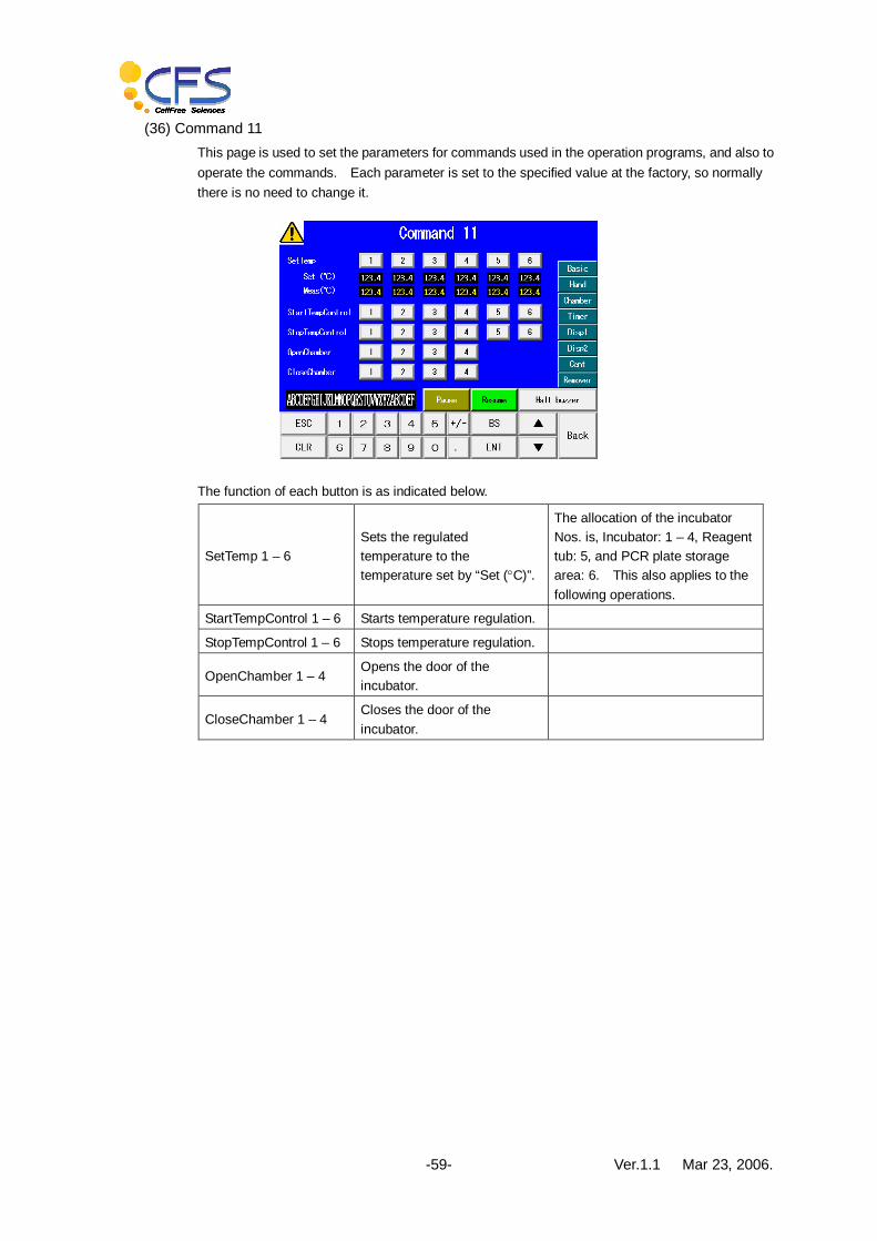
(36) Command 11 This page is used to set the parameters for commands used in the operation programs, and also to operate the commands. Each parameter is set to the specified value at the factory, so normally there is no need to change it.
The function of each button is as indicated below.
SetTemp 1 – 6 Sets the regulated temperature to the temperature set by “Set (°C)”.
The allocation of the incubator Nos. is, Incubator: 1 – 4, Reagent tub: 5, and PCR plate storage area: 6. This also applies to the following operations.
StartTempControl 1 – 6 Starts temperature regulation.
StopTempControl 1 – 6 Stops temperature regulation.
OpenChamber 1 – 4 Opens the door of the incubator.
CloseChamber 1 – 4 Closes the door of the incubator.

Ver.1.1 Mar 23, 2006. -60-
(37) Command 12 This page is used to set the parameters for commands used in the operation programs, and also to operate the commands. Each parameter is set to the specified value at the factory, so normally there is no need to change it.
The function of each button is as indicated below.
SetCapTemp 1 – 4 Sets the temperature whose temperature and temperature regulation of the cap is specified.
StartCapHeating 1 – 4 Starts temperature regulation of the cap.
StopCapHeating 1 – 4 Stops temperature regulation of the cap.
(38) Command 13 This page is used to set the parameters for commands used in the operation programs, and also to operate the commands. Each parameter is set to the specified value at the factory, so normally there is no need to change it.
The function of each button is as indicated below.
SetTimer 1 – 8 Sets delay timers 1 – 8 to t minutes (accuracy 0.1 minute), and starts the delay. The end of the delay time is detected by WaitTimer 1 – 8.
WaitTimer 1 – 8 The equipment waits for the end of the delay time of delay timers 1 – 8.

Ver.1.1 Mar 23, 2006. -61-
(39) Command 14 This page is used to set the parameters for commands used in the operation programs, and also to operate the commands. Each parameter is set to the specified value at the factory, so normally there is no need to change it.
The function of each button is as indicated below.
Centrifuge 1 – 8 Starts the centrifugal operation using the specified program for the specified period.
WaitCentrifuge The equipment waits for the end of the centrifugal operation taking place.
StopCentrifuge Forcibly stops the centrifugal operation.
SelCentProg 1 – 5 Used to select the program.
RotorFree Releases the home position stop unit to free the rotor.
OpenCentrifuge Opens the door of the centrifuge.
OpenHalfCentrifuge Half-opens the door of the centrifuge.
CloseCentrifuge Closes the door of the centrifuge.
CentrifugePosition 1 – 2 The rotor moves to position 1 or position 2.

Ver.1.1 Mar 23, 2006. -62-
(40) Command 15 This page is used to set the parameters for commands used in the operation programs, and also to operate the commands. Each parameter is set to the specified value at the factory, so normally there is no need to change it.
The function of each button is as indicated below.
Remove 1 – 4 Performs a supernatant removal operation.
Remove 2-4 are spare, so they cannot be used at present.
Shake 1 – 4 Performs a supernatant removal operation for the set number of cycles.
Shake 2-4 are spare, so they cannot be used at present.
Set Pad Sets a new absorption pad in the supernatant removal unit.
Take Pad Removes the absorption material in the supernatant removal unit and places it in the storage area.
Rest Hand Moves the hand from the present position to the front.

Ver.1.1 Mar 23, 2006. -63-
(41) Command 16 This page is used to set the parameters for commands used in the operation programs, and also to operate the commands. Each parameter is set to the specified value at the factory, so normally there is no need to change it.
The function of each button is as indicated below.
SuctionAir111 – 115 The dispenser performs a suction operation as soon as this button is pressed.
Pause Pauses operation.
Resume Resumes operation.
Halt buzzer Stops the buzzer.
(42) Command 17 This page is used to set the parameters for commands used in the operation programs, and also to operate the commands. Each parameter is set to the specified value at the factory, so normally there is no need to change it.
The function of each button is as indicated below.
Suction 111 – 115 The dispenser performs a suction operation as soon as this button is pressed.
Pause Pauses operation.
Resume Resumes operation.
Halt buzzer Stops the buzzer.

Ver.1.1 Mar 23, 2006. -64-
(43) Command 18 This page is used to set the parameters for commands used in the operation programs, and also to operate the commands. Each parameter is set to the specified value at the factory, so normally there is no need to change it.
The function of each button is as indicated below.
Dispense 111 – 115 The dispenser performs a discharge operation as soon as the button is pressed.
Pause Pauses operation.
Resume Resumes operation.
Halt buzzer Stops the buzzer.
(44) Command 19 This page is used to set the parameters for commands used in the operation programs, and also to operate the commands. Each parameter is set to the specified value at the factory, so normally there is no need to change it.
The function of each button is as indicated below.
Pipetting 111 – 115 Performs suction and discharge.
Pause Pauses operation.
Resume Resumes operation.
Halt buzzer Stops the buzzer.

Ver.1.1 Mar 23, 2006. -65-
(45) Emergency stop This is the emergency stop screen. This screen appears when the fatal error has occurred. When this screen appears, the operation cannot be continued. So turn the power ON again and initialize the equipment again after ensuring the contents of the trouble. Before starting or resuming the operation, remove the cause of the trouble. To resume operation, press the “Resume” button on the “Program menu” screen.
The function of each button is as indicated below.
Clear Cancels the emergency shutdown status.
Halt buzzer Stops the buzzer.

Ver.1.1 Mar 23, 2006. -66-
■29. Centrifuge
(1) Method of operating the centrifuge itself, and operating precautions For details of the method of operating the centrifuge and the precautions to take when operating it, refer to the instruction manual “Hitachi General Purpose Small Centrifuge”. The followings are the descriptions of greasing the rotor that is necessary for operating this equipment.
(2) Greasing the centrifuge Grease the contacting parts of the bucket and rotor. Grease the centrifuge once a month. If the bucket moves sluggishly when rocked, perform greasing even within a month. While doing this, observe the precautions indicated below.
(3) Procedures for greasing
1. Remove the bucket from the centrifuge, and wipe the contacting parts of the bucket and rotor with a relatively non-fibrous cloth.
Wipe away all traces of the old grease.
Ver.1.1 Mar 23, 2006. -67-
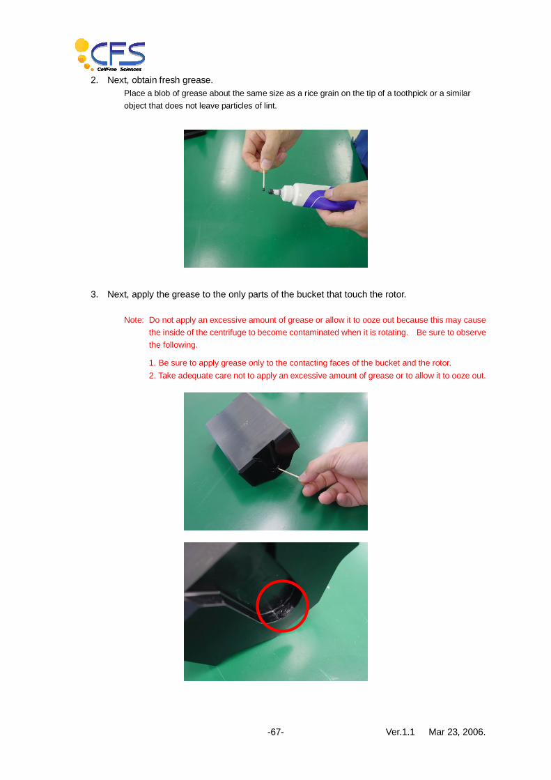
2. Next, obtain fresh grease. Place a blob of grease about the same size as a rice grain on the tip of a toothpick or a similar object that does not leave particles of lint.
3. Next, apply the grease to the only parts of the bucket that touch the rotor.
Note: Do not apply an excessive amount of grease or allow it to ooze out because this may cause
the inside of the centrifuge to become contaminated when it is rotating. Be sure to observe the following.
1. Be sure to apply grease only to the contacting faces of the bucket and the rotor. 2. Take adequate care not to apply an excessive amount of grease or to allow it to ooze out.

Ver.1.1 Mar 23, 2006. -68-
4. Return the bucket to its initial position, and slowly rock the bucket so that the grease becomes smeared over the entire contacting faces.
Note: If you press the bucket while rocking it, the rotary shaft of the centrifuge may bend, so do not
apply a load to the bucket when smearing the grease over the contacting surfaces.
5. Completion of greasing.

Ver.1.1 Mar 23, 2006. -69-
■30. Index
Accessories ........................................................ 8
Basic output ..................................... 10, 32, 39, 40
Bilayer method...................................... 2, 3, 9, 23
Centrifugal adapter........................................ 7, 10
Centrifuge... 2, 3, 5, 6, 7, 10, 31, 34, 39, 40, 42, 51,
59, 64, 65, 66
Centrifuge home position stop ..................... 10, 39
Centrifuge positioning........................................ 32
Consumables................................................ 8, 12
Dispenser 1............................................. 6, 50, 51
Dispenser 2........................................... 39, 50, 51
Dispensing tip ..................................................... 3
Emergency stop ................................................ 63
Halt buzzer ... 34, 36, 37, 40, 41, 42, 43, 44, 45, 46,
47, 49, 50, 51, 52, 53, 54, 55, 61, 62, 63
Hand..................... 6, 31, 32, 39, 44, 49, 50, 51, 60
Incubator............... 6, 10, 12, 18, 19, 34, 39, 47, 57
Initialization... 10, 11, 31, 34, 35, 41, 42, 43, 44, 45,
46, 47
Main menu............................................ 32, 33, 35
Maintenance menu........................... 10, 32, 33, 38
Options........................................................... 8, 9
Parameter..... 11, 30, 32, 33, 37, 38, 41, 42, 43, 44,
45, 46, 47, 51, 52, 53, 54, 55, 56, 57, 58, 59, 60,
61, 62
Pause ..... 12, 34, 36, 37, 40, 41, 42, 43, 44, 45, 46,
47, 49, 50, 51, 52, 53, 54, 55, 61, 62
Preparation ................................ 10, 19, 32, 34, 35
Program menu ................ 11, 32, 33, 34, 35, 36, 63
Program status........................... 12, 32, 33, 35, 36
Protocol ................................................ 23, 26, 30
Reaction plate ................................................. 3, 7
Reagent tub ........................... 6, 10, 18, 19, 39, 47
Remover Up/Down setting ........................... 32, 41
Samples............................................................. 8
Samples processed ............................................ 3
Screening.......................................... 9, 13, 14, 15
Sensor monitor............................................ 32, 38
Setting up.................................................... 30, 31
Small ...................................................... 9, 16, 17
Startup screen ............................................. 32, 33
Supernatant ....................................................... 2
Supernatant removal ............ 10, 20, 34, 39, 41, 60
Supernatant removal unit ................................. 2, 7
Synthesizing method ....................................... 2, 3
Template ..................................................... 2, 3, 7
Tip ....................................... 3, 6, 7, 37, 46, 47, 52
Waste box........................................................ 10
Waste gate......................................................... 7
Water absorption pad....................................... 6, 7
Workbench................................................ 4, 5, 10
■31. Amendment History
Edition Date of amendment Remarks
First edition June 5, 2004 First edition
Second edition August 31, 2004 Second edition
Third edition August 22, 2005 Third edition
Fourth edition October 7, 2005 Fourth edition
Ver.1.1 Mar 23, 2006. -70-
For inquiries concerning this operation manual, and also the machine, reagents and consumables, please contact one of the following.
Sales Department Cell-free Science Co., Ltd.
Tel: +81-45-500-2119 Fax: +81-45-500-2117
Head Office
No.201, Leading Venture Plaza 1, 75-Banchi, Ono-cho, Tsurumi-Ku,
Yokohama City, Kanagawa 230-0046, Japan
Tel: +81-45-500-2115
Fax: +81-45-500-2117
Matsuyama Branch VBL4F, Ehime University
No.3, Bunkyo-cho, Matsuyama City, Ehime 790-0826, Japan
Tel: +81-89-925-1088
Fax: +81-89-925-1088


