Original Article Journal of Intelligent Material Systems and Structures 24(13) 1647–1663 Ó The Author(s) 2013 Reprints and permissions: sagepub.co.uk/journalsPermissions.nav DOI: 10.1177/1045389X13483024 jim.sagepub.com Fully coupled electromechanical elastodynamic model for guided wave propagation analysis Luke Borkowski, Kuang Liu and Aditi Chattopadhyay Abstract Physics-based computational models play a key role in the study of wave propagation for structural health monitoring and thedevelopment of improved damage detection methodologies. Due to the complex nature of guided waves, accu- rate and efficient computation tools are necessary to investigate the mechanisms responsible for dispersion, coupling, and interaction with damage. In this article, a fully coupled electromechanical elastodynamic model for wave propagation in a heterogeneous, anisotropic material system is developed. The final framework provides the full three-dimensional displacement and electrical potential fields for arbitrary plate and transducer geometries and excitation waveform and frequency. The model is validated theoretically and proven computationally efficient. Studies are performed with surface- bonded piezoelectric sensors to gain insight into the physics of experimental techniques used for structural health monitoring. Collocated actuation of the fundamental Lamb wave modes is modeled over a range of frequencies to demonstrate mode tuning capabilities. The displacement of the sensing surface is compared to the piezoelectric sensor electric potential to investigate the relationship between plate displacement and sensor voltage output. Since many stud- ies, including the ones investigated in this article, are difficult to perform experimentally, the developed model provides a valuable tool for the improvement of structural health monitoring techniques. Keywords Structural health monitoring, piezoelectric, actuator, lamb wave, sensor Introduction Among the various techniques used for structural health monitoring (SHM) of aerospace, civil, and mechanical structures, guided wave (GW)–based tech- niques have been proven most effective because of their wide array of applications and sensitivity to multiple types of damage (Andrews et al., 2008; Giurgiutiu, 2008; Raghavan and Cesnik, 2007). One of the most promising GW-based approaches for damage detection in these structures is Lamb wave–based SHM tech- niques (Alleyne and Cawley, 1992; Giurgiutiu, 2008; Jha and Watkins, 2009; Staszewski et al., 1997), which typically involve exciting the structure with ultrasonic stress waves, collecting its structural response, and then processing this response for detection and in situ char- acterization of damage. Lamb waves have the ability to travel long distances in plate-like structures; therefore, SHM techniques utilizing Lamb wave analysis have the potential to monitor large areas with few actuators and sensors (Giurgiutiu, 2008). The abundance of struc- tures, in particular aerospace structural components, whose mechanical behavior resembles that of thin plates or shells, also contributes to the vast application of this technique. To excite the structure with a Lamb wave, piezoelectric transducers are often used due to their various advantages, particularly the ability to serve as both an actuator and sensor (Diaz and Soutis, 2000; Giurgiutiu, 2008; Guo and Cawley, 1993). Lamb wave techniques have been used by many researchers for damage detection in both metallic and composite structures. However, most of these methods are data driven (Liu et al., 2010, 2011; Soni et al., 2009). Conducting an experiment for every sensor loca- tion, waveform type and frequency, and damage type and severity can be time-consuming and expensive. The use of hybrid sensing approaches that combine experi- mental data with results from a physics-based model School for Engineering of Matter, Transport and Energy, Arizona State University, Tempe, AZ, USA Corresponding author: Luke Borkowski, School for Engineering of Matter, Transport and Energy, Arizona State University, P.O. Box 876106, Tempe, AZ 85287-6106, USA. Email: [email protected]
Transcript
Original Article
Journal of Intelligent Material Systemsand Structures24(13) 1647–1663� The Author(s) 2013Reprints and permissions:sagepub.co.uk/journalsPermissions.navDOI: 10.1177/1045389X13483024jim.sagepub.com
Fully coupled electromechanicalelastodynamic model for guided wavepropagation analysis
Luke Borkowski, Kuang Liu and Aditi Chattopadhyay
AbstractPhysics-based computational models play a key role in the study of wave propagation for structural health monitoringand the development of improved damage detection methodologies. Due to the complex nature of guided waves, accu-rate and efficient computation tools are necessary to investigate the mechanisms responsible for dispersion, coupling,and interaction with damage. In this article, a fully coupled electromechanical elastodynamic model for wave propagationin a heterogeneous, anisotropic material system is developed. The final framework provides the full three-dimensionaldisplacement and electrical potential fields for arbitrary plate and transducer geometries and excitation waveform andfrequency. The model is validated theoretically and proven computationally efficient. Studies are performed with surface-bonded piezoelectric sensors to gain insight into the physics of experimental techniques used for structural healthmonitoring. Collocated actuation of the fundamental Lamb wave modes is modeled over a range of frequencies todemonstrate mode tuning capabilities. The displacement of the sensing surface is compared to the piezoelectric sensorelectric potential to investigate the relationship between plate displacement and sensor voltage output. Since many stud-ies, including the ones investigated in this article, are difficult to perform experimentally, the developed model provides avaluable tool for the improvement of structural health monitoring techniques.
KeywordsStructural health monitoring, piezoelectric, actuator, lamb wave, sensor
Introduction
Among the various techniques used for structuralhealth monitoring (SHM) of aerospace, civil, andmechanical structures, guided wave (GW)–based tech-niques have been proven most effective because of theirwide array of applications and sensitivity to multipletypes of damage (Andrews et al., 2008; Giurgiutiu,2008; Raghavan and Cesnik, 2007). One of the mostpromising GW-based approaches for damage detectionin these structures is Lamb wave–based SHM tech-niques (Alleyne and Cawley, 1992; Giurgiutiu, 2008;Jha and Watkins, 2009; Staszewski et al., 1997), whichtypically involve exciting the structure with ultrasonicstress waves, collecting its structural response, and thenprocessing this response for detection and in situ char-acterization of damage. Lamb waves have the ability totravel long distances in plate-like structures; therefore,SHM techniques utilizing Lamb wave analysis have thepotential to monitor large areas with few actuators andsensors (Giurgiutiu, 2008). The abundance of struc-tures, in particular aerospace structural components,whose mechanical behavior resembles that of thin
plates or shells, also contributes to the vast applicationof this technique. To excite the structure with a Lambwave, piezoelectric transducers are often used due totheir various advantages, particularly the ability toserve as both an actuator and sensor (Diaz and Soutis,2000; Giurgiutiu, 2008; Guo and Cawley, 1993).
Lamb wave techniques have been used by manyresearchers for damage detection in both metallic andcomposite structures. However, most of these methodsare data driven (Liu et al., 2010, 2011; Soni et al.,2009). Conducting an experiment for every sensor loca-tion, waveform type and frequency, and damage typeand severity can be time-consuming and expensive. Theuse of hybrid sensing approaches that combine experi-mental data with results from a physics-based model
School for Engineering of Matter, Transport and Energy, Arizona State
University, Tempe, AZ, USA
Corresponding author:
Luke Borkowski, School for Engineering of Matter, Transport and Energy,
Arizona State University, P.O. Box 876106, Tempe, AZ 85287-6106, USA.
(referred to as virtual sensing) has been found to bemore effective in damage detection of complex aero-space structures (Chattopadhyay et al., 2009). Thesemodels provide insight into the damage mechanism,allowing for further optimization of SHM techniques.
The complexity of Lamb waves that are excited andsensed using piezoelectric actuators and sensors forSHM arises from their dispersive nature, existence of atleast two modes at any given frequency of excitation,electromechanical coupling due to the piezoelectricphenomenon, interaction with damage and materialdiscontinuities at various length scales, and the three-dimensional (3D) nature of the problem. It is advanta-geous, therefore, to have computational models tostudy the physics of wave propagation, which can aidin the development of accurate damage detection meth-odologies. Models for wave propagation also provide ameans to interpret the results obtained from experi-ments since the full displacement, stress, and strainfields can be studied as opposed to only the sensor sig-nal in the case of experiments.
Due to limitations associated with analytical wavepropagation models for aerospace structures, such asthe difficulty involved in modeling complex geometriesand material architectures and accounting for damage,numerical models are employed to solve the elastody-namic wave equation for the desired geometry, bound-ary conditions, actuation signals, and materialproperties. Numerous numerical techniques exist formodeling elastic wave propagation, such as finite ele-ment method (FEM; Koshiba et al., 1984; Talbot andPrzemieniecki, 1976; Zienkiewicz, 1989), finite strip ele-ments (Cheung, 1976; Liu and Achenbach, 1995; Liuet al., 1999), boundary element method (Cho and Rose,1996; Yamawaki and Saito, 1992), spectral elementmethods (Fornberg, 1998; Hu et al., 2007; Krawczukand Ostachowicz, 2001), and local interaction simula-tion approach (LISA)/sharp interface model (SIM)(Delsanto et al., 1992, 1994, 1997).
In materials with the presence of damage or othermaterial discontinuities (Agostini et al., 2003; Lee andStaszewski, 2007), LISA/SIM has proven to be an effec-tive, accurate, and computationally efficient modelingtechnique for wave propagation. One of the mainadvantages of LISA/SIM is its ability to model wavepropagation across sharp material property interfaceswithout incurring significant numerical error caused bythe smearing of material properties across cell interfaces(Delsanto et al., 1992, 1994, 1997). Lee and Staszewski(2007) modeled Lamb wave–based damage detection inmetallic specimens using LISA/SIM. Sundararaman(2007) extended the technique to include adaptive gridspacing for higher spatial resolution in regions of geo-metric complexity. Most Lamb wave studies using thistechnique are carried out on two-dimensional (2D) geo-metries for the reason of computational efficiency (Leeand Staszewski, 2007). Since Lamb waves only exist in
3D-bounded media, the 2D models require the Lambwave group and phase velocities to be provided a priorifor the in-plane simulation while the wave propagationin the through-thickness direction is modeled sepa-rately. Modeling the 3D problem in this 2D fashion lim-its the usefulness and accuracy of the model. A full 3Dmodel is required to account for the coupling betweenthe separate Lamb wave modes and to represent themode conversions and reflections caused by boundaries,damage, or other material discontinuities. While LISA/SIM has been proven to be an effective tool for GW-based SHM, Raghavan and Cesnik (2007) asserted thatthe application of this technique has been limited due tothe lack of a fully coupled electromechanical elastody-namic formulation to account for Lamb wave excita-tion and sensing.
Modeling of GW excitation and sensing is crucial towave propagation simulation techniques because of thecomplex coupling between the electrical excitation ofthe piezoelectric actuator, the subsequent mechanicalresponse of the actuator and structure, and finally themechanical and electrical responses of the sensor.Previous work focused on modeling the excitation ofGWs has primarily been based on the theory of elasti-city; it has utilized the ‘‘plane-strain’’ assumption andhas been limited to 2D (Ditri and Rose, 1994; Viktorov,1967). Extensions of the elasticity theory–basedapproaches to 3D have used impulse point body force(Santosa and Pao, 1989) and generic surface pointsources (Wilcox, 2004) to model the GW excitation.Relatively little work, however, has been done on mod-eling structurally integrated piezoelectric actuators withfinite dimensions. Moulin et al. (2000) modeled asurface-mounted lead zirconate titanate (PZT) using acoupled FEM–normal mode expansion method. Otherresearchers have also utilized the built-in piezoelectricelements in commercial finite element packages (Soniet al., 2009) to model actuators and sensors for SHMapplications. Mindlin plate theory incorporating trans-verse shear and rotary inertia effects was used by otherresearchers to model the GW excitation as causingbending moments along the actuator edge (Rose andWang, 2004; Veidt et al., 2001). One major disadvan-tage of using Mindlin plate theory is that it can onlymodel approximately the zero-order antisymmetricLamb wave mode and is only valid at low frequencieswhere no additional higher order antisymmetric modesare excited in the plate.
Giurgiutiu et al. (2003) modeled an infinitely widepiezoelectric transducer to study the excitation ofLamb waves in an isotropic plate. They solved for thedisplacement and strain fields by first reducing the 3Delasticity problem to 2D using the Fourier integral the-orem and then coming to a solution through inversionusing residue theory. Raghavan and Cesnik (2005)developed an analytical modeling technique using 3Delasticity theory and the Fourier integral theorem to
1648 Journal of Intelligent Material Systems and Structures 24(13)
model actuators and sensors of finite dimensions. Thisapproach was validated experimentally and numericallyfor the cases under investigation in the article.However, the assumption made in the formulation ofthe analytical approach introduced in Raghavan andCesnik (2005) limits its application to Lamb wave anal-ysis in infinite plates without considering the effect ofthe actuator and sensor on structural dynamics andwave behavior since the actuation is modeled as caus-ing an in-plane traction of uniform magnitude onlyalong its perimeter in the direction normal to the freeedge of the plate surface. In addition, the platethrough-thickness displacement is not provided withthis approach.
In the current article, a fully coupled electromechani-cal elastodynamic model for wave propagation in a het-erogeneous, anisotropic material system is developed.The objective of developing this novel modeling schemeis to accurately and efficiently study the physics of GWpropagation for the purpose of SHM, and, in turn, easethe monitoring strategy used for damage detection withGWs. The final set of equations provides the full 3Ddisplacement and electrical potential fields for arbitraryplate and transducer geometries and excitation wave-form and frequency. The model framework is based onthat developed by Delsanto et al. (1997) for an ortho-tropic material, but is extended to include piezoelectriccoupling and explicit consideration of the piezoelectricactuators and sensors for an anisotropic material sys-tem. The model is validated theoretically by comparingthe simulated wave speed to that predicted by Lambwave theory over a wide range of frequency–thicknessproducts. Various studies, some of which are difficultto conduct experimentally, are investigated for the gov-erning physics of GW analysis for SHM. These studiesinclude investigating the effect of actuation types onsensor signals, relative sensor voltage of Lamb wavemodes excited with collocated actuators, and the rela-tionship between the displacement components belowthe piezoelectric sensor with the sensor voltage.
3D electromechanical coupledelastodynamic model framework
This section outlines the derivation of a set of incre-mental equations for the solution of a 3D fully general-ized, fully coupled electromechanical elastodynamicwave propagation model for a heterogeneous, anisotro-pic material system. The final set of equations will pro-vide the evolution of the time-varying displacementand electric potential fields for an arbitrary geometryand actuation waveform. This formulation solves themechanical equations of motion as an initial valueproblem and Maxwell’s equation as a boundary valueproblem at each time step.
Governing equations and discretization
In this approach, the spatial domain is discretized inthe x, y, and z directions into a cuboidal grid withdimensions Dx, Dy, and Dz, respectively, as shown inFigure 1. The material properties of each cell aredefined at the lower left front corner of the cell, mean-ing an element with its center at location(a+Dx=2,b+Dy=2, g +Dz=2) will have its mechani-cal and physical properties defined at (a,b, g). Whilethe material properties are constant within each cell,they are allowed to vary across cells. The incorporationof SIM into the LISA framework allows for the accu-rate simulation of wave propagation across sharp mate-rial boundaries since the material properties are notsmeared across cell interfaces. Additional points aredefined in the grid, denoted by a star and a cross inFigure 1, at infinitesimal distances d and i from thenodal points and the interface in order to enforce conti-nuity of displacement at the nodes and traction acrossthe interface. The distances d and i are exaggerated inFigure 1 for clarity.
The governing equations for a linear piezoelectriccontinuum can be found in ANSI/IEEE (1987). For alinear elastic piezoelectric material, the constitutiveequation that governs the interaction of the elastic andelectric fields can be written as
sij =Cijklekl � ekijEk ð1Þ
where sij, Cijkl, ekl, ekij, and Ek are the second-orderstress tensor, fourth-order stiffness tensor, second-orderstrain tensor, third-order piezoelectric tensor, and first-order electric field tensor, respectively. In addition, theelectric displacement vector can be expressed in termsof the strain and electric field in the form
Figure 1. Definition of grid and supplemental points.
Borkowski et al. 1649
Di = eijkejk + kijEj ð2Þ
where Di is the first-order electric displacement tensorand kij is the second-order dielectric tensor.
The components of the small strain tensor ekl areexpressed in terms of the displacement components ukusing the strain–displacement relation
ekl =1
2uk, l + ul, kð Þ ð3Þ
and the components of the electric field Ei are obtainedfrom the electric potential fi via
Ei = � f, i ð4Þ
Using the strain–displacement relation (equation(3)), definition of electric field (equation (4)), and thesymmetry of the stiffness tensor, equations (1) and (2)can be expressed in terms of displacement and electricpotential as
sij =Cijkluk, l + ekijf, k ð5Þ
and
Di = eijkuj, k � kijf, j ð6Þ
In an elastic medium, force equilibrium is enforcedthrough the elastodynamic wave equation in the form
Cijkluk, jl + ekijf, kj = r€ui ð7Þ
It should be noted that viscoelasticity was notincluded in this article since this has been investigatedby previous researchers, such as Sundararaman (2007).
In the absence of volume charges, Maxwell’s equation
r �D= 0 ð8Þ
must be satisfied, which requires
eijkuj, ki � kijf, ji = 0 ð9Þ
A central difference scheme is used to approximatethe second-order derivatives of the displacement andelectrical potential at points defined at(a+ ad,b+ bd, g + cd) in the cuboidal grid in termsof their first-order derivatives. Here, a, b, and c repre-sent neighboring nodes and have the value of 61, 61,and 61, respectively, and d represents a small distanceaway from the node. Some of the expressions for thesecond-order differential equations are supplied herefor clarity
ua+ ad,b+ bd,g + cdk, 11 =
ua+ a=2,b, g
k, 1 � ua+ ad,b+ bd, g + cdk, 1
aDx=2
ð10Þ
ua+ ad,b+ bd,g + cdk, 12 =
ua+ a,b+ b=2, g
k, 2 � ua,b+ b=2, g
k, 2
aDxð11Þ
fa+ ad,b+ bd, g + cd, 11 =
fa+ a=2,b, g
, 1 � fa+ ad,b+ bd, g + cd, 1
aDx=2
ð12Þ
fa+ ad,b+ bd, g + cd, 12 =
fa+ a,b+ b=2, g
, 2 � fa,b+ b=2, g
, 2
aDxð13Þ
Similarly, the first-order derivatives of displacementand electric potential at points (a+ a=2,b, g),(a,b+ b=2, g), and (a,b, g + c=2) are also expressedusing finite difference. For brevity, these expressionsare not included in this article.
Next, continuity of displacement and electric poten-tial will be enforced at additional points defined at asmall distance from the grid points. A very small dis-tance, denoted by i, will be defined as
i= dx, x� 1 ð14Þ
Since the procedure for enforcing continuity of thefirst derivative of displacement is similar to that ofDelsanto et al. (1997), it is not repeated in this article.However, the continuity of the first derivative of elec-tric potential results in
fa+ ai,b+ bd, g + cd, 1 =f
a+ ad,b+ bd, g + cd, 1 ð15Þ
fa+ ad,b+ bi, g + cd, 1 =
fa+ a,b, g � fa,b, g
aDxð16Þ
fa+ ad,b+ bd, g + ci, 1 =
fa+ a,b, g � fa,b, g
aDxð17Þ
fa+ ai,b+ bd, g + cd, 2 =
fa,b+ b, g � fa,b, g
bDyð18Þ
fa+ ad,b+ bi, g + cd, 2 =f
a+ ad,b+ bd, g + cd, 2 ð19Þ
fa+ ad,b+ bd, g + ci, 2 =
fa,b+ b, g � fa,b, g
bDyð20Þ
fa+ ai,b+ bd, g + cd, 3 =
fa,b, g + c � fa,b,g
cDzð21Þ
fa+ ad,b+ bi, g + cd, 3 =
fa,b, g + c � fa,b,g
cDzð22Þ
fa+ ad,b+ bd, g + ci, 3 =f
a+ ad,b+ bd, g + cd, 3 ð23Þ
The expressions for the first-order derivatives inequations (15), (19), and (23), in addition to their dis-placement counterparts, remain unknown. To solve forequilibrium and Maxwell’s equation, continuity of trac-tions and electric displacement across the element inter-faces are enforced. This will allow for the unknownfirst-order derivatives to be eliminated.
1650 Journal of Intelligent Material Systems and Structures 24(13)
Enforcement of elastodynamic equilibrium andcontinuity of traction
Evaluating the elastodynamic equilibrium at the points(a+ ad,b+ bd, g + cd) can be expressed as
Ca+ ad,b+ bd,g + cdijkl u
a+ ad,b+ bd, g + cdk, lj
+ ea+ ad,b+ bd, g + cdlij f
a+ ad,b+ bd, g + cd, lj
= ra+ ad,b+ bd, g + cd€ua+ ad,b+ bd, g + cdi
ð24Þ
for a, b, and c = 61.The stress tensor at points near the nodes can be
expressed as
sa+ ad,b+ bd, g + cdij
=Ca+ ad,b+ bd, g + cdijkl u
a+ ad,b+ bd, g + cdk, l
+ ea+ ad,b+ bd,g + cdlij f
a+ ad,b+ bd, g + cd, l
ð25Þ
for a, b, and c = 61.Next, traction continuity is imposed across the cell
interfaces at points near the nodes while recalling thatthe material properties (e.g. stiffness tensor, density,piezoelectric tensor, and dielectric tensor) are constantin each cell, for example
Ca+ i,b+ d, g + dijkl =C
a+ d,b+ i, g + dijkl
=Ca+ d,b+ d, g + iijkl =C
a+ d,b+ d, g + dijkl =C
a,b, gijkl
ð26Þ
Since the cell faces are orthogonal and aligned, thetractions can be expressed directly as the stress tensor.The vector equations can be expressed in compactedform as
sa�i,b+ bd, g + cdi1 =s
a+ i,b+ bd,g + cdi1 ð27Þ
sa+ ad,b�i, g + cdi2 =s
a+ ad,b+ i,g + cdi2 ð28Þ
sa+ ad,b+ bd, g�ii3 =s
a+ d,b+ bd, g + ii3 ð29Þ
for a, b, and c = 61.
Final expressions for nodal mechanical displacement
After substituting the expressions for stress into equa-tions (27) to (29), replacing the first-order and second-order spatial derivatives with their respective finite dif-ference expressions in equations (24) and (25), andsumming over a, b, and c, the unevaluated first-orderderivatives can be eliminated through a linear combina-tion of the traction continuity and equilibrium equa-tions. The time derivatives of the displacement are thenexpanded using finite difference, and the final expres-sion for the nodal displacement at time t + Dt isachieved, as presented in equations (30) and (32) to(34). The solution of displacement at any point at timet + Dt, solved using forward integration, is a function
of the material properties of the surrounding elementsand the displacement and electric potential of the sur-rounding nodes at time t and t 2 Dt
ua,b, g, t + 1i = 2u
a,b, g, ti � u
a,b, g, t�1i
+dt2
8�r
Xa, b, c=61
f + g + hð Þ ð30Þ
where
�r =1
8
Xa, b, c=61
rs ð31Þ
and
f = 2fx
Dx2+
fy
Dy2+
fz
Dz2
� �
fx =Csi1k1 u
a+ a,b,gk � u
a,b,gk
� �+ es
1i1 fa+ a,b,g �fa,b,g� �
fy =Csi2k2 u
a,b+b,gk � u
a,b,gk
� �+ es
2i2 fa,b+b,g �fa,b,g� �
fz =Csi3k3 u
a,b,g+ ck � u
a,b,gk
� �+ es
3i3 fa,b,g+ c � fa,b,g� �
ð32Þ
and
g=2gxy
abDxDy+
gxz
acDxDz+
gyx
abDxDy+
gyz
bcDyDz
�
+gzx
acDxDz+
gzy
bcDyDz
�
gxy=Csi1k2 u
a,b+b,gk � u
a,b,gk
� �+es
2i1 fa,b+b,g�fa,b,g� �
gxz=Csi1k3 u
a,b,g+ck � u
a,b,gk
� �+es
3i1 fa,b,g+c�fa,b,g� �
gyx=Csi2k1 u
a+a,b,gk � u
a,b,gk
� �+es
1i2 fa+a,b,g�fa,b,g� �
gyz=Csi2k3 u
a,b,g+ck � u
a,b,gk
� �+es
3i2 fa,b,g+c�fa,b,g� �
gzx=Csi3k1 u
a+a,b,gk � u
a,b,gk
� �+es
1i3 fa+a,b,g�fa,b,g� �
gzy=Csi3k2 u
a,b+b,gk � u
a,b,gk
� �+es
2i3 fa,b+b,g�fa,b,g� �
ð33Þ
and
h=hxy
abDxDy+
hxz
acDxDz+
hyz
bcDyDz
hxy = Csi1k2 +Cs
i2k1
� �u
a+ a,b+ b, gk � u
a+ a,b, gk � u
a,b+ b, gk + u
a,b, gk
� �+
es1i2 + es
2i1
� �fa+ a,b+ b, g � fa+ a,b, g � fa,b+ b, g +fa,b, g� �
hxz = Csi1k3 +Cs
i3k1
� �u
a+ a,b, g + ck � u
a+ a,b, gk � u
a,b, g + ck + u
a,b, gk
� �+
es1i3 + es
3i1
� �fa+ a,b, g + c � fa+ a,b, g � fa,b, g + c +fa,b, g� �
hyz = Csi2k3 +Cs
i3k2
� �u
a,b+ b, g + ck � u
a,b+ b, gk � u
a,b, g + ck + u
a,b, gk
� �+
es2i3 + es
3i2
� �fa,b+ b, g + c � fa,b+ b, g � fa,b, g + c +fa,b, g� �
ð34Þ
Borkowski et al. 1651
where superscript s denotes the point (a+ ad,b+ bd, g + cd).
Enforcement of Maxwell’s equation and continuity ofelectric displacement
A similar approach is followed to achieve an expressionfor the electric potential at time t. First, Maxwell’sequation is enforced at every point (a+ ad,b+ bd, g + cd) as
ea+ ad,b+ bd, g + cdijk u
a+ ad,b+ bd, g + cdj, ki
� ka+ ad,b+ bd,g + cdij f
a+ ad,b+ bd, g + cd, ji = 0
ð35Þ
for a, b, and c = 61.Next, the continuity of the normal electric displace-
ments is enforced at infinitesimal distances from theinterface, which will result in the following equations
Da+ i,b+ bd, g + cd1 =D
a�i,b+ bd, g + cd1 ð36Þ
Da+ ad,b+ i, g + cd2 =D
a+ ad,b�i, g + cd2 ð37Þ
Da+ ad,b+ bd,g + i3 =D
a+ ad,b+ bd, g�i3 ð38Þ
for a, b, and c = 61.
Final expressions for nodal electrical potential
After substituting the expressions for electric displace-ment (equation (6) into equations (36) to (38)), repla-cing the first-order spatial derivatives with theirrespective finite difference expressions in equations (6)and (9), and summing over a, b, and c, the unevaluatedfirst-order derivatives can be eliminated through a lin-ear combination of the electric displacement continuityand Maxwell’s equation. After simplification, the finalexpression for the electric potential at time t is achieved,as seen in equations (39) to (42). The solution of electricpotential at any point at time t is a function of thematerial properties of the surrounding elements and thedisplacement and electric potential of the surroundingnodes at time t. Since the coupled equation for electricdisplacement at the point (a,b, g) at the current timestep is dependent on the electric potential of the nodessurrounding the point (a,b, g) at the current timestep, the solution of the boundary value problemrequires a linear algebra technique for the solution of aset of dependent equations. For this article, LU decom-position was utilized to solve for the electric potentialfor the reasons of computational accuracy andefficiency.
Xa, b, c=61
q+ r+ sð Þ= 0 ð39Þ
where
q= 2qx
Dx2+
qy
Dy2+
qz
Dz2
� �
qx = es1j1 u
a+ a,b, gj � u
a,b, gj
� �� ks
11 fa+ a,b, g � fa,b, g� �
qy = es2j2 u
a,b+ b, gj � u
a,b, gj
� �� ks
22 fa,b+ b, g � fa,b, g� �
qz = es3j3 u
a,b, g + cj � u
a,b, gj
� �� ks
33 fa,b, g + c � fa,b, g� �
ð40Þ
and
r = 2rxy
abDxDy+
rxz
acDxDz+
ryx
abDxDy+
ryz
bcDyDz
�
+rzx
acDxDz+
rzy
bcDyDz
�
rxy = es1j2 u
a,b+ b, gj � u
a,b, gj
� �� ks
12 fa,b+ b,g � fa,b,g� �
rxz = es1j3 u
a,b,g + cj � u
a,b,gj
� �� ks
13 fa,b, g + c � fa,b, g� �
ryx = es2j1 u
a+ a,b, gj � u
a,b, gj
� �� ks
21 fa+ a,b,g � fa,b,g� �
ryz = es2j3 u
a,b,g + cj � u
a,b,gj
� �� ks
23 fa,b, g + c � fa,b, g� �
rzx = es3j1 u
a+ a,b, gj � u
a,b, gj
� �� ks
31 fa+ a,b,g � fa,b,g� �
rzy = es3j2 u
a,b+ b, gj � u
a,b, gj
� �� ks
32 fa,b+ b,g � fa,b,g� �
ð41Þ
and
s=sxy
abDxDy+
sxz
acDxDz+
syz
bcDyDz
sxy = es1j2 + es
2j1
� �u
a+ a,b+ b,gj � u
a+ a,b,gj � u
a,b+ b,gj + u
a,b, gj
� ��
ks12 + ks
21
� �fa+ a,b+ b, g � fa+ a,b, g � fa,b+ b,g +fa,b,g� �
sxz = es1j3 + es
3j1
� �u
a+ a,b, g + cj � u
a+ a,b, gj � u
a,b, g + cj + u
a,b, gj
� ��
ks13 + ks
31
� �fa+ a,b, g + c � fa+ a,b, g � fa,b,g + c +fa,b, g� �
syz = es2j3 + es
3j2
� �u
a,b+ b, g + cj � u
a,b+ b, gj � u
a,b, g + cj + u
a,b, gj
� ��
ks23 + ks
32
� �fa,b+ b, g + c � fa,b+ b, g � fa,b,g + c +fa,b, g� �
ð42Þ
where superscript s denotes the point (a+ ad,b+ bd, g + cd).
Simulation results and discussion
Physical model development
A 247 3 247 3 4-mm aluminum plate with collocatedactuators and a single sensor was modeled for the stud-ies presented in this article. The actuators and sensorswere centered on the plate and separated by a distanceof 22 mm. The aluminum plate was modeled as a
1652 Journal of Intelligent Material Systems and Structures 24(13)
homogeneous, isotropic material with a density of 2780kg/m3, Young’s modulus of 70 GPa, and Poisson’sratio of 0.3. The orthotropic material properties of thePZT piezoelectric actuators and sensors are presentedin Table 1. A 5-cycle cosine tone burst signal was usedto excite the PZT actuators with a maximum electricpotential of 10 V.
Issues that must be considered when implementingthe current numerical framework for wave propagationmodeling are convergence, numerical dispersion, andpulse and amplitude distortions. Several factors con-tribute to these issues. Pulse distortion, for example,can be mitigated by satisfying the Courant–Friedrich–Lewy (CFL) number, equation (43)
where cmax is the maximum wave speed (i.e. longitudi-nal wave speed); Dt is the time step (i.e. samplingperiod); and Dx, Dy, and Dz are the grid spacings forthe cuboidal elements (Virieux, 1986). To preventamplitude distortion, the general criterion is to have atleast eight elements per minimum wavelength(Balasubramanyam et al., 1996). It is also commonlyadvised to avoid having more than 20 elements perminimum wavelength to avoid computational issuessuch as long run times and numerical error associatedwith the propagation of round-off error (Alleyne andCawley, 1991). The grid spacings (i.e. Dx, Dy, and Dz)and time step (i.e. Dt) for the studies presented in thisarticle were chosen to ensure convergence while mini-mizing numerical error and computational load. Thegrid spacings in the Dx, Dy, and Dz directions were heldat 1 mm while the time step was adjusted to satisfy theCFL criterion.
Theoretical validation
The fully coupled electromechanical model was vali-dated theoretically by modeling a 4-mm-thick alumi-num plate with collocated actuators and a single sensor,separated by a distance of 22 mm. The Lamb wave gov-erning equations (Lamb, 1917) are shown in equation(44) where the 61 exponent indicates the symmetricand antisymmetric modes, respectively. The governingequations were solved numerically using the techniqueoutlined in Rose (2004). The phase and group velocitiescan be then solved using equations (46) and (47)
tan bb=2ð Þtan ab=2ð Þ = � 4abk2
k2 � b2� �2
( )61
ð44Þ
where
a2 =v2
c2l
� k2, b2 =v2
c2t
� k2 ð45Þ
and v is the angular frequency, k is the wave number, clis the longitudinal wave speed, ct is the transverse wavespeed, and b is the plate thickness. The equations forthe Lamb wave group and phase velocities are
cp =v
kð46Þ
and
cg =dv
dkð47Þ
By utilizing collocated actuators, Lamb wave modescan be excited selectively, allowing for direct compari-son between the simulated results and the theoreticaldispersion curve for an aluminum plate over a range offrequencies commonly utilized for SHM. In addition tothe commonly used frequencies, additional simulationswere carried out to prove that the model can also accu-rately predict the Lamb wave group velocity at higherfrequency–thickness products. Giurgiutiu (2005) analy-tically determined that there is a limited frequencyrange in which the energy of the S0 mode is greaterthan that of the A0 mode. Because of this, collocatedactuators are necessary for comparing the simulated S0group velocity to that predicted with Lamb wave the-ory. Since the time-of-arrival of the A0 and S0 Lambwave modes is a common feature used in SHM damagedetection methodologies, wave propagation models forthis purpose must be able to accurately predict thewave speed of these zero-order modes. Figure 2 pre-sents a comparison between the simulated group veloci-ties (cg) versus the frequency–half thickness product(fb/2) with the theoretical A0 and S0 group velocities.The discrepancies between the simulated and theoreti-cal wave speed for some of the frequency–half thicknessproducts investigated can be attributed to the time lag
Table 1. PZT (APC 850) properties.
Elastic moduli (GPa) Poisson’s ratio Shear moduli (GPa)
in the sensor voltage or from grid dispersion caused byinsufficient spatial samples per wavelength.
The two fundamental Lamb wave modes (symmetricand antisymmetric) have distinct displacement signa-tures in the plane orthogonal to the propagation direc-tion of the wave. Lamb waves have the uniquecharacteristic of resembling a standing wave throughthe thickness and a traveling wave in plane. Figure 3demonstrates this phenomenon. For symmetric Lambwave modes, the out-of-plane displacement profile issymmetric while the in-plane displacement is antisym-metric with respect to the mid-plane of the plate. Forantisymmetric Lamb wave modes, the opposite is true.By plotting the out-of-plane and in-plane displacementsand the displacement vectors at each node for the A0
and S0 modes, the characteristic displacement profilesof each mode can be visualized and compared, asshown in Figures 4 to 7 for two simulation times(16.625 and 33.25 ms). It should be noted that the con-tours are not to scale as they have been rescaled toclearly demonstrate the through-thickness displacementprofile of Lamb waves.
Computational efficiency
The LISA/SIM solution methodology was formulatedto run in a parallel processing environment. Hence, thecomputational efficiency of the current model offerskey advantages over other wave propagation models. A247 3 247 3 4-mm aluminum plate with one actuatorand one sensor was modeled using the developed modeland the commercial finite element software Abaqus(2007). Both models were run in a parallel computingenvironment on eight Harpertown 2.66 GHz, 8 MB/Cache, 16 GB memory processors. Each model was runin double precision for 1000 iterations with a time stepof 9.5e28 s. The computation results are shown inTable 2. Although the number of elements required forthe current model (due to the surrounding air layers)was more than twice that required for the FEM model,the current model was significantly faster (.170 times)than the comparable FEM model. Using a time step of9.5e28, numerical instability occurred in the FEMmodel of the plate; a time step of 3e28 s was requiredto resolve the issue of numerical instability. In addition,
Figure 2. Theoretical validation of A0 and S0 Lamb mode group velocities.
Figure 3. Relative actuator voltage poling directions and resultant through-thickness displacement profile for collocatedpiezoelectric actuation for selective Lamb wave mode suppression.
1654 Journal of Intelligent Material Systems and Structures 24(13)
the FEM model under-predicted the theoretical wavespeed by 13.3% for a time step of 3e28 s while theresult using the current model was within 4.1% for atime step of 9.5e28 s.
Collocated actuators for selective Lamb wave modesuppression
Collocated piezoelectric actuators have been utilizedexperimentally to selectively suppress Lamb wave
modes for the purpose of SHM (Kim and Sohn, 2007).The suppression of one of the two fundamental Lambwave modes (symmetric or antisymmetric) is achievedby selectively poling the collocated piezoelectric actua-tors, indicated with the black arrows in Figure 3. InSHM, it is often desired to excite a wave with predomi-nately symmetric or antisymmetric behavior to facilitatetime-of-arrival calculation or to tailor the Lamb waveexcitation to the type and location of damage in thestructure. Although this phenomenon has been proventheoretically and successfully implemented
Figure 4. Through-thickness plots of (a) out-of-plane displacement, (b) in-plane displacement, and (c) vector field for A0 Lambwave mode at t = 16.625 ms for fb/2 = 300 kHz mm.
Figure 5. Through-thickness plots of (a) out-of-plane displacement, (b) in-plane displacement, and (c) vector field for S0 Lamb wavemode at t = 16.625 ms for fb/2 = 300 kHz mm.
Borkowski et al. 1655
experimentally (Kim and Sohn, 2007), it is difficult toreplicate experimentally. Slight variance in the relativeactuator placement or in the piezoelectric actuatorproperties can have a significant impact on the degreeof mode suppression. Numerical wave propagationmodels offer a valuable tool in investigating the physicsof this experimental technique. The ability to separatelymodel the fundamental Lamb wave modes is necessaryfor understanding the role each mode plays in the over-all propagation of the Lamb wave and its interactionwith damage and other features.
Giurgiutiu (2005) demonstrated the concept ofLamb wave mode tuning using a single actuator, whichinvolves exciting the structure with a frequency atwhich the A0 or S0 mode is most prevalent (i.e. largestrelative energy). This type of selective tuning is possiblebecause the energy of each mode varies with frequency.Although mode tuning using a single piezoelectricactuator has proven to be feasible, larger suppressionof the undesired mode can be achieved with collocatedactuators, as shown in Figure 3. Given the difficulty inimplementing this technique experimentally, numerical
Figure 6. Through-thickness plots of (a) out-of-plane displacement, (b) in-plane displacement, and (c) vector field for A0 Lambwave mode at t = 33.25 ms for fb/2 = 300 kHz mm.
Figure 7. Through-thickness plots of (a) out-of-plane displacement, (b) in-plane displacement, and (c) vector field for S0 Lamb wavemode at t = 33.25 ms for fb/2 = 300 kHz mm.
1656 Journal of Intelligent Material Systems and Structures 24(13)
models can be called to investigate the physics and pro-vide insight into the problem before experimentalimplementation occurs. For damage detection usingLamb waves, it is desirable to excite a mode with thelargest possible energy. Since the use of collocatedactuators cannot completely eliminate the undesiredmode, it is beneficial to know the frequency at whichthe maximum difference between the mode energiesoccurs. For homogeneous, isotropic specimens, an ana-lytical technique such as the one utilized by Kim andSohn (2007) and Giurgiutiu (2005) can predict the rela-tive mode energies; however, for specimens with com-plex heterogeneous architectures and anisotropy,numerical models such as the one presented in this arti-cle are required.
To demonstrate the concept, a 4-mm-thick alumi-num plate was modeled with collocated actuators and a
single sensor. Through modeling collocated actuatorsto selectively excite a single mode at various frequenciesand overlaying the sensor voltage results, the relativesensor energies can be compared, as shown in Figure8(a) to (d) for the frequency–half thickness products(fb/2) of 200, 300, 400, and 500 kHz mm, respectively.
Figure 8 demonstrates the dependence of Lambwave mode voltage amplitudes on excitation frequencyand the change in the relative amplitudes of the zero-order modes as a function of frequency–thickness prod-uct. At the frequency–half thickness product of 200kHz mm, the A0 mode is more prevalent (i.e. has ahigher relative energy) than the S0 mode. As thefrequency–thickness product increases, the relativeenergy of the S0 mode increases until it is the dominantmode, as shown in Figure 8(d) for a frequency–thickness product of 500 kHz mm. A systematic studysuch as the one presented in Figure 8 can be used toimprove experimental damage detection techniques andtailor excitation frequencies to best suit the type andlocation of damage in a specific material system.
Effect of actuation type
Before development of the fully coupled electromecha-nical theory for LISA/SIM, researchers wishing tomodel piezoelectric actuation (Lee and Staszewski,
Table 2. Computational efficiency comparison between FEMand current model.
Solver method Number of elements Wall clock time (s)
FEM 244,038 40,855Current model 567,009 230
FEM: finite element method.
Figure 8. Comparison of sensor voltage between symmetric and antisymmetric zero-order Lamb wave modes for fb/2 equal to (a)200, (b) 300, (c) 400, and (d) 500 kHz mm.
Borkowski et al. 1657
2007; Sundararaman, 2007) were forced to apply dis-placements to the ‘‘piezoelectric’’ nodes or the cellsbeneath the actuator. In a study on the excitation ofsurface-bonded piezoelectric transducers, Giurgiutiuet al. (2003) noted that the actuators typically used forSHM operated in a ‘‘pinching’’ fashion or by causing atraction tangent to the plate surface. Most researchersfound that application of an actuation in the form of adisplacement in the in-plane direction gave more accu-rate prediction of wave speeds. However, this type ofactuation does not take into consideration the complexpiezoelectric coupling occurring within the actuatorthat causes the application of traction to the plate sur-face as a result of the externally supplied voltage acrossthe actuator. To justify representing the piezoelectricactuation with applied displacement, an investigationinto the effects is necessary.
A study was conducted to investigate the effect ofand error incurred due to displacement actuation
compared to explicitly modeling the piezoelectricdevice. Three commonly used actuation types wereinvestigated: electrical actuation, displacement in they-direction actuation, and displacement in the z-direc-tion actuation, as shown in Figure 9. The sensor signalsfor the A0 and S0 Lamb wave modes received fromthree different actuations are shown in Figure 10(a)and (b), respectively, for fb/2 equal to 300 kHz mm. Itis evident from the plots that the time-of-arrival andwave speed of the displacement actuations vary signifi-cantly from that of the electrical actuation. Table 3 pre-sents a comparison of the simulated A0 and S0 wavespeeds (vs) for each of the three actuation types com-pared to the theoretical wave speed (vt) and the corre-sponding error. The theoretical wave speed wasobtained by numerically solving the characteristicLamb wave equations for the wave group velocity.
Analysis of the data in Table 3 reveals inconsistencyin wave speed that results from modeling the piezoelec-tric actuation as a displacement boundary condition. Inparticular, although the modeled wave speed for thez-direction displacement actuation is able to match thetheoretical A0 wave speed within 1.60%, its simulatedS0 wave speed is 39.21% below the theoretical wavespeed. Actuating the plate with a y-direction displace-ment results in a simulated wave speed that is greaterthan 20% above the theoretical A0 wave speed andgreater than 25% below the theoretical S0 wave speed.Due to the complex electromechanical coupling thatoccurs within a piezoelectric element, approximatingthe resultant displacement as unidirectional will pro-duce inaccurate and inconsistent model results.
Relationship between piezoelectric sensordisplacement and output voltage
An advantage to having an accurate numerical tool tosimulate the excitation, propagation, and sensing ofGW allows for investigating phenomena that is difficultto study in an experimental environment. A study was
Figure 9. Excitation of GW in plate for three differentactuation types: (a) displacement in the y direction, (b)displacement in the z direction, and (c) voltage actuation.GW: guided wave; PZT: lead zirconate titanate.
Figure 10. Sensor signal comparison for three different actuation types for fb/2 equal to 300 kHz mm: (a) sensor signal for A0
Lamb wave mode and (b) sensor signal for S0 Lamb wave mode.
1658 Journal of Intelligent Material Systems and Structures 24(13)
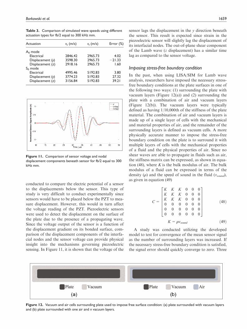
conducted to compare the electric potential of a sensorto the displacements below the sensor. This type ofstudy is very difficult to conduct experimentally sincesensors would have to be placed below the PZT to mea-sure displacement. However, this would in turn affectthe voltage reading of the PZT. Piezoelectric sensorswere used to detect the displacement on the surface ofthe plate due to the presence of a propagating wave.Since the voltage output of the sensor is a function ofthe displacement gradient on its bonded surface, com-parison of the displacement components of the interfa-cial nodes and the sensor voltage can provide physicalinsight into the mechanisms governing piezoelectricsensing. In Figure 11, it is shown that the voltage of the
sensor lags the displacement in the y direction beneaththe sensor. This result is expected since strain in thepiezoelectric sensor will slightly lag the displacement ofits interfacial nodes. The out-of-plane shear componentof the Lamb wave (z displacement) has a similar timelag as compared to the sensor voltage.
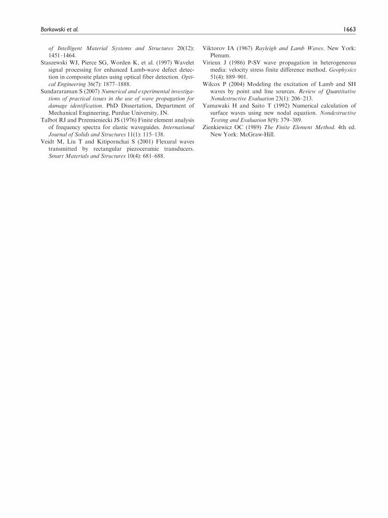
Imposing stress-free boundary condition
In the past, when using LISA/SIM for Lamb waveanalysis, researchers have imposed the necessary stress-free boundary conditions at the plate surfaces in one ofthe following two ways: (1) surrounding the plate withvacuum layers (Figure 12(a)) and (2) surrounding theplate with a combination of air and vacuum layers(Figure 12(b)). The vacuum layers were typicallydefined as having 1/10,000th of the stiffness of the platematerial. The combination of air and vacuum layers ismade up of a single layer of cells with the mechanicaland material properties of air, and the remainder of thesurrounding layers is defined as vacuum cells. A morephysically accurate manner to impose the stress-freeboundary condition on the plate is to surround it withmultiple layers of cells with the mechanical propertiesof a fluid and the physical properties of air. Since noshear waves are able to propagate in fluids such as air,the stiffness matrix can be expressed, as shown in equa-tion (48), where K is the bulk modulus of air. The bulkmodulus of a fluid can be expressed in terms of thedensity (r) and the speed of sound in the fluid (vsound),as given in equation (49)
C =
K K K 0 0 0
K K K 0 0 0
K K K 0 0 0
0 0 0 0 0 0
0 0 0 0 0 0
0 0 0 0 0 0
26666664
37777775
ð48Þ
K = rvsound ð49Þ
A study was conducted utilizing the developedmodel to test for convergence of the mean sensor signalas the number of surrounding layers was increased. Ifthe necessary stress-free boundary condition is satisfied,the signal error should quickly converge to zero. Three
Table 3. Comparison of simulated wave speeds using differentactuation types for fb/2 equal to 300 kHz mm.
Figure 11. Comparison of sensor voltage and nodaldisplacement components beneath sensor for fb/2 equal to 300kHz mm.
Figure 12. Vacuum and air cells surrounding plate used to impose free surface condition: (a) plate surrounded with vacuum layersand (b) plate surrounded with one air and n vacuum layers.
Borkowski et al. 1659
convergence studies were conducted for surroundinglayers with the properties of (1) vacuum, (2) combina-tion of air and vacuum, and (3) air with the mechanicalproperties of a fluid and are presented in Figure 13(a)to (c), respectively. The plots present the mean signalerror percentage as a function of the number of layers.The mean signal error is defined as the error betweenthe sensor signal at the current number of layers andthe sensor signal at the final number of layers investi-gated (i.e. 10 total layers for Cases 1 and 2 and 5 layersfor Case 3). Case 3 was only carried out to five layersbecause convergence was quickly achieved.
In Figure 13(a), it is evident that convergence is notreached as the number of vacuum layers increases. Thisis likely caused by numerical instability as a result ofthe physically inaccurate manner in which the free sur-face condition is imposed and the propagation andreflection of shear waves into the vacuum layers.Similarly, in Figure 13(b), it is evident that convergenceis not reached as the number of combined air andvacuum layers increases. This is also likely caused bynumerical instability as a result of the physically inac-curate manner in which the free surface condition isimposed. However, in Figure 13(c), it is evident thatconvergence is reached after approximately three
layers. Even with a single layer, very little error in thesensor signal is present. Numerical instability was neverfound to be present with this approach, even after 10layers.
By plotting the sensor signal from the simulationsusing air, vacuum, and air/vacuum cells surroundingthe medium to enforce the free surface boundary condi-tion, the numerical instability, denoted with the redoval, caused by the vacuum cells is evident. Thisinstability is not obvious in the sensor signal of the firstmode but becomes more pronounced as time pro-gresses. The instability witnessed in Figure 14 is notphysical, but rather caused by numerical instability ofthe solution. Imposing the stress-free boundary condi-tion in this way should be avoided since it does notprovide a physically accurate means in which to modelthe boundary of the plate and because the numericalinstability can cause significant error in the waveformfollowing the arrival of the S0 mode.
Conclusion
A fully coupled electromechanical elastodynamic modelfor wave propagation in a heterogeneous, anisotropicmaterial system was developed to investigate the
0%
20%
40%
60%
80%
100%
120%
0 2 4 6 8 10
Mea
n E
rror
Number of Vacuum Layers
0%
10%
20%
30%
40%
50%
60%
70%
80%
0 2 4 6 8 10
Mea
n E
rror
Number of Total Layers
0.000%
0.002%
0.004%
0.006%
0.008%
0.010%
0.012%
0.014%
0 1 2 3 4 5
Mea
n E
rror
Number of Air Layers
(a) (b)
(c)
Figure 13. Convergence of mean sensor signal using three kinds of boundary cells: (a) mean signal error versus number of vacuumlayers surrounding plate, (b) mean signal error versus number of air + vacuum layers surrounding plate, and (c) mean signal errorversus number of air layers surrounding plate.
1660 Journal of Intelligent Material Systems and Structures 24(13)
physics of wave propagation, in particular Lamb wavepropagation for the purpose of SHM. The model,derived using the LISA/SIM solution methodology,provides the capability of incorporating piezoelectricelements into a modeling scheme that has been previ-ously proven to be a valuable tool for GW-based dam-age detection in isotropic and composite structures ofarbitrary geometries and material architectures. Thedeveloped model was validated theoretically against thedispersion curve of an aluminum plate and provencapable of accurately simulating the group velocity ofthe A0 and S0 Lamb wave modes over a large range offrequency–thickness products. The through-thicknesscontour and velocity vector plots also verify that thesimulated Lamb wave out-of-plane and in-plane displa-cements match with the theoretical displacement pro-files. Beside its accuracy in predicting wave speeds, thedeveloped model was shown to be computationally effi-cient compared to finite element. Collocated actuatorswere modeled, and the physics of Lamb wave modesuppression was investigated, including the relativeenergy of the modes as a function of frequency. Theeffect of actuation type was studied to determine theresults from applying an equivalent displacementboundary condition on the actuator nodes to excite aGW instead of an electric potential across a piezoelec-tric element. It was found that inconsistent wave speedresults occurred with displacement boundary condition
actuation. A study comparing the piezoelectric sensorvoltage to the displacement of the interface nodes wasconducted, and it was found that there exists a time lagbetween the in-plane nodal displacement and the sensorvoltage. The developed model resulted in an accurateand efficient means to study the physics of GW propa-gation for SHM and assist in the development of SHMmonitoring strategies.
Acknowledgement
The authors thank Dr. David Stargel, Technical Monitor, forthe support of this work.
Funding
This study was supported in part by the National ScienceFoundation Graduate Research Fellowship under grant num-ber 2011124478 and the MURI Program, Air Force Office ofScientific Research, grant number FA9550-06-1-0309.
References
Abaqus (2007) Version 6.7, Abaqus/CAE and Abaqus/Explicit.
Providence, RI: SIMULIA World Headquarters.
Agostini V, Delsanto PP, Genesio I, et al. (2003) Simulation
of Lamb wave propagation for the characterization of
complex structures. IEEE Transactions on Ultrasonics,
Ferroelectrics and Frequency Control 50(4): 441–448.
Figure 14. Sensor signal comparison for three different boundary cells for fb/2 equal to 500 kHz mm: (a) sensor signal for 10 airlayers and 10 vacuum layers, (b) sensor signal for 10 air layers and 1 air + 9 vacuum layers, and (c) sensor signal for 10 vacuumlayers and 1 air + 9 vacuum layers.
Borkowski et al. 1661
Alleyne DN and Cawley P (1991) A two-dimensional Fouriertransform method for the measurement of propagating
multimode signals. Journal of the Acoustical Society of
America 89(3): 1159–1168.Alleyne DN and Cawley P (1992) The interaction of Lamb
waves with defects. IEEE Transactions on Ultrasonics, Fer-
roelectrics and Frequency Control 39(3): 381–397.Andrews JP, Palazotto AN, DeSimio MP, et al. (2008) Lamb
wave propagation in varying isothermal environments.Structural Health Monitoring 7(3): 265–270.
ANSI/IEEE (1987) Standard 176, Piezoelectricity. New York:
IEEE.Balasubramanyam R, Quinney D, Challis RE, et al. (1996) A
finite-difference simulation of ultrasonic Lamb waves inmetal sheets with experimental verification. Journal of Phy-
sics D: Applied Physics 29(1): 147–155.Chattopadhyay A, Peralta P, Papandreou-Suppappola A, et
al. (2009) A multidisciplinary approach to structural health
monitoring and damage prognosis of aerospace hotspots.Journal of Royal Aeronautical Society 113(1150): 799–810.
Cheung YK (1976) Finite Strip Method in Structural Analysis.
Oxford: Pergamon.Cho Y and Rose JL (1996) A boundary element solution for
mode conversion study of the edge reflection of Lamb
waves. Journal of the Acoustical Society of America 99(4):2097–2109.
Delsanto PP, Schechter RS and Mignogna RB (1997) Con-
nection machine simulation of ultrasonics wave propaga-tion in materials III: three-dimensional case. Wave Motion
nection machine simulation of ultrasonics wave propaga-
tion in materials I: one-dimensional case. Wave Motion
16(1): 65–80.Diaz S and Soutis C (2000) Health monitoring of composites
using Lamb waves generated by piezoelectric devices. Plas-tics, Rubber and Composites 29(9): 475–481.
Ditri J and Rose JL (1994) Excitation of guided waves in gen-erally anisotropic layers using finite sources. Journal of
Applied Mechanics: Transactions of the ASME 61(2): 330–338.
Fornberg B (1998) A Practical Guide to Pseudospectral Meth-
ods. Cambridge: Cambridge University Press.Giurgiutiu V (2005) Tuned Lamb wave excitation and detec-
tion with piezoelectric wafer sensors for structural health
monitoring. Journal of Intelligent Material Systems and
Structures 16(4): 291–305.Giurgiutiu V (2008) Structural Health Monitoring with Piezo-
electric Wafer Active Sensors. Boston, MA: AcademicPress.
Giurgiutiu V, Bao J and Zhao W (2003) Piezoelectric waferactive sensor embedded ultrasonics in beams and plates.
Experimental Mechanics 43(4): 428–449.Guo N and Cawley P (1993) The interaction of Lamb waves
with delaminations in composite laminates. Journal of the
Acoustical Society of America 94(4): 2240–2246.Hu N, Fukunaga H, Kameyama M, et al. (2007) Analysis of
wave propagation in beams with transverse and lateral
cracks using a weakly formulated spectral method. Journalof Applied Mechanics: Transactions of the ASME 74(1):
119–127.Jha R and Watkins R (2009) Lamb wave based diagnostics of
composite plates using a modified time reversal method.
In: Proceedings of 17th AIAA/ASME/AHS adaptive struc-
tures conference, 4–7 May, Palm Springs, CA.Kim SB and Sohn H (2007) Instantaneous reference-free
crack detection based on polarization characteristics ofpiezoelectric materials. Smart Materials and Structures
16(6): 2375–2387.Koshiba M, Karakida S and Suzuki M (1984) Finite element
analysis of Lamb waves scattering in an elastic plate wave-guide. IEEE Transactions on Sonics and Ultrasonics 31(1):
18–25.Krawczuk M and Ostachowicz W (2001) Spectral finite element
and genetic algorithm for crack detection in cantilever rod.
In: Proceedings of 4th international conference on damage
assessment of structures, 25–28 June, Cardiff, UK.Lamb H (1917) On waves in an elastic plate. Proceedings of
the Royal Society A: Mathematical Physical and Engineer-
ing Sciences 93(648): 114–128.Lee BC and Staszewski WJ (2007) Lamb wave propagation
modelling for damage detection: II. Damage monitoring
strategy. Smart Materials and Structures 16(2): 260–274.Liu G and Achenbach JD (1995) Strip element method to
analyze wave scattering by cracks in anisotropic laminated
plates. Journal of Applied Mechanics: Transactions of the
ASME 62(3): 607–613.Liu Y, Kim SB, Chattopadhyay A, et al. (2011) Application
of system identification techniques to health monitoring ofon-orbit satellite boom structures. Journal of Spacecraft
and Rockets 48(4): 589–598.Liu Y, Mohanty S and Chattopadhyay A (2010) Condition
based structural health monitoring and prognosis of com-posite structures under uniaxial and biaxial loading. Jour-
nal of Nondestructive Evaluation 29(3): 181–188.Liu G, Xi Z, Lam KY, et al. (1999) A strip element method
for analysing wave scattering by a crack in an immersed
composite laminate. Journal of Applied Mechanics: Trans-
actions of the ASME 66(4): 898–903.Moulin E, Assaad J and Delebarre C (2000) Modeling of
Lamb waves generated by integrated transducers in com-posite plates using a coupled finite element–normal modesexpansion method. Journal of the Acoustical Society of
America 107(1): 87–94.Raghavan A and Cesnik CES (2005) Finite-dimensional
piezoelectric transducer modeling for guided wave based
structural health monitoring. Smart Materials and Struc-
tures 14(6): 1448–1461.Raghavan A and Cesnik CES (2007) Review of guided-wave
structural health monitoring. Shock and Vibration Digest
39(2): 91–116.Rose JL (2004) Ultrasonic Waves in Solid Media. Cambridge:
Cambridge University Press.Rose LRF and Wang CH (2004) Mindlin plate theory for
damage detection: source solutions. Journal of the Acousti-cal Society of America 116(1): 154–171.
Santosa F and Pao YH (1989) Transient axially asymmetric
response of an elastic plate. Wave Motion 11: 271–295.Soni S, Das S and Chattopadhyay A (2009) Simulation of
damage features in a lug joint using guided waves. Journal
1662 Journal of Intelligent Material Systems and Structures 24(13)
of Intelligent Material Systems and Structures 20(12):1451–1464.
Staszewski WJ, Pierce SG, Worden K, et al. (1997) Waveletsignal processing for enhanced Lamb-wave defect detec-tion in composite plates using optical fiber detection. Opti-
cal Engineering 36(7): 1877–1888.Sundararaman S (2007) Numerical and experimental investiga-
tions of practical issues in the use of wave propagation for
damage identification. PhD Dissertation, Department ofMechanical Engineering, Purdue University, IN.
Talbot RJ and Przemieniecki JS (1976) Finite element analysisof frequency spectra for elastic waveguides. InternationalJournal of Solids and Structures 11(1): 115–138.
Veidt M, Liu T and Kitipornchai S (2001) Flexural wavestransmitted by rectangular piezoceramic transducers.Smart Materials and Structures 10(4): 681–688.
Viktorov IA (1967) Rayleigh and Lamb Waves. New York:Plenum.


![Performance and Stability Limitations of Admittance-Based ......electromechanical haptic interface dynamics, a coupled human impedance model [17], and the rendered virtual admittance.](https://static.documents.pub/doc/80x56/60e2c1820229ae2f2a082f23/performance-and-stability-limitations-of-admittance-based-electromechanical.jpg)


