28
Function and performance specification for a taxi safety camera system 2009 (version 3.0)

Function and performance specification for a taxi safety camera system 2009
(version 3.0)


Page 3
Function and performance specification for a taxi safety camera system 2009 (version 3.0)
Table of contents
1. Introduction ....................................................................................................................................................4
2. Document history ............................................................................................................................................4
3. Definitions and abbreviations ...........................................................................................................................4
4. References .....................................................................................................................................................6
5. System construction ......................................................................................................................................6
6. System environmental requirements ................................................................................................................7
7. System power .................................................................................................................................................8
8. Interface requirements .....................................................................................................................................9
9. Fitting and installation....................................................................................................................................11
10. Camera system operation .............................................................................................................................12
11. System logging requirements ........................................................................................................................15
12. Image recording ............................................................................................................................................16
13. Image appearance ........................................................................................................................................17
14. Image download ...........................................................................................................................................18
Annex A: Resistance to vandalism .......................................................................................................................20
Annex B: Range of operating temperatures..........................................................................................................20
Annex C: Electromagnetic compatibility ...............................................................................................................20
Annex D: Submersion protection .........................................................................................................................21
Annex E: Resistance to a vehicle fire ...................................................................................................................21
Annex F: Impact and shock resistance ................................................................................................................22
Annex G: System parameter setting .....................................................................................................................22
Annex H: Image verification .................................................................................................................................22
Annex I: Resolution calculation ..........................................................................................................................24
Annex J: Changes in version 3.0 .........................................................................................................................25
Figures
Figure 1: Camera system control unit interfaces ..................................................................................................10
Figure 2: Camera system mode change state machine ........................................................................................14
Tables
Table 1: Document history ...................................................................................................................................4
Table 2: Definitions ..............................................................................................................................................4
Table 3: Abbreviations .........................................................................................................................................5
Table 4: References ............................................................................................................................................6
Table 5: Changes in version 3.0 .........................................................................................................................25
Function and performance specification for a taxi safety camera system 2009 (version 3.0)

Page 4
Function and performance specification for a taxi safety camera system 2009 (version 3.0)
1. INTRODUCTION
1.1 Scope
This function and performance specification identifies the minimum requirements that, if met, will result in approval for that taxi safety camera system to be installed into Victorian taxis. However, the Taxi Services Commission (TSC) may, at its discretion, consider conditional approval of systems or components of systems with variation to the specifications in individual circumstances where the TSC is satisfied the objective of the specification is substantially met.
2. DOCUMENT HISTORY
2.1 Table 1 identifies the status of this document
TablE 1: DOCUMENT HISTORY
Date Version Status Description
21/10/2008 1.0 Draft Draft for public comment
26/06/2009 2.0 Final Incorporates changes based on public comment.
17/09/2010 3.0 Final Changes in version 3.0 of the specification have been made to clarify the specification in some areas and to correct minor errors.
Changes made in version 3.0 of this document are:
• Minor corrections, • Changed occurrences of storage unit/component and some
instances of memory to recording unit,• The following sections have been revised: 9.2, 10.2.1,
10.3.1, 13.7, Annex C, Annex E and Annex H, and• The addition of Annex J.
Any devices that conform to version 2.0 of the specification will conform to version 3.0 of the specification.
3. DEFINITIONS aND abbREVIaTIONS
3.1 Definitions
3.1.1 The following terms used in this document have the meaning defined in Table 2 below:
TablE 2: DOCUMENT HISTORY
Term Definition
Camera Camera(s) refers to the component of the safety camera that captures images of the driver, passengers, etc. and will be separate from the control unit which contains the safety camera logic and stores the images collected by the camera.
Camera system The camera system refers to all the safety camera components as a whole including but not limited to: control unit, recording unit, camera heads, cables, and any other components required to make the system operate correctly.
Download software Software provided by the camera system supplier that allows downloads of images from the camera system and viewing of these images on the download computer.
Page 5
Function and performance specification for a taxi safety camera system 2009 (version 3.0)
TablE 2: DOCUMENT HISTORY
Term Definition
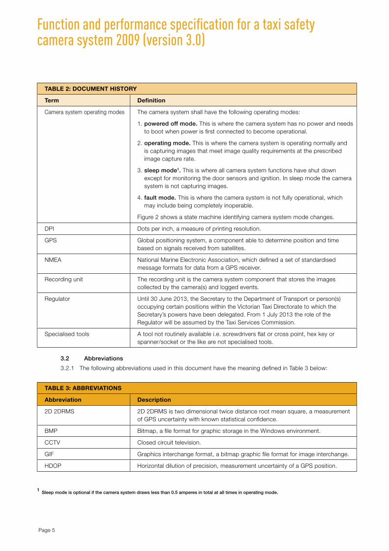
Camera system operating modes The camera system shall have the following operating modes:
1. powered off mode. This is where the camera system has no power and needs to boot when power is first connected to become operational.
2. operating mode. This is where the camera system is operating normally and is capturing images that meet image quality requirements at the prescribed image capture rate.
3. sleep mode1. This is where all camera system functions have shut down except for monitoring the door sensors and ignition. In sleep mode the camera system is not capturing images.
4. fault mode. This is where the camera system is not fully operational, which may include being completely inoperable.
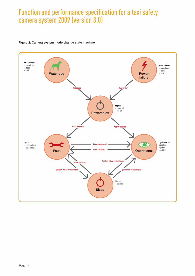
Figure 2 shows a state machine identifying camera system mode changes.
DPI Dots per inch, a measure of printing resolution.
GPS Global positioning system, a component able to determine position and time based on signals received from satellites.
NMEA National Marine Electronic Association, which defined a set of standardised message formats for data from a GPS receiver.
Recording unit The recording unit is the camera system component that stores the images collected by the camera(s) and logged events.
Regulator Until 30 June 2013, the Secretary to the Department of Transport or person(s) occupying certain positions within the Victorian Taxi Directorate to which the Secretary’s powers have been delegated. From 1 July 2013 the role of the Regulator will be assumed by the Taxi Services Commission.
Specialised tools A tool not routinely available i.e. screwdrivers flat or cross point, hex key or spanner/socket or the like are not specialised tools.
3.2 Abbreviations
3.2.1 The following abbreviations used in this document have the meaning defined in Table 3 below:
TablE 3: abbREVIaTIONS
abbreviation Description
2D 2DRMS 2D 2DRMS is two dimensional twice distance root mean square, a measurement of GPS uncertainty with known statistical confidence.
BMP Bitmap, a file format for graphic storage in the Windows environment.
CCTV Closed circuit television.
GIF Graphics interchange format, a bitmap graphic file format for image interchange.
HDOP Horizontal dilution of precision, measurement uncertainty of a GPS position.
1 Sleep mode is optional if the camera system draws less than 0.5 amperes in total at all times in operating mode.

Page 6
Function and performance specification for a taxi safety camera system 2009 (version 3.0)
TablE 3: abbREVIaTIONS
abbreviation Description
IP67 Ingress protection code 67, as specified by the United States National Electrical Manufacturers Association (NEMA)
JPEG Joint photographic expert group, file format for compression of images.
LED Light-emitting diode.
MTBF Mean time between failure.
RH Relative humidity.
TIFF Tagged image file format, file format used for graphic storage.
TVL Television lines, a tool for measuring image resolution.
USB Universal serial bus - a data and power connection between electronic devices.
UTC Coordinated universal time, time format resolved from a satellite transmission.
WAT Wheelchair accessible taxi.
4. REFERENCES
4.1 The following documents and/or standards defined in Table 4 are referenced in this specification and should be read in conjunction with this specification
TablE 4: REFERENCES
Reference number Document number Title
1 AS/NZS CISPR 22:2008 Radio disturbance characteristics for the protection of receivers used on board vehicles, boats, and on devices – limits and methods of measurement
2 ISO 10605:2001 Road vehicles – test methods for electrical disturbances from electrostatic discharge
3 ISO 7637-2:2004 Road vehicles – electrical disturbances from conduction and coupling – Part 2: electrical transient conduction along supply lines only
4 DOC/08/825527 National taxi security camera standards 2008 Version 4.5 Draft, March 2008
5 DOC-08-120250 Victorian taxi-cabs security camera specifications 2001 Taxi Services Commission Version 2.0 March 2002
6 AS 4806.2- 2006 Closed circuit television (CCTV) Part 2: application guidelines
7 IEC 60068-2 Basic environmental testing procedures – Part 2
8 IEC 60529 - 2004 Degrees of protection provided by enclosures (IP Code)
9 ASTM E119 Standard for fire resistance of equipment assembly
10 UL72 Standard for fire resistance of record protection equipment

Page 7
Function and performance specification for a taxi safety camera system 2009 (version 3.0)
5. SYSTEM CONSTRUCTION 5.1 The camera system shall be constructed such that the internal components including control unit
and camera housing does not have any sharp edges or protrusions that may cause injury to the taxi occupants or technician.
5.2 Any external camera fitted to the taxi shall be constructed such that the external camera housing does not have any sharp edges or protrusions that may cause injury to the general public or obstruct the field of view of the taxi driver. External cameras must be located within the outline of the vehicle.
5.3 The camera system shall be designed such that any adjustment in the alignment of the camera(s) requires the use of specialised tools.
5.4 All camera system components, including the camera housing and recording unit, shall be resistant to tampering, vandalism and/or degradation of the images by intentional or accidental damage. Refer to Annex A.
5.5 The recording unit shall be attached to the vehicle using tamperproof attachments, such that the recording unit cannot be removed from the attached position when applying 2000N tensile force. This is equivalent to a large person trying to remove the device using a one metre pinch bar as a lever.
5.6 All camera system components shall be easily interchangeable by authorised personnel in the event of failure or damage.
5.7 The camera system shall use non-volatile memory to store all captured images. The use of volatile memory is not permitted.
5.8 The camera system shall be designed and installed such that it may be easily tested by an approved agent or approved person to ensure that the system is functioning correctly and that images are being recorded as prescribed by these specifications. The testing of the camera alignment and image quality shall be through an easily accessible test point. This test point shall not allow an unauthorised person to obtain recorded material from the camera system.
5.9 The camera system with all components shall have a minimum mean time between failure (MBTF) of 50,000 hours (excluding careless or wilful damage).
5.10 The camera system shall be designed such that it is upgradeable to incorporate future enhancements. As far as is practicable such upgrades shall not require the replacement of system components.
5.11 The main housing of camera system shall be inscribed or imprinted with a unique serial number and the year of installation. This information is expected to be used by the regulator to retire old equipment.
6. SYSTEM ENVIRONMENTal REQUIREMENTS 6.1 The camera system shall be capable of functioning in the normal range of operating temperatures
found within the confines of a taxi:
1. minimum operating range: -5°C to +60°C; and
2. minimum non-operating range -10°C to +80°C.
The non-operating range specified is that where the camera system shall resume operation when the temperature returns to the prescribed operating range. Refer to Annex B.
6.2 The camera system and associated components shall be capable of functioning in the normal range of operating humidity which may be found in a vehicle operating in Victoria. As a minimum this range should be 0 to 85 per cent relative humidity, non-condensing. Refer to Annex B.
6.3 The camera system construction shall be such that the level of electromagnetic emissions does not interfere with other electronic systems on board the taxi. Conversely the camera system shall be protected from interference from sources of electromagnetic interference found in a taxi. Refer to Annex C.

Page 8
Function and performance specification for a taxi safety camera system 2009 (version 3.0)
6.4 Images from the camera system shall be capable of being recovered following submersion in fresh water or salt water to a depth of six metres for a minimum period of 72 hours. Refer to Annex D.
6.5 The camera system shall be constructed and installed in such a manner that following a vehicle fire, all images shall be readily recoverable. Refer to Annex E.
6.6 The camera system shall be impact and shock resistant, sufficient to withstand a typical car accident and withstand the regular vibration experienced by a taxi. Refer to Annex F.
6.7 Safety camera components mounted on the exterior of a taxi shall meet or exceed the IP67 rating.
7. SYSTEM POWER 7.1 The camera system shall be able to maintain operating mode, without interrupting continuous image
capture, with an input voltage range of at least 8 volts DC up to at least 18 volts DC, and shall be protected against reverse voltage, short circuits, and high voltage transients likely to be encountered in the vehicle’s electrical system (See Table 4 – References above.).
7.2 The camera system shall draw a maximum current of 2 amperes for each camera when taking images. The camera system shall draw no more than 0.5 amperes in total when in sleep mode.
7.3 A camera system in powered off mode shall boot and become operational within 30 seconds after stable operating power is supplied to the system.
7.4 Should the system voltage fall below the camera system’s minimum voltage limit then the system shall be permitted to enter powered off mode. The boot-up shall be logged. Refer to section 11.5.
7.5 The camera system, once in operating mode, shall remain operational for a minimum period of 30 minutes after the ignition is turned off whereupon it will go into sleep mode.
7.6 The camera system shall go into sleep mode if a door open event has not occurred for a period of six hours. This requirement is included to prevent images of a crime being overwritten in the event the vehicle is dumped with the ignition left on.
7.7 If the camera system is in sleep mode, the camera system shall wake and go into operating mode when either the vehicle ignition is turned on or when a door open event occurs – whichever occurs first.
7.8 When the camera system is powered on or the ignition is turned on the camera system shall perform a self test and if the self test fails go into failed mode.
7.9 The time for the camera system to attain operating mode from sleep mode shall be no more than three seconds.
7.10 With the exception of the powered off mode, all other camera system mode changes shall be logged. Refer to section 11.5.
7.11 The camera system shall not include a manual on/off switch that would allow the system to be turned off or in any way disabled during normal operation.
7.12 The connection to the vehicle power supply shall include:
1. fitting the power connection with non-removable fusing or protection; or
2. fitting the power connection with a sealed circuit breaker or similar.
7.13 In the event of a re-boot the camera system shall preserve all images captured up to the point at which the re-boot event occurred.

Page 9
Function and performance specification for a taxi safety camera system 2009 (version 3.0)
8. INTERFaCE REQUIREMENTS 8.1 Figure 1 depicts the identified interfaces to the camera system ‘control unit’.
8.2 Camera systems will be required to be fitted to a number of different vehicle types with many differing connection points and associated signal levels. As such the supplied system shall be capable of being programmed for these differing signals and have simple interface cabling.
8.3 The camera system shall be connected to the vehicle power system and shall be able to detect the voltage levels provided.
8.4 If a duress alarm is fitted to the vehicle, the camera system shall be provided with a physical interface to the duress alarm which shall notify the camera system of the activation of a duress event.
8.5 If a duress alarm is not fitted to the vehicle, a switch shall be fitted as prescribed by the Regulator and activation of the switch shall signal to the camera system that a duress event is occurring.
8.6 The camera system shall be able to detect an ‘ignition on’ and ‘ignition off’ event.
8.7 The camera system shall be able to detect a door event, by detection of any ‘door open’ or ‘door close’ (refer to section 12.2.1). The door status monitor shall not be dependent on unreliable vehicle components, such as interior roof lights, which may be inoperative or defective.
8.8 For a wheelchair accessible taxi the status of the rear door(s)/tailgate shall be included in the door event detection.
8.9 The camera system shall be able to detect the taximeter ‘hired’ status.
8.10 The camera system shall have an inbuilt GPS receiver.
8.11 Optionally, the camera system shall be able to detect the vehicle speed.
8.12 The camera system shall provide one or more external interface(s) for the connection of a laptop (or similar) to allow authorised personnel to download images, configure the camera system and to align the Cameras.
8.13 An optically isolated NPN open collector (NPN transistor or equivalent) output, capable of sinking a minimum of 100 mA, shall toggle at a half second rate whilst the camera system is in operational mode. In fault mode the output shall remain on, in power off and sleep modes the output shall remain off. The purpose is to provide a ‘health’ heartbeat to other (future) taxi technology.

Page 10
Function and performance specification for a taxi safety camera system 2009 (version 3.0)
Figure 1: Camera system control unit interfaces

Page 11
Function and performance specification for a taxi safety camera system 2009 (version 3.0)
9. FITTING aND INSTallaTION 9.1 Fitting and installation shall include programming of the camera system to:
1. correctly store the identification (registration number) of the taxi that the system is being fitted to; and
2. correctly initialise the UTC date and time that will be used to time stamp the images that are captured.
9.2 The camera(s) shall at all times provide a clear view of the taxi driver and all forward facing passengers when seated inside the vehicle. In addition the camera(s) shall provide a view of any person approaching (from up to three metres and a minimum field of view of 70 degrees relative to the driver’s window) or standing at the driver’s window. To meet this requirement it may be necessary to install one or more internal cameras and one or more external cameras2.
9.3 The field of view of the camera(s) shall not be obscured, or be capable of being obscured either permanently or temporarily, by any sun visor or other fitting or equipment installed inside or outside the vehicle.
9.4 The internal camera(s) shall be readily visible to passengers in the vehicle.
9.5 All camera(s) shall be mounted in such a manner so as to prevent intentional or unintentional misalignment of the field of view, except in the case of a vehicle accident or other severe impact.
9.6 Optional additional internal cameras can be fitted but shall comply with image quality requirements specified for the system and shall be fitted in an approved manner and location and shall not reduce the amount of memory for images otherwise available to the camera(s) required to satisfy sections 9.2 and 12.1.3.
9.7 The installation of the camera system (and any additional optional cameras and accessories, e.g. supplemental lighting on B-pillars) shall not affect the continued compliance of the taxi with all other relevant legislative requirements, including the Transport (Compliance and Miscellaneous) Act 1983, Road Safety Act 1986 and the Australian Design Rules.
9.8 The camera system shall be capable of being installed in a variety of vehicles including but not limited to sedans, station wagons, high occupancy and wheelchair accessible vehicles that are approved for use as taxis within the operating jurisdiction.
9.9 The internal camera housing(s) shall be positioned such that passengers or drivers do not come into contact with the housing during normal operation.
9.10 The cameras and all system components shall be installed in a manner that does not interfere with the driver’s vision or view of mirrors or otherwise normal operation of the vehicle.
9.11 Apart from the camera unit, internal supplemental lighting (if required) and GPS receiver/antenna, all other components of the camera system shall be concealed.
9.12 All cabling associated with the camera system shall be concealed and be, as far as practicable, tamper-proof and vandal resistant.
9.13 Signal cabling shall have appropriate characteristic impedance, attenuation and shielding necessary to meet all performance requirements.
9.14 All components of the camera system shall require specialised tools for removal.
9.15 Installation of the recording unit shall include easy access to the connection point to obtain recorded material and access to the connection point shall not require any dismantling of vehicle fittings or the recorder unit. Any connection point (e.g. USB port for download) shall be protected from contamination (e.g. dirt and moisture) which would prevent easy connection and reliable operation by authorised personnel.
2 Reference to an internal camera shall apply to all internal cameras and a reference to external cameras shall apply to all external cameras.

Page 12
Function and performance specification for a taxi safety camera system 2009 (version 3.0)
9.16 The camera system shall be provided with comprehensive installation and set up instructions in printed or electronic format including, but not limited to, the necessary information to enable the installation, commissioning and maintenance of the system. This information shall only be made available to persons approved by the Regulator.
9.17 The camera system shall be provided with clear and concise operating instructions, which shall take account of the needs of operators and drivers for whom English is not the first language. These instructions shall comprise printed materials, a copy of which shall be supplied with each camera system installed.
9.18 The camera system shall be provided with pre-set configuration parameters. Refer to Annex G.
9.19 If the camera system has removable memory then it shall only be able to be removed by persons authorised to do so.
10. CaMERa SYSTEM OPERaTION
10.1 Normal operation
10.1.1 The system shall provide full and reliable functionality in all operational and environmental conditions encountered in the normal operation of taxis.
10.1.2 Once in operating mode the camera system shall continuously record images as specified in sections 12 and 13.
10.1.3 If it is necessary to suspend the camera system image recording during connection to a laptop (or similar) for the purposes of image download and/or technician access, then:
1. image capture shall only be suspended after verifying that such access is authorised (e.g. via compliant application software and user authentication);
2. the camera system shall resume normal recording within 10 seconds of the download session or technician access terminating; and
3. the camera system shall terminate an authorised access session after 10 minutes of inactivity (i.e. if the laptop is left unattended).
10.2 Operational failure
10.2.1 In the event that the camera system cannot accurately and reliably capture images as defined in sections 12 and 13, the camera system shall be deemed to have a system fault and be placed into fault mode. Reasons that the camera system shall be placed into fault mode shall include, but not be limited to, the following:
1. images are not being recorded from any camera that is supposed to be capturing images;
2. failure to record images as described in section 12;
3. failure of GPS receiver;
4. failure of the door interface, e.g. cannot determine ‘door open’; and
5. self test failure.
10.2.2 For the purposes of section 10.2.1, failures which place the camera system continuously into fault mode are expected to require intervention from a camera technician to resolve.
10.2.3 The camera system, with the exception specified in section 10.2.4, shall remain in fault mode until all system faults are cleared and the camera system is continuously recording images as per section 10.1.2, whereupon the camera system shall be placed in operating mode.

Page 13
Function and performance specification for a taxi safety camera system 2009 (version 3.0)
10.2.4 The camera system in fault mode shall be placed in sleep mode if no activity has occurred as specified in sections 7.5 and 7.6.
10.2.5 In fault mode the camera system shall capture images if it is able to do so. For example, failure of a single camera should not stop the recording of images from other cameras or failure of supplemental lighting shall not stop the recording of images albeit with poor contrast.
10.2.6 The camera system shall include a ‘hardware watchdog’ or similar mechanism. The watchdog shall monitor the camera system image collection and recording. In the event that the watchdog determines the camera system is not recording images in the prescribed manner, the watchdog shall place the camera system into powered off mode whereupon it can ‘re-boot’ in an attempt to clear the error.
10.3 Operational indicators
10.3.1 The driver and passenger(s) shall have a visual indicator showing when the system is operational and when there is a malfunction. This indicator shall be in a form approved by the Regulator. The camera system shall incorporate the following minimum features:
1. in operating mode shall display a green LED;
2. upon entering operating mode the red LED shall flash twice;
3. in fault mode shall display a red LED, oscillating flash;
4. an oscillating flash shall be of not less than 250 ms and not greater than 500 ms; and
5. in powered off mode shall have no LED display.
10.3.2 Figure 2 shows a state machine identifying camera system mode changes and associated indicator light status.
10.3.3 Where the camera system is fitted with an indicator to show that it is powered on, this indicator shall be separate to those described in section 10.3.1, and/or of a different colour to avoid any possible confusion on the part of drivers using the system.
10.3.4 Optionally, additional indicators may be provided but these should be designed so as to avoid confusion with the two mandatory indicators nominated in this requirement. Where optional indicators are proposed, the colour, purpose and location of each indicator shall be identified in the operating instructions.
Page 14
Function and performance specification for a taxi safety camera system 2009 (version 3.0)
Figure 2: Camera system mode change state machine
Watchdog Powerfailure
Fault Operational
Sleep
Powered off
Lights:– green optional– red flashing
Lights:– optional
Lights:– green off– red off
Lights normaloperation:– green– red Off
From Modes:– operational– sleep– fault
From Modes:– operational– sleep– fault
Watchdog
Fault detected
Ignition off or no door open
Ignition off or no door open
Ignition on or door open
Fault detected
Fault detected
All faults cleared
Power applied
Power fail

Page 15
Function and performance specification for a taxi safety camera system 2009 (version 3.0)
11. SYSTEM lOGGING REQUIREMENTS 11.1 The camera system shall retain three logs of events which influence the camera operation and access
made by an external computer or similar. These logs shall be called the ‘access log’, the ‘technician log’ and the ‘diagnostic log’.
11.2 The access log shall record the following events:
1. downloading of images stored in the recording unit to an external computer.
11.3 The technician log shall record the following events:
1. setting or changing of system parameters, including the old and new values of the changed parameters; and
2. viewing test images for installation and alignment purposes.
11.4 The access log and the technician log shall be able to record a minimum of 100 accesses to the camera system. If more events need to be recorded than space permits in the log, the oldest events shall be overwritten by new events.
11.5 The diagnostic log shall record, as a minimum, the following events:
1. all events logged in the access log and technician log;
2. system mode changes and reason; and
3. any failure or event that prevents images from being recorded as described in sections 12 and 13.
11.6 For each event in sections 11.2, 11.3 and 11.5 the log file shall include, but not be limited to:
1. for camera system access events, identification of person(s) and external computer accessing the camera system the time and date that the access occurred and the action(s) undertaken during the entire period of the access; and
2. identification of event start date and time and if appropriate the duration or end date and time of the event.
11.7 The size of the diagnostic log file (one or more files) referred to in section 11.5 shall be such that any logged event shall be retained for a minimum period of 90 days.
11.8 The log files shall only be able to be modified by the camera system.
11.9 Suitable security measures shall be implemented to restrict viewing of the log files to only those persons authorised to view them. The log files may only be viewed by a person authorised to perform downloads or an authorised safety camera technician. Only these users shall only be able to read or extract the log files.

Page 16
Function and performance specification for a taxi safety camera system 2009 (version 3.0)
12. IMaGE RECORDING
12.1 Image recording system
12.1.1 The camera system shall capture and store images that meet the image appearance requirements detailed in section 13.
12.1.2 The camera system must operate in a continuous recording mode. A continuous recording camera system is one that records images on a fixed periodic basis independently of any external trigger. However, the camera system is required to monitor specific tag events by means of connections to appropriate status points in the vehicle electrical system.
12.1.3 The system shall be capable of continuously recording images for a minimum of 72 hours3.
12.1.4 The minimum recording capacity includes all times that the camera is in operating mode.
12.1.5 The maximum time interval between recording any two images per camera is one second. There is no specified minimum time interval between recording any two images. Optionally, any Camera used to provide a view of the driver’s exterior door area only needs to capture images while the vehicle is stationary or near stationary.
12.1.6 For the avoidance of doubt any reference to image tagging shall be interpreted as recording information concerning the status of the tag at the time the image is captured. When downloading or viewing any image it shall be possible to also see the associated tag event information.
12.1.7 The cameras shall have a maximum (time duration) effective shutter speed of 1/25 second.
12.1.8 In accordance with Australian Standard AS4806.2 (Reference 6) for face identification, the stored image shall record a minimum of 360 pixels per metre both horizontally and vertically at the target. Where the target is a normally seated passenger, a normally seated driver, or a person outside the taxi standing up to one metre away from the driver’s window.
12.1.9 The camera system shall store images with a minimum of 256 greyscale levels.
12.1.10 The camera shall capture monochrome images. The use of colour images is permitted, subject to the camera providing an equivalent image resolution and quality to that of a monochrome camera in normal lighting conditions and the camera reverting to monochrome operation in low light conditions.
12.1.11 The recording system shall be configured such that the recording medium shall automatically commence re-recording once the medium has reached its recording capacity. The oldest image(s) shall be overwritten first.
12.1.12 The captured images and any associated metadata shall be authenticated using an authentication coding scheme suitable for evidentiary substantiation. An internationally recognised authentication scheme is preferred.
12.1.13 The images, including the authentication coding created in section 12.1.12, shall be stored as encrypted data which is not readily decrypted into a clear image without using the Download Program. Images shall not be stored in non-volatile memory without being encrypted. An internationally recognised encryption algorithm is preferred.
12.1.14 The supplier shall take reasonable steps to ensure that any encryption keys or proprietary algorithms, used to satisfy clause 12.1.13, are protected from unauthorised use. The supplier shall use recognised industry standard key management practices to prevent unauthorised persons obtaining the keys or algorithms for the purpose of viewing images.
3 72 hours is three days continuous recording.

Page 17
Function and performance specification for a taxi safety camera system 2009 (version 3.0)
12.2 Tag event recording
12.2.1 The system shall be capable of monitoring the status of any door in the taxi. When the first of any door, including the driver’s door, is opened, the system shall tag all images immediately following the door opening with a suitable status message such as ‘door open’. Tagging shall continue until such time as the last door is closed.
12.2.2 The system shall be capable of monitoring the taxi duress alarm. Activation of the taxi duress alarm shall tag all images immediately following the activation of the duress alarm for the next five minutes with a suitable status message such as ‘duress’.
12.2.3 The system shall be capable of monitoring the taximeter. The camera system shall tag all images from flagfall to meter cleared with a suitable status message such as ‘meter on’ and all images from meter cleared to flagfall with a suitable message such as ‘meter off’.
12.3 Time and location recording
12.3.1 Each image shall be tagged with the location (latitude and longitude) and time that the image was captured.
12.3.2 The location tag of latitude and longitude referred to in section 12.3.1 shall be provided by the inbuilt GPS receiver in the camera system.
12.3.3 If a valid location tag of latitude and longitude referred to in section 13.7 cannot be temporarily ascertained (e.g. in an underground car park or tunnel), the location tag shall be deemed to be uncertain.
12.3.4 For the purpose of section 12.3.3, valid shall mean when the 2D 2DRMS of the position message is less than 25 (an HDOP of approximately 12 metres). This means a 95 per cent confidence that the actual location will be within a circle of 25 metre radius from the reported position.
12.3.5 The time tag referred to in section 12.3.1 shall be provided by the camera system’s internal time reference and shall indicate whether the time is valid.
12.3.6 The camera system’s internal time reference which is used to time stamp images shall be corrected for local drift by regular synchronisation to the UTC time stamp of the GPS source. If the internal time reference has not been corrected within the last 24 hours it is deemed to be uncertain.
12.3.7 The time reference shall not exhibit local drift of more than 10 seconds in a 24 hour period.
12.4 Audio recording system4
12.4.1 The camera system shall have the capability to record audio within the interior of the taxi. camera systems supplied to the Victorian taxi market shall have the audio recording system disabled5.
13. IMaGE aPPEaRaNCE 13.1 The resolution and clarity of the recorded image from the camera(s) shall be maintained under all
lighting conditions from darkness (no light in the visible spectrum) through to bright sunlight.
13.2 All forward facing occupants of the vehicle are to be clearly visible in the captured images taken from the internal camera(s). For the purposes of clarification, clearly visible means that any normally seated forward facing person occupying any seat in the taxi must be clearly identifiable, in the captured image. For each occupant the captured image shall include their entire upper body from the waist to the head.
4 The recording of audio is not currently permitted in taxis by law in the state of Victoria.
5 An audio recording device has been included for compatibility with other Australian jurisdictions that mandate or permit audio recording.

Page 18
Function and performance specification for a taxi safety camera system 2009 (version 3.0)
13.3 The stored image, (after accounting for lens optical degradation, filtering, compression and quantisation effects) shall provide high quality images when printed on a laser printer. These images shall allow the identification of people in the taxi or approaching the driver’s window, in ambient lighting ranging from darkness (0 lux – expected to require supplemental lighting) through to bright sun-light (100,000 lux). Refer to Annex H.
13.4 The camera lenses shall have an auto iris or electronic auto-exposure adjustment facility such that image clarity is not adversely affected by light fluctuations.
13.5 Supplementary lighting, if fitted, may be used to enhance the resolution of persons which are being silhouetted by an external light source being directed into the camera lens.
13.6 The lenses fitted to both internal and external cameras shall be capable of maintaining images in focus at any distance between 300 mm and three metres from the lens.
13.7 All downloaded images (either displayed on a computer terminal or printed) shall include in their rendering the following information:
1. location, both the latitude and longitude to a precision of better than five metres determined from the GPS tag, or ‘no fix’ if the GPS location is uncertain;
2. timestamp, the date and time determined from the timestamp tag, to a precision of 1/100 second, appended with an ‘*’ (asterisk) or similar symbol if the camera system is uncertain;
3. duress tag value;
4. meter tag value;
5. door open tag value; and
6. taxi identification (registration number).
13.8 For the purposes of clarification the information referred to in this section should be positioned within the image such that it does not obstruct the view of any occupant in a seated position within the vehicle or a person standing outside the driver’s window.
13.9 For the avoidance of doubt, the information specified in section 13.7 shall be clearly visible when viewing the image in its electronic format using the download software. In addition the information shall be clearly visible on any images that are printed or exported to external media. In the case of external media it shall be possible to view the image plus related information concerning the taxi, date time and location using industry standard image viewing software. Refer to section 14.4 for details of the types of file format to be supported.
14. IMaGE DOWNlOaD 14.1 The supplier of the camera system shall provide download software, to the Regulator, for the secure
download and viewing of images from the camera system. Use of this software shall be the only method of downloading images from the camera system. Download software shall not be provided to any unauthorised persons.
14.2 The time taken for the download of images stored in the recording unit shall not exceed 15 minutes per camera for 24 hours of images. For the purposes of clarification the 15 minutes includes the time required to download the encrypted image files for a specific camera system to the download (laptop) computer and the time taken to decrypt them into a clear format for image viewing purposes.
14.3 The download software shall download encrypted images from the camera system to the download computer. Any downloaded images required for evidentiary purposes need to be saved to external disk media in both encrypted and unencrypted form.

Page 19
Function and performance specification for a taxi safety camera system 2009 (version 3.0)
14.4 It shall be possible to export images recovered from the camera system to an external media in both encrypted and unencrypted format. The unencrypted images shall be formatted using formats including, but not limited to, industry standards JPEG and BMP.
14.5 Download of images shall be able to be specified with a starting time granularity in one hour increments and a download time period in one hour increments. For example, by specifying ‘2008-06-01, 4am, four hours’; all images acquired during the period 2008-06-01 from 4am-8am will be downloaded.
14.6 The software referred to in section 14.1 shall be able to operate on a commercial off the shelf (COTS) laptop computer.
14.7 The image downloading software shall provide a log of all access to the software by users. Events to be logged, with a date and timestamp to a precision of one second, shall include:
1. logon of each user;
2. connecting to a camera system;
3. downloading images stored in the recording unit;
4. attempted modification or manipulation of image files stored on the downloading computer;
5. printing images stored on the downloading computer; and
6. exporting images stored on the downloading computer to an external media file.
14.8 For each event in requirement 14.7 the image software download log file(s) shall include, but not be limited to, identification of persons accessing the downloading software, the time and date that the access occurred and the action(s) undertaken during the entire period of the access. The size of the software download log file shall be such that the any logged event shall be retained for a minimum period of 12 months.
14.9 The log file referred to in section 14.7 and 14.8 shall be stored in non-volatile memory on the downloading computer and shall be protected against unauthorised access. The supplier shall take reasonable steps to prevent deletion of the log file(s) or any individual entry in the log using the downloading software or any other software provided by the manufacturer to authorised persons.
14.10 It shall not be possible to download images using download software from a camera system in another jurisdiction (for example: a Victorian authorised download officer shall not be able to download images from a NSW taxi camera. This requirement extends to prevent downloading images taken by a camera system installed in a Victorian taxi on supplier’s downloading software in another state or territory).
14.11 The supplier’s download software shall be password protected to prevent the unauthorised viewing, recovery or reproduction of images. Where an image is stored on the hard drive of a computer, access to the image shall be protected by password so that it cannot be viewed, copied, printed or otherwise reproduced by an unauthorised person.
14.12 The download software shall be able to determine if an image has been manipulated in any way whilst held on the camera system or on another external storage medium by reference to the authentication coding held with the image.
14.13 It shall be possible to print images recovered from the camera system on a standard laser printer using the download software.
14.14 The use of image compression techniques is permitted subject to the image resulting from the application of image compression meeting the relevant evidentiary requirements for legal action.

Page 20
Function and performance specification for a taxi safety camera system 2009 (version 3.0)
14.15 The download software shall provide the authorised download officer with the ability to easily locate the images required. A sample list of facilities expected to be available are:
1. display images from a camera in time order;
2. single image step forwards or backwards);
3. fast play forwards (multiple images per second);
4. display of filtered tagged event data by time and date;
5. jump to start, end, time of day or specific tagged images;
6. jump by preset increments (typically one minute and 10 minutes);
7. pause;
8. synchronous display of images of all cameras on a split screen;
9. image zoom;
10. selection of appropriate images for exporting and printing; and
11. display timestamps in Australian Eastern Standard Time or Australian Eastern Daylight Savings Time (as applicable at the time).
aNNEX a – RESISTaNCE TO VaNDalISMThe purpose of section 5.4 is to ensure that the construction of the camera system is such that it will provide reasonable protection to the images that are stored in the memory. The Regulator does not specify particular tests that need to be successfully undertaken in order to meet section 5.4.
The supplier may optionally provide details of any testing that has been undertaken to provide resistance to vandalism.
aNNEX b – RaNGE OF OPERaTING TEMPERaTURESThe purpose of sections 6.1 and 6.2 is to ensure that the complete camera system has been tested to ensure that it will operate reliably in a range of temperatures and humidity that will be experienced in a taxi. It is expected that camera systems that are being nominated for approval in Victoria will have been tested to ensure that they will be meet this requirement.
The supplier is to provide details of the testing that has been undertaken to meet sections 6.1 and 6.2, together with test results.
aNNEX C – ElECTROMaGNETIC COMPaTIbIlITYThe purpose of section 6.3 is to ensure that the complete camera system has been tested to ensure that it will not interfere with other electronic systems found in a taxi or that other electronic systems will not cause the system to operate unreliably. It is required that the supplied equipment conform to applicable Australian electromagnetic compatibility standards current at the time of supply of the camera system.
The current applicable standards are AS/NZS CISPR 22:2008, ISO 10605:2001 and ISO 7637-2:2004 (References 1–3).
The camera system shall meet the following acceptance levels:
1. Reference 1, AS/NZS CISPR 22:2008: Level 3, ISO Class A; and

Page 21
Function and performance specification for a taxi safety camera system 2009 (version 3.0)
2. Reference 2, ISO 10605:2001;
Camera system Discharge Network level
Unpowered Contact 150pF/2kΩ ±8kV
Air 330pF/2kΩ ±15kV
Powered Contact 150pF/2kΩ ±8kV
Air 330pF/2kΩ ±25kV
Recording unit, ISO Class B;
Camera, ISO Class C; and
Supplementary lighting (if fitted), ISO Class C; and
3. Reference 3, ISO 7637-2:2004: Level IV, ISO Class A.
The ISO failure mode severity classifications are:
(A) All functions of the device or system perform as specified during and after exposure to interference.
(B) All functions of the device or system continue to functionally perform during exposure; however some functions may go beyond specified tolerance. All functions return automatically to within specification after exposure is removed. Memory function shall remain Class A.
(C) Device or system may not perform correctly during exposure but will return automatically to within specification after exposure is removed.
The supplier is to provide details of the testing that has been undertaken to meet section 6.3, together with test results.
aNNEX D – SUbMERSION PROTECTIONThe purpose of section 6.4 is to ensure that the recording unit can withstand immersion in saline or fresh water for a minimum period of three days. This simulates the potential effect of a taxi being accidentally or deliberately submersed in water.
A specific test methodology to prove compliance is not prescribed but the following is provided for guidance:
1. a test duration of 72 hours should be seen as a minimum requirement, longer test periods are encouraged;
2. a five per cent saline solution should be used for the test; and
3. the test may be executed by completely immersing the recording unit in a six metre column of saline water; or
4. the test may be executed by completely immersing the recording unit in a small volume of water and using an external pressure source to raise the water pressure to the required level (approximately 59 kPa).
The testing should ensure that images stored in the recording unit prior to immersion are successfully recovered at the end of the test period.
It is preferred that the test should be made on the image store in-situ within the recording unit rather than stand-alone.
The supplier is to provide details of the testing that has been undertaken to meet section 6.4 together with test results.
aNNEX E – RESISTaNCE TO a VEHIClE FIREThe following minimal standards/tests are defined in the interests of setting an objective specification for the recording unit to be deemed as being able to provide ‘resistance to vehicle fire’. This specification is based on the lowest temperature tests defined in ASTM E119 and UL 72.
Page 22
Function and performance specification for a taxi safety camera system 2009 (version 3.0)
The recording unit with all wiring leading externally from the recording unit in place, (optionally including the camera system) may be certified as fire resistant to 538°C (1000°F) as per ASTM E119 methodology or equivalent certification6.
Alternatively the camera system can be tested using the basic fire test as described below7.
The basic fire test comprises the following steps:
1. a furnace is to be heated to 538°C (1000°F);
2. the recording unit (either by itself or housed in the camera system) including pre-recorded information and images, is to be placed in the furnace;
3. after five minutes at 538°C (1000°F) the furnace is switched off; and
4. the equipment is immediately removed from the furnace.
Once the recording unit is removed from the furnace (and allowed to cool to room temperature) the information that was contained on the recording unit prior to it being placed in the furnace must be recovered.
The supplier is to provide details of the testing that has been undertaken to meet section 6.5, together with test results.
aNNEX F – IMPaCT aND SHOCK RESISTaNCEThe purpose of section 6.6 is to ensure that the camera system can withstand the vibration that will be experienced during the normal operation of a taxi. In addition the recording unit of the camera system is expected to survive the shock waves that are experienced during a vehicle impact event, such as a moving traffic accident.
The current applicable standards are IEC 68-2-6 method 514.5 and IEC 68-2-27 method 516.5 (Reference 7).
The supplier is to provide details of the testing that has been undertaken to meet section 6.6, together with test results.
aNNEX G – SYSTEM PaRaMETER SETTINGThe purpose of this requirement is to ensure that camera systems are not installed incorrectly.
The camera system should be supplied so that minimal configuration by the installation technician is required. The installation technician should only be required to physically install the camera system, connect to the appropriate tag points, initialise the vehicle number, install the GPS antenna, connect to the battery, confirm that the cameras are aligned and verify the camera system is operating correctly.
The supplier is to provide details of the installation procedures to the Regulator.
aNNEX H – IMaGE VERIFICaTIONThe purpose of this test is to provide a minimum test for the quality of images produced by the camera system. The image quality test has two parts: a set of tests under static conditions with objective measurement criteria, and dynamic tests under mobile conditions with subjective assessment of the results.
Static test
The static tests need to be conducted with test cards provided by the TSC8.
The static tests shall be conducted in a controlled environment (a laboratory) by following the steps detailed below:
1. set the laboratory temperature in the range of 25°C to 30°C;
2. set up a camera system with its supplemental lighting in the laboratory – but do not turn it on;
6 For example: UL 72 Class 125 5 Minute Ratings at 538ºC (1000ºF) has not been explicitly stated because it applies to storage of materials in safes.
7 The basic fire test is less stringent than the fire resistant certification proposed above but allows suppliers using storage components certified to ASTM E119 (or similar) to claim compliance with this requirement.
8 TSC will provide two test charts in PDF format which can be printed and used to determine whether an image is deemed to meet the person identification and dynamic range requirements.

Page 23
Function and performance specification for a taxi safety camera system 2009 (version 3.0)
3. the camera shall be set for the standard fixed focal length and field of view to be used in an actual vehicle installation;
4. locate the test chart(s) on a stand perpendicular to the camera field of view centre line at the prescribed distance;
5. set the laboratory room to the prescribed lighting level;
6. turn the camera system on; and
7. once the camera system has reached a stable state, record some images.
The test should be performed for the combination of each lighting level and each distance specified below.
The static test shall use the following lighting levels (to be verified by measurement with a calibrated lux meter at the target test card):
1. near total darkness < 0.2 lux;
2. suburban side street lighting 0.5 -1.5 lux;
3. office lighting – 500 - 1,500 lux;
4. bright daylight on a clear day –50,000 - 100,000 lux.
The static test shall use the following distances:
1. for the internal camera with a front and back seat view of a sedan type vehicle – 1,500 mm; and
2. for the external camera – 1000 mm.
The captured images shall be recovered using the image download software and printed to a laser printer at least 600 dpi resolution.
Each of the images captured during the tests shall:
1. Provide an image resolution of at least 360 pixels per metre vertically and horizontally;
2. Using the TSC supplied test card clearly identify the four distinct lines at the 400 TVL mark both vertically and horizontally; and
3. Using the TSC supplied test card, clearly identify the 10 large shaded patches.
Dynamic (mobile) test
The dynamic tests shall be conducted on a system installed in a standard sedan of a type commonly used as a taxi9 in Victoria to closely reflect real life day and night conditions and allow a mobile test.
With the system installed in a vehicle, three test drives shall be undertaken in a suburban area:
1. once in the middle of the day;
2. once at evening twilight; and
3. once at night.
Each test drive shall include:
1. an approach to the driver window by at least two people abreast;
2. passengers entering and leaving the vehicle; and
3. 10 minutes of driving whilst passengers move around and look at each other and out various windows in a random manner whilst the vehicle is driven at 50 km/h or as driving conditions allow.
9 The camera system is not to be installed in a taxi for these test purposes.

Page 24
Function and performance specification for a taxi safety camera system 2009 (version 3.0)
The drive route shall comprise a circuit to ensure all sun or lighting angles are captured. At the start of the circuit the lighting levels should be measured with the lux meter.
The captured images shall be recovered using the image download software and a selection of images printed to a laser printer of at least 600 dpi resolution.
The images captured during each test shall:
1. show that all persons remain in focus during the trip. There should be no significant degradation caused by the movement of the vehicle and the changing lighting conditions;
2. show that the images of the faces shall not be significantly degraded or rendered unidentifiable by flaring, image darkening or wash out caused by changing lighting conditions.
The supplier is to provide details of the testing that has been undertaken to meet the requirements outlined above, together with test results.
aNNEX I – RESOlUTION CalCUlaTIONThe purpose of this Annex is to show the calculation used to define the image resolution.
Assumptions:
The determination is based on AS4806.2 (Reference 6).
AS4608.2 specifies that a person can be identified if their body occupies a full image of 720x576 pixels. Further it assumes that the head height is 15 per cent of the body, which equates to the image of the head requiring 86 pixels vertically for the person to be identified.
Assuming the following:
1. vertical and horizontal pixel equivalence; and
2. passengers are 160 cm tall (average Australian adult female height is 161 cm).
This equates to a head height of 24 cm. Which in turn equates to 360 pixels per metre [head pixels x heads per metre = 86 x (1/0.24 m)].
Two examples of image resolution that meet this criterion are shown below, assuming:
1. the horizontal pixels required to be collected and saved in the image are (2*PI*R)*(field view arc/360)*(pixels per metre).
2. the passenger is 160 cm from the camera.
Example 1: Camera lens angle 60 degrees horizontally
Horizontal pixels =
2 x PI x (160/100) x (60/360) x 360 = 603 pixels
Example 2: Camera lens angle 120 degrees horizontally
Horizontal pixels =
2 x PI x (160/100) x (120/360) x 360 = 1206 pixels
Page 25
Function and performance specification for a taxi safety camera system 2009 (version 3.0)
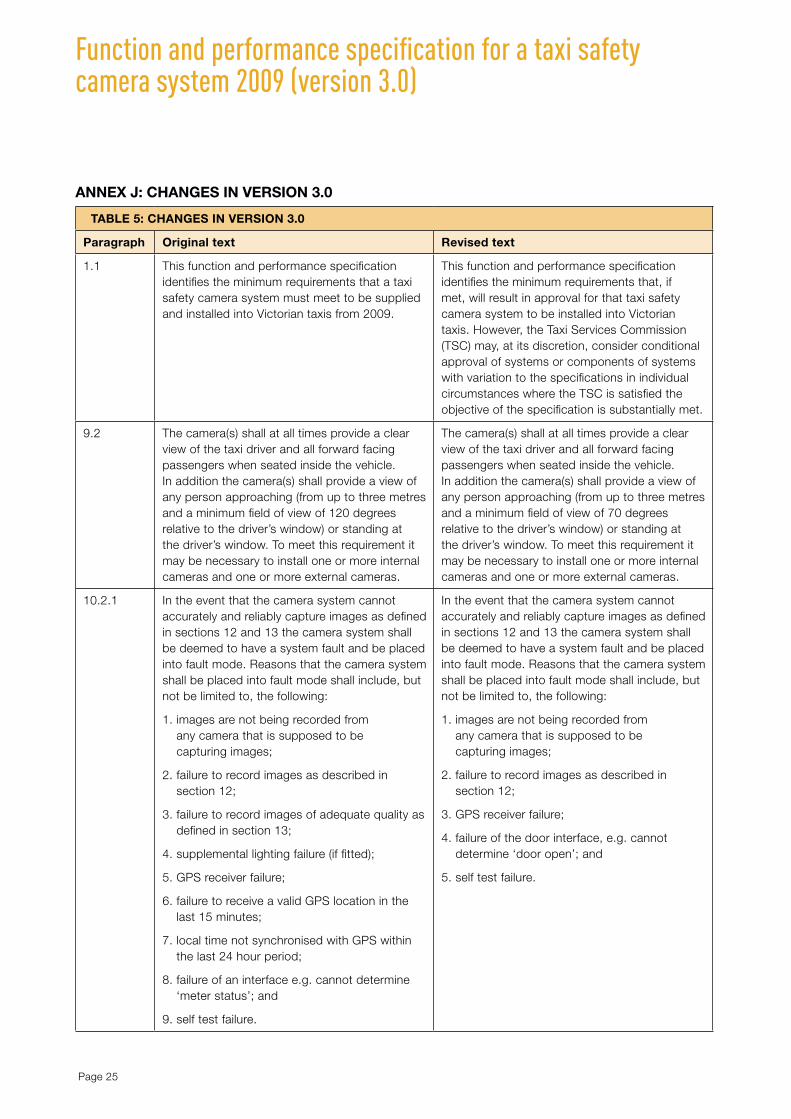
aNNEX J: CHaNGES IN VERSION 3.0
TablE 5: CHaNGES IN VERSION 3.0
Paragraph Original text Revised text
1.1 This function and performance specification identifies the minimum requirements that a taxi safety camera system must meet to be supplied and installed into Victorian taxis from 2009.
This function and performance specification identifies the minimum requirements that, if met, will result in approval for that taxi safety camera system to be installed into Victorian taxis. However, the Taxi Services Commission (TSC) may, at its discretion, consider conditional approval of systems or components of systems with variation to the specifications in individual circumstances where the TSC is satisfied the objective of the specification is substantially met.
9.2 The camera(s) shall at all times provide a clear view of the taxi driver and all forward facing passengers when seated inside the vehicle. In addition the camera(s) shall provide a view of any person approaching (from up to three metres and a minimum field of view of 120 degrees relative to the driver’s window) or standing at the driver’s window. To meet this requirement it may be necessary to install one or more internal cameras and one or more external cameras.
The camera(s) shall at all times provide a clear view of the taxi driver and all forward facing passengers when seated inside the vehicle. In addition the camera(s) shall provide a view of any person approaching (from up to three metres and a minimum field of view of 70 degrees relative to the driver’s window) or standing at the driver’s window. To meet this requirement it may be necessary to install one or more internal cameras and one or more external cameras.
10.2.1 In the event that the camera system cannot accurately and reliably capture images as defined in sections 12 and 13 the camera system shall be deemed to have a system fault and be placed into fault mode. Reasons that the camera system shall be placed into fault mode shall include, but not be limited to, the following:
1. images are not being recorded from any camera that is supposed to be capturing images;
2. failure to record images as described in section 12;
3. failure to record images of adequate quality as defined in section 13;
4. supplemental lighting failure (if fitted);
5. GPS receiver failure;
6. failure to receive a valid GPS location in the last 15 minutes;
7. local time not synchronised with GPS within the last 24 hour period;
8. failure of an interface e.g. cannot determine ‘meter status’; and
9. self test failure.
In the event that the camera system cannot accurately and reliably capture images as defined in sections 12 and 13 the camera system shall be deemed to have a system fault and be placed into fault mode. Reasons that the camera system shall be placed into fault mode shall include, but not be limited to, the following:
1. images are not being recorded from any camera that is supposed to be capturing images;
2. failure to record images as described in section 12;
3. GPS receiver failure;
4. failure of the door interface, e.g. cannot determine ‘door open’; and
5. self test failure.

Page 26
Function and performance specification for a taxi safety camera system 2009 (version 3.0)
TablE 5: CHaNGES IN VERSION 3.0
Paragraph Original Text Revised Text
10.3.1 The driver and passenger(s) shall have a visual indicator showing when the system is operational and when there is a malfunction. This indicator shall be in a form approved by the Regulator. The camera system shall incorporate the following minimum features:
1. in sleep mode shall have no LED display;
2. in operating mode shall display a green LED, static display. In addition, when in operating mode the following LED displays shall occur:
a upon entering operating mode the red LED shall flash twice,
b if the camera system is not collecting images due to image download or technician service the green light shall not be displayed;
3. in fault mode shall display a red LED, oscillating flash of not less than 250 ms and not greater than 500 ms; and
4. in powered off mode shall have no LED display.
The driver and passenger(s) shall have a visual indicator showing when the system is operational and when there is a malfunction.
1. in operating mode shall display a green LED;
2. upon entering operating mode the red LED shall flash twice;
3. in fault mode shall display a red LED, oscillating flash;
4. an oscillating flash shall be of not less than 250 ms and not greater than 500 ms; and
5. in powered off mode shall have no LED display.
13.7 All downloaded images (either displayed on a computer terminal or printed) shall include in their rendering the following information:
1. location, both the latitude and longitude to a precision of better than five metres determined from the GPS tag, or ‘No Fix’ if the GPS location is uncertain;
2. timestamp, the date and time determined from the timestamp tag, to a precision of 1/100 second, appended with an ‘*’ (asterisk) or similar symbol if the camera system is uncertain;
3. duress tag value;
4. meter tag value; and
5. door open tag value.
All downloaded images (either displayed on a computer terminal or printed) shall include in their rendering the following information:
1. location, both the latitude and longitude to a precision of better than five metres determined from the GPS tag, or ‘no fix’ if the GPS location is uncertain;
2. timestamp, the date and time determined from the timestamp tag, to a precision of 1/100 second, appended with an ‘*’ (asterisk) or similar symbol if the camera system is uncertain;
3. duress tag value;
4. meter tag value;
5. door open tag value; and
6. taxi identification (registration number).

Page 27
Function and performance specification for a taxi safety camera system 2009 (version 3.0)

DOT7670_S027_07/13


