WHITE PAPER Date Code 20140217 SEL White Paper LWP0012 Functional Overview and Operating Principles for the AR-OH and AR360 Overhead AutoRANGER ® Fault Indicators Tyson Salewske and Anthony Patenaude INTRODUCTION The purpose of this document is to help end users better understand the operating features of overhead AutoRANGER ® devices. This document defines AutoRANGER trip logic, inrush restraint (IR), installation considerations, fault indication modes, principles of operation, battery conservation, and test/reset methods. BACKGROUND Faulted circuit indicators (FCIs) have helped electrical utilities reduce fault-finding times and improve system reliability for more than 50 years. Traditionally, FCI applications required users to specify a single fixed factory-calibrated nominal trip rating. This allowed for FCI installation on a specific conductor size and ensured coordination with upstream protection. On a long circuit, discrete trip FCIs installed near the substation require a higher factory-calibrated trip rating than those applied on a remote tap. Misapplying FCIs to a conductor size they were not calibrated for can result in a failure to trip on a fault or a false trip in response to load current. While the technology of traditional FCIs is fundamentally sound, the logistics of implementing FCIs system-wide on a large and diverse system can be challenging. Because of varying trip ratings, installing multiple types and brands of discrete trip rating FCIs on the same feeder can result in application errors. These errors can lead to fault-finding confusion and to line crews losing confidence in the devices. In response to market demand for a single device that can be deployed system-wide, the Fault Indicator and Sensor Division of Schweitzer Engineering Laboratories, Inc. has developed the AR-OH and AR360 Overhead AutoRANGER devices. Both FCIs are applicable for overhead conductors, and they implement SEL AutoRANGER technology by determining their trip thresholds based on the magnitude of continuous current flowing in the conductor. PRODUCT OVERVIEW The AR-OH and AR360 are FCIs that automatically adjust their trip thresholds and do not use the principle of di/dt when determining fault events. Rather, the indicators automatically select one of eight embedded trip thresholds based on the load current of the circuits to which they are applied. By sampling load current every 30 seconds, the FCIs self-adjust, or “autorange,” their trip thresholds accordingly. Both FCIs have the benefit of being fully functional on circuits with as little as 10 amperes of load current and trip on fault currents as low as 50 amperes. The AR-OH and AR360 devices can even be applied on lightly loaded circuits with less than 10 amperes; however, their detection functionality changes to detect only the presence of system voltage rather than load current.
Transcript
WHITE PAPER
Date Code 20140217 SEL White Paper LWP0012
Functional Overview and Operating Principles for the AR-OH and AR360 Overhead AutoRANGER®
Fault Indicators Tyson Salewske and Anthony Patenaude
INTRODUCTION The purpose of this document is to help end users better understand the operating features of overhead AutoRANGER® devices. This document defines AutoRANGER trip logic, inrush restraint (IR), installation considerations, fault indication modes, principles of operation, battery conservation, and test/reset methods.
BACKGROUND Faulted circuit indicators (FCIs) have helped electrical utilities reduce fault-finding times and improve system reliability for more than 50 years. Traditionally, FCI applications required users to specify a single fixed factory-calibrated nominal trip rating. This allowed for FCI installation on a specific conductor size and ensured coordination with upstream protection. On a long circuit, discrete trip FCIs installed near the substation require a higher factory-calibrated trip rating than those applied on a remote tap. Misapplying FCIs to a conductor size they were not calibrated for can result in a failure to trip on a fault or a false trip in response to load current.
While the technology of traditional FCIs is fundamentally sound, the logistics of implementing FCIs system-wide on a large and diverse system can be challenging. Because of varying trip ratings, installing multiple types and brands of discrete trip rating FCIs on the same feeder can result in application errors. These errors can lead to fault-finding confusion and to line crews losing confidence in the devices.
In response to market demand for a single device that can be deployed system-wide, the Fault Indicator and Sensor Division of Schweitzer Engineering Laboratories, Inc. has developed the AR-OH and AR360 Overhead AutoRANGER devices. Both FCIs are applicable for overhead conductors, and they implement SEL AutoRANGER technology by determining their trip thresholds based on the magnitude of continuous current flowing in the conductor.
PRODUCT OVERVIEW The AR-OH and AR360 are FCIs that automatically adjust their trip thresholds and do not use the principle of di/dt when determining fault events. Rather, the indicators automatically select one of eight embedded trip thresholds based on the load current of the circuits to which they are applied. By sampling load current every 30 seconds, the FCIs self-adjust, or “autorange,” their trip thresholds accordingly. Both FCIs have the benefit of being fully functional on circuits with as little as 10 amperes of load current and trip on fault currents as low as 50 amperes. The AR-OH and AR360 devices can even be applied on lightly loaded circuits with less than 10 amperes; however, their detection functionality changes to detect only the presence of system voltage rather than load current.
2
SEL White Paper LWP0012 Date Code 20140217
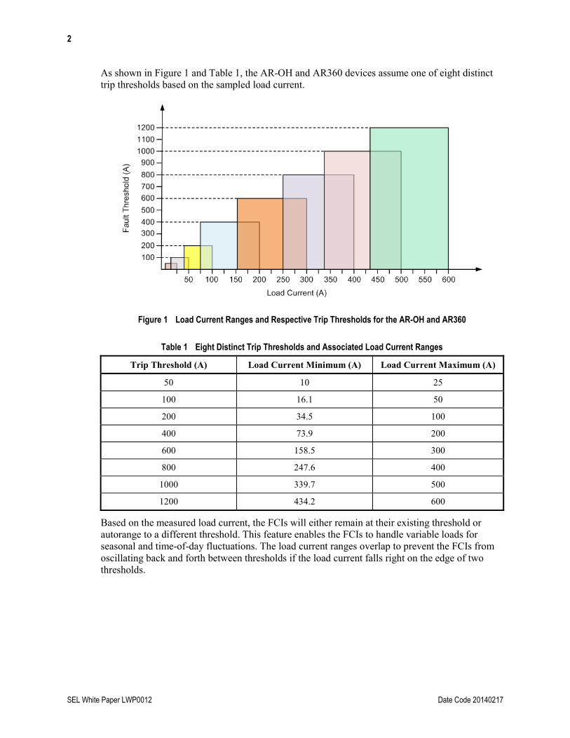
As shown in Figure 1 and Table 1, the AR-OH and AR360 devices assume one of eight distinct trip thresholds based on the sampled load current.
Figure 1 Load Current Ranges and Respective Trip Thresholds for the AR-OH and AR360
Table 1 Eight Distinct Trip Thresholds and Associated Load Current Ranges
Trip Threshold (A) Load Current Minimum (A) Load Current Maximum (A)
50 10 25
100 16.1 50
200 34.5 100
400 73.9 200
600 158.5 300
800 247.6 400
1000 339.7 500
1200 434.2 600
Based on the measured load current, the FCIs will either remain at their existing threshold or autorange to a different threshold. This feature enables the FCIs to handle variable loads for seasonal and time-of-day fluctuations. The load current ranges overlap to prevent the FCIs from oscillating back and forth between thresholds if the load current falls right on the edge of two thresholds.
3
Date Code 20140217 SEL White Paper LWP0012
INSTALLATION The AR-OH and AR360 fault indicators are single hot stick installable by a single lineman. The FCIs are applicable on nonshielded and noninsulated bare conductors that have outer cable diameters ranging from 0.162 to 1.5 inches. Installing these FCIs on insulated conductors can affect their voltage-sensing capability. Consult SEL regarding insulated conductor applications. The AR360 has a system voltage range of 4.16 to 34.5 kV line-to-line, and the AR-OH has a system voltage range of 4.16 to 69 kV line-to-line. Figure 2 and Figure 3 show proper application of the AR-OH and AR360, respectively, on a bare conductor.
Figure 2 Installation of the AR-OH
21 3Spring Clamp
Conductor
Retaining Bar
Figure 3 Installation of the AR360
The indicators must be placed at least 2 feet away from any energized hardware in order to ensure optimum voltage-sensing capability. It is also recommended that the indicators be placed at least 3 feet but no more than 6 feet away from the pole, as shown in Figure 4.
Figure 4 Placement of FCIs on Overhead Lines
FAULT INDICATION MODES The AR-OH and AR360 have the ability to distinguish between momentary and permanent faults. Any overcurrent condition that is sustained for more than 24 milliseconds above the self-configured fault threshold will cause the FCIs to display a permanent fault. Two minutes after the
4
SEL White Paper LWP0012 Date Code 20140217
fault, the FCIs will check for system voltage and current. The FCIs will register the overcurrent event as one of the following:
Load pickup event. If the overcurrent condition is actually a new higher sustained load, the indicator will stop flashing a permanent fault sequence and self-adjust to the appropriate trip threshold.
Momentary fault event. An energized circuit with nominal current after the 2-minute period signifies a self-clearing fault or a successful trip and reclose operation. The FCIs will enter the momentary fault mode and begin flashing the momentary fault sequence.
Permanent fault event. A de-energized circuit after the 2-minute period signifies that a circuit lockout has occurred. The FCIs will enter the permanent fault mode and continue flashing the permanent fault sequence.
FCIs in the momentary fault mode reset anytime the circuit is de-energized. This ensures that a new fault is given priority over an older, momentary fault.
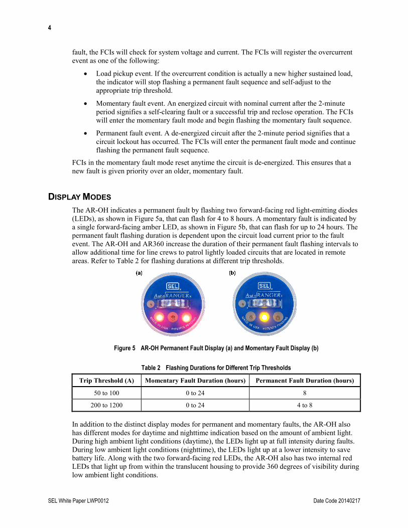
DISPLAY MODES The AR-OH indicates a permanent fault by flashing two forward-facing red light-emitting diodes (LEDs), as shown in Figure 5a, that can flash for 4 to 8 hours. A momentary fault is indicated by a single forward-facing amber LED, as shown in Figure 5b, that can flash for up to 24 hours. The permanent fault flashing duration is dependent upon the circuit load current prior to the fault event. The AR-OH and AR360 increase the duration of their permanent fault flashing intervals to allow additional time for line crews to patrol lightly loaded circuits that are located in remote areas. Refer to Table 2 for flashing durations at different trip thresholds.
In addition to the distinct display modes for permanent and momentary faults, the AR-OH also has different modes for daytime and nighttime indication based on the amount of ambient light. During high ambient light conditions (daytime), the LEDs light up at full intensity during faults. During low ambient light conditions (nighttime), the LEDs light up at a lower intensity to save battery life. Along with the two forward-facing red LEDs, the AR-OH also has two internal red LEDs that light up from within the translucent housing to provide 360 degrees of visibility during low ambient light conditions.
5
Date Code 20140217 SEL White Paper LWP0012
The AR360 has six high-intensity, wide-angle LEDs that provide overlapping fields of light around the hexagonal face for a 360-degree display, as shown in Figure 6. During a permanent fault, the AR360 flashes three red and three amber LEDs in a rotating sequence for 4 to 8 hours. During a momentary fault, the AR360 flashes three amber LEDs in a blinking pattern for up to 24 hours.
PRINCIPLES OF OPERATION The AR-OH and AR360 are equipped with several built-in features that help ensure the accurate and reliable indication of faults.
Trip Response Time
The AR-OH and AR360 have a nominal trip response time of 24 milliseconds. During production testing, the units must not trip when given a 1-cycle (16.6-millisecond) trip pulse. However, the units must trip when given a 2-cycle (33.3-millisecond) trip pulse. This delayed trip response time reduces the chance of tripping from high-frequency current spikes from backfeed sources, such as capacitor banks. The trip response time of 24 milliseconds is also based on 150 percent of the trip current threshold.
Ramp-Down Restraint®
The AR-OH and AR360 implement a Ramp-Down Restraint algorithm that prevents the FCIs from selecting a lower trip value when the circuit is locked out. The FCIs will not autorange down if they detect less than 10 amperes or if they do not sense voltage for more than 5 minutes.
Inrush Restraint
Fault indicators on nonfaulted phases should be immune to inrush currents when applied on circuits that use reclosing schemes. During reclose attempts, the energization of the conductors can create inrush currents that exceed fault current levels on nonfaulted phases. FCIs without IR logic can falsely trip because of reclosing events. To prevent this, the AR-OH and AR360 identify when system protection operates by monitoring for a loss of system current (less than 10 amperes) or voltage (less than 2.4 kV line-to-ground) lasting 3 to 6 cycles (50 to 100 milliseconds). When either the current or voltage drops below these thresholds, the FCIs will enter IR lockout mode and not respond to any events for a lockout period of 3 minutes. After 3 minutes, the FCIs need to detect continuous current (greater than 10 amperes) for 2 minutes or voltage (greater than 2.4 kV line-to-ground) for 5 minutes if there is less than 10 amperes of current. After detecting continuous power, the AR-OH and AR360 are armed and ready to trip for future events.
6
SEL White Paper LWP0012 Date Code 20140217
In the example shown in Figure 7, the FCI sees inrush current above its trip threshold during the reclosing attempts but does not falsely trip in IR lockout mode. After sensing continuous current for 2 minutes, the FCI is armed and ready to respond to faults.
Figure 7 Example FCI Response
Battery Conservation
The AR-OH and AR360 are designed to provide optimum battery conservation to ensure years of maintenance-free service. The AR-OH is powered by a nonreplaceable, 8.5 Ah lithium size C cell, and the AR360 is powered by a 17 Ah lithium battery (two C cells). Table 3 depicts the expected flashing hours for the AR360. The number of flashing hours becomes an important factor when comparing LED or strobe-type fault indicators. The AR360 is equipped with a nonreplaceable battery that provides a minimum of 2,000 flashing hours for typical applications. The battery life ensures that the device is maintenance-free for more than 10 years. This results in a lower cost of ownership when compared with solutions that require multiple battery replacements over the same 10-year period.
Table 3 Expected Flashing Hours for AR360
Fault Mode Light Mode Flash Hours Number of Events
in 10 Years
Frequency (1 Event Every
n Days)
Permanent Day 550 137 (4 hours) 26
Permanent Night 1500 375 (4 hours) 9
Momentary Day 2700 337 (8 hours) 10
Momentary Night 7400 925 (8 hours) 4
Hybrid Hybrid 2000 285 (7 hours) 12
The hybrid calculation (1) is based on the assumption that the AR360-4-8 unit is used and that 75 percent of events are momentary, 25 percent are permanent, 50 percent occur during the day, and 50 percent occur at night. This calculation also assumes a 2 percent yearly degradation of the battery at an ambient temperature of 25°C plus a 25 percent battery derating.
3 3 1 1
momentary day momentary night permanent day permanent night8 8 8 8
(1)
7
Date Code 20140217 SEL White Paper LWP0012
Reset and Test
The AR-OH and AR360 are timed reset FCIs. Timed reset prevents units from falsely resetting due to backfeed voltages and/or currents. The CRSRTT tool can be used to manually reset the FCIs instead of waiting for their time-out periods to end. The tool can also be used for field testing to verify the operational functionality and the battery life of the FCIs. Both manual reset and test activation modes are activated by closing the contact of an internal reed switch via a magnetic field from the CRSRTT tool, as shown in Figure 8.
Figure 8 Test Activation for AR-OH (a) and AR360 (b)
The FCIs flash in a test sequence when activated with the test tool. For the AR-OH test sequence, the red LEDs repeat several three-flash sequences and the amber LED repeats several two-flash sequences. For the AR360, the red and amber LEDs repeat the permanent fault sequence for 40 seconds, the amber LEDs repeat single-flash sequences for 20 seconds, and the unit turns off automatically.
CONCLUSION The AR-OH and AR360 fault indicators lead the way in overhead fault indication and meet the needs of end users that require local indication of faults on overhead distribution lines. With the ability to automatically adjust their trip thresholds and distinguish between momentary and permanent fault events, the AR-OH and AR360 fault indicators help find faults more efficiently and lessen outage times when applied at strategic locations. SEL fault indicators and sensors provide an excellent solution for finding and locating faults in order to improve total system reliability.
8
SEL White Paper LWP0012 Date Code 20140217
BIOGRAPHIES Tyson Salewske is the southwest regional sales and service director for Schweitzer Engineering Laboratories, Inc. (SEL). Prior to this role, he was a business development manager, where he promoted SEL solutions to stakeholders in commercial and institutional markets. Tyson also spent four years as a field application engineer for the SEL fault indicator and sensor division and six years at ZIV USA, a Spanish protective relaying manufacturer, as a sales and applications engineer. He received his BSEE from Iowa State University and MBA from Lake Forest Graduate School of Management. Tyson is a senior member of IEEE.
Anthony Patenaude is an associate field application engineer for the fault indicator and sensor division of Schweitzer Engineering Laboratories, Inc. (SEL). He received his BSEE from Purdue University in West Lafayette, Indiana, and has participated in a cooperative learning program for 2 years as an electrical reliability engineer for CITGO Petroleum in Lemont, Illinois. Anthony is also an active member of IEEE.
All brand or product names appearing in this document are the trademark or registered trademark of their respective holders. No SEL trademarks may be used without written permission.
SEL products appearing in this document may be covered by US and foreign patents.