Functional safety and reliability for innovative vehicle braking system and integration with electric traction units T. Favilli, M. Delogu, L. Pugi and L. Berzi Universit` a degli Studi di Firenze, Department of Industrial Engineerring (DIEF), Firenze 50129, IT E-mail: [email protected]Abstract. Newly electric vehicle architectures require intensive virtual and physical testing for safety assessment, due to the increasing relevance of By-Wire systems and the presence of innovative control algorithms for ordinary driving scenario, potential emergency situations or Advanced Driver-Assistance Systems implementation purpose. To reduce the development time while increasing system reliability and the a priori knowledge about its safety requirements, the evaluation of such aspects should be performed. In accordance to ISO26262 standard, authors propose a systematic approach based on Virtual FMEA, in order to assess the functional safety level of hybrid brake plant. Plant modification and securing strategy as been presented and implemented in target vehicle model, evaluating their performances in simulation environments, in order to met required Automotive Safety Integrity Level. This work is developed in the ambit of OBELICS European Project. 1. Introduction Nowadays, the usage of embedded controller devices in the electric automotive field is further increasing, thanks to the introduction of By-Wire (BW) systems [1, 2, 3]. Also, interaction between users and Electric/Electronic (E/E) systems on board are more frequent, since are becoming more and more active, including drive prediction and Advanced Driver-Assistance Systems (ADAS). The growing complexity of such plants, due to the integration of more functionalities and the attribution of safety-related tasks (relieved from the pilot) can lead both to increased fault probability and severity. It’s also interesting to notice that in a scenario in which autonomous and assisted driving functionalities are implemented, reliability of underlying automation and actuation systems hast to be further increased, considering the limited awareness of human driver when dealing with complex nested automation layers. Those faults are quite difficult to be correctly interpreted, especially when low-mid level control layers are affected. Reliability and Safety are crucial factors for the correct operation of a product, especially for E/E devices adopted in the automotive sector, whose developments process must follow rigorous procedures. Indeed, essential drive functionalities are implemented trough Control Unit (CU), so safety-critical active system should be developed in accordance to severe functional reliability concept. Standard ISO 26262 [4] provide useful guidelines, assisting designer through all main phases of the V-shape procedure, in order to develop a product which respects required safety performances. Occurrences of faults during operative phases of an E/E systems of Electric
Transcript
Functional safety and reliability for innovative vehicle
braking system and integration with electric traction
units
T. Favilli, M. Delogu, L. Pugi and L. Berzi
Universita degli Studi di Firenze, Department of Industrial Engineerring (DIEF), Firenze50129, IT
Abstract. Newly electric vehicle architectures require intensive virtual and physical testingfor safety assessment, due to the increasing relevance of By-Wire systems and the presence ofinnovative control algorithms for ordinary driving scenario, potential emergency situations orAdvanced Driver-Assistance Systems implementation purpose. To reduce the development timewhile increasing system reliability and the a priori knowledge about its safety requirements, theevaluation of such aspects should be performed. In accordance to ISO26262 standard, authorspropose a systematic approach based on Virtual FMEA, in order to assess the functional safetylevel of hybrid brake plant. Plant modification and securing strategy as been presented andimplemented in target vehicle model, evaluating their performances in simulation environments,in order to met required Automotive Safety Integrity Level. This work is developed in the ambitof OBELICS European Project.
1. IntroductionNowadays, the usage of embedded controller devices in the electric automotive field is furtherincreasing, thanks to the introduction of By-Wire (BW) systems [1, 2, 3]. Also, interactionbetween users and Electric/Electronic (E/E) systems on board are more frequent, since arebecoming more and more active, including drive prediction and Advanced Driver-AssistanceSystems (ADAS). The growing complexity of such plants, due to the integration of morefunctionalities and the attribution of safety-related tasks (relieved from the pilot) can lead bothto increased fault probability and severity. It’s also interesting to notice that in a scenario inwhich autonomous and assisted driving functionalities are implemented, reliability of underlyingautomation and actuation systems hast to be further increased, considering the limited awarenessof human driver when dealing with complex nested automation layers. Those faults are quitedifficult to be correctly interpreted, especially when low-mid level control layers are affected.
Reliability and Safety are crucial factors for the correct operation of a product, especially forE/E devices adopted in the automotive sector, whose developments process must follow rigorousprocedures. Indeed, essential drive functionalities are implemented trough Control Unit (CU),so safety-critical active system should be developed in accordance to severe functional reliabilityconcept. Standard ISO 26262 [4] provide useful guidelines, assisting designer through all mainphases of the V-shape procedure, in order to develop a product which respects required safetyperformances. Occurrences of faults during operative phases of an E/E systems of Electric
Vehicle (EV)s, can lead to a deviation from the expected behaviour, with potential risk forthe users, especially for those systems dealing with active safety functionalities. So, it isrecommended to analyze the fault-modes of the involved devices, to avoid undesired effectin the overall system reliability, using a Virtual Failure Mode and Effect Analysis (vFMEA)approach. More in detail, relevant examples of BW commands on latest generation vehicles are:throttle, braking and steer. All of them are fundamental for vehicle safety and controllability.Literature experience describe main design criteria for such applications, including appropriatesystem topology, and the testing procedures needed to quantify their functional reliability, faulttolerance and applicability on road vehicles [5, 6]. In this context, ISO2626 provides a solidframework for system development which is applicable to x-by-wire analysis, possibly integratedwith modeling activities [7, 8, 9, 10, 11, 12].
These aspects highlight the importance of ensuring enhanced reliability and safetyperformances for these systems. To avoid these situations, a systematic procedure for thedesign, development and validation of automotive systems could be a feasible solution to avoid adangerous and harmful scenario. The supposed failure mechanisms, determined trough FailureMode and Effect Analysis (FMEA), are related to the vehicle Electronic Control Unit (ECU).Faults are supposed permanent (irreversible) and concern hardware and interaction failure.However, proposed solution are effective also for transient and intermittent failures. Such failuresare always possible due to the aggressive and dangerous environment of automotive applicationsand the growing complexity of hardware components and system architecture. The investigationfocuses on the proposal of a virtual simulation environment, implemented with a model-basedapproach, to assess the consequences of a fault on the vehicle behaviour, through Fault Injection(FI) simulations activities on a vehicle model and related sub-systems.
Proposed methodology, which is developed in the ambit of the Optimization of scalaBlerEaltime modeLs and functIonal testing for e-drive ConceptS (OBELICS) European Project(under Horizon2020), similarly to other performance assessment procedures described inliterature [13, 14], concern EV functional safety concept and aims at the safety assessmentof investigated brake plant. However, respect to the actual State-of-Arts (SoA), this solutionis developed in accordance with ISO 26262 standard’s specifications, which strongly suggest tosupport the validation protocol with FI techniques. In particular, a multi-level FI approach isadopted, which consists in the simulation of investigated failure modes, useful to establish theireffects on the vehicle behaviour. The proposed approach allows the validation, tolerance andrecovery from a fault condition of the product’s functionalities. Depending on the developmentphase of the vehicle, two different approaches are selected: In an early phase, starting from thefailure rate of single components, the potential combined failure are calculated using Montecarloapproach with simplified models, in order to find out main interactions within componentlayout; In a second phase, vehicle system topology is reproduced in a Multiphysics simulationenvironment and the certain faults events (e.g. those highlighted as critical by previous steps)are injected in the system. Such approach is aimed to verify the consequences of the failureitself and develop and verify the functionality of mitigation strategies. Looking at modelconcept, the approach suggests the modification of typical “model identity cards” adding portssuitable to represent component state-of-function, which can be expressed either as Boolean orprogressive variability of performances (e.g. 0 to 100 functionality); in practice, this means thatparameters usually adopted to represent component static characteristics are modified as tunableparameters or even as variables. This allows to dynamically change component functionalityduring simulation itself. The case study presented – a 4 Wheel Drive (4WD) concept EV – hasbeen used to estimate stopping distance with regular and degraded components; in particular, aparameter strongly influencing the results is the time delay needed for failure recognition, whichdepends partly on physical construction partly on software decisions (e.g. number of failureconfirmation events needed to avoid false positives): in this way, the model can be adopted not
only to verify the effectiveness of mitigation strategies, but also for pre-calculate the time-delaythat vehicle designer should adopt as target, to prevent the occurrence of dangerous events, thusbeing also a tool to better set up vehicle specifications and, thus, reducing development time.
The current activities propose the definition of a systematic methodology based on vFMEAapproach and ISO 26262 standard specifications to evaluate and assess the actual and targetAutomotive Safety Integrity Level (ASIL) for the investigated brake functionalities related tocomplex vehicle architecture, due to the growing relevance of active stability ECUs and BWsystems. This study aim at identify the major weakness of the brake plant and establish properarchitecture modification or control strategy to fit the previously determined safety requirement.Results will reduce man-hour and cost of the Brake By-Wire (BBW) reliability analysis.
2. Proposed MethodologyThe purpose of this activity concerns different aspects: ensuring braking performances of theEV and the BBW system reliability, as well as the availability of safety-related functionalitiesin which brake is involved, despite the operation of the various subsystems dealing with brakeeffort management (Electronic Braking Distributor (EBD), Anti-lock Braking System (ABS),Electronic Stability Program (ESP) or Automatic Emergency Braking (AEB)) and application(Brake Blending (BB)). At this purpose, while reducing time and cost effort, authors define asystematic model-based methodology, to implement vFMEA and FI analysis.
Developed reliability analysis solution consists of different phases:
(i) SoA investigation: an in-depth literature review is conducted, to identify the failure rateand distribution of the brake component.
(ii) FMEA: Failure Modes and Effects Analysis is executed on the target BBW components.This step aims to identify failure mode, causes and consequences of involved components.FMEA constitutes an essential methodology in the development process of a product,allowing reliable forecast and letting designer focus on most critical plant parts, assistingthem in the application of the securing mechanism that should be implemented to fulfilminimum safety requirements.
(iii) ISO 26262 guidelines application: guidelines of the standards have been applied tothe reference brake system, in order to evaluate target and actual ASIL, respect to theinvestigated plant functionalities.
(iv) Simulation-based FI: performed in a virtual simulation environment. This consist in theexecution of controlled tests, where the behaviour of the EV is observed when one or morefaults are triggered [15, 16]. In particular, FI is used to evaluate if the response of the systemfulfils the specification when faults occur. ISO 26262 strongly recommends this procedureas a supporting tool to develop fault removal and prevention tasks. Also, the standardencourages the application of multi-level FI, redefining specific solution to increase systemreliability and functional safety, to be applied during the whole development process. In thiswork, a double-level FI approach is used. Firstly, it is applied in the early stages of design,on a high-level abstracted model, to establish the most significant faults. Then, simulationsare repeated on a more sophisticated model (developed in MATLAB Simulink), to evaluatethe appropriateness of the supposed boundary condition, coherence with previous resultsand effectiveness of proposed securing solutions.
(v) Securing Solutions: finally, plant modification and securing strategy are proposed andimplemented in the Simulink environment, to better understand the impact of them inbrake system reliability and performance.
For a better understanding of the approach adopted in this activity, a flowchart of theproposed methodology is visible in Figure 1. Once the benchmark vehicle is chosen, physical andfunctional scheme of the corresponding BBW system is identified. Failure rates and probabilitydistributions of the brake plant components are identified during the SoA review. Then, proceedwith the analysis of the causes, modes and effects of the investigated faults.
This phase is fundamental in order to select most critical malfuncionalities and proposesecuring solutions. At this point, guidelines of ISO 26262 standard are applied to establishtarget ASIL and the FI simulation activities performed, to assess the plant reliability aspect,respect to specific functionalities. If the target ASIL is reached, the process ends: it can be statethat the system fulfills standard specifications; otherwise, appropriate securing mechanisms areimplemented in the vehicle models and simulations repeated, to confirm their effectiveness.
FMEA and FI techniques show strong similarities and share several common goals. Mostrelevant concerns the identification of the critical system faults. This purpose can be achievedby analyzing causes and effects trough FMEA process and observing their impact using FI. Also,both aim at the definition of those subsystems which require a securing mechanism, specificallyaddressed for diagnostic and mitigation of failures.
Figure 1. Flowchart of the proposed methodology
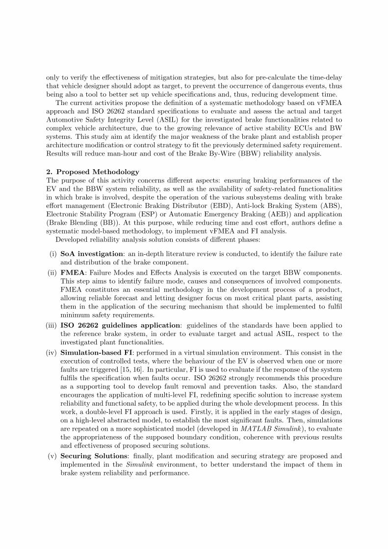
3. Benchmark Electric VehicleThe procedure described in the previous section is applied to a reference Use Case (UC),represented in Figure 2. Investigated EV is a fully electric concept car developed by Valeo,equipped with 4 independent In-Wheel Motor (IWM)s. Main parameters of the benchmarkvehicle are summarized in Table 1.
The investigated system involves several mechanical, electrical and electronic sub-components, belonging to different physical domains. Considering the following layout of Figure3, based on a functional analysis of the scheme proposed in [17, 18, 19, 20], is possible to identifythe following elements:
• Brake Pedal Interface: pedal position command is translated in a brake demand that istransferred to an Electronic Brake Control;
• Electronic Brake Control: It’s an underlying automation layer which produces an actuationreference according to brake demand, vehicle dynamics and other connected autonomoussystems, implementing also active safety functionalities (EBD, ABS, ESP);
• Wheel Brake Control Unit: brake reference is actuated on the wheel, regardless of whateverthe torque is applied by disc or electric motor. It includes Motor Control Unit (MCU) andBB controller.
• Electric Vehicle equipment: consisting of all the sub-systems of the vehicle, e.g. battery,Battery Management System (BMS), inverter, Electric Motor (EM), hydraulic brake plant.
Figure 2. Benchmark EV
This consideration allows a concept abstraction respect to the considered vehicle layout,to propose a flexible methodology which can effectively be applied to different powertrainarchitectures and UCs, allowing man-hour and cost reduction, thanks to the possibility toautomatically adapt the proposed approach to several EV’s e-powertrain and brake systemconfigurations.
The layout of Figure 3 is applicable. However, it should be considered the integration of amultiple braking actuation, in which the mechanical brake system is integrated with the electricone. This makes of the Battery Electric Vehicle (BEV) an over-actuated system from the brakingfunctionalities aspects, offering opportunities to achieve increased ASIL, due to the redundancyof the brake plant. Indeed, enhanced brake plant reliability could be reached by the applicationof innovative BB strategies and the proposal of specific procedures for the vehicle securing,implemented thought control algorithms.
It is considered the integration in the system of a BB strategy, using the EV architecturerepresented in Figure 4: since each wheel has its independent braking and traction control unit,the brake blending system is integrated at the level of a single wheel. This is an example oflower-level integration which assures a higher level of redundancy, since the BB ECU failureaffects only one wheel. On the other hand, specific securing procedures have to be implemented,to avoid undesired vehicle dynamics behaviour, such possible yaw moment generated by thedifferential braking between right and left tires.
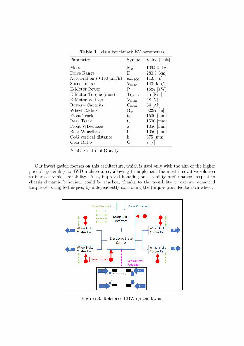
Table 1. Main benchmark EV parameters
Parameter Symbol Value [Unit]
Mass Mv 1094.4 [kg]Drive Range Dr 280.8 [km]Acceleration (0-100 km/h) a0−100 11.96 [s]Speed (max) Vmax 140 [km/h]E-Motor Power P 15x4 [kW]E-Motor Torque (max) Tqmax 55 [Nm]E-Motor Voltage Vnom 48 [V]Battery Capacity Cnom 64 [Ah]Wheel Radius Rw 0.292 [m]Front Track tf 1500 [mm]Rear Track tr 1500 [mm]Front Wheelbase a 1056 [mm]Rear Wheelbase b 1056 [mm]CoG vertical distance h 375 [mm]Gear Ratio Gr 8 [/]
*CoG: Centre of Gravity
Our investigation focuses on this architecture, which is used only with the aim of the higherpossible generality to 4WD architectures, allowing to implement the most innovative solutionto increase vehicle reliability. Also, improved handling and stability performances respect tochassis dynamic behaviour could be reached, thanks to the possibility to execute advancedtorque vectoring techniques, by independently controlling the torques provided to each wheel.
Figure 3. Reference BBW system layout
Figure 4. Reference BBW system layout with BB
3.1. State-of-Art reviewFor this kind of generic BBW system, there are some sources in literature to be considered:works of Sinha et al. [22] simply introduce an analysis of the level of redundancy and reliabilityof ECUs and communication bus, to ensure the overall reliability requirements of the brakingsystem. Respect to the investigated BBW plant layout of Figure 4, a preliminary SoA review isperformed to find the appropriate fault distribution and Mean Time Between Failure (MTBF)for each of the brake system component.
Despite some tech data-sheet from Original Equipment Manufacturer (OEM)s suggest abathtub rate distribution (e.g. Texas Instrument), authors suppose to consider only componentsin the fit region. So, the adoption a uniform distribution for the CUs is assumed, using themaximum value of failure rate of the fit region, which are summarized in Table 2.
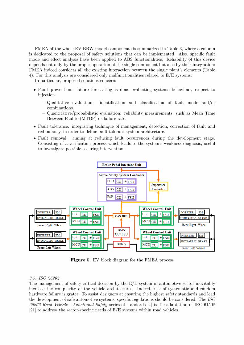
3.2. Failure Mode and Effect AnalysisFMEA is a bottom-up failure identification systematic process, applied to the EV layout ofFigure 4. It consist of several stages: plant decomposition in independent unit, identification offunctionalities and interconnections between sub-systems and definition of modes and effects ofthe faults for each unit. This risk analysis is essential in order to identify major weakness of theBBW plant, letting designer to focus mainly on most critical elements and define appropriatesecuring strategy. FMEA methodology appear versatile and flexible, concerning single elementor whole system faults. Output of this phase is the EV layout block diagram of Figure 5. It isassumed the presence of an additional CU, the Supervisor Controller, which superintends at thethe securing strategy funcionalities.
Table 2. Failure rate of different components used in our analysis
Component Failure Rate λ[1/h]
Pedal sensor 1 · 10−7
Wheel speed sensor 1 · 10−7
Pressure sensor 5.69 · 10−7
ECU 5.88 · 10−7
Wires 1 · 10−9
CAN bus 2.58 · 10−9
Battery 2 · 10−6
Inverter 3.77 · 10−7
FMEA of the whole EV BBW model components is summarized in Table 3, where a columnis dedicated to the proposal of safety solutions that can be implemented. Also, specific faultmode and effect analysis have been applied to ABS functionalities. Reliability of this devicedepends not only by the proper operation of the single component but also by their integration:FMEA indeed considers all the existing interaction between the single plant’s elements (Table4). For this analysis are considered only malfunctionalities related to E/E systems.
In particular, proposed solutions concern:
• Fault prevention: failure forecasting is done evaluating systems behaviour, respect toinjection.
– Qualitative evaluation: identification and classification of fault mode and/orcombinations.
– Quantitative/probabilistic evaluation: reliability measurements, such as Mean TimeBetween Faulite (MTBF) or failure rate.
• Fault tolerance: integrating technique of management, detection, correction of fault andredundancy, in order to define fault-tolerant system architecture.
• Fault removal: aiming at reducing fault occurrences during the development stage.Consisting of a verification process which leads to the system’s weakness diagnosis, usefulto investigate possible securing intervention.
Figure 5. EV block diagram for the FMEA process
3.3. ISO 26262The management of safety-critical decision by the E/E system in automotive sector inevitablyincrease the complexity of the vehicle architectures. Indeed, risk of systematic and randomhardware failure is grater. To assist designers at ensuring the highest safety standards and leadthe development of safe automotive systems, specific regulations should be considered. The ISO26262 Road Vehicle - Functional Safety series of standards [4] is the adaptation of IEC 61508[21] to address the sector-specific needs of E/E systems within road vehicles.
Wrong diagnostic Software fault Warning lightWrong signal Software fault
RPN: Risk Priority Number
This adaptation applies to all activities during the safety life-cycle of safety-related systems,comprised of electrical, electronic and software components. It provides methods and techniqueswhich should be integrated into the development process to ensure the required functional safetylevel of E/E devices in road vehicles. In particular, it stats the necessity to assist traditionalreliability assessment solutions, e.g. FMEA, Failure Mode, Effect and Criticality Analysis(FMECA), Fault Tree Analysis (FTA) or Block Reliability Diagram (BRD) with FI strategy.ASIL of a specific fault modality can be determined through 3 parameters and its values rangingfrom QM (minimum) to D (maximum). ISO 26262 assist developers in the definition of Severity,Exposure and Controllability.
Severity is related to the level of risk for the users resulting from the fault occurrence. Thisvalue is established using the Abbreviated Injury Scale (AIS), developed by the Association forthe Advancement of Automotive Medicine. Respect to these values, the standard provides adirect correspondence with a new scale ranging from S0 (min) to S3 (max).
Exposure is strictly dependant from the probability to be in a specific driving scenario, inwhich the fault could occur. All the operative condition should be considered, e.g. road condition
and typology, weather condition or performed manoeuvres. In this work, both the table proposedby IEC 61508 and ISO 26262 are considered. Exposure value range from E0 (incredible) to E4(high probability).
Controllability replicate the concepts of fault detection and reaction, indicating which amountof common driver (expressed in percentage) can manage and handle the considered fault event,in order to avert or minimize the extent of risk. Even in this case, the standard proposes acorresponding table, with values ranging from C0 (controllable in general) to C3 (less than 90%of drivers can handle the harm situation). This parameters could be mitigated by appropriatereports to the driver and diagnostic procedures (e.g. warning light on the dashboard).
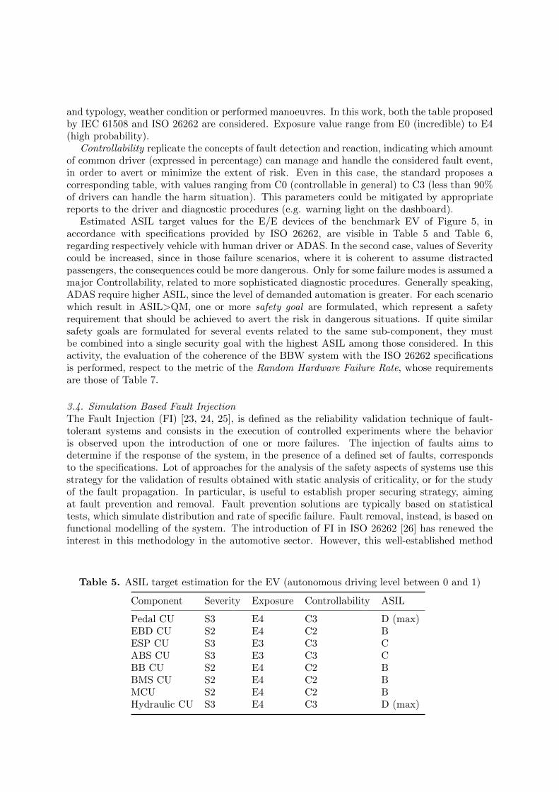
Estimated ASIL target values for the E/E devices of the benchmark EV of Figure 5, inaccordance with specifications provided by ISO 26262, are visible in Table 5 and Table 6,regarding respectively vehicle with human driver or ADAS. In the second case, values of Severitycould be increased, since in those failure scenarios, where it is coherent to assume distractedpassengers, the consequences could be more dangerous. Only for some failure modes is assumed amajor Controllability, related to more sophisticated diagnostic procedures. Generally speaking,ADAS require higher ASIL, since the level of demanded automation is greater. For each scenariowhich result in ASIL>QM, one or more safety goal are formulated, which represent a safetyrequirement that should be achieved to avert the risk in dangerous situations. If quite similarsafety goals are formulated for several events related to the same sub-component, they mustbe combined into a single security goal with the highest ASIL among those considered. In thisactivity, the evaluation of the coherence of the BBW system with the ISO 26262 specificationsis performed, respect to the metric of the Random Hardware Failure Rate, whose requirementsare those of Table 7.
3.4. Simulation Based Fault InjectionThe Fault Injection (FI) [23, 24, 25], is defined as the reliability validation technique of fault-tolerant systems and consists in the execution of controlled experiments where the behavioris observed upon the introduction of one or more failures. The injection of faults aims todetermine if the response of the system, in the presence of a defined set of faults, correspondsto the specifications. Lot of approaches for the analysis of the safety aspects of systems use thisstrategy for the validation of results obtained with static analysis of criticality, or for the studyof the fault propagation. In particular, is useful to establish proper securing strategy, aimingat fault prevention and removal. Fault prevention solutions are typically based on statisticaltests, which simulate distribution and rate of specific failure. Fault removal, instead, is based onfunctional modelling of the system. The introduction of FI in ISO 26262 [26] has renewed theinterest in this methodology in the automotive sector. However, this well-established method
Table 5. ASIL target estimation for the EV (autonomous driving level between 0 and 1)
Component Severity Exposure Controllability ASIL
Pedal CU S3 E4 C3 D (max)EBD CU S2 E4 C2 BESP CU S3 E3 C3 CABS CU S3 E3 C3 CBB CU S2 E4 C2 BBMS CU S2 E4 C2 BMCU S2 E4 C2 BHydraulic CU S3 E4 C3 D (max)
Table 6. ASIL target estimation for the EV (autonomous driving level greater than 2)
Component Severity Exposure Controllability ASIL
Pedal CU S3 E3 C2 BEBD CU S3 E4 C2 CESP CU S3 E3 C2 BABS CU S3 E3 C3 CBB CU S2 E4 C2 BBMS CU S2 E4 C2 BMCU S2 E4 C2 BHydraulic CU S3 E4 C3 D (max)
Table 7. ASIL target respect to Random Hardware Failure Rate
ASIL Failure Rate λ[1/h]
B < 10−7
C < 10−7
D < 10−8
of verification is now used in different sectors. The standard motivated the adoption of newlysolutions for the safety assessment of a product, redefining specific reliability concepts whichshould be applied during development phases, supporting conventional failure analysis methods.In particular, strongly recommend the usage of simulation-based FI techniques on model with ahigh level of physical abstraction, in order to identify errors in safety requirements managementand propose appropriate securing strategy.
Developed simulation test campaigns consist of two different steps. In the first phase arecursive Montecarlo simulation campaign of a simplified vehicle model (high level ofphysical abstraction) is performed at high computational speed, considering the real value ofcomponent’s fault occurrences and probability distributions. The impact of several brake systemfailure modes in the vehicle stopping distance is evaluated, resulting in a quite similar reliableoutput. High integrity and safety levels of the brake system are involved to embed the currentmechatronic system within a higher-level system, related to autonomous or assisted braking. Inthis stage, which components of the plant are more inclined to failure and/or had the majorimpact of vehicle braking performances can be established. A better understanding of thoseaspects allows the proposal of efficient and robust securing policies for fault prevention, whichcould be a useful tool for the achievement of target ASIL.
Then, once establish from the latter phase a specific number of dangerous scenarios respect tofunctional safety, Model-based simulation campaign of specific failure events are repeatedusing a more precise accurate vehicle model, from physical and functional point of view.This allows evaluating the appropriateness of the proposed approach and securing solutions,comparing result obtained at this stage and in the previous one and proposing fault removalsolutions. Also,it consent to better identify causes and effects of failure, improving the knowledgeof the mechanism of their occurrence and related impact on functional safety, used even to furtherincrease the accuracy of the Montecarlo FI model. In both cases, the simulation environmentinvolves 2 sub-models: Target system, which is the vehicle model; FI controller, consisting of aFault Injector, which contains the vectors of possible fault and schedule their onset; the FaultMonitor, which detects malfunctions and communicates with the Supervisor controller.
It is important to note that a delay is considered between the fault occurrences and itsdetection (Figure 6). This delay replicates the physiological lag of the communication channels(e.g. flooding of the CAN bus system) and time step interval (of 50 ms). Additional 300 mstime-out is supposed, in order to avoid false positive fault detection by the Supervisor controller,whose monitor the failure occurrences, turns on the warning light in the driver dashboard andtriggers specific securing algorithms to start failure mitigation procedures.
Figure 6. Supposed delay between fault occurrences and confirmation
The reason behind the choice of this process is mainly referred to the necessity of reducingthe simulation computational effort and time. vFMEA activities require the execution of billionrecursive simulations to observe failure event, which are in the magnitude of 10−7 − 10−8
occurrences per hour. So, it is necessary to identify the system weakness in a shorter timeand lower energy/cost consuming, in the optics of implementing fault mitigation solutions inthe early phases of system and components design, evaluating also their effectiveness respect tofunctional safety requirements.
Concerning the specification given by the OBELICS project, developed model has thefollowing characteristics:
• Numerical efficient : able to perform a large number of simulations, considering severalcombinations of faults and performances degradation in different operational conditionsand scenarios. Real-Time (RT) implementation is required;
• Simple and standardized : models flexibility is ensured by proper scalability and portabilityproperties, in order to be easily portable for different vehicle architecture and layout,as well as for different simulation environments and boundary conditions. Modelsare parametrized and modular, letting further modification in order to fit other UCsarchitecture’s specifications;
• Robust and reliable: respect to the physical abstraction, which in some cases can lead tocomplex dynamic behaviour that introduces further integration problems, especially whena fault occur.
3.4.1. Montecarlo Simulation. In this phase, each component of the investigated BBW systemis abstracted by its primary functionality and considered as a simplified element [27], identifiedonly by its own MTBF and fault distribution. Probability of fault occurrences is estimatedfrom SoA, literature investigation, component and system data-sheet and proper technicalconsiderations [16, 22, 28].
This abstraction concept, based on system BRD, is useful to implement an efficient andeffective Montecarlo recursive study, aimed to establish the stopping distance of the vehicle whenone or more component of the brake system experience fault situations. This probabilistic-basedimplementation, from the computational effort perspective, is designed to perform 103 − 1012
consecutive iteration, using a simple functional approach devoted to parallel computing (parallelpool and coded functions supported by MATLAB). This type of simulation is also suitable fornumerically intensive implementation of GPU hardware, an ideal application for Hardware inthe Loop (HiL) test method.
The Montecarlo simulation campaign is based on the vehicle dynamic equation, according tothe simplified formula of the stopping distance calculation related to a braking manoeuvre (1):
s =v202a
+ v0d (1)
Where s is the stopping distance expressed in meter, v0 the initial vehicle speed in meter persecond, a the acceleration in meter per square second and d the time delay in seconds.
The output of this test campaigns constitutes a preliminary supporting tool for the followingmodel-based FI: the information arising from the Montecarlo simulations allows understandingthe system weakness and to identify the specific plant components which mainly experience fails.At this point, it is possible to deeply study the select scenario, by their implementation in amore sophisticated simulation environment.
Considered fault event could be of 2 different types:
• Boolean Fault: the component can appear as completely healthy (ON) or dead (OFF).When a fault condition occur its functionalities are considered lost;
• Derating Fault: the component can be partially available, and its functionalities reduced inthe magnitude order of a percentage.
3.4.2. Model-based Simulation. A more complete vehicle equipment model is implemented inthe Simulink environment [17, 18, 19, 20] to assess the effect of the BBW E/E devices failureon the car vehicle behaviour. These models were previously developed in the ambit of theOBELICS activities. For this work, however, models have been modified to account fault effectby the introduction of FI controller, which allows supposing specific component failure.
The detailed FI model, developed in MATLAB Simulink environment (Figure 7), is designedfor 100 − 103 iterative simulations and it is useful to evaluate the consequence of a fault or tovalidate expected results on a worst-case scenario, established in the previous step. This fullvehicle equipment functional model consists in several sub-systems, belonging to quite differentphysical domains:
• Driver: which ensures the coherence with the reference manoeuvres through differentProportional Integrative Derivative (PID) controllers, respectively for traction, braking andsteer commands.
• Vehicle Chassis: a 7 Degree of Freedom (DoF) model, consisting of many sub-systems, i.e.steering model (with Ackermann layout); 3 DoF body model in longitudinal, lateral andyaw directions; wheel models, which consider the tire-road interaction in accordance toPacejka pure longitudinal slip equation [29], adding 1 DoF each.
• Torque Regulation Controller: comprising EBD, useful to ensure optimal front/rear torquesallocation respect to longitudinal load transfer; ESP, for the lateral vehicle stability, basedon hierarchical Moore-Penrose pseudo-inverse solution [20]; ABS and Anti-Slip Regulation(ASR) controllers, used to maintain wheel slips in proper bandwidth, during braking andtraction phases; BB controller, which dispatches braking efforts to EM and hydraulic plantin function of the e-powertrain power availability.
• Torque Actuation: composed by the e-powertrain model (BMS, energy storage system,MCU and EM), replicating the ideal power-torque motor characteristics, and the hydraulicbrake plant functional decomposition model [30].
• Monitor: to check the contollers status and to observe the vehicle dynamic behaviour whenone or more faults occur.
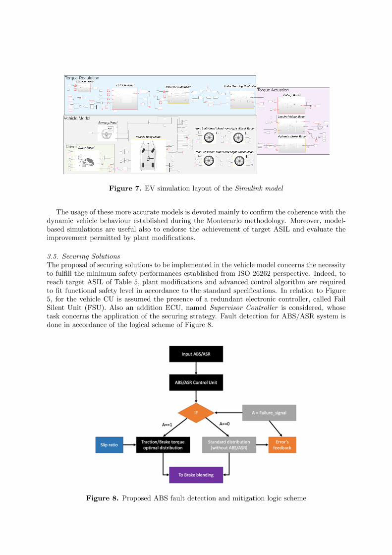
Figure 7. EV simulation layout of the Simulink model
The usage of these more accurate models is devoted mainly to confirm the coherence with thedynamic vehicle behaviour established during the Montecarlo methodology. Moreover, model-based simulations are useful also to endorse the achievement of target ASIL and evaluate theimprovement permitted by plant modifications.
3.5. Securing SolutionsThe proposal of securing solutions to be implemented in the vehicle model concerns the necessityto fulfill the minimum safety performances established from ISO 26262 perspective. Indeed, toreach target ASIL of Table 5, plant modifications and advanced control algorithm are requiredto fit functional safety level in accordance to the standard specifications. In relation to Figure5, for the vehicle CU is assumed the presence of a redundant electronic controller, called FailSilent Unit (FSU). Also an addition ECU, named Supervisor Controller is considered, whosetask concerns the application of the securing strategy. Fault detection for ABS/ASR system isdone in accordance of the logical scheme of Figure 8.
Figure 8. Proposed ABS fault detection and mitigation logic scheme
When slip is above admitted value and the comparison between torque command, arisingfrom upstream controllers, and output demanded signals is negligible, the fault is detectedand confirmed after the time out interval, by turning on the warning light and bypassing ABSfunctionalities [15]. Other securing strategy, summarized in Table 4, are realized in analogy withthis one.
4. Results and DiscussionsIn this section are summarized the result concerning the FI simulation campaign, obtained fromthe application of the proposed methodology to the benchmark EV, supposing different faults.Also, is assumes a specific fault of the CU related to anti-lock braking functionalities, whosesimplified scheme is represented in Figure 9, in which are evident the interconnection withinother BBW components. It is important to know that the proposed Supervisor Controlleris able to perform diagnostic functions, turning off ABS system when errors are detected.This implemented securing strategy allows the application of braking torque to wheels, which,however, are not modulated to keep the slip in the admitted bandwidth.
Figure 9. ABS funcional decomposition scheme
For the purpose of this simulation campaigns, the boundary condition of the simulated testsis the one provided by ISO 21994:2007 [31]. This standard is related to the determination of thestopping distance in Straight line deceleration with ABS in open-loop test methodology, whichshould remain under 40 m for braking manoeuvres on good surface, starting from an initialspeed of 100 km/h.
Figure 10. Investigated reference manoeuvres
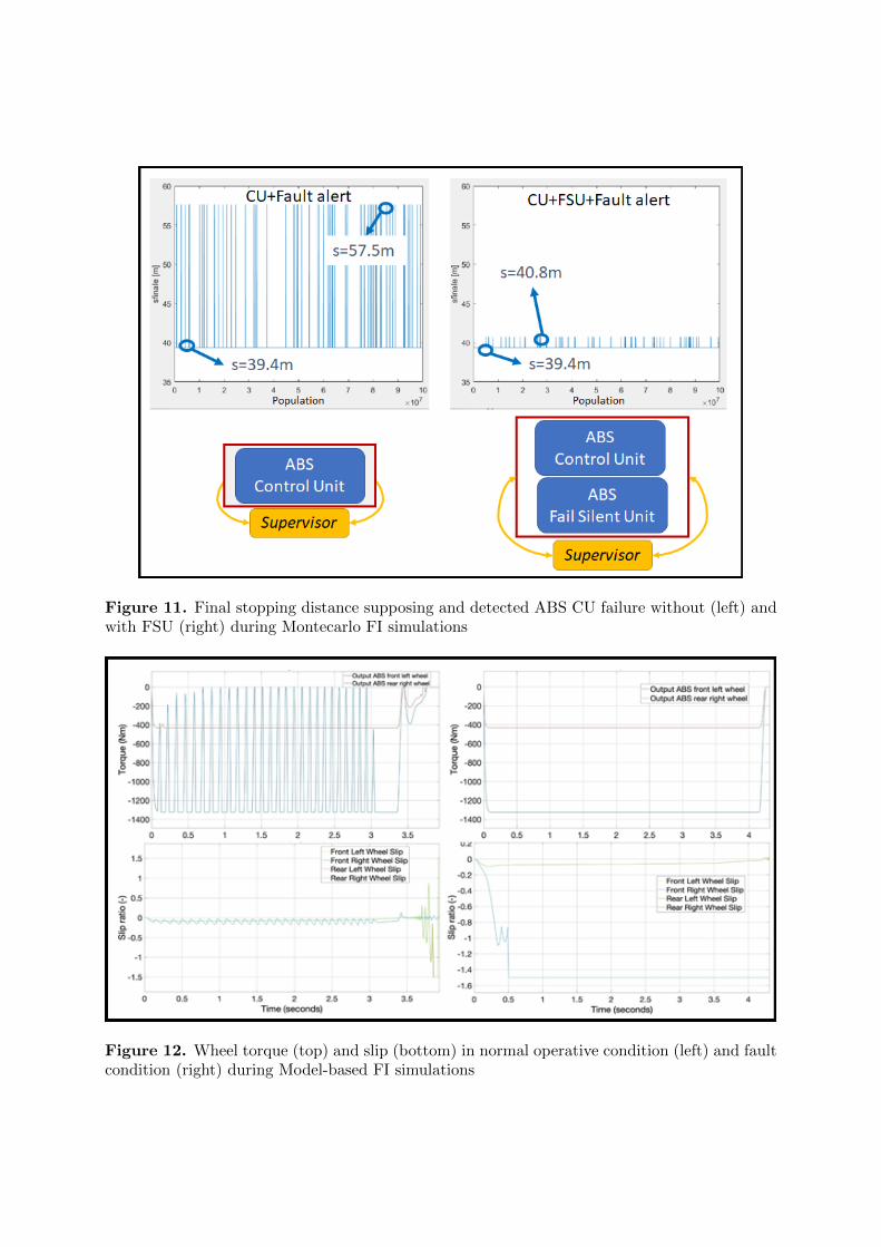
4.1. Montecarlo Simulation Campaign ResultsIn this kind of tests, different failures are supposed, whose specifications, respect to the BBWsystem layout of Figure 5, are summarized in Table 8, along with some parametric variable,useful to simulate different braking conditions (e.g. vehicle mass variation). For the E/E controlunits a redundant solution with FSU is suggested. This consideration is due to the high ASILrequired. Results of the tests are in agreement with these assumptions, since the detection ofthe failure will result in acceptable stopping distance.
Consider the simulation results of Figure 11, which refers to the fault of ABS CU for apopulation of 100 millions of straight line deceleration event. These outcomes correspond toabout 72 billion of operative hours of the brake system. This fact is due to that executed testsconsider the failure rates of Table 8, which are expressed in terms of occurrences per hour, butthe reference manoeuvre only lasts about 5 seconds, so between the rates there is a factor of720, according to (2).
λ[1/h] = λ[1/3600s] = λ[1/5s] · 1
720(2)
Table 8. Investigated failure in the Montecarlo simulation campaign
Sub-sytem Failure Rate λ [1/h] Distribution Parameters
In particular, Figure 11 shows how an additional control unit, the FSU, markedly improvesbraking performance, thanks to the presence of the redundant backup controller, which replacesthe primary electronic regulator after the time-out (once fault is confirmed). In the caseof a single CU instead, the intervention of the Supervisor Controller is needed, applyingcorresponding securing strategy.
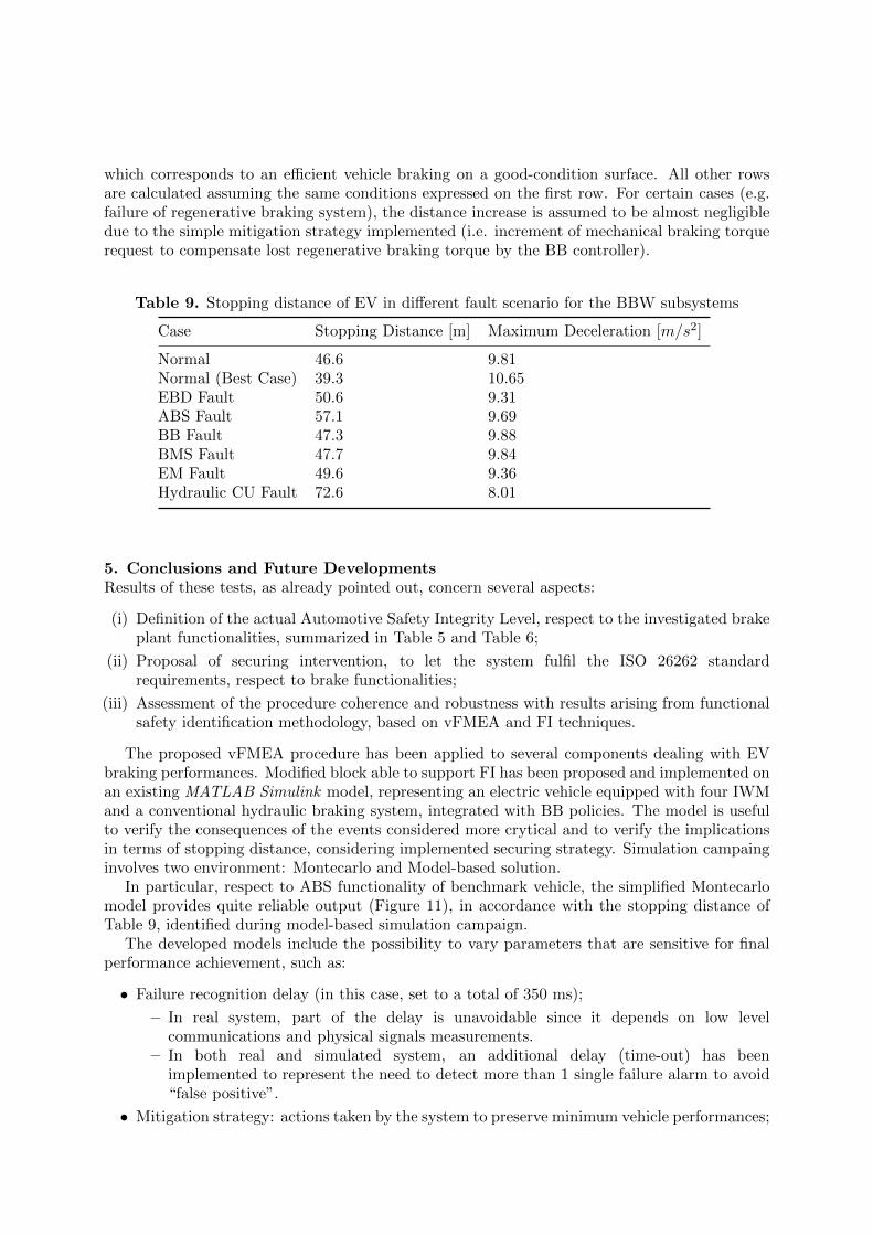
4.2. Model-based FI Campaign ResultsThe braking manoeuvre [31] is repeated for the full vehicle model, supposing the fault occurrencesof all the subsystems dealing with braking performances and BBW functionalities. In the model-based simulation are investigated the effect on vehicle behaviour of the securing strategy.
Output of Figure 12 shows wheel torques and slips in normal operative condition (left) andABS control unit fault (right). In the second case the Supervisor Controller applies the securingsolution of Figure 8. So, even in the extremely rare case of simultaneous failure of CU and FSU,is still possible to apply braking torques to the wheels. However, these ones are not properlymodulated, so wheel loking occurs, resulting in an increased stopping distance (Table 9).
Making the vehicle replicate, for each investigated faults dealing with braking performances,the same manoeuvre allows to comparatively evaluate the effect on stopping distance related tothe different fault mode and sub-systems. Stopping distances are visible in Table 9. Please notethat the first two rows of the table refer to the full working vehicle stopping condition; the firstone presents a stopping distance of 46.6m , which corresponds to an efficient vehicle brakingon a medium-condition surface; while the second one presents a stopping distance of 39.3m,
Figure 11. Final stopping distance supposing and detected ABS CU failure without (left) andwith FSU (right) during Montecarlo FI simulations
Figure 12. Wheel torque (top) and slip (bottom) in normal operative condition (left) and faultcondition (right) during Model-based FI simulations
which corresponds to an efficient vehicle braking on a good-condition surface. All other rowsare calculated assuming the same conditions expressed on the first row. For certain cases (e.g.failure of regenerative braking system), the distance increase is assumed to be almost negligibledue to the simple mitigation strategy implemented (i.e. increment of mechanical braking torquerequest to compensate lost regenerative braking torque by the BB controller).
Table 9. Stopping distance of EV in different fault scenario for the BBW subsystems
Case Stopping Distance [m] Maximum Deceleration [m/s2]
5. Conclusions and Future DevelopmentsResults of these tests, as already pointed out, concern several aspects:
(i) Definition of the actual Automotive Safety Integrity Level, respect to the investigated brakeplant functionalities, summarized in Table 5 and Table 6;
(ii) Proposal of securing intervention, to let the system fulfil the ISO 26262 standardrequirements, respect to brake functionalities;
(iii) Assessment of the procedure coherence and robustness with results arising from functionalsafety identification methodology, based on vFMEA and FI techniques.
The proposed vFMEA procedure has been applied to several components dealing with EVbraking performances. Modified block able to support FI has been proposed and implemented onan existing MATLAB Simulink model, representing an electric vehicle equipped with four IWMand a conventional hydraulic braking system, integrated with BB policies. The model is usefulto verify the consequences of the events considered more crytical and to verify the implicationsin terms of stopping distance, considering implemented securing strategy. Simulation campainginvolves two environment: Montecarlo and Model-based solution.
In particular, respect to ABS functionality of benchmark vehicle, the simplified Montecarlomodel provides quite reliable output (Figure 11), in accordance with the stopping distance ofTable 9, identified during model-based simulation campaign.
The developed models include the possibility to vary parameters that are sensitive for finalperformance achievement, such as:
• Failure recognition delay (in this case, set to a total of 350 ms);
– In real system, part of the delay is unavoidable since it depends on low levelcommunications and physical signals measurements.
– In both real and simulated system, an additional delay (time-out) has beenimplemented to represent the need to detect more than 1 single failure alarm to avoid“false positive”.
• Mitigation strategy: actions taken by the system to preserve minimum vehicle performances;
– Very simple strategies, when possible, have been defined (e.g. brake blendingmodification in case of total of partial loss of regenerative braking torque).
The model is defined on the basis of “high level” representation, so real system topologyis not reproduced. Typical examples are: redundant can-bus communication, here representedthrough the aggregated failure probability, based on BRD, but not through two data linesmodeling; double microprocessor for operator + Supervisor Controller. Also, the inclusion ofdelay and “false positive” mitigation strategy are built in order to simplify implementation onembedded system taking into account the risk of communication limitations (e.g. CAN busflooding) thus avoiding excessive data transmission rates on the communication lines.
In conclusion it can be stated that:
• A tool for the reliability assessment of a target Brake-By-Wire system has been developed,trough systematic Virtual Fault Mode and Effect Analysis methodology;
• Proposed solution, in accordance with ISO 26262 standard, adopts Fault Injectiontechnique, applied on vehicle models with different level of detail, in order to let usersscale the methodology, according to number and accuracy of desired results;
• Applied to the reference vehicle UC ABS system, allowed verifying the effectiveness ofproposed securing solution (redundancy of E/E, application of fault mitigation strategy),making investigated system fulfill standard specifications respect to the random hardwarefailure metric (Table 7), which is in the order of 10−12 [1/h].
Possible future developments concern:
• The automation of the process, trough the definition of modular library of fault and itsvariables;
• The extension of the study to other system and component of the automotive sector;
• The assessment of target ASIL respect to other evaluation metrics, e.g. Diagnostic Coverage,Single Point Fault, Latent Fault.
AcknowledgmentsThis project has received funding from the European Union’s Horizon 2020 research andinnovation program under grant agreement No 769506. The information and views set outin this publication does not necessarily reflect the official opinion of the European Commission.Neither the European Union institutions and bodies nor any person acting on their behalf, maybe held responsible for the use which may be made of the information contained therein.
References[1] Martin H., Krammer M., Winkler B. and Schwarzl C. 2015 Model-based Engineering Workflow for
Automotive Safety Concepts p 0273 doi: 10.4271/2015-01-0273[2] Yu L., Liu X., Xie Z. and Chen Y. 2016 Review of Brake-by-Wire System Used in Modern Passenger Car
18th International Conference on Advanced Vehicle Technologies; 13th International Conference on DesignEducation vol 3 American Society of Mechanical Engineers (Charlotte North Carolina, USA)
[3] Martin H., Tschabuschnig K., Bridal O. and Watzenig D. 2017 Functional Safety of Automated DrivingSystems: Does ISO 26262 Meet the Challenges? Automated Driving: Safer and More Efficient FutureDriving D. Watzenig, E. M. Horn and A. c. d. Cham, Eds., Springer
[4] International Electrotechnical Commission IEC 2018 ISO-26262 Road Vehicle – Functional Safety part 1-12[5] Huang, C. Naghdy, F. Du, H., Huang, H., 2019. Fault tolerant steer-by-wire systems: An overview. Annual
Reviews in Control 47, 98–111. https://doi.org/10.1016/j.arcontrol.2019.04.001[6] Zulkifli, S.A., Asirvadam, V.S., Saad, N., Aziz, A.R.A., Mohideen, A.A.M. 2014 Implementation of
electronic throttle-by-wire for a hybrid electric vehicle using National Instruments’ CompactRIO andLabVIEW Real-Time, 2014 5th International Conference on Intelligent and Advanced Systems (ICIAS).Presented at the 2014 5th International Conference on Intelligent and Advanced Systems (ICIAS), pp. 1–6.https://doi.org/10.1109/ICIAS.2014.6869555
[7] Kafka, P., 2012 The Automotive Standard ISO 26262, the Innovative Driver for Enhanced Safety Assessmentand Technology for Motor Cars. Procedia Engineering, 2012 International Symposium on Safety Scienceand Technology 45, 2–10. https://doi.org/10.1016/j.proeng.2012.08.112
[8] Kwon, H., Itabashi-Campbell, R., McLaughlin, K., 2013 ISO 26262 application to electric steeringdevelopment with a focus on Hazard Analysis, 2013 IEEE International Systems Conference(SysCon). Presented at the 2013 IEEE International Systems Conference (SysCon), pp. 655–661.https://doi.org/10.1109/SysCon.2013.6549952
[9] Lidstrom, C., Bondesson, C., Nyberg, M., Westman, J., 2019. Improved Pattern for ISO 26262ASIL Decomposition with Dependent Requirements 2019 IEEE 19th International Conference onSoftware Quality, Reliability and Security Companion (QRS-C). Presented at the 2019 IEEE 19thInternational Conference on Software Quality, Reliability and Security Companion (QRS-C), pp. 28–35.https://doi.org/10.1109/QRS-C.2019.00019
[10] Leu K-L., Huang H., Chen Y-Y., Huang L-R. and Ji K-M. 2015 An intelligent brake-by-wire system designand analysis in accordance with ISO-26262 functional safety standard. 2015 International Conference onConnected Vehicles and Expo (ICCVE) [Internet]. Shenzhen, China: IEEE; 2015 [cited 2020 Sep 9]. p.150–6. Available from: http://ieeexplore.ieee.org/document/7447585/
[11] Bernon-Enjalbert V., Blazy-Winning M., Gubian R., Lopez D., Meunier J-P and O’Donnell M. Safety-Integrated Hardware Solutions to Support ASIL-D Applications.
[12] Hasegawa M. and Kaneko T. 2016 Examination of Hazard Analysis and Risk Assessment and ExposureResearch in the Real Traffic Situation of ISO 26262 for Motorcycles SAE Int J Passeng Cars – ElectronElectr Syst 2016 Nov 8;10(1):95–101.
[13] Nakao S., Shimozawa M., Sugure Y. 2014 Virtual FMEA: Simulation-Based ECU Electrical Failure Modeand Effects Analysis p. 2014-01–0205. Available from: https://www.sae.org/content/2014-01-0205/
[14] Nakao S., Hyodo A., Itabashi M., Sakashita T., Obara S., Uno T., et al. 2017 Virtual FMEA and ItsApplication to Software Verification of Electric Power Steering System. p. 2017-01–0066. Available from:https://www.sae.org/content/2017-01-0066/
[15] Rana R., Staron M., Berger C., Hansson J., Nilsson M. and Torner F. 2013 Improving Fault Injection inAutomotive Model Based Development using Fault Bypass Modeling Informatik angepasst an Mensch,Organisation und Umwelt
[16] Zhang J., Zhang Y. and Li G. 2018 Functional Safety Design of Four-Wheel Independent Brake System onElectric Vehicle IOP Conf Ser: Earth Environ Sci. Jul;170:042071
[17] Pugi L Favilli T Berzi L Locorotondo E and Pierini M 2019 Brake Blending and Optimal Torque AllocationStrategies for Innovative Electric Powertrains Saponara S, De Gloria A, editors. Applications in ElectronicsPervading Industry, Environment and Society [Internet]. Cham: Springer International Publishing p.477–83 Available from: http://link.springer.com/10.1007/978 − 3 − 030 − 11973 − 757
[18] Pugi L., Favilli T., Berzi L., Locorotondo E. and Pierini M. 2019 Application of Regenerative Braking onElectric Vehicles 2019 IEEE International Conference on Environment and Electrical Engineering and2019 IEEE Industrial and Commercial Power Systems Europe (EEEIC / ICPS Europe) (Genova, Italy)p. 1–6 Available from: https://ieeexplore.ieee.org/document/8783318/
[20] Pugi L., Favilli T., Berzi L., Locorotondo E. and Pierini M. 2020 Brake blending and torque vectoring ofroad electric vehicles: a flexible approach based on smart torque allocation. IJEHV
[21] International Electrotechnical Commission IEC 2010 IEC-61508, Functional safety of electric/ electronic/programmable safety-related systems (Geneva)
[22] Sinha P. 2011 Architectural design and reliability analysis of a fail-operational brake-by-wire system fromISO 26262 perspectives Reliability Engineering System Safety Oct96(10):1349–59
[23] Ziade H., Ayoubi R. and Velazco R. 2004 A Survey on Fault Injection Techniques. 2004;1(2):16.[24] Kooli M. and Di Natale G. A survey on simulation-based fault injection tools for complex systems.
2014 9th IEEE International Conference on Design Technology of Integrated Systems in NanoscaleEra (DTIS) [Internet] Santorini, Greece: IEEE; 2014 [cited 2020 Sep 9]. p. 1–6. Available from:http://ieeexplore.ieee.org/document/6850649/
[25] Mei-Chen H., Tsai TK., Iyer RK. 1997 Fault injection techniques and tools. Computer. pr;30(4):75–82.[26] Pintard L., Fabre J-C., Kanoun K., Leeman M. and, Roy M. 2013 Fault Injection in the Automotive Standard
ISO 26262: An Initial Approach Vieira M, Cunha JC, editors. Dependable Computing [Internet] Berlin,Heidelberg: Springer Berlin Heidelberg; 2013 [cited 2020 Sep 9]. p. 126–33. (Hutchison D, Kanade T,Kittler J, Kleinberg JM, Mattern F, Mitchell JC, et al., editors. Lecture Notes in Computer Science; vol.
7869) Available from: http://link.springer.com/10.1007/978-3-642-38789-011[27] Malvezzi M., Presciani P., Allotta B. and Toni P. 2003 Probabilistic analysis of braking performance in
railways Proceedings of the Institution of Mechanical Engineers, Part F: Journal of Rail and Rapid Transit217(3):149–65
[28] Linzey G. 1996 Development of the Electrical Wiring Interconnection System Risk Assessment Tool U.S.Department of Transportation Federal Aviation Administration
[29] Pacejka H.2005 Tire and Vehicle Dynamics Elsevier 657 p.[30] D’hondt T., Forrier B., Sarrazin M., Favilli T., Pugi L., Berzi L., et al. Modeling and Identification of an
Electric Vehicle Braking System: Thermal and Tribology Phenomena Assessment 2020 p.2020-01–1094Available from: https://www.sae.org/content/2020-01-1094/
[31] Technical Committee ISO/TC 22/SC 33 Vehicle dynamics and chassis components ISO 21994:2007 Passengercars — Stopping distance at straight-line braking with ABS — Open-loop test method