SD00347P/00/EN/01.11 71143291 Functional Safety Manual Cerabar M PMC51, PMP51/55 Deltabar M PMD55 Deltapilot M FMB50/51/52/53 Process pressure / Differential pressure, Flow / Hydrostatic Deltapilot M Deltabar M Cerabar M Application Operating minimum, maximum and range monitoring of gases, vapours and liquids in systems to satisfy particular safety systems requirements as per IEC 61508 Edition 2.0 and IEC 61511. The measuring device fulfils the requirements concerning • Functional safety as per IEC 61508 Edition 2.0 and IEC 61511 • Explosion protection (depending on the version) • Electromagnetic compatibility as per EN 61326 and NAMUR recommendation NE 21 • Electrical safety as per IEC/EN 61010-1 Your benefits • Used for pressure, level and flow monitoring (MIN, MAX, Range) up to SIL 2 – Independently assessed and certified by TÜV NORD CERT as per IEC 61508 Edition 2.0 and IEC 61511 • Permanent self-monitoring • Continuous measurement • Easy commissioning
Transcript
SD00347P/00/EN/01.11
71143291
Functional Safety Manual
Cerabar M PMC51, PMP51/55Deltabar M PMD55Deltapilot M FMB50/51/52/53Process pressure / Differential pressure, Flow / Hydrostatic
Deltapilot M
Deltabar M
Cerabar M
Application
Operating minimum, maximum and range monitoring
of gases, vapours and liquids in systems to satisfy
particular safety systems requirements as per IEC 61508
Edition 2.0 and IEC 61511.
The measuring device fulfils the requirements
concerning
• Functional safety as per IEC 61508 Edition 2.0 and
IEC 61511
• Explosion protection (depending on the version)
• Electromagnetic compatibility as per EN 61326 and
NAMUR recommendation NE 21
• Electrical safety as per IEC/EN 61010-1
Your benefits
• Used for pressure, level and flow monitoring
(MIN, MAX, Range) up to SIL 2
– Independently assessed and certified by
TÜV NORD CERT as per IEC 61508 Edition 2.0
and IEC 61511
• Permanent self-monitoring
• Continuous measurement
• Easy commissioning
Cerabar M, Deltabar M, Deltapilot M
2 Endress+Hauser
Table of contents
SIL Declaration of Conformity - Cerabar M . . . . . . . . . 3
SIL Declaration of Conformity - Deltabar M. . . . . . . . . 4
SIL Declaration of Conformity - Deltapilot M. . . . . . . . 5
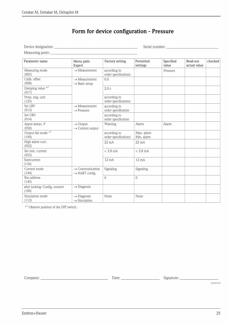
Form for device configuration - Pressure. . . . . . . . . . 25
Form for device configuration - Level . . . . . . . . . . . . 26
Form for device configuration - Flow. . . . . . . . . . . . . 27
Cerabar M, Deltabar M, Deltapilot M
Endress+Hauser 3
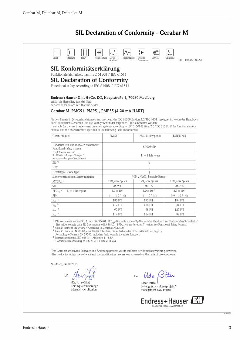
SIL Declaration of Conformity - Cerabar M
sil_11044a
1)
2)
3)
Die Werte entsprechen SIL 2 nach ISA S84.01. PFD -Werte für andere T -Werte siehe Handbuch zur Funktionalen Sicherheit./The values comply with SIL 2 according to ISA S84.01. PFD values for other T -values see Functional Safety Manual.Gemäß Siemens SN 29500 / According to
avg 1
avg 1
Siemens SN 29500Gemäß Siemens SN 29500, einschließlich Fehlern, die außerhalb der Sicherheitsfunktion liegen./According to Siemens SN 29500, including faults outside the safety function.Betrachtung gemäß IEC 61511-1 Abschnitt 11.4.4./Consideration according to IEC 61511-1 clause 11.4.4.
4)
Maulburg, 30.08.2011
Cerabar M PMP51, PMP55 (4-20 mA HART)PMC51,
SIL-11044a/00/A2
SIL-Konformitätserklärung
SIL Declaration of ConformityFunktionale Sicherheit nach IEC 61508 / IEC 61511
/ IEC 61511Functional safety according to IEC 61508
Endress+Hauser GmbH+Co. KG, Hauptstraße 1, 79689 Maulburgerklärt als Hersteller, dass das Gerätdeclares as manufacturer, that the device
für den Einsatz in Schutzeinrichtungen entsprechend der IEC 61508 Edition 2.0/IEC 61511 geeignet ist, wenn das Handbuchzur Funktionalen Sicherheit und die Kenngrößen in der folgenden Tabelle beachtet werden:is suitable for the use in safety-instrumented systems according to IEC 61508 Edition 2.0/IEC 61511, if the functional safetymanual and the characteristics specified in the following table are observed:
Gerät/Product
Handbuch zur Funktionalen Sicherheit/Functional safety manual
SIL
HFT
Gerätetyp/Device type
SFF
PFD * T = 1 Jahr/year
PFH
4)
tot3)
Sicherheitsfunktion/Safety function
MTBF
avg1
1
sd
dd
du
2)
su2)
2)
2)
�
�
�
�
SD00347P
2
0
B
PMC51
MIN , MAX , Bereich/Range
129 Jahre/years
5.0 10
85.9 %
1.1 10 1/h
193 FIT
412 FIT
92 FIT
114 FIT
-4
-7
�
�
139
4.3 10
Jahre/years
86.7 %
9.9 10 1/h
194 FIT
334 FIT
120 FIT
99 FIT
-4
-8
�
�
PMC51 (Hygiene)
i.V.
(Dr. Arno Götz)Leitung Zertifizierung/Manager Certification
Das Gerät einschließlich Software und Änderungsprozess wurde auf Basis der Betriebsbewährung bewertet.The device including the software and the modification process was assessed on the basis of proven-in-use.
i.V.
( )Udo GrittkeLeitung Entwicklungsprojekt/Management R&D Projekt
Empfohlenes Intervallfür Wiederholungsprüfungen/recommended proof test interval
T = 1 Jahr/year1
PMP51/55
129
5.0 10
Jahre/years
86.1 %
1.1 10 1/h
193 FIT
418 FIT
98 FIT
114 FIT
-4
-7
�
�
Cerabar M, Deltabar M, Deltapilot M
4 Endress+Hauser
SIL Declaration of Conformity - Deltabar M
sil_11045a
1)
2)
3)
Die Werte entsprechen SIL 2 nach ISA S84.01. PFD -Werte für andere T -Werte siehe Handbuch zur Funktionalen Sicherheit./The values comply with SIL 2 according to ISA S84.01. PFD values for other T -values see Functional Safety Manual.Gemäß Siemens SN 29500 / According to
avg 1
avg 1
Siemens SN 29500Gemäß Siemens SN 29500, einschließlich Fehlern, die außerhalb der Sicherheitsfunktion liegen./According to Siemens SN 29500, including faults outside the safety function.Betrachtung gemäß IEC 61511-1 Abschnitt 11.4.4./Consideration according to IEC 61511-1 clause 11.4.4.
4)
Maulburg, 30.08.2011
Deltabar M PMD55 (4-20 mA HART)
SIL-11045a/00/A2
SIL-Konformitätserklärung
SIL Declaration of ConformityFunktionale Sicherheit nach IEC 61508 / IEC 61511
/ IEC 61511Functional safety according to IEC 61508
Endress+Hauser GmbH+Co. KG, Hauptstraße 1, 79689 Maulburgerklärt als Hersteller, dass das Gerätdeclares as manufacturer, that the device
für den Einsatz in Schutzeinrichtungen entsprechend der IEC 61508 Edition 2.0/IEC 61511 geeignet ist, wenn das Handbuchzur Funktionalen Sicherheit und die Kenngrößen in der folgenden Tabelle beachtet werden:is suitable for the use in safety-instrumented systems according to IEC 61508 Edition 2.0/IEC 61511, if the functional safetymanual and the characteristics specified in the following table are observed:
Gerät/Product
Handbuch zur Funktionalen Sicherheit/Functional safety manual
SIL
HFT
Gerätetyp/Device type
SFF
PFD * T = 1 Jahr/year
PFH
4)
tot3)
Sicherheitsfunktion/Safety function
MTBF
avg1
1
sd
dd
du
2)
su2)
2)
2)
�
�
�
�
SD00347P
2
0
B
PMD55
MIN , MAX , Bereich/Range
159 Jahre/years
80
5.6 10
.1 %
1.3 10 1/h
194 FIT
203 FIT
120 FIT
128 FIT
-4
-7
�
�
i.V.
(Dr. Arno Götz)Leitung Zertifizierung/Manager Certification
Das Gerät einschließlich Software und Änderungsprozess wurde auf Basis der Betriebsbewährung bewertet.The device including the software and the modification process was assessed on the basis of proven-in-use.
i.V.
( )Udo GrittkeLeitung Entwicklungsprojekt/Management R&D Projekt
Empfohlenes Intervallfür Wiederholungsprüfungen/recommended proof test interval
T = 1 Jahr/year1
Cerabar M, Deltabar M, Deltapilot M
Endress+Hauser 5
SIL Declaration of Conformity - Deltapilot M
sil_11046a
1)
2)
3)
Die Werte entsprechen SIL 2 nach ISA S84.01. PFD -Werte für andere T -Werte siehe Handbuch zur Funktionalen Sicherheit./The values comply with SIL 2 according to ISA S84.01. PFD values for other T -values see Functional Safety Manual.Gemäß Siemens SN 29500 / According to
avg 1
avg 1
Siemens SN 29500Gemäß Siemens SN 29500, einschließlich Fehlern, die außerhalb der Sicherheitsfunktion liegen./According to Siemens SN 29500, including faults outside the safety function.Betrachtung gemäß IEC 61511-1 Abschnitt 11.4.4./Consideration according to IEC 61511-1 clause 11.4.4.
4)
Maulburg, 30.08.2011
Deltapilot M FMB50, FMB51, FMB52, FMB53 (4-20 mA HART)
SIL-11046a/00/A2
SIL-Konformitätserklärung
SIL Declaration of ConformityFunktionale Sicherheit nach IEC 61508 / IEC 61511
/ IEC 61511Functional safety according to IEC 61508
Endress+Hauser GmbH+Co. KG, Hauptstraße 1, 79689 Maulburgerklärt als Hersteller, dass das Gerätdeclares as manufacturer, that the device
für den Einsatz in Schutzeinrichtungen entsprechend der IEC 61508 Edition 2.0/IEC 61511 geeignet ist, wenn das Handbuchzur Funktionalen Sicherheit und die Kenngrößen in der folgenden Tabelle beachtet werden:is suitable for the use in safety-instrumented systems according to IEC 61508 Edition 2.0/IEC 61511, if the functional safetymanual and the characteristics specified in the following table are observed:
Gerät/Product
Handbuch zur Funktionalen Sicherheit/Functional safety manual
SIL
HFT
Gerätetyp/Device type
SFF
PFD * T = 1 Jahr/year
PFH
4)
tot3)
Sicherheitsfunktion/Safety function
MTBF
avg1
1
sd
dd
du
2)
su2)
2)
2)
�
�
�
�
SD00347P
2
0
B
FMB50(kompakt / compact)
MIN , MAX , Bereich/Range
140 Jahre/years
4.3 10
86.6 %
9.9 10 1/h
194 FIT
330 FIT
118 FIT
99 FIT
-4
-8
�
�
95
1.0 10
Jahre/years
79.4 %
2.3 10 1/h
292 FIT
466 FIT
138 FIT
231 FIT
-3
-7
�
�
FMB51/52/53(Stab/Seil / rod/cable)
i.V.
(Dr. Arno Götz)Leitung Zertifizierung/Manager Certification
Das Gerät einschließlich Software und Änderungsprozess wurde auf Basis der Betriebsbewährung bewertet.The device including the software and the modification process was assessed on the basis of proven-in-use.
i.V.
( )Udo GrittkeLeitung Entwicklungsprojekt/Management R&D Projekt
Empfohlenes Intervallfür Wiederholungsprüfungen/recommended proof test interval
T = 1 Jahr/year1
Cerabar M, Deltabar M, Deltapilot M
6 Endress+Hauser
Introduction
! Note!
General information on functional safety (SIL) is available at:
www.de.endress.com/SIL (German) or www.endress.com/SIL (English) and in Competence Brochure
CP002Z "Functional Safety in the Process Industry - Risk Reduction with Safety Instrumented Systems".
Structure of the measuring system
System components The measuring system's devices are displayed in the following diagram (example).
SD00347Pxx02
Fig. 1
1 Pressure measuring device
2 Commubox FXA195
3 Computer with operating program, e.g. FieldCare
4 HART handheld terminal, e.g. Field Communicator 375
5 Actuator
6 Logic unit, e.g. PLC, limit signal generator, ...
The device generates an analogue signal (≥ 3.8 to ≤ 20.5 mA) that is proportional to the pressure.
This signal is sent to a logic unit located downstream (e.g. PLC, limit signal transmitter, ...) and monitored there
to establish if:
– A specified value for the "Pressure", "Level" or "Flow" (Deltabar only) operating modes has been overshot or
undershot.
– A range to be monitored for the "Pressure", "Level" or "Flow" (Deltabar only) operating modes has been
violated.
– A fault has occurred (e.g. sensor error, sensor cable disconnection or short-circuit, supply voltage failure).
For failure monitoring, the logic unit must recognize both HI-alarms (≥ 21,0 mA) and LO-alarms (≤ 3,6 mA).
4...20 mA
1
2
3
4
6 5
Cerabar M, Deltabar M, Deltapilot M
Endress+Hauser 7
Description of use as a
protective system
Cerabar M
The pressure transmitter is used for the following measuring tasks:
– Absolute pressure and gauge pressure measurement in gases, steams or liquids in all areas of process
engineering and process measurement technology
– Level, volume or mass measurements in liquids
– High process temperature
– without diaphragm seals up to 130 °C (266 °F)
– with diaphragm seals up to 400 °C (752 °F)
– High pressure up to 400 bar (6000 psi)
Installation examples → Technical Information TI00436P
Deltabar M
The differential pressure transmitter is used for the following measuring tasks:
– Flow measurement (volume flow or mass flow) in conjunction with primary devices in gases, steams and
liquids
– Level, volume or mass measurement in liquids
– Differential pressure monitoring, e.g. of filters and pumps
– Gauge pressure measurement in gases, steams or liquids in all areas of process engineering and process
measurement technology
Installation examples → Technical Information TI00434P
Deltapilot M
The hydrostatic pressure sensor is used for the following measuring tasks:
– Hydrostatic pressure measurement in liquids and paste-like media in all areas of process engineering, process
measuring technology, pharmaceuticals and the food industry
– Level, volume or mass measurements in liquids
Installation examples → Technical Information TI00437P
! Note!
Correct installation is a prerequisite for safe operation of the device.
Cerabar M, Deltabar M, Deltapilot M
8 Endress+Hauser
Permitted device types The details pertaining to functional safety in this manual relate to the device versions listed below and are valid
as of the specified software and hardware version.
Valid software version: as of 01.00.01
Valid hardware version: as of 02.00.00
A modification process according to IEC 61508 is applied for device changes.
Unless otherwise specified, all subsequent versions can also be used for safety instrumented systems.
Valid device versions for safety-related use:
Cerabar M PMC51
Feature Designation Version
010 Approval all
020 Output 2
030 Display; Operation all
040 Housing all
050 Electrical Connection all
070 Sensor Range all
080 Reference Accuracy all
090 Calibration; Unit all
110 Process Connection all
190 Seal all
570 Service all, except IB
590 Additional Approval LA
600 Separate Housing not permitted
610 Accessory Mounted not permitted
Cerabar M PMP51
Feature Designation Version
010 Approval all
020 Output 2
030 Display; Operation all
040 Housing all
050 Electrical Connection all
070 Sensor Range all
080 Reference Accuracy all
090 Calibration; Unit all
110 Process Connection all
170 Membrane Material all, except M
180 Fill Fluid all
570 Service all, except IB
590 Additional Approval LA
600 Separate Housing not permitted
610 Accessory Mounted not permitted
Cerabar M, Deltabar M, Deltapilot M
Endress+Hauser 9
Cerabar M PMP55
Feature Designation Version
010 Approval all
020 Output 2
030 Display; Operation all
040 Housing all
050 Electrical Connection all
070 Sensor Range all
080 Reference Accuracy all
090 Calibration; Unit all
110 Process Connection all
170 Membrane Material all, except M
180 Fill Fluid all
200 Diaphragm Seal Connection all
570 Service all, except IB
590 Additional Approval LA
600 Separate Housing not permitted
610 Accessory Mounted not permitted
Deltabar M PMD55
Feature Designation Version
010 Approval all
020 Output 2
030 Display; Operation all
040 Housing all
050 Electrical Connection all
060 Nominal Pressure PN all
070 Sensor Nominal Value all
080 Reference Accuracy all
090 Calibration; Unit all
110 Process Connection all
170 Membrane Material all
180 Fill Fluid all
190 Seal all
570 Service all, except IB
590 Additional Approval LA
610 Accessory Mounted not permitted
Cerabar M, Deltabar M, Deltapilot M
10 Endress+Hauser
Deltapilot M FMB50
Feature Designation Version
010 Approval all
020 Output 2
030 Display; Operation all
040 Housing all
050 Electrical Connection all
070 Sensor Range all
080 Reference Accuracy all
090 Calibration; Unit all
110 Process Connection all
170 Membrane Material all, except L
180 Fill Fluid all
190 Seal all
570 Service all, except IB
590 Additional Approval LA
600 Separate Housing not permitted
610 Accessory Mounted not permitted
Deltapilot M FMB51, FMB52, FMB53
Feature Designation Version
010 Approval all
020 Output 2
030 Display; Operation all
040 Housing all
050 Electrical Connection all
070 Sensor Range all
080 Reference Accuracy all
090 Calibration; Unit all
100 Probe Connection all
110 Process Connection all
170 Membrane Material all, except L, N
180 Fill Fluid all
190 Seal all
570 Service all, except IB
590 Additional Approval LA
600 * Separate Housing not permitted
610 Accessory Mounted not permitted
* Not for FMB53
Cerabar M, Deltabar M, Deltapilot M
Endress+Hauser 11
The following controls are permitted for devices without an on-site display that are to be used in process control
protection equipment:
– DTM, e.g. can be operated with the Endress+Hauser FieldCare operating program or
– Handheld terminal Field Communicator 375.
# Warning!
The functional safety assessment of the devices includes the basic unit with the main electronics, sensor
electronics and sensor up to the sensor membrane and the process connection mounted directly.
Process adapters, diaphragm seals and mounted/enclosed accessories are not taken into account in the rating.
The additional use of diaphragm seal systems, primary devices (orifice plates, probes, etc.) and accessories (e.g.
impulse piping) has an impact on the overall accuracy of the measuring transmission and the settling time.
In these cases, the planning instructions in the conventional standards and in the Technical Information
(→ ä 11, "Supplementary device documentation") must be observed.
Assessing the suitability of the overall system, for safety-related operation is the responsibility of the operator.
Supplementary device
documentationDocumentation Contents Comment
Technical Information
TI00436P (PMC51, PMP51/55)
TI00434P (PMD55)
TI00437P (FMB50/51/52/53)
– Technical data – The documentation is supplied with the
device in pdf format on a CD.
– The documentation is also available on
the Internet.
→ www.endress.com.
Operating Instructions
BA00382P (PMC51, PMP51/55,
PMD55, FMB50/51/52/53)
– Identification
– Installation
– Wiring
– Operation
– Commissioning
– Maintenance
– Troubleshooting
– Appendix
– The documentation is supplied with the
device in pdf format on a CD.
– The documentation is also available on
the Internet.
→ www.endress.com.
Brief Operating Instructions
KA01030P (PMC51, PMP51/55)
KA01027P (PMD55)
KA01033P (FMB50/51/52/53)
– Installation
– Wiring
– Operation
– Commissioning
– The documentation is provided with the
device.
– The documentation is supplied with the
device in pdf format on a CD.
– The documentation is also available on
the Internet.
→ www.endress.com.
Safety instructions depending on
the selected version "Approval"
– Safety, installation and operating
instructions for devices, which are
suitable for use in potentially
explosive atmospheres or as overfill
protection (WHG, German Water
Resources Act).
– Additional safety instructions (XA, ZE,
ZD) are supplied with certified device
versions.
Please refer to the nameplate for the
relevant safety instructions.
Cerabar M, Deltabar M, Deltapilot M
12 Endress+Hauser
Description of the safety requirements and boundary conditions
Safety function The mandatory settings and safety function data emanate from the descriptions from → ä 16.
The measuring system's reaction time is ≤ 5 s.
Safety-related signal
The safety-related signal is the 4 to 20 mA analog output signal. All safety measures refer to this signal
exclusively.
The device additionally communicates via HART and contains all HART features with additional diagnostics
information.
! Note!
The transmitter output is not safety-oriented during the following activities:
– Changes to the configuration
– Multidrop
– Simulation
– Proof-test
Internal errors (e.g. measuring range violations) generate an error current at the analog output.
Depending on the settings/order specifications the error current can be set to HI-alarm (21 to 23 mA) or
LO-alarm (3.6 mA).
Additionally, there is the "Hold" option for the behavior of the output current, i.e. the present value of the
current is kept in case of an error. As a further option the current output can be fixed to 4 mA by selecting the
"Fixed" option in the "Current mode" parameter.
" Caution!
The "Output fail mode" = "Hold" and "Current mode" = "Fixed" settings are not allowed for safety-related use!
Restrictions for use in safety-
related applications
– The measuring system must be used correctly for the specific application, taking into account the medium
properties and ambient conditions. Carefully follow instructions pertaining to critical process situations and
installation conditions from the Operating Instructions.
– The application-specific limits must be observed.
– The specifications from the Operating Instructions must not be exceeded.
– The accuracy of the 4 to 20 mA safety-related output signal is ± 2%.
– Device start-up time: after device start-up, the safety functions are available after a 5-second initialization
period.
– In the case of local operation without a display and without an operating tool or without a HART
communicator, the device cannot be safely configured because the user cannot perform a visual check.
In these cases, communication via HART alone is not sufficient.
– The device must be locked following parameterization.
– During commissioning, a complete function test of the safety-related functions must be performed.
Cerabar M, Deltabar M, Deltapilot M
Endress+Hauser 13
Functional safety figures The following tables show specific indicators for functional safety.
Cerabar M
Characteristic as per IEC 61508 PMC51 PMC51 (hygiene) PMP51, PMP55
Safety functions MIN, MAX, Range
SIL 2
HFT 0
Device type B
Mode of operation Low demand mode, High demand mode
MTTR 8 h
Recommended time interval for proof-testing T1 1 year
SFF 85.9 % 86.1 % 86.7 %
λsd 193 FIT 193 FIT 194 FIT
λsu 412 FIT 418 FIT 334 FIT
λdd 92 FIT 98 FIT 120 FIT
λdu 114 FIT 114 FIT 99 FIT
λtot *1 883 FIT 883 FIT 819 FIT
PFDavg for T1 = 1 year *2 5.0 × 10⁻⁴ 5.0 × 10⁻⁴ 4.3 × 10⁻⁴