National Aeronautics and Space Administration Fundamental Aeronautics Program Subsonic Rotary Wing Project O i f i SRW/E i h ff t Dr. Gerard E. Welch, GRC/RTT SRW/Engines Technical Lead Overview of progress in SRW/Engine research effort 2012 T hi lC f 1 www.nasa.gov 2012 T echnical Conference March 13-15, 2012 https://ntrs.nasa.gov/search.jsp?R=20150010369 2018-06-27T02:54:31+00:00Z
Transcript
National Aeronautics and Space Administration
Fundamental Aeronautics ProgramSubsonic Rotary Wing Project
O i f i SRW/E i h ff t
Dr. Gerard E. Welch, GRC/RTTSRW/Engines Technical Lead
Overview of progress in SRW/Engine research effort
NASA RTT / E B h id l S K lk i B L i A M V tt D G W l h• NASA RTT / E. Braunscheidel, S. Kulkarni, B. Lucci, A. McVetta, Dr. G. Welch• NASA RTM / C. Snyder• NASA RXN / Dr. S. Howard• NASA DER / M StevensNASA DER / M. Stevens• ASRC Aerospace/ Dr. P. Giel• U. Toledo / Dr. W. To• Ohio State U. / Dr. A. Ameri• Coyote Hollow Corporation / T. Beach
NRA partnerDrs. A. Shabbir, W. Cousins, E. Lurie, P. Van Slooten
RTAPS contractsA. Ford, M. Bloxham, E. Turner, S. Gegg, B. King, C. Harris, M. Bell, E. Clemens, C. Nordstrom, D. Eames
2
M. Suchezky, G. S. Cruzen
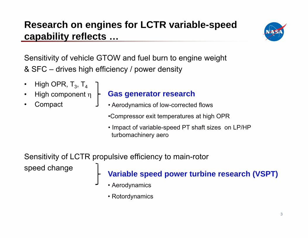
Research on engines for LCTR variable-speed capability reflects …
Sensitivity of vehicle GTOW and fuel burn to engine weight & SFC – drives high efficiency / power density
• High OPR, T3, T4
• High component • Compact
Gas generator researchAerodynamics of low corrected flows• Compact • Aerodynamics of low-corrected flows
•Compressor exit temperatures at high OPR
• Impact of variable-speed PT shaft sizes on LP/HPturbomachinery aero
Sensitivity of LCTR propulsive efficiency to main-rotor
turbomachinery aero
speed changeVariable speed power turbine research (VSPT)• Aerodynamics
R t d i
3
• Rotordynamics
Content
Gas Generator & VSPT research efforts
• Technical Challenges
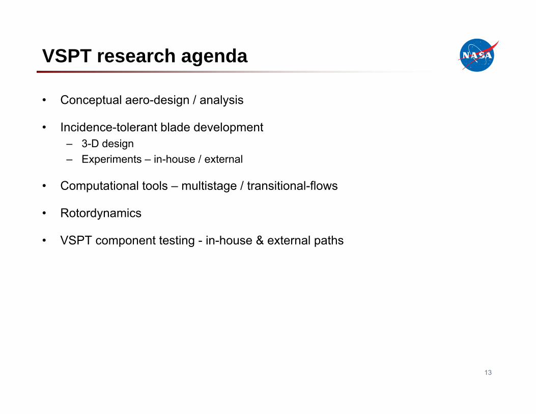
• Research agenda
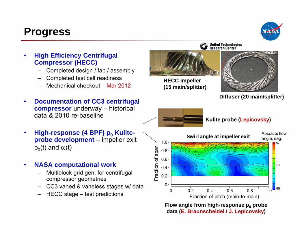
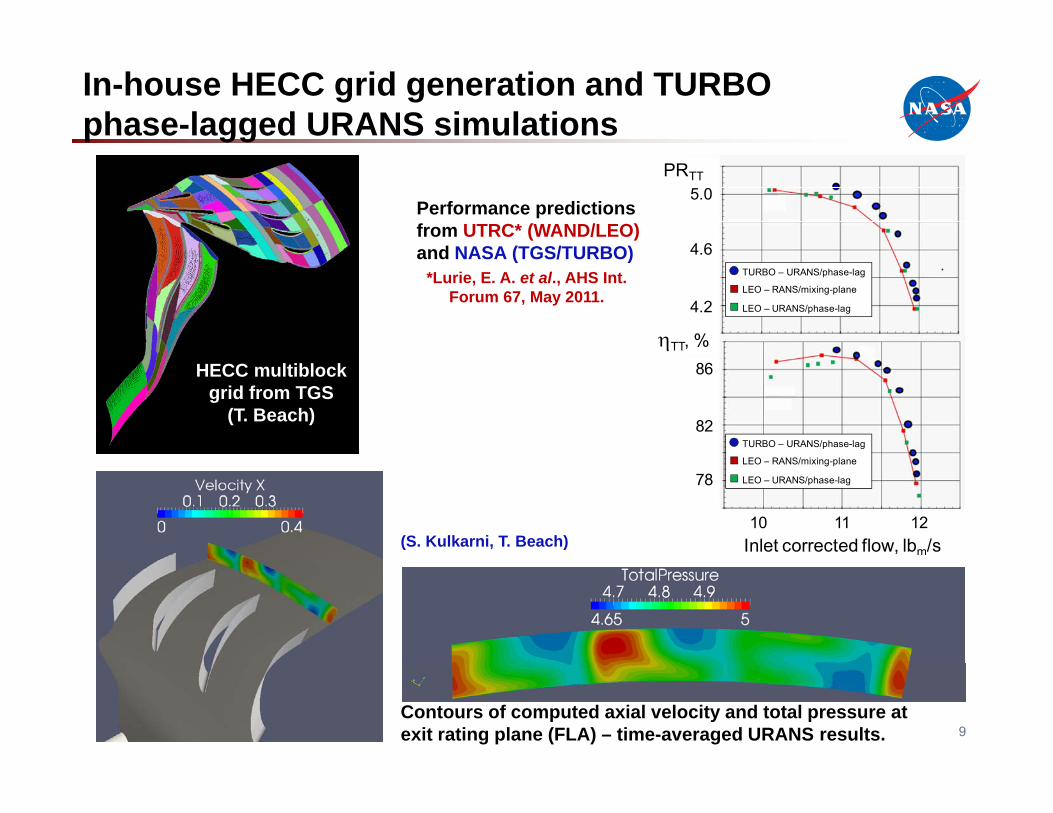
• Progress on research elements
• Next steps
4
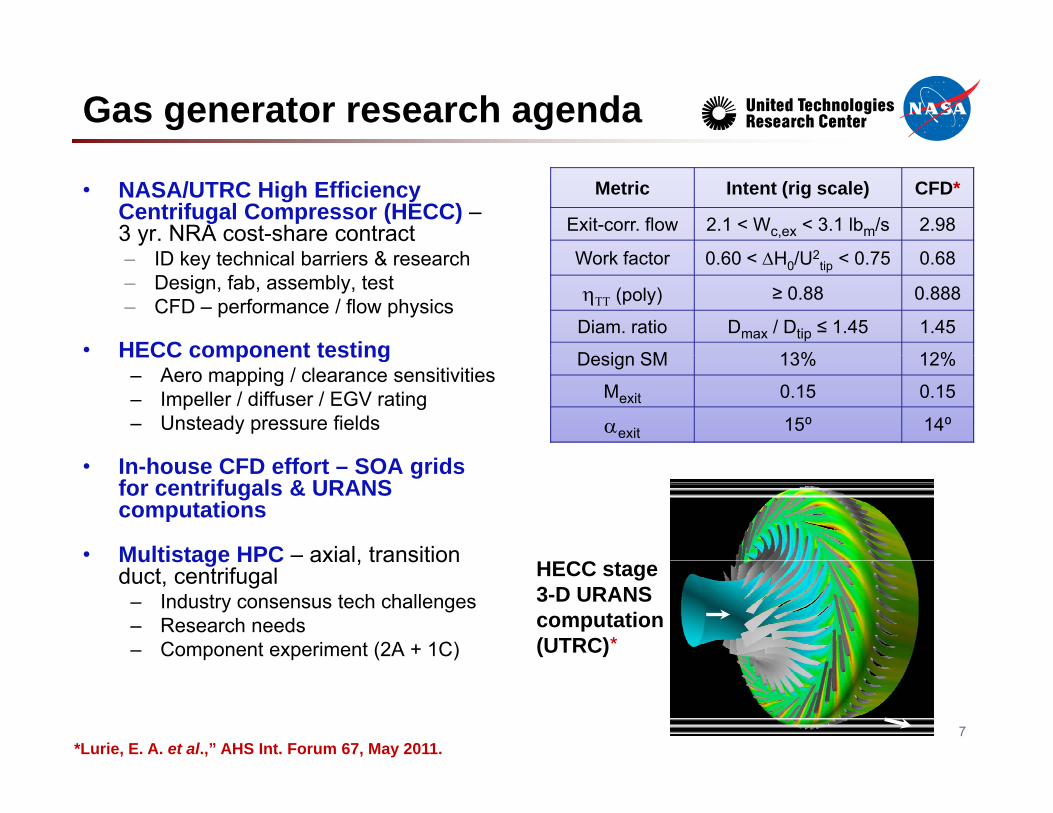
GAS GENERATOR RESEARCHGAS GENERATOR RESEARCH
5
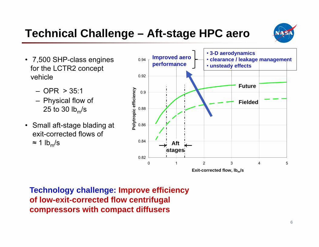
Technical Challenge – Aft-stage HPC aero
• 7,500 SHP-class engines for the LCTR2 concept vehicle 0 92
Computed contours of axial velocityand streamlines in Rotors 1 and 2 atthe 100% N* (off-design, takeoff).
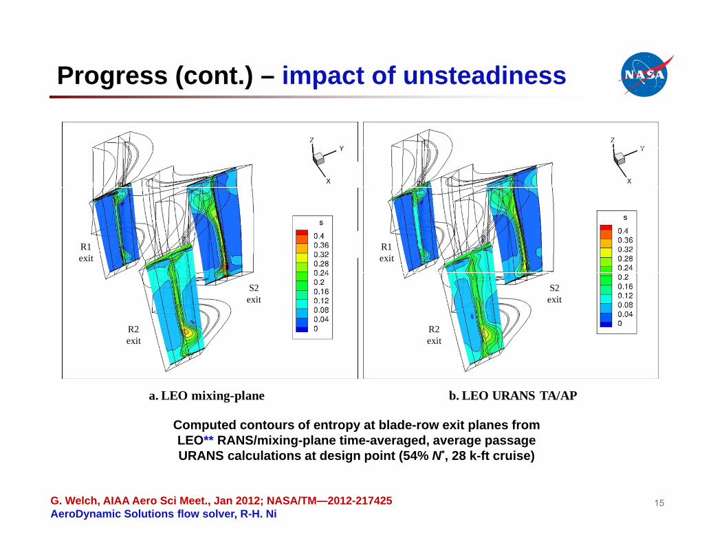
Progress (cont.) – impact of unsteadiness
R1R1 R1exit
S2exit
R1exit
S2exit
R2exit
R2exit
a. LEO mixing-plane b. LEO URANS TA/AP
Computed contours of entropy at blade-row exit planes from LEO** RANS/mixing-plane time-averaged, average passage URANS calculations at design point (54% N* 28 k-ft cruise)
15
URANS calculations at design point (54% N , 28 k-ft cruise)
G. Welch, AIAA Aero Sci Meet., Jan 2012; NASA/TM—2012-217425AeroDynamic Solutions flow solver, R-H. Ni
Linear cascade experiments – in-house
• Modified NASA GRC transonic linear cascade for VSPT negative incidence levels
Tunnel operating map*A. McVetta, P. Giel – AIAA JPC 2012 paper
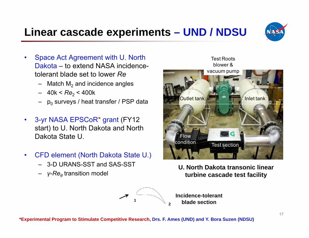
Linear cascade experiments – UND / NDSU
• Space Act Agreement with U. North Dakota – to extend NASA incidence-tolerant blade set to lower Re
Test Roots blower &
vacuum pumptolerant blade set to lower Re– Match M2 and incidence angles– 40k < Re2 < 400k– p0 surveys / heat transfer / PSP data Inlet tankOutlet tankp0 y
• 3-yr NASA EPSCoR* grant (FY12 start) to U. North Dakota and North D k t St t UDakota State U.
• CFD element (North Dakota State U.)3 D URANS SST and SAS SST
Flow condition Test section
– 3-D URANS-SST and SAS-SST – γ-Reθ transition model
U. North Dakota transonic linear turbine cascade test facility
I id t l t
17*Experimental Program to Stimulate Competitive Research, Drs. F. Ames (UND) and Y. Bora Suzen (NDSU)
12
Incidence-tolerant blade section
Computational work – W-L turbulence model for transitional flows in LPTs
• Walters-Leylek model implemented in NASA’s GlennHT
• Assessed using NASA CW-22 data setsAssessed using NASA CW 22 data sets– Heat transfer using GE2 industrial PT blade (Giel et al., 2004)– Aerodynamics using EEE tip-section blading / generation of loss bucket data
1000
1200
1400Nu
Comparison of comp ted &
600
800
1000 computed & measured Nusselt number of GE2 blading at Re = 375k
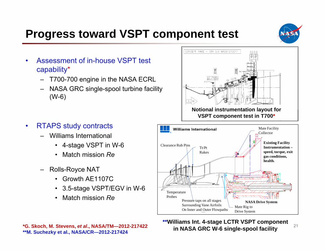
NASA Drive SystemPressure taps on all stagesSurrounding Vane Airfoils
• Growth AE1107C• 3.5-stage VSPT/EGV in W-6• Match mission Re
Surrounding Vane AirfoilsOn Inner and Outer Flowpaths
Mate Rig toDrive System
21**Williams Int. 4-stage LCTR VSPT component
in NASA GRC W-6 single-spool facility*G. Skoch, M. Stevens, et al., NASA/TM—2012-217422**M. Suchezky et al., NASA/CR—2012-217424
Next steps for VSPT
• Complete CW-22 aero testing of incidence-tolerant blading– Reports at AIAA JPC 2012 & ASME IGTI 2013
H t t f i t ith i id t l t bl d k– Heat-transfer experiments with incidence-tolerant blade pack
• Computational analysis– Report W-L / heat-transfer work at IGTI 2012– Support CW-22 experimental data synthesis– Apply TURBO with W-L model to high-speed multistage LPT
• Rotordynamics – done• Rotordynamics – done– Report at AHS Int. Forum 68
• U.S. Army Aviation Applied Technology Directorate (AATD) partnership efforts– 6.3 FATE engine program, NASA-$ VSPT option (FY12 start)– 6.2 VSPT component test, NASA-$ award (FY12 award & start)