40
1 U.S. Particle Accelerator School Fundamentals of Detector Physics and Measurements Lab - III Carl Bromberg Michigan State University Dan Green Fermilab June 18-22, 2012

1
U.S. Particle Accelerator School
Fundamentals of Detector Physics
and Measurements Lab - III
Carl Bromberg
Michigan State University
Dan Green
Fermilab
June 18-22, 2012

Outline
Lecture I
Constants, atoms, cross sections
Photoelectric, TOF
PMT, SiPM Scint, Cerenkov
Lecture II
Collisions, cross sections
Multiple scattering, radiation length
dE/dx, MIP, Range
Critical Energy
2

Outline II
Lecture III
B fields, trajectories
Quadrupoles, focal length
Drift and Diffusion
Pulse formation in unity gain and gas gain
Lecture IV
Radiation NR, Thompson, Compton
Relativistic radiation
Bremm, Pair Production
3

LHC Accelerator - Dipoles
•The LHC at 1.9 K is colder than the CMB at 2.3 K.
•The LHC is the highest energy collider in the world
•The LHC has the worlds largest cryogenic plant.
•The LHC is designed to have the highest reaction rate of any collider, design value is 1 GHz.
•The associated experiments are the largest and most complex scientific instruments ever built - a 20 year effort.
wrt Tevatron (at design)
Energy x 7
luminosity x 20
Large increase -> discovery

LHC by the Numbers - Beams
• 2808 r.f. bunches per beam, spaced by 25 nsec = 7.5 m
• Bunch intensity ~ 1.2 x 10¹¹ p per bunch
• Each bunch ~ 5 cm long, ~ 16 microns wide
• Each beam carries 362 MJ – the 2 beams have sufficient
energy to melt ~ 1 ton of cryogenic (2 K) copper.
• Quench detection, abort and collimation. Beam dump
systems are critical for safe operation.
• “Store” beams for ~ 10 hours. Protons travel ~ 10 billion
km around the LHC ring ~ 65 AU ~ round trip to Pluto ->
need a good vacuum, better than the vacuum found on the
Moon – 10-10 Torr ~ 3 million molecules/cm3. Compare to
No.
5

Solenoid Magent
6
4 /B nI cConductors of size 2 cm in z all stacked
by 4 in r for a total of n= 200 turns/m.
Then to achieve a field of 5 T, 20.8 kA of
current is required – 3 GJ @ 4T (CMS)
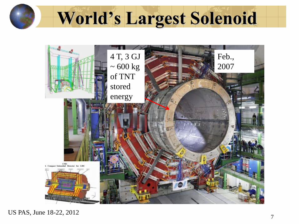
World’s Largest Solenoid
4 T, 3 GJ
~ 600 kg
of TNT
stored
energy
Feb.,
2007
7 US PAS, June 18-22, 2012
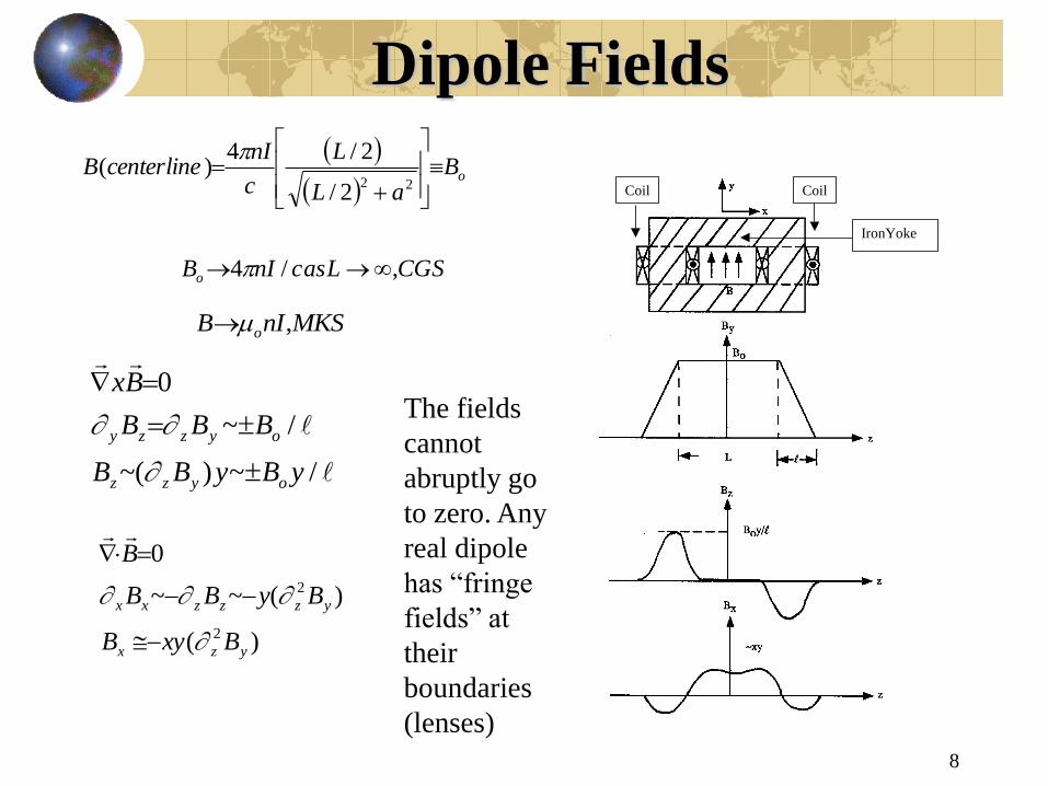
Dipole Fields
8
CGSLascnIB
BaL
L
c
nIcenterlineB
o
o
,/4
2/
2/4)(
22
MKSnIB o ,
CoilCoil
IronYoke
/~)(~
/~
0
yByBB
BBB
Bx
oyzz
oyzzy
)(
)(~~
0
2
2
yzx
yzzzxx
BxyB
ByBB
B
The fields
cannot
abruptly go
to zero. Any
real dipole
has “fringe
fields” at
their
boundaries
(lenses)
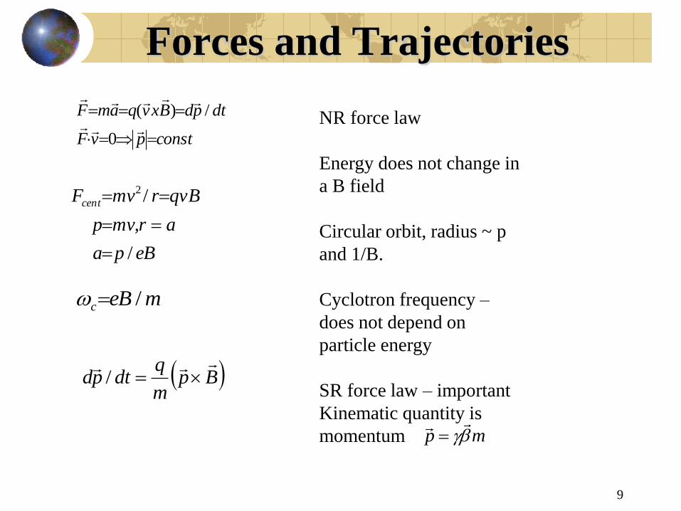
Forces and Trajectories
9
constpvF
dtpdBxvqamF
0
/)(
eBpa
armvp
qvBrmvFcent
/
,
/2
Bpm
qdtpd
/
meBc /
NR force law
Energy does not change in
a B field
Circular orbit, radius ~ p
and 1/B.
Cyclotron frequency –
does not depend on
particle energy
SR force law – important
Kinematic quantity is
momentum
p m
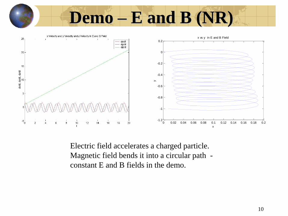
Demo – E and B (NR)
10
0 0.02 0.04 0.06 0.08 0.1 0.12 0.14 0.16 0.18 0.2-1.2
-1
-0.8
-0.6
-0.4
-0.2
0
0.2x vs y in E and B Field
x
y
Electric field accelerates a charged particle.
Magnetic field bends it into a circular path -
constant E and B fields in the demo.

Momentum Resolution
11
peLBaLB //~
( ) /
( ) 0.03
B T B
T B
p p
GeVp eLB BL
kGm
( ) /2
ST MS o
Ep L X
2/
)(
)/(~
)()/1(
)/(/1
pdp
p
Ldx
p
dpd
pp
BT
T
BT
B
BTB
BTMST pppdp )/()(~/
Suppose tracking detectors measure
the helical trajectory with accuracy
dx over a region of field B of length
L. Over that path the B field imparts
a transverse momentum impulse,
causing the momentum tranverse to
the field to rotate by a “bend angle”.
The measured angular error leads to
a fractional momentum error which
goes as ~ p.
At low momentum, since no
detector is massless, multiple
scattering limits the measurement
error of the bend angle, leading to a
~ constant fractional momentum
error.

Sagitta and Track Momentum
12
The sagitta s is:
2
2 2
(1 cos( / 2)) ~ / 8
/
~ / 8 0.3 ( ) ( ) / 8 T
s a a
L a
s L a B T L m P
e.g. L = 1m, B = 5T, Impulse = 1.5 GeV, PT = 1000 GeV -> s =
0.3 mm = 300 um. Si strip width d ~ 400 um , dx ~ 115 um. dx/L
~ 0.000115, so dp/p ~ 7.7 % for p = 1 TeV.
Note that for a uniform distribution, binary readout:
, with charge sharing across
strips one can do better
/2
2 2 2
/2
/ /12
d
d
x dx d d
US PAS, June 18-22, 2012
a
Figure of merit is
BL^2. A large B
field is desired but a
large field volume is
most important.
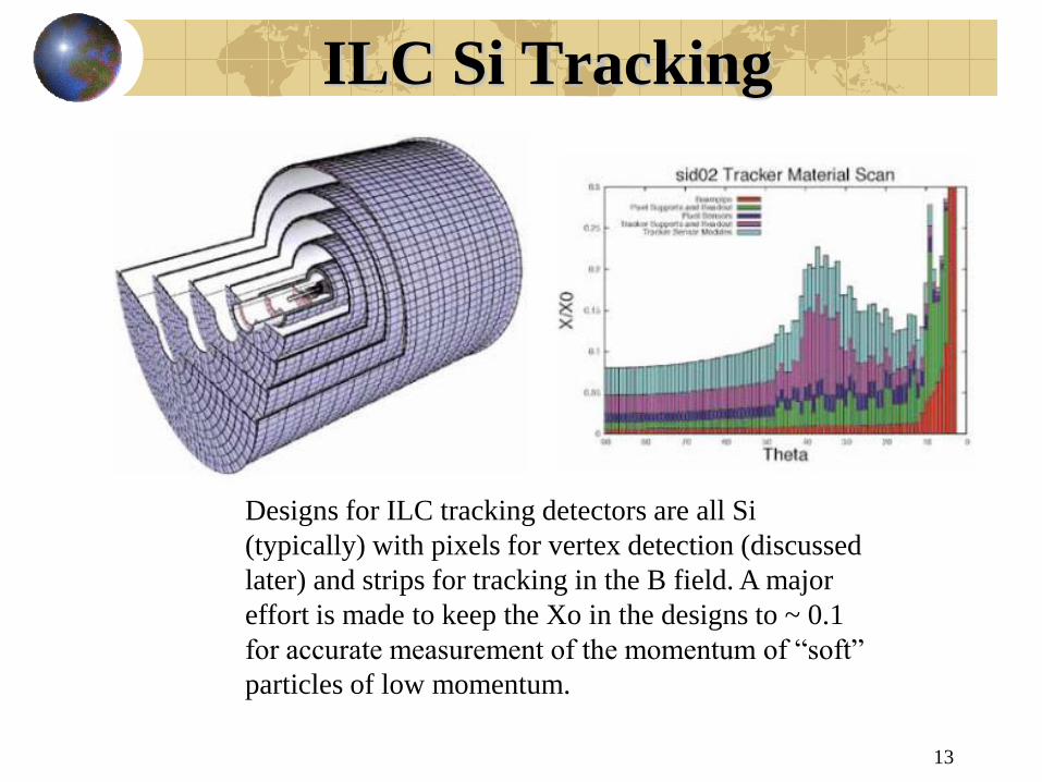
ILC Si Tracking
13
Designs for ILC tracking detectors are all Si
(typically) with pixels for vertex detection (discussed
later) and strips for tracking in the B field. A major
effort is made to keep the Xo in the designs to ~ 0.1
for accurate measurement of the momentum of “soft”
particles of low momentum.
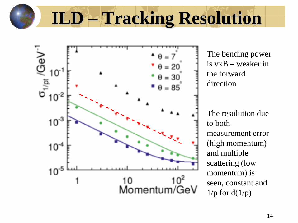
ILD – Tracking Resolution
14
The bending power
is vxB – weaker in
the forward
direction
The resolution due
to both
measurement error
(high momentum)
and multiple
scattering (low
momentum) is
seen, constant and
1/p for d(1/p)

P Resolution vs. P - CMS
15
( ) 0.3T BP erB rB
2 2(1/ ) / ( ) / ( ) ~ /T T T B T Bd P dP P d P ds er B
/ ~ ( ) / ( )
( ) / 2
T T T MS T B
T MS s i o
dP P P P
P E L X
( ) 2( ) / 2T B T loopP P erB
“loopers” <
0.75 GeV
T, m units
FOM ~ r2B
1.5 mrad at 1 TeV, 7.7 %
0.1 Xo, 6.4 MeV - MS, res =
0.0042 MS. Crossover at 54
GeV, 0.6 % total

Exact Solutions
16
)(/ Bxpqdspdp
vdtds
constant Zozo zzatsszz ,0,
yo
xo
BB
BB
y
x
cossin
sincos
2222
22
)(
)()(
)()/()(
)()/()(
Tyx
xooyoo
xoxo
yoyo
aa
ayyaxx
pppayy
pppaxx
The exact path is helical.
Circular in a plane
perpendicular to the B field
direction and a straight line
in direction of the B field
(constant direction cosign).
s = path length
The (x,y) plane has a
rotation matrix for the 2
direction cosigns with angle
= the bend angle.
The radius of curvature
refers to the momentum
transverse to the B direction.
Can use for numerical, stepping,
results for any B field.

Approximate Solutions
17
oTT
T
Bqpa
pp
/
sin
Bo
To
To
To
xoyoo
ar
ar
ar
pp
,sin/cos
cos)/(sintan
)2/()sin(
/tan
,
''
0
~ / 2
~ / ~
o
T
T B
r a
r a
At high momentum the
bend angles are small
and simple
approximations are
useful

Quadrupoles
18
yBB
xBB
BBB
B
x
y
x
y
y
x
0
22222 //
//
dsxdpvdsxdvm
BvqdsvdmvdtpdF
2
2
2
2
/
d xkx
ds
d yky
ds
k qB p
For accelerators and beamlines
besides bending and steering the
particles they need to be focused in
order to transport them a long
distance
ds=vdt, v is constant
Simple harmonic
motion. Spring
constant goes as
~B gradient and ~
1/p. Dimension of
[k] = 1/L^2

Demo – Thin/Thick Lense
19
In optics there are changes in focal length as
the lens becomes thicker. There is a similar
behavior in a magnetic lens. Obviously there
is also a “chromatic aberration” because the
lens strength ~ 1/p.

Quad Doublet
20
1/ f kL
cos sin /,
sin cos
Q oQ
oQ Q
o
Q
o
Q
xx k
xx k
xM
x
k L
Quad focal length
Thin
lens
approx
“point to
parallel”

Demo – Quad Doublet
21
Full thick lens
quadrupole matrices.
There are 3 options;
point to parallel,
parallel to point and
point to point.

Mobility in Gases
22
1
2
/
~
/~
3
o
o
od
e T o e
L N A
a
A NeE eEAv
m v N kT m
)(7601
)/(,~/
STPTorrATMP
PPEvconstE
v
o
od
d
2
2
2
~ ( / ) ,
1.7 ( / sec)
1.1( / sec)
o T
Ar
CO
Ae M
N v
cm V
cm V
Consider the motion of
ionization e in collision with
molecules in a gas. They
have a thermal velocity
which is random and are
accelerated between
collisions by an electric
field.
Drift velocity is the
acceleration times the mean
time between collisions. ~
L/vt.
Mobility is the drift velocity
per E field per STP density. e.g. E=1 kV/cm, CO2, vd= 11 m/sec

Drift and Mean Free Path
23
2 3/ 2 ~
2
3~
T T
T
T Mv kT
kTv
M
/
~
~
d
T
a eE M
v a
LeE
M v
Thermal energy
and velocity
Drift velocity
Example of collision cross
section of e on a gas – in
units of A^2.
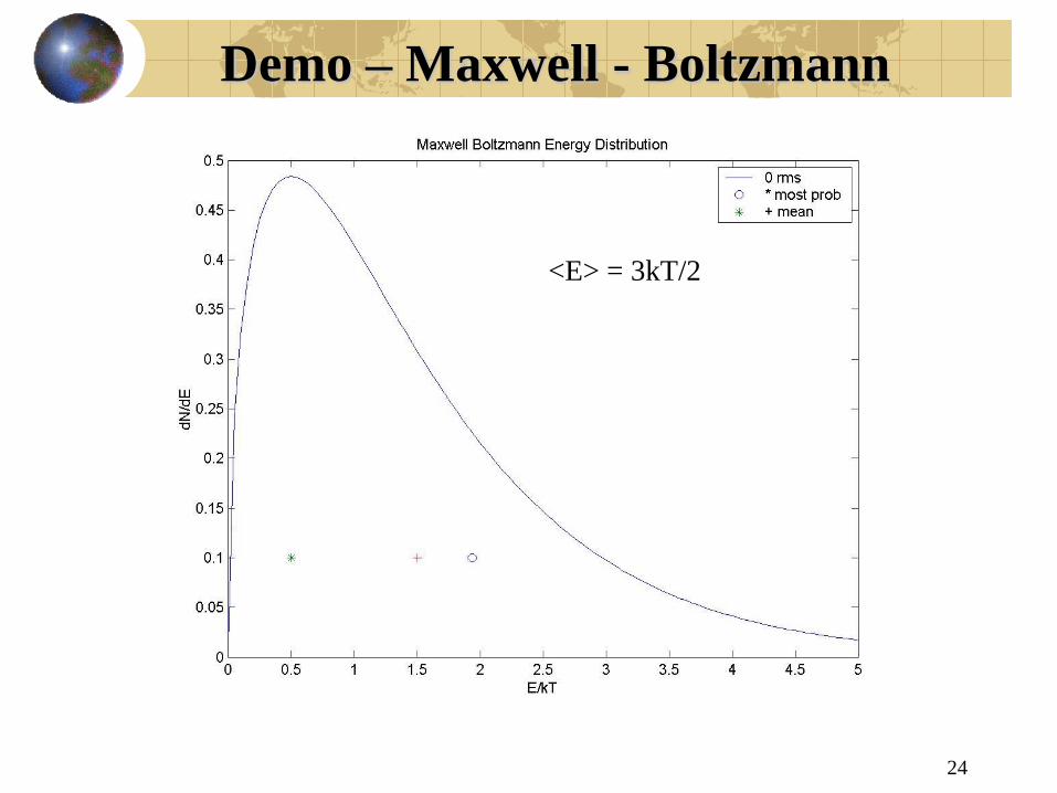
Demo – Maxwell - Boltzmann
24
<E> = 3kT/2
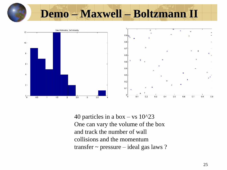
Demo – Maxwell – Boltzmann II
25
40 particles in a box – vs 10^23
One can vary the volume of the box
and track the number of wall
collisions and the momentum
transfer ~ pressure – ideal gas laws ?

LAr Drift Velocity
26
The same
analysis applies
to liquids.
Expect that drift
velocity goes as
~ E and
1/sqrt(T).
However, cross
section also
depends on the
collision energy.
Scale of velocity
is ~ mm/usec
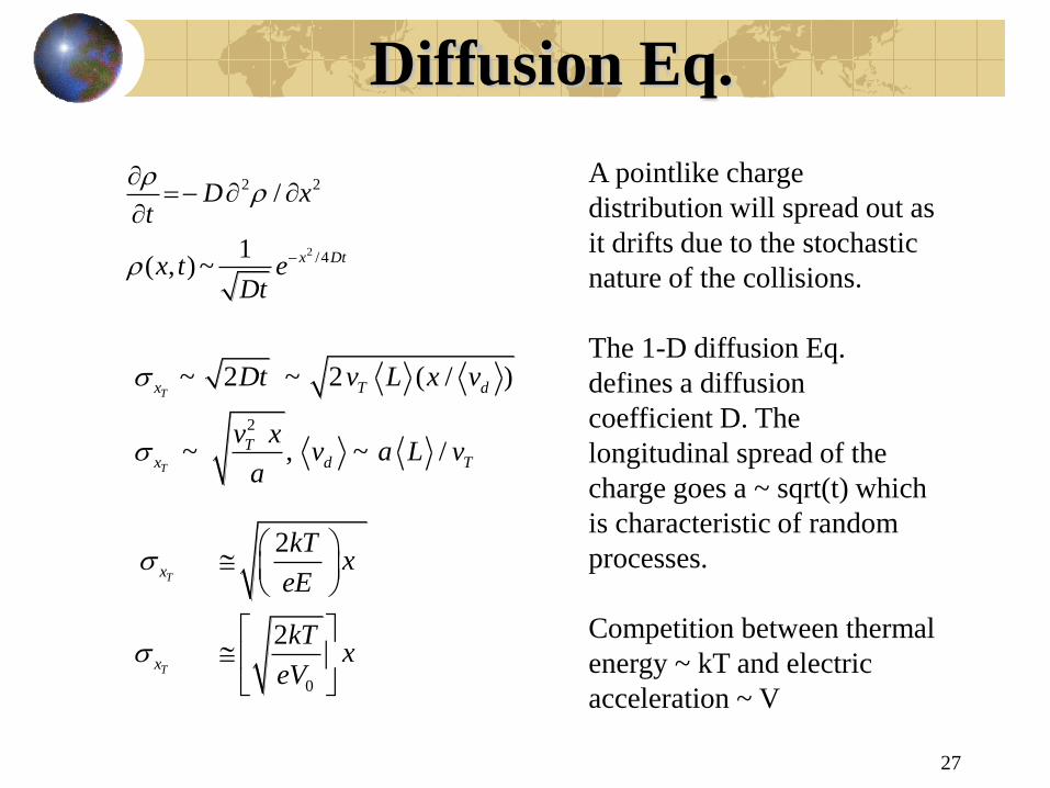
Diffusion Eq.
27
2
2 2
/4
/
1( , ) ~ x Dt
D xt
x t eDt
2
~ 2 ~ 2 ( / )
~ , ~ /
T
T
x T d
Tx d T
Dt v L x v
v xv a L v
a
0
2
2
T
T
x
x
kTx
eE
kTx
eV
A pointlike charge
distribution will spread out as
it drifts due to the stochastic
nature of the collisions.
The 1-D diffusion Eq.
defines a diffusion
coefficient D. The
longitudinal spread of the
charge goes a ~ sqrt(t) which
is characteristic of random
processes.
Competition between thermal
energy ~ kT and electric
acceleration ~ V
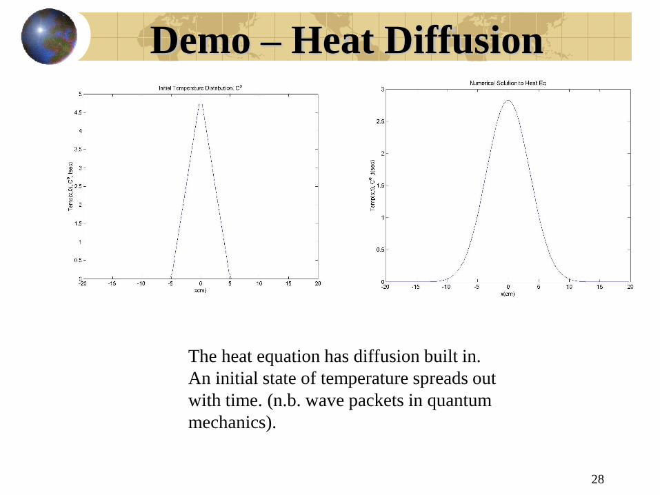
Demo – Heat Diffusion
28
The heat equation has diffusion built in.
An initial state of temperature spreads out
with time. (n.b. wave packets in quantum
mechanics).
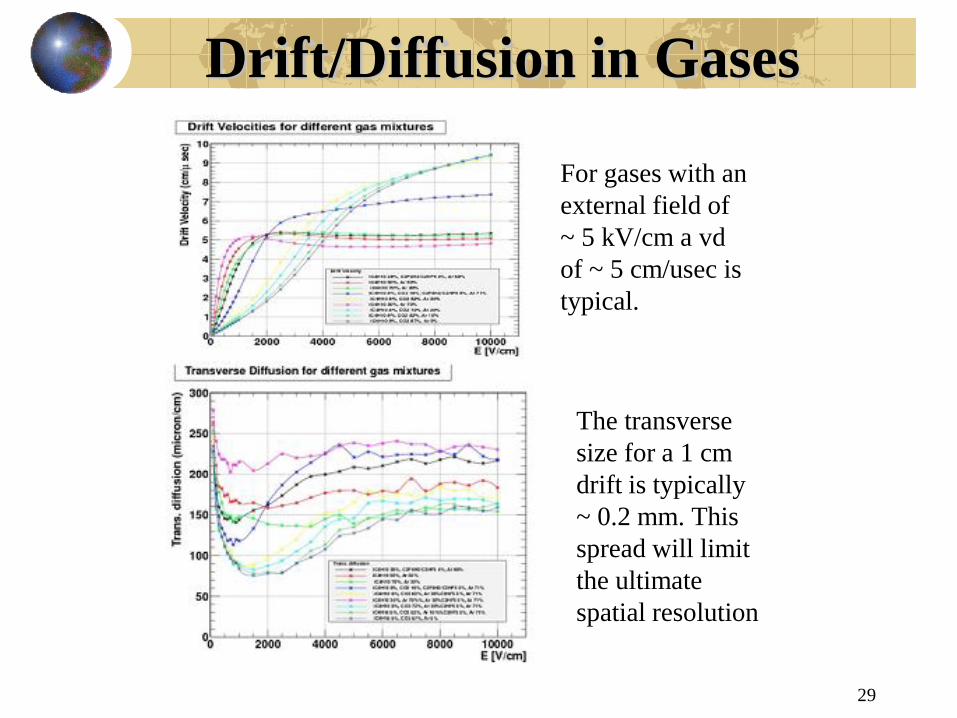
Drift/Diffusion in Gases
29
For gases with an
external field of
~ 5 kV/cm a vd
of ~ 5 cm/usec is
typical.
The transverse
size for a 1 cm
drift is typically
~ 0.2 mm. This
spread will limit
the ultimate
spatial resolution

Pulse Formation - I
30
( ) /
[ ( ) ][ ]
o
d
dU Q dQ t C Fdx
q t E v dt
Look at ionization in “unity
gain” devices.
Devices have energy U
stored in an applied E field.
Ionization charge causes a
change in energy, dU as it
moves in E to the collecting
electrode.
Source charge qs
is produced at a
point and drifts to
electrodes a
distance xo in time
td’. Current is constant. qs is
ionization charge, Q(t) is ~ t and
is the electrode charge
( )( )
( ) , 0, , /
d
o
s d d d o d
q t EdQ v dt
V
q t q for t t x v
'
'
( ) , 0,
( ) /
/
sd d
d
s d
s o
qI t t t
Q t q t
q x d

Pulse Formation - II
31
Line ionization. In
this case the
ionization is a line
from electrode to
electrode – a “gap”
of length d.
q(t) is charge
remaining in the
“gap” – decreases
linearly as charge is
swept up by the
field. I9t) is
electrode current,
decreasing linearly.
( ) 1 ,
0 ,
/
s d
d
d
d d
tq t q t
t
d v
ds
dds
tyyyq
tQdttI
tqtI
/,]2/[
)()(
)/1()/()(
2
2
2
( ) ( ) [ / ] ( ) /
( )( ) ( ) /
d o o
o
dQ t q t v dt E V q t E V dt
dQ tI t q t E V
dt

Lorentz Angle
32
/ , ( ) /
0 ( )
FF p F q E B mc ma
qa when v E B
m
2
2
/ ˆ ˆ ˆ[ ( ) ( ) ( ) ][1 ( ) ]
/
d c c
c
c
e mv E B E B E B
eB m
tan L c
E B
For ionization drifting in combined E and B
fields the path is more complicated. Take tau
as the mean time between collisions where
the ionization responds to E and B and use
that to represent the force for diffusion. The
new variable is the cyclotron frequency
which describes the NR circular motion in
the B field. Note that in strong B fields the
diffusion of the ionization can be greatly
reduced – TPC.
Angle in E,B
plane between
E and vd,
caused by B

B and Reduced Diffusion
33
2
2
ˆ[ ]
[1 ]
/ 1
d c d
d
c
d d c
v B vv
v v
TPC – drift long distances with much reduced diffusion of the
charge. The drift time is longer, but the diffusion of charge is
reduced to that the position resolution of the ionization is
improved.

TPC Construction
34
ILD proposal for
ILC detector. The
time to collect the
charge is not a
severe constraint at
the ILC
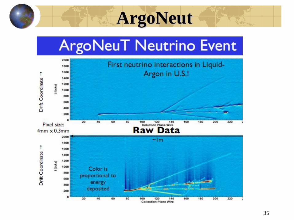
ArgoNeut
35

Pulse Formation in PWC
36
2 /
2 ln ( / ) , ( ) ln ( / ) / ln( / )
( / )( ) , / (2 / )
[ln ( / )]
o o
od
E r
V b a V r V r a b a
V rE r v dr dt r
b a
( ) ( )
( )
~ 26
r
o
A
dN r N r dr
N r N e
I eV
( )
, ( )
ln ( ) ln ( / ),
ln ( / ) ln ( / )
s
o
Na b
a Na
s s
qdV E r dr
CV
V dV V dV
q qN b NaV V V
C b a C b a
2
2
2
1 4 /
1 / , / 4
r t
a o
o o
rdr dt
r a t a
a t a
E near sense
wire
E multiply by impact in high E near the wire
~ point ionization. N(r) is the “gas gain” –
typical ionization potential in the gas.
Motion of e to the wire and positive ions to the wall. Ion motion makes for
the detected signal. Ions with mobility u move in E field defined by lambda.

PWC/Drift Electrostatics
37
Not a unity gain
device like LAr. Gas
multiplication near
the wire in the high
field region of the
PWC. The pulse has a
short rise time and a
long tail. The
characteristic time is
set by drifting a
distance ~ a in a field
E(a) ; In a drift chamber there are both
sense wires and field shaping wires to
provide a ~ uniform E field => a
constant drift velocity so that a time
of arrival of the ionization => the
distance from the wire.
2
/ ~ / ( ( ))
~ / ( ) / 2
d o
o
v E a E a
a E a a

Pulse Formation – II
38
2
2
( ) /
2 /
ln /
s o
s
I t q E V
q r
b a
22 /( )
ln / 1 /
/ 2( ) / 1 / (0) / 1 /
ln /
s
o
s o
o o
q aI t
b a t
qI t t I t
b a
2
( ) 160 /
~ 1.5 / ( sec)
8.3 sec
A
o
E a kV cm
cm V
n
Time structure of the
PWC pulse. There is a
rapid rise followed by an
inverse t falloff with a
characteristic time
constant.
A typical time
constant value

Induced Charges - Pads
39
11
2
0
( )~ ( / ) (2 / )~ ( )T s
E
E r q r a r r
/2
3
/2
1 2 1,2
1
(2 / )
( ) / , / 2 tan ( )
tan ( / 2 ) 1/
2
d
p s
d
s
p s
q q a r dy dz
q d a
d aq q
The motion of the ions
capacitively induces a
charge on the other
electrode. Used to get an
additional “pad” signal
orthogonal to the wire =>
“3d readout” – e.g. TPC

Pad Charges – 3d
40
Use the electrodes
needed for field
shaping in a drift
chamber to
provide another
independent
coordinate. In this
specific case, the
distance along the
wire.
wire


