CHAPTER 2-1 Introduction to DWDM for Metropolitan Networks OL-0884-01 2 Fundamentals of DWDM Technology The emergence of DWDM is one of the most recent and important phenomena in the development of fiber optic transmission technology. In the following discussion we briefly trace the stages of fiber optic technology and the place of DWDM in that development. We then examine the functions and components of a DWDM system, including the enabling technologies, and conclude with a high-level description of the operation of a DWDM system. Evolution of Fiber Optic Transmission The reality of fiber optic transmission had been experimentally proven in the nineteenth century, but the technology began to advance rapidly in the second half of the twentieth century with the invention of the fiberscope, which found applications in industry and medicine, such as in laparoscopic surgery. After the viability of transmitting light over fiber had been established, the next step in the development of fiber optics was to find a light source that would be sufficiently powerful and narrow. The light-emitting diode (LED) and the laser diode proved capable of meeting these requirements. Lasers went through several generations in the 1960s, culminating with the semiconductor lasers that are most widely used in fiber optics today. Light has an information-carrying capacity 10,000 times greater than the highest radio frequencies. Additional advantages of fiber over copper include the ability to carry signals over long distances, low error rates, immunity to electrical interference, security, and light weight. Aware of these characteristics, researchers in the mid-1960s proposed that optical fiber might be a suitable transmission medium. There was an obstacle, however, and that was the loss of signal strength, or attenuation, seen in the glass they were working with. Finally, in 1970, Corning produced the first communication-grade fibers. With attenuation less than 20 decibels per kilometer (dB/km), this purified glass fiber exceeded the threshold for making fiber optics a viable technology. Innovation at first proceeded slowly, as private and government monopolies that ran the telephone companies were cautious. AT&T first standardized transmission at DS3 speed (45 Mbps) for multimode fibers. Soon thereafter, single-mode fibers were shown to be capable of transmission rates 10 times that of the older type, as well as spans of 32 km (20 mi). In the early 1980s, MCI, followed by Sprint, adopted single-mode fibers for its long-distance network in the U.S. Further developments in fiber optics are closely tied to the use of the specific regions on the optical spectrum where optical attenuation is low. These regions, called windows, lie between areas of high absorption. The earliest systems were developed to operate around 850 nm, the first window in silica-based optical fiber. A second window (S band), at 1310 nm, soon proved to be superior because
Transcript
C H A P T E R
2-1Introduction to DWDM for Metropolitan Networks
OL-0884-01
2Fundamentals of DWDM Technology
The emergence of DWDM is one of the most recent and important phenomena in the development offiber optic transmission technology. In the following discussion we briefly trace the stages of fiber optictechnology and the place of DWDM in that development. We then examine the functions andcomponents of a DWDM system, including the enabling technologies, and conclude with a high-leveldescription of the operation of a DWDM system.
Evolution of Fiber Optic TransmissionThe reality of fiber optic transmission had been experimentally proven in the nineteenth century, but thetechnology began to advance rapidly in the second half of the twentieth century with the invention of thefiberscope, which found applications in industry and medicine, such as in laparoscopic surgery.
After the viability of transmitting light over fiber had been established, the next step in the developmentof fiber optics was to find a light source that would be sufficiently powerful and narrow. Thelight-emitting diode (LED) and the laser diode proved capable of meeting these requirements. Laserswent through several generations in the 1960s, culminating with the semiconductor lasers that are mostwidely used in fiber optics today.
Light has an information-carrying capacity 10,000 times greater than the highest radio frequencies.Additional advantages of fiber over copper include the ability to carry signals over long distances, lowerror rates, immunity to electrical interference, security, and light weight.
Aware of these characteristics, researchers in the mid-1960s proposed that optical fiber might be asuitable transmission medium. There was an obstacle, however, and that was the loss of signal strength,or attenuation, seen in the glass they were working with. Finally, in 1970, Corning produced the firstcommunication-grade fibers. With attenuation less than 20 decibels per kilometer (dB/km), this purifiedglass fiber exceeded the threshold for making fiber optics a viable technology.
Innovation at first proceeded slowly, as private and government monopolies that ran the telephonecompanies were cautious. AT&T first standardized transmission at DS3 speed (45 Mbps) for multimodefibers. Soon thereafter, single-mode fibers were shown to be capable of transmission rates 10 times thatof the older type, as well as spans of 32 km (20 mi). In the early 1980s, MCI, followed by Sprint, adoptedsingle-mode fibers for its long-distance network in the U.S.
Further developments in fiber optics are closely tied to the use of the specific regions on the opticalspectrum where optical attenuation is low. These regions, calledwindows, lie between areas of highabsorption. The earliest systems were developed to operate around 850 nm, the first window insilica-based optical fiber. A second window (S band), at 1310 nm, soon proved to be superior because
2-2Introduction to DWDM for Metropolitan Networks
OL-0884-01
Chapter 2 Fundamentals of DWDM TechnologyEvolution of Fiber Optic Transmission
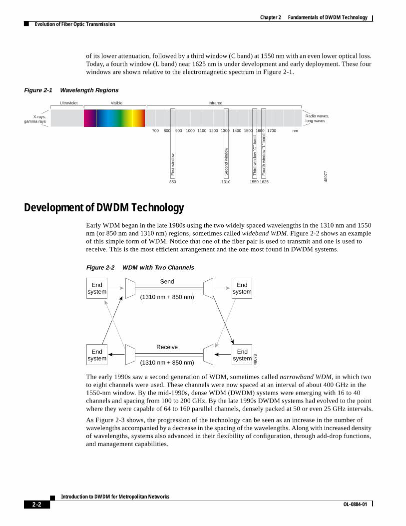
of its lower attenuation, followed by a third window (C band) at 1550 nm with an even lower optical loss.Today, a fourth window (L band) near 1625 nm is under development and early deployment. These fourwindows are shown relative to the electromagnetic spectrum in Figure 2-1.
Figure 2-1 Wavelength Regions
Development of DWDM TechnologyEarly WDM began in the late 1980s using the two widely spaced wavelengths in the 1310 nm and 1550nm (or 850 nm and 1310 nm) regions, sometimes calledwideband WDM. Figure 2-2 shows an exampleof this simple form of WDM. Notice that one of the fiber pair is used to transmit and one is used toreceive. This is the most efficient arrangement and the one most found in DWDM systems.
Figure 2-2 WDM with Two Channels
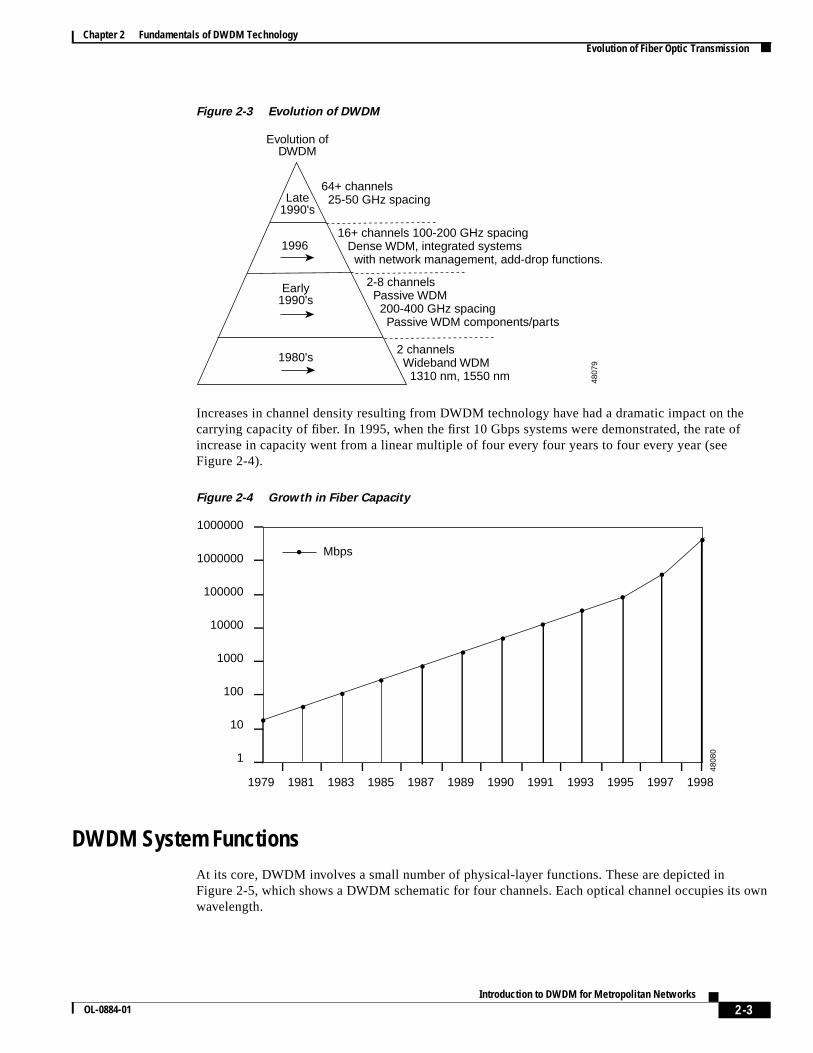
The early 1990s saw a second generation of WDM, sometimes callednarrowband WDM,in which twoto eight channels were used. These channels were now spaced at an interval of about 400 GHz in the1550-nm window. By the mid-1990s, dense WDM (DWDM) systems were emerging with 16 to 40channels and spacing from 100 to 200 GHz. By the late 1990s DWDM systems had evolved to the pointwhere they were capable of 64 to 160 parallel channels, densely packed at 50 or even 25 GHz intervals.
As Figure 2-3 shows, the progression of the technology can be seen as an increase in the number ofwavelengths accompanied by a decrease in the spacing of the wavelengths. Along with increased densityof wavelengths, systems also advanced in their flexibility of configuration, through add-drop functions,and management capabilities.
Chapter 2 Fundamentals of DWDM TechnologyEvolution of Fiber Optic Transmission
Figure 2-3 Evolution of DWDM
Increases in channel density resulting from DWDM technology have had a dramatic impact on thecarrying capacity of fiber. In 1995, when the first 10 Gbps systems were demonstrated, the rate ofincrease in capacity went from a linear multiple of four every four years to four every year (seeFigure 2-4).
Figure 2-4 Growth in Fiber Capacity
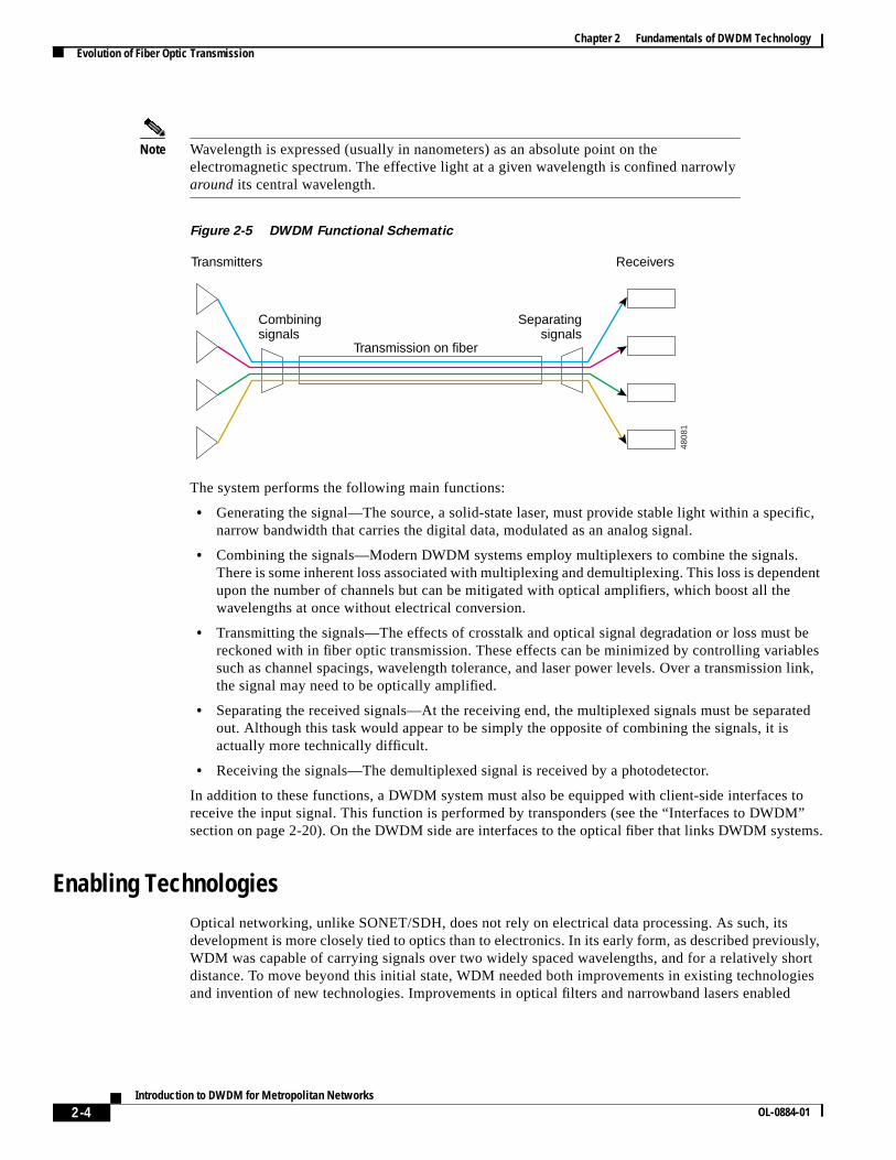
DWDM System FunctionsAt its core, DWDM involves a small number of physical-layer functions. These are depicted inFigure 2-5, which shows a DWDM schematic for four channels. Each optical channel occupies its ownwavelength.
Late1990's
Early1990's
1996
1980's
Evolution ofDWDM
64+ channels 25-50 GHz spacing
16+ channels 100-200 GHz spacing Dense WDM, integrated systems with network management, add-drop functions.
Chapter 2 Fundamentals of DWDM TechnologyEvolution of Fiber Optic Transmission
Note Wavelength is expressed (usually in nanometers) as an absolute point on theelectromagnetic spectrum. The effective light at a given wavelength is confined narrowlyaround its central wavelength.
Figure 2-5 DWDM Functional Schematic
The system performs the following main functions:
• Generating the signal—The source, a solid-state laser, must provide stable light within a specific,narrow bandwidth that carries the digital data, modulated as an analog signal.
• Combining the signals—Modern DWDM systems employ multiplexers to combine the signals.There is some inherent loss associated with multiplexing and demultiplexing. This loss is dependentupon the number of channels but can be mitigated with optical amplifiers, which boost all thewavelengths at once without electrical conversion.
• Transmitting the signals—The effects of crosstalk and optical signal degradation or loss must bereckoned with in fiber optic transmission. These effects can be minimized by controlling variablessuch as channel spacings, wavelength tolerance, and laser power levels. Over a transmission link,the signal may need to be optically amplified.
• Separating the received signals—At the receiving end, the multiplexed signals must be separatedout. Although this task would appear to be simply the opposite of combining the signals, it isactually more technically difficult.
• Receiving the signals—The demultiplexed signal is received by a photodetector.
In addition to these functions, a DWDM system must also be equipped with client-side interfaces toreceive the input signal. This function is performed by transponders (see the “Interfaces to DWDM”section on page 2-20). On the DWDM side are interfaces to the optical fiber that links DWDM systems.
Enabling TechnologiesOptical networking, unlike SONET/SDH, does not rely on electrical data processing. As such, itsdevelopment is more closely tied to optics than to electronics. In its early form, as described previously,WDM was capable of carrying signals over two widely spaced wavelengths, and for a relatively shortdistance. To move beyond this initial state, WDM needed both improvements in existing technologiesand invention of new technologies. Improvements in optical filters and narrowband lasers enabled
Transmitters Receivers
Combiningsignals
Separatingsignals
Transmission on fiber
4808
1
2-5Introduction to DWDM for Metropolitan Networks
OL-0884-01
Chapter 2 Fundamentals of DWDM TechnologyComponents and Operation
DWDM to combine more than two signal wavelengths on a fiber. The invention of the flat-gain opticalamplifier, coupled in line with the transmitting fiber to boost the optical signal, dramatically increasedthe viability of DWDM systems by greatly extending the transmission distance.
Other technologies that have been important in the development of DWDM include improved opticalfiber with lower loss and better optical transmission characteristics, EDFAs, and devices such as fiberBragg gratings used in optical add/drop multiplexers.
Components and OperationDWDM is a core technology in an optical transport network. The essential components of DWDM canbe classified by their place in the system as follows:
• On the transmit side, lasers with precise, stable wavelengths
• On the link, optical fiber that exhibits low loss and transmission performance in the relevantwavelength spectra, in addition to flat-gain optical amplifiers to boost the signal on longer spans
• On the receive side, photodetectors and optical demultiplexers using thin film filters or diffractiveelements
• Optical add/drop multiplexers and optical cross-connect components
These and other components, along with their underlying technologies, are discussed in the followingsections. While much of this information, particularly the pros and cons of various competingtechnologies, may be of more importance to a system designer than to an end user or network designer,it may also be of interest to other readers. Note as well that this is summary information and is notintended to be complete or authoritative. For in-depth information on components and underlyingtechnologies, refer to the sources cited in the “Additional Reading” section on page vii.
Optical FibersThe following discussion of DWDM components and technologies includes a refresher on optical fibers,with emphasis on their application for DWDM. Background information on subjects such as theproperties of light and optical theory can be found in many readily available printed sources and online,for example, in the tutorial at http://www.vislab.usyd.edu.au/photonics/fibres/index.html.
How Fiber WorksThe main job of optical fibers is to guide lightwaves with a minimum of attenuation (loss of signal).Optical fibers are composed of fine threads of glass in layers, called the core and cladding, that cantransmit light at about two-thirds the speed of light in a vacuum. Though admittedly anoversimplification, the transmission of light in optical fiber is commonly explained using the principleof total internal reflection. With this phenomenon, 100 percent of light that strikes a surface is reflected.By contrast, a mirror reflects about 90 percent of the light that strikes it.
Light is either reflected (it bounces back) or refracted (its angle is altered while passing through adifferent medium) depending upon the angle of incidence (the angle at which light strikes the interfacebetween an optically denser and optically thinner material).
Total internal reflection happens when the following conditions are met:
• Beams pass from a more dense to a less dense material. The difference between the optical densityof a given material and a vacuum is the material’s refractive index.
2-6Introduction to DWDM for Metropolitan Networks
OL-0884-01
Chapter 2 Fundamentals of DWDM TechnologyOptical Fibers
• The incident angle is less than the critical angle. The critical angle is the maximum angle ofincidence at which light stops being refracted and is instead totally reflected.
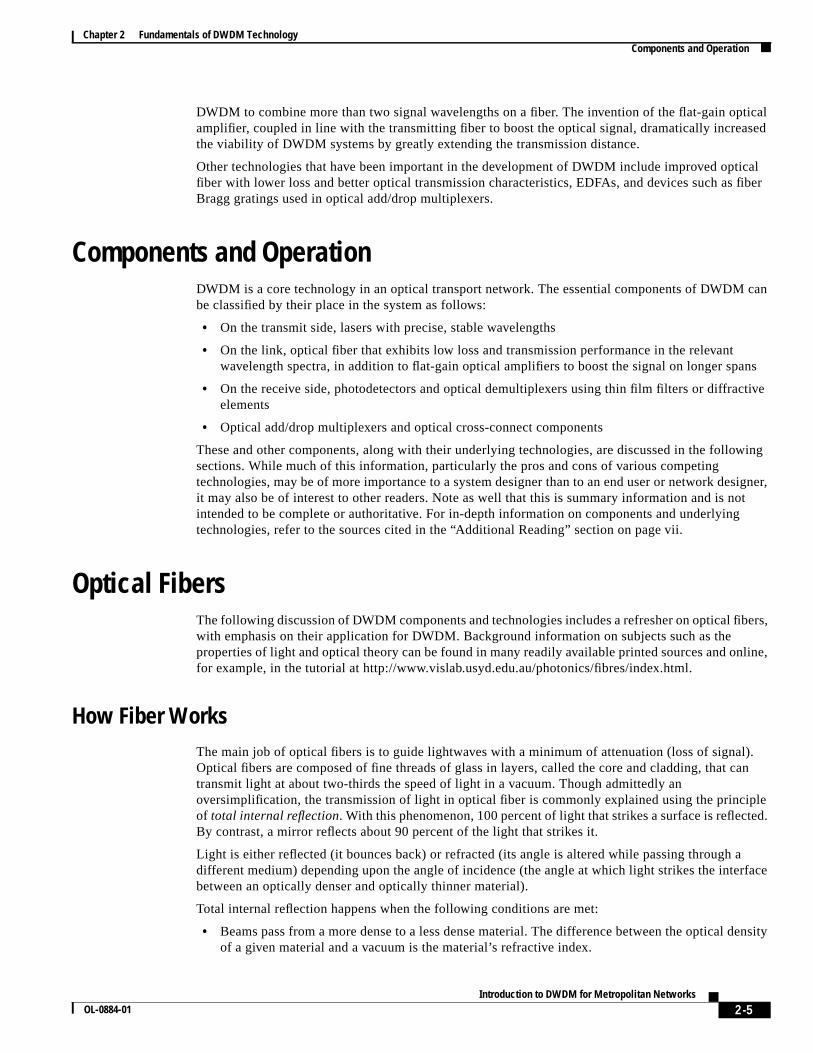
The principle of total internal reflection within a fiber core is illustrated in Figure 2-6. The core has ahigher refractive index than the cladding, allowing the beam that strikes that surface at less than thecritical angle to be reflected. The second beam does not meet the critical angle requirement and isrefracted.
Figure 2-6 Principle of Total Internal Reflection<
An optical fiber consists of two different types of highly pure, solid glass (silica)—thecore and thecladding—that are mixed with specific elements, calleddopants, to adjust their refractive indices. Thedifference between the refractive indices of the two materials causes most of the transmitted light tobounce off the cladding and stay within the core. The critical angle requirement is met by controlling theangle at which the light is injected into the fiber. Two or more layers of protective coating around thecladding ensure that the glass can be handled without damage.
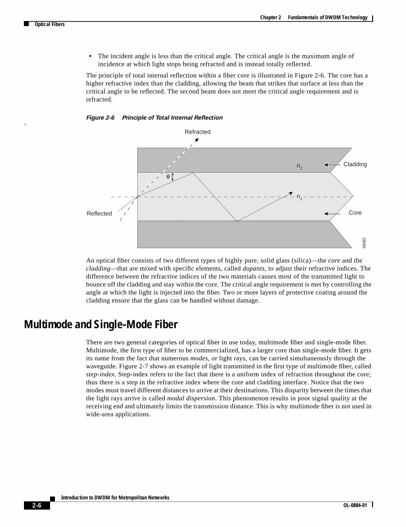
Multimode and Single-Mode FiberThere are two general categories of optical fiber in use today, multimode fiber and single-mode fiber.Multimode, the first type of fiber to be commercialized, has a larger core than single-mode fiber. It getsits name from the fact that numerousmodes, or light rays, can be carried simultaneously through thewaveguide. Figure 2-7 shows an example of light transmitted in the first type of multimode fiber, calledstep-index. Step-index refers to the fact that there is a uniform index of refraction throughout the core;thus there is a step in the refractive index where the core and cladding interface. Notice that the twomodes must travel different distances to arrive at their destinations. This disparity between the times thatthe light rays arrive is calledmodal dispersion. This phenomenon results in poor signal quality at thereceiving end and ultimately limits the transmission distance. This is why multimode fiber is not used inwide-area applications.
4808
2
Reflected
Refracted
Cladding
Core
n2
n1
θ
2-7Introduction to DWDM for Metropolitan Networks
OL-0884-01
Chapter 2 Fundamentals of DWDM TechnologyOptical Fibers
Figure 2-7 Reflected Light in Step-Index Multimode Fiber
To compensate for the dispersion drawback of step-index multimode fiber, graded-index fiber wasinvented.Graded-index refers to the fact that the refractive index of the core is graded—it graduallydecreases from the center of the core outward. The higher refraction at the center of the core slows thespeed of some light rays, allowing all the rays to reach their destination at about the same time andreducing modal dispersion.
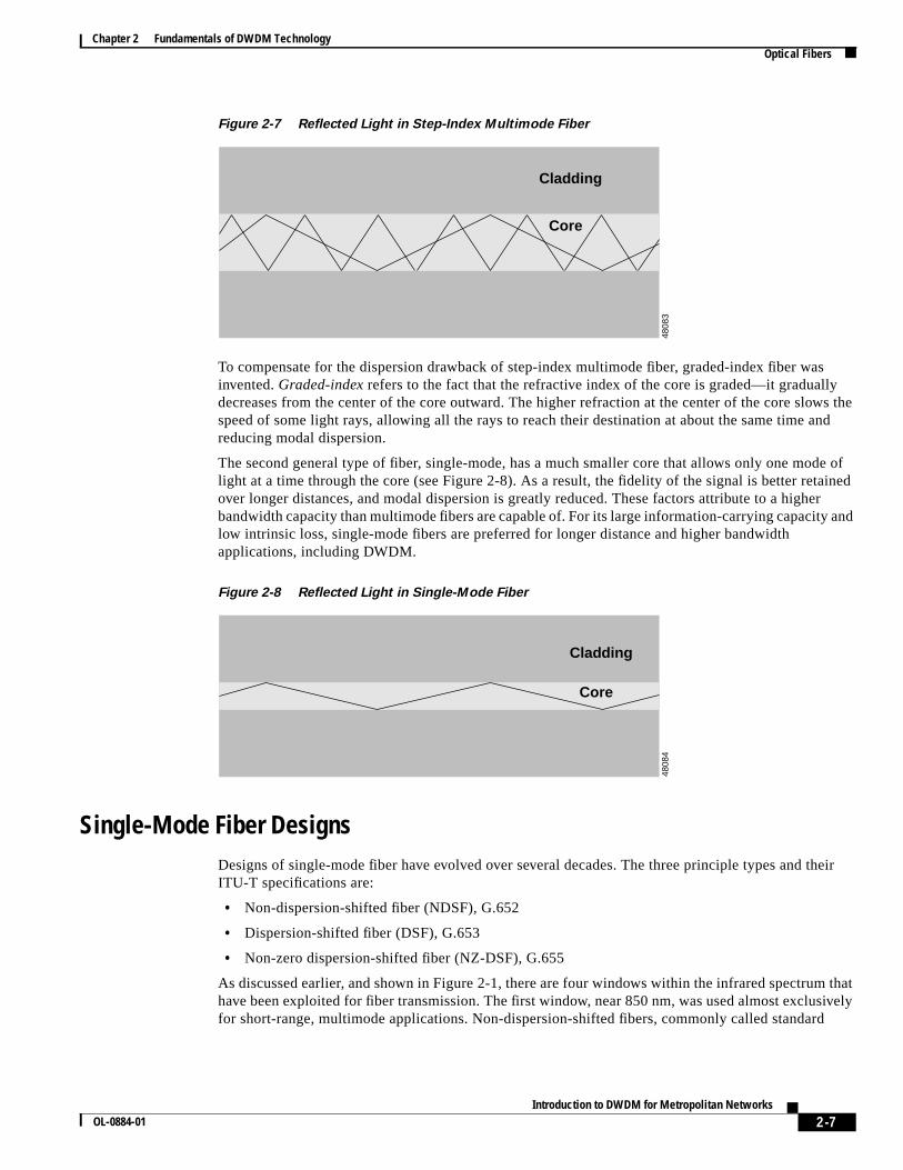
The second general type of fiber, single-mode, has a much smaller core that allows only one mode oflight at a time through the core (see Figure 2-8). As a result, the fidelity of the signal is better retainedover longer distances, and modal dispersion is greatly reduced. These factors attribute to a higherbandwidth capacity than multimode fibers are capable of. For its large information-carrying capacity andlow intrinsic loss, single-mode fibers are preferred for longer distance and higher bandwidthapplications, including DWDM.
Figure 2-8 Reflected Light in Single-Mode Fiber
Single-Mode Fiber DesignsDesigns of single-mode fiber have evolved over several decades. The three principle types and theirITU-T specifications are:
As discussed earlier, and shown in Figure 2-1, there are four windows within the infrared spectrum thathave been exploited for fiber transmission. The first window, near 850 nm, was used almost exclusivelyfor short-range, multimode applications. Non-dispersion-shifted fibers, commonly called standard
Cladding
Core
4808
3Cladding
Core
4808
4
2-8Introduction to DWDM for Metropolitan Networks
OL-0884-01
Chapter 2 Fundamentals of DWDM TechnologyOptical Fibers
single-mode (SM) fibers, were designed for use in the second window, near 1310 nm. To optimize thefiber’s performance in this window, the fiber was designed so that chromatic dispersion would be closeto zero near the 1310-nm wavelength
As optical fiber use became more common and the needs for greater bandwidth and distance increased,a third window, near 1550 nm, was exploited for single-mode transmission. The third window, or C band,offered two advantages: it had much lower attenuation, and its operating frequency was the same as thatof the new erbium-doped fiber amplifiers (EDFAs). However, its dispersion characteristics were severelylimiting. This was overcome to a certain extent by using narrower linewidth and higher power lasers. Butbecause the third window had lower attenuation than the 1310-nm window, manufacturers came up withthe dispersion-shifted fiber design, which moved the zero-dispersion point to the 1550-nm region.Although this solution now meant that the lowest optical attenuation and the zero-dispersion pointscoincided in the 1550-nm window, it turned out that there are destructive nonlinearities in optical fibernear the zero-dispersion point for which there is no effective compensation. Because of this limitation,these fibers are not suitable for DWDM applications.
The third type, non-zero dispersion-shifted fiber, is designed specifically to meet the needs of DWDMapplications. The aim of this design is to make the dispersion low in the 1550-nm region, but not zero.This strategy effectively introduces a controlled amount of dispersion, which counters nonlinear effectssuch as four-wave mixing (see the “Other Nonlinear Effects” section on page 2-11) that can hinder theperformance of DWDM systems.
Transmission Challenges
Transmission of light in optical fiber presents several challenges that must be dealt with. These fall intothe following three broad categories:
• Attenuation—decay of signal strength, or loss of light power, as the signal propagates through thefiber
• Chromatic dispersion—spreading of light pulses as they travel down the fiber
• Nonlinearities—cumulative effects from the interaction of light with the material through which ittravels, resulting in changes in the lightwave and interactions between lightwaves
Each of these effects has several causes, not all of which affect DWDM. The discussion in the followingsections addresses those causes that are relevant to DWDM.
Attenuation
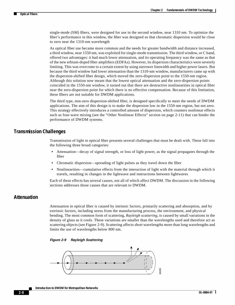
Attenuation in optical fiber is caused by intrinsic factors, primarily scattering and absorption, and byextrinsic factors, including stress from the manufacturing process, the environment, and physicalbending. The most common form of scattering,Rayleigh scattering, is caused by small variations in thedensity of glass as it cools. These variations are smaller than the wavelengths used and therefore act asscattering objects (see Figure 2-9). Scattering affects short wavelengths more than long wavelengths andlimits the use of wavelengths below 800 nm.
Figure 2-9 Rayleigh Scattering
4808
5
2-9Introduction to DWDM for Metropolitan Networks
OL-0884-01
Chapter 2 Fundamentals of DWDM TechnologyOptical Fibers
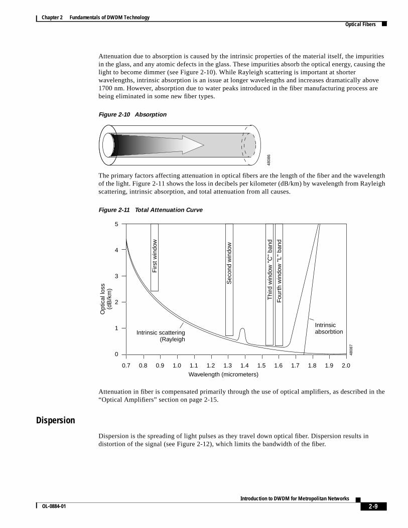
Attenuation due to absorption is caused by the intrinsic properties of the material itself, the impuritiesin the glass, and any atomic defects in the glass. These impurities absorb the optical energy, causing thelight to become dimmer (see Figure 2-10). While Rayleigh scattering is important at shorterwavelengths, intrinsic absorption is an issue at longer wavelengths and increases dramatically above1700 nm. However, absorption due to water peaks introduced in the fiber manufacturing process arebeing eliminated in some new fiber types.
Figure 2-10 Absorption
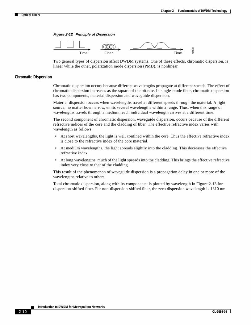
The primary factors affecting attenuation in optical fibers are the length of the fiber and the wavelengthof the light. Figure 2-11 shows the loss in decibels per kilometer (dB/km) by wavelength from Rayleighscattering, intrinsic absorption, and total attenuation from all causes.
Figure 2-11 Total Attenuation Curve
Attenuation in fiber is compensated primarily through the use of optical amplifiers, as described in the“Optical Amplifiers” section on page 2-15.
Dispersion
Dispersion is the spreading of light pulses as they travel down optical fiber. Dispersion results indistortion of the signal (see Figure 2-12), which limits the bandwidth of the fiber.
2-10Introduction to DWDM for Metropolitan Networks
OL-0884-01
Chapter 2 Fundamentals of DWDM TechnologyOptical Fibers
Figure 2-12 Principle of Dispersion
Two general types of dispersion affect DWDM systems. One of these effects, chromatic dispersion, islinear while the other, polarization mode dispersion (PMD), is nonlinear.
Chromatic Dispersion
Chromatic dispersion occurs because different wavelengths propagate at different speeds. The effect ofchromatic dispersion increases as the square of the bit rate. In single-mode fiber, chromatic dispersionhas two components, material dispersion and waveguide dispersion.
Material dispersion occurs when wavelengths travel at different speeds through the material. A lightsource, no matter how narrow, emits several wavelengths within a range. Thus, when this range ofwavelengths travels through a medium, each individual wavelength arrives at a different time.
The second component of chromatic dispersion, waveguide dispersion, occurs because of the differentrefractive indices of the core and the cladding of fiber. The effective refractive index varies withwavelength as follows:
• At short wavelengths, the light is well confined within the core. Thus the effective refractive indexis close to the refractive index of the core material.
• At medium wavelengths, the light spreads slightly into the cladding. This decreases the effectiverefractive index.
• At long wavelengths, much of the light spreads into the cladding. This brings the effective refractiveindex very close to that of the cladding.
This result of the phenomenon of waveguide dispersion is a propagation delay in one or more of thewavelengths relative to others.
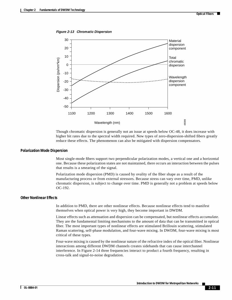
Total chromatic dispersion, along with its components, is plotted by wavelength in Figure 2-13 fordispersion-shifted fiber. For non-dispersion-shifted fiber, the zero dispersion wavelength is 1310 nm.
Time Fiber Time 4808
8
2-11Introduction to DWDM for Metropolitan Networks
OL-0884-01
Chapter 2 Fundamentals of DWDM TechnologyOptical Fibers
Figure 2-13 Chromatic Dispersion
Though chromatic dispersion is generally not an issue at speeds below OC-48, it does increase withhigher bit rates due to the spectral width required. New types of zero-dispersion-shifted fibers greatlyreduce these effects. The phenomenon can also be mitigated with dispersion compensators.
Polarization Mode Dispersion
Most single-mode fibers support two perpendicular polarization modes, a vertical one and a horizontalone. Because these polarization states are not maintained, there occurs an interaction between the pulsesthat results is a smearing of the signal.
Polarization mode dispersion (PMD) is caused by ovality of the fiber shape as a result of themanufacturing process or from external stressors. Because stress can vary over time, PMD, unlikechromatic dispersion, is subject to change over time. PMD is generally not a problem at speeds belowOC-192.
Other Nonlinear Effects
In addition to PMD, there are other nonlinear effects. Because nonlinear effects tend to manifestthemselves when optical power is very high, they become important in DWDM.
Linear effects such as attenuation and dispersion can be compensated, but nonlinear effectsaccumulate.They are the fundamental limiting mechanisms to the amount of data that can be transmitted in opticalfiber. The most important types of nonlinear effects are stimulated Brillouin scattering, stimulatedRaman scattering, self-phase modulation, and four-wave mixing. In DWDM, four-wave mixing is mostcritical of these types.
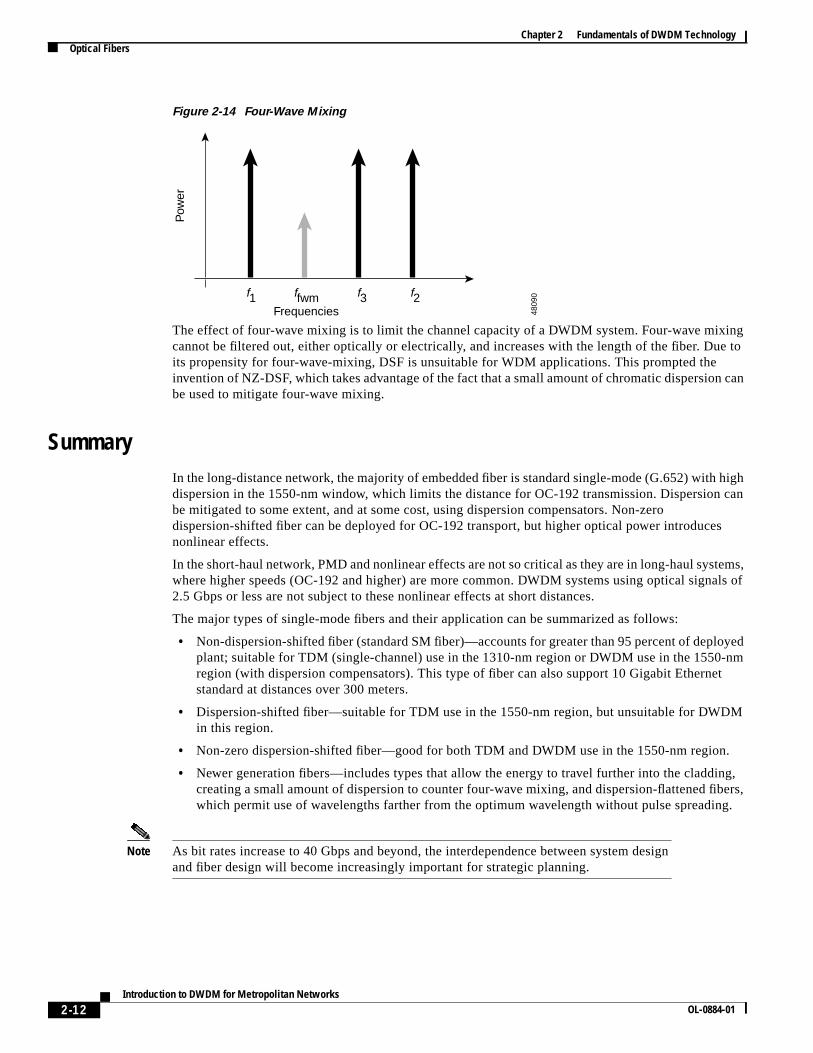
Four-wave mixing is caused by the nonlinear nature of the refractive index of the optical fiber. Nonlinearinteractions among different DWDM channels creates sidebands that can cause interchannelinterference. In Figure 2-14 three frequencies interact to product a fourth frequency, resulting incross-talk and signal-to-noise degradation.
30
20
10
0
-10
-20
-30
-40
-50
1100 1200 1300 1400 1500 1600
Wavelength (nm)
Dis
pers
ion
(ps/
nm*k
m)
Material dispersioncomponent
Totalchromaticdispersion
Wavelengthdispersioncomponent
4808
9
2-12Introduction to DWDM for Metropolitan Networks
OL-0884-01
Chapter 2 Fundamentals of DWDM TechnologyOptical Fibers
Figure 2-14 Four-Wave Mixing
The effect of four-wave mixing is to limit the channel capacity of a DWDM system. Four-wave mixingcannot be filtered out, either optically or electrically, and increases with the length of the fiber. Due toits propensity for four-wave-mixing, DSF is unsuitable for WDM applications. This prompted theinvention of NZ-DSF, which takes advantage of the fact that a small amount of chromatic dispersion canbe used to mitigate four-wave mixing.
SummaryIn the long-distance network, the majority of embedded fiber is standard single-mode (G.652) with highdispersion in the 1550-nm window, which limits the distance for OC-192 transmission. Dispersion canbe mitigated to some extent, and at some cost, using dispersion compensators. Non-zerodispersion-shifted fiber can be deployed for OC-192 transport, but higher optical power introducesnonlinear effects.
In the short-haul network, PMD and nonlinear effects are not so critical as they are in long-haul systems,where higher speeds (OC-192 and higher) are more common. DWDM systems using optical signals of2.5 Gbps or less are not subject to these nonlinear effects at short distances.
The major types of single-mode fibers and their application can be summarized as follows:
• Non-dispersion-shifted fiber (standard SM fiber)—accounts for greater than 95 percent of deployedplant; suitable for TDM (single-channel) use in the 1310-nm region or DWDM use in the 1550-nmregion (with dispersion compensators). This type of fiber can also support 10 Gigabit Ethernetstandard at distances over 300 meters.
• Dispersion-shifted fiber—suitable for TDM use in the 1550-nm region, but unsuitable for DWDMin this region.
• Non-zero dispersion-shifted fiber—good for both TDM and DWDM use in the 1550-nm region.
• Newer generation fibers—includes types that allow the energy to travel further into the cladding,creating a small amount of dispersion to counter four-wave mixing, and dispersion-flattened fibers,which permit use of wavelengths farther from the optimum wavelength without pulse spreading.
Note As bit rates increase to 40 Gbps and beyond, the interdependence between system designand fiber design will become increasingly important for strategic planning.
Pow
er
f1 f3 f2ffwmFrequencies 48
090
2-13Introduction to DWDM for Metropolitan Networks
OL-0884-01
Chapter 2 Fundamentals of DWDM TechnologyLight Sources and Detectors
Light Sources and DetectorsLight emitters and light detectors are active devices at opposite ends of an optical transmission system.Light sources, or light emitters, are transmit-side devices that convert electrical signals to light pulses.The process of this conversion, or modulation, can be accomplished by externally modulating acontinuous wave of light or by using a device that can generate modulated light directly. Light detectorsperform the opposite function of light emitters. They are receive-side opto-electronic devices thatconvert light pulses into electrical signals.
Light Emitters—LEDs and LasersThe light source used in the design of a system is an important consideration because it can be one ofthe most costly elements. Its characteristics are often a strong limiting factor in the final performance ofthe optical link. Light emitting devices used in optical transmission must be compact, monochromatic,stable, and long-lasting.
Note Monochromatic is a relative term; in practice there are only light sources within a certainrange. Stability of a light source is a measure of how constant its intensity and wavelengthare.
Two general types of light emitting devices are used in optical transmission, light-emitting diodes(LEDs) and laser diodes, or semiconductor lasers. LEDs are relatively slow devices, suitable for use atspeeds of less than 1 Gbps, they exhibit a relatively wide spectrum width, and they transmit light in arelatively wide cone. These inexpensive devices are often used in multimode fiber communications.Semiconductor lasers, on the other hand, have performance characteristics better suited to single-modefiber applications.
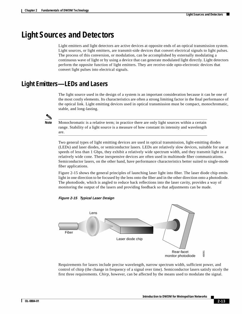
Figure 2-15 shows the general principles of launching laser light into fiber. The laser diode chip emitslight in one direction to be focused by the lens onto the fiber and in the other direction onto a photodiode.The photodiode, which is angled to reduce back reflections into the laser cavity, provides a way ofmonitoring the output of the lasers and providing feedback so that adjustments can be made.
Figure 2-15 Typical Laser Design
Requirements for lasers include precise wavelength, narrow spectrum width, sufficient power, andcontrol of chirp (the change in frequency of a signal over time). Semiconductor lasers satisfy nicely thefirst three requirements. Chirp, however, can be affected by the means used to modulate the signal.
Rear-facetmonitor photodiode
Laser diode chip
Fiber
Lens
4809
1
2-14Introduction to DWDM for Metropolitan Networks
OL-0884-01
Chapter 2 Fundamentals of DWDM TechnologyLight Sources and Detectors
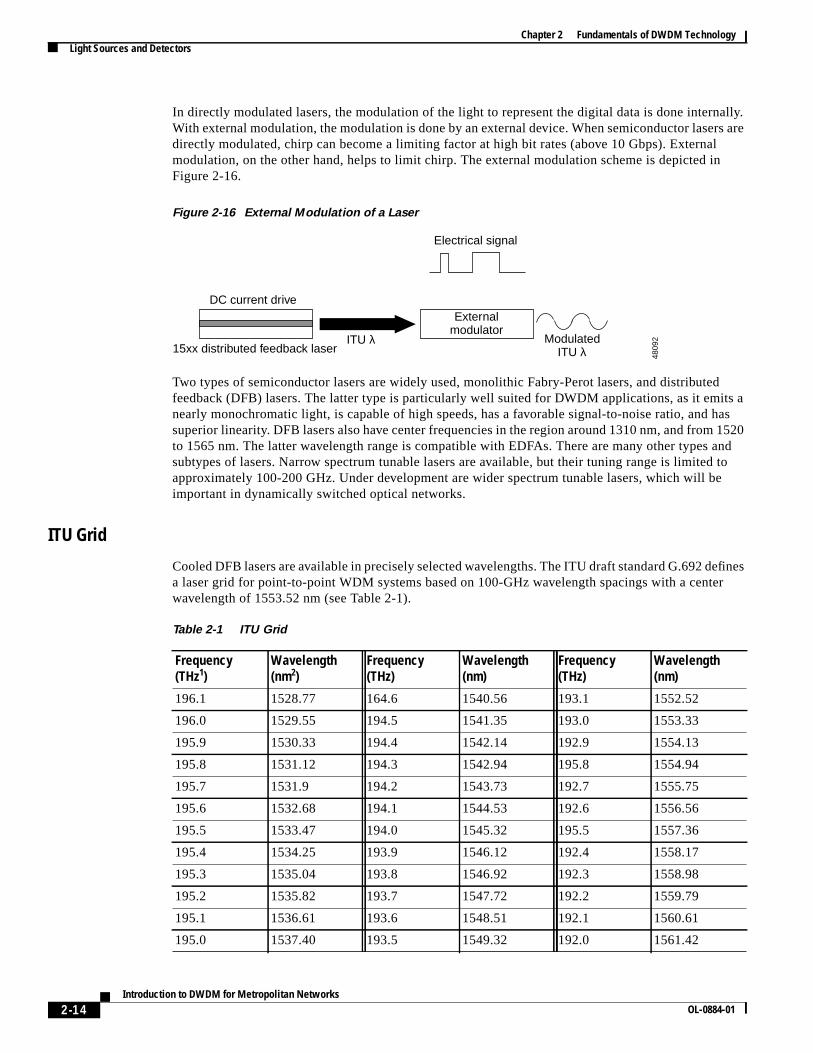
In directly modulated lasers, the modulation of the light to represent the digital data is done internally.With external modulation, the modulation is done by an external device. When semiconductor lasers aredirectly modulated, chirp can become a limiting factor at high bit rates (above 10 Gbps). Externalmodulation, on the other hand, helps to limit chirp. The external modulation scheme is depicted inFigure 2-16.
Figure 2-16 External Modulation of a Laser
Two types of semiconductor lasers are widely used, monolithic Fabry-Perot lasers, and distributedfeedback (DFB) lasers. The latter type is particularly well suited for DWDM applications, as it emits anearly monochromatic light, is capable of high speeds, has a favorable signal-to-noise ratio, and hassuperior linearity. DFB lasers also have center frequencies in the region around 1310 nm, and from 1520to 1565 nm. The latter wavelength range is compatible with EDFAs. There are many other types andsubtypes of lasers. Narrow spectrum tunable lasers are available, but their tuning range is limited toapproximately 100-200 GHz. Under development are wider spectrum tunable lasers, which will beimportant in dynamically switched optical networks.
ITU Grid
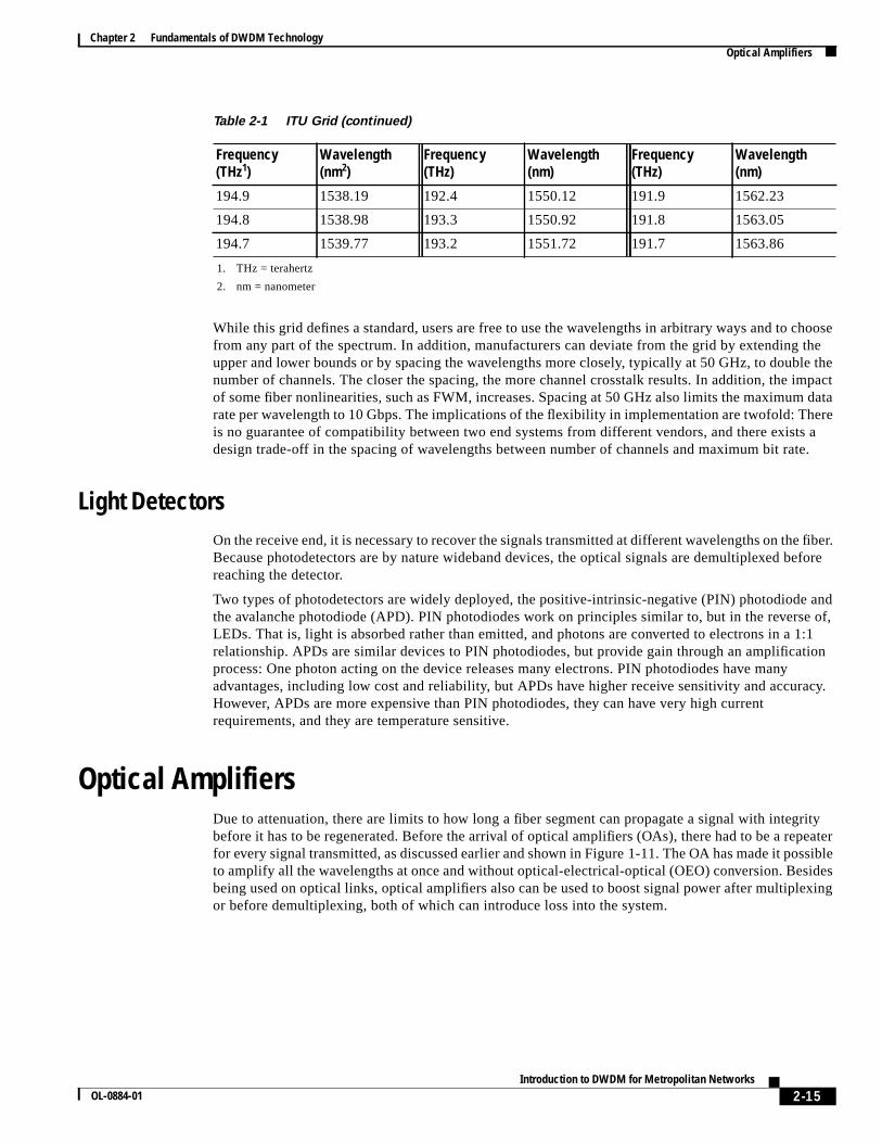
Cooled DFB lasers are available in precisely selected wavelengths. The ITU draft standard G.692 definesa laser grid for point-to-point WDM systems based on 100-GHz wavelength spacings with a centerwavelength of 1553.52 nm (see Table 2-1).
Externalmodulator
ModulatedITU λ15xx distributed feedback laser
DC current drive
ITU λ
Electrical signal
4809
2
Table 2-1 ITU Grid
Frequency(THz1)
Wavelength(nm2)
Frequency(THz)
Wavelength(nm)
Frequency(THz)
Wavelength(nm)
196.1 1528.77 164.6 1540.56 193.1 1552.52
196.0 1529.55 194.5 1541.35 193.0 1553.33
195.9 1530.33 194.4 1542.14 192.9 1554.13
195.8 1531.12 194.3 1542.94 195.8 1554.94
195.7 1531.9 194.2 1543.73 192.7 1555.75
195.6 1532.68 194.1 1544.53 192.6 1556.56
195.5 1533.47 194.0 1545.32 195.5 1557.36
195.4 1534.25 193.9 1546.12 192.4 1558.17
195.3 1535.04 193.8 1546.92 192.3 1558.98
195.2 1535.82 193.7 1547.72 192.2 1559.79
195.1 1536.61 193.6 1548.51 192.1 1560.61
195.0 1537.40 193.5 1549.32 192.0 1561.42
2-15Introduction to DWDM for Metropolitan Networks
OL-0884-01
Chapter 2 Fundamentals of DWDM TechnologyOptical Amplifiers
While this grid defines a standard, users are free to use the wavelengths in arbitrary ways and to choosefrom any part of the spectrum. In addition, manufacturers can deviate from the grid by extending theupper and lower bounds or by spacing the wavelengths more closely, typically at 50 GHz, to double thenumber of channels. The closer the spacing, the more channel crosstalk results. In addition, the impactof some fiber nonlinearities, such as FWM, increases. Spacing at 50 GHz also limits the maximum datarate per wavelength to 10 Gbps. The implications of the flexibility in implementation are twofold: Thereis no guarantee of compatibility between two end systems from different vendors, and there exists adesign trade-off in the spacing of wavelengths between number of channels and maximum bit rate.
Light DetectorsOn the receive end, it is necessary to recover the signals transmitted at different wavelengths on the fiber.Because photodetectors are by nature wideband devices, the optical signals are demultiplexed beforereaching the detector.
Two types of photodetectors are widely deployed, the positive-intrinsic-negative (PIN) photodiode andthe avalanche photodiode (APD). PIN photodiodes work on principles similar to, but in the reverse of,LEDs. That is, light is absorbed rather than emitted, and photons are converted to electrons in a 1:1relationship. APDs are similar devices to PIN photodiodes, but provide gain through an amplificationprocess: One photon acting on the device releases many electrons. PIN photodiodes have manyadvantages, including low cost and reliability, but APDs have higher receive sensitivity and accuracy.However, APDs are more expensive than PIN photodiodes, they can have very high currentrequirements, and they are temperature sensitive.
Optical AmplifiersDue to attenuation, there are limits to how long a fiber segment can propagate a signal with integritybefore it has to be regenerated. Before the arrival of optical amplifiers (OAs), there had to be a repeaterfor every signal transmitted, as discussed earlier and shown in Figure 1-11. The OA has made it possibleto amplify all the wavelengths at once and without optical-electrical-optical (OEO) conversion. Besidesbeing used on optical links, optical amplifiers also can be used to boost signal power after multiplexingor before demultiplexing, both of which can introduce loss into the system.
194.9 1538.19 192.4 1550.12 191.9 1562.23
194.8 1538.98 193.3 1550.92 191.8 1563.05
194.7 1539.77 193.2 1551.72 191.7 1563.86
1. THz = terahertz
2. nm = nanometer
Table 2-1 ITU Grid (continued)
Frequency(THz1)
Wavelength(nm2)
Frequency(THz)
Wavelength(nm)
Frequency(THz)
Wavelength(nm)
2-16Introduction to DWDM for Metropolitan Networks
OL-0884-01
Chapter 2 Fundamentals of DWDM TechnologyMultiplexers and Demultiplexers
Erbium-Doped Fiber AmplifierBy making it possible to carry the large loads that DWDM is capable of transmitting over long distances,the EDFA was a key enabling technology. At the same time, it has been a driving force in thedevelopment of other network elements and technologies.
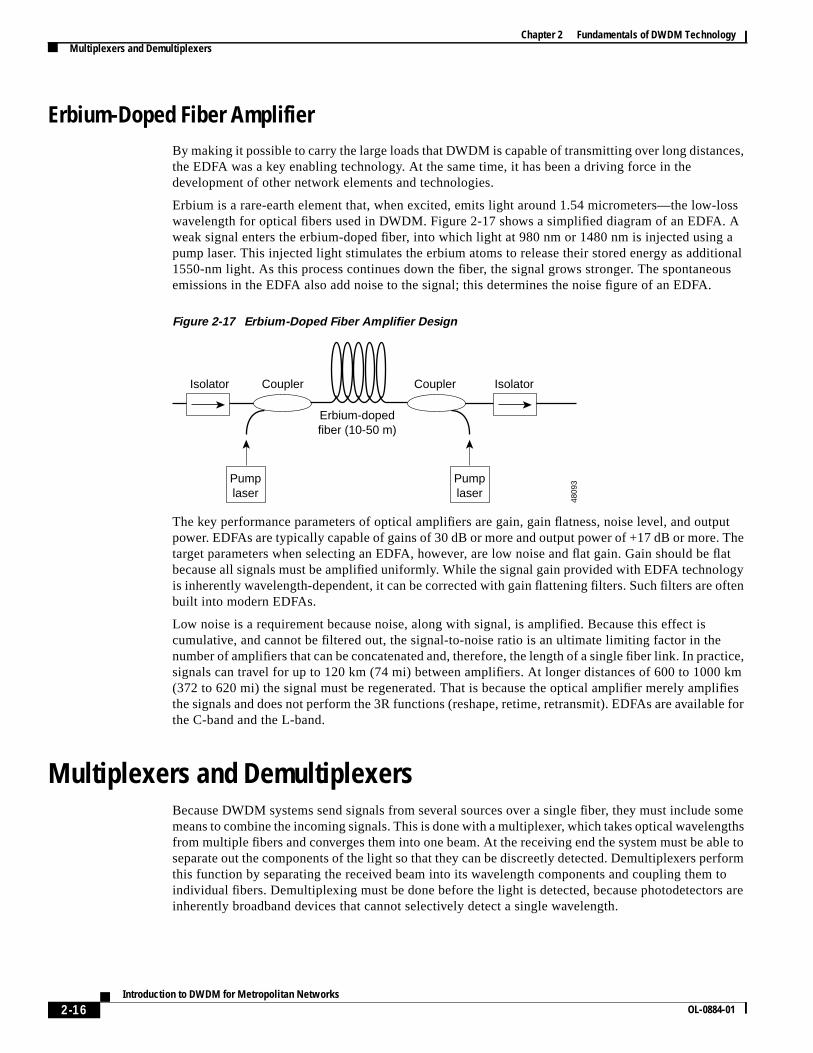
Erbium is a rare-earth element that, when excited, emits light around 1.54 micrometers—the low-losswavelength for optical fibers used in DWDM. Figure 2-17 shows a simplified diagram of an EDFA. Aweak signal enters the erbium-doped fiber, into which light at 980 nm or 1480 nm is injected using apump laser. This injected light stimulates the erbium atoms to release their stored energy as additional1550-nm light. As this process continues down the fiber, the signal grows stronger. The spontaneousemissions in the EDFA also add noise to the signal; this determines the noise figure of an EDFA.
Figure 2-17 Erbium-Doped Fiber Amplifier Design
The key performance parameters of optical amplifiers are gain, gain flatness, noise level, and outputpower. EDFAs are typically capable of gains of 30 dB or more and output power of +17 dB or more. Thetarget parameters when selecting an EDFA, however, are low noise and flat gain. Gain should be flatbecause all signals must be amplified uniformly. While the signal gain provided with EDFA technologyis inherently wavelength-dependent, it can be corrected with gain flattening filters. Such filters are oftenbuilt into modern EDFAs.
Low noise is a requirement because noise, along with signal, is amplified. Because this effect iscumulative, and cannot be filtered out, the signal-to-noise ratio is an ultimate limiting factor in thenumber of amplifiers that can be concatenated and, therefore, the length of a single fiber link. In practice,signals can travel for up to 120 km (74 mi) between amplifiers. At longer distances of 600 to 1000 km(372 to 620 mi) the signal must be regenerated. That is because the optical amplifier merely amplifiesthe signals and does not perform the 3R functions (reshape, retime, retransmit). EDFAs are available forthe C-band and the L-band.
Multiplexers and DemultiplexersBecause DWDM systems send signals from several sources over a single fiber, they must include somemeans to combine the incoming signals. This is done with a multiplexer, which takes optical wavelengthsfrom multiple fibers and converges them into one beam. At the receiving end the system must be able toseparate out the components of the light so that they can be discreetly detected. Demultiplexers performthis function by separating the received beam into its wavelength components and coupling them toindividual fibers. Demultiplexing must be done before the light is detected, because photodetectors areinherently broadband devices that cannot selectively detect a single wavelength.
Pumplaser
Pumplaser
Erbium-dopedfiber (10-50 m)
CouplerIsolator IsolatorCoupler
4809
3
2-17Introduction to DWDM for Metropolitan Networks
OL-0884-01
Chapter 2 Fundamentals of DWDM TechnologyMultiplexers and Demultiplexers
In a unidirectional system (see Figure 2-18), there is a multiplexer at the sending end and a demultiplexerat the receiving end. Two system would be required at each end for bidirectional communication, andtwo separate fibers would be needed.
Figure 2-18 Multiplexing and Demultiplexing in a Unidirectional System
In a bidirectional system, there is a multiplexer/demultiplexer at each end (see Figure 2-19) andcommunication is over a single fiber, with different wavelengths used for each direction.
Figure 2-19 Multiplexing and Demultiplexing in a Bidirectional System
Multiplexers and demultiplexers can be either passive or active in design. Passive designs are based onprisms, diffraction gratings, or filters, while active designs combine passive devices with tunable filters.The primary challenges in these devices is to minimize cross-talk and maximize channel separation.Cross-talk is a measure of how well the channels are separated, while channel separation refers to theability to distinguish each wavelength.
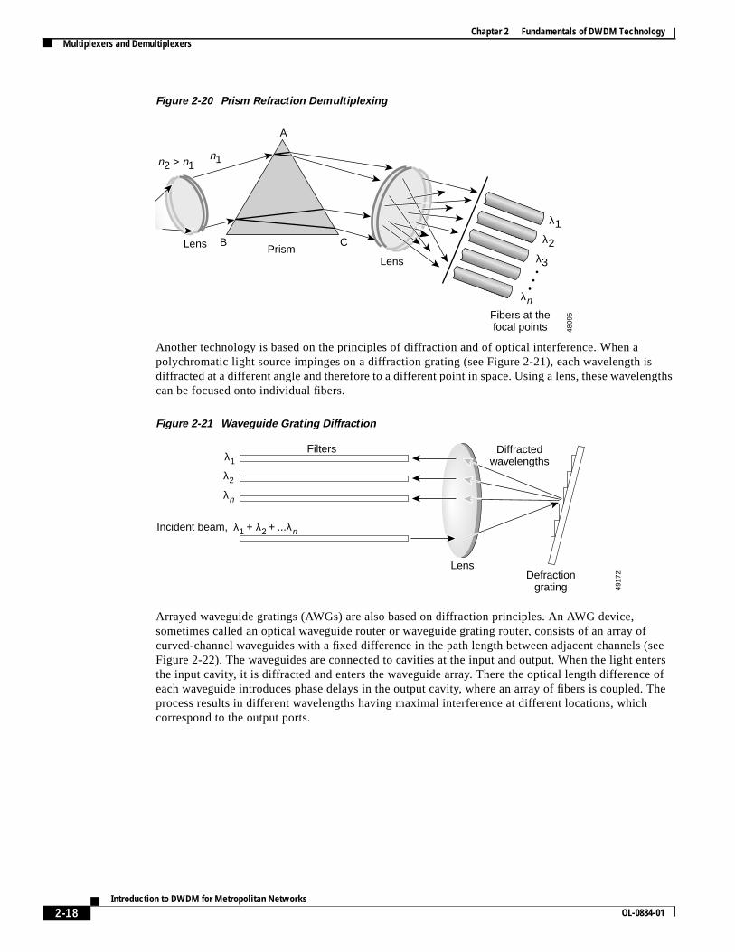
Techniques for Multiplexing and DemultiplexingA simple form of multiplexing or demultiplexing of light can be done using a prism. Figure 2-20demonstrates the demultiplexing case. A parallel beam of polychromatic light impinges on a prismsurface; each component wavelength is refracted differently. This is the “rainbow” effect. In the outputlight, each wavelength is separated from the next by an angle. A lens then focuses each wavelength tothe point where it needs to enter a fiber. The same components can be used in reverse to multiplexdifferent wavelengths onto one fiber.
MUX DEMUX
DEMUX MUX
5118
3
MUX/DEMUX MUX/DEMUX
5118
4
2-18Introduction to DWDM for Metropolitan Networks
OL-0884-01
Chapter 2 Fundamentals of DWDM TechnologyMultiplexers and Demultiplexers
Figure 2-20 Prism Refraction Demultiplexing
Another technology is based on the principles of diffraction and of optical interference. When apolychromatic light source impinges on a diffraction grating (see Figure 2-21), each wavelength isdiffracted at a different angle and therefore to a different point in space. Using a lens, these wavelengthscan be focused onto individual fibers.
Figure 2-21 Waveguide Grating Diffraction
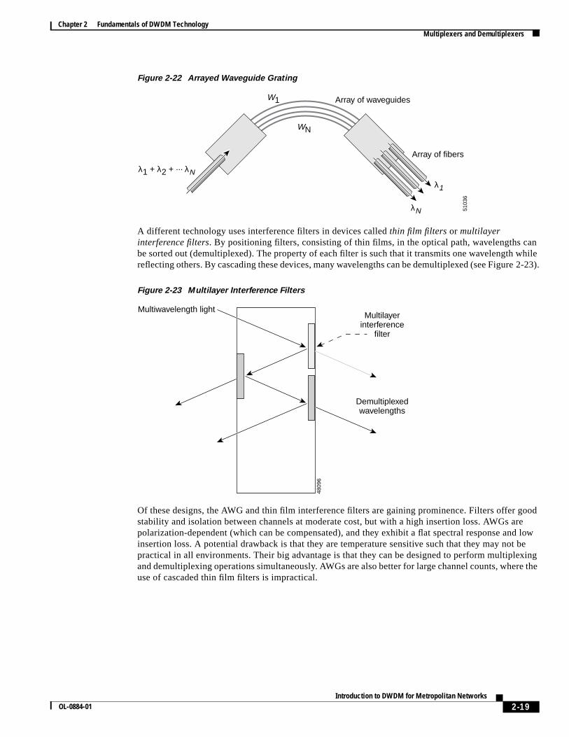
Arrayed waveguide gratings (AWGs) are also based on diffraction principles. An AWG device,sometimes called an optical waveguide router or waveguide grating router, consists of an array ofcurved-channel waveguides with a fixed difference in the path length between adjacent channels (seeFigure 2-22). The waveguides are connected to cavities at the input and output. When the light entersthe input cavity, it is diffracted and enters the waveguide array. There the optical length difference ofeach waveguide introduces phase delays in the output cavity, where an array of fibers is coupled. Theprocess results in different wavelengths having maximal interference at different locations, whichcorrespond to the output ports.
Fibers at thefocal points
PrismLens
Lens
4809
5
A
B C
n2 > n1n1
λ1λ2
λ3
λn
Defractiongrating
Lens
Filters Diffractedwavelengths
λ1 + λ2 + ...λn
λ2
λn
Incident beam,
λ1
4917
2
2-19Introduction to DWDM for Metropolitan Networks
OL-0884-01
Chapter 2 Fundamentals of DWDM TechnologyMultiplexers and Demultiplexers
Figure 2-22 Arrayed Waveguide Grating
A different technology uses interference filters in devices calledthin film filters or multilayerinterference filters. By positioning filters, consisting of thin films, in the optical path, wavelengths canbe sorted out (demultiplexed). The property of each filter is such that it transmits one wavelength whilereflecting others. By cascading these devices, many wavelengths can be demultiplexed (see Figure 2-23).
Figure 2-23 Multilayer Interference Filters
Of these designs, the AWG and thin film interference filters are gaining prominence. Filters offer goodstability and isolation between channels at moderate cost, but with a high insertion loss. AWGs arepolarization-dependent (which can be compensated), and they exhibit a flat spectral response and lowinsertion loss. A potential drawback is that they are temperature sensitive such that they may not bepractical in all environments. Their big advantage is that they can be designed to perform multiplexingand demultiplexing operations simultaneously. AWGs are also better for large channel counts, where theuse of cascaded thin film filters is impractical.
Array of fibers
Array of waveguides
λ1 + λ2 + ... λN
W1
WN
λN
λ1
5103
6
Multiwavelength light
Demultiplexedwavelengths
Multilayerinterference
filter
4809
6
2-20Introduction to DWDM for Metropolitan Networks
OL-0884-01
Chapter 2 Fundamentals of DWDM TechnologyInterfaces to DWDM
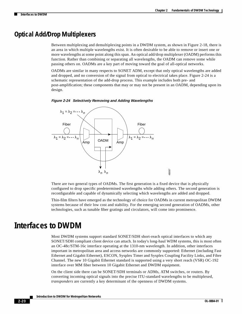
Optical Add/Drop MultiplexersBetween multiplexing and demultiplexing points in a DWDM system, as shown in Figure 2-18, there isan area in which multiple wavelengths exist. It is often desirable to be able to remove or insert one ormore wavelengths at some point along this span. An optical add/drop multiplexer (OADM) performs thisfunction. Rather than combining or separating all wavelengths, the OADM can remove some whilepassing others on. OADMs are a key part of moving toward the goal of all-optical networks.
OADMs are similar in many respects to SONET ADM, except that only optical wavelengths are addedand dropped, and no conversion of the signal from optical to electrical takes place. Figure 2-24 is aschematic representation of the add-drop process. This example includes both pre- andpost-amplification; these components that may or may not be present in an OADM, depending upon itsdesign.
Figure 2-24 Selectively Removing and Adding Wavelengths
There are two general types of OADMs. The first generation is a fixed device that is physicallyconfigured to drop specific predetermined wavelengths while adding others. The second generation isreconfigurable and capable of dynamically selecting which wavelengths are added and dropped.
Thin-film filters have emerged as the technology of choice for OADMs in current metropolitan DWDMsystems because of their low cost and stability. For the emerging second generation of OADMs, othertechnologies, such as tunable fiber gratings and circulators, will come into prominence.
Interfaces to DWDMMost DWDM systems support standard SONET/SDH short-reach optical interfaces to which anySONET/SDH compliant client device can attach. In today's long-haul WDM systems, this is most oftenan OC-48c/STM-16c interface operating at the 1310-nm wavelength. In addition, other interfacesimportant in metropolitan area and access networks are commonly supported: Ethernet (including FastEthernet and Gigabit Ethernet), ESCON, Sysplex Timer and Sysplex Coupling Facility Links, and FibreChannel. The new 10 Gigabit Ethernet standard is supported using a very short reach (VSR) OC-192interface over MM fiber between 10 Gigabit Ethernet and DWDM equipment.
On the client side there can be SONET/SDH terminals or ADMs, ATM switches, or routers. Byconverting incoming optical signals into the precise ITU-standard wavelengths to be multiplexed,transponders are currently a key determinant of the openness of DWDM systems.
OADMAmp Amp
Fiber
λ1 = λ2 = λn
Fiber
λ1 = λ2 = λn
λ1 = λ2 = λn
λn λn 4809
7
2-21Introduction to DWDM for Metropolitan Networks
OL-0884-01
Chapter 2 Fundamentals of DWDM TechnologyOperation of a Transponder Based DWDM System
Within the DWDM system a transponder converts the client optical signal from back to an electricalsignal and performs the 3R functions (see Figure 2-25). This electrical signal is then used to drive theWDM laser. Each transponder within the system converts its client's signal to a slightly differentwavelength. The wavelengths from all of the transponders in the system are then optically multiplexed.In the receive direction of the DWDM system, the reverse process takes place. Individual wavelengthsare filtered from the multiplexed fiber and fed to individual transponders, which convert the signal toelectrical and drive a standard interface to the client.
Figure 2-25 Transponder Functions
Future designs include passive interfaces, which accept the ITU-compliant light directly from anattached switch or router with an optical interface.
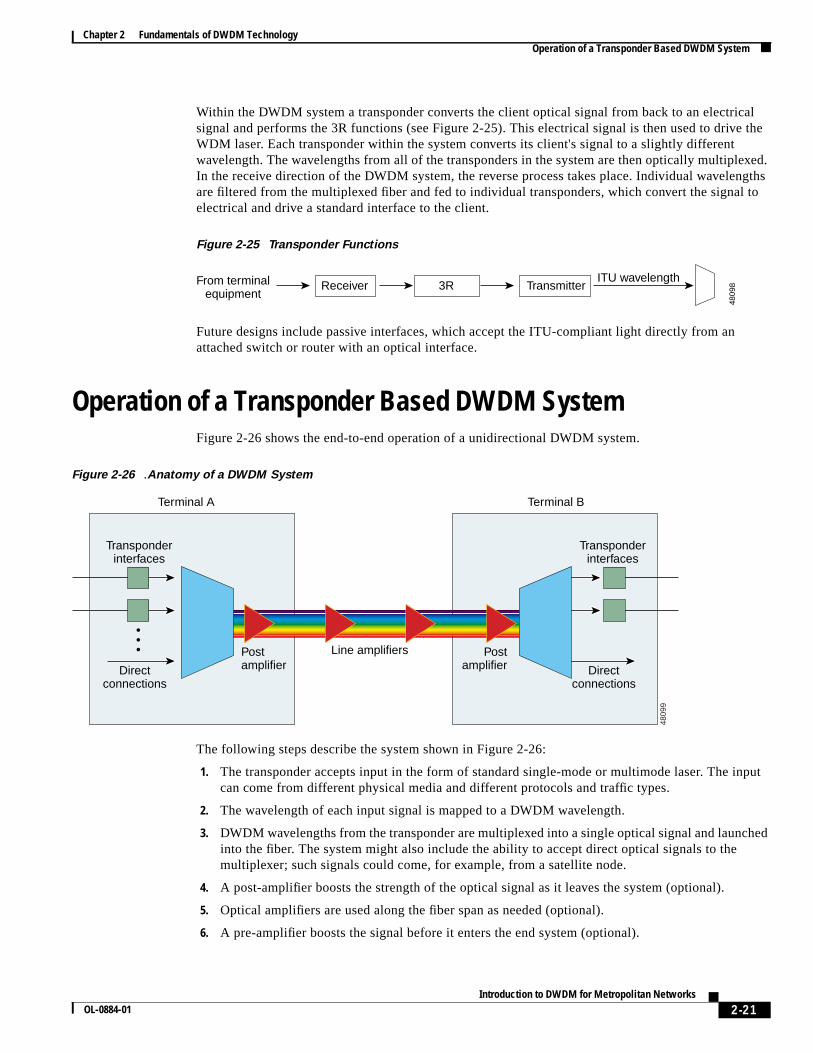
Operation of a Transponder Based DWDM SystemFigure 2-26 shows the end-to-end operation of a unidirectional DWDM system.
Figure 2-26 .Anatomy of a DWDM System
The following steps describe the system shown in Figure 2-26:
1. The transponder accepts input in the form of standard single-mode or multimode laser. The inputcan come from different physical media and different protocols and traffic types.
2. The wavelength of each input signal is mapped to a DWDM wavelength.
3. DWDM wavelengths from the transponder are multiplexed into a single optical signal and launchedinto the fiber. The system might also include the ability to accept direct optical signals to themultiplexer; such signals could come, for example, from a satellite node.
4. A post-amplifier boosts the strength of the optical signal as it leaves the system (optional).
5. Optical amplifiers are used along the fiber span as needed (optional).
6. A pre-amplifier boosts the signal before it enters the end system (optional).
From terminalequipment
ITU wavelengthReceiver Transmitter3R
4809
8
Directconnections
Postamplifier
Postamplifier Direct
connections
Transponderinterfaces
Transponderinterfaces
Line amplifiers
Terminal A Terminal B
4809
9
2-22Introduction to DWDM for Metropolitan Networks
OL-0884-01
Chapter 2 Fundamentals of DWDM TechnologyOperation of a Transponder Based DWDM System
7. The incoming signal is demultiplexed into individual DWDM lambdas (or wavelengths).
8. The individual DWDM lambdas are mapped to the required output type (for example, OC-48single-mode fiber) and sent out through the transponder.