“Fundamentals of IP Networking 2017 Webinar Series” Part 3 IP Routing and Internetworking Fundamentals Wayne M. Pecena, CPBE, CBNE Texas A&M University Educational Broadcast Services – KAMU Public Broadcasting June_2017 IP_Net_Fundamentals-Part-3
Transcript
“Fundamentals of IP Networking 2017 Webinar Series”
Part 3 IP Routing and Internetworking Fundamentals
Wayne M. Pecena, CPBE, CBNE Texas A&M University
Educational Broadcast Services – KAMU Public Broadcasting
June_2017 IP_Net_Fundamentals-Part-3
“Fundamentals of IP Networking 2017 Webinar Series” Advertised Presentation Scope
Part 1- Introduction to IP Networking Standards & the Physical Layer Part 2 - Ethernet Switching Fundamentals and Implementation Part 3 - IP Routing and Internetworking Fundamentals Continuing The Fundamentals of IP Networking Series, Part 3 of the webinar series focuses upon understanding IP routing and applying concepts in practical inter-networking by exploring the foundation and protocols of Layer 3 of the OSI model. Specific topics to be covered include understanding the role of routed protocols, IP addressing (subnetting), IP routing protocol section, and the role of layer 3 protocols such as ICMP and ARP. Part 4 - Building a Segmented IP Network Focused On Performance & Security - July 25 Part 5 - Cybersecurity Fundamentals & Securing the Network - August 29
2
Today’s Outline:
• Takeaway Review From Part 2
• The Network Layer
• Layer 3 Protocols – Overview
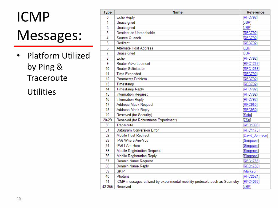
– ICMP Focus
• Routing and the Routing Protocol – Overview
– Selection
• The IP Address – IPv4 Focus
– IPv6 Introduction
• Takeaways, References, Questions, and Maybe Some Answers
3
Part 2 - Takeaway Point Review • The Ethernet Switch is the Fundamental LAN Building Block
• VLANs Allow a Common Physical Infrastructure to Support Multiple Isolated Networks or Subnets
• Each Network, Subnet, or VLAN is a Broadcast Domain With a Unique IP Address Scheme
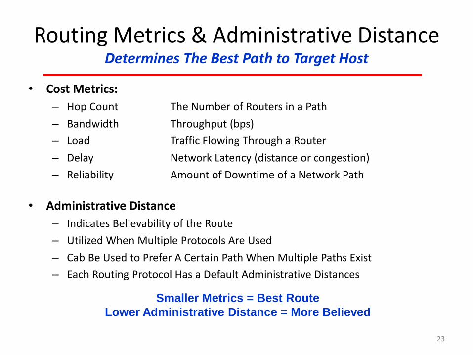
Routing • Routing is Simply the Moving Packets Between Different
Networks (Subnets or Broadcast Domains) by A “Routing” Protocol Utilizing a “Routed” Protocol by Determining the “Best Route” to the Destination Network.
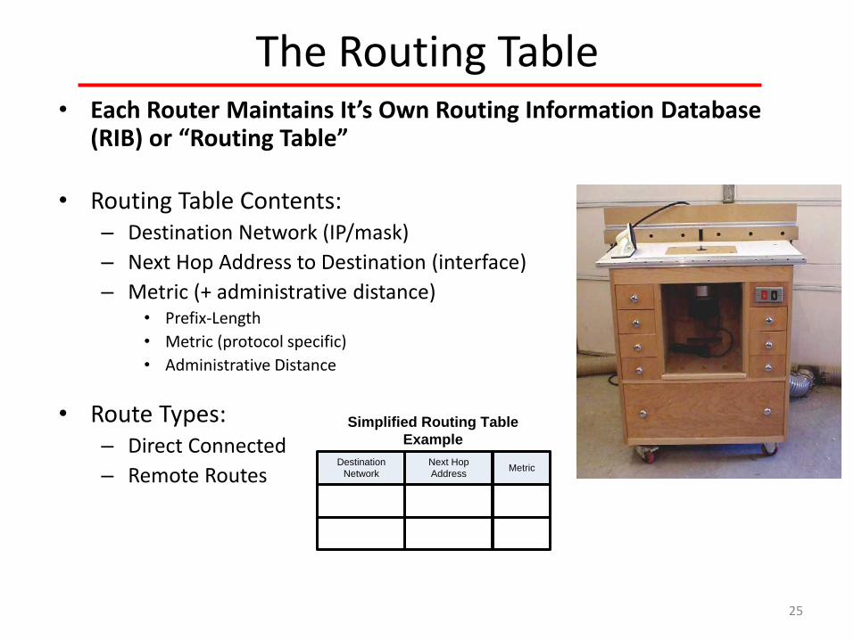
• OSI Model Layer 3 Defined Inter-Networking Process
– Destination Address Lookup in Routing Table (RIB)
– Determine Egress Interface to Forward Packet To
– Re-Encapsulates Layer 2 Header Information
20
Routing Types • Static Routing
– Appropriate for Small & Simple Networks – Minimal Router CPU/Memory – No Routing Update Overhead – Appropriate for Stable Networks – Often Used in “Stub” Networks – Human Intervention / Administration Required Yy
• Dynamic Routing – Appropriate for Changing Topology Environments
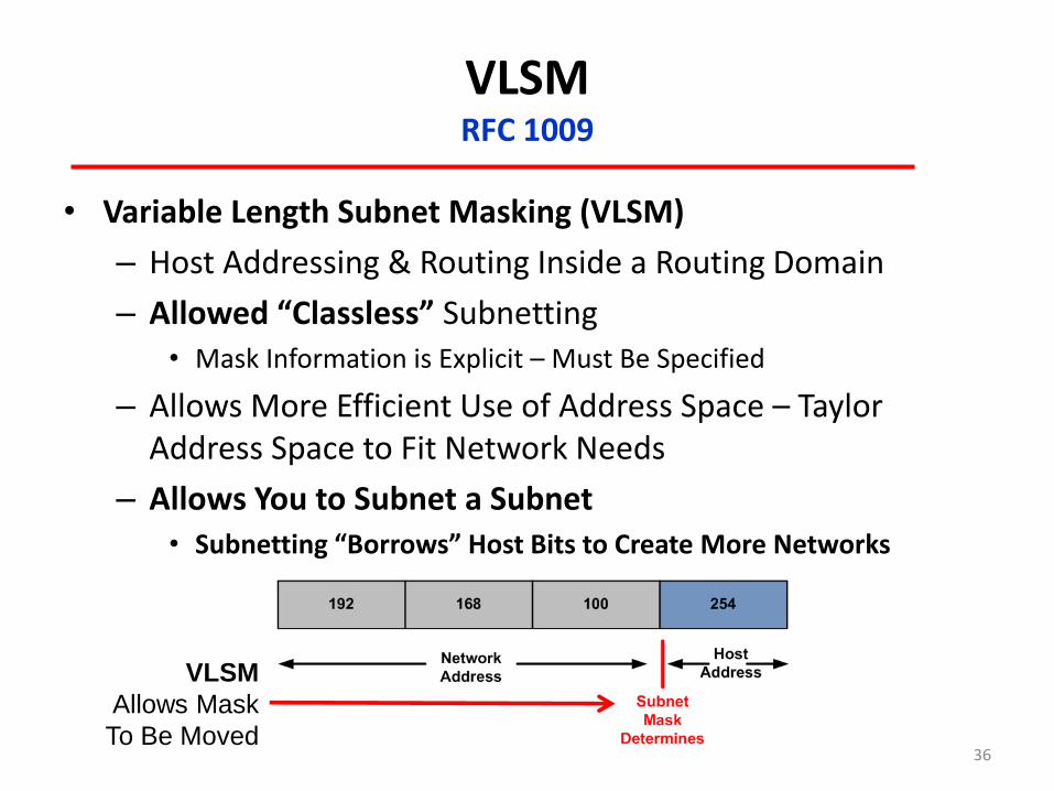
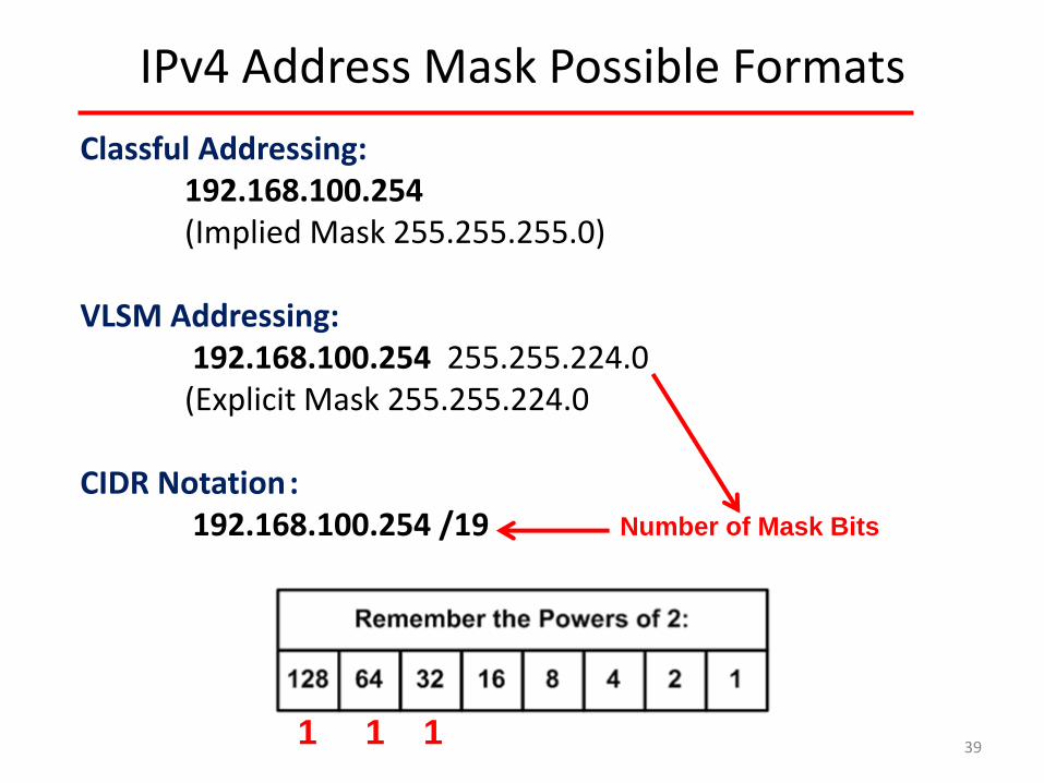
IPv4 Address Subnet Mask Example “VLSM” - Each IP Address Must Have a Subnet Mask to Define the Network and the Host
32 Bit Subnet Mask
Expressed in Decimal as (4) 8-bit Octets using “Doted Decimal Notation”
IP Address: 192.168.100.254 /19
192.168.100.254 /19 or 255.255.224.0
11000000.10101000.00000001.01100100
11111111.11111111.11100000.00000000Network Host
40
IPv4 Address Block Size Based Upon 2n
41
2n
128
64
32
16
8
4
2
1 LSB
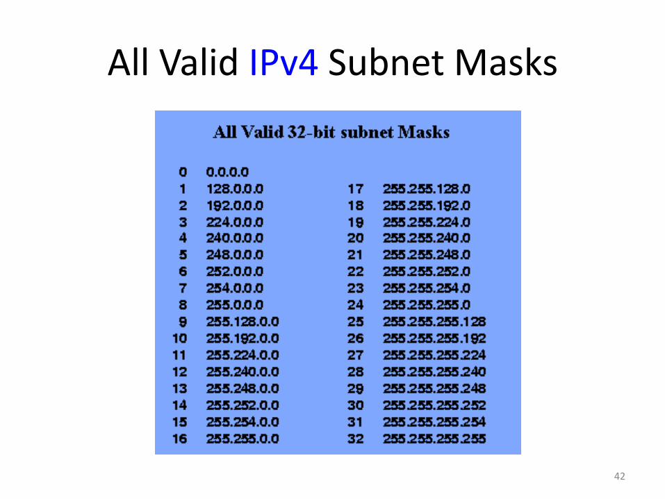
All Valid IPv4 Subnet Masks
42
The First & Last IP Address of a Network is Not Useable! • The First Address = Network Address
• The Last Address = Broadcast Address
126 “Useable”
Hosts
/25
62 “Useable”
Hosts
30 “Useable”
Hosts
/26 /27
Network Address
Broadcast Address
Network Address Network Address
Broadcast Address
Broadcast Address
12
8 IP
Ad
dre
sses
32
IP A
dd
ress
es
64
IP A
dd
ress
es
Gateway Address
Gateway Address
43
Private IPv4 Address Space • RFC 1918 Established “Private” Address Space
– Class A: 10.0.0.0 to 10.255.255.255
– Class B: 172.16.0.0 to 172.31.255.255
– Class C: 192.168.0.0 to 192.168.255.255
• Private Address Space or “1918 Space”: – Private IP Address Space Is NOT Routable to the Global Internet
– Widely Used: • Hide Host IP Address “Security by Obscurity”
• Minimize Public IP Use
– May Be Translated With Network Address Translation (NAT) Techniques: • One-One Network Address Translation (NAT) – Static & Dynamic
• Many-One Port Address Translation (PAT)
44
Network Address Translation – NAT RFC 3022
Inside
Network
(private)
Outside
Network
RFC 1918
Addressed Hosts
Public
Address
Space
(Usually)
Gateway Router
w/ NAT Services
• NAT Allows a Host Without a Valid Public IP Address to Communicate With a Host That Has a Public IP Address by Simply Changing the IP Addresses as Packet Passes Through the NAT Device
• Why Use?
– Conserve Public IPv4 Address Space
– Security by Obscurity (hide actual host IP address) - “Questionable Value”
• NAT Types:
– Static – One-to-One Translation
– Dynamic – Pool of Public Addresses Made Available to Outbound Traffic Client Traffic
– NAT Overloading or Port Address Translation (PAT) – Translates to a Single Public IP by Use of a Unique Port Number
45
Special Use “Reserved” IPv4 Address Space RFC 5735
• 0.0.0.0/8 Network Address “This Network or Wire Address”
• 10.0.0.0/8 Private IP Address Space (RFC 1918)
• 127.0.0.0/8 Loopback Address
• 169.254.0.0/16 IETF Zero Configuration Address Space (RFC 3927) Automatic Private IP Addressing (APIPA)
• 172.16.0.0/16 Private IP Address Space (RFC 1918)
• 192.168.0.0/16 Private IP Address Space (RFC 1918)
• 224.0.0.0/4 Multicast Address Space
• 240.0.0.0/4 Experimental Address Space
• 255.255.255.255/32 Broadcast Address
Yields About 3.7 Billion “Useable” IPv4 Addresses
46
The IPv4 “Loop Back” Address
• What is Special About 127.0.0.1 ?
– Known as a “Loop-Back” Address
– Actually Any 127.0.0.0/8 Address Works OR the Range of 127.0.0.1 to 127.255.255.255
• Useful For to Test Local IP Stack and Network Adapter
47
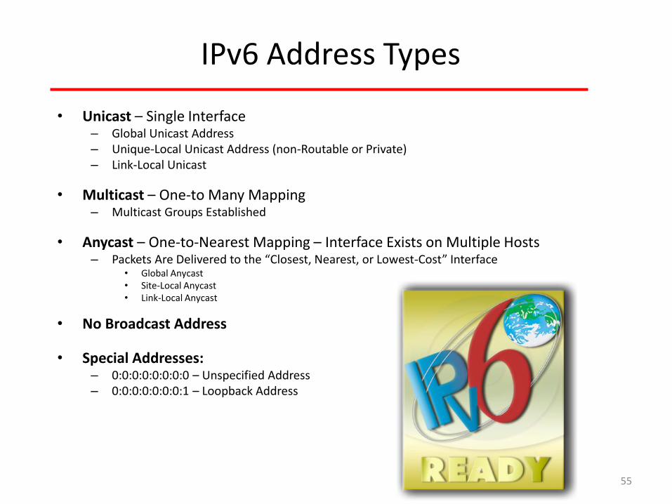
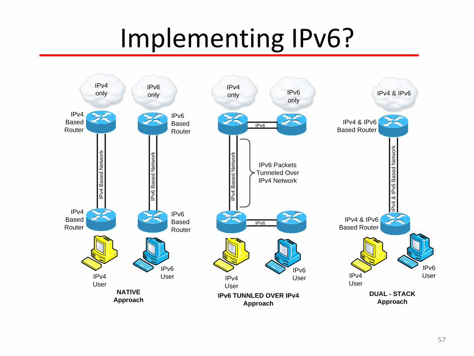
Let’s Think About IPv6
48
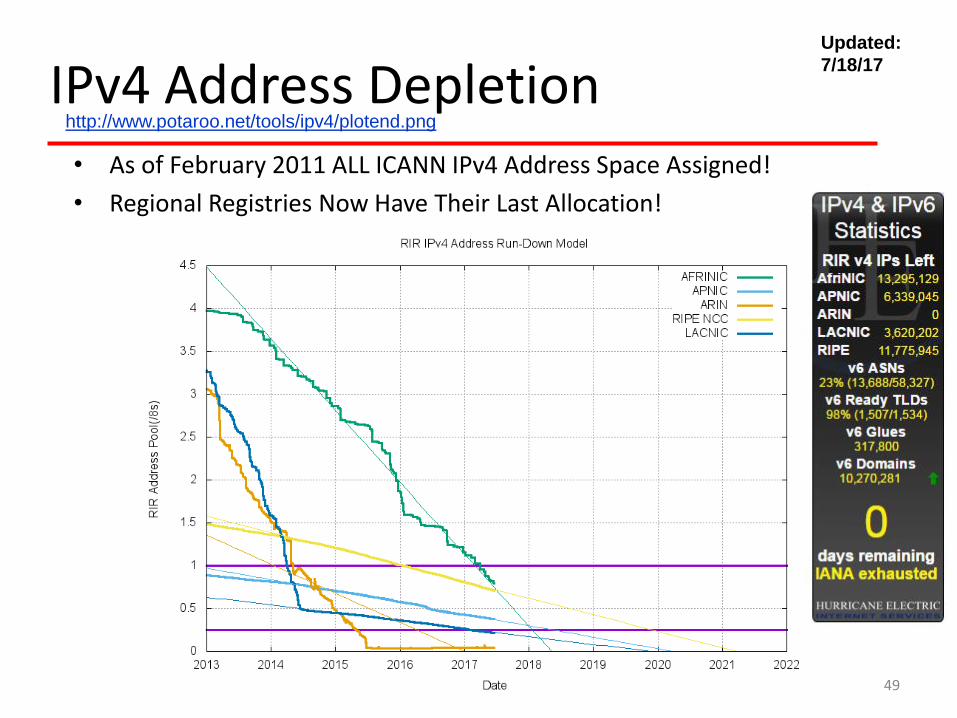
IPv4 Address Depletion • As of February 2011 ALL ICANN IPv4 Address Space Assigned!
• Regional Registries Now Have Their Last Allocation!
What Happened to Version 5 or IPv5 of the Internet Protocol?
“IPv5 Simply Does Not Exist!” Version 5 was intentionally skipped to avoid confusion, or at least to rectify it. The problem with version 5 relates to an experimental TCP/IP protocol called the Internet Stream Protocol, Version 2, originally defined in RFC 1190. This protocol was originally seen by some as being a peer of IP at the Internet Layer in the TCP/IP architecture and these packets were assigned IP version 5 to differentiate them from “normal” IPv4 packets. This protocol never went anywhere, but to be absolutely sure that there would be no confusion, version 5 was skipped over in favor of version 6.”
"Who the hell knew how much address space we needed for an experiment?“ “The experiment has not ended”
“Vint” Cerf comments on his & colleagues 1977 decision to use 32-bit IP Numbers
65
TAKEAWAYS, REFERENCES, & QUESTIONS
66
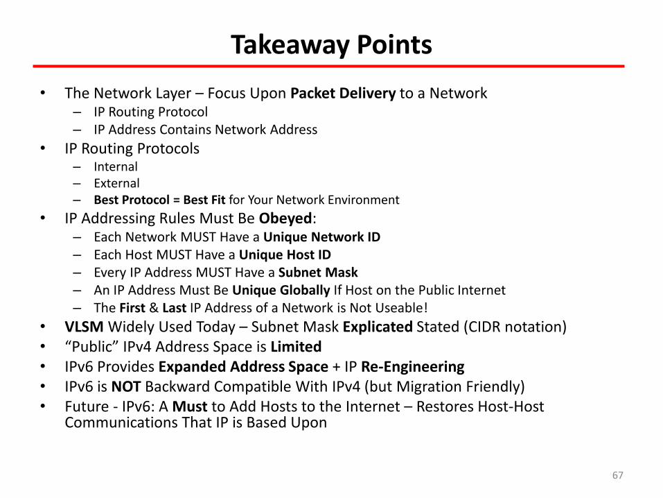
Takeaway Points
• The Network Layer – Focus Upon Packet Delivery to a Network – IP Routing Protocol – IP Address Contains Network Address
• IP Routing Protocols – Internal – External – Best Protocol = Best Fit for Your Network Environment
• IP Addressing Rules Must Be Obeyed: – Each Network MUST Have a Unique Network ID – Each Host MUST Have a Unique Host ID – Every IP Address MUST Have a Subnet Mask – An IP Address Must Be Unique Globally If Host on the Public Internet – The First & Last IP Address of a Network is Not Useable!
• VLSM Widely Used Today – Subnet Mask Explicated Stated (CIDR notation) • “Public” IPv4 Address Space is Limited • IPv6 Provides Expanded Address Space + IP Re-Engineering • IPv6 is NOT Backward Compatible With IPv4 (but Migration Friendly) • Future - IPv6: A Must to Add Hosts to the Internet – Restores Host-Host
Communications That IP is Based Upon
67
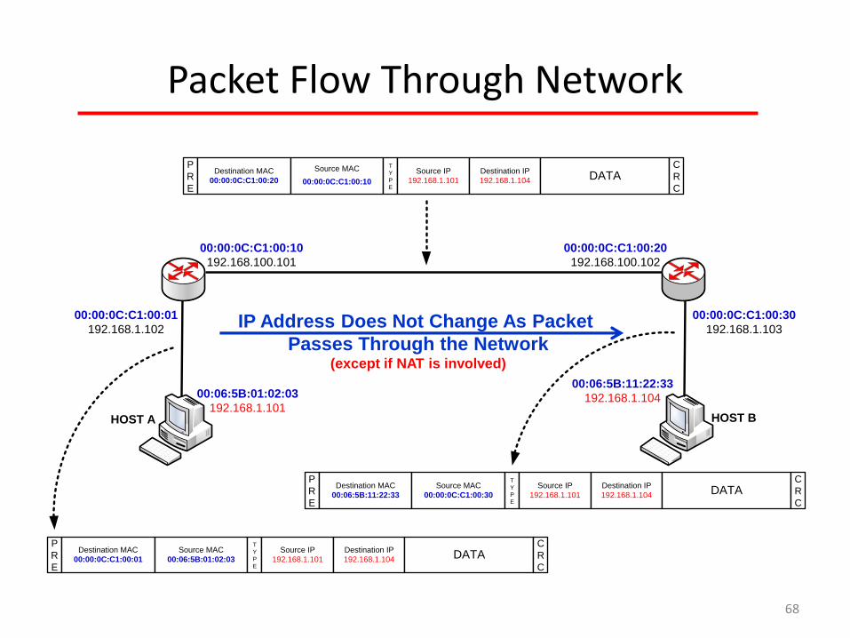
Packet Flow Through Network
00:06:5B:01:02:03
192.168.1.101
00:06:5B:11:22:33
192.168.1.104
00:00:0C:C1:00:01
192.168.1.102
00:00:0C:C1:00:30
192.168.1.103
00:00:0C:C1:00:20
192.168.100.102
00:00:0C:C1:00:10
192.168.100.101
Destination MAC
00:00:0C:C1:00:20
Source MAC
00:00:0C:C1:00:10
Source IP
192.168.1.101
Destination IP
192.168.1.104 DATAP
R
E
C
R
C
T
Y
P
E
Destination MAC
00:00:0C:C1:00:01
Source MAC
00:06:5B:01:02:03
Source IP
192.168.1.101
Destination IP
192.168.1.104 DATAP
R
E
C
R
C
T
Y
P
E
Destination MAC
00:06:5B:11:22:33
Source MAC
00:00:0C:C1:00:30
Source IP
192.168.1.101
Destination IP
192.168.1.104 DATAP
R
E
C
R
C
T
Y
P
E
HOST A HOST B
IP Address Does Not Change As Packet
Passes Through the Network (except if NAT is involved)