United States Nuclear Regulatory Commission Official Hearing Exhibit In the Matter of: Entergy Nuclear Operations, Inc. (Indian Point Nuclear Generating Units 2 and 3) ASLBP #: 07-858-03-LR-BD01 Docket #: 05000247 | 05000286 Exhibit #: Identified: Admitted: Withdrawn: Rejected: Stricken: Other: NYS000339-00-BD01 10/15/2012 10/15/2012 NYS000339 Submitted: December 22, 2011 EXCERPT c.\.t.pr.RREGU<.q" < 0 ", : -' ......... 1-- ? '" ... * .... Gary S. Was Fundamentals of Radiation Materials Science Metals and Alloys With 381 Figures Springer OAGI0000607_00001
Transcript
United States Nuclear Regulatory Commission Official Hearing Exhibit
In the Matter of: Entergy Nuclear Operations, Inc. (Indian Point Nuclear Generating Units 2 and 3)
Fundamentals of Radiation Materials Science Metals and Alloys
With 381 Figures
~ Springer
OAGI0000607 _00001
Gary S. Was Nuclear Engineering and Radiological Sciences Materials Science and Engineering University of Michigan 1921 Cooley Bldg. 2355 Bonisteel Blvd. Ann Arbor, MI 48109-2104, USA e-mail: [email protected]
Library of Congress Control Number: 2007922926
ISBN 978-3-540-49471-3 Springer Berlin Heidelberg New York
This work is subject to copyright. All rights are reserved, whether the whole or part of the material is concerned, specifically the rights of translation, reprinting, reuse of illustrations, recitation, broadcasting, reproduction on microfilm or in any other way, and storage in data banks. Duplication of this pUblication or parts thereof is permitted only under the provisions of the German Copyright Law of September 9, 1965, in its current version, and permission for use must always be obtained from Springer. Violations are liable for prosecution under the German Copyright Law.
Springer is a part of Springer Science+Business Media
The use of general descriptive names, registered names, trademarks, etc. in this publication does not imply, even in the absence of a specific statement, that such names are exempt from the relevant protective laws and regulations and therefore free for general use.
Typesetting and production: LE-T]3X Jelonek, Schmidt & V&kler GbR, Leipzig Cover design: eStudio Calamar S.L.. F. Steinen-Broo, Girona, Spain
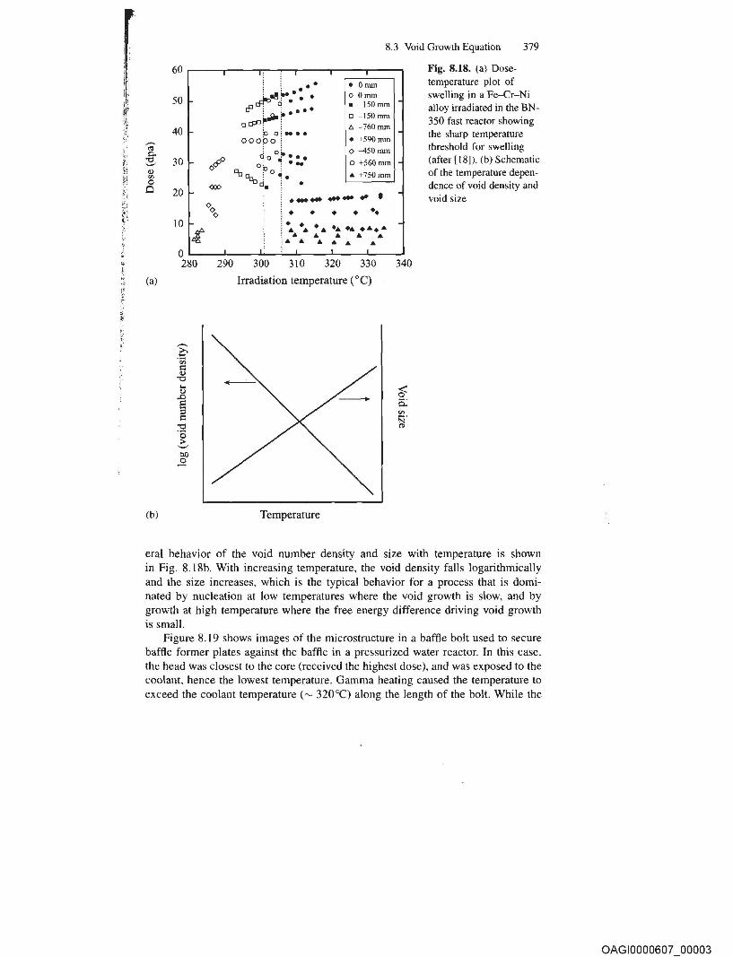
Fig. 8.18. (a) Dosetemperature plot of swelling in a Fe-Cr-Ni aHoy irradiated in the BN-350 fast reactor showing the sharp temperature threshold for sweJling (after [18]). (b) Schematic of the temperature dependence of void density and void size
eral behavior of the void number density and size with temperature is shown in Fig. 8.18b. With increasing temperature, the void density falls logarithmically and the size increases, which is the typical behavior for a process that is dominated by nucleation at low temperatures where the void growth is slow, and by growth at high temperature where the free energy difference driving void growth is small.
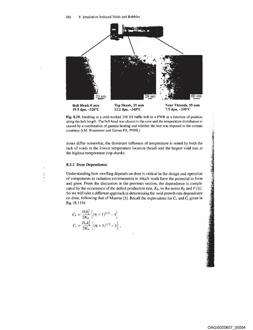
Figure 8.19 shows images of the microstructure in a baffle bolt used to secure baffle former plates against the baffle in a pressurized water reactor. In this case, the head was closest to the core (received the highest dose), and was exposed to the coolant, hence the lowest temperature. Gamma heating caused the temperature to exceed the coolant temperature ('" 320°C) along the length of the bolt. While the
OAGI0000607 00003
380 8 Irradiation-Induced Voids and Bubbles
Bolt Head, 0 mm 19.5 dpa, -320°C
Top Shank, 25 mm 12.2 dpa, -340°C
Near Threads, 55 mm 7.5 dpa, -330°C
Fig. 8.19. Swelling in a cold-worked 316 SS baffle bait in a PWR as a function of position along the bolt length. The bolt head was closest to the core and the temperature distribution is caused by a combination of gamma heating and whether the bolt was exposed to the coolant (courtesy S.M. Bruemmer and Garner FA, PNNL)
doses differ somewhat, the dominant influence of temperature is noted by both the lack of voids in the lowest temperature location (head) and the largest void size at the highest temperature (top shank).
8.3.2 Dose Dependence
Understanding how swelling depends on dose is critical in the design and operation of components in radiation environments in which voids have the potential to form and grow. From the discussion in the previous section, the dependence is complicated by the occurrence of the defect production rate, Ko, in the terms Ro and F( 1'/). So we will take a different approach in determining the void growth rate dependence on dose, following that of Mansur (5]. Recall the expressions for Cv and Cj given in Eq. (8.119):
OAGI0000607 00004
Nomenclature 423
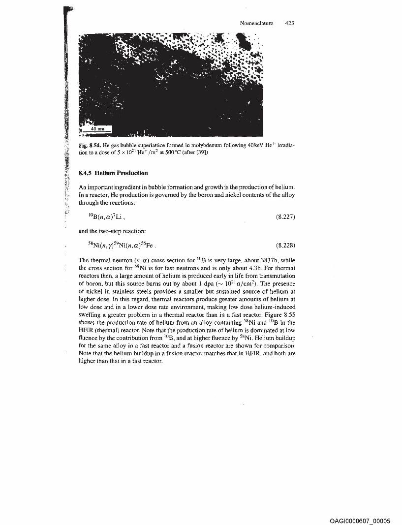
Fig. 8.54. He gas bubble superlattice formed in molybdenum following 40keV He+ irradiation to a dose of 5 x 10²¹ He+ 1m2 at 500°C (after [39])
8.4.5 Helium Production
An important ingredient in bubble formation and growth is the production of helium. In a reactor, He production is governed by the boron and nickel contents of the alloy through the reactions:
(8.227)
and the two-step reaction:
(8.228)
The thermal neutron (n, a) cross section for lOB is very large, about 3837b, while the cross section for 59Ni is for fast neutrons and is only about 4.3b. For thermal reactors then, a large amount of helium is produced early in life from transmutation of boron, but this source bums out by about I dpa ("" 1021 n/cm2). The presence of nickel in stainless steels provides a smaller but sustained source of helium at higher dose. In this regard, thermal reactors produce greater amounts of helium at low dose and in a lower dose rate environment, making low dose helium-induced swelling a greater problem in a thermal reactor than in a fast reactor. Figure 8.55 shows the production rate of helium from an alloy containing 58Ni and lOB in the HFIR (thermal) reactor. Note that the production rate of helium is dominated at low fluence by the contribution from lOB, and at higher ftuence by 58Ni. Helium buildup for the same alloy in a fast reactor and a fusion reactor are shown for comparison. Note that the helium buildup in a fusion reactor matches that in HFIR, and both are higher than that in a fast reactor.
OAGI0000607 00005
15 Environmentally Assisted Cracking of Irradiated Metals and Alloys
A growing concern for electric power utilities worldwide has been the degradation of core components in nuclear power reactors, which provide approximately 17% of the world's electric power production. Service failures have occurred in boiling water reactor (BWR) core components and, to a somewhat lesser extent, in pressurized water reactor (PWR) core components consisting of iron and nickel-base stainless alloys that have achieved a significant neutron fluence in environments that span oxygenated to hydrogenated water at 270-340"C. Because cracking susceptibility depends on many factors, such as alloy composition and microstructure, stress, radiation, and the environment, the failure mechanism has been termed irradiationassisted stress corrosion cracking (IASCC). Initially, the affected components were either relatively small (bolts, springs, etc.) or those designed for replacement (fuel rods, control blades, or instrumentation tubes). Since these early observations, many more structural components.(PWR baffle bolts and BWR core shrouds) have been identified to be susceptible to IASCC. Recent reviews [1, 2, 3, 4, 5] describe the current knowledge related to IASCC service experience and laboratory investigations and highlight the limited amount of well-controlled experimentation that exists on well-characterized materials.
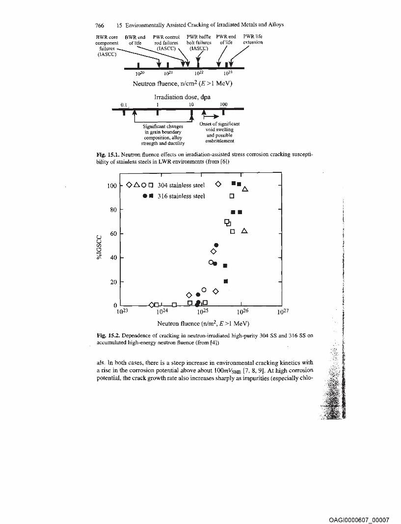
The importance of neutron fluence on IASCC has been well-established (Fig. 15.1). Intergranular (IG) SCC is promoted in austenitic stainless steels as a critical pseudo-threshold fluence is exceeded. The dose to cracking is referred to as a pseudo-threshold because the value depends on the environmental and material parameters. Cracking is observed in BWR oxygenated water at fluences above about 2-5 x 10²⁰ njcm2 (E > 1 MeV), which corresponds to about 0.3-0.7 displacements per atom (dpa) (Fig. 15.2). While the fiuence dependence on cracking is not strong, cracking does occur during ex situ, slow-strain-rate SCC testing of stainless steels irradiated in core. The occurrence of cracking in post-irradiation tests indicates that persistent radiation effects (material changes) are primarily responsible for IASCC susceptibility, although in situ effects like radiation creep relaxation of weld residual stresses and increased stress from differential swelling can be important. In fact, IASCC only occurs with the confluence of irradiation and an aggressive environment. If either is absent, cracking is either eliminated or greatly reduced.
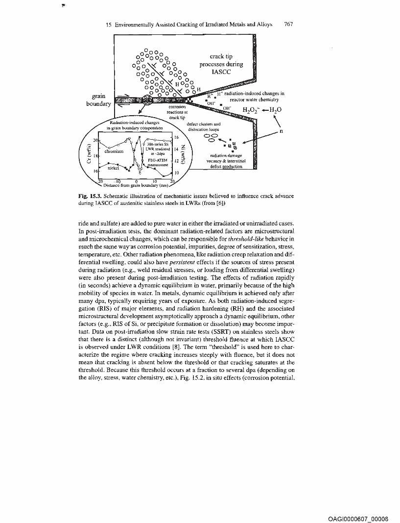
IASCC can be categorized into radiation effects on (1) water chemistry (radiolysis), and (2) material properties, as summarized in Fig. 15.3. The cracking response to changes in water chemistry is similar for both irradiated and unirradiated materi-
OAGI0000607 00006
766 IS Environmentally Assisted Cracking of Irradiated Metals and Alloys
BWR core BWR end PWR control PWR baffle PWR end PWR life component oflife rod failures bolt failures of life extension
I.L r.il=o ~) '\. (IASCC)
(IASCC) L:! .--.. ( 1020 1021 1022 1023
Neutron fluence, nlcm2 (E > 1 MeV)
Irradiation dose, dpa 0.1 1 10 100
i fL..-__ i _---'1 ;:::;: i Onset of significant
void swelling and possible
embrittlement
Significant changes in grain boundary composition, alloy
strength and ductility
Fig. 15.1. Neutron fluence effects on irradiation-assisted stress corrosion cracking susceptibility of stainless steels in LWR environments (from [6])
Fig. 15.2. Dependence of cracking in neutron-irradiated high-purity 304 SS and 316 SS on accumulated high-energy neutron fluence (from [4])
als. In both cases, there is a steep increase in environmental cracking kinetics with a rise in the corrosion potential above about 100mVSHE [7, 8, 9]. At high corrosion potential, the crack growth rate also increases sharply as impurities (especially chlo-
OAGI0000607 00007
15 Environmentally Assisted Cracking of Irradiated Metals and Alloys 767
grain boundary
crack tip processes during
IASCC
~ •• I~~~;i~~r~1~H~ radiation-induced changes in ~ reactor water chemistry
dislocation loops
00 0-...·
.~~ •
radiation damage vacancy & interstitial
defect
n
Fig. 15.3. Schematic illustration of mechanistic issues believed to influence crack advance during IASCC of austenitic stainless steels in LWRs (from [6])
ride and sulfate) are added to pure water in either the irradiated or unirradiated cases. In post-irradiation tests, the dominant radiation-related factors are microstructural and microchemical changes, which can be responsible for threshold-like behavior in much the same waY'as corrosion potential, impurities, degree of sensitization, stress, temperature, etc. Other radiation phenomena, like radiation creep relaxation and differential swelling, could also have persistent effects if the sources of stress present during radiation (e.g., weld residual stresses, or loading from differential swelling) were also present during post-irradiation testing. The effects of radiation rapidly (in seconds) achieve a dynamic equilibrium in water, primarily because of the high mobility of species in water. In metals, dynamic equilibrium is achieved only after many dpa, typically requiring years of exposure. As both radiation-induced segregation (RIS) of major elements, and radiation hardening (RH) and the associated microstructural development asymptotically approach a dynamic equilibrium, other factors (e.g., RIS of Si, or precipitate formation or dissolution) may become important. Data on post-irradiation slow strain rate tests (SSRT) on stainless steels show that there is a distinct (although not invariant) threshold fluence at which IASCC is observed under LWR conditions [8]. The term "threshold" is used here to characterize the regime where cracking increases steeply with fluence, but it does not mean that cracking is absent below the threshold or that cracking saturates at the threshold. Because this threshold occurs at a fraction to several dpa (depending on the alloy, stress, water chemistry, etc.), Fig. 15.2, in situ effects (corrosion potential,
OAGI0000607 00008
r !
15.3 Service and Laboratory Observations of Irradiation Effects on see 797
15.3 Service and Laboratory Observations of Irradiation Effects on see 15.3.1 Austenitic Alloys
A historical perspective of IASCC service experience is instructive,· as the phenomenon extends back to the 1960s, and the early observations and conclusions projected an accurate image of the important characteristics, generic nature, and broad relevance to plant components. As with other instances of environmental cracking, occasional early observations pointed the way toward a growing incidence with time and neutron fluence. IASCC was first reported in the early 1960s [1, 7, 20] and involved intergranular cracking of stainless steel fuel cladding. The findings and conclusions were that intergranular cracking morphology predominated, with initiation of multiple cracks occurring from the waterside. By contrast, only ductile, transgranular cracking was observed in post-irradiation mechanical tests performed in inert environments and at various temperatures and strain rates. Grain boundary carbide precipitation was generally not observed by optical or transmission electron microscopy (although pre-existing thermal sensitization was present in some cases). A correlation between time-to-failure and stress level was reported, with failure occurring first in thin-walled rods with small fuel-to-cladding gaps, where swelling strains were largest. The· highest incidence of cracking occurred in peak heat flux regions, corresponding to the highest fluence and the greatest fuel-cladding interaction (highest stresses and strains). Similar stainless steel cladding in PWR service exhibited fewer instances of intergranular failure. At that time the PWR failures were attributed to off-chemistry conditions or stress rupture.
IASCC has since been observed in a growing number of other stainless steel (and nickel alloy) core components, such as neutron source holders in 1976 and control rod absorber tubes in 1978 [1]. Instrument dry tubes and control blade handles and sheaths, which are subject to very low stresses also cracked, although generally in creviced locations and at higher fluences [5]. Following an initial trickle of failures in the most susceptible components, numerous incidents of IASCC have been observed since the early 1990s, perhaps most notably in BWR core shrouds [1,7,20,29] and PWR baffle bolts [34, 35].
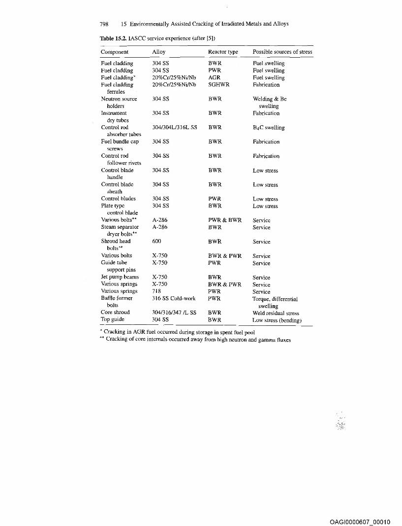
Table 15.2 presents a broad summary of reported failures of reactor internal components, showing that IASCC is not confined to a particular reactor design. For example, stainless steel fuel cladding failures were reported in early commercial PWRs and in PWR test reactors. At the West Milton PWR test loop, intergranular failure of vacuum annealed type 304 stainless steel fuel cladding was observed in 316"C ammoniated water (pH 10) when the cladding was stressed above yield. Similarly, IASCC was observed in creviced stainless steel fuel element ferrules in the Winfrith SGHWR, a 100MWe plant in which light water is boiled within pressure tubes, giving rise to a coolant chemistry similar to other boiling water reactor designs.
Reactor type comparisons were also made in swelling tube tests performed in the core of a BWR and a PWR on a variety of commercial and high purity heats of
OAGI0000607 00009
798 IS Environmentally Assisted Cracking of Irradiated Metals and Alloys
Table 15.2. IASCC service experience (after [S])
Component Alloy Reactor type Possible sources of stress
dry tubes Control rod 304/304L1316L SS BWR B4C swelling
absorber tubes Fuel bundle cap 304 SS BWR Fabrication
screws Control rod 304 SS BWR Fabrication
follower rivets Control blade 304SS BWR Low stress
handle Control blade 304 SS BWR Low stress
sheath Control blades 304 SS PWR Low stress Plate type 304 SS BWR Low stress
control blade Various bolts" A-286 PWR&BWR Service Steam separator A-286 BWR Service
dryer bolts" Shroud head 600 BWR Service
bolts" Various bolts X-7S0 BWR&PWR Service Guide tube X-7S0 PWR Service
support pins Jet pump beams X-7S0 BWR Service Various springs X-7S0 BWR&PWR Service Various springs 718 PWR Service Baffle former 316 SS Cold-work PWR Torque, differential
bolts swelling Core shroud 304/316/347 IL SS BWR Weld residual stress Top guide 304 SS BWR Low stress (bending)
, Cracking in AGR fuel occurred during storage in spent fuel pool " Cracking of core internals occurred away from high neutron and gamma fluxes
OAGI0000607 00010
15.3 Service and Laboratory Observations of Irradiation Effects on SCC 799
types 304, 316 and 348 stainless steel and Alloys X -7 50, 718 and 625. Swelling was controlled by varying the mix of Al203 and B4C within the tubes; the latter swells as neutrons transmute B to He. Nominally identical strings of specimens were inserted into the core in place of fuel rods. The distinction in the IASCC response between the two reactor types was small. While the available data clearly support a linkage between IASCC in BWRs and PWRs, it is clear that the elevated corrosion potential in BWRs accelerates SCC, and to a lesser extent, the generally higher flux and temperature in PWRs also accelerates SCC.
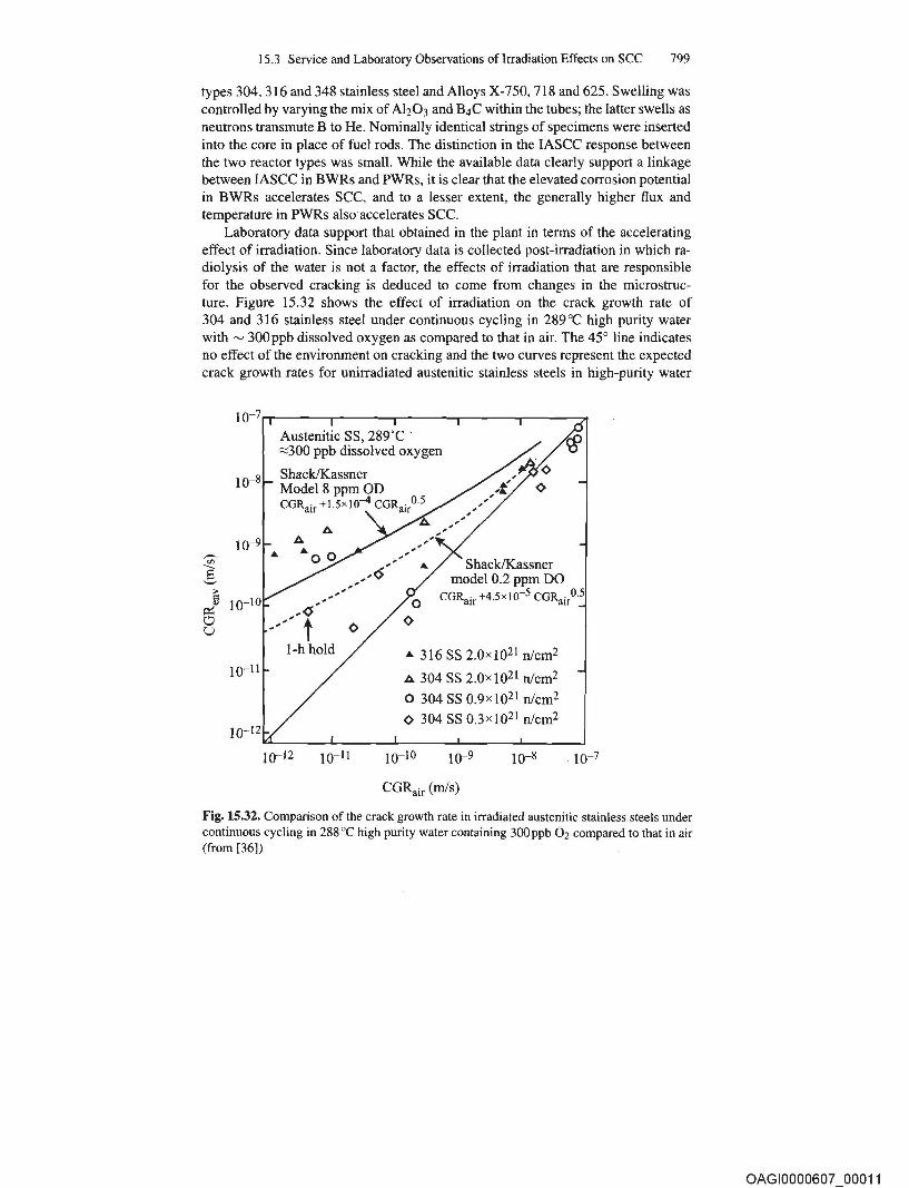
Laboratory data support that obtained in the plant in terms of the accelerating effect of irradiation. Since laboratory data is collected post-irradiation in which radiolysis of the water is not a factor, the effects of irradiation that are responsible for the observed cracking is deduced to come from changes in the microstructure. Figure 15.32 shows the effect of irradiation on the crack growth rate of 304 and 316 stainless steel under continuous cycling in 289"C high purity water with'" 300ppb dissolved oxygen as compared to that in air. The 45° line indicates no effect of the environment on cracking and the two curves represent the expected crack growth rates for unirradiated austenitic stainless steels in high-purity water
Shack/Kassner Model 8 ppm OD COR· +1 5x10⁻⁴ COR. O.S air . arr
Shack/Kassner model 0.2 ppm DO
COR . +4 5x10-S COR. 0.5 "1m . ·'alr
.... 316 SS 2.0x10²¹ nlcm2
.b.. 304 SS 2.0x 10²¹ nlcm2
o 304 SS 0.9x l021 nlcm2
¢ 304 SS 0.3x10²¹ nlcm2
~ ______ ~ ____ ~ ______ ~ ______ L-____ ~
10-12 10-11 10-10 10-9 10-8 10-7
CGRair (rn/s)
Fig. 15.32. Comparison of the crack growth rate in irradiated austenitic stainless steels under continuous cycling in 288°C high purity water containing 300ppb 02 compared to that in air (from [36])
OAGI0000607 00011
800 15 Environmentally Assisted Cracking of Irradiated Metals and Alloys
with either 8ppm (solid) or 0.2ppm (dashed) dissolved oxygen [36]. By comparing the data at different neutron fluence levels, it is clear that both the environment and the fluence level affect the crack growth rate. The crack growth rate in 304 SS irradiated to 2 x 10²¹ n/ cm2 is over an order of magnitude greater than that for irradiation at 0.3 x 10²¹ n/cm2.
Since the early 1990s, the plant and laboratory evidence of IASee makes a compelling case that cracking is environmentally assisted and that there is a wellbehaved continuum in response over ranges in fluence, corrosion potential, temperature, stress, etc. Since there is a consistent trend toward increasing IASee susceptibility with increasing corrosion potential in BWRs (e.g., Figs. lS.30a and IS.31), PWRs should be less susceptible to IASec. However, other factors distinguish PWRs from BWRs, including their higher temperatures, ~ lOx higher neutron fluence in core structural components, higher hydrogen fugacity, and the borated-lithiated water chemistry (including the possibility of localized boiling and thermal concentration cells in crevices from gamma heating which could lead to aggressive local chemistries). The possible role of radiation-induced segregation of Si may be especially important in accounting for the limited difference in see response at high potential (BWR) vs. low potential (PWR) at high fluence.
The two most widespread examples of irradiation-assisted see are in BWR core shrouds and PWR baffled bolts although susceptibility clearly exists in other areas, such as control blade components, fuel components, the BWR top guide, etc., see in the BWR core shroud occurs almost exclusively near the welds (both circumferential and vertical), and initiation is observed from both the inside (ID) and outside (OD) surfaces (the shroud separates the upward core flow from the downward re-circulation flow that occurs in the annulus between the shroud and the pressure vessel). This large diameter welded "pipe" has inherent susceptibility to see, related primarily to weld residual stresses and weld shrinkage strains, and cracking is observed in both low fluence and moderate fluence areas. Severe surface working has also been found to aggravate IASee in core shrouds. The extent of the enhancement in see susceptibility by irradiation is limited, because while radiation hardening and radiation-induced segregation occur, radiation creep relaxes the weld residuals stress.
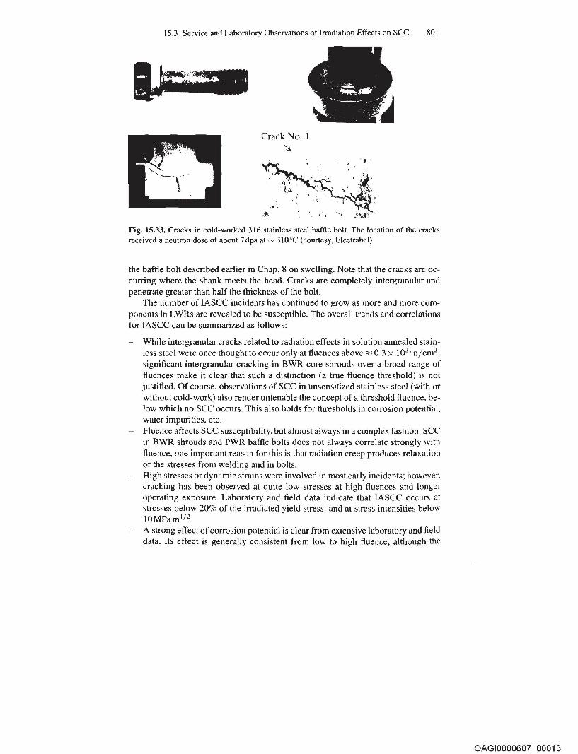
Extensive failures of PWR baffle bolts have occurred beginning in the 1990s [34, 3S] although large plant-to-plant and heat-to-heat differences are observed. Most baffle bolts are fabricated from type 316 stainless steel cold-worked to ~ IS% to increase their yield strength. The complex baffle former structure exists in a PWR because the fuel does not have a surrounding "channel", so the baffle former structure must conform closely to the geometry of the fuel to provide well-distributed water flow. The baffle former plates are usually made from annealed type 304 stainless steel. Because of their proximity to the fuel, very high fluences can develop, up to '" 80dpa by the end of the original design life. The high gamma flux produces significant heating in the components, in some instances estimated at 40 0e above the coolant temperature, especially in designs where the PWR coolant does not have good access to the bolt shank. Figure 15.33 shows micrographs of IG cracking in
OAGl0000607 00012
15.3 Service and Laboratory Observations of Irradiation Effects on SCC 801
Crack No. I ~
Fig. 15.33. Cracks in cold-worked 316 stainless steel baffle bolt. The location of the cracks received a neutron dose of about 7 dpa at ~ 310°C (courtesy, Electrabel)
the baffle bolt described earlier in Chap. 8 on swelling. Note that the cracks are occurring where the shank meets the head. Cracks are completely intergranular and penetrate greater than half the thickness of the bolt.
The number of IASCC incidents has continued to grow as more and more components in LWRs are revealed to be susceptible. The overall trends and correlations for IASCC can be summarized as follows:
- While intergranular cracks related to radiation effects in solution annealed stainless steel were once thought to occur only at fluences above::::; 0.3 x 10²¹ n/cm2
,
significant intergranular cracking in BWR core shrouds over a broad range of fluences make it clear thai such a distinction (a true fluence threshold) is not justified. Of course, observations of SCC in unsensitized stainless steel (with or without cold-work) also render untenable the concept of a threshold fluence, below which no see occurs. This also holds for thresholds in corrosion potential, water impurities, etc.
- Fluence affects see susceptibility, but almost always in a complex fashion. see in BWR shrouds and PWR baffle bolts does not always correlate strongly with fluence, one important reason for this is that radiation creep produces relaxation of the stresses from welding and in bolts.
- High stresses or dynamic strains were involved in most early incidents; however. cracking has been observed at quite low stresses at high fluences and longer operating exposure. Laboratory and field data indicate that IASee occurs at stresses below 20% of the irradiated yield stress, and at stress intensities below IOMPam l / 2.
A strong effect of corrosion potential is clear from extensive laboratory and field data. Its effect is generally consistent from low to high fluence, although the
OAGI0000607 00013
802 15 Environmentally Assisted Cracking of Irradiated Metals and Alloys
quantitative change associated with changes in potential vary. Materials prone to high radiation-induced changes in Si level may exhibit a very limited effect of corrosion potential. A true threshold potential clearly does not exist, as irradiated materials exhibit IASCC in de-aerated water.
- Solution conductivity (i.e., impurities, especially chloride and sulfate) strongly affects cracking propensity in BWR water. This correlation applies equally to low and high flux regions and to stainless steels and nickel-base alloys. Indeed, the correlation closely parallels that from out-of-core.
- Crevice geometries exacerbate cracking due primarily to their ability to create a more aggressive crevice chemistry from the gradient in corrosion potential (in BWRs) or in temperature (most relevant to PWRs).
- Cold-work often exacerbates cracking (esp. abusive surface grinding), although it can also delay the onset of some radiation effects.
- Temperature has an important effect on IASCC, enhancing both crack initiation and growth rate.
- Grain boundary carbides and chromium depletion are not required for susceptibility, although furnace sensitized stainless steels are clearly highly susceptible to cracking in-core. Cr depletion remains a primary CUlprit, although its effect is most pronounced in pH-shifted environments, as can develop when potential or thermal gradients exist. The role of N, S, P, and other grain boundary segregants is less clear.
- The fluence at which IASCC is observed is dependent on applied stress and strain, corrosion potential, solution conductivity, crevice geometry, etc. At sufficiently high conductivities, cracking has been observed in solution annealed stainless steel in the field and in the laboratory. Thus, while convenient in a practical engineering sense, the concept of a "threshold" fluence (or stress, corrosion potential, etc.) is scientifically misleading as cracking susceptibility and morphology are properly considered an interdependent continuum over many relevant parameters.
The field and laboratory data available in the early 1980s, coupled with broader fundamental understanding of environmental cracking in hot water, led to the hypothesis that among innumerable possible radiation effects the most significant factors were radiation-induced segregation at grain boundaries, radiation hardening (elevation of the yield strength), deformation mode, radiation creep relaxation (of constant displacement stresses, e.g., in welds and bolts), and radiolysis (elevated corrosion potential in BWRs). Other factors could also be important in some instances, such as void formation, which may also affect fracture toughness, and can produce differential swelling that causes re-Ioading of components like baffle bolts.
15.3.2 Ferritic Alloys
Ferritic alloys are also susceptible to environmentally enhanced cracking in hightemperature water. The role of irradiation alone on the fatigue crack growth rate in pressure vessel steels was discussed in Chap. 13, where it was determined that
OAGI0000607 00014
...... b 40 -x
15.3 Service and Laboratory Observations of Irradiation Effects on see 803
~ PWR Environment
DArgon
Spectrum Spectrum (3Hz) 03 H
Mrms= 40 MPafril· z
Peaks (3Hz)
Trapezoida1s (3Hz) AKrms= 15.5 MPafril
AKrms= 33 MPafril ~
~ 30 Rip~les (3Hz) - ~ ..c:: Mrms- 6.0 MPafril U l NNNNNNHNM 01) 20
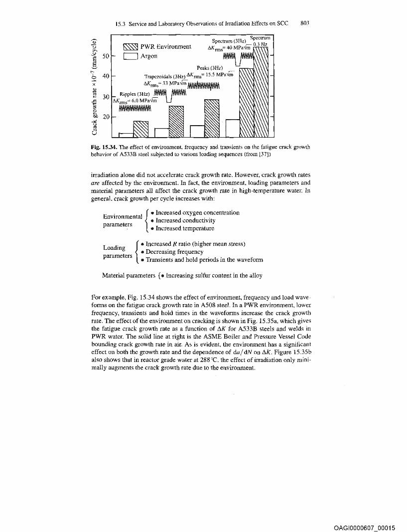
Fig. 15.34. The effect of environment, frequency and transients on the fatigue crack growth behavior of A533B steel subjected to various loading sequences (from [37])
irradiation alone did not accelerate crack growth rate. However, crack growth rates are affected by the environment. In fact, the environment, loading parameters and material parameters all affect the crack growth rate in high-temperature water. In general, crack growth per cycle increases with:
E . I { • Increased oxygen concentration nVIronmenta . . • Increased conductIvIty
parameters • Increased temperature
L d· { • Increased R ratio (higher mean stress) oa mg . • Decreasmg frequency
parameters T· d h ld . d· h f • ranSlents an 0 peno s In t e wave orm
Material parameters {. Increasing sulfur content in the alloy
For example, Fig. 15.34 shows the effect of environment, frequency and load waveforms on the fatigue crack growth rate in A508 steel. In a PWR environment, lower frequency, transients and hold times in the waveforms increase the crack growth rate. The effect of the environment on cracking is shown in Fig. 15.35a, which gives the fatigue crack growth rate as a function of ilK for A533B steels and welds in PWR water. The solid line at right is the ASME Boiler and Pressure Vessel Code bounding crack growth rate in air. As is evident, the environment has a significant effect on both the growth rate and the dependence of daj dN on ilK. Figure 15.35b also shows that in reactor grade water at 288°C, the effect of irradiation only minimally augments the crack growth rate due to the environment.
OAGI0000607 00015
~il,~,~.,\wi' Fu8l~me(l'taJs of ~~cfiation Mate'!¥$:$(ien~e
, Metat~!a'm~ AI I O¥$ , ' .
"
R:adiation Materials Science ot the: effects of radhttibnOll. particle~.~trike·aso~i4)'U;'i'~, " ,.L.L".LOU;Sm~QC;:~~~leS,0(p~3Ur:, the physical andme~ha,ical pr()p~ftf~~~ alloys represent an important their use\in nuclear reactor cores, are subject to fields. Radiation causes metals and alloys to swell, distort, harden, soften and deform. This textbook a,n~ re.tfren~~,sqvers"
:;e:~:: :!~,:~:~a:;:i~t:~~~~:f ~:e ~e1t!:g~a'd~rt' damage, the physical effects of irradiation and the changes i~!';' mechanical behavior of irtadi-ated"met~ and a1Jot.~ ~~G' !.;~r.\ are developed systematically and quantitatively, supported.:llriiii"{i" examples, references for further reading and problems at th~'" end of each chapter. Beyond addressing students enrolling for a " materials sciences or nuclear engineering degree, the book wiJ.Ir: benefit professionals in laboratories, reactor manufacturers and:, specialists working in the utility industry.