Page 1
USPAS Accelerator Physics June 2013USPAS Accelerator Physics 2016USPAS Accelerator Physics 2016
Fundamentals of RF Cavities
Suba De Silva, S. A. Bogacz, G. A. Krafft,
and R. Gamage
Old Dominion University / Jefferson Lab
Colorado State University
Lecture 10
USPAS – June, 2016
Page 2
USPAS Accelerator Physics June 2013USPAS Accelerator Physics 2016
• RF Cavities
– Cavity Basics
– RF Properties
– TM Type Cavities
• Types of Cavities
– Accelerating Cavities
– Low β cavities
– Deflecting/Crabbing Cavities
• Limitations in SRF Cavities
• Losses in RF Cavities
Outline
Page 3
USPAS Accelerator Physics June 2013USPAS Accelerator Physics 2016
• H. Padamsee, J. Knobloch, T. Hays “ RF Superconductivity
for Accelerators”, John Wiley & Sons, Inc; ISBN 0-471-
15432-6
• Proceedings of the Workshops on RF Superconductivity
1981–2015 – (ww.jacow.org)
• CERN Accelerator School – 1955 – 2016
(https://cds.cern.ch/collection/CERN%20Yellow%20Report
s?ln=en)
Suggested Literature
Page 4
USPAS Accelerator Physics June 2013USPAS Accelerator Physics 2016
RF Cavities
RF cavities made of different materials, in different shapes and sizes
1500 MHz 5-cell
1300 MHz 9-cellQuarter
Wave
Cavity
Half
Wave
Cavity
Triple
Spoke
Cavity
Single
Spoke
Cavity
CESR 500
MHz Cavity
(Cornell) LEP 350 MHz 4-cell Nb on Cu
Page 5
USPAS Accelerator Physics June 2013USPAS Accelerator Physics 2016
• Space enclosed by conducting walls that can sustain an
infinite number of resonant electromagnetic modes
• Shape is selected so that a particular mode can efficiently
transfer its energy to a charged particle
• An isolated mode can be modeled by an LRC circuit
• Lorentz force
• An accelerating cavity needs to provide an electric field
(E) longitudinal with the velocity of the particle
• Magnetic fields (H) provide deflection but no acceleration
RF Cavities
Page 6
USPAS Accelerator Physics June 2013USPAS Accelerator Physics 2016
• Simplest form of RF resonator LC circuit
• LC circuit Pill box cavity
– Electric field is concentrated near axis
– Magnetic field is concentrated at outer cylindrical wall
RF Resonator
Page 7
USPAS Accelerator Physics June 2013USPAS Accelerator Physics 2016
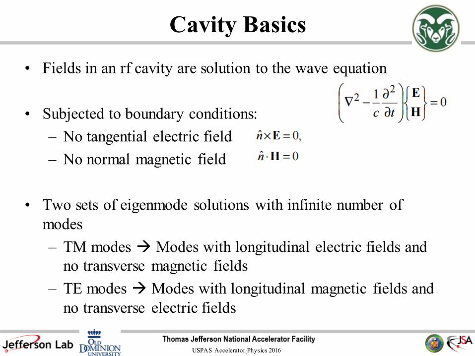
• Fields in an rf cavity are solution to the wave equation
• Subjected to boundary conditions:
– No tangential electric field
– No normal magnetic field
• Two sets of eigenmode solutions with infinite number of
modes
– TM modes Modes with longitudinal electric fields and
no transverse magnetic fields
– TE modes Modes with longitudinal magnetic fields and
no transverse electric fields
Cavity Basics
Page 8
USPAS Accelerator Physics June 2013USPAS Accelerator Physics 2016
TM and TE Modes in a Pill Box Cavity
xmn is the nth root of Jm
x’mn is the nth root of J’m
Page 9
USPAS Accelerator Physics June 2013USPAS Accelerator Physics 2016
• TM010
– Electric field is purely longitudinal
– Electric and magnetic fields have no angular dependence
– Frequency depends only on radius, independent on length
• TM0np
– Monopole modes that can couple to the beam and exchange energy
• TM1np
– Dipole modes that can deflect the beam
• TE modes
– No longitudinal E field
– Cannot couple to the beam
– TE-type modes can deflect the beam
Modes in Pill Box Cavity
Page 10
USPAS Accelerator Physics June 2013USPAS Accelerator Physics 2016
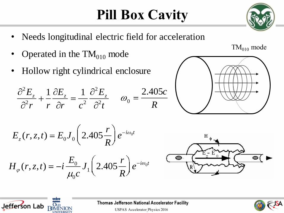
Pill Box Cavity
• Needs longitudinal electric field for acceleration
• Operated in the TM010 mode
• Hollow right cylindrical enclosure
2 2
2 2 2
1 1z z zE E E
r r r c t0
2.405c
R
0
0 0( , , ) 2.405i t
z
rE r z t E J e
R
001
0
( , , ) 2.405i tE r
H r z t i J ec R
E
TM010 mode
Page 11
USPAS Accelerator Physics June 2013USPAS Accelerator Physics 2016
TM010 Mode in a Pill Box Cavity
0 0 01
0 1 01
01
01 01
01
0
0
2.405
0.3832
r z
r z
rE E E E J x
R
R rH H H i E J x
x R
cx x
R
xR
E
TM010 mode
R
• Frequency scales inversely with cavity radius
Page 12
USPAS Accelerator Physics June 2013USPAS Accelerator Physics 2016
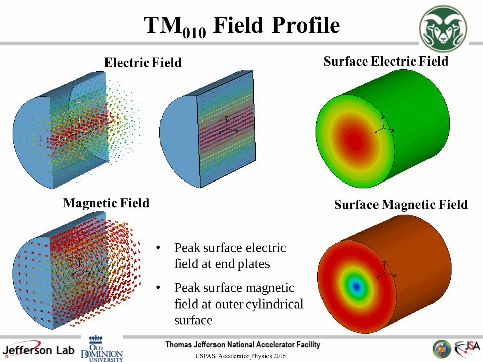
TM010 Field Profile
Magnetic Field
Electric Field Surface Electric Field
Surface Magnetic Field
• Peak surface electric
field at end plates
• Peak surface magnetic
field at outer cylindrical
surface
Page 13
USPAS Accelerator Physics June 2013USPAS Accelerator Physics 2016USPAS Accelerator Physics 2016
Cavity RF Properties
Page 14
USPAS Accelerator Physics June 2013USPAS Accelerator Physics 2016
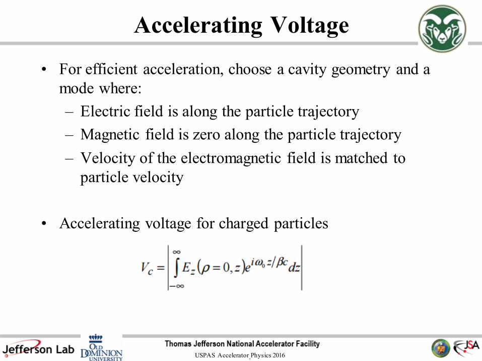
• For efficient acceleration, choose a cavity geometry and a
mode where:
– Electric field is along the particle trajectory
– Magnetic field is zero along the particle trajectory
– Velocity of the electromagnetic field is matched to
particle velocity
• Accelerating voltage for charged particles
Accelerating Voltage
Page 15
USPAS Accelerator Physics June 2013USPAS Accelerator Physics 2016
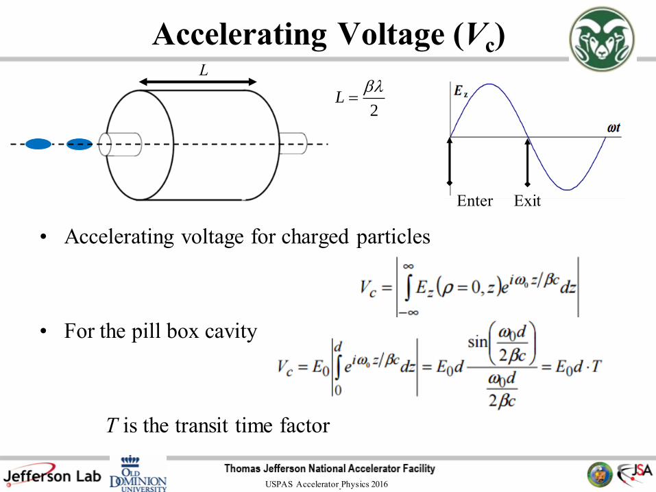
• Accelerating voltage for charged particles
• For the pill box cavity
T is the transit time factor
Accelerating Voltage (Vc)L
Enter Exit
2L
Page 16
USPAS Accelerator Physics June 2013USPAS Accelerator Physics 2016
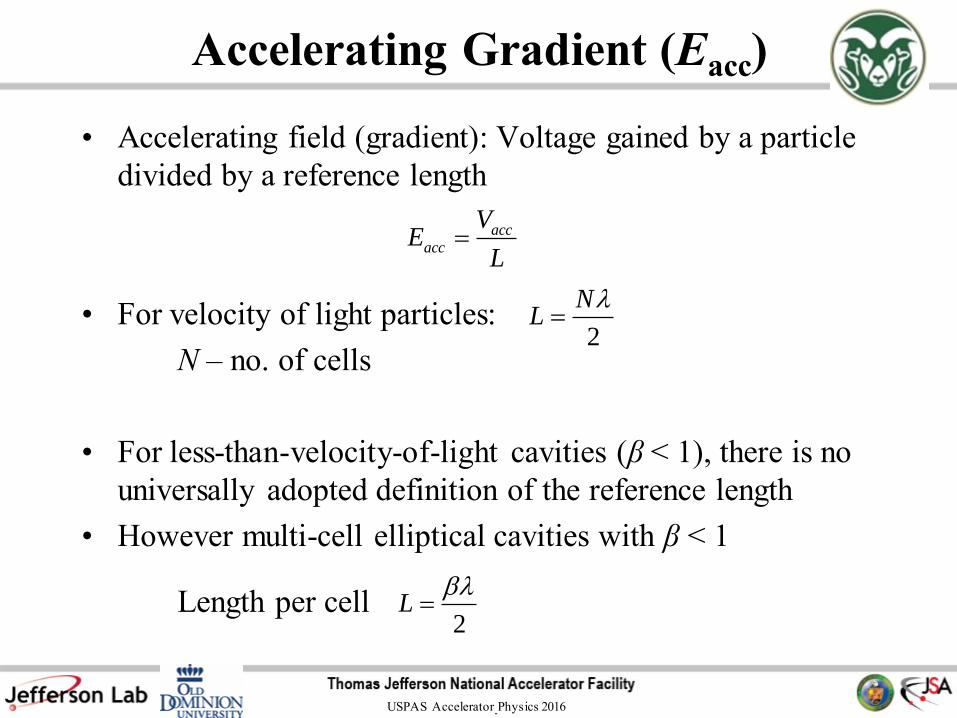
• Accelerating field (gradient): Voltage gained by a particle
divided by a reference length
• For velocity of light particles:
N – no. of cells
• For less-than-velocity-of-light cavities (β < 1), there is no
universally adopted definition of the reference length
• However multi-cell elliptical cavities with β < 1
Length per cell
Accelerating Gradient (Eacc)
2
NL
acc
acc
VE
L
2L
Page 17
USPAS Accelerator Physics June 2013USPAS Accelerator Physics 2016
• Energy density in electromagnetic field:
• Because of the sinusoidal time dependence and the 90º
phase shift, the energy oscillates back and forth between
the electric and magnetic field
• Total energy content in the cavity:
Stored Energy (U)
Page 18
USPAS Accelerator Physics June 2013USPAS Accelerator Physics 2016
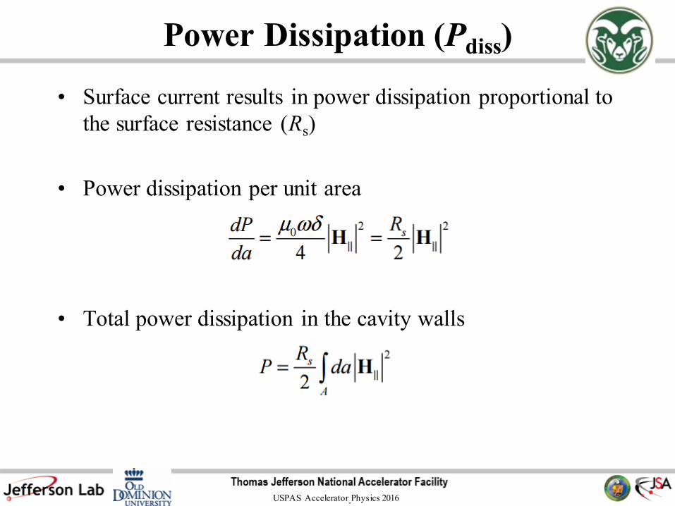
• Surface current results in power dissipation proportional to
the surface resistance (Rs)
• Power dissipation per unit area
• Total power dissipation in the cavity walls
Power Dissipation (Pdiss)
Page 19
USPAS Accelerator Physics June 2013USPAS Accelerator Physics 2016
• For normal conductors
– per unit length
– per unit area
• For superconductors
– per unit length
– per unit area
Power Dissipation (Pdiss)
Page 20
USPAS Accelerator Physics June 2013USPAS Accelerator Physics 2016
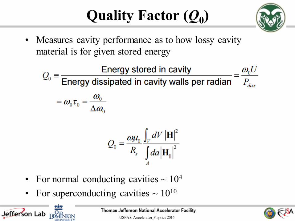
Quality Factor (Q0)
• Measures cavity performance as to how lossy cavity
material is for given stored energy
• For normal conducting cavities ~ 104
• For superconducting cavities ~ 1010
Page 21
USPAS Accelerator Physics June 2013USPAS Accelerator Physics 2016
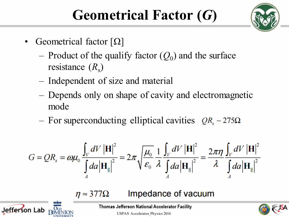
• Geometrical factor [Ω]
– Product of the qualify factor (Q0) and the surface
resistance (Rs)
– Independent of size and material
– Depends only on shape of cavity and electromagnetic
mode
– For superconducting elliptical cavities
Geometrical Factor (G)
Page 22
USPAS Accelerator Physics June 2013USPAS Accelerator Physics 2016
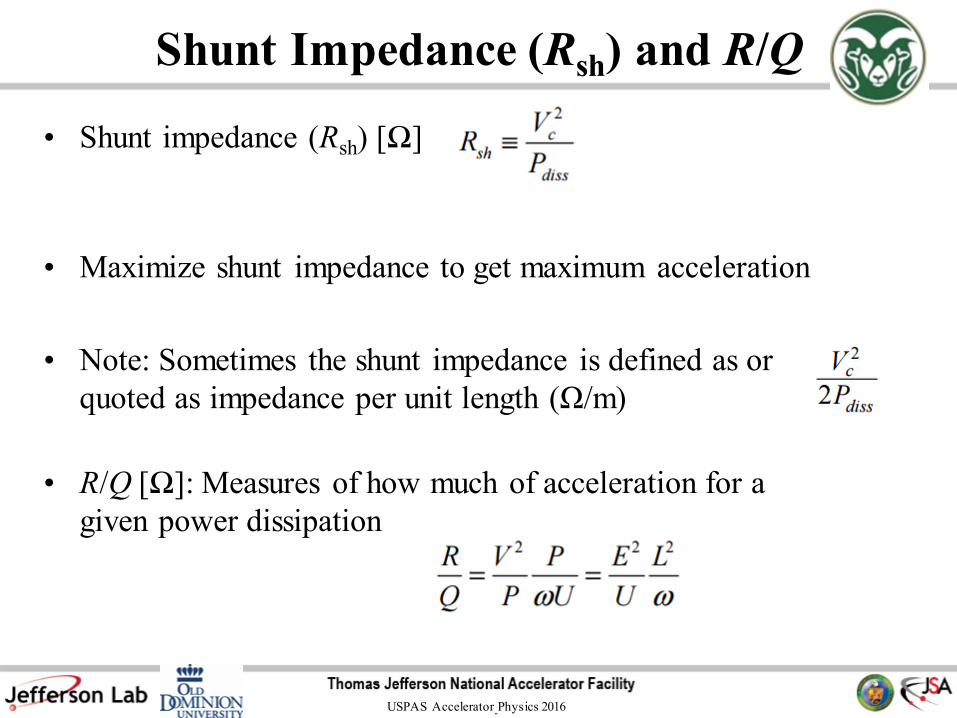
• Shunt impedance (Rsh) [Ω]
• Maximize shunt impedance to get maximum acceleration
• Note: Sometimes the shunt impedance is defined as or
quoted as impedance per unit length (Ω/m)
• R/Q [Ω]: Measures of how much of acceleration for a
given power dissipation
Shunt Impedance (Rsh) and R/Q
Page 23
USPAS Accelerator Physics June 2013USPAS Accelerator Physics 2016
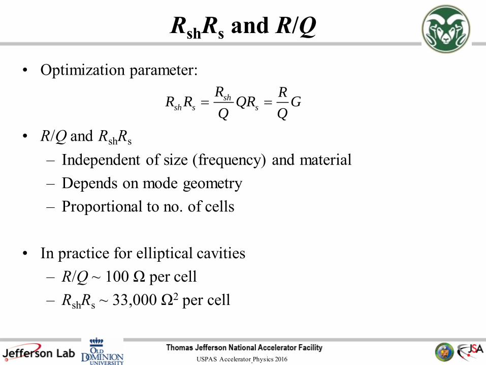
• Optimization parameter:
• R/Q and RshRs
– Independent of size (frequency) and material
– Depends on mode geometry
– Proportional to no. of cells
• In practice for elliptical cavities
– R/Q ~ 100 Ω per cell
– RshRs ~ 33,000 Ω2 per cell
RshRs and R/Q
sh
sh s s
R RR R QR G
Q Q
Page 24
USPAS Accelerator Physics June 2013USPAS Accelerator Physics 2016
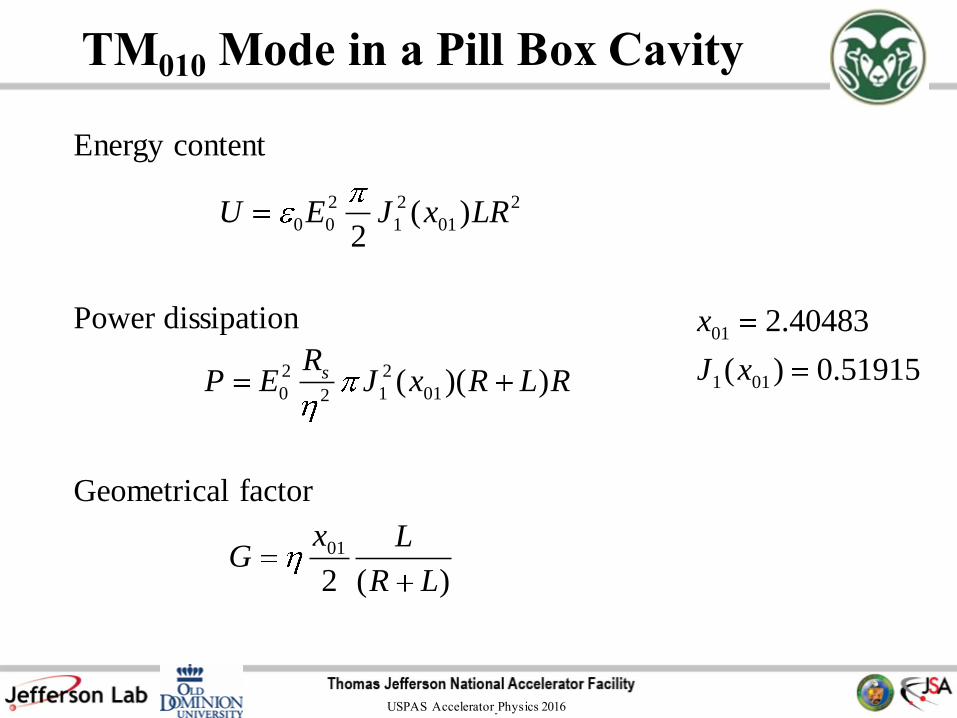
TM010 Mode in a Pill Box Cavity
Energy content
Power dissipation
Geometrical factor
2 2 2
0 0 1 01( )2
U E J x LR
2 2
0 1 012( )( )sR
P E J x R L R
01
2 ( )
x LG
R L
01
1 01
2.40483
( ) 0.51915
x
J x
Page 25
USPAS Accelerator Physics June 2013USPAS Accelerator Physics 2016
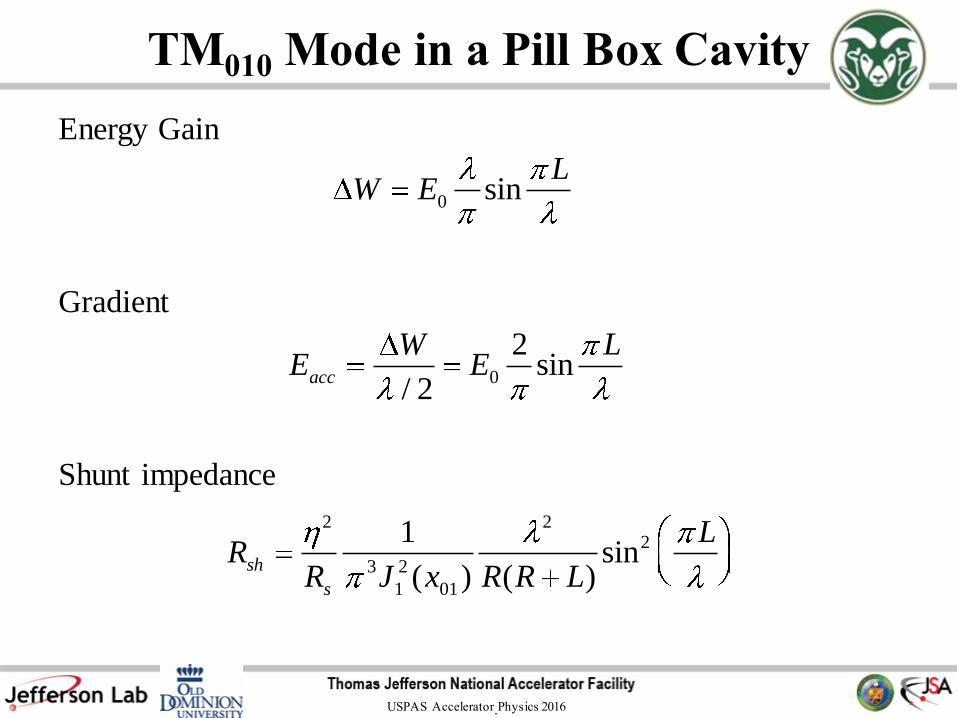
TM010 Mode in a Pill Box Cavity
Energy Gain
Gradient
Shunt impedance
0 sinL
W E
2 22
3 2
1 01
1sin
( ) ( )sh
s
LR
R J x R R L
0
2sin
/ 2acc
W LE E
Page 26
USPAS Accelerator Physics June 2013USPAS Accelerator Physics 2016USPAS Accelerator Physics 2016
Accelerating Cavities
Page 27
USPAS Accelerator Physics June 2013USPAS Accelerator Physics 2016
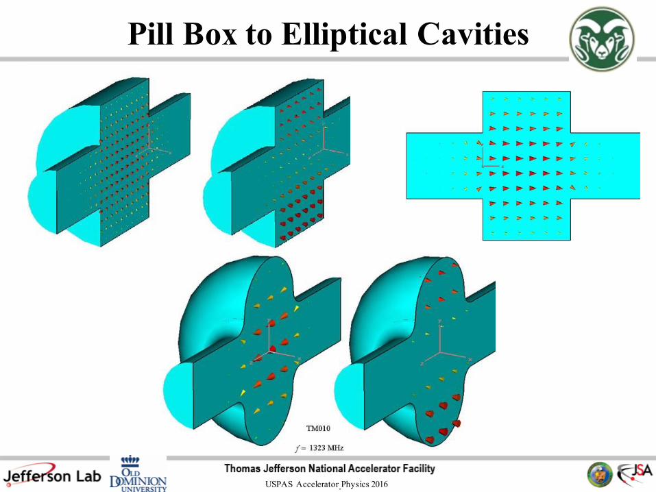
• Beam tubes reduce the electric field on axis
– Gradient decreases
– Peak fields increase
– R/Q decreases
Real Cavities
Page 28
USPAS Accelerator Physics June 2013USPAS Accelerator Physics 2016
Pill Box to Elliptical Cavities
Page 29
USPAS Accelerator Physics June 2013USPAS Accelerator Physics 2016
Single Cell Cavities
Electric field high at iris
Magnetic field high at equator
• Important parameters: Ep/Eacc and Bp/Eacc
• Must minimize the ratios as smaller as possible
Page 30
USPAS Accelerator Physics June 2013USPAS Accelerator Physics 2016
Single Cell Cavities
270 Ω
88 Ω/cell
2.5
52 Oe/MV/m
Cornell SC 500 MHz
Page 31
USPAS Accelerator Physics June 2013USPAS Accelerator Physics 2016
• What is the purpose of the cavity?
• What EM parameters should be optimized to meet the
design specs?
• Beam aperture
• Peak surface field ratios – Ep/Eacc, Bp/Eacc
• Shunt impedance – RshRs
• Higher Order Mode (HOM) extraction
Cell Shape Design
The “perfect” shape does not exist, it all
depends on your application
Page 32
USPAS Accelerator Physics June 2013USPAS Accelerator Physics 2016
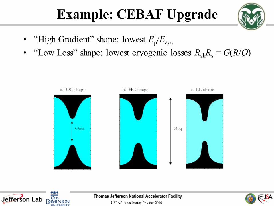
• “High Gradient” shape: lowest Ep/Eacc
• “Low Loss” shape: lowest cryogenic losses RshRs = G(R/Q)
Example: CEBAF Upgrade
Page 33
USPAS Accelerator Physics June 2013USPAS Accelerator Physics 2016
• The field emission is not a hard limit in the performance of
sc cavities if the surface preparation is done in the right way
• Unlikely this, magnetic flux on the wall limits performance
of a sc cavity (Q0 decreases or/and quench). Hard limit ~180
mT for Nb
TM-Cavity Design
Bpeak / Eacc should be low
1. Cavities may operate at
higher gradients.
2. Cavities may operate at
lower cryogenic load.
2 ( / )
diss s
acc
P R
V G R Q
Page 34
USPAS Accelerator Physics June 2013USPAS Accelerator Physics 2016
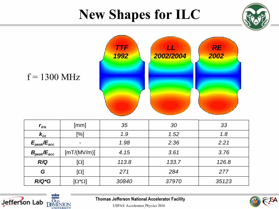
New Shapes for ILC
30840[Ω*Ω]R/Q*G
271[Ω]G
113.8[Ω]R/Q
4.15[mT/(MV/m)]Bpeak/Eacc
1.98-Epeak/Eacc
1.9[%]kcc
35[mm]riris
37970
284
133.7
3.61
2.36
1.52
30
35123
277
126.8
3.76
2.21
1.8
33
TTF LL RE
1992 2002/2004 2002
f = 1300 MHz
Page 35
USPAS Accelerator Physics June 2013USPAS Accelerator Physics 2016
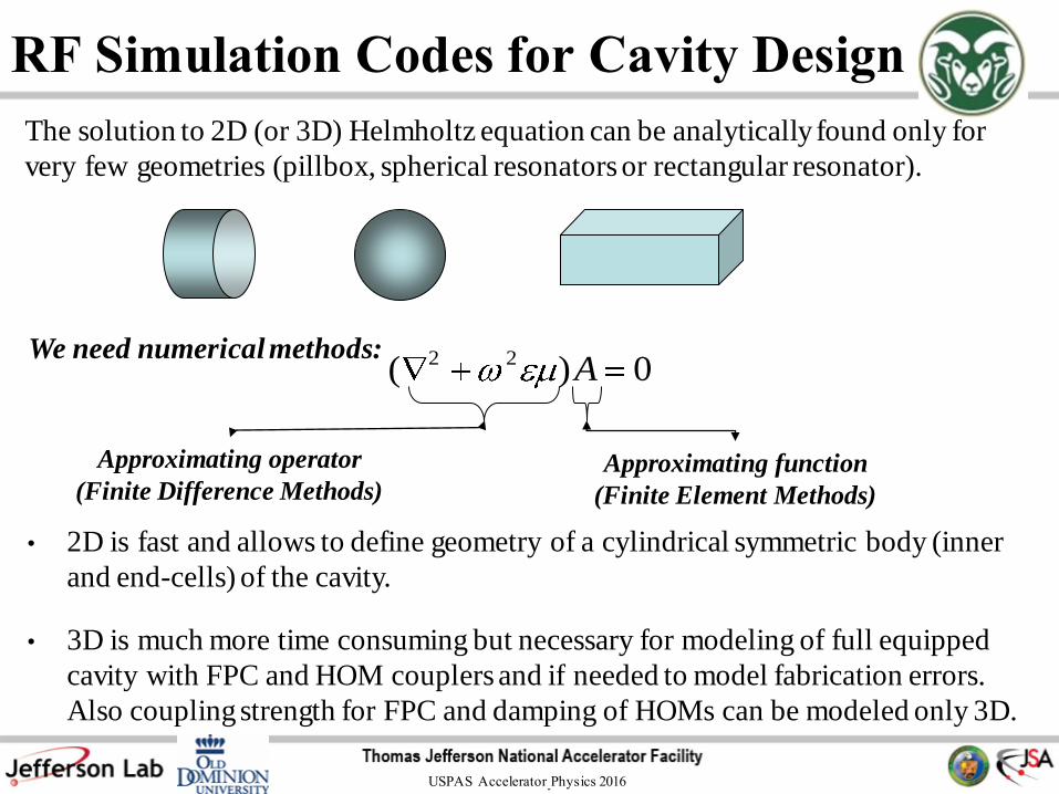
RF Simulation Codes for Cavity Design
• 2D is fast and allows to define geometry of a cylindrical symmetric body (inner
and end-cells) of the cavity.
• 3D is much more time consuming but necessary for modeling of full equipped
cavity with FPC and HOM couplers and if needed to model fabrication errors.
Also coupling strength for FPC and damping of HOMs can be modeled only 3D.
2 2( ) 0A
The solution to 2D (or 3D) Helmholtz equation can be analytically found only for
very few geometries (pillbox, spherical resonators or rectangular resonator).
We need numerical methods:
Approximating operator
(Finite Difference Methods)Approximating function
(Finite Element Methods)
Page 36
USPAS Accelerator Physics June 2013USPAS Accelerator Physics 2016
• Free, 2D finite-difference code to design cylindrically
symmetric structures (monopole modes only)
• Use symmetry planes to reduce number of mesh points
SUPERFISH
File di SuperFish Generato da BuildCav F = 1472.6276 MHz
C:\LANLV7\HALFCEBSC.AF 11-27-2006 16:58:22
0
1
2
3
4
5
6
7
8
9
10
11
12
0
1
2
3
4
5
6
7
8
9
10
11
12
0 2 4 6 8 10 12 14 16
File di SuperFish Generato da BuildCav F = 1472.6276 MHz
C:\LANLV7\HALFCEBSC.AF 11-27-2006 16:58:22
7.30
7.40
7.50
7.60
7.70
7.80
7.90
8.00
8.10
7.30
7.40
7.50
7.60
7.70
7.80
7.90
8.00
8.10
2 2.1 2.2 2.3 2.4 2.5 2.6 2.7 2.8 2.9 3 3.1 3.2
http://laacg1.lanl.gov/laacg/serv
ices/download_sf.phtml
Page 37
USPAS Accelerator Physics June 2013USPAS Accelerator Physics 2016
• Expensive, 3D finite-element code, used to design complex
RF structure
• Runs on PC
• Perfect boundary approximation
http://www.cst.com/Content/Products/MWS/Overview.aspx
CST Microwave Studio
Hexahedral mesh
Page 38
USPAS Accelerator Physics June 2013USPAS Accelerator Physics 2016
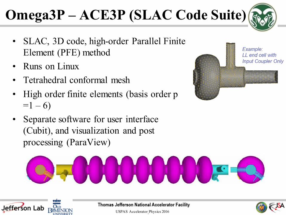
• SLAC, 3D code, high-order Parallel Finite
Element (PFE) method
• Runs on Linux
• Tetrahedral conformal mesh
• High order finite elements (basis order p
=1 – 6)
• Separate software for user interface
(Cubit), and visualization and post
processing (ParaView)
Omega3P – ACE3P (SLAC Code Suite)
Page 39
USPAS Accelerator Physics June 2013USPAS Accelerator Physics 2016
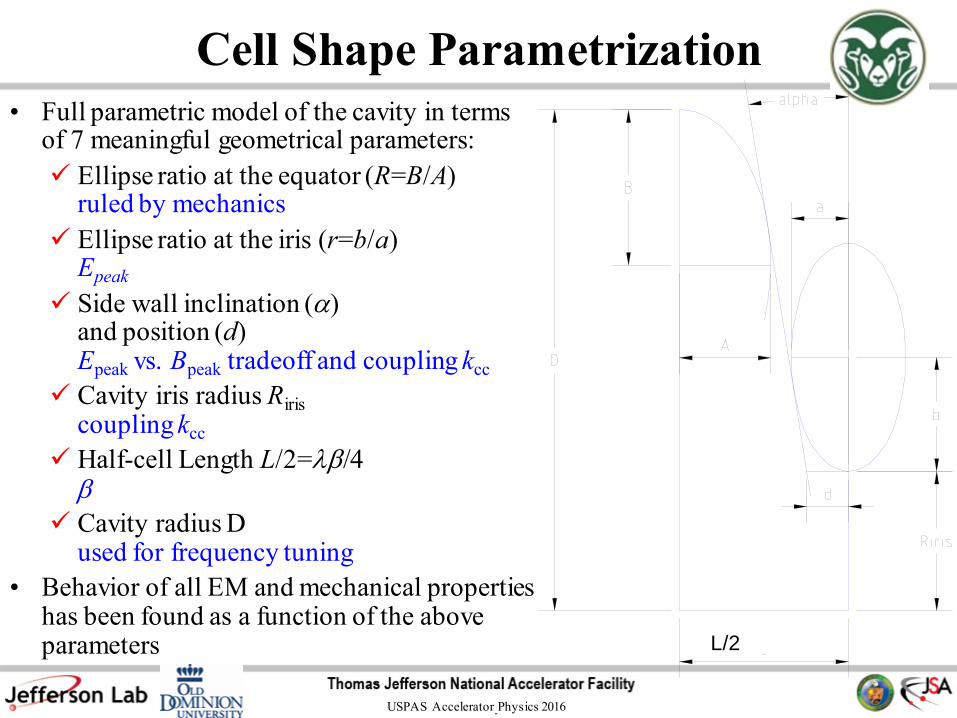
Cell Shape Parametrization
• Full parametric model of the cavity in terms of 7 meaningful geometrical parameters:
Ellipse ratio at the equator (R=B/A)ruled by mechanics
Ellipse ratio at the iris (r=b/a)Epeak
Side wall inclination (a) and position (d)Epeak vs. Bpeak tradeoff and coupling kcc
Cavity iris radius Riris
coupling kcc
Half-cell Length L/2=/4
Cavity radius Dused for frequency tuning
• Behavior of all EM and mechanical properties has been found as a function of the above parameters L/2
Page 40
USPAS Accelerator Physics June 2013USPAS Accelerator Physics 2016
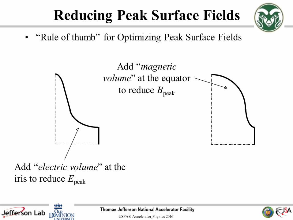
• “Rule of thumb” for Optimizing Peak Surface Fields
Reducing Peak Surface Fields
Add “electric volume” at the
iris to reduce Epeak
Add “magnetic
volume” at the equator
to reduce Bpeak
Page 41
USPAS Accelerator Physics June 2013USPAS Accelerator Physics 2016
Multi-Cell Cavities
Single-cell is attractive from the RF-point of
view:
• Easier to manage HOM damping
• No field flatness problem
• Input coupler transfers less power
• Easy for cleaning and preparation
• But it is expensive to base even a small
linear accelerator on the single cell. We do
it only for very high beam current
machines.
A multi-cell structure is less expensive and offers
higher real-estate gradient but:
• Field flatness (stored energy) in cells
becomes sensitive to frequency errors of
individual cells
• Other problems arise: HOM trapping…
Page 42
USPAS Accelerator Physics June 2013USPAS Accelerator Physics 2016
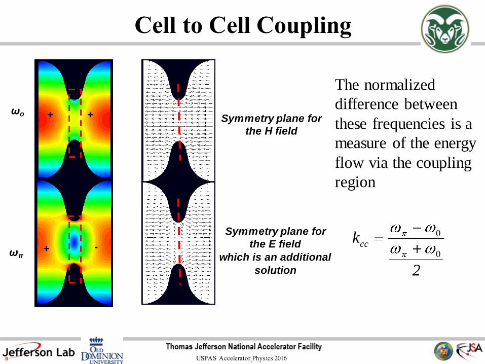
Cell to Cell Coupling
+ +
+ -
Symmetry plane for
the H field
Symmetry plane for
the E field
which is an additional
solution
ωo
ωπ
0
0cck
2
The normalized
difference between
these frequencies is a
measure of the energy
flow via the coupling
region
Page 43
USPAS Accelerator Physics June 2013USPAS Accelerator Physics 2016
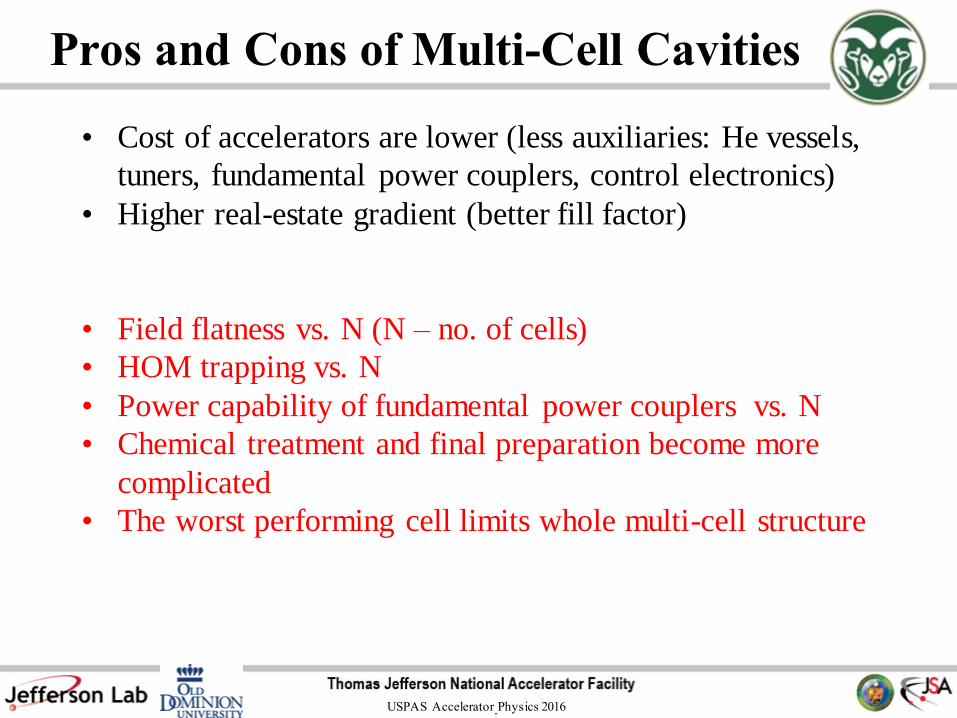
• Cost of accelerators are lower (less auxiliaries: He vessels,
tuners, fundamental power couplers, control electronics)
• Higher real-estate gradient (better fill factor)
• Field flatness vs. N (N – no. of cells)
• HOM trapping vs. N
• Power capability of fundamental power couplers vs. N
• Chemical treatment and final preparation become more
complicated
• The worst performing cell limits whole multi-cell structure
Pros and Cons of Multi-Cell Cavities
Page 44
USPAS Accelerator Physics June 2013USPAS Accelerator Physics 2016
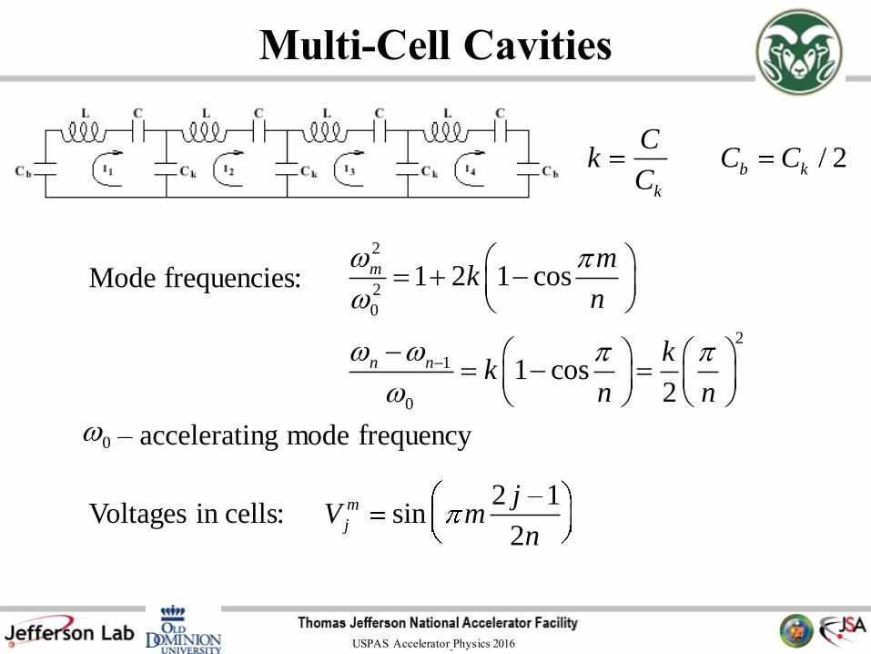
Multi-Cell Cavities
Mode frequencies:
– accelerating mode frequency
Voltages in cells:
2
2
0
2
1
0
1 2 1 cos
1 cos2
m
n n
mk
n
kk
n n
2 1sin
2
m
j
jV m
n
/ 2b k
k
Ck C C
C
0
Page 45
USPAS Accelerator Physics June 2013USPAS Accelerator Physics 2016
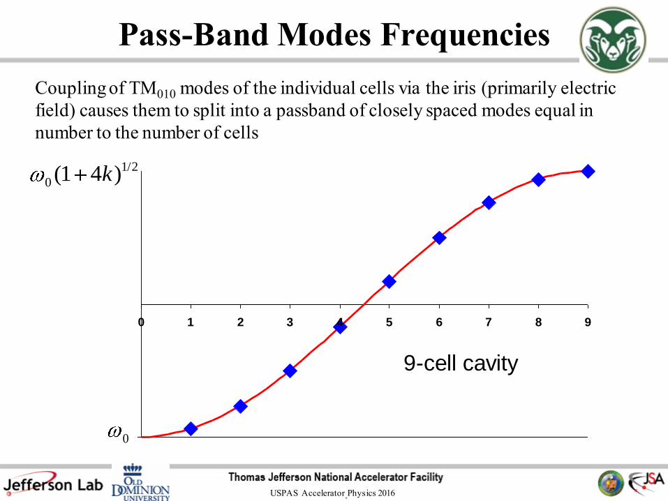
Coupling of TM010 modes of the individual cells via the iris (primarily electric
field) causes them to split into a passband of closely spaced modes equal in
number to the number of cells
Pass-Band Modes Frequencies
-1
0 1 2 3 4 5 6 7 8 9
9-cell cavity
0
1/2
0 (1 4 )k
Page 46
USPAS Accelerator Physics June 2013USPAS Accelerator Physics 2016
Cell Excitations in Pass-Band Modes9 Cell, Mode 1
-1
-0.8
-0.6
-0.4
-0.2
0
0.2
0.4
0.6
0.8
1
1 2 3 4 5 6 7 8 9
9 Cell, Mode 2
-1
-0.8
-0.6
-0.4
-0.2
0
0.2
0.4
0.6
0.8
1
1 2 3 4 5 6 7 8 9
9 Cell, Mode 3
-1
-0.8
-0.6
-0.4
-0.2
0
0.2
0.4
0.6
0.8
1
1 2 3 4 5 6 7 8 9
9 Cell, Mode 4
-1
-0.8
-0.6
-0.4
-0.2
0
0.2
0.4
0.6
0.8
1
1 2 3 4 5 6 7 8 9
9 Cell, Mode 5
-1
-0.8
-0.6
-0.4
-0.2
0
0.2
0.4
0.6
0.8
1
1 2 3 4 5 6 7 8 9
9 Cell, Mode 6
-1
-0.8
-0.6
-0.4
-0.2
0
0.2
0.4
0.6
0.8
1
1 2 3 4 5 6 7 8 9
9 Cell, Mode 7
-1
-0.8
-0.6
-0.4
-0.2
0
0.2
0.4
0.6
0.8
1
1 2 3 4 5 6 7 8 9
9 Cell, Mode 8
-1
-0.8
-0.6
-0.4
-0.2
0
0.2
0.4
0.6
0.8
1
1 2 3 4 5 6 7 8 9
9 Cell, Mode 9
-1
-0.8
-0.6
-0.4
-0.2
0
0.2
0.4
0.6
0.8
1
1 2 3 4 5 6 7 8 9
Page 47
USPAS Accelerator Physics June 2013USPAS Accelerator Physics 2016
• Geometrical differences between cells causes a mixing of
the eigenmodes
• Sensitivity to mechanical deformation depends on mode
spacing
Field Flatness in Multi-Cell Cavities
2
1
0
1 cos2
n n kk
n n
Page 48
USPAS Accelerator Physics June 2013USPAS Accelerator Physics 2016USPAS Accelerator Physics 2016
Low Beta Accelerating Structures –
TEM Class Cavities
Page 49
USPAS Accelerator Physics June 2013USPAS Accelerator Physics 2016
• Two main types of structure geometries
– TEM class (QW, HW, Spoke)
– TM class (Elliptical)
Classification of Structures
Page 50
USPAS Accelerator Physics June 2013USPAS Accelerator Physics 2016
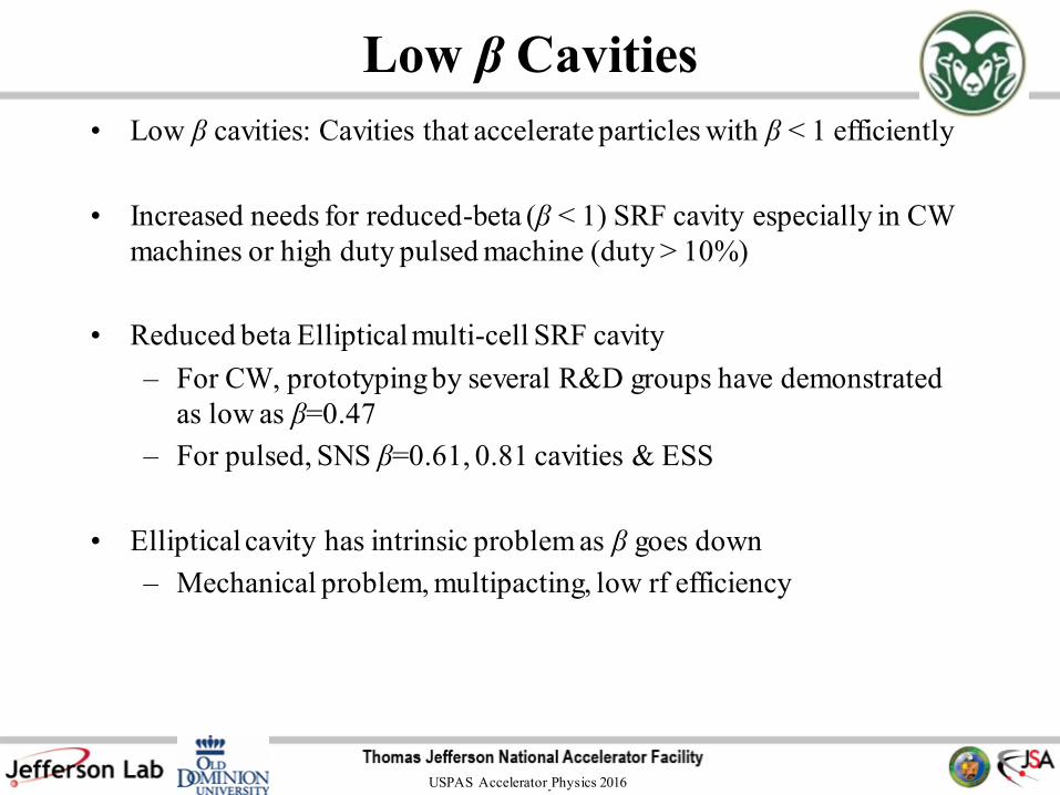
• Low β cavities: Cavities that accelerate particles with β < 1 efficiently
• Increased needs for reduced-beta (β < 1) SRF cavity especially in CW
machines or high duty pulsed machine (duty > 10%)
• Reduced beta Elliptical multi-cell SRF cavity
– For CW, prototyping by several R&D groups have demonstrated
as low as β=0.47
– For pulsed, SNS β=0.61, 0.81 cavities & ESS
• Elliptical cavity has intrinsic problem as β goes down
– Mechanical problem, multipacting, low rf efficiency
Low β Cavities
Page 51
USPAS Accelerator Physics June 2013USPAS Accelerator Physics 2016
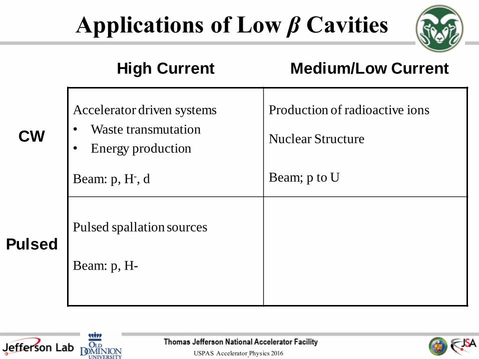
Applications of Low β Cavities
Accelerator driven systems
• Waste transmutation
• Energy production
Beam: p, H-, d
Production of radioactive ions
Nuclear Structure
Beam; p to U
Pulsed spallation sources
Beam: p, H-
High Current Medium/Low Current
CW
Pulsed
Page 52
USPAS Accelerator Physics June 2013USPAS Accelerator Physics 2016
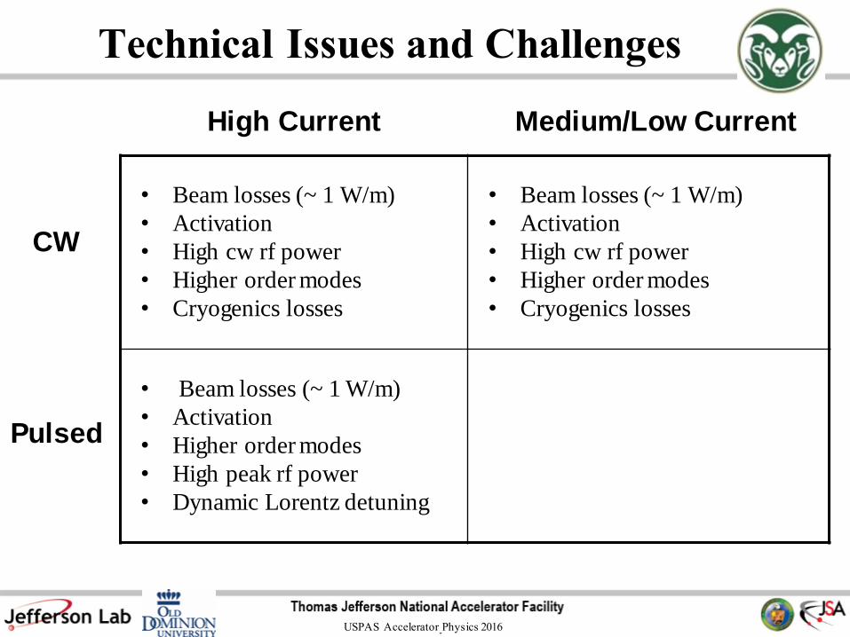
Technical Issues and Challenges
• Beam losses (~ 1 W/m)
• Activation
• High cw rf power
• Higher order modes
• Cryogenics losses
• Beam losses (~ 1 W/m)
• Activation
• High cw rf power
• Higher order modes
• Cryogenics losses
• Beam losses (~ 1 W/m)
• Activation
• Higher order modes
• High peak rf power
• Dynamic Lorentz detuning
High Current Medium/Low Current
CW
Pulsed
Page 53
USPAS Accelerator Physics June 2013USPAS Accelerator Physics 2016
Design Considerations
• Cavities with high acceptance
• Development of high cw
power couplers
• Extraction of HOM power
• Cavities with high shunt
impedance
• Cavities with low sensitivity to vibration
• Development of microphonicscompensation
• Cavities with high shunt impedance• Cavities with large velocity acceptance
(few cells)• Cavities with large beam acceptance
(low frequency, small frequency transitions)
• Cavities with high acceptance
• Development of high peak
power couplers
• Extraction of HOM power
• Development of active
compensation of dynamic
Lorentz detuning
High Current Medium/Low Current
CW
Pulsed
Note:
Large beam acceptance
• Large aperture (transverse acceptance)
• Low frequency (longitudinal acceptance)
Page 54
USPAS Accelerator Physics June 2013USPAS Accelerator Physics 2016
• Resonant transmission lines
– λ/4
Quarter wave
Split ring
Twin quarter wave
Lollipop
– λ/2
Coaxial half wave
Spoke
H-type
• TM type
– Elliptical
– Reentrant
• Other
– Alvarez
– Slotted iris
Basic Geometries
Page 55
USPAS Accelerator Physics June 2013USPAS Accelerator Physics 2016
• Many different shapes and sizes
Low β Cavities
ANL cavities for RIA
Half-wave cavity
RFQ
QW HWSpoke
Page 56
USPAS Accelerator Physics June 2013USPAS Accelerator Physics 2016
• The transit time factor is the ratio of the acceleration voltage to the
(non‐physical) voltage a particle with infinite velocity would see
• Energy gain (W):
• Assuming constant velocity
• Transit time factor:
Transit Time Factor
Page 57
USPAS Accelerator Physics June 2013USPAS Accelerator Physics 2016
• Velocity acceptance
Velocity Acceptance
Velocity Acceptance for Sinusoidal Field Profile
-0.3
-0.2
-0.1
0.0
0.1
0.2
0.3
0.4
0.5
0.6
0.7
0.8
0.9
1.0
0.5 0.6 0.7 0.8 0.9 1.0 1.1 1.2 1.3 1.4 1.5 1.6 1.7 1.8 1.9 2.0g
• Lower the velocity of the
particle or cavity β
o Faster the velocity of the
particle will change
o Narrower the velocity range of
a particular cavity
o Smaller the number of cavities
of that β
o More important: Particle
achieve design velocity
Velocity acceptance for sinusoidal field profile
Page 58
USPAS Accelerator Physics June 2013USPAS Accelerator Physics 2016
Quarter–Wave Resonator
Page 59
USPAS Accelerator Physics June 2013USPAS Accelerator Physics 2016
Quarter–Wave Resonator
The transmission line can be shorter
than λ/4 and still resonate at the right
frequency if it is terminated by the
appropriate loading capacitance Γ.
Capacitively loaded λ/4 transmission line
Page 60
USPAS Accelerator Physics June 2013USPAS Accelerator Physics 2016
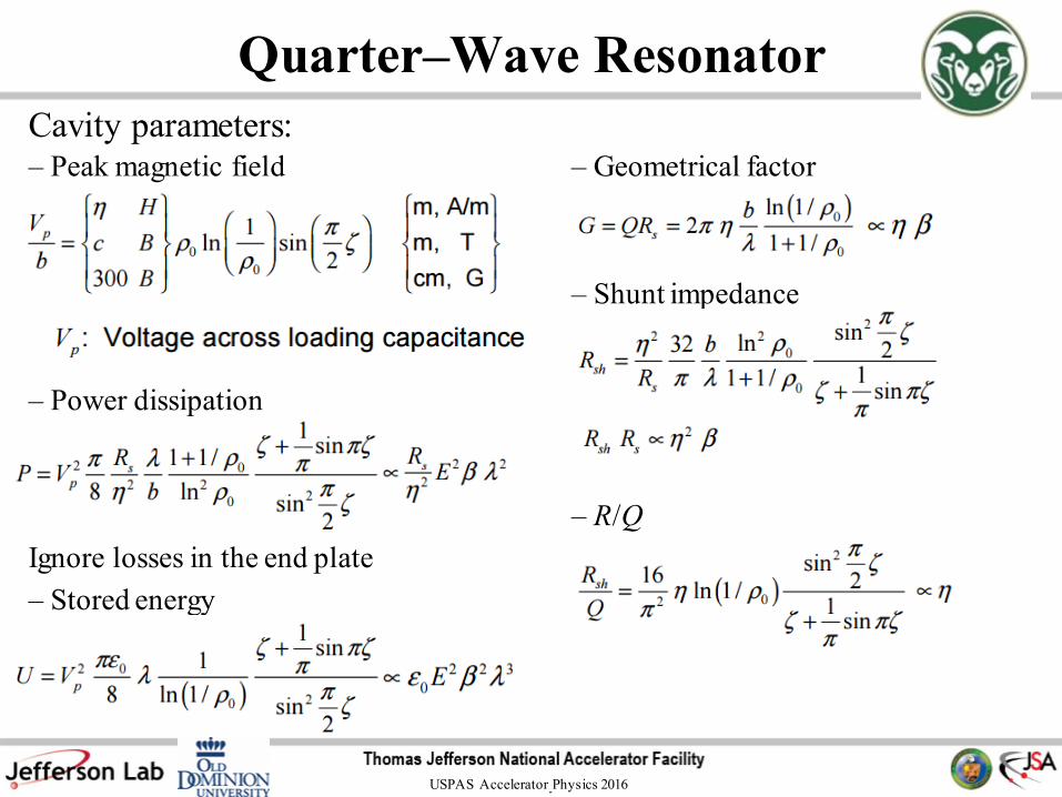
Quarter–Wave Resonator
Cavity parameters:– Peak magnetic field
– Power dissipation
Ignore losses in the end plate
– Stored energy
– Geometrical factor
– Shunt impedance
– R/Q
Page 61
USPAS Accelerator Physics June 2013USPAS Accelerator Physics 2016
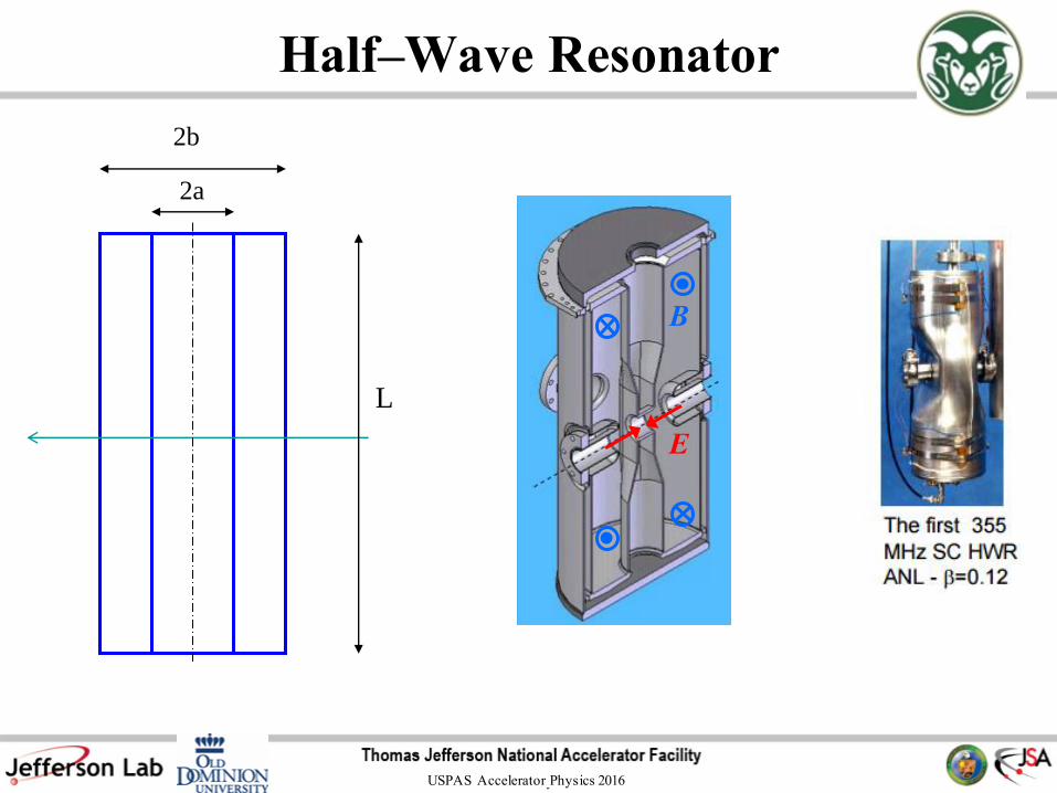
Half–Wave Resonator
2b
2a
L
E
B
Page 62
USPAS Accelerator Physics June 2013USPAS Accelerator Physics 2016
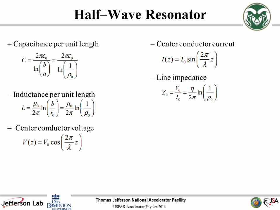
Half–Wave Resonator
– Capacitance per unit length
– Inductance per unit length
– Center conductor voltage
– Center conductor current
– Line impedance
Page 63
USPAS Accelerator Physics June 2013USPAS Accelerator Physics 2016
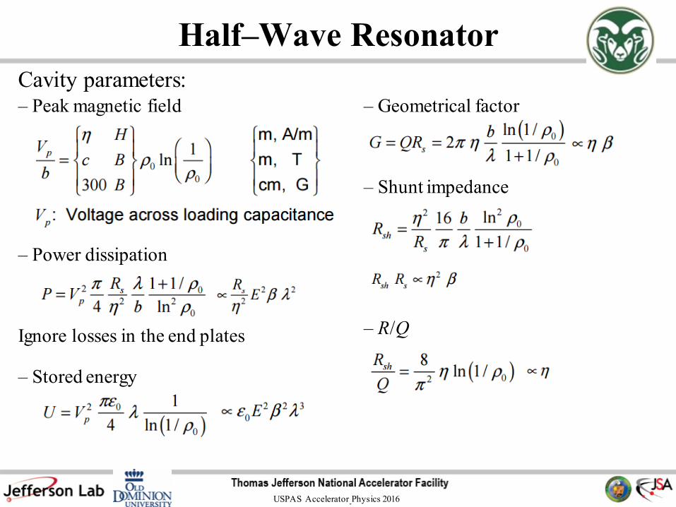
Half–Wave Resonator
Cavity parameters:– Peak magnetic field
– Power dissipation
Ignore losses in the end plates
– Stored energy
– Geometrical factor
– Shunt impedance
– R/Q
Page 64
USPAS Accelerator Physics June 2013USPAS Accelerator Physics 2016
There have been extensive efforts for design optimization especially to reduce
the ratios of
Ep/Eacc and Bp/Eacc
• Controlling A/B (Ep/Eacc) and C/D (Bp/Eacc) Shape optimization
• Flat contacting surface at spoke base will also help in minimization of Bp/Eacc
• For these cavities:
– Calculations agree well Ep/Eacc ~3, Bp/Eacc ~(7~8) mT/(MV/m)
– Though it is tricky to obtain precise surface field information from the
3D simulation
Spoke Resonators
325 MHz, β=0.17 (FNAL)
Page 65
USPAS Accelerator Physics June 2013USPAS Accelerator Physics 2016
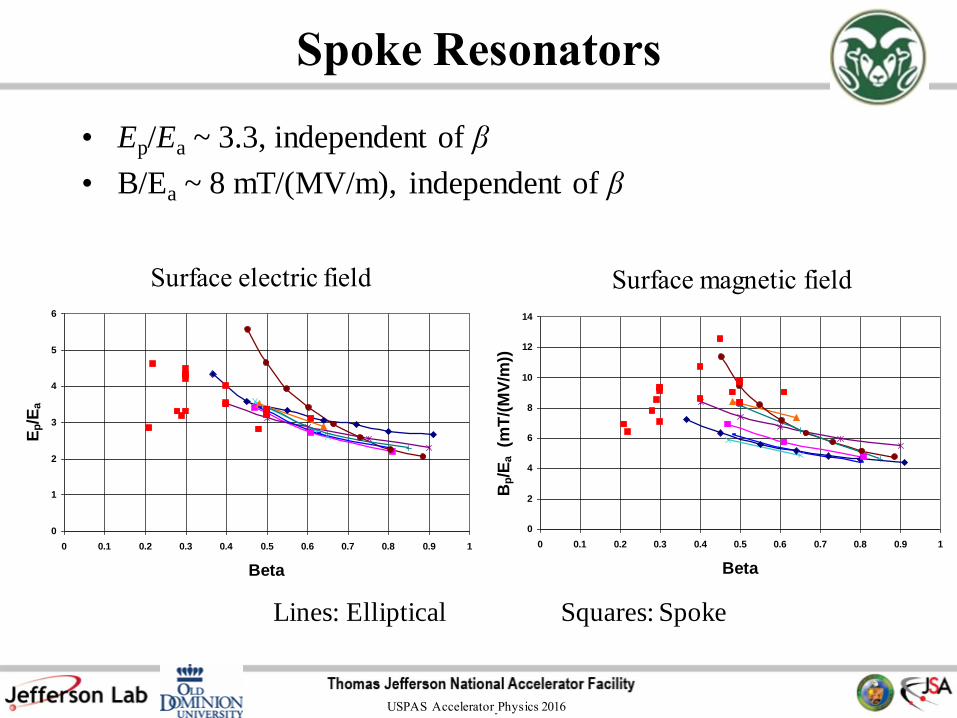
• Ep/Ea ~ 3.3, independent of β
• B/Ea ~ 8 mT/(MV/m), independent of β
Spoke Resonators
0
1
2
3
4
5
6
0 0.1 0.2 0.3 0.4 0.5 0.6 0.7 0.8 0.9 1
Beta
Ep/E
a
0
2
4
6
8
10
12
14
0 0.1 0.2 0.3 0.4 0.5 0.6 0.7 0.8 0.9 1
Beta
Bp/E
a (m
T/(
MV
/m))
Surface electric field Surface magnetic field
Lines: Elliptical Squares: Spoke
Page 66
USPAS Accelerator Physics June 2013USPAS Accelerator Physics 2016
• QRs ~ 200 [W]
• Rsh/Q ~ 205 [W], independent of
Spoke Resonators
Geometrical factor Rsh/Q
0
50
100
150
200
250
300
0 0.1 0.2 0.3 0.4 0.5 0.6 0.7 0.8 0.9 1
Beta
QR
s (W
)
0
50
100
150
200
250
300
350
0 0.1 0.2 0.3 0.4 0.5 0.6 0.7 0.8 0.9 1
Beta
Rsh/Q
per
cell (
W)
Lines: Elliptical Squares: Spoke
Page 67
USPAS Accelerator Physics June 2013USPAS Accelerator Physics 2016
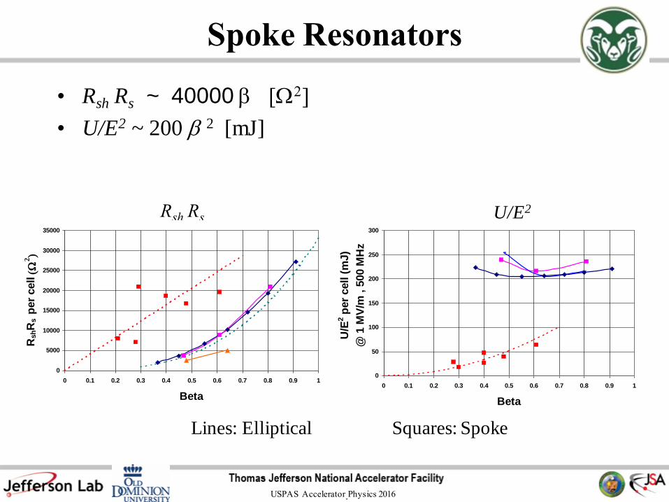
• Rsh Rs ~ 40000 [W2]
• U/E2 ~ 200 2 [mJ]
Spoke Resonators
Rsh Rs U/E2
Lines: Elliptical Squares: Spoke
0
5000
10000
15000
20000
25000
30000
35000
0 0.1 0.2 0.3 0.4 0.5 0.6 0.7 0.8 0.9 1
Beta
RshR
s p
er
cell
(W
2)
0
50
100
150
200
250
300
0 0.1 0.2 0.3 0.4 0.5 0.6 0.7 0.8 0.9 1
Beta
U/E
2 p
er
cell (
mJ)
@ 1
MV
/m , 5
00 M
Hz
Page 68
USPAS Accelerator Physics June 2013USPAS Accelerator Physics 2016
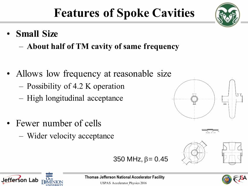
Features of Spoke Cavities
• Small Size
– About half of TM cavity of same frequency
• Allows low frequency at reasonable size
– Possibility of 4.2 K operation
– High longitudinal acceptance
• Fewer number of cells
– Wider velocity acceptance
350 MHz, = 0.45
Page 69
USPAS Accelerator Physics June 2013USPAS Accelerator Physics 2016USPAS Accelerator Physics 2016
Deflecting / Crabbing Cavities
Page 70
USPAS Accelerator Physics June 2013USPAS Accelerator Physics 2016
Deflecting Cavities
f0 = 1497 MHz
fd = 499 MHz
θ
E0
eVT
Beam direction
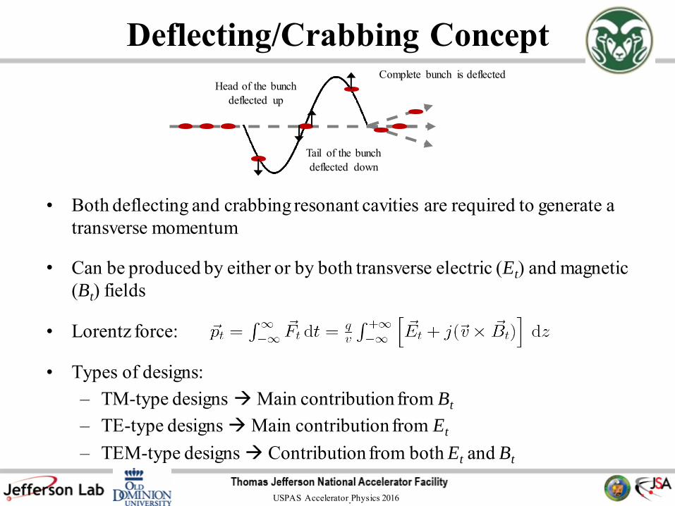
• Complete bunch is deflected with the
transverse kick applied at the center of the
bunch
• RF frequency (fd) = 499 MHz
• Beam energy (E) = 11.023 GeV
• Deflecting angle (θ)
• Transverse voltage (Vt)
Page 71
USPAS Accelerator Physics June 2013USPAS Accelerator Physics 2016
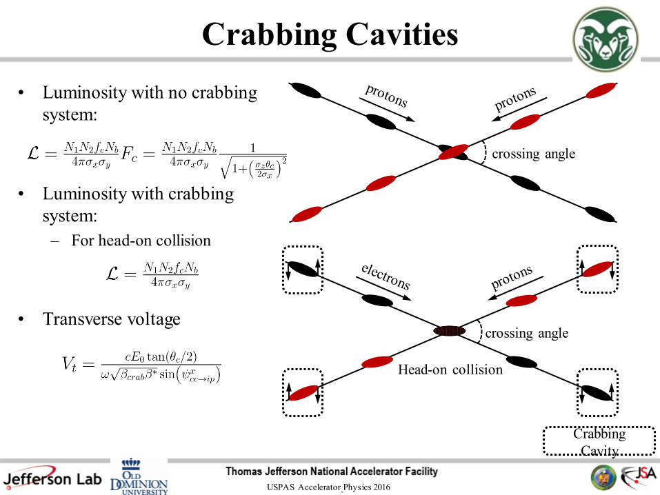
• Luminosity with no crabbing
system:
• Luminosity with crabbing
system:
– For head-on collision
• Transverse voltage
Crabbing Cavities
crossing angle
Crabbing
Cavity
Head-on collision
crossing angle
Page 72
USPAS Accelerator Physics June 2013USPAS Accelerator Physics 2016
• Both deflecting and crabbing resonant cavities are required to generate a
transverse momentum
• Can be produced by either or by both transverse electric (Et) and magnetic
(Bt) fields
• Lorentz force:
• Types of designs:
– TM-type designs Main contribution from Bt
– TE-type designs Main contribution from Et
– TEM-type designs Contribution from both Et and Bt
Deflecting/Crabbing Concept
Tail of the bunch
deflected down
Head of the bunch
deflected up
Complete bunch is deflected
Page 73
USPAS Accelerator Physics June 2013USPAS Accelerator Physics 2016
• For particles moving virtually at v=c, the integrated transverse force
(kick) can be determined from the transverse variation of the integrated
longitudinal force
• Transverse momentum is related to the gradient of the longitudinal
electric field along the beam axis
• According to the theorem:
– In a pure TE mode the contribution to the deflection from the
magnetic field is completely cancelled by the contribution from the
electric field
Panofsky–Wenzel Theorem
t t zj F Fc
Page 74
USPAS Accelerator Physics June 2013USPAS Accelerator Physics 2016
Deflecting/Crabbing Cavities
KEK TM110 crabbing cavity Superconducting 4-rod cavity
BNL double quarter-wave cavity
Page 75
USPAS Accelerator Physics June 2013USPAS Accelerator Physics 2016
Deflecting/Crabbing Cavities
Page 76
USPAS Accelerator Physics June 2013USPAS Accelerator Physics 2016
LHC High Luminosity Upgrade
Page 77
USPAS Accelerator Physics June 2013USPAS Accelerator Physics 2016USPAS Accelerator Physics 2016
Cavity Limitations
Page 78
USPAS Accelerator Physics June 2013USPAS Accelerator Physics 2016
Cavity Performance
Page 79
USPAS Accelerator Physics June 2013USPAS Accelerator Physics 2016
• Multipacting condition – A large amount of secondary
electrons are emitted from the cavity surface by the
incident primary electrons
Multipacting
Page 80
USPAS Accelerator Physics June 2013USPAS Accelerator Physics 2016
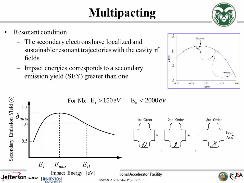
• Resonant condition
– The secondary electrons have localized and
sustainable resonant trajectories with the cavity rf
fields
– Impact energies corresponds to a secondary
emission yield (SEY) greater than one
Multipacting
δmax
EI Emax EII
Impact Energy [eV]
Sec
ondar
y E
mis
sio
n Y
ield
(δ)
IE 150eV
IIE 2000eVFor Nb:
Page 81
USPAS Accelerator Physics June 2013USPAS Accelerator Physics 2016
• Characterized by exponential decay in Q0
• Exponential increase of losses due to acceleration of electron field
emission
• With the increasing rf field the field emitters generate an electron current
leading to excessive heating and x-rays produced by bremsstrahlung
• It is a general difficulty in accelerating structures, but does not present an
ultimate fundamental limit to the maximum surface electric field
• Main cause of FE is particulate contamination
Field Emission
Temperature map shows line
heating along the longitude at
the location of the emitter
Page 82
USPAS Accelerator Physics June 2013USPAS Accelerator Physics 2016
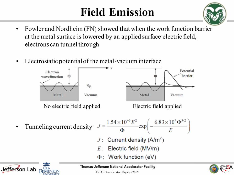
• Fowler and Nordheim (FN) showed that when the work function barrier
at the metal surface is lowered by an applied surface electric field,
electrons can tunnel through
• Electrostatic potential of the metal-vacuum interface
• Tunneling current density
Field Emission
No electric field applied Electric field applied
Page 83
USPAS Accelerator Physics June 2013USPAS Accelerator Physics 2016
• Modified Fowler Nordheim equation for rf fields
• Field emitters
Field Emission
• FE can be prevented by proper surface
preparation and contamination control
• Possible to reduce if not completely
eliminate FE using CW RF
processing, High-power Pulsed
Processing (HPP) and/or Helium
processing
Page 84
USPAS Accelerator Physics June 2013USPAS Accelerator Physics 2016
• Ponderomotive effects: changes in frequency caused by the
electromagnetic field (radiation pressure)
– Static Lorentz detuning (CW operation)
– Dynamic Lorentz detuning (pulsed operation)
• Microphonics: changes in frequency caused by connections
to the external world
– Vibrations
– Pressure fluctuations
• Note: The two are not completely independent. When phase
and amplitude feedbacks are active, the ponderomotive
effects can change the response to external disturbances
Ponderomotive Effects
Page 85
USPAS Accelerator Physics June 2013USPAS Accelerator Physics 2016
• Electromagnetic fields in a cavity exert Lorentz forces on the cavity wall. The
force per unit area (radiation pressure) is given by
Lorentz Force Detuning
-0.006
-0.003
0
0.003
0 20 40 60z [mm]
P [
N/m
m^
2]
E and H at Eacc =
25 MV/m in
TESLA inner-cup
50 MV/m
92 kA/m
• Residual deformation of the cavity shape shifts the
resonant frequency
kL – Lorentz coefficient
Page 86
USPAS Accelerator Physics June 2013USPAS Accelerator Physics 2016
• Localized heating
• Thermal breakdown occurs when the heat generated at the hot spot is
larger than that can be evacuated to the helium bath
• Both the thermal conductivity and the surface resistance of Nb are
highly temperature dependent between 2 and 9K
Thermal Breakdown
Page 87
USPAS Accelerator Physics June 2013USPAS Accelerator Physics 2016USPAS Accelerator Physics 2016
Losses in RF Cavities
Page 88
USPAS Accelerator Physics June 2013USPAS Accelerator Physics 2016
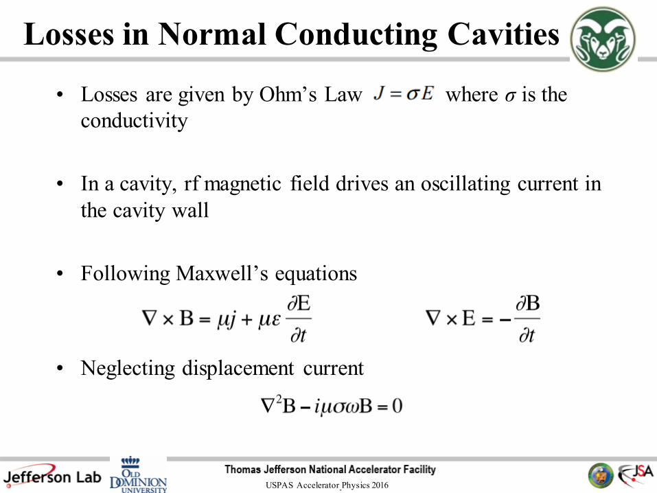
• Losses are given by Ohm’s Law where σ is the
conductivity
• In a cavity, rf magnetic field drives an oscillating current in
the cavity wall
• Following Maxwell’s equations
• Neglecting displacement current
Losses in Normal Conducting Cavities
Page 89
USPAS Accelerator Physics June 2013USPAS Accelerator Physics 2016
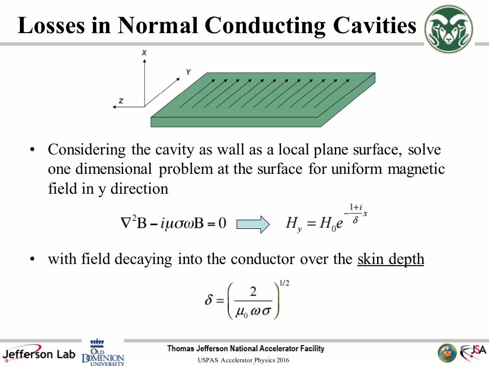
• Considering the cavity as wall as a local plane surface, solve
one dimensional problem at the surface for uniform magnetic
field in y direction
• with field decaying into the conductor over the skin depth
Losses in Normal Conducting Cavities
Page 90
USPAS Accelerator Physics June 2013USPAS Accelerator Physics 2016
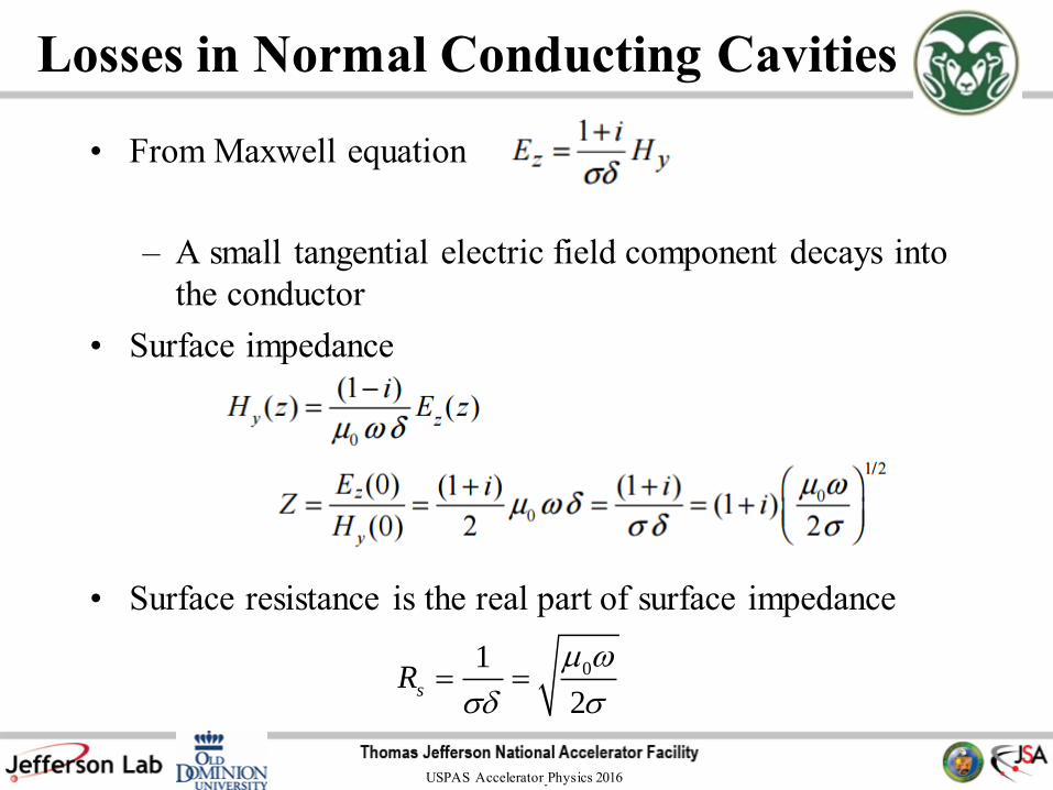
• From Maxwell equation
– A small tangential electric field component decays into
the conductor
• Surface impedance
• Surface resistance is the real part of surface impedance
Losses in Normal Conducting Cavities
01
2sR
Page 91
USPAS Accelerator Physics June 2013USPAS Accelerator Physics 2016
• Superconductivity – Discovered in 1911 Kammerlingh-Onnes, is
a phenomenon where below a certain temperature, called the
critical temperature (Tc), some materials show a sudden drop of
the dc electrical resistance to zero
Superconductivity
Kamerlingh Onnes and van der Waals in
Leiden with the helium 'liquefactor' (1908)
Page 92
USPAS Accelerator Physics June 2013USPAS Accelerator Physics 2016
Meissner Effect – Discovered by Meissner and Ochsenfeld in 1933
• Ability to completely expel an externally applied magnetic field when cooled
down below the critical temperature (Tc)
• Superconductor behaves as a perfect diamagnet
Meissner Effect
• Surface currents created at the
surface generates a magnetic field
that cancels the external magnetic
field inside the superconductor
• These surface currents do not
decay with time due to the zero
resistance in the superconductor
Page 93
USPAS Accelerator Physics June 2013USPAS Accelerator Physics 2016
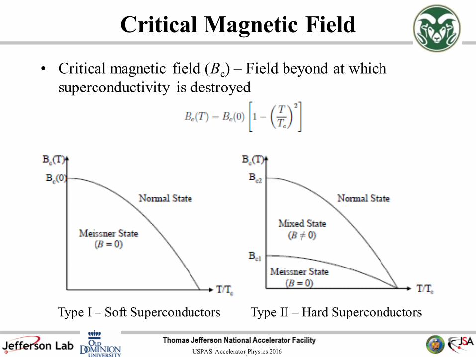
• Critical magnetic field (Bc) – Field beyond at which
superconductivity is destroyed
Critical Magnetic Field
Type I – Soft Superconductors Type II – Hard Superconductors
Page 94
USPAS Accelerator Physics June 2013USPAS Accelerator Physics 2016
• Meissner state in superconductor is an ideal diamagnet
• Magnetization:
• Complete Meissner state - Type I superconductor
• Partial Meissner state – Type II superconductor
Magnetization
Page 95
USPAS Accelerator Physics June 2013USPAS Accelerator Physics 2016
• Gorter and Casimir (1934) – Two Fluid Model
– London equations by F. London and H. London (1935)
London Penetration Depth (λ)
– Non local generalization to London equations by
Pippard Pippard Coherence Length (ξ)
• Ginzburg Landau Theory (1950)
– Second order phase transition of complex order
parameter (Ψ)
• BCS Theory (Bardeen Cooper Schrieffer) (1957)
– Microscopic theory
– Two fluid mode revised
Theories of Superconductivity
Page 96
USPAS Accelerator Physics June 2013USPAS Accelerator Physics 2016
• Macroscopic theory of superconductivity
• Coexistence of:
– super electrons (ns)
– normal electrons (nn)
– Total density
• Only super electrons are accelerated by the
constant electric field (E)
• Super current density
• Yields First London Equation
• Super electrons are not affected by the normal
electrons
Two Fluid Model
Page 97
USPAS Accelerator Physics June 2013USPAS Accelerator Physics 2016
• Using Maxwell’s equations
• Yield Second London Equation
• Field penetration in the superconductor
• London penetration depth
London Equations
Page 98
USPAS Accelerator Physics June 2013USPAS Accelerator Physics 2016
• London penetration depth (λL)
– Distance over which magnetic fields decay in
superconductors
• Pippard coherence length (ξ0)
– Distance over which the superconducting state decays
Fundamental Lengths
• Type II
superconductors –
λL >> ξ0
• Type I
superconductors –
ξ0 >> λL
Page 99
USPAS Accelerator Physics June 2013USPAS Accelerator Physics 2016
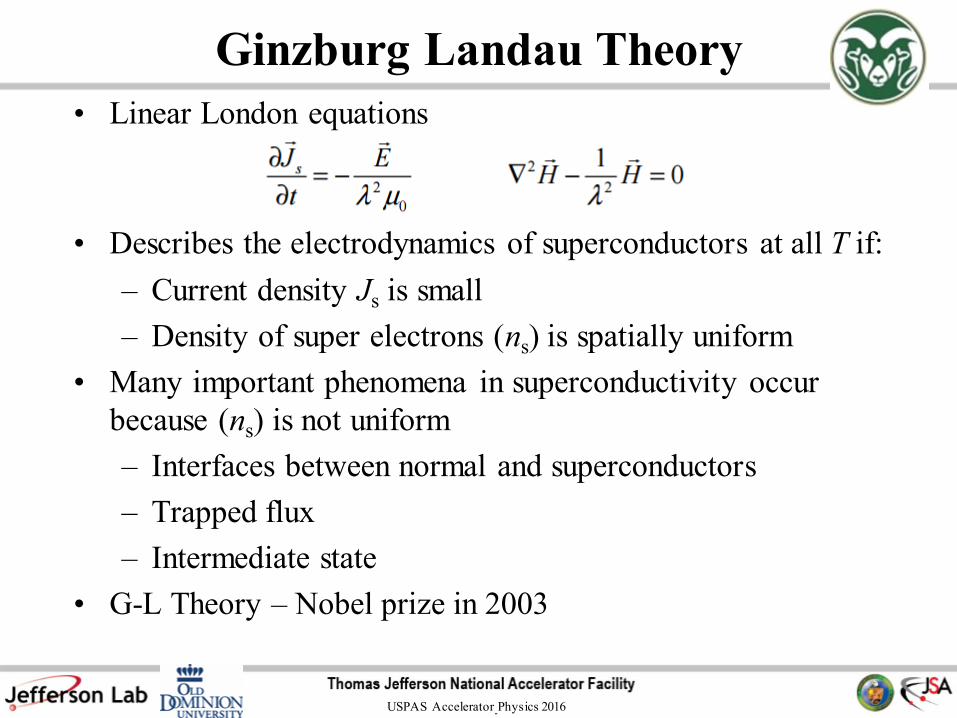
• Linear London equations
• Describes the electrodynamics of superconductors at all T if:
– Current density Js is small
– Density of super electrons (ns) is spatially uniform
• Many important phenomena in superconductivity occur
because (ns) is not uniform
– Interfaces between normal and superconductors
– Trapped flux
– Intermediate state
• G-L Theory – Nobel prize in 2003
Ginzburg Landau Theory
Page 100
USPAS Accelerator Physics June 2013USPAS Accelerator Physics 2016
• G-L Theory – Generalization of London equations to
nonlinear problems but still retain the local approximation
of the electrodynamics
• Theory of second order phase transition is based on an
order parameter which is zero above the transition
temperature and non-zero below
• For superconductors, G-L theory uses a complex order
parameter ψ(r) such that |ψ(r)|2 represents the density of
super electrons
φ(r) is the phase
Ginzburg Landau Theory
Page 101
USPAS Accelerator Physics June 2013USPAS Accelerator Physics 2016
• London penetration depth:
• Coherence length:
• GL parameter: κ = λ(T)/ξ(T) is independent of T
• Critical field Hc(T)
Ginzburg Landau Theory
Page 102
USPAS Accelerator Physics June 2013USPAS Accelerator Physics 2016
Material Parameters
Page 103
USPAS Accelerator Physics June 2013USPAS Accelerator Physics 2016
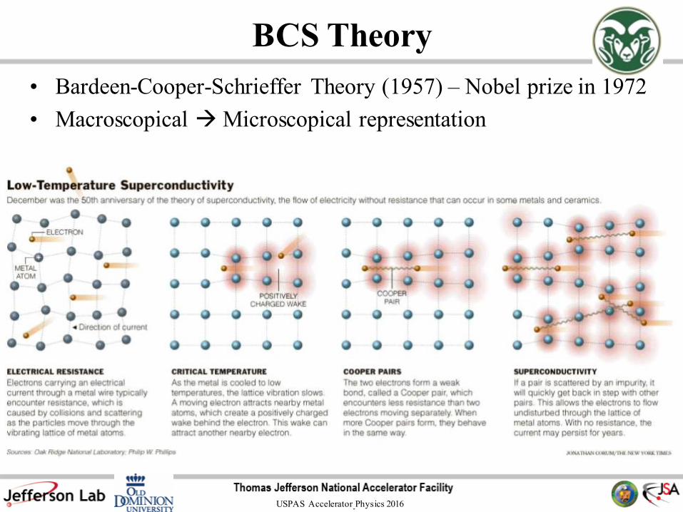
• Bardeen-Cooper-Schrieffer Theory (1957) – Nobel prize in 1972
• Macroscopical Microscopical representation
BCS Theory
Page 104
USPAS Accelerator Physics June 2013USPAS Accelerator Physics 2016
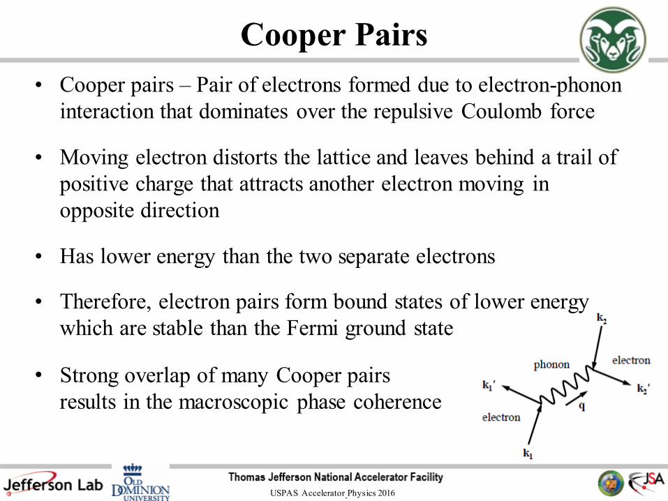
• Cooper pairs – Pair of electrons formed due to electron-phonon
interaction that dominates over the repulsive Coulomb force
• Moving electron distorts the lattice and leaves behind a trail of
positive charge that attracts another electron moving in
opposite direction
• Has lower energy than the two separate electrons
• Therefore, electron pairs form bound states of lower energy
which are stable than the Fermi ground state
Cooper Pairs
• Strong overlap of many Cooper pairs
results in the macroscopic phase coherence
Page 105
USPAS Accelerator Physics June 2013USPAS Accelerator Physics 2016
• Energy gap (Δ) – gap around Fermi level between ground
state and excited state
Energy Gap
Normal
conductorSuperconductor
• At 0 < T < Tc not all electrons are
bounded in to Cooper pairs
• Density of unpaired electrons is given
by
Page 106
USPAS Accelerator Physics June 2013USPAS Accelerator Physics 2016
• At the presence of an rf field
– Cooper pairs move without resistance Do not
dissipate power
– Due to inertial mas of Cooper pairs they cannot follow
an AC electromagnetic fields instantly and do not
shield it perfectly
– Remaining residual field accelerates the normal
electrons that dissipate power
• More normal electrons The material is more lossy
– Losses decrease with temperature below Tc
• Faster the field oscillates the less perfect the shielding
– Losses increase with frequency
Losses in Superconductor
Page 107
USPAS Accelerator Physics June 2013USPAS Accelerator Physics 2016
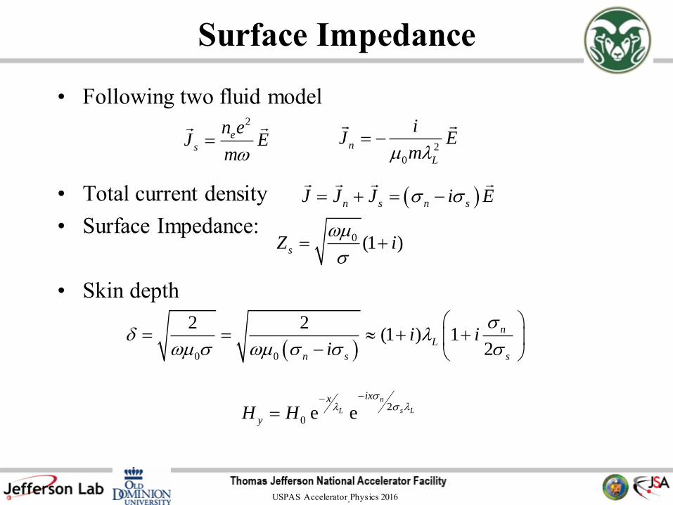
• Following two fluid model
• Total current density
• Surface Impedance:
• Skin depth
Surface Impedance
2
e
s
n eJ E
m 2
0
n
L
iJ E
m
( )n s n sJ J J i E
0 (1 )sZ i
( )0 0
2 2(1 ) 1
2
n
L
n s s
i ii
2
0 e en
s LL
ixx
yH H
Page 108
USPAS Accelerator Physics June 2013USPAS Accelerator Physics 2016
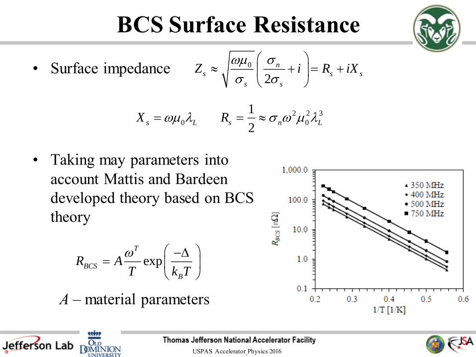
• Surface impedance
• Taking may parameters into
account Mattis and Bardeen
developed theory based on BCS
theory
A – material parameters
BCS Surface Resistance
0
2
n
s s s
s s
Z i R iX
2 2 3
0 0
1
2s L s n LX R
expT
BCS
B
R AT k T
Page 109
USPAS Accelerator Physics June 2013USPAS Accelerator Physics 2016
• Surface resistance of superconductors (Rs)
• Residual resistance (Rres) due to:
– Dielectric surface contaminants (gases, chemical residues, ..)
– Normal conducting defects, inclusions
– Surface imperfections (cracks, scratches, ..)
– Trapped flux during cool down through critical temperature
– Hydrogen absorption during chemical processing
• An approximation of RBCS for Nb:
Surface Resistance
2
4 [GHz] 1 17.672 10 exp [ ]
1.5BCS
fR
T T
W
[ ]s BCS resR R R W