WARM AIR FURNACE MULTIPOSITION Printed in Canada Printed on 100% recycled paper INSTALLER / SERVICE TECHNICIAN : USE THE INFORMATION IN THIS MANUAL FOR THE INSTALLATION / SERVICING OF THE FURNACE AND KEEP THE DOCUMENT NEAR THE UNIT FOR FUTURE REFERENCE. HOMEOWNER: PLEASE KEEP THIS MANUAL NEAR THE FURNACE FOR FUTURE REFERENCE. Attention : Do not tamper with the unit or its controls. Call a qualified service technician. Models: AMP105-IE2 AMP120-IE2 NOMF105D12C NOMF155E19C NOMF106D12B NOMF156E19C 2011-06-02 X40002 Rev.V Manufactured by: Dettson Industries inc. 3400 Industriel Boulevard Sherbrooke, Quebec - Canada J1L 1V8 DNS-0376 Rév. A C US
Transcript
WARM AIR FURNACEMULTIPOSITION
Printed in CanadaPrinted on 100% recycled paper
INSTALLER / SERVICE TECHNICIAN:USE THE INFORMATION IN THIS MANUAL FOR THE INSTALLATION / SERVICING OF THE FURNACE AND KEEP THE DOCUMENT NEAR THE UNIT FOR FUTURE REFERENCE.
HOMEOWNER:PLEASE KEEP THIS MANUAL NEAR THE FURNACE FOR FUTURE REFERENCE.
Attention:Do not tamper with the unit or its controls.Call a qualified service technician.
DO NOT STORE OR USE GASOLINE OR OTHER FLAMMABLE VAPOURS AND LIQUIDS IN THE VICINITY OF THIS OR ANY OTHER APPLIANCE. DO NOT ATTEMPT TO START THE BURNER WHEN EXCESS OIL HAS ACCUMULATED, WHEN THE FURNACE IS FULL OF VAPOUR OR WHEN THE COMBUSTION CHAMBER IS VERY HOT. 1.1 DANGER, WARNING AND CAUTION The words DANGER, WARNING and CAUTION are used to identify the levels of seriousness of certain hazards. It is important that you understand their meaning. You will notice these words in the manual as follows:
DANGER
Immediate hazards which WILL result in death or serious bodily and/or material damage.
WARNING
Hazards or unsafe practices which CAN result in death or serious bodily and/or material damage.
CAUTION Hazards or unsafe practices which CAN result in minor bodily and/or material damage.
WARNING For use with grade 2 Fuel Oil maximum. Do not use gasoline, crankcase oil or any oil containing gasoline!
WARNING Never burn garbage or paper in the heating system and never leave rags or paper around the unit.
CAUTION These instructions are intended for use by qualified personnel having been trained in installing this type of furnace. Installation of this furnace by an unqualified person may lead to equipment damage and/or hazardous conditions, which may lead to bodily harm. IMPORTANT: Please refer to the Sealed Combustion System Manual for installation instructions. The furnace must be installed in an upflow position when used with a Sealed Combustion System.
IMPORTANT: All local and national code requirements governing the installation of oil burning equipment, wiring and flue connections must be followed. Some of the codes that may be applicable are: CSA B139 Installation Code for Oil Burning
Equipment ANSI/NFPA 31 Installation of Oil Burning Equipment ANSI/NFPA 90B Warm Air Heating and Air Conditioning
Systems ANSI/NFPA 211 Chimneys, Fireplaces, Vents and Solid
Fuel Burning Appliances ANSI/NFPA 70 National Electrical Code CSA C22.2 No.3 Canadian Electrical Code Only the latest issues of the above codes should be used, and are available from either: The National Fire Protection Agency 1 Batterymarch Park Quincy, MA 02269 or The Canadian Standards Association 178 Rexdale Blvd. Rexdale, Ontario M9W 1R3 1.2 GENERAL This central heating unit is a true multi-position unit, in that it can operate in four different configurations, i.e., upflow, counter flow (downflow), and horizontal (both left-to-right and right-to-left airflow).
Very few modifications are required during installation, to change the furnace from one configuration to another. The furnace is shipped in the upflow configuration; however, instructions on how to change to the other configurations are included in this manual.
4
The furnace is shipped complete with burner and controls. It requires a 115VAC line voltage connection to the control panel, thermostat hook-up as shown on the wiring diagram, one or more oil line connections, suitable ductwork and connection to a properly sized vent.
The air handling capacity of this furnace is designed for cooling as well. Please refer to Table 4, p. 14 for the expected airflow at various external static pressures. 1.3 LOCATION
The unit must be installed in a location where the ambient and return air temperature is over 15°C (60°F).
WARNING This furnace is not watertight and is not designed for outdoor installation. This furnace shall be installed in such a manner as to protect the electrical components from water. Outdoor installation will lead to a hazardous electrical condition and to premature furnace failure.
CAUTION If this furnace is installed in an attic, it is important to keep insulation at least 0.3 m (12") away from any furnace openings. Some types of insulating material may be combustible. This furnace is approved for reduced clearances to combustible construction. Therefore, it may be installed in a closet or similar enclosure. As this unit may be installed as an upflow, counter flow, or horizontal furnace, it may be located in a basement, on the same level as the area to be heated, suspended, or in a crawlspace. In any case, the unit should always be installed level.
In a basement, or when installed on the floor (as in a crawlspace), it is recommended that the unit be installed on a concrete pad that is 2.5 cm to 5.0 cm (1" to 2") thick.
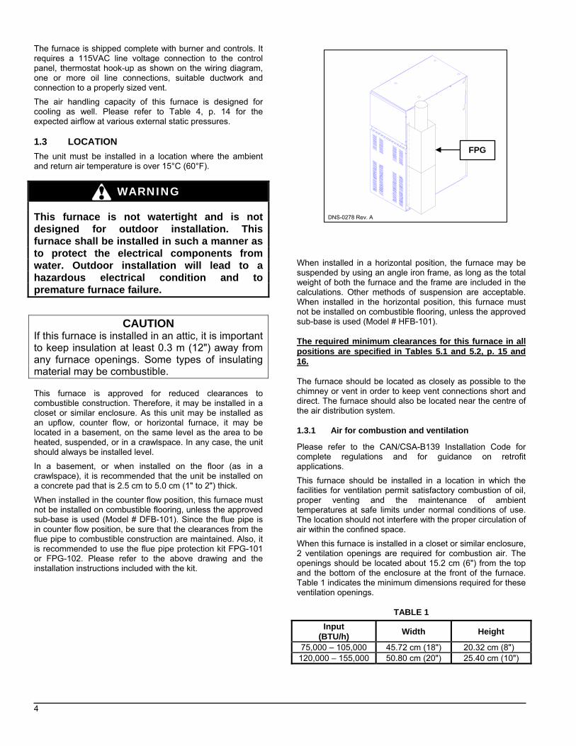
When installed in the counter flow position, this furnace must not be installed on combustible flooring, unless the approved sub-base is used (Model # DFB-101). Since the flue pipe is in counter flow position, be sure that the clearances from the flue pipe to combustible construction are maintained. Also, it is recommended to use the flue pipe protection kit FPG-101 or FPG-102. Please refer to the above drawing and the installation instructions included with the kit.
When installed in a horizontal position, the furnace may be suspended by using an angle iron frame, as long as the total weight of both the furnace and the frame are included in the calculations. Other methods of suspension are acceptable. When installed in the horizontal position, this furnace must not be installed on combustible flooring, unless the approved sub-base is used (Model # HFB-101). The required minimum clearances for this furnace in all positions are specified in Tables 5.1 and 5.2, p. 15 and 16. The furnace should be located as closely as possible to the chimney or vent in order to keep vent connections short and direct. The furnace should also be located near the centre of the air distribution system. 1.3.1 Air for combustion and ventilation Please refer to the CAN/CSA-B139 Installation Code for complete regulations and for guidance on retrofit applications.
This furnace should be installed in a location in which the facilities for ventilation permit satisfactory combustion of oil, proper venting and the maintenance of ambient temperatures at safe limits under normal conditions of use. The location should not interfere with the proper circulation of air within the confined space.
When this furnace is installed in a closet or similar enclosure, 2 ventilation openings are required for combustion air. The openings should be located about 15.2 cm (6") from the top and the bottom of the enclosure at the front of the furnace. Table 1 indicates the minimum dimensions required for these ventilation openings.
TABLE 1 Input
(BTU/h) Width Height
75,000 – 105,000 45.72 cm (18") 20.32 cm (8") 120,000 – 155,000 50.80 cm (20") 25.40 cm (10")
DNS-0278 Rev. A
FPG
5
WARNING
Do not block the combustion air openings in the furnace. Any blockage will result in improper combustion and may result in a fire hazard and/or cause bodily harm. For chimney application, the barometric draft regulator included with the furnace, shall be installed in the same room or enclosure as the furnace, in such a manner as to prevent any difference in pressure between the regulator and the combustion air supply.
Air requirements for the operation of exhaust fans, kitchen ventilation systems, clothes dryers, and fireplaces shall be considered in determining the adequacy of the space to provide combustion air requirements.
In unconfined spaces, in buildings of conventional frame, brick or stone construction, infiltration may be adequate to provide air for combustion, ventilation and dilution of flue gases. This determination must be made on an individual installation basis and must take into consideration the overall volume of the unconfined space, the number of windows and ventilation openings, the number of doors to the outside, internal doors which can close off the unconfined space and the overall air tightness of the building construction.
Many new buildings and homes (and older ones that have been weatherized must be considered as being tight construction and, therefore, infiltration will not be sufficient to supply the necessary air for combustion and ventilation.
A building can be considered as being of tight construction when: a. Walls and ceilings exposed to the outside have a
continuous water vapour retarder with a rating of one perm or less, openings have gaskets or are sealed and/or;
b. Weather-stripping has been added on operable windows and doors, and/or;
c. Caulking or sealant has been applied to areas such as joints around window and doorframes, between sole plates and floors, between wall-ceiling joints, between wall panels, at penetrations for plumbing, electrical and fuel lines and at other openings.
1.3.2 Duct recommendations
WARNING
When ducting supplies air to a space other than where the furnace is located, the return air must be sealed and also be directed to the space other than where the furnace is located. Incorrect ductwork termination and sealing will create a hazardous condition that can lead to bodily harm.
CAUTION Return air grilles and warm air registers must not be obstructed. IMPORTANT: The dampers should be adequate to prevent cooled air from entering the furnace, and if manually operated, must be equipped with the means to prevent operation of either the cooling unit or the furnace, unless the damper is in the full cool or heat position.
NOTE: THE BACK SHOULD NOT BE CUT OUT FOR RETURN AIR DUCTING
The proper sizing of warm air ducts is necessary to ensure satisfactory furnace operation. Ductwork should be in accordance with the latest editions of NFPA-90A (Installation of Air Conditioning and Ventilating Systems) and NFPA-90B (Warm Air Heating and Air Conditioning Systems) or Canadian equivalent.
The supply ductwork should be attached to the flanged opening provided at the discharge end of the furnace. See Figures 7.1 & 7.2, p.15 and 16, for the dimensions of this opening.
Knockouts are provided on both sides of the furnace to cut the required size of opening for the installation of the return air ductwork. This can be done on either the right or the left side of the furnace. See Table 2, p. 9, for location and dimensions.
Also, there is provision on this furnace for a bottom return air duct. Knockouts are provided in the floor of the furnace to facilitate the cut-out requirement for the air filter rack and return ductwork. (We recommend the use of this opening for horizontal and counterflow installations).
The following recommendations should be followed when installing ductwork: a. Install locking type dampers in all branches of the
individual ducts to facilitate balancing the system. Dampers should be adjusted such a way as to ensure the proper static pressure at the outlet of the furnace;
b. A flexible duct connector of non-combustible material should be installed at the unit on both the supply and return air side. In applications where an extremely quiet operation is necessary, the first 3 m (10') of supply and return ducts should be internally lined with acoustical material (if possible);
c. In cases where the return air grille is located close to the fan inlet, there should be at least one 90o turn between fan inlet and grille. Further reduction in sound level can be accomplished by installing acoustical turning vanes or lining the duct as described in item b. above;
d. When a single air grille is used, the duct between grille and furnace must be the same size as the return air opening in the furnace.
When installing the furnace with cooling equipment for year round operation, the following recommendations must be followed for tandem or parallel air flow:
a. On tandem airflow applications, the coil is mounted after the furnace in an enclosure in the supply air stream. The furnace blower is used for both heating and cooling airflow;
6
b. On parallel airflow installation, dampers must be provided to direct air over the furnace heat exchanger when heat is desired and over the cooling coil when cooling is desired.
WARNING
The coil MUST be installed on the air discharge side of the furnace. Under no circumstances should the airflow be such that cooled, conditioned air is allowed to pass over the furnace heat exchanger. This will cause condensation in the heat exchanger and possible failure of same, which could result in a fire hazard and/or other hazardous conditions that may lead to bodily harm. Heat exchanger failure due to improper installation may not be covered by the warranty. 1.3.3 Venting instructions Venting of the furnace must be to the outside and in accordance with local codes and/or requirements of local authorities.
OIL FIRED APPLIANCES INSTALLED WITH CHIMNEY SHALL BE CONNECTED TO FLUES HAVING SUFFICIENT DRAFT AT ALL TIMES TO ENSURE SAFE AND PROPER OPERATION OF THE APPLIANCE.
For additional venting information please refer to ANSI/NFPA 211 Chimneys, Fireplaces, Vents and Solid Fuel Burning Appliances and/or the CSA B139 Installation Code.
This furnace is certified for use with a Type “L” vent (maximum flue gas temperature 302°C (575°F)). The flue pipe clearance knockout in the front top or side panel should be removed. Install the flue elbow so that it exits the furnace cabinet through that opening. Pre-installation vent system inspection Before this furnace is installed, it is strongly recommended that any existing vent system be completely inspected.
On any chimney or vent, this should include the following: a. Inspection for any deterioration in the chimney or vent. If
deterioration is discovered, the chimney must be repaired or the vent replaced;
b. Inspection to ascertain that the vent system is clear and free of obstructions. Any blockages must be removed before installing this furnace;
c. Cleaning the chimney or vent if previously used for venting a solid fuel burning appliance or fireplace;
d. Confirming that all unused chimney or vent connections are properly sealed;
e. Verification that the chimney is properly lined and sized per the applicable codes. (Please refer to list of codes on page 3)
Masonry Chimneys This furnace may be vented into an existing masonry chimney. However, it must not be vented into a chimney servicing a solid fuel-burning appliance. Before venting this furnace into a chimney, the chimney must be checked for deterioration and repaired if necessary. The chimney must be properly lined and sized per local and/or national codes.
If the furnace is vented into a common chimney, the chimney must be of sufficient area to accommodate the total flue products of all appliances vented into the chimney.
The following requirements are provided for a safe venting system: a. Ensure that the chimney flue is clear of any dirt or
debris; b. Ensure that the chimney is not servicing an open
fireplace; c. Never reduce the pipe size below the outlet size of the
furnace; d. All pipes should be supported, using the proper clamps
and/or straps. These supports should be installed at least every 4 feet;
e. All horizontal runs of pipe should have at least 6.4 mm (1/4”) of upward slope per 0.3 m (1');
f. All runs of pipe should be as short as possible with as few turns as possible;
g. Seams should be tightly joined and checked for leaks; h. The flue pipe must not extend into the chimney but be
flush with the inside wall; i. The chimney must extend 0.9 m (3') above the highest
point where it passes through a roof of a building and at least 0.6 m (2') higher than any portion of a building within a horizontal distance of 3 m (10'). It shall also be extended at least 1.5 m (5') above the highest connected equipment flue collar;
j. Check local codes for any variances.
Factory Built Chimneys
Approved factory built chimneys may be used. Refer to chimney manufacturer’s instructions for proper installation.
1.3.4 Draft Regulator (Chimney venting)
The draft regulator supplied with the furnace must be used for proper functioning. Installation instructions are included with the control.
1.3.5 Blocked vent shut-off (BVSO) For chimney venting
WARNING It is imperative that this device be installed by a qualified agency.
This device is designed to detect the insufficient evacuation of combustion gases in the event of a vent blockage. In such a case the thermal switch will shut down the oil burner. The device will then need to be re-armed MANUALLY.
Please refer to Figures 1 to 6, p. 7 & 8, the wiring diagrams on pages 17 and 18 and the detailed instructions supplied with the BVSO for the installation and wiring procedures. The length of wires supplied with the unit is such that the safety device must be installed between the flue outlet of the appliance and the draft regulator, as indicated in the instructions.
It is also essential that the BVSO be maintained annually. For more details please refer to the instructions supplied with the device itself, as well as Section 3 of this Manual.
CAUTION A positive pressure venting system (Sealed Combustion System or Direct Vent) MUST NOT use the BVSO. Follow the instructions supplied with the venting system.
7
Blocked Vent Shut-Off device wiring
Installation shown: Upflow with vertical exhaust
Use the three wire fasteners. The wires must not come in contact with the flue and cleaning pipes.
Connect the green ground wire to a cabinet screw.
Connect the wires to the free Limit Control terminals.
FIGURE 1
The position of the hole in the vent is subject to the length of the electrical kit.
Blocked Vent Shut-Off device BVSO.
Electrical kit supplied.
DNS-1043 Rev. A2
FIGURE 2
Blocked Vent Shut-Off device wiring Installation: Upflow with horizontal exhaust
FIGURE 3
Blocked Vent Shut-Off device wiring Installation: Upflow with vertical exhaust
Please refer to the Sealed Combustion System or Direct Vent System instruction manuals. 1.3.7 Oil burner This furnace is equipped with a high pressure atomizing retention head type burner for use with not heavier than grade 2 Fuel Oil. The mounting flange is fixed to the burner air tube and no adjustment is required for insertion length.
CAUTION NEVER use the “interrupted ignition” function if a Beckett AFG burner is installed on the furnace. Oil Connections Complete instructions for installation of the fuel oil piping will be found in the oil burner installation instructions included with the furnace. Oil line entry holes are located in the side panels. Two holes are provided on each side, so that a two-pipe system can be used if desired. A 10-micron (or finer) oil filter should be used with all oil burners, installed as closely as possible to the burner. 1.3.8 Electrical system The appliance must be installed in accordance with the current ANSI/NFPA 70 National Electrical Code, CSA C22.1 Canadian Electrical Code Part 1 and/or local codes. The control system depends on the correct polarity of the power supply. Connect “HOT” wire (H) and “NEUTRAL” wire (N) as shown in Figures 8.1 to 8.2, p. 17 and 18. A separate line voltage supply should be used with fused disconnect switch or circuit breaker between the main power panel and the unit.
WARNING
The unit cabinet must have an uninterrupted or unbroken electrical ground to minimize personal injury if an electrical fault should occur. A green ground screw is provided in the control box for this connection. Use only copper wire for 115V supply service to the unit.
Metallic conduit (where required/used) may terminate at the side panel of the unit. It is not necessary to extend the conduit inside the unit from the side panel to the control box.
When replacing any original furnace wiring, use only 105oC, 16 AWG copper wire.
Instructions for wiring the thermostat are provided with the thermostat (field supplied). Wire the connections to the 24-volt terminal board on the primary relay as shown in Figures 8.1 to 8.2, p. 17 & 18.
When installing optional accessories to this appliance, follow the manufacturer’s installation instructions included with the accessory. Other than wiring for the thermostat, wire with a minimum of type “T” insulation (17oC rise (63oF)) must be used for accessories. 1.3.9 Air filter
An external filter rack is provided as standard equipment with this furnace. The filter rack can be installed on the right or left side panel, or on the bottom of the furnace to accommodate the return air ductwork. A sufficient clearance should be provided for air filter access. Please refer to Table 2 for filter rack flange dimensions for return air duct.
TABLE 2 Furnace Model
Air Filter Size
Flange Opening
40.64 x 60.96 cm 38.10 X 58.42 cm AMP & NOMF (105 & 106) 16" x 24" 15" x 23"
45.72 X 76.20 cm 43.18 X 73.66 cm AMP & NOMF (120, 155 & 156) 20" x 30" 17" x 29"
1.3.10 Air Conditioner (or Heat Pump)
An air conditioning coil may be installed on the supply air side ONLY.
WARNING
Poisonous carbon monoxide gas hazard.
Install the evaporator coil on the supply side of the furnace ducting ONLY.
An evaporator coil installed on the return air side of the ducting can cause condensation to form inside the heat exchanger, resulting in heat exchanger failure. This in turn can result in death, bodily injury No minimum clearance is required between the bottom of the coil drain pan and the top of the heat exchanger. If a heat pump is installed, a “dual-energy” thermostat, or other control is required, in order to prevent the simultaneous operation of the furnace and the heat pump. It also prevents a direct transition from heating by way of the heat pump to heating with oil. Refer to the thermostat instructions or those of another control used for the proper wiring. If a coil blower compartment is used, install air tight, motorized and automatic air dampers. Cold air coming from the coil and passing across the furnace can cause condensation and shorten the life of the heat exchanger. 1.3.11 Horizontal or downflow installation
1. On horizontal installations, determine which “side” will become the “top”, when the unit is laid down. Remove the flue pipe clearance knockout from the top front of that side panel. Install the flue elbow so that it exits the cabinet of the furnace through that opening;
10
2. On counterflow Installations, the flue pipe must exit the cabinet through one of the side panel openings (as above), then extended up the side of the furnace. Ensure that adequate clearances to combustibles are observed. It may be necessary to install a sheet-metal shield on an adjacent wall to prevent any possibility of a fire hazard;
3. Remove the burner by loosening the mounting nuts and turn the oil burner slightly counter clockwise to unlock the burner flange. Avoid putting undue strain on burner wiring. It may be necessary to disconnect the burner wiring in some cases;
4. To reinstall the burner, insert the burner and the burner flange screws and turn the burner clockwise to lock it; then tighten the nuts.
IMPORTANT: The burner must always be installed in the upright position with the ignition control on top.
DANGER
Do not use this furnace as a construction heater. Use of this furnace as a construction heater exposes it to abnormal conditions, contaminated combustion air and the lack of air filters. Failure to follow this warning can lead to premature furnace failure and/or vent failure, which could result in a fire hazard and/or bodily harm.
PART 2
START-UP
2.1 OPERATIONAL CHECKLIST
1=> Has the blower wheel support been removed? 2=> Has the electrical wiring been completed
according to Figures 8.1 and 8.2, p. 17 and 18? 3=> Has the access blower door been secured in
place? 4=> Is the valve on the oil line open? 5=> Has the ‘’RESET BUTTON’’ on the Primary Control
been pushed? 6=> Are the flame observation door and the two clean-
out access doors located at the front of the unit closed?
7=> Is the room thermostat in the heating mode and set above room temperature?
8=> Set the main electrical switch to the ‘’ON’’ position and the burner should start.
CAUTION Do not tamper with the unit or its controls. Call a qualified service technician. 2.2 COMBUSTION CHECK In order to obtain optimum performance from the oil burner, the following set-up procedures must be followed by referring to the Technical Specifications, Table 3, p. 14 in this manual: 1. A test kit to measure the smoke, flue draft and over-fire
pressure should be used in order to obtain the proper air band setting. Although all of the above measurements are required for optimum set up and efficiency, the most important reading that must be taken is the smoke number in the flue pipe, downstream from the regulator;
2. The proper smoke number, as established by way of engineering tests, is between 0 and 1. This degree of smoke emission is commonly referred to as a “trace”. It is recommended that a Bacharach True Spot Smoke Test kit or equivalent be used;
3. On chimney installations only, a barometric draft regulator (supplied with the furnace) must be installed as closely to the breech of the furnace as possible, in order to ensure proper draft through the furnace. The barometric damper must be mounted with the hinge pins in a horizontal position and the face of the damper vertical for proper functioning, (see instructions included with damper). After the furnace has been firing for at least five minutes, the draft regulator should be set to between -0.025" W.C. and -0.035" W.C.;
4. The overfire pressure that is taken through the observation door located in the centre of the front panel above the burner is a measurement that is necessary to determine if there is a blockage in the heat exchanger or the flue pipe. Please refer to the Technical Specifications in this manual for overfire pressure values. A high pressure condition may be caused by excessive combustion air due to the air band being too wide open or a lack of flue draft (chimney effect) or some other blockage, such as soot in the secondary section of the heat exchanger or the use of an oversize nozzle input or high pressure pump;
5. CO2 and flue temperature instruments will enable you to obtain the data that are required to determine the true efficiency of the furnace. Although this information is nice to have, it is not essential in the basic set up of the furnace. The proper procedure for performing this operation is as follows: a. Start the appliance and proceed with the smoke test
at the test port provided on the BREECH PLATE (of the Sealed Combustion System) or on the flue pipe just before the draft regulator (chimney application), and adjust the burner to a setting of between a “trace” and #1 smoke after 5 to 10 minutes of operation;
b. Take a CO2 reading and mark it down;
11
c. Open the burner air shutter to get 1.5% CO2 less than the previous reading noted in b. above and take a smoke test on this condition;
d. The new smoke reading should give you a ZERO smoke reading.
6. A 10-micron (or less) oil filter should be installed as closely to the burner as possible with all oil burners, but it is essential for burners with a low firing rate. We recommend the use of a low pressure drop oil filter with a capacity greater than that of the fuel pump;
7. On a new installation, the air trapped in the oil line leading from the tank to the nozzle must be thoroughly purged in order to prevent excessive after drip. The oil pump is equipped with a special fitting that facilitates the purging of any air between it and the tank. The proper procedure for performing this operation is as follows: a. Place a piece of 1/4” diameter clear plastic tubing
over the purge fitting on the oil pump; b. Start the oil burner, then open the purge fitting and
allow the burner to run until the purge tube is completely free of air bubbles;
c. At this point tighten the purge fitting, which will allow the oil to run to the nozzle and fire the burner. If the purging takes longer than 15 seconds and no flame has been established the burner will stop. Push the reset button on top of the Primary Control to restart the burner.
For detailed information on the operation of the Primary Control please refer to the instructions included with the furnace or the burner.
8. After all the set up procedures mentioned above have been completed, the burner should be fired and an inspection mirror should be used to observe the flame pattern at the tip of the nozzle. Any irregularities such as burning to one side or pulsating flame patterns should be corrected by changing the nozzle.
2.3 SUPPLY AIR ADJUSTMENTS (4-SPEED MOTORS)
On units equipped with 4-speed blower motors, the supply air must be adjusted based on heating/air conditioning output and the static pressure of the duct system. For the desired air flow please refer to the following table as well as the air flow Table 3, p. 14, based on static pressure in the Technical Specifications section of this manual.
0.75 USGPH HIGH 0.85 USGPH MED-LOW 1.00 USGPH MED-HIGH AMP120
NOMF155/156 1.10 USGPH HIGH
Blower Speed Adjustments
(4 Speed Motors, Cooling Mode)
FURNACE MODEL
COOLING CAPACITY
RECOMMENDED BLOWER SPEED
2.0 TONS MED-LOW 2.5 TONS MED-HIGH
AMP105 NOMF105/106
3.0 TONS HIGH 3.5 TONS MED-LOW 4.0 TONS MED-HIGH AMP120
NOMF155/156 5.0 TONS HIGH To effect the adjustment, the RED and BLUE wires can be changed on the motor. Also, please refer to the position of the wires on the electronic board of the unit and consult the wiring diagrams. If the heating and the air conditioning speeds are the same, the RED wire must be moved to “UNUSED LEADS” on the electronic board and the jumper provided with the BLUE wire must be used between the “HEAT” and “COOL” terminals.
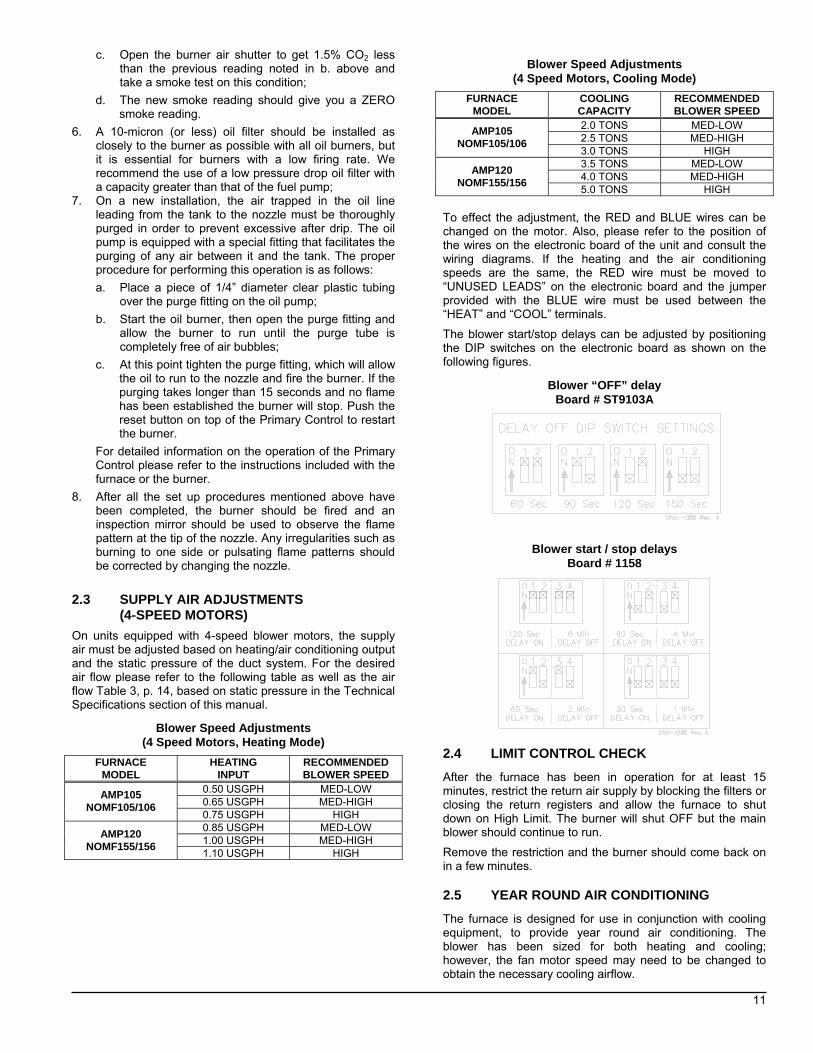
The blower start/stop delays can be adjusted by positioning the DIP switches on the electronic board as shown on the following figures.
Blower “OFF” delay Board # ST9103A
Blower start / stop delays Board # 1158
2.4 LIMIT CONTROL CHECK After the furnace has been in operation for at least 15 minutes, restrict the return air supply by blocking the filters or closing the return registers and allow the furnace to shut down on High Limit. The burner will shut OFF but the main blower should continue to run.
Remove the restriction and the burner should come back on in a few minutes. 2.5 YEAR ROUND AIR CONDITIONING The furnace is designed for use in conjunction with cooling equipment, to provide year round air conditioning. The blower has been sized for both heating and cooling; however, the fan motor speed may need to be changed to obtain the necessary cooling airflow.
12
2.6 HEATING The blower speed is factory set to deliver the required airflow at normal duct static pressure. 2.7 COOLING The blower speed may be adjusted in the field to deliver the required airflow for cooling applications, as outlined in Table 3, p. 14.
2.8 CONSTANT BLOWER SWITCH This furnace is equipped with a constant low speed blower option. Whenever the room thermostat is not calling for heating or cooling, the blower will run on low speed in order to provide air circulation. If this constant blower option is not desired, the rocker switch on the side of the control box can be used to turn it off.
PART 3
MAINTENANCE
This furnace should never be operated without an air filter. Disposable filters should be replaced at least once a year. If the furnace is equipped to provide cooling as well, filters should be replaced a minimum of twice a year.
WARNING Before performing any service functions, make sure that all utilities are turned “OFF” upstream from the appliance, unless operations specifically require the power to be on. Failure to comply with this warning will cause a fire hazard and/or bodily harm. For optimal performance, the oil burner nozzle should be replaced at least once a year. Contact a qualified service technician for the installation. The procedure for nozzle installation and/or replacement is outlined in the oil burner Instruction Manual that was supplied with the furnace. After replacement of the nozzle, the burner should be adjusted in accordance with the “COMBUSTION CHECK” outlined in Section 2.2 of this manual. 3.1 HEAT EXCHANGER CLEANING Ordinarily, it is not necessary to clean the heat exchanger or flue pipe every year, but it is advisable to have a qualified service technician check the unit before each heating season to determine whether cleaning or replacement of parts is necessary. If cleaning is necessary, the following steps should be taken: 1. Turn “OFF” all utilities upstream from the furnace; 2. Disconnect the flue pipe (only with chimney venting and
rigid flue pipe); 3. Remove the breech plate; 4. Remove the radiator baffle; 5. Disconnect the oil line and remove the oil burner from
the furnace;
6. Open the two cleanout doors located in the upper part of the front panel of the furnace;
7. Clean the secondary tubes and the primary cylinder with a stiff brush and a vacuum cleaner;
8. Before reassembly, the heat exchanger and combustion chamber should be inspected to determine if replacement is required;
9. After cleaning, replace the radiator baffle, flue collar plate, oil burner and close the two clean out access doors. Reconnect the flue pipe and oil line;
10. Readjust burner for proper operation. 3.2 BLOWER REMOVAL
To remove the blower from the furnace: 1. Turn “OFF” all utilities upstream from the furnace; 2. Remove the burner access door and blower door; 3. Remove the blower retaining screw (on the blower
partition panel); 4. Remove the control box cover and disconnect the
thermostat and power wires from the board; 5. Slide the blower on the rails toward the front of the unit; 6. Reverse the above steps to reinstall the blower. Please
refer to the wiring diagrams, Figures 8.1 to 8.2, p. 17 & 18 in this manual, or the diagram located on the inside of the blower door to properly rewire the unit.
CAUTION Be sure that the blower is adequately supported when sliding it off the mounting rails, especially in the horizontal or counter flow positions, in order to prevent dropping it and injuring yourself or damaging the blower! 3.3 BLOCKED VENT SHUT OFF (BVSO)
CLEANING For continuous safe operation, the Blocked Vent Shut-off Device (BVSO) must be inspected and maintained annually by a qualified service technician. 1. Disconnect power to the appliance; 2. Remove the two screws holding on the BVSO assembly
cover; 3. Remove the cover;
13
4. Remove the two screws holding the control box to the heat transfer tube assembly. Sliding the control box in the appropriate direction will unlock it from the heat transfer tube assembly;
5. Carefully remove any build-up from the thermal switch surface;
CAUTION Do not dent or scratch the surface of the thermal switch. If the thermal switch is damaged it MUST be replaced.
6. Clean and remove any build-up or obstruction inside the heat transfer tube;
7. Re-mount, lock and fasten the control box with the 2 screws removed in step 4;
8. Re-attach the assembly cover with the screws removed in step 2;
9. Re-establish power to the unit.
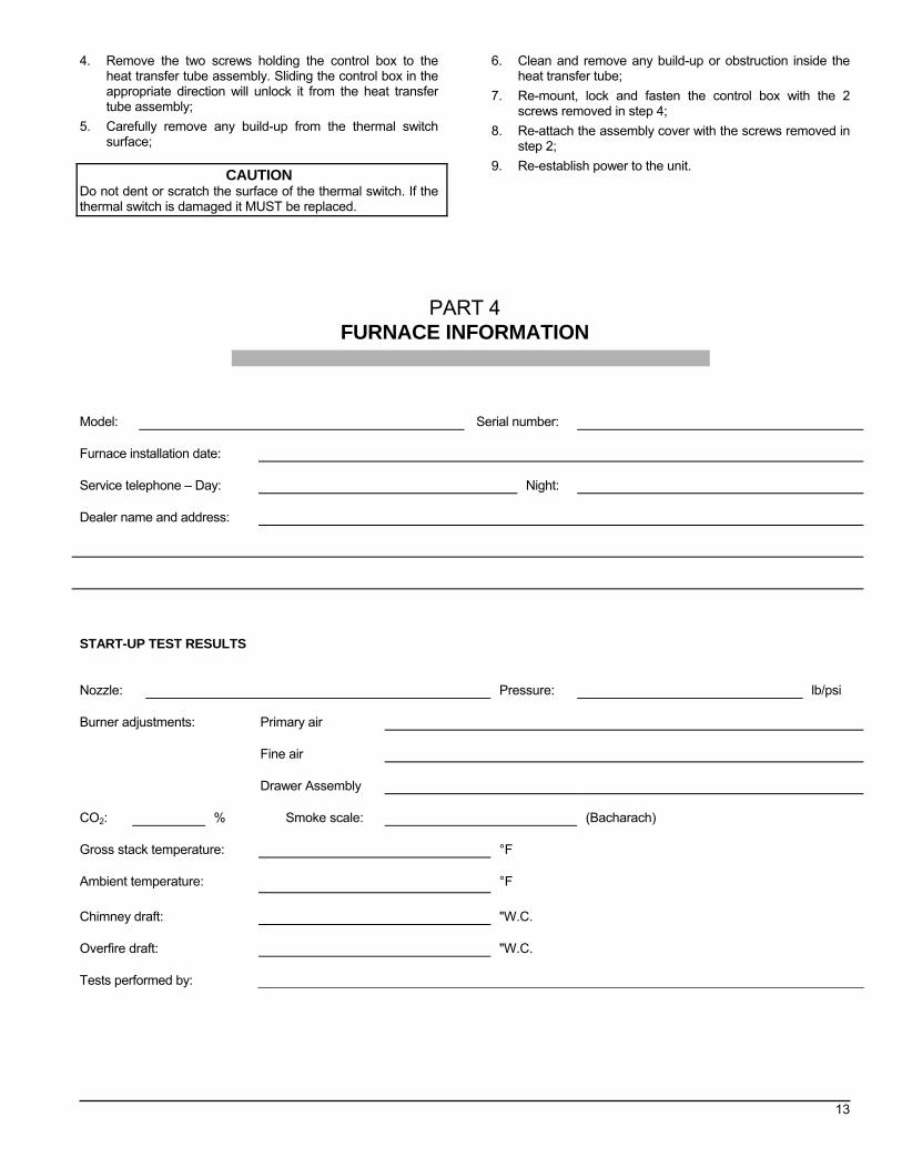
PART 4 FURNACE INFORMATION
Model:
Serial number:
Furnace installation date:
Service telephone – Day:
Night:
Dealer name and address:
START-UP TEST RESULTS
Nozzle:
Pressure:
lb/psi
Burner adjustments:
Primary air
Fine air
Drawer Assembly
CO2:
% Smoke scale:
(Bacharach)
Gross stack temperature:
°F
Ambient temperature:
°F
Chimney draft:
"W.C.
Overfire draft:
"W.C.
Tests performed by:
14
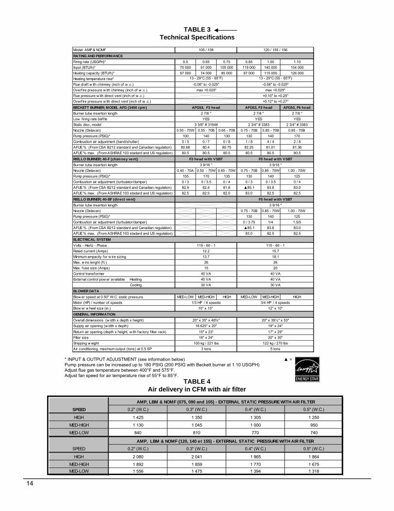
TABLE 3Technical Specifications
TABLE 4Air delivery in CFM with air filter
AMP, LBM & NOMF (075, 090 and 105) - EXTERNAL STATIC PRESSURE WITH AIR FILTERSPEED 0.2" (W.C.) 0.3" (W.C.) 0.4" (W.C.) 0.5" (W.C.)
HIGH 1 425 1 350 1 305 1 250
MED-HIGH 1 130 1 045 1 000 950
MED-LOW 840 810 770 740
AMP, LBM & NOMF (120, 140 et 155) - EXTERNAL STATIC PRESSURE WITH AIR FILTER SPEED 0.2" (W.C.) 0.3" (W.C.) 0.4" (W.C.) 0.5" (W.C.)
Firing rate (USGPH)* 0.5 0.65 0.75 0.85 1.00 1.10Input (BTU/h)* 70 000 91 000 105 000 119 000 140 000 154 000Heating capacity (BTU/h)* 57 000 74 000 85 000 97 000 115 000 126 000Heating temperature rise*Flue draft w ith chimney (inch of w .c.)Overf ire pressure w ith chimney (inch of w .c.)Flue pressure w ith direct vent (inch of w .c.)Overf ire pressure w ith direct vent (inch of w .c.)
RIELLO BURNER; 40-BF (direct vent)Burner tube insertion lengthNozzle (Delavan) 0.75 - 70B 0.85 - 70W 1.00 - 70W Pump pressure (PSIG)* 130 140 125Combustion air adjustment (turbulator/damper) 0 / 3.75 1/4 1.5/5AFUE % (From CSA B212 standard and Canadian regulation) ▲85.1 83.8 83.0AFUE % max. (From ASHRAE 103 stadard and US regulation) 83.0 82.5 82.5
Volts - Hertz - PhaseRated current (Amps)Minimum ampacity for w ire sizingMax. w ire lenght (ft.)Max. fuse size (Amps)Control transformerExternal control pow er available Heating Cooling
Blow er speed at 0.50" W.C. static pressure MED-LOW MED-HIGH HIGH MED-LOW MED-HIGH HIGHMotor (HP) / number of speeds 3/4 HP / 4 speedsBlow er w heel size (in.)
Overall dimensions (w idth x depth x height)Supply air opening (w idth x depth)Return air opening (depth x height, w ith factory f ilter rack)Filter sizeShipping w eightAir conditioning, maximum output (tons) at 0.5 SP
RATING AND PERFORMANCE
13 - 29°C (55 - 85°F) 13 - 29°C (55 - 85°F)
-0.06" to -0.025" -0.06" to -0.025"
AFG53, F3 head
max +0.025" max +0.025"+0.10" to +0.25"
F5 head w ith VSBT
YES YES3 3/8" # 31646 2 3/4" # 3383
ELECTRICAL SYSTEM115 - 60 - 1 115 - 60 - 1
12.2 15.713.7 18.126 2615 20
40 VA 40 VA40 VA 40 VA30 VA 30 VA
BLOWER DATA
1/3 HP / 4 speeds10" x 10" 12" x 10"
16" x 24" 20" x 30"
GENERAL INFORMATION20" x 35" x 48¾" 20" x 39½" x 53"
18.625" x 20" 19" x 24"
2 7/8 '' 2 7/8 ''
3 9/16 ''
105 / 106 120 / 155 / 156
F3 head with VSBT F5 head with VSBT
+0.12" to +0.27"
AFG53, F3 head
3 9/16 ''
3 9/16 ''
100 kg / 221 lbs 122 kg / 270 lbs3 tons 5 tons
15" x 23" 17" x 29"
* INPUT & OUTPUT ADJUSTMENT (see information below) ▲ = Pump pressure can be increased up to 180 PSIG (200 PSIG with Beckett burner at 1.10 USGPH) Adjust flue gas temperature between 400°F and 575°F. Adjust fan speed for air temperature rise of 55°F to 85°F.
15
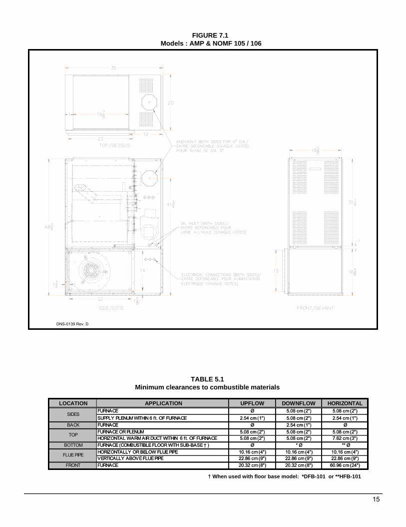
LOCATION APPLICATION UPFLOW DOWNFLOW HORIZONTALFURNACE Ø 5.08 cm (2") 5.08 cm (2")SUPPLY PLENUM WITHIN 6 ft. OF FURNACE 2.54 cm (1") 5.08 cm (2") 2.54 cm (1")
BACK FURNACE Ø 2.54 cm (1") ØFURNACE OR PLENUM 5.08 cm (2") 5.08 cm (2") 5.08 cm (2")HORIZONTAL WARM AIR DUCT WITHIN 6 f t. OF FURNACE 5.08 cm (2") 5.08 cm (2") 7.62 cm (3")
BOTTOM FURNACE (COMBUSTIBLE FLOOR WITH SUB-BASE † ) Ø * Ø ** ØHORIZONTALLY OR BELOW FLUE PIPE 10.16 cm (4") 10.16 cm (4") 10.16 cm (4")VERTICALLY ABOVE FLUE PIPE 22.86 cm (9") 22.86 cm (9") 22.86 cm (9")
FRONT FURNACE 20.32 cm (8") 20.32 cm (8") 60.96 cm (24")
SIDES
TOP
FLUE PIPE
FIGURE 7.1Models : AMP & NOMF 105 / 106
TABLE 5.1Minimum clearances to combustible materials
DNS-0139 Rev. D
† When used with floor base model: *DFB-101 or **HFB-101
LOCATION APPLICATION UPFLOW DOWNFLOW HORIZONTALFURNACE Ø 5.08 cm (2") 5.08 cm (2")SUPPLY PLENUM WITHIN 6 ft. OF FURNACE 2.54 cm (1") 5.08 cm (2") 2.54 cm (1")
BACK FURNACE Ø 2.54 cm (1") ØFURNACE OR PLENUM 5.08 cm (2") 5.08 cm (2") 5.08 cm (2")HORIZONTAL WARM AIR DUCT WITHIN 6 ft. OF FURNACE 5.08 cm (2") 5.08 cm (2") 7.62 cm (3")
BOTTOM FURNACE (COMBUSTIBLE FLOOR WITH SUB-BASE † ) Ø * Ø ** ØHORIZONTALLY OR BELOW FLUE PIPE 10.16 cm (4") 10.16 cm (4") 10.16 cm (4")VERTICALLY ABOVE FLUE PIPE 22.86 cm (9") 22.86 cm (9") 22.86 cm (9")
FRONT FURNACE 20.32 cm (8") 20.32 cm (8") 60.96 cm (24")
SIDES
TOP
FLUE PIPE
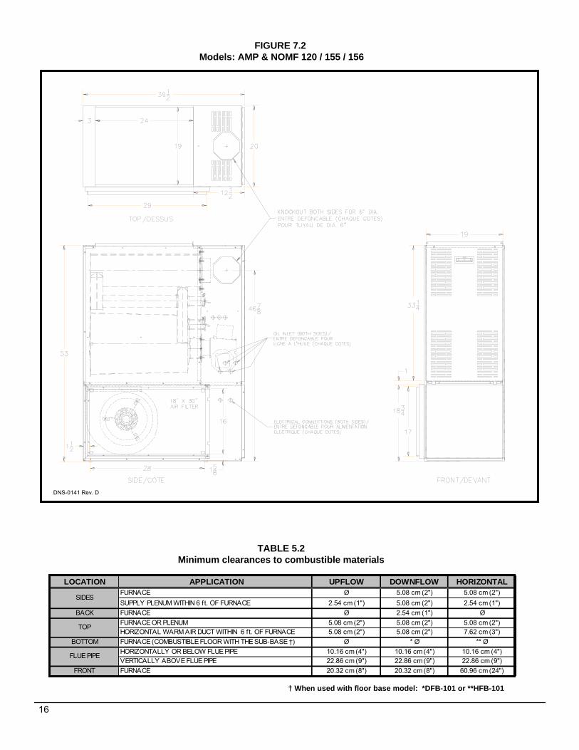
LOCATION APPLICATION UPFLOW DOWNFLOW HORIZONTALFURNACE Ø 5.08 cm (2") 5.08 cm (2")SUPPLY PLENUM WITHIN 6 ft. OF FURNACE 2.54 cm (1") 5.08 cm (2") 2.54 cm (1")
BACK FURNACE Ø 2.54 cm (1") ØFURNACE OR PLENUM 5.08 cm (2") 5.08 cm (2") 5.08 cm (2")HORIZONTAL WARM AIR DUCT WITHIN 6 ft. OF FURNACE 5.08 cm (2") 5.08 cm (2") 7.62 cm (3")
BOTTOM FURNACE (COMBUSTIBLE FLOOR WITH THE SUB-BASE †) Ø * Ø ** ØHORIZONTALLY OR BELOW FLUE PIPE 10.16 cm (4") 10.16 cm (4") 10.16 cm (4")VERTICALLY ABOVE FLUE PIPE 22.86 cm (9") 22.86 cm (9") 22.86 cm (9")
FRONT FURNACE 20.32 cm (8") 20.32 cm (8") 60.96 cm (24")
SIDES
TOP
FLUE PIPE
FIGURE 7.2Models: AMP & NOMF 120 / 155 / 156
TABLE 5.2Minimum clearances to combustible materials
DNS-0141 Rev. D
† When used with floor base model: *DFB-101 or **HFB-101
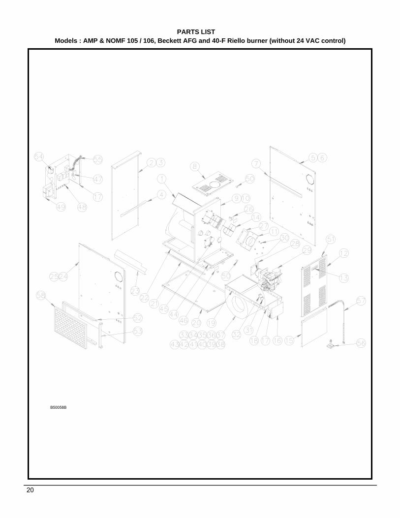
Item Part Description Comments1 B01787 HEAT EXCHANGER ASSEMBLY BAFFLE AND GASKETS NOT INCLUDED2 B01988 REAR BAFFLE3 B01877 REAR PANEL ASSEMBLY INCLUDES PANEL, INSULATION ANS BAFFLE4 B01526-25 INSULATION5 B01874 FRONT TOP PANEL ASSEMBLY INCLUDES PANEL AND LATCH6 B01800-01 SIDE PANEL INSULATION7 B01875-01 RIGHT SIDE PANEL ASSEMBLY INCLUDES PANEL, INSULATION ANS BAFFLE8 B01805-01 RIGHT SIDE BAFFLER9 Z99F003 LATCHE ASSEMBLY, FEMALE
10 B01878 FRONT DIVIDER PANEL ASSEMBLY INCLUDES PANEL, INSULATION AND BABELS11 B01853 FRONT SEPARATOR INSULATION12 R02R005 HIGH LIMIT 175-20F 1 3/4"13 B03598 SOUND TRAP ASSEMBLY INCLUDES BAFFLE AND INSULATION14 B00205 GASKET, FLUE OUTLET FLANGE 15 B01747 FLUE OUTLET FLANGE 6" DIA. 16 F07O001 HEX FLANGE NUT 3/8-16NC LAITON17 F07F011 HEX NUT 3/8-16NC ZINC 18 N04Z064 GASKET BURNER FLANGE19 N01F045 BURNER RIELLO 40-F520 Z99F038 LATCHE, MALE21 B01852 FRONT DOOR DOOR ONLY22 Z99F050 RECESSED HANDLE, BLACK 23 B03341-01 BVSO ELECTRICAL KIT24 Z06G001 BLOCKED VENT SHUT-OFF BVSO-22525 B01873-05 BLOWER DOOR ASSEMBLY INCLUDES DOOR AND LABEL26 B01684 ELECTRICAL BOX COVER27 B03720-05 BLOWER 120-10T INCLUDES WHEEL AND HOUSING28 L06I004 MOTOR 3/4 DD 4S 29 B01889 MOTOR SUPPORT ASSEMBLY INCLUDES LEGS, BAND AND FASTENERS30 B00202 ELECTRICAL WIRE HARNESS (BLOWER)31 B01024 CAPACITOR HOLDER32 L01I005 CAPACITOR 15 MF33 B03319 ELECTRICAL KIT, RIELLO34 L07F003 ROCKER SWITCH SPST35 R99G004 ELECTRONIC BOARD 1158-11036 B01683 ELECTRICAL BOX37 L01F009 TRANSFORMER 120-24Volts, 40VA 38 B01682 ELECTRICAL BOX BRAQUET39 B01681 BLOWER SLIDE RAIL 2 REQUIRED40 B01291-01 SEAL STRIP 1 1/2" X 13 1/8"41 B01406-01 REPLACEMENT BLOWER ASSEMBLY INCLUDES BLOWER, MOTOR AND CAPACITOR42 B01804 FLOOR43 A00284 HIGH LIMIT PROTECTIVE SHIELD44 R02R002 LIMIT CONTROL 140F, 7" 45 B02111 OBSERVATION DOOR ASSEMBLY46 B01794 BLOWER SLIDE SUPPORT 2 REQUIRED47 B01795 BLOWER DIVIDER PANEL ONLY48 B01805-02 LEFT SIDE BAFFLE49 B01875-02 LEFT SIDE PANEL ASSEMBLY INCLUDES PANEL, INSULATION AND BAFFLE50 B01800-02 SIDE PANEL INSULATION51 B01809 FILTER RACK FRAME52 B01808 FILTER RACK ACCESS53 Z04F013 PAPER FILTER 20 X 30 X 1
PARTS LISTModel : AMP120, Riello 40-BF burner
B50078B
26
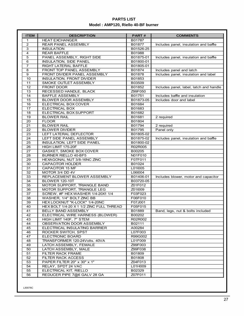
PARTS LISTModel : AMP120, Riello 40-BF burner
L50078C
27
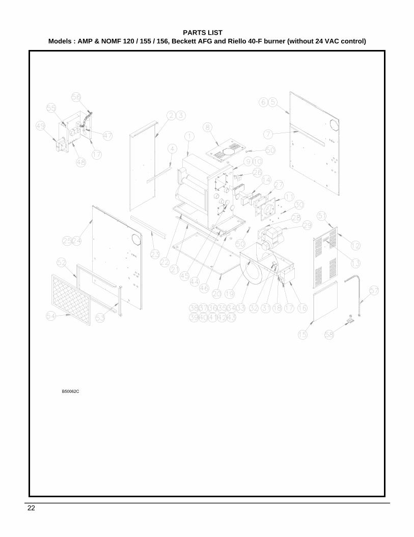
ITEM DESCRIPTION PART # COMMENTS1 HEAT EXCHANGER B017872 REAR PANEL ASSEMBLY B01877 Includes panel, insulation and baffle3 INSULATION B01526-254 REAR BAFFLE B019885 PANEL ASSEMBLY, RIGHT SIDE B01875-01 Includes panel, insulation and baffle6 INSULATION, SIDE PANEL B01800-017 RIGHT LATERAL BAFFLE B01805-018 FRONT TOP PANEL ASSEMBLY B01874 Includes panel and latch9 FRONT DIVIDER PANEL ASSEMBLY B01878 Includes panel, insulation and label10 INSULATION, FRONT DIVIDER B0185311 SMOKE OUTLET ASSEMBLY B0350912 FRONT DOOR B01852 Includes panel, label, latch and handle13 RECESSED HANDLE, BLACK Z99F05014 BAFFLE ASSEMBLY B01751 Includes baffle and insulation15 BLOWER DOOR ASSEMBLY B01873-05 Includes door and label16 ELECTRICAL BOX COVER B0168417 ELECTRICAL BOX B0168318 ELECTRICAL BOX SUPPORT B0168219 BLOWER RAIL B01681 2 required20 FLOOR B0180421 BLOWER RAIL B01794 2 required22 BLOWER DIVIDER B01795 Panel only23 LEFT LATERAL DEFLECTOR B01805-0224 LEFT SIDE PANEL ASSEMBLY B01875-02 Includes panel, insulation and baffle25 INSULATION, LEFT SIDE PANEL B01800-0226 HIGH LIMIT 175-20F R02R00527 GASKET, SMOKE BOX COVER B0020528 BURNER RIELLO 40-BF5 N01F01029 HEXAGONAL NUT 3/8-16NC ZINC F07F01130 CAPACITOR HOLDER B0102431 CAPACITOR 15 MF L01I00532 MOTOR 3/4 DD 4V L06I00433 REPLACEMENT BLOWER ASSEMBLY B01406-01 Includes blower, motor and capacitor34 BLOWER 120-10T B03720-0535 MOTOR SUPPORT, TRIANGLE BAND Z01F01236 MOTOR SUPPORT, TRIANGLE LEG Z01I00937 SCREW, #F HEX WASHER 1/4-20X1 1/4 F03F02338 WASHER, 1/4" BOLT ZINC BB F06F01039 HEX LOCKNUT "K-LOCK" 1/4-20NC F07J00140 HEX BOLT 1/4-20 X 1 1/2 ZINC FULL THREAD F05F01541 BELLY BAND ASSEMBLY B01889 Band, legs, nut & bolts included42 ELECTRICAL WIRE HARNESS (BLOWER) B0020243 HIGH LIMIT 140F, 7" STEM R02R00244 OBSERVATION DOOR ASSEMBLY B0211145 ELECTRICAL INSULATING BARRIER A0028446 ROCKER SWITCH, SPST L07F00347 ELECTRONIC BOARD R99G00248 TRANSFORMER 120-24Volts, 40VA L01F00949 LATCH ASSEMBLY, FEMALE Z99F00350 LATCH ASSEMBLY, MALE Z99F03851 FILTER RACK FRAME B0180952 FILTER RACK ACCESS B0180853 PAPER FILTER 20" x 30" x 1" Z04F01354 RELAY, SPDT 24 VAC L01H00955 ELECTRICAL KIT, RIELLO B0232956 REDUCER PIPE 7@6 GALV 28 GA Z07F011