11
Furnace Camera System Operator’s Manual Version 12-2010
Furnace Camera System
Operator’s Manual
Version 12-2010

Logika Technologies Inc. Model FCS Operator’s Manual Rev. 12-2010
Web: www.logikatech.com Phone: 905-829-5841 Fax: 905-829-8787 Email: [email protected]
P a g e | 1
Contents
1. Introduction ....................................................................................................................... 2
2. Description ....................................................................................................................... 2
2.1 Model Nomenclature ................................................................................................... 2
2.2 Specifications .............................................................................................................. 3
2.3 Confirmation of Camera Field of View ....................................................................... 4
3. Location and Mounting ..................................................................................................... 5
3.1 Sensor Location ......................................................................................................... 5
3.2 Installation and Mounting Notes ................................................................................. 6
3.2 Sensor Mounting ......................................................................................................... 6
4. Operation ......................................................................................................................... 7
4.1 Controls....................................................................................................................... 7
5. Maintenance ..................................................................................................................... 8
5.1 Regular Maintenance .................................................................................................. 8
5.2 Returns of the FCS ...................................................................................................... 8
6. FCS Junction Box Layouts ............................................................................................... 9

Logika Technologies Inc. Model FCS Operator’s Manual Rev. 12-2010
Web: www.logikatech.com Phone: 905-829-5841 Fax: 905-829-8787 Email: [email protected]
P a g e | 2
1. Introduction
The Logika Technologies Furnace Camera System, is designed for use in steel, aluminum and
other metal mill production lines, allowing operators to observe materials in furnaces. It can
also be used to monitor combustion in power and boiler operations. It includes a rugged
enclosure protecting a high resolution camera and will withstand the harsh ambient conditions
present in heavy industrial environments.
The Unit includes water cooling and air purge to enable the camera to work in the hostile
environments around industrial furnaces. Temperature sensors and an Automatic Retraction
System provide insurance against overheating and the local electrical and pneumatic panels
simplify installation.
Applications include:
� Steel – Blast, Melt and reheat Furnaces
� Cement – Clinker Cooler, Rotary Kiln
� Power Generation – Combustion Monitoring
� Glass – Float Glass Line
� Waste Combustion – Grate Firing
� Clay and Ceramics – Kiln Monitoring
2. Description
2.1 Model Nomenclature
Record your Furnace Camera System’s complete Model Number here:
FCS - ___________ - __________
Base Model Power Input Mount Angle Wall Thickness
FCS 110: 110 VAC Customer
Furnace
Dependent
Customer
Furnace
Dependent
220: 220 VAC
Serial Number _________________

Logika Technologies Inc. Model FCS Operator’s Manual Rev. 12-2010
Web: www.logikatech.com Phone: 905-829-5841 Fax: 905-829-8787 Email: [email protected]
P a g e | 3
2.2 Specifications
Operating Temp Temperature inside the furnace ≤ 2000oC
Auto-exit device ≤ 90oC, control system ≤ 70
oC
Air Supply Compressed air, inlet pipe diameter G 1/2”, pipeline diameter G 3/4”
Power Input 110VAC 60Hz, 220V 50 Hz <120W
Output Hi resolution NTSC color composite signal
Compressed Air Pressure 0.1-0.7 MPa (15 to 100 psi) depending on the temperature inside
furnace
Flow: 0.1-0.4 m3/min (3.5 to 14 cfm)
Inlet temperature of compressed air ≤35oC (95
oF)
Lens Special high-temperature resistant pinhole lens
Image Index Resolution ≥ 650 lines (976 x 572 pixels), Signal-to-noise ≥ 42 dB
Visual angle (diagonal line) 80 o
diagonal, Image Sensor 1/3”
Signal to Noise Ratio >50 dB, sensitivity 0.1 lux
Auto Retract The probe will automatically retract from Furnace Chamber at over-
temperature, regardless of pneumatic loss (add UPS to cover electrical power
loss as well)
Weight Auto-exit device about30 kg; furnace wall cover about 30 kg
Dimensions Auto-exit device 1280 (L) × 320 (W) × 480 (H) mm (50”L x 12.6W” x 19”H)
Furnace Hole ø 140 mm, 120o horn-like hole on interior wall of furnace

Logika Technologies Inc. Model FCS Operator’s Manual Rev. 12-2010
Web: www.logikatech.com Phone: 905-829-5841 Fax: 905-829-8787 Email: [email protected]
P a g e | 4
2.3 Confirmation of Camera Field of View
Calculation Formula for Field of View:
Where:
f= (focal length of pinhole lens) = 3.5 mm
H = (height of field of view) (m)
W = (width of field of view) (m)
L = (the distance between the lens and target) (m)
h = (1/3” height of camera sensor) = 3.6 mm
w = (1/3” width of camera sensor) = 4.8 mm
L(m) 3.5 4 4.5 5 6 7 8 9 10
H (m) 3.6 4.1 4.6 5.1 6.2 7.2 8.2 9.3 10.3
W (m) 4.8 5.5 6.2 6.9 8.2 9.6 11.0 12.3 13.7
Logika Technologies Inc. Model FCS Operator’s Manual Rev. 12-2010
Web: www.logikatech.com Phone: 905-829-5841 Fax: 905-829-8787 Email: [email protected]
P a g e | 5
3. Location and Mounting
3.1 Sensor Location
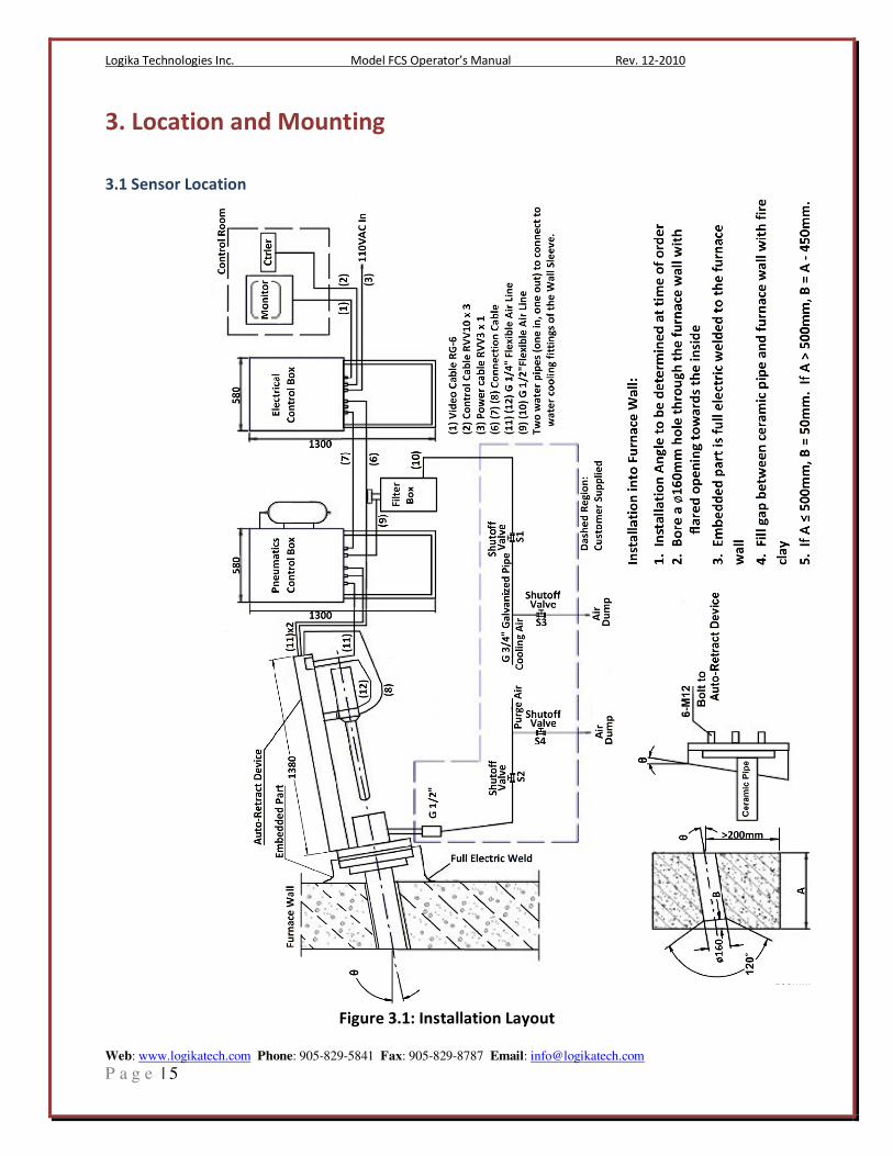
Figure 3.1: Installation Layout

Logika Technologies Inc. Model FCS Operator’s Manual Rev. 12-2010
Web: www.logikatech.com Phone: 905-829-5841 Fax: 905-829-8787 Email: [email protected]
P a g e | 6
In order to maximize the proportion of the monitored target in the monitoring image, it is
suggested to bore the hole on the furnace wall as near to the monitored target as possible.
3.2 Installation and Mounting Notes
1. The pitch angle should be confirmed on ordering.
2. After the equipment is installed for the air supply to the furnace door, the user should tie in
G 1/2” pipe for laying to the FCS. The air inlet to the filtration tank should be 0.5 m away
from the filtration tank and G1/2” outer thread is remained.
3. The standard distance between the pneumatic control box and auto-retract device is 2 m;
additional pipe is necessary if the distance is greater.
4. The pipeline inside the dashed frame in Figure 3.1 is to be provided by the customer.
5. Bore 140 mm hole in furnace wall, with a flared opening toward the interior.
6. The embedded parts should be welded and fixed to the outer skin (steel plate) of the furnace
wall and full welding is required. The ceramic pipe and the hole gap on the furnace wall
should be filled with fire clay.
7. For proper installation and operation of this equipment, a 500 mm clearance radius around
the center of the bored hole is required
8. Bolt or weld the Electric and Pneumatic Control Panels solidly into place close to the Auto-
Retract Device but out of the way for maintenance operations.
9. Required Air Pressure: 0.1-0.7MPa
10. Required Air Flow: 0.1-0.4 m3/min
11. Required Air Temperature: ≤ 35oC
12. Temperature inside the furnace: ≤ 2000oC
13. Air source: compressed air
14. From Figure 3.1: Cables (1), (2), (3), (4) should be provided by the customer.
(1) Video cable SYV 75-5 (RG-6)
(2) Control cable RVV 10×0.5
(3) (4) power cable RVV 3×1
(5), (8), (9) are the (included) cross-over pipes of the equipment with G 1/4” fittings.
(6), (7) are the (included) connecting cables of the equipment.
15. The customer installs G 1/2” rigid pipe for the cooling water to within 0.5 m of the
embedded parts, terminated with a shutoff with G 1/2” male fitting. Similarly, the
customer installs G 1/2” rigid pipe for the cooling water return to within 0.5 m of the
embedded parts, terminated with a shutoff with G 1/2” male fitting.
16. Before the air is applied to the equipment, close shutoff valves S1 and S2, open S3 and S4
for ventilation. After the pipes have been completely blown out, close S3, S4 and open S1,
S2. The equipment is then ready for normal operation.
3.2 Sensor Mounting
Logika Technologies Inc. Model FCS Operator’s Manual Rev. 12-2010
Web: www.logikatech.com Phone: 905-829-5841 Fax: 905-829-8787 Email: [email protected]
P a g e | 7
4. Operation
4.1 Controls
The Control Box will be located with the monitor in the Control Room. It will allow the operator
to retract or insert the camera probe at will.

Logika Technologies Inc. Model FCS Operator’s Manual Rev. 12-2010
Web: www.logikatech.com Phone: 905-829-5841 Fax: 905-829-8787 Email: [email protected]
P a g e | 8
5. Maintenance
5.1 Regular Maintenance
� Diagnostics- Normally, the FCS does not require maintenance at a fixed period. Regular
attention to the following will ensure steady operation of the sensor:
� Lens Cleaning- Routinely check the FCS sensor’s pinhole lens for dust or oil residue. Open the
lens shield at the front of the sensor by unscrewing the fastening hardware on the shield and
clean the lens with alcohol and lens paper or lint-free cloth.
� Detector- The pneumatic filters should be inspected and replaced as necessary according to the
plant maintenance schedule.
5.2 Returns of the FCS
� Contact us with the Serial Number of your sensor before you return our product. If we are
unable to solve the problem by phone or email, we will then provide you with a return
authorization number.
� Do not return the FCS without an authorization number.
� If the product is out of warranty, we will provide a repair estimate and then complete the
repairs after your approval.

Logika Technologies Inc. Model FCS Operator’s Manual Rev. 12-2010
Web: www.logikatech.com Phone: 905-829-5841 Fax: 905-829-8787 Email: [email protected]
P a g e | 9
6. FCS Junction Box Layouts
Figure 6.1: FCS Pneumatic Junction Box Layout

Logika Technologies Inc. Model FCS Operator’s Manual Rev. 12-2010
Web: www.logikatech.com Phone: 905-829-5841 Fax: 905-829-8787 Email: [email protected]
P a g e | 10
Figure 6.2: FCS Electrical Junction Box Layout


