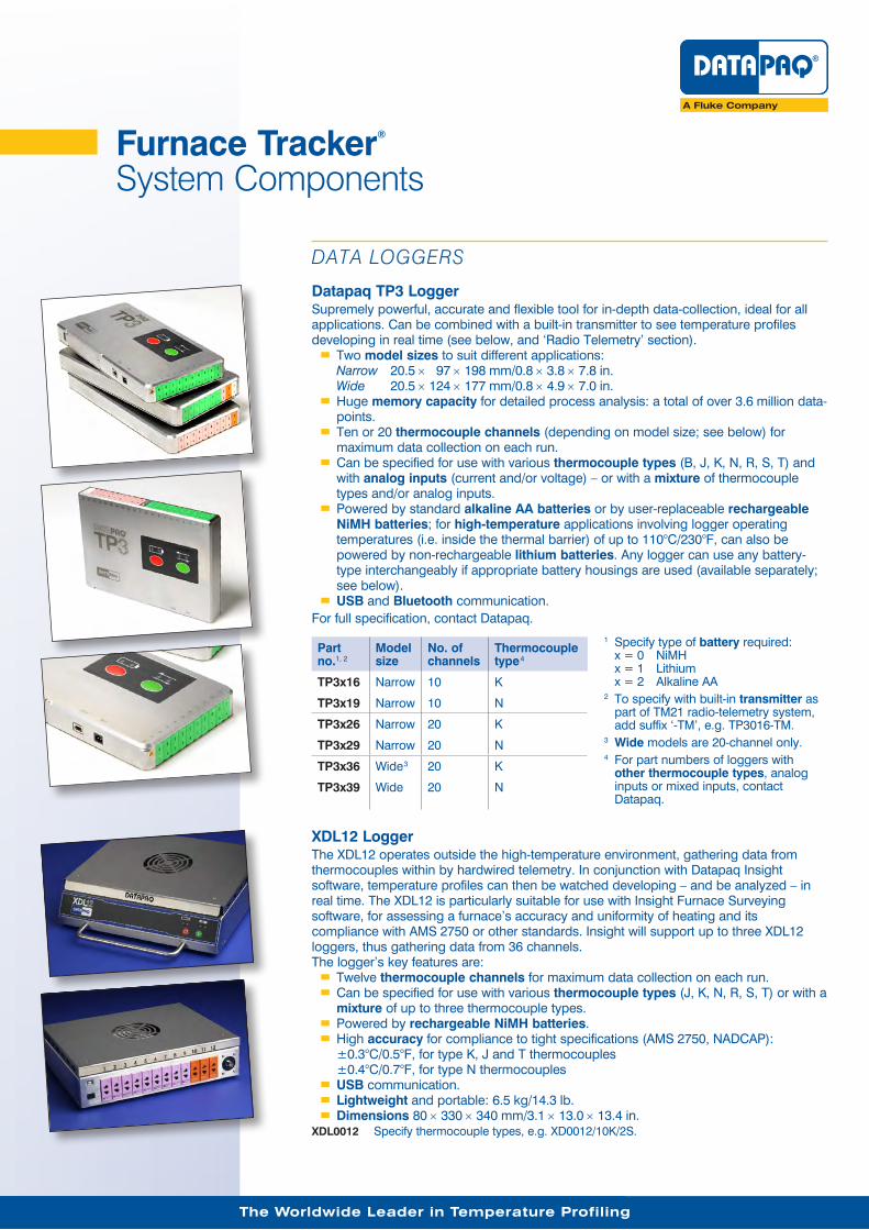
1 Furnace Tracker ® System Components DATA LOGGERS Datapaq TP3 Logger Supremely powerful, accurate and flexible tool for in-depth data-collection, ideal for all applications. Can be combined with a built-in transmitter to see temperature profiles developing in real time (see below, and ‘Radio Telemetry’ section). Two model sizes to suit different applications: Narrow 20.5 × 97 × 198 mm/0.8 × 3.8 × 7.8 in. Wide 20.5 × 124 × 177 mm/0.8 × 4.9 × 7.0 in. Huge memory capacity for detailed process analysis: a total of over 3.6 million data- points. Ten or 20 thermocouple channels (depending on model size; see below) for maximum data collection on each run. Can be specified for use with various thermocouple types (B, J, K, N, R, S, T) and with analog inputs (current and/or voltage) – or with a mixture of thermocouple types and/or analog inputs. Powered by standard alkaline AA batteries or by user-replaceable rechargeable NiMH batteries; for high-temperature applications involving logger operating temperatures (i.e. inside the thermal barrier) of up to 110°C/230°F, can also be powered by non-rechargeable lithium batteries. Any logger can use any battery- type interchangeably if appropriate battery housings are used (available separately; see below). USB and Bluetooth communication. For full specification, contact Datapaq. Part no. 1, 2 Model size No. of channels Thermocouple type 4 1 Specify type of battery required: x = 0 NiMH x = 1 Lithium x = 2 Alkaline AA 2 To specify with built-in transmitter as part of TM21 radio-telemetry system, add suffix ‘-TM’, e.g. TP3016-TM. 3 Wide models are 20-channel only. 4 For part numbers of loggers with other thermocouple types, analog inputs or mixed inputs, contact Datapaq. TP3x16 Narrow 10 K TP3x19 Narrow 10 N TP3x26 Narrow 20 K TP3x29 Narrow 20 N TP3x36 Wide 3 20 K TP3x39 Wide 20 N XDL12 Logger The XDL12 operates outside the high-temperature environment, gathering data from thermocouples within by hardwired telemetry. In conjunction with Datapaq Insight software, temperature profiles can then be watched developing – and be analyzed – in real time. The XDL12 is particularly suitable for use with Insight Furnace Surveying software, for assessing a furnace’s accuracy and uniformity of heating and its compliance with AMS 2750 or other standards. Insight will support up to three XDL12 loggers, thus gathering data from 36 channels. The logger’s key features are: Twelve thermocouple channels for maximum data collection on each run. Can be specified for use with various thermocouple types (J, K, N, R, S, T) or with a mixture of up to three thermocouple types. Powered by rechargeable NiMH batteries. High accuracy for compliance to tight specifications (AMS 2750, NADCAP): ±0.3°C/0.5°F, for type K, J and T thermocouples ±0.4°C/0.7°F, for type N thermocouples USB communication. Lightweight and portable: 6.5 kg/14.3 lb. Dimensions 80 × 330 × 340 mm/3.1 × 13.0 × 13.4 in. XDL0012 Specify thermocouple types, e.g. XD0012/10K/2S. The Worldwide Leader in Temperature Profiling
Transcript
11
Furnace Tracker® System Components
DATA LOGGERS
Datapaq TP3 LoggerSupremely powerful, accurate and flexible tool for in-depth data-collection, ideal for all applications. Can be combined with a built-in transmitter to see temperature profiles developing in real time (see below, and ‘Radio Telemetry’ section).
�� Two model sizes to suit different applications: Narrow 20.5 × 97 × 198 mm/0.8 × 3.8 × 7.8 in. Wide 20.5 × 124 × 177 mm/0.8 × 4.9 × 7.0 in.�� Huge memory capacity for detailed process analysis: a total of over 3.6 million data-points.�� Ten or 20 thermocouple channels (depending on model size; see below) for maximum data collection on each run.�� Can be specified for use with various thermocouple types (B, J, K, N, R, S, T) and with analog inputs (current and/or voltage) – or with a mixture of thermocouple types and/or analog inputs.�� Powered by standard alkaline AA batteries or by user-replaceable rechargeable NiMH batteries; for high-temperature applications involving logger operating temperatures (i.e. inside the thermal barrier) of up to 110°C/230°F, can also be powered by non-rechargeable lithium batteries. Any logger can use any battery-type interchangeably if appropriate battery housings are used (available separately; see below).�� USB and Bluetooth communication.
For full specification, contact Datapaq.
Part no.1, 2
Model size
No. of channels
Thermocouple type4
1 Specify type of battery required: x = 0 NiMH x = 1 Lithium x = 2 Alkaline AA
2 To specify with built-in transmitter as part of TM21 radio-telemetry system, add suffix ‘-TM’, e.g. TP3016-TM.
3 Wide models are 20-channel only.4 For part numbers of loggers with
other thermocouple types, analog inputs or mixed inputs, contact Datapaq.
TP3x16 Narrow 10 K
TP3x19 Narrow 10 N
TP3x26 Narrow 20 K
TP3x29 Narrow 20 N
TP3x36 Wide3 20 K
TP3x39 Wide 20 N
XDL12 LoggerThe XDL12 operates outside the high-temperature environment, gathering data from thermocouples within by hardwired telemetry. In conjunction with Datapaq Insight software, temperature profiles can then be watched developing – and be analyzed – in real time. The XDL12 is particularly suitable for use with Insight Furnace Surveying software, for assessing a furnace’s accuracy and uniformity of heating and its compliance with AMS 2750 or other standards. Insight will support up to three XDL12 loggers, thus gathering data from 36 channels.The logger’s key features are:
�� Twelve thermocouple channels for maximum data collection on each run.�� Can be specified for use with various thermocouple types (J, K, N, R, S, T) or with a mixture of up to three thermocouple types.�� Powered by rechargeable NiMH batteries.�� High accuracy for compliance to tight specifications (AMS 2750, NADCAP): ±0.3°C/0.5°F, for type K, J and T thermocouples ±0.4°C/0.7°F, for type N thermocouples�� USB communication.�� Lightweight and portable: 6.5 kg/14.3 lb.�� Dimensions 80 × 330 × 340 mm/3.1 × 13.0 × 13.4 in.
XDL0012 Specify thermocouple types, e.g. XD0012/10K/2S.
The Worldwide Leader in Temperature Profiling
2
LOGGER CABLES, CHARGER AND BLUETOOTH
CI1150 USB Communications Lead for TP3 LoggerConnects logger to PC to enable logger reset, data download or display of real-time data-collection.
CI3029 70°C Communications Lead for Q18 and Tpaq21 Loggers
CI1033 USB Communications Lead for High-temperature Tpaq21 Logger
For use only with high-ambient-temperature loggers with lithium batteries. No power socket.
CH0070 Charger/Power-supply UnitFor TP3, XDL12, Q18 and Tpaq21 loggers, and TM21 primary receiver.
CI1034 Bluetooth Classic USB AdapterSuitable for use with a PC or laptop which does not have Bluetooth built-in, in order to permit Bluetooth communication with TP3 logger.
LOGGER BATTERIESAny TP3 logger can use any of the three battery-types interchangeably if appropriate battery housings are used. Battery housings are user-replaceable.
NiMH Rechargeable Batteries, for TP3 Logger: Battery Housing and Battery-packNiMH battery-packs are user-replaceable.BP3000 Battery housing plus battery-pack (as in photo).BP3010 Battery housing (does not include batteries).BP3001 Battery-pack (does not include housing).
Alkaline AA Batteries, for TP3 Logger: Battery Housing and Battery-packBP3051 Battery housing plus battery-pack (as in photo).BP3050 Battery housing (does not include batteries).BP0011 Pack of four batteries (does not include housing).
Lithium Batteries, for TP3 Logger: Battery Housing and Battery-packLithium batteries are non-rechargeable and are for high-temperature use. Battery life up to 250 hrs depending on sample interval, operating temperature and use of telemetry. Maximum operating temperature 110°C/230°F. Only lithium batteries supplied by Datapaq are suitable for use with Datapaq loggers. Lithium batteries are potentially dangerous: you must read the relevant section of your logger’s User Manual and the Safety Data Sheet supplied with the batteries.BP3021 Battery housing plus battery-pack (as in photo).BP3100 Battery housing (does not include batteries).BP0021 Pack of four batteries. Also suitable for high-temperature versions of Tpaq21 logger.
Maximum six packs per shipment.
33
www.datapaq.com
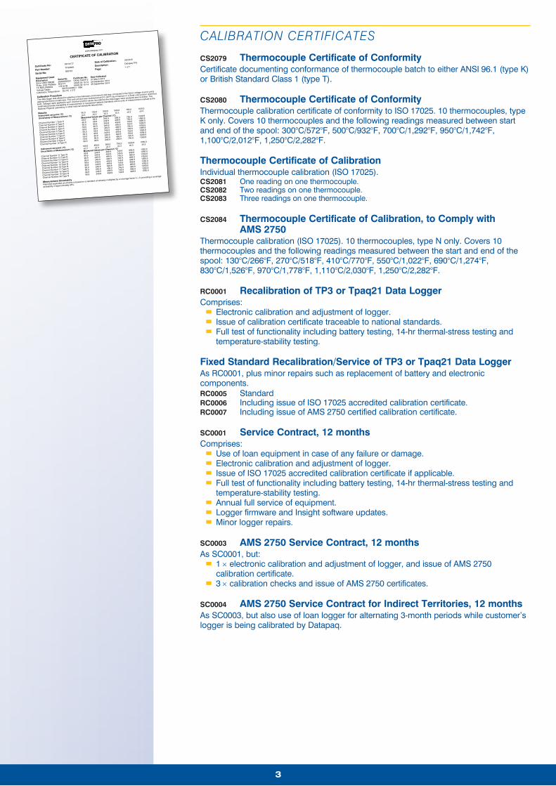
CERTIFICATE OF CALIBRATION
Certificate No:
Part Number:
Serial No:
PR15177
TP3030A
000123
Date of Calibration:
Description:
Page:
3/6/2015
Datapaq TP3
1 of 1
Equipment Used
Description
Xitron 2000 PM268
Fluke 9101 PM366a
TC BOX PM366a
Serial No
20004030001
B16777
17919/1B
Certificate No.
UKAS T401812
UKAS 03-10-14
UKAS 03-10-14
Date Calibrated
31 March 2014
29 September 2014
29 September 2014
Voltage Tables:
Laboratory Temperature:
BS EN 60584-1 1996
25.3°C ± 2°C
Calibration Procedure
The data logger was allowed to stabilise in the laboratory environment and was connected to the Xitron voltage source using
appropriate thermocouple wire. The cold junction was maintained at 0°C (32°F) by immersion in a Zeref cold junction reference
bath. Voltages were applied to each channel and the values recorded by the data logger were analysed and recorded. This
certificate provides traceability of measurement to recognised national standards and to units of measurement realised at the
National Physical Laboratory or other national standards laboratories.
Results
Instrument set point (°C)
Uncertainty of Measurement (°C)Measured Values per Channel (°C)
Channel Number 1 Type K
Channel Number 2 Type K
Channel Number 3 Type K
Channel Number 4 Type K
Channel Number 5 Type K
Channel Number 6 Type K
Channel Number 7 Type K
Channel Number 8 Type K
Channel Number 9 Type K
Channel Number 10 Type K
Instrument set point (°C)
Uncertainty of Measurement (°C)Measured Values per Channel (°C)
Channel Number 11 Type N
Channel Number 12 Type N
Channel Number 13 Type N
Channel Number 14 Type N
Channel Number 15 Type N
Channel Number 16 Type N
Channel Number 17 Type N
Channel Number 18 Type N
Channel Number 19 Type N
Channel Number 20 Type N
-50.0
±0.3
-50.0
-50.0
-50.0
-50.0
-50.0
-50.0
-50.0
-50.0
-50.0
-50.0
100.0
±0.3
99.9
99.9
99.9
99.9
99.9
99.9
99.9
99.9
99.9
99.9
100.0
±0.3
99.9
99.9
99.9
99.9
99.9
99.9
99.9
99.9
99.9
99.9
250.0
±0.3
249.9
249.9
249.9
249.9
249.9
249.9
249.9
249.9
249.9
249.9
250.0
±0.3
249.9
249.9
249.9
249.9
249.9
249.9
249.9
249.9
249.9
249.9
500.0
±0.3
499.9
499.9
499.9
499.9
499.9
499.9
499.9
499.9
499.9
499.9
500.0
±0.3
499.9
499.9
499.9
499.9
499.9
499.9
499.9
499.9
499.9
499.9
750.0
±0.3
749.9
749.9
749.9
749.9
749.9
749.9
749.9
749.9
749.9
749.9
750.0
±0.3
750.0
750.0
750.0
750.0
750.0
750.0
750.0
750.0
750.0
750.0
1000.0
±0.3
999.9
999.9
999.9
999.9
999.9
999.9
999.9
999.9
999.9
999.9
1100.0
±0.3
1099.9
1099.9
1099.9
1099.9
1099.9
1099.9
1099.9
1099.9
1099.9
1099.9
1250.0
±0.3
1250.0
1250.0
1250.0
1250.0
1250.0
1250.0
1250.0
1250.0
1250.0
1250.0
Measurement Uncertainty
Reported expanded uncertainty is based on a standard uncertainty multiplied by a coverage factor k = 2, providing a coverage
probability of approximately 95%.
www.datapaq.com
CERTIFICATE OF CALIBRATION
Certificate No:
Part Number:
Serial No:
PR15177
TP3030A
000123
Date of Calibration:
Description:
Page:
3/6/2015
Datapaq TP3
1 of 1
Equipment Used
Description
Xitron 2000 PM268
Fluke 9101 PM366a
TC BOX PM366a
Serial No
20004030001
B16777
17919/1B
Certificate No.
UKAS T401812
UKAS 03-10-14
UKAS 03-10-14
Date Calibrated
31 March 2014
29 September 2014
29 September 2014
Voltage Tables:
Laboratory Temperature:
BS EN 60584-1 1996
25.3°C ± 2°C
Calibration Procedure
The data logger was allowed to stabilise in the laboratory environment and was connected to the Xitron voltage source using
appropriate thermocouple wire. The cold junction was maintained at 0°C (32°F) by immersion in a Zeref cold junction reference
bath. Voltages were applied to each channel and the values recorded by the data logger were analysed and recorded. This
certificate provides traceability of measurement to recognised national standards and to units of measurement realised at the
National Physical Laboratory or other national standards laboratories.
Results
Instrument set point (°C)
Uncertainty of Measurement (°C)Measured Values per Channel (°C)
Channel Number 1 Type K
Channel Number 2 Type K
Channel Number 3 Type K
Channel Number 4 Type K
Channel Number 5 Type K
Channel Number 6 Type K
Channel Number 7 Type K
Channel Number 8 Type K
Channel Number 9 Type K
Channel Number 10 Type K
Instrument set point (°C)
Uncertainty of Measurement (°C)Measured Values per Channel (°C)
Channel Number 11 Type N
Channel Number 12 Type N
Channel Number 13 Type N
Channel Number 14 Type N
Channel Number 15 Type N
Channel Number 16 Type N
Channel Number 17 Type N
Channel Number 18 Type N
Channel Number 19 Type N
Channel Number 20 Type N
-50.0
±0.3
-50.0
-50.0
-50.0
-50.0
-50.0
-50.0
-50.0
-50.0
-50.0
-50.0
100.0
±0.3
99.9
99.9
99.9
99.9
99.9
99.9
99.9
99.9
99.9
99.9
100.0
±0.3
99.9
99.9
99.9
99.9
99.9
99.9
99.9
99.9
99.9
99.9
250.0
±0.3
249.9
249.9
249.9
249.9
249.9
249.9
249.9
249.9
249.9
249.9
250.0
±0.3
249.9
249.9
249.9
249.9
249.9
249.9
249.9
249.9
249.9
249.9
500.0
±0.3
499.9
499.9
499.9
499.9
499.9
499.9
499.9
499.9
499.9
499.9
500.0
±0.3
499.9
499.9
499.9
499.9
499.9
499.9
499.9
499.9
499.9
499.9
750.0
±0.3
749.9
749.9
749.9
749.9
749.9
749.9
749.9
749.9
749.9
749.9
750.0
±0.3
750.0
750.0
750.0
750.0
750.0
750.0
750.0
750.0
750.0
750.0
1000.0
±0.3
999.9
999.9
999.9
999.9
999.9
999.9
999.9
999.9
999.9
999.9
1100.0
±0.3
1099.9
1099.9
1099.9
1099.9
1099.9
1099.9
1099.9
1099.9
1099.9
1099.9
1250.0
±0.3
1250.0
1250.0
1250.0
1250.0
1250.0
1250.0
1250.0
1250.0
1250.0
1250.0
Measurement Uncertainty
Reported expanded uncertainty is based on a standard uncertainty multiplied by a coverage factor k = 2, providing a coverage
probability of approximately 95%.
CALIBRATION CERTIFICATES
CS2079 Thermocouple Certificate of ConformityCertificate documenting conformance of thermocouple batch to either ANSI 96.1 (type K) or British Standard Class 1 (type T).
CS2080 Thermocouple Certificate of ConformityThermocouple calibration certificate of conformity to ISO 17025. 10 thermocouples, type K only. Covers 10 thermocouples and the following readings measured between start and end of the spool: 300°C/572°F, 500°C/932°F, 700°C/1,292°F, 950°C/1,742°F, 1,100°C/2,012°F, 1,250°C/2,282°F.
Thermocouple Certificate of CalibrationIndividual thermocouple calibration (ISO 17025).CS2081 One reading on one thermocouple.CS2082 Two readings on one thermocouple.CS2083 Three readings on one thermocouple.
CS2084 Thermocouple Certificate of Calibration, to Comply with AMS 2750
Thermocouple calibration (ISO 17025). 10 thermocouples, type N only. Covers 10 thermocouples and the following readings measured between the start and end of the spool: 130°C/266°F, 270°C/518°F, 410°C/770°F, 550°C/1,022°F, 690°C/1,274°F, 830°C/1,526°F, 970°C/1,778°F, 1,110°C/2,030°F, 1,250°C/2,282°F.
RC0001 Recalibration of TP3 or Tpaq21 Data LoggerComprises:
�� Electronic calibration and adjustment of logger.�� Issue of calibration certificate traceable to national standards.�� Full test of functionality including battery testing, 14-hr thermal-stress testing and temperature-stability testing.
Fixed Standard Recalibration/Service of TP3 or Tpaq21 Data LoggerAs RC0001, plus minor repairs such as replacement of battery and electronic components.RC0005 StandardRC0006 Including issue of ISO 17025 accredited calibration certificate.RC0007 Including issue of AMS 2750 certified calibration certificate.
SC0001 Service Contract, 12 monthsComprises:
�� Use of loan equipment in case of any failure or damage.�� Electronic calibration and adjustment of logger.�� Issue of ISO 17025 accredited calibration certificate if applicable.�� Full test of functionality including battery testing, 14-hr thermal-stress testing and temperature-stability testing.�� Annual full service of equipment.�� Logger firmware and Insight software updates.�� Minor logger repairs.
SC0003 AMS 2750 Service Contract, 12 monthsAs SC0001, but:
�� 1 × electronic calibration and adjustment of logger, and issue of AMS 2750 calibration certificate.�� 3 × calibration checks and issue of AMS 2750 certificates.
SC0004 AMS 2750 Service Contract for Indirect Territories, 12 monthsAs SC0003, but also use of loan logger for alternating 3-month periods while customer’s logger is being calibrated by Datapaq.
4
THERMAL BARRIERS
Thermal barriers to suit an extensive range of applications are available from stock or can be designed and built to order. Contact Datapaq directly for guidance on barriers appropriate to the specific needs of your process.
HEATSINKS
TB1001 Stainless-steel ‘Slab’ Heatsink (Single)Stainless-steel case filled with phase-change material. Phase change at 58°C/136°F. Weight 1.0 kg/2.2 lb.
TB1066
Furnace Heatsink for Thermal Barriers TB4012, TB4912 and upTB1066 For TP3 or Tpaq21 loggers.TB1069 For Q18 logger DQ1860.TB9102 For use with two TP3 loggers or two Tpaq21 loggers in one thermal barrier.TB9100 For use with two Q18 DQ1860 loggers in one thermal barrier.
TB9840D Special Heatsink for Vacuum and Gas-quench ApplicationsFor TP3 or Tpaq21 logger, in high-vacuum applications at 10−3 to 10−7 Torr/ 2 × 10⁻⁵ to 2 × 10⁻⁹ psi and gas-quench applications at 2–20 bar/29–290 psi. Similar to TB1066 but for pressure environments. Supplied as standard with TB4500 series and TB4600 series barriers.
Special Heatsink for Pressure Applications (Gas Quench, Autoclave)TB9902 For TP3 or Tpaq21 loggers. Similar to TB1001 but for pressure environments.TB9901 For use with two TP3 loggers or two Tpaq21 loggers in one thermal barrier. Similar to
TB9102 but for pressure environments.
THERMAL BARRIER ACCESSORIES
CS2018 Replaceable Mullite Wear-strip for TB4900 Thermal BarrierStitched cloth, sufficient to replace wear-strip in lid and base. 100 × 900 mm/3.9 × 35.4 in. (sufficient for top and base replacement).
Gas-quench DeflectorsUpper and lower deflectors for specific thermal barriers.TB4526A30 For TB4526 thermal barrier.TB4533A30 For TB4533 thermal barrier.TB4538A30 For TB4538 thermal barrier.
55
SC0084 Retaining ClipPack of 8 R-clips used to lock catches on gas-quench deflectors TB4526A30, TB4533A30, TB4538A30.
THERMOCOUPLES
Thermocouple, Mineral-insulated, Type K, 1.6 mm/0.06 in. Diameter, Nicrobell™ SheathOperating range 0–1,250°C/32–2,280°F. Fitted with miniature high-temperature plug for direct connection to data logger.PA0713 0.5 m/1.6 ftPA0710 1 m/3.3 ftPA0711 2 m/6.6 ftPA0712 3 m/9.8 ftPA0714 4 m/13.1 ft
PA0715 5 m/16.4 ftPA0718 6 m/19.7 ftPA0716 8 m/26.2 ft. Non-stock item.PA0719 9 m/29.5 ftPA0717 10 m/32.8 ft
Thermocouple, Mineral-insulated, Type K, 3 mm/0.12 in. Diameter, Nicrobell™ SheathFor high temperature steel re-heat applications. Operating range 0–1,300°C/32–2.372°F. Terminated with flexible PTFE tail and high-temperature plastic plug.PA0760 Length 3–8 m/9.8–26.2 ft, specified by customer. Allow four weeks for manufacture.PA0761 1 m/3.3 ftPA0762 2 m/6.6 ftPA0763 3 m/9.8 ftPA0764 4 m/13.1 ftPA0765 5 m/16.4 ft
Fast-response Exposed-junction ThermocoupleType K fiberglass braid (high-temperature varnish), 0.2 mm/0.008 in. (32 AWG) single-strand wire. Accuracy ±0.4% or ±1.1°C/2.0°F. ANSI MC96.1 (special limits). Maximum intermittent temperature 700°C/1,292°F, maximum continuous temperature 600°C/1,112°F.PA0830 1 m/3.3 ftPA0831 2 m/6.6 ftPA0832 3 m/9.8 ft
Thermocouple, Mineral-insulated, Type K, 1.0 mm/0.04 in. Diameter, Inconel™ SheathOperating range 0–1,000°C/32–1.832°F. Terminated with miniature high-temperature plastic plug.PA0923 0.5 m/1.6 ftPA0920 1 m/3.3 ftPA0921 2 m/6.6 ftPA0922 3 m/9.8 ft
Thermocouple, Mineral-insulated, Type K, 1.0 mm/0.04 in. Diameter, ‘Nextel’ SheathFor plasma nitriding applications. Includes 10 ceramic inserts, for inserting into workpiece.PA1563 0.5 m/1.6 ftPA1560 1 m/3.3 ftPA1561 2 m/6.6 ftPA1562 3 m/9.8 ft
Thermocouple for Furnace Surveying Applications: Mineral-insulated, Type N, 2.0 mm/0.08 in. DiameterMaximum operating temperature 1,250°C/2,280°F. Terminated in miniature high-temperature plug. Complies with AMS 2750 specification only (Table 1, TUS probes). To check compliance with any other specification, contact Datapaq.PA1580 1 m/3.3 ftPA1581 2 m/6.6 ftPA1582 3 m/9.8 ft
�� Primary receiver, region-specific – Europe RX4200, USA RX4100, rest of world RX4000.�� Primary-receiver antenna RX1010.�� Terminator TM1060.�� Power supply CH0070.
Contact Datapaq for other country-specific part numbers.
TM21 Primary ReceiverBasic unit without accessories.RX4200 EuropeRX4100 USARX4000 Japan and rest of worldContact Datapaq for other country-specific part numbers.
TM21 Secondary Receiver Kit with Extension CableReceiver kit using remote UGEF antenna to extend receiving range for short continuous furnaces. Comprises:
�� Secondary receiver, region-specific – Europe RX4201, USA RX4101, Japan and rest of world RX4001.�� UGEF antenna RX1023.�� Receiver antenna stand RX1020.�� UGEF antenna and receiver-box mounting kit RX2502.
Contact Datapaq for country-specific part numbers.
TM21 Secondary ReceiverBasic unit without accessories.RX4201 EuropeRX4101 USARX4001 Japan and rest of worldContact Datapaq for other country-specific part numbers.
RS485 Cable to Link Primary and Secondary ReceiversSupplied on reel.TM1042 10 m/32.8 ftTM1045 45 m/147.6 ftTM1046 100 m/328.1 ft
TM1060 TM21 RS485 TerminatorTo be connected to last secondary receiver in a chain of receivers; or to primary receiver if it is the only one in the system.
77
UGEF Antenna, Europe and JapanUnity-gain end-feed antenna for receiving signal outside the process. Frequency set to for 434.5 MHz for Europe, 429.5 MHz for Japan. Supplied with low-loss coaxial cable as follows.RX1023 With 1-m/3.3-ft cable.RX1036 With 10-m/32.8-ft cable.RX1037 With 20-m/65.6-ft cable.RX1038 With 40-m/131.2-ft cable.
RX1020 UGEF Antenna StandFor use with antenna RX1023, RX1036, RX1037 or RX1038. Must be used with bracket RX2500.
RX2500 UGEF Antenna Mounting BracketFor mounting UGEF antenna RX1023, etc., on UGEF antenna stand RX10120. Allows antenna to rotate about horizontal axis.
RX2501 TM21 Receiver-box Mounting AssemblyFor mounting secondary receiver RX4201, etc., on UGEF antenna stand below antenna.
RX2502 UGEF Antenna and Receiver-box Mounting KitUsed with antenna stand RX1020 to hold secondary receiver and UGEF antenna. Comprises:
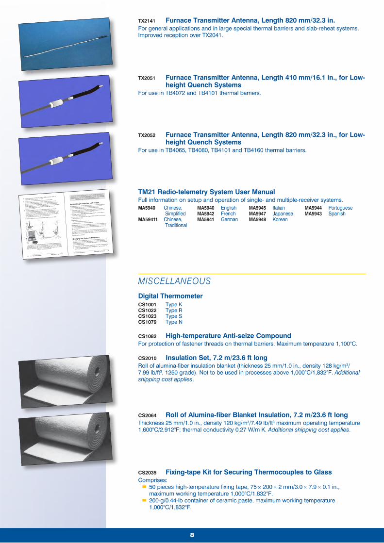
TX2040 Oven Transmitter Antenna, Length 410 mm/16.1 in.For general applications with Tpaq21 logger.
TX2041 Furnace Transmitter Antenna, Length 820 mm/32.3 in.For general furnace applications and in large-diameter special thermal barriers and slab-reheat systems.
8
TX2141 Furnace Transmitter Antenna, Length 820 mm/32.3 in.For general applications and in large special thermal barriers and slab-reheat systems. Improved reception over TX2041.
TX2051 Furnace Transmitter Antenna, Length 410 mm/16.1 in., for Low-height Quench Systems
For use in TB4072 and TB4101 thermal barriers.
TX2052 Furnace Transmitter Antenna, Length 820 mm/32.3 in., for Low-height Quench Systems
For use in TB4065, TB4080, TB4101 and TB4160 thermal barriers.
TM21 RADIO TELEMETRY Setting Up the System 17
16 Setting Up the System TM21 RADIO TELEMETRY
Rarely, cables between receivers over 30 m long may be subject to disruption of
communication due to strong power surges (e.g. from lightning). This is rectified by
powering the receivers off and on; communications should then resume and Insight
will continue to log incoming data from that point onwards.
Establishing Connection with Insight
If Insight has not previously been set up for use with radio-telemetry receivers,
or if the setup has been changed, it is necessary to inform Insight of the
receivers attached and to confirm correct connection as follows.
1. Ensure that the primary receiver and its power-supply unit, secondary
receivers (if used), antennas and PC are connected as detailed above, and
that the primary receiver’s power is switched on.
2. In Insight, open the Radio Receivers dialog (click on the toolbar, or
select View > Radio Receivers).
3. In the dialog, click Detect to make Insight find the receivers, and to display
information about them.
The dialog then shows:
• The radio frequency currently in use.
• The serial number of each receiver connected.
Where two or more secondary receivers are connected, their sequence in the
dialog will not necessarily be the same as that in which they are connected. If
you wish, you may correct this: click on the image of a receiver and drag it to
the correct position.
If a receiver is not detected initially, due to a connection or power problem, a
warning is displayed on the icon for that receiver. If preferred, you may remove
that receiver’s icon from the display: right-click on the icon and select ‘Remove’.
Close the dialog to proceed.
Changing the System’s Frequency
The TM21 system is supplied with transmitter(s) and receiver(s) configured so
that they operate on the same radio frequency and can thus communicate. The
system’s operating frequency can however be changed, if thought necessary, by
using the Insight software:
1. Ensure all (primary and secondary) receivers are connected, as detailed above.
2. In Insight, open the Radio Receivers dialog (click on the toolbar, or
select View > Radio Receivers).
5. If further secondary receivers are used, fit RS485 connection cables to
connect the receivers together in a chain.
6. Fit a terminator to the free socket of last receiver in the chain.
7. Switch on power to the primary receiver. If the PC is powered on, the
primary receiver’s display should show ‘PC OK’ to indicate a valid connection
to the PC (Insight does not need to be running). The primary receiver’s
display should also register that each of the secondary receivers is connected
(see p. 32 for details of the display). If this is not the case, check all
connections and retry.
8. Connect an antenna to each receiver. Receiver antennas can either be
mounted on Datapaq height-adjustable stands (p. 11) or attached to a
suitable available surface. In either case, antennas should be located at least
1 m away from any parallel conductive surface, e.g. metal-clad walls, steel
posts, large pipes. The location and orientation (vertical or horizontal) can
be optimized when the first profile run is carried out.
See above for choice of antennas and maximum length of antenna cables.
BB
A
C C
D
The setup for a TM21 radio-telemetry system with multiple receivers: primary
receiver (A) with whip antenna, and two secondary receivers (B) attached to unity-
gain end-feed antennas (C). Further secondary receivers may be added. The receiver
at the end of the chain is fitted with a terminator (D). Such a system may be suitable
for, e.g., a long continuous furnace.
TM21 Radio-telemetry System User ManualFull information on setup and operation of single- and multiple-receiver systems.MA5940 Chinese,
SimplifiedMA59411 Chinese,
Traditional
MA5940 EnglishMA5942 FrenchMA5941 German
MA5945 ItalianMA5947 JapaneseMA5948 Korean
MA5944 PortugueseMA5943 Spanish
MISCELLANEOUS
Digital ThermometerCS1001 Type KCS1022 Type RCS1023 Type SCS1079 Type N
CS1082 High-temperature Anti-seize CompoundFor protection of fastener threads on thermal barriers. Maximum temperature 1,100°C.
CS2010 Insulation Set, 7.2 m/23.6 ft longRoll of alumina-fiber insulation blanket (thickness 25 mm/1.0 in., density 128 kg/m3/ 7.99 lb/ft3, 1250 grade). Not to be used in processes above 1,000°C/1,832°F. Additional shipping cost applies.
CS2064 Roll of Alumina-fiber Blanket Insulation, 7.2 m/23.6 ft longThickness 25 mm/1.0 in., density 120 kg/m3/7.49 lb/ft3 maximum operating temperature 1,600°C/2,912°F; thermal conductivity 0.27 W/m K. Additional shipping cost applies.
CS2035 Fixing-tape Kit for Securing Thermocouples to GlassComprises:
�� 50 pieces high-temperature fixing tape, 75 × 200 × 2 mm/3.0 × 7.9 × 0.1 in., maximum working temperature 1,000°C/1,832°F.�� 200-g/0.44-lb container of ceramic paste, maximum working temperature 1,000°C/1,832°F.
99
CS3085 Stainless-steel Wire, 250 m/820 ft
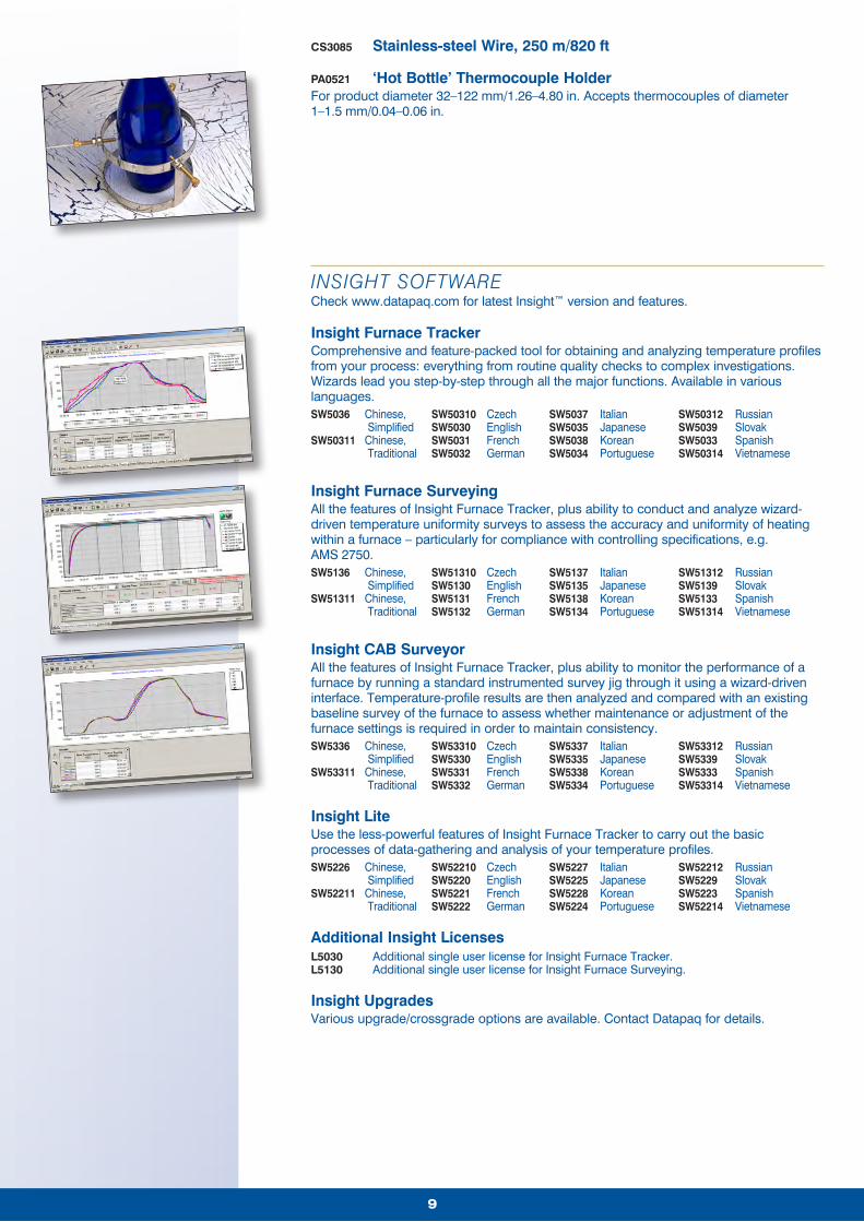
PA0521 ‘Hot Bottle’ Thermocouple HolderFor product diameter 32–122 mm/1.26–4.80 in. Accepts thermocouples of diameter 1–1.5 mm/0.04–0.06 in.
INSIGHT SOFTWARECheck www.datapaq.com for latest Insight™ version and features.
Insight Furnace TrackerComprehensive and feature-packed tool for obtaining and analyzing temperature profiles from your process: everything from routine quality checks to complex investigations. Wizards lead you step-by-step through all the major functions. Available in various languages.SW5036 Chinese, SW50310 Czech SW5037 Italian SW50312 Russian Simplified SW5030 English SW5035 Japanese SW5039 SlovakSW50311 Chinese, SW5031 French SW5038 Korean SW5033 Spanish Traditional SW5032 German SW5034 Portuguese SW50314 Vietnamese
Insight Furnace SurveyingAll the features of Insight Furnace Tracker, plus ability to conduct and analyze wizard-driven temperature uniformity surveys to assess the accuracy and uniformity of heating within a furnace – particularly for compliance with controlling specifications, e.g. AMS 2750.SW5136 Chinese, SW51310 Czech SW5137 Italian SW51312 Russian Simplified SW5130 English SW5135 Japanese SW5139 SlovakSW51311 Chinese, SW5131 French SW5138 Korean SW5133 Spanish Traditional SW5132 German SW5134 Portuguese SW51314 Vietnamese
Insight CAB SurveyorAll the features of Insight Furnace Tracker, plus ability to monitor the performance of a furnace by running a standard instrumented survey jig through it using a wizard-driven interface. Temperature-profile results are then analyzed and compared with an existing baseline survey of the furnace to assess whether maintenance or adjustment of the furnace settings is required in order to maintain consistency.SW5336 Chinese, SW53310 Czech SW5337 Italian SW53312 Russian Simplified SW5330 English SW5335 Japanese SW5339 SlovakSW53311 Chinese, SW5331 French SW5338 Korean SW5333 Spanish Traditional SW5332 German SW5334 Portuguese SW53314 Vietnamese
Insight LiteUse the less-powerful features of Insight Furnace Tracker to carry out the basic processes of data-gathering and analysis of your temperature profiles.SW5226 Chinese, SW52210 Czech SW5227 Italian SW52212 Russian Simplified SW5220 English SW5225 Japanese SW5229 SlovakSW52211 Chinese, SW5221 French SW5228 Korean SW5223 Spanish Traditional SW5222 German SW5224 Portuguese SW52214 Vietnamese
Additional Insight LicensesL5030 Additional single user license for Insight Furnace Tracker.L5130 Additional single user license for Insight Furnace Surveying.
Insight UpgradesVarious upgrade/crossgrade options are available. Contact Datapaq for details.
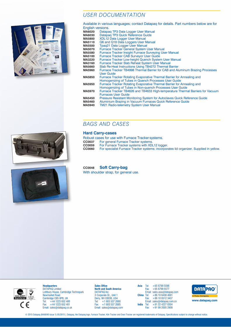
Available in various languages; contact Datapaq for details. Part numbers below are for English versions.MA6020 Datapaq TP3 Data Logger User ManualMA6030 Datapaq TP3 Quick Reference GuideMA5800 XDL12 Data Logger User ManualMA5110 Q6 and Q18 Data Loggers User ManualMA5500 Tpaq21 Data Logger User ManualMA5070 Furnace Tracker General System User ManualMA5580 Furnace Tracker Insight Furnace Surveying User ManualMA5100 Furnace Tracker CAB Surveyor User GuideMA3220 Furnace Tracker Low-height Quench System User ManualMA3160 Furnace Tracker Slab Reheat System User ManualMA5660 Slab Re-Heat Instructions Using TB4272 Thermal BarrierMA5960 Furnace Tracker TB4998 Thermal Barrier for CAB and Aluminum Brazing Processes
User GuideMA5850 Furnace Tracker Rotating Evaporative Thermal Barrier for Annealing and
Homogenizing of Tubes in Quench Processes User GuideMA5950 Furnace Tracker Rotating Evaporative Thermal Barrier for Annealing and
Homogenizing of Tubes in Non-quench Processes User GuideMA5970 Furnace Tracker TB4626 and TB4633 High-temperature Thermal Barriers for Vacuum
Furnaces User GuideMA5450 Pressure Resistant Monitoring System for Autoclaves Quick Reference GuideMA5460 Aluminium Brazing in Vacuum Furnaces Quick Reference GuideMA5940 TM21 Radio-telemetry System User Manual
BAGS AND CASES
Hard Carry-casesRobust cases for use with Furnace Tracker systems.CC0037 For general Furnace Tracker systems.CC0059 For Furnace Tracker systems with XDL12 logger.CC0060 For specialist Furnace Tracker systems; incorporates lid organizer. Supplied in yellow.
CC0048 Soft Carry-bagWith shoulder strap, for general use.