SHORT PAPERS AND CLASSROOM NOTES VC E RI * L=O -LARGER L Fig. 3. Response of RLC circuit. VC E R L0O SMALL L LARGER L iE tRCTERM L=0 SMALL L' LARGER L "r -_, t/Rrf T - Ec TERM Fig. 4. Response of R.aLC circuit. replace the capacitor by a voltage source equal to the initial capacitor voltage. For the resultant RnL circuit, the current is given by i4(t) = _E -vo E-vo >RatL (5) Rn no+ f R, R,~ vO and io are the initial capacitor voltage and current at the instant the circuit enters the negative resistance region (taken as t = 0), and their positive direction is defined in Fig. 2. The direction of the cur- rent jump is then determined by the sign of the term [io + (E -vo) /R 1. As the final step in the circuit analysis, we replace the capacitor by a current source of value i (t) and determine the direction of the jumps of all other currents and voltages in the negative resistance circuit. I. INTRODUCTION It was shown in a recent article [I ] that for a general symmetrical network, symmetrical excitation produces symmetrical responses and that antisymmetrical excitation produces antisymmetrical responses. These facts were used to demonstrate that under one form of excita- tion or the other, it is possible to open or short circuit some of the middle terminals without affecting the response of the rest of the net- work. The purpose here is to investigate the effect of open or short circuiting some of the middle terminals under general excitation, i.e., neither symmetrical nor antisymmetrical. II. NETWORK RESTRICTIONS The main tool used in this investigation is superposition. This necessitates that the network be linear and bilateral. It could contain distributed as well as lumped elements, time-varying elements, mu- tual coupling, and controlled sources. The latter two types of ele- ments could have their controlling variables within the section or in the other section. Fig. 1 shows a typical arrangement for such a network, consisting of two identical sections (excited differently) connected by straight and crossed middle terminals. There are no restrictions whatsoever on the excitation. Initial values of voltages and currents are considered here a part of the excitation. III. SHORT-CIRCUIT EFFECT Consider first the effect of short-circuiiting two of the straight middle terminals, those marked a and b in Fig. 1, for example. Any response r in the network can be considered (using superposition with variables [2]) as r = r(excitation, Vab = 0) + r(Vab), (1) where r(Vab) is the response r that would result if all excitations were made zero and a source Vab is connected between terminals a and b, while r (excitation, Vab = 0) is the response r that would result in the original network if the terminals a and b were short-circuited. Any response r that has r(vab) =0 will be equal to r(excitation, Vab=O) and, therefore, will not be affected by short circuiting the a and b terminals. In order to locate such responses, imagine that a voltage source Vab is inserted between terminals a and b, and that all the excitations in the network are removed. The network becomes symmetrically excited with the result [1] ij(Vab)= 0 and ec(vab) = 0, where ij is a current in any straight middle terminal (excluding ter- minals a and b) and e, is the voltage across any pair of crossed middle terminals. From this it is easily seen that in a linear bilateral symmetrical network with any form of excitation, short circuiting any number of straight middle ter- minals has no effect whatsoever on the currents in the rest of the straight middle terminals, nor has it any effect on the voltages across any pair of crossed middle terminals. The effect of short-circuiting a pair of crossed middle terminals (the terminals with the voltage e, in Fig. 1, for example) can be seen by writing r = r(excitation, e, = 0) + r(e,), (2) Further Properties of Symmetrical Networks M. F. MOAD, SENIOR MEMBER, IEEE Abstract-Properties of symmetrical networks are usually ob- tained through symmetrical and antisymmetrical excitations. A dif- ferent approach that reveals new properties for symmetrical net- works, under any form of excitation, is presented. This approach il- lustrates one of the advantages of using superposition with variables and sources. Manuscript received March 8, 1968. The author is with the School of Electrical Engineering, Georgia Institute of Technology. Atlanta, Ga. where r(e,) is the response r that would result if all excitations were removed and a voltage source e, were inserted in place of the response e,. It is evident that r(e,) produces an antisymmetrical excitation. Such an excitation leads to vo, (e) = 0, which, together with (2), can be interpreted as follows: in a linear bilateral symmetrical network with any form of excitation, short-circuiting any pair of crossed middle terminals has no effect whatsoever on the voltages across the straight middle terminals. IV. OPEN-CIRCUIT EFFECT The effect of open circuiting one of the straight middle terminals t 205
Transcript
SHORT PAPERS AND CLASSROOM NOTES
VC
ERI *L=O
-LARGER L
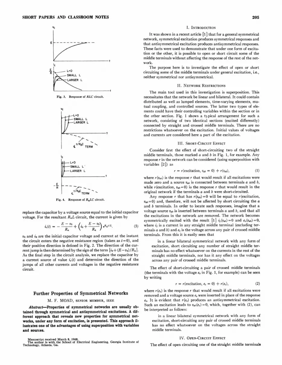
Fig. 3. Response of RLC circuit.
VC
ER
L0OSMALL LLARGER L
iEtRCTERM
L=0SMALL L'LARGER L
"r -_,t/RrfT -
Ec TERM
Fig. 4. Response of R.aLC circuit.
replace the capacitor by a voltage source equal to the initial capacitorvoltage. For the resultant RnL circuit, the current is given by
i4(t) = _E -vo E-vo >RatL (5)Rn no+ f
R, R,~
vO and io are the initial capacitor voltage and current at the instantthe circuit enters the negative resistance region (taken as t = 0), andtheir positive direction is defined in Fig. 2. The direction of the cur-rent jump is then determined by the sign of the term [io+ (E -vo)/R 1.As the final step in the circuit analysis, we replace the capacitor bya current source of value i (t) and determine the direction of thejumps of all other currents and voltages in the negative resistancecircuit.
I. INTRODUCTION
It was shown in a recent article [I ] that for a general symmetricalnetwork, symmetrical excitation produces symmetrical responses andthat antisymmetrical excitation produces antisymmetrical responses.These facts were used to demonstrate that under one form of excita-tion or the other, it is possible to open or short circuit some of themiddle terminals without affecting the response of the rest of the net-work.
The purpose here is to investigate the effect of open or shortcircuiting some of the middle terminals under general excitation, i.e.,neither symmetrical nor antisymmetrical.
II. NETWORK RESTRICTIONS
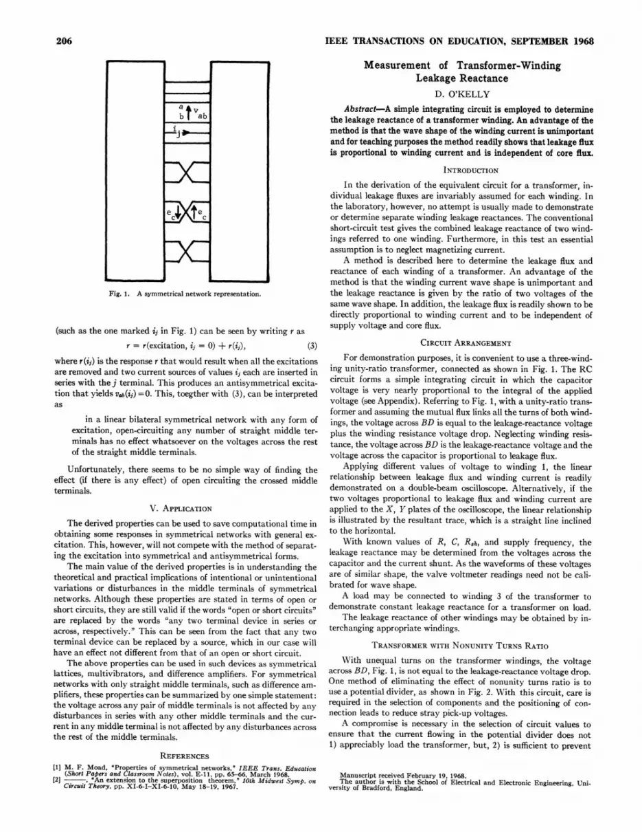
The main tool used in this investigation is superposition. Thisnecessitates that the network be linear and bilateral. It could containdistributed as well as lumped elements, time-varying elements, mu-tual coupling, and controlled sources. The latter two types of ele-ments could have their controlling variables within the section or inthe other section. Fig. 1 shows a typical arrangement for such anetwork, consisting of two identical sections (excited differently)connected by straight and crossed middle terminals. There are norestrictions whatsoever on the excitation. Initial values of voltagesand currents are considered here a part of the excitation.
III. SHORT-CIRCUIT EFFECT
Consider first the effect of short-circuiiting two of the straightmiddle terminals, those marked a and b in Fig. 1, for example. Anyresponse r in the network can be considered (using superposition withvariables [2]) as
r = r(excitation, Vab = 0) + r(Vab), (1)where r(Vab) is the response r that would result if all excitations weremade zero and a source Vab is connected between terminals a and b,while r (excitation, Vab = 0) is the response r that would result in theoriginal network if the terminals a and b were short-circuited.
Any response r that has r(vab) =0 will be equal to r(excitation,Vab=O) and, therefore, will not be affected by short circuiting the aand b terminals. In order to locate such responses, imagine that avoltage source Vab is inserted between terminals a and b, and that allthe excitations in the network are removed. The network becomessymmetrically excited with the result [1] ij(Vab)=0 and ec(vab) = 0,where ij is a current in any straight middle terminal (excluding ter-minals a and b) and e, is the voltage across any pair of crossed middleterminals. From this it is easily seen that
in a linear bilateral symmetrical network with any form ofexcitation, short circuiting any number of straight middle ter-minals has no effect whatsoever on the currents in the rest of thestraight middle terminals, nor has it any effect on the voltagesacross any pair of crossed middle terminals.
The effect of short-circuiting a pair of crossed middle terminals(the terminals with the voltage e, in Fig. 1, for example) can be seenby writing
r = r(excitation, e, = 0) + r(e,), (2)
Further Properties of Symmetrical NetworksM. F. MOAD, SENIOR MEMBER, IEEE
Abstract-Properties of symmetrical networks are usually ob-tained through symmetrical and antisymmetrical excitations. A dif-ferent approach that reveals new properties for symmetrical net-works, under any form of excitation, is presented. This approach il-lustrates one of the advantages of using superposition with variablesand sources.
Manuscript received March 8, 1968.The author is with the School of Electrical Engineering, Georgia Institute of
Technology. Atlanta, Ga.
where r(e,) is the response r that would result if all excitations wereremoved and a voltage source e, were inserted in place of the responsee,. It is evident that r(e,) produces an antisymmetrical excitation.Such an excitation leads to vo,(e) =0, which, together with (2), canbe interpreted as follows:
in a linear bilateral symmetrical network with any form ofexcitation, short-circuiting any pair of crossed middle terminalshas no effect whatsoever on the voltages across the straightmiddle terminals.
IV. OPEN-CIRCUIT EFFECT
The effect of open circuiting one of the straight middle terminals
t
205
IEEE TRANSACTIONS ON EDUCATION, SEPTEMBER 1968
IX
PC
Fig. 1. A symmetrical network representation.
(such as the one marked ij in Fig. 1) can be seen by writing r as
r = r(excitation, ij = 0) + r(ij), (3)where r(ij) is the response r that would result when all the excitationsare removed and two current sources of values ij each are inserted inseries with the j terminal. This produces an antisymmetrical excita-tion that yields Vab(ij) =0. This, toegther with (3), can be interpretedas
in a linear bilateral symmetrical network with any form ofexcitation, open-circuiting any number of straight middle ter-minals has no effect whatsoever on the voltages across the restof the straight middle terminals.
Unfortunately, there seems to be no simple way of finding theeffect (if there is any effect) of open circuiting the crossed middleterminals.
V. APPLICATIONThe derived properties can be used to save computational time in
obtaining some responses in symmetrical networks with general ex-citation. This, however, will not compete with the method of separat-ing the excitation into symmetrical and antisymmetrical forms.
The main value of the derived properties is in understanding thetheoretical and practical implications of intentional or unintentionalvariations or disturbances in the middle terminals of symmetricalnetworks. Although these properties are stated in terms of open orshort circuits, they are still valid if the words "open or short circuits"are replaced by the words "any two terminal device in series oracross, respectively." This can be seen from the fact that any twoterminal device can be replaced by a source, which in our case willhave an effect not different from that of an open or short circuit.
The above properties can be used in such devices as symmetricallattices, multivibrators, and difference amplifiers. For symmetricalnetworks with only straight middle terminals, such as difference am-plifiers, these properties can be summarized by one simple statement:the voltage across any pair of middle terminals is not affected by anydisturbances in series with any other middle terminals and the cur-rent in any middle terminal is not affected by any disturbances acrossthe rest of the middle terminals.
REFERENCES[1] M. F. Moad, "Properties of symmetrical networks,' IEEE Trans. Education
(Short Papers and Classroom Notes), vol. E-11, pp. 65-66, March 1968.[2] , 'An extension to the superposition theorem," 10th Midwest Symp. onCircuit Theory. pp. XI-6-I-XI-6-10, May 18-19, 1967.
Measurement of Transformer-WindingLeakage Reactance
D. O'KELLYAbstract-A simple integrating circuit is employed to determine
the leakage reactance of a transformer winding. An advantage of themethod is that the wave shape of the winding current is unimportantand for teaching purposes the method readily shows that leakage fluxis proportional to winding current and is independent of core flux.
INTRODUCTION
In the derivation of the equivalent circuit for a transformer, in-dividual leakage fluxes are invariably assumed for each winding. Inthe laboratory, however, no attempt is usually made to demonstrateor determine separate winding leakage reactances. The conventionalshort-circuit test gives the combined leakage reactance of two wind-ings referred to one winding. Furthermore, in this test an essentialassumption is to neglect magnetizing current.
A method is described here to determine the leakage flux andreactance of each winding of a transformer. An advantage of themethod is that the winding current wave shape is unimportant andthe leakage reactance is given by the ratio of two voltages of thesame wave shape. In addition, the leakage flux is readily shown to bedirectly proportional to winding current and to be independent ofsupply voltage and core flux.
CIRCUIT ARRANGEMENTFor demonstration purposes, it is convenient to use a three-wind-
ing unity-ratio transformer, connected as shown in Fig. 1. The RCcircuit forms a simple integrating circuit in which the capacitorvoltage is very nearly proportional to the integral of the appliedvoltage (see Appendix). Referring to Fig. 1, with a unity-ratio trans-former and assuming the mutual flux links all the turns of both wind-ings, the voltage across BD is equal to the leakage-reactance voltageplus the winding resistance voltage drop. Neglecting winding resis-tance, the voltage across BD is the leakage-reactance voltage and thevoltage across the capacitor is proportional to leakage flux.
Applying different values of voltage to winding 1, the linearrelationship between leakage flux and winding current is readilydemonstrated on a double-beam oscilloscope. Alternatively, if thetwo voltages proportional to leakage flux and winding current areapplied to the X, Y plates of the oscilloscope, the linear relationshipis illustrated by the resultant trace, which is a straight line inclinedto the horizontal.
With known values of R, C, Rsh, and supply frequency, theleakage reactance may be determined from the voltages across thecapacitor and the current shunt. As the waveforms of these voltagesare of similar shape, the valve voltmeter readings need not be cali-brated for wave shape.
A load may be connected to winding 3 of the transformer todemonstrate constant leakage reactance for a transformer on load.
The leakage reactance of other windings may be obtained by in-terchanging appropriate windings.
TRANSFORMER WITH NONUNITY TURNS RATIO
With unequal turns on the transformer windings, the voltageacross BD, Fig. 1, is not equal to the leakage-reactance voltage drop.One method of eliminating the effect of nonunity turns ratio is touse a potential divider, as shown in Fig. 2. With this circuit, care isrequired in the selection of components and the positioning of con-nection leads to reduce stray pick-up voltages.
A compromise is necessary in the selection of circuit values toensure that the current flowing in the potential divider does not1) appreciably load the transformer, but, 2) is sufficient to prevent
Manuscript received February 19, 1968.The author is with the School of Electrical and Electronic Engineering, Uni-