15
FUSE CATALOG
| Date post: | 22-Aug-2019 |
| Category: |
Documents |
| Upload: | nguyenquynh |
| View: | 230 times |
| Download: | 0 times |

FUSECATALOG

2
Table 1.-Elemsa code and characteristics of Type K fuse links (Fast).
Note.-Fuse links have removable head for installation on distribution fuse cutouts.
TYPE DESCRIPTION CAT PAGE15K-1 UNIVERSAL TYPE FUSE LINK 2066A1
38K-1 UNIVERSAL TYPE FUSE LINK 2070A1
15K-2 UNIVERSAL TYPE FUSE LINK 2066A2
38K-2 UNIVERSAL TYPE FUSE LINK 2070A2
15K-3 UNIVERSAL TYPE FUSE LINK 2066A3
38K-3 UNIVERSAL TYPE FUSE LINK 2070A3
15K-5 UNIVERSAL TYPE FUSE LINK 2066A4
38K-5 UNIVERSAL TYPE FUSE LINK 2070A4
15K-6 UNIVERSAL TYPE FUSE LINK 000258
38K-6 UNIVERSAL TYPE FUSE LINK
15K-7 UNIVERSAL TYPE FUSE LINK 000260
38K-7 UNIVERSAL TYPE FUSE LINK
15K-8 UNIVERSAL TYPE FUSE LINK 2066A5
38K-8 UNIVERSAL TYPE FUSE LINK 2070A5
15K-10 UNIVERSAL TYPE FUSE LINK 2066A6
38K-10 UNIVERSAL TYPE FUSE LINK 2070A6
15K-12 UNIVERSAL TYPE FUSE LINK 2066A7
38K-12 UNIVERSAL TYPE FUSE LINK 2070A7
15K-15 UNIVERSAL TYPE FUSE LINK 2066A8
38K-15 UNIVERSAL TYPE FUSE LINK 2070A8
15K-20 UNIVERSAL TYPE FUSE LINK 000269
38K-20 UNIVERSAL TYPE FUSE LINK
TYPE DESCRIPTION CAT PAGE15K-25 UNIVERSAL TYPE FUSE LINK 2066A9
38K-25 UNIVERSAL TYPE FUSE LINK
15K-30 UNIVERSAL TYPE FUSE LINK 000273
38K-30 UNIVERSAL TYPE FUSE LINK
15K-40 UNIVERSAL TYPE FUSE LINK 2066AA
38K-40 UNIVERSAL TYPE FUSE LINK
15K-50 UNIVERSAL TYPE FUSE LINK 000277
38K-50 UNIVERSAL TYPE FUSE LINK
15K-65 UNIVERSAL TYPE FUSE LINK 2068A1
38K-65 UNIVERSAL TYPE FUSE LINK
15K-80 UNIVERSAL TYPE FUSE LINK 000282
38K-80 UNIVERSAL TYPE FUSE LINK
15K-100 UNIVERSAL TYPE FUSE LINK 000285
38K-100 UNIVERSAL TYPE FUSE LINK

3
Table 2.-Elemsa code and characteristics of Type T fuse links (Slow).
Note.-Fuse links have removable head for installation on distribution fuse cutouts.
TYPE DESCRIPTION CAT PAGE15T-6 UNIVERSAL TYPE FUSE LINK
38T-6 UNIVERSAL TYPE FUSE LINK
15T-8 UNIVERSAL TYPE FUSE LINK
38T-8 UNIVERSAL TYPE FUSE LINK
15T-10 UNIVERSAL TYPE FUSE LINK 2068A1
38T-10 UNIVERSAL TYPE FUSE LINK 2072A1
15T-12 UNIVERSAL TYPE FUSE LINK 2068A2
38T-12 UNIVERSAL TYPE FUSE LINK 2072A2
15T-15 UNIVERSAL TYPE FUSE LINK 2068A3
38T-15 UNIVERSAL TYPE FUSE LINK 2072A3
15T-20 UNIVERSAL TYPE FUSE LINK 2068A4
38T-20 UNIVERSAL TYPE FUSE LINK 2072A4
15T-25 UNIVERSAL TYPE FUSE LINK 2068A5
38T-25 UNIVERSAL TYPE FUSE LINK 2072A5
15T-30 UNIVERSAL TYPE FUSE LINK 2068A6
38T-30 UNIVERSAL TYPE FUSE LINK 2072A6
15T-40 UNIVERSAL TYPE FUSE LINK 2068A7
38T-40 UNIVERSAL TYPE FUSE LINK 2072A7
15T-50 UNIVERSAL TYPE FUSE LINK 2068A8
38T-50 UNIVERSAL TYPE FUSE LINK 2072A8
TYPE DESCRIPTION CAT PAGE15T-65 UNIVERSAL TYPE FUSE LINK 2068A9
38T-65 UNIVERSAL TYPE FUSE LINK 2072A9
15T-80 UNIVERSAL TYPE FUSE LINK 2068AA
38T-80 UNIVERSAL TYPE FUSE LINK
15T-85 UNIVERSAL TYPE FUSE LINK 2068AB
38T-85 UNIVERSAL TYPE FUSE LINK
15T-100 UNIVERSAL TYPE FUSE LINK 2068AC
38T-100 UNIVERSAL TYPE FUSE LINK

4
Table 3.-Elemsa code and characteristics of Type F fuse links (Fractional).
Note.-Fuse links have removable head for installation on distribution fuse cutouts.
TYPE DESCRIPTION15F-0.33 STANDARD TYPE FUSE LINK
38F-0.33 STANDARD TYPE FUSE LINK
15F-0.5 STANDARD TYPE FUSE LINK
38F-0.5 STANDARD TYPE FUSE LINK
15F-0.75 STANDARD TYPE FUSE LINK
38F-0.75 STANDARD TYPE FUSE LINK
15F-1.0 STANDARD TYPE FUSE LINK
38F-1.0 STANDARD TYPE FUSE LINK
15F-1.25 STANDARD TYPE FUSE LINK
38F-1.25 STANDARD TYPE FUSE LINK
15F-1.5 STANDARD TYPE FUSE LINK
38F-1.5 STANDARD TYPE FUSE LINK
15F-2.0 STANDARD TYPE FUSE LINK
38F-2.0 STANDARD TYPE FUSE LINK
15F-2.5 STANDARD TYPE FUSE LINK
38F-2.5 STANDARD TYPE FUSE LINK
15F-3.5 STANDARD TYPE FUSE LINK
38F-3.5 STANDARD TYPE FUSE LINK
15F-4.0 STANDARD TYPE FUSE LINK
38F-4.0 STANDARD TYPE FUSE LINK
TYPE DESCRIPTION15S-1 STANDARD TYPE FUSE LINK
38S-1 STANDARD TYPE FUSE LINK
15S-2 STANDARD TYPE FUSE LINK
38S-2 STANDARD TYPE FUSE LINK
15S-3 STANDARD TYPE FUSE LINK
38S-3 STANDARD TYPE FUSE LINK
15S-5 STANDARD TYPE FUSE LINK
38S-5 STANDARD TYPE FUSE LINK

5

6
Minimum melting time for universal Type “K” fuse (Fast).

7
Total clearing time for universal Type “K” link fuse (Fast).

8
Minimum melting time for universal Type “T“ fuse link (Slow).

9
Total clearing time for universal Type “T” link fuse (Slow).

10
Fuse Application.
Proper application of fuse links requires knowledge of the system and the equipment that needs pro-tection. For coordination purposes, the short-circuit current rating, inrush current, and load current at the point of application must be known.
Operating variables.
The effects of the following operating variables must be considered when selecting the fuses.
1.- Preload: because the load current is not necessarily in direct proportion to the nominal capacity of the fuse, but rather depending of the magnitude and duration of the current. Preload increases the temperature of the fuse, thus reducing the melting time of the fuse element for all the values of the short-circuit current.
2.- You can consider ambient temperature as the same for all the fuses in the same circuit. The ti-me-current curves are based on testing carried out on fuses at ambient temperatures from 20º C. to 30º C. When ambient temperature increases, melting time is reduced.
3.- The melting heat refers to the necessary heat to turn a solid in its fusion temperature to liquid in the same temperature. Short duration short-circuit currents can provide a part of the melting heat that can damage the fuse section, causing a partial melt - A fuse affected with this partial melting can exhibit the characteristics of reduced melting time.

11
Rules for Fuse application.
By convention, when you apply two or more fuse links or any other production device to a system, the device closest to the fault on the energy input side becomes the “protecting” or main fuse device, and the closest to the energy supply is the “protected” or backup fuse device. The following diagram depicts this situation.
PROTECTED FUSE
SUBSTATION
PROTECTORFUSE
PROTECTORFUSE
A special rule for the application of fuses, establishes that the maximum clearing time of the protector fuse, must not exceed 75% of the minimum melting time of the protected fuse. This principle ensures that the protector fuse interrupts and clears the fault before the protected fuse is affected in any way. The 75% factor compensates for operating variables like, initial preload, ambient temperature and melting heat.
Another important rule states that the load current at the fuse application spot must not exceed the fuse’s continuous current capacity.
12
If the load current were to exceed the fuse’s capacity, the fuse can heat-up, break and cause an unne-cessary interruption. The continuous current capacity is about 1.50 of the nominal capacity.
Criteria for coordination.
1.- The protector device must clear a transient or permanent fault before the protected device inte-rrupts the circuit or triggers a recloser to operate.
2.- Interruptions originated by permanent faults must be restricted to the smallest part of the system for the shortest time possible.
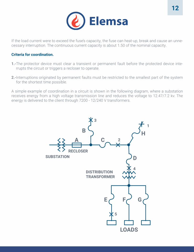
A simple example of coordination in a circuit is shown in the following diagram, where a substation receives energy from a high voltage transmission line and reduces the voltage to 12.47/7.2 kv. The energy is delivered to the client through 7200 - 12/240 V transformers.
DISTRIBUTIONTRANSFORMER
SUBSTATIONRECLOSER
31
2
4
5
A CB
D
E F G
LOADS
H

13
Protector devices in this diagram are located at the coordination points. Device A is at the substation. Devices C and H are at the feeder. Device D is at the transformer’s primary, and devices E, F and G are fuses at the services input on the transformer’s secondary.
All devices and fuses must be selected to withstand normal load current and properly respond to a fault current. In relation to device H, device C is the protected device.
When a fault occurs at point 1, device C must not clear, device H must intervene.
In relation to device A, device C is the protector and must clear the permanent fault current from point 2 before recloser A operates. Device B is also the protector of A and must have a similar operation as C. For a transformer fault at point 4, device D must interrupt normal current in the rest of the system.
When a fault occurs at point 5, at a tap of the transformer’s secondary, device E must interrupt, allowing energy to continue flowing to the transformer so that other clients of the secondary taps continue to be serviced.
Fuse to fuse coordination. Fuse coordination can be achieved by using the time-current curves, coordi-nation tables or rules already established by the industry through empirical methods (“Rules of thumb”). In that order the methods given are progressively easier to use, however the empirical method doesn’t provide the preferable coordination that time-current curves or coordination tables do, but it’s less work. When coordination of a short-circuit current must be extended to the maximum range, the empirical method is not recommended.
14
Time-Current Curves.
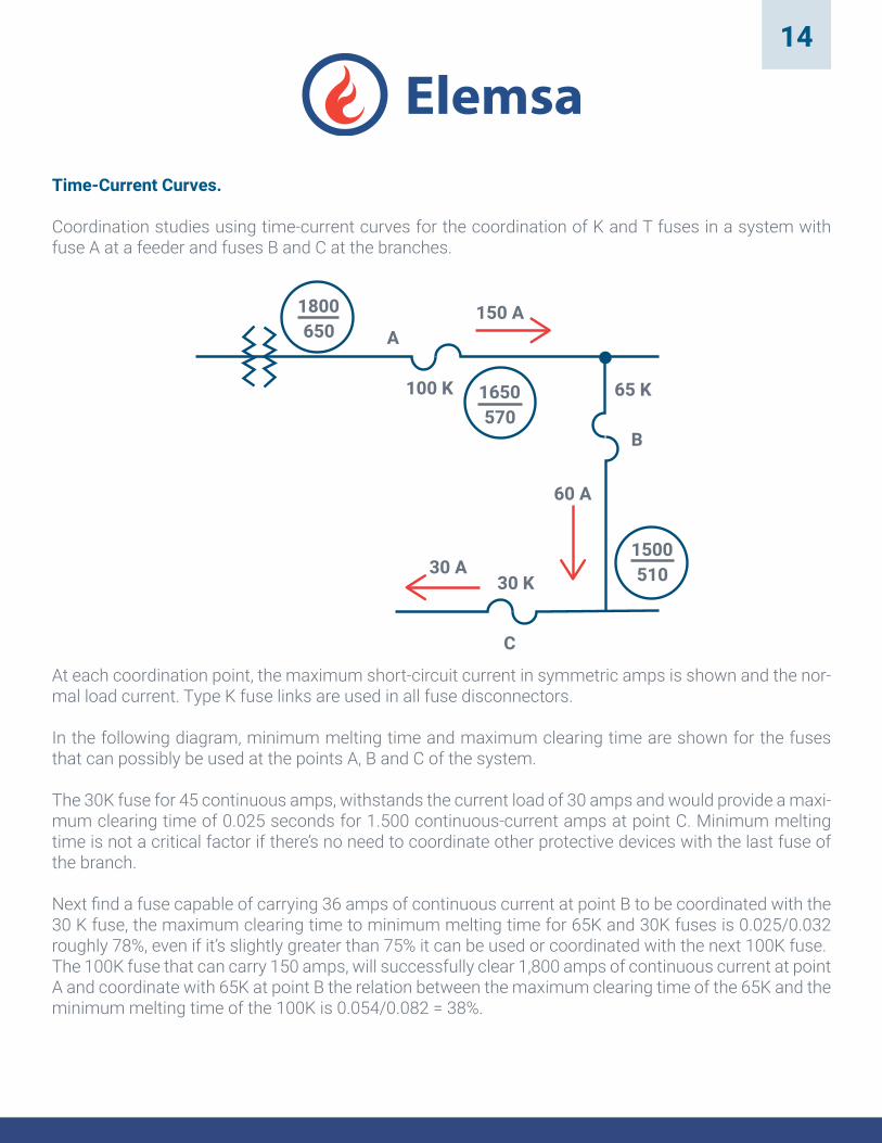
Coordination studies using time-current curves for the coordination of K and T fuses in a system with fuse A at a feeder and fuses B and C at the branches.
1800650
1650570
1500510
65 K
60 A
30 A30 K
C
B
150 AA
100 K
At each coordination point, the maximum short-circuit current in symmetric amps is shown and the nor-mal load current. Type K fuse links are used in all fuse disconnectors.
In the following diagram, minimum melting time and maximum clearing time are shown for the fuses that can possibly be used at the points A, B and C of the system.
The 30K fuse for 45 continuous amps, withstands the current load of 30 amps and would provide a maxi-mum clearing time of 0.025 seconds for 1.500 continuous-current amps at point C. Minimum melting time is not a critical factor if there’s no need to coordinate other protective devices with the last fuse of the branch.
Next find a fuse capable of carrying 36 amps of continuous current at point B to be coordinated with the 30 K fuse, the maximum clearing time to minimum melting time for 65K and 30K fuses is 0.025/0.032 roughly 78%, even if it’s slightly greater than 75% it can be used or coordinated with the next 100K fuse. The 100K fuse that can carry 150 amps, will successfully clear 1,800 amps of continuous current at point A and coordinate with 65K at point B the relation between the maximum clearing time of the 65K and the minimum melting time of the 100K is 0.054/0.082 = 38%.

15
Approximate rules.
Approximate rules have been established for fuse coordination of the same type and category with EEI-NEMA standards.
1.- Type K fuse links can provide satisfactory coordination between adjacent capacities in the same se-ries for current values up to 13 times the capacity of the protected fuse.
2.- And for Type T up to 24 times the capacity of the protected fuse.
Approximate rules are very useful in systems where the fault current decreases proportionally in a linear form according to approximate coordination points.
The 12 amps load current at point C suggests a 10K fuse, that will coordinate with the next fuse in the series, of 15 K, up to 156 amps. As the available fault current at point B is 150 amps, 10K and 15K fuses will have satisfactory coordination. The requirements of the load current are also satisfied by the 15K fuse.
A 25K fuse coordinates with a 15K up to 325 amps and coordination is achieved because the fault cu-rrent at point A is only up to 200 amps.
C
B
A
25 K
32 A
20 A
15 K
10 K
12 A
200
150
100


