44
Manual: DL16301 Revision: B 12/14 Fusion Joint Verification and Documentation Operator’s Manual Original Language: English 5

Manual: DL16301 Revision: B 12/14
Fusion Joint Verification and Documentation
Operator’sManual
Original Language: English
5

This product and other products could be protected by patents or
have patents pending. All the latest patent information is available at
patent.mcelroy.com

Thank You for purchasing thisMcElroy product.McElroy’s DataLogger® 5 system uses the DataLogger® handheld computer with a pressure sender to record information in the making of pipe fusion joints. The DataLogger 5 pressure sender reads pressures up to 3000 psi. The DataLogger 5 is compact, it logs a report for each joint and stores it on the handheld computer. The DL5m software is available in multiple languages and has FusionGuide ™ visual assistant that color codes the produced graphs for better interpretation.
The McElroy DataLogger® 5 system consists of a pressure sender, the DataLogger handheld computer, and optional accessories. In addition to providing a user interface, the handheld computer is capable of storing hundreds of reports limited only by its memory capacity. For example, a computer with 20MB of user accessible memory can store up to 10,000 reports that are 2Kbytes in length. (Note: although the computer has the capacity, you are strongly advised to upload joint report data to DataLogger® Vault™ for permanent online storage and easy access).
IMPORTANT: Please take every precaution to safeguard your joint report files. Make backups often. McElroy cannot guarantee the safety and integrity of joint reports beyond the specification of component manufacturers and the handling of equipment in the field.TX04598-10-30-13
Introduction
McElroy UniversityFor more than 30 years, McElroy has been the only pipe fusion machine manufacturer to continuously offer advanced training. Course offerings are meant to enhance your efficiency, productivity and safety in the proper use of McElroy machines. McElroy University classes are structured so that the skills learned and the machines used in each class closely match the machines found on pipelining jobsites. We offer training at our facility or yours. Our uniquely qualified McElroy University course instructors offer years of industry experience.
Tuition for each course includes lunches, course materials and a certificate of completion. Online registration, as well as up-to-date course offerings and dates, is available at www.mcelroy.com/university
This manual is intended as a guide only and does not take the place of proper training by qualified instructors. The information in this manual is not all inclusive and can not encompass all possible situations that can be encountered during various operations.
MU
2-03
-13-
14
TX04659-03-24-14

Warranty
LIMITED WARRANTYMcElroy Manufacturing, Inc. (McElroy) warrants all products manufactured, sold and repaired by it to be free from defects in materials and workmanship, its obligation under this warranty being limited to repairing or replacing at its factory and new products, within 5 years after shipment, with the exception of purchased items (such as electronic devices, pumps, switches, etc.), in which case that manufacturer’s warranty applies. Warranty applies when returned freight is prepaid and which, upon examination, shall disclose to have been defective. This warranty does not apply to any product or component which has been repaired or altered by anyone other than McElroy or has become damaged due to misuse, negligence or casualty, or has not been operated or maintained according to McElroy’s printed instructions and warnings. This warranty is expressly in lieu of all other warranties expressed or implied. The remedies of the Buyer are the exclusive and sole remedies available and Buyer shall not be entitled to receive any incidental or consequential damages. Buyer waives the benefit of any rule that disclaimer of warranty shall be construed against McElroy and agrees that such disclaimers herein shall be construed liberally in favor of McElroy.
RETURN OF GOODSBuyer agrees not to return goods for any reason except upon the written consent of McElroy obtained in advance of such return, which consent, if given, shall specify the terms and conditions and charges upon which any such return may be made. Materials returned to McElroy, for warranty work, repair, etc., must have a Return Material Authorization (RMA) number, and be so noted on the package at time of shipment. For assistance, inquiry shall be directed to:
McElroy Manufacturing, Inc.P.O. Box 580550833 North Fulton Street Tulsa, Oklahoma 74158-0550
PHONE: (918) 836–8611, FAX: (918) 831–9285. EMAIL: [email protected]
Note: Certain repairs, warranty work, and inquiries may be directed, at McElroy’s discretion, to an authorized service center or distributor.
TX02486-11-4-13
DISCLAIMER OF LIABILITYMcElroy accepts no responsibility of liability for fusion joints. Operation and maintenance of the product is the responsibility of others. We recommend qualified joining procedures be followed when using McElroy fusion equipment.
McElroy makes no other warranty of any kind whatever, express or implied; and all implied warranties of merchantability and fitness for a particular purpose which exceed the aforestated obligation are hereby disclaimed by McElroy.
PRODUCT IMPROVEMENTMcElroy reserves the right to make any changes in or improvements on its products without incurring any liability or obligation to update or change previously sold machines and/or the accessories thereto.
INFORMATION DISCLOSEDNo information of knowledge heretofore or hereafter disclosed to McElroy in the performance of or in connection with the terms hereof, shall be deemed to be confidential or proprietary, unless otherwise expressly agreed to in writing by McElroy and any such information or knowledge shall be free from restrictions, other than a claim for patent infringement, is part of the consideration hereof.
PROPRIETARY RIGHTSAll proprietary rights pertaining to the equipment or the components of the equipment to be delivered by McElroy hereunder, and all patent rights therein, arising prior to, or in the course of, or as a result of the design or fabrication of the said product, are exclusively the property of McElroy.
LAW APPLICABLEAll sales shall be governed by the Uniform Commercial Code of Oklahoma, U.S.A.
Register your product online to activate your warranty:www.McElroy.com/fusion
(Copy information listed on the machine nameplate here for your records).
Model No.
Serial No.
Date Received
Distributor

Table of Contents
Equipment SafetySafety Alerts . . . . . . . . . . . . . . . . . . . . . . . . . . . . . . . . . . . . . . . . . . 1-1Read and Understand . . . . . . . . . . . . . . . . . . . . . . . . . . . . . . . . . . . 1-1General Safety . . . . . . . . . . . . . . . . . . . . . . . . . . . . . . . . . . . . . . . . 1-2Wear Safety Equipment . . . . . . . . . . . . . . . . . . . . . . . . . . . . . . . . . . 1-2Equipment is Not Explosion Proof . . . . . . . . . . . . . . . . . . . . . . . . . . . 1-2Units With Hydraulics . . . . . . . . . . . . . . . . . . . . . . . . . . . . . . . . . . . . 1-3Do not Stare into Laser Beam . . . . . . . . . . . . . . . . . . . . . . . . . . . . . . 1-3Heater is Hot . . . . . . . . . . . . . . . . . . . . . . . . . . . . . . . . . . . . . . . . . . 1-3Fusion Machine Procedures . . . . . . . . . . . . . . . . . . . . . . . . . . . . . . . . 1-3
OverviewThe Datalogger® 5 . . . . . . . . . . . . . . . . . . . . . . . . . . . . . . . . . . . . . 2-1Pressure Sender . . . . . . . . . . . . . . . . . . . . . . . . . . . . . . . . . . . . . . . . 2-1Connecting to a Fusion Machine . . . . . . . . . . . . . . . . . . . . . . . . . . . . 2-1DataLogger Handheld Computer . . . . . . . . . . . . . . . . . . . . . . . . . . . . 2-2DataLogger Software . . . . . . . . . . . . . . . . . . . . . . . . . . . . . . . . . . . . 2-3
DataLogger® Vault™DataLogger® Vault™ . . . . . . . . . . . . . . . . . . . . . . . . . . . . . . . . . . . . 3-1
OperationIntroduction . . . . . . . . . . . . . . . . . . . . . . . . . . . . . . . . . . . . . . . . . . . 4-1Main Menu . . . . . . . . . . . . . . . . . . . . . . . . . . . . . . . . . . . . . . . . . . . 4-2Setting up to Log a Joint . . . . . . . . . . . . . . . . . . . . . . . . . . . . . . . . . . 4-6Review Joint Report . . . . . . . . . . . . . . . . . . . . . . . . . . . . . . . . . . . . . 4-13Append GPS Coordinates . . . . . . . . . . . . . . . . . . . . . . . . . . . . . . . . . 4-18
Transfer Joint ReportsIntroduction . . . . . . . . . . . . . . . . . . . . . . . . . . . . . . . . . . . . . . . . . . . 5-1Microsoft® Software (for transferring joint reports) . . . . . . . . . . . . . . . 5-1Connect Handheld Computer with Windows® Mobile Device Center(Windows® 8, Window® 7 and Vista®) . . . . . . . . . . . . . . . . . . . . . . 5-2Transferring Joint Reports with Windows® Mobile Device Center(Windows® 8, Window® 7 and Vista®) . . . . . . . . . . . . . . . . . . . . . . 5-3Transferring Joint Reports with Microsoft® Active Sync for Windows® XP . . . . . . . . . . . . . . . . . . . . . . . . . . . . . . . . . . . . . . . . . 5-6
MaintenanceUsage and Care . . . . . . . . . . . . . . . . . . . . . . . . . . . . . . . . . . . . . . . 6-1No User Serviceable Parts . . . . . . . . . . . . . . . . . . . . . . . . . . . . . . . . 6-2Calibration . . . . . . . . . . . . . . . . . . . . . . . . . . . . . . . . . . . . . . . . . . . 6-2Replacement Parts and Accessories . . . . . . . . . . . . . . . . . . . . . . . . . . 6-2
SpecificationMcElroy Datalogger® 5 . . . . . . . . . . . . . . . . . . . . . . . . . . . . . . . . . . 7-1
COPYRIGHT© 2014, 2013McELROY MANUFACTURING, INC.
Tulsa, Oklahoma, USAAll rights reserved
All product names or trademarks are property of their respective owners. All information, illustrations and specifications in this manual are based on the latest information available at the time of publication. The right is reserved to make changes at any time without notice.
TX04607-12-04-14

1 - 1
Equipment Safety
Safety AlertsThis hazard alert sign appears in this manual. When you see this sign, carefully read what it says. YOUR SAFETY IS AT STAKE.
You will see the hazard alert sign with these words: DANGER, WARNING, and CAUTION.
Indicates an imminently hazardous situation which, if not avoided, will result in death or serious injury.
Indicates a potentially hazardous situation which, if not avoided, could result in death or serious injury.
Indicates a hazardous situation which, if not avoided, may result in minor or moderate injury.
In this manual you should look for two other words: NOTICE and IMPORTANT.
NOTICE: can keep you from doing something that might damage the machine or someone's property. It may also be used to alert against unsafe practices.
IMPORTANT: can help you do a better job or make your job easier in some way.
¡PELIGRO!
¡PELIGRO!
WR0
0051
-11-
30-9
2
TX00030-12-1-92
Read and UnderstandDo not operate this equipment until you have carefully read, and understand all the sections of this manual, and all other equipment manuals that will be used with it.
Your safety and the safety of others depends upon care and judgment in the operation of this equipment.
Follow all applicable federal, state, local, and industry specific regulations.
McElroy Manufacturing, Inc. cannot anticipate every possible circumstance that might involve a potential hazard. The warnings in this manual and on the machine are therefore not all inclusive. You must satisfy yourself that a procedure, tool, work method, or operating technique is safe for you and others. You should also ensure that the machine will not be damaged or made unsafe by the method of operation or maintenance you choose.
WR0
0052
-12-
1-92
TX02946-4-15-09

1 - 2
Equipment Safety
General SafetySafety is important. Report anything unusual that you notice during set up or operation.
LISTEN for thumps, bumps, rattles, squeals, air leaks, or unusual sounds.
SMELL odors like burning insulation, hot metal, burning rubber, hot oil, or natural gas.
FEEL any changes in the way the equipment operates.
SEE problems with wiring and cables, hydraulic connections, or other equipment.
REPORT anything you see, feel, smell, or hear that is different from what you expect, or that you think may be unsafe.
SAFE
1ST-1
2-22
-92
Wear Safety EquipmentWear a hard hat, safety shoes, safety glasses, and other applicable personal protective equipment.
Remove jewelry and rings, and do not wear loose-fitting clothing or long hair that could catch on controls or moving machinery.
WR0
0053
-12-
2-92
Equipment is Not Explosion ProofDataLogger® equipment is not explosion proof. Operation of equipment in an explosive atmosphere may result in serious injury or death.
Do not operate this equipment in an explosive atmosphere. WR0
0034
-11-
30-9
2
TX00114-4-22-93
TX00032-4-7-93
TX04388-05-23-14
¡PELIGRO!

1 - 3
Fusion Machine ProceduresFamiliarize yourself with the fusion machine you will be working with by reading the Manufacturer’s manuals for the machine. Read the Safety Information to avoid potentially dangerous situations.
NOTICE: Follow the pipe manufacturer’s procedures or appropriate joining standard for fusing the pipe being used.
Failure to adhere to proper machine and fusion procedures can result in damage to the machine and bad fusion joints.
Heater Is HotThe heater is hot and will burn clothing and skin. Keep the heater in its insulated heater stand or blanket when not in use, and use care when heating the pipe.
NOTICE: Use only a clean non-synthetic cloth such as a cotton cloth to clean the heater plates.
Do Not Stare into Laser BeamDo not stare into beam of the laser. Damage to eyes could occur. Point the laser only at the object you are scanning.
Equipment Safety
WR0
0079
-2-7
-96
WR0
0030
-2-1
0-93
WR0
0101
-10-
16-1
3
TX04403-3-2-12
TX00104-8-12-94
TX04599-10-30-13
Units With HydraulicsFor hydraulically operated equipment, it is important to remember that a sudden hydraulic oil leak can cause serious injury, or even be fatal if the pressure is high enough.
Escaping fluid under pressure can penetrate the skin causing serious injury. Keep hands and body away from pinholes which eject fluid under pressure. Use a piece of cardboard or paper to search for leaks. If any fluid is injected into the skin, it must be immediately removed by a doctor familiar with this type of injury.
NOTICE: Wear safety glasses, and keep face clear of area when bleeding air from hydraulic system to avoid spraying oil into eyes.TX03077-2-16-10
WR0
0078
-4-8
-93

2 - 1
Overview
The DataLogger® 5McElroy’s DataLogger® 5 system uses a handheld computer with a pressure sender to record information in the making of pipe fusion joints. The DataLogger 5 pressure sender reads pressures up to 3000 psi. The DataLogger 5 is compact, it logs a report for each joint and stores it on the handheld computer. The DL5m software is available in multiple languages and has FusionGuide ™ visual assistant that color codes the produced graphs for better interpretation.
TX04608-11-12-13
Pressure SenderThe pressure sender is connected to the handheld computer via a cable. The cable can be replaced easily by unscrewing from both ends. The pressure sender taps into the hydraulic system of a fusion machine via a quick-disconnect. Pressure reading is displayed on the computer screen as long as the handheld computer is turned on and communicating with the pressure sender. The serial number and pressure rating of the sender is engraved on the pressure sender.
NOTICE: Do not store pressure probe with adapter fitting(s) attached. Stored pressure can damage the pressure sender.
TX04609-11-12-13
PH04
659-
2-8-
12
Connecting To A Fusion MachineNOTICE: The fusion machine must have a hydraulic quick disconnect for connecting the pressure sender. If the machine does not have one, contact your distributor for the proper adapter or retrofit kit.
PH03
026-
4-13
-05
TX04391-2-29-12

2 - 2
Overview
DataLogger Handheld Computer
The DataLogger Handheld Computer is a compact and rugged handheld computer with a high resolution screen, camera, GPS, and barcode scanner. The handheld runs the Windows® Mobile operating system.
The software program McElroy DL5m runs on the handheld computer to provide a user interface and joint report storage. The DL5m is pre-installed with multiple languages.
Left Soft Key Makes the left selection at the bottom of the screen.
Right Soft Key Makes the right selection at the bottom of the screen.
Windows® Key This Key is not used with the DL5m software.
OK Key This Key is not used with the DL5m software.
Arrow Pad Four directional buttons for navigating and changing values.
Enter Key Confirms or activates selections in the software.
Quick Launch Key Activates the camera focus.
Power Key Quick press turns off the handheld computer. Hold for 1 second to turn off the backlight. Hold for 3 seconds for the utility/reset menu. (The Power Key will not function during the logging process.)
TX04600-11-12-13
PH04
932-
8-30
-13
PH04
663-
2-8-
12
PH04
965-
10-2
2-13
Left Soft Key
Windows® Key
Power Key
Right Soft Key
OK Key
Arrow Pad
Quick Launch Key
Enter Key
Power PortCamera
RS - 232 ConnectionLED Light
USB Mini PortBarcode Scanner
DataLogger Software
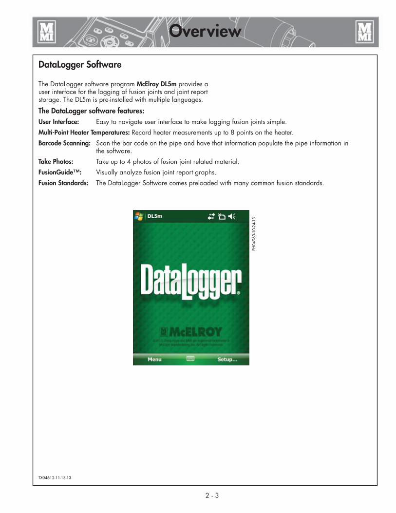
The DataLogger software program McElroy DL5m provides a user interface for the logging of fusion joints and joint report storage. The DL5m is pre-installed with multiple languages.
The DataLogger software features:User Interface: Easy to navigate user interface to make logging fusion joints simple.
Multi-Point Heater Temperatures: Record heater measurements up to 8 points on the heater.
Barcode Scanning: Scan the bar code on the pipe and have that information populate the pipe information in the software.
Take Photos: Take up to 4 photos of fusion joint related material.
FusionGuide ™: Visually analyze fusion joint report graphs.
Fusion Standards: The DataLogger Software comes preloaded with many common fusion standards.
TX04612-11-13-13
2 - 3
Overview
PH04
963-
10-2
4-13

3 - 1
DataLogger® Vault™
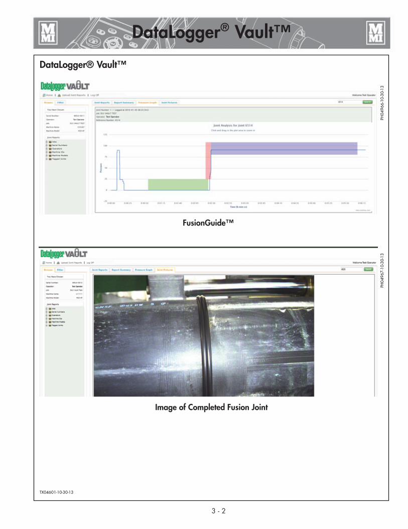
DataLogger® Vault™The DataLogger® Vault™ is a new software application from McElroy that provides joint data storage and analysis at no cost to users of the McElroy DataLogger version 3, 4, and 5. The DataLogger Vault is a secure, online application that allows users to view and analyze their joint data from almost any device, from almost any location. All that is needed is a device such as a PC, Mac, smartphone, tablet, etc. that has a browser and access to the Internet.
DataLogger 3, 4 and 5 data all reside together within the DataLogger Vault so it is not necessary to use multiple pieces of software to view joint data. And with features such as automatic grouping and sorting of joint data, custom tagging and filtering, it’s very easy to sort, view and analyze joint data by job, operator, machine, etc. without having to re-key data into a spreadsheet or database application.
If you do not already have access to the DataLogger Vault, we recommend creating your free account prior to fusing pipe with the DataLogger 5 so that you will be ready to take full advantage of the DataLogger 5’s advanced features.
To create your free DataLogger Vault account, and for more information (including complete instructions), visit: http://vault.mcelroy.com.
PH04
968-
10-3
0-13
Joint Information
DataLogger® Vault™
TX04601-10-30-13
PH04
966-
10-3
0-13
PH04
967-
10-3
0-13
3 - 2
DataLogger® Vault™
FusionGuide™
Image of Completed Fusion Joint

4 - 1
IntroductionThe DataLogger 5 features multipoint heater temperature entry, camera, GPS, barcode scanning, and FusionGuide™ visual fusion joint analysis.
The handheld computer comes with McElroy default settings and the DL5m software preloaded.
Menu items can be accessed by the tapping corresponding text label on the screen or by pushing the buttons on the keypad. For instance to access the Settings... menu item, push the Left Soft Key below the word Menu to reveal the DL5 menu then use the Up/Down Keys to navigate to Settings... then push Enter:
Access to program settings and logging starts from the main screen:
Below the DataLogger logo on the main screen, the current Vault account user is displayed.
When connected to the internet and an update is available for the software, an update software box will appear above the DataLogger logo on the main screen. Press the update software box to download and install the software update.
TX04602-12-02-14
Operation
PH05
324-
12-0
3-14
PH05
325-
12-0
3-14
Left Soft Key Right Soft Key
Arrow Pad
Enter Button

4 - 2
Operation
Main Menu1) English - When a language other than English is used and the
“Toggle to English” feature is enabled, this menu item toggles the display language to English.
2) DataLogger ® Vault™... - Change the current Vault account to send joint reports to. View joint reports stored on the handheld computer. Send joint reports from the handheld computer to the DataLogger Vault.
a) Account... - A DataLogger Vault account is required to automatically send joint reports. Go to http://vault.mcelroy.com and create a new account.
PH05
326-
12-0
3-14
PH05
327-
12-0
3-14
PH05
328-
12-0
3-14
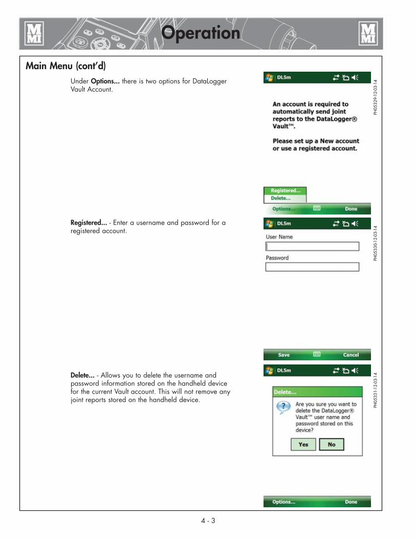
Main Menu (cont’d) Under Options... there is two options for DataLogger
Vault Account.
Registered... - Enter a username and password for a registered account.
Delete... - Allows you to delete the username and password information stored on the handheld device for the current Vault account. This will not remove any joint reports stored on the handheld device.
PH05
329-
12-0
3-14
PH05
330-
12-0
3-14
PH05
331-
12-0
3-14
4 - 3
Operation

Main Menu (cont’d) b) Joint Reports... - Displays the joint reports not sent and
sent to the DataLogger Vault.
Not sent to DataLogger® Vault™ - Lists the joint reports not sent to the Vault. If connected to the internet, the reports are sent automatically and not display any reports.
If joint reports are listed here, they can be viewed and appended and when connected to the internet sent to the Vault using the Send Reports... option.
Sent to DataLogger® Vault™ - List the joint reports sent to the Vault. Select a joint report to view the report and append the report.
At the end of the list there is an option to delete all the sent joint reports.
PH05
332-
12-0
3-14
PH05
333-
12-0
3-14
PH05
334-
12-0
3-14
4 - 4
Operation

4 - 5
Operation
Main Menu (cont’d) c) Send Reports... - When connected to the internet, send
all joint reports not sent to the Vault.
The handheld device must be logged into a DataLogger Vault account to be able to send reports.
PH05
337-
12-0
3-14
PH05
336-
12-0
3-14

Main Menu (cont’d)3) Tools… - Supporting utilities:
a) Update Software: DL5m software can be downloaded directly to the device for installation when Internet connection is available via wireless connection or Mobile Device Center.
b) Copy Report Files: Report files can be copied onto an SD card or USB drive attached to the optional adapter/cable. Contact your distributor about these options.
c) Reset Computer: Can be used if the device needs to be reset to correct an issue such as WiFi connection.
d) Help: Displays information about the Tools.
4) GPS Status… - Displays GPS information such as satellite count, signal strength, coordinates, etc.
5) Settings... - Change program settings:
a) Display language: selects language from the languages installed in the software.
b) Pressure units: psi, bar, kg/cm², MPa
c) Temperature units: °F, °C
6) About... - Display the software and firmware version, copyright information, computer serial number and pressure calibration date and time.
7) Exit - Exit the DL5m software.TX04603-12-04-14
PH05
326-
12-0
3-14
4 - 6
Operation
Setup to Log a Joint
1) OperatorFrom the main screen, tap Setup... or push the Right Soft Key to begin.
Always make sure the time and date are correct before making a joint. If time and date need adjustment, tap Change Date and Time.
Use the stylus to activate the onscreen keyboard by tapping the keyboard symbol.
Operator ID and Job # can be letters or numbers up to 30 characters each.
Joint # is digits-only, and it auto-increments after each completed joint.
Tap Next > > or push the Right Soft Key to setup machine, fusion type, and specification.
PH04
938-
10-1
6-13

4 - 7
Operation
Setup to Log a Joint (cont'd)
2) MachineEnter machine ID using the stylus and onscreen keyboard.
Select a machine model or choose Unlisted to enter a machine number and piston area.
Select a fusion type: Butt Fusion, Sidewall, or Dual Containment.
Select a fusion standard or specification.
Common specifications come preloaded: ASTM, ISO, UK, or DVS.
An Other selection allows for generic fusion calculation not based on an industry standard.
Tap Next >> to enter interfacial pressure..
3) IFPWhen the ASTM fusion standard is selected, the interfacial pressure (IFP) can be varied between 60psi and 90psi using the up/down arrow keys on the keypad.
Tap Next >> to enter pipe material and size information.
4) PipeManually select a pipe material from the list or enter an “Unlisted” material.
Enter pipe size and select the corresponding units. These numbers affect the fusion parameter calculations.
Tap “Next >>” to enter optional Notes (Step 5) about the joint.
OR
Use the barcode scanner on pipe with manufacturer stamped barcode.
Select the Scan Barcode option by tapping the selection or push the Enter key in the middle of the keypad.
PH04
939-
10-1
6-13
PH04
940-
10-1
6-13
PH04
941-
10-1
6-13

4 - 8
Operation
Setup to Log a Joint (cont'd)
4a) Pipe - Scan BarcodeWith barcode scanning option selected, tap the finger icon near the bottom of the screen or push the Enter Key in the middle of the keypad to activate the laser scanner
Do not stare into beam of the laser. Damage to eyes could occur. Point the laser only at the object you are scanning.
If the scanner times out, push the Enter Key to reactive it.
Point the red laser beam at the barcode to capture it.
Once the barcode is successfully scanned, detail pipe information from the barcode is displayed in the order of pipe size, manufacturer, lot number, production date, material, type, and the scanned barcode characters.
Tap Next >> to enter optional Notes about the joint.
5) Notes (Optional)Enter notes about the joint (optional)
More characters can be appended after the joint is made.
(The use of the stylus is not required after this screen)
Tap Next >> to take photo (optional)
PH04
942-
10-1
6-13
PH04
943-
10-1
6-13
PH04
614-
2-13
-12

Setup to Log a Joint (cont'd)
6) PhotosUp to 2 photos may be taken before the pipe is fused. The remaining unused photos can be taken after the pipe is fused for a total of 4 photos for each fusion joint. These photos can be taken to show pipe alignment, face off, job site setup, or anything related to the pipe fusion.
To take a photo, push the Enter Key in the middle of the keypad or tap on the Camera icon near the bottom of the screen. This will activate the camera.
To take a photo, first point the top of the device at the subject, then press the Quick Launch Key at the bottom right corner of the keypad to focus on the subject. A green focusing rectangle will appear on the screen.
Once focused, push the Enter Key in the middle of the keypad to capture the photo.
If GPS signal is available, photos will be stamped with GPS coordinates, and the red “Acquiring GPS Fix…” message will turn into the green “GPS Ready” message near the top left corner of the screen.
NOTE: Camera settings are optimized for this application, so please do not adjust them.
Once the photo is captured, tap Back or the Left Soft Key to exit the Camera feature.
PH04
944-
10-1
6-13
PH04
945-
10-1
6-13
PH04
614-
2-13
-12
4 - 9
Operation

4 - 10
Operation
Setup to Log a Joint (cont'd)In the viewing screen, the photo can be zoomed in and out using the Magnifier icon.
IMPORTANT: GPS coordinates will be stamped at the lower left corner of the photo if GPS signal is available.
A new photo can be taken to replace the current photo by tapping the Camera icon or pushing the Enter Key in the middle of the keypad.
To remove or delete the photo so that it will not be recorded in the report, tap the Trash Can icon.
When done, tap Next >> or the Right Soft Key to measure drag.
If one photo is taken, a second photo screen will appear to allow taking an optional second photo for the report.
7) Drag PressureFollow drag pressure measurement procedures from the fusion machine operator’s manual.
Press the Right Soft Key to select Set Drag.
Use the Up/Down arrow keys to select the default 30 psi drag pressure or the measured and displayed pressure at the top of the screen.
Press the Enter key to register the intended drag pressure.
Tap Next >> to review the recommended fusion pressures and times and prepare machine to fuse pipe.
8) PreparationReview the recommended fusion pressures and times and prepare machine to fuse pipe.
This example shows ASTM specified nominal pressures, minimum cycle times, bead size after heat soaking the pipe, and maximum carriage open/close time for heater removal.
Tap Next >> to record heater temperature.
PH04
947-
10-1
6-13
PH04
615-
2-13
-12
PH04
617-
2-13
-12

4 - 11
Operation
Setup to Log a Joint (cont’d)
9) Heater8 Heater points can be recorded, 4 from each side of the heater.
Select a point on the heater and measure the temperature. Use the Up/Down Arrow Key to adjust the number (425 in the example) in the box near the lower right corner of the screen to the measured temperature.
Tap the corresponding box, for instance A1, to place the number in the box.
Optionally, measure and record more points on the heater using the above procedure.
To remove a number, tap the X near the lower right corner of the screen. Make sure the checkbox is marked with a check symbol (), and then tap on the box with the number to delete.
Tap Next >>
10) Ready to LogMake sure pipe ends are properly faced and heater is securely placed in the fusion machine between two pipe ends.
If necessary, press << Back to review or change settings on previous screens or tap Cancel to go back to the main DataLogger screen.
Press the Right Soft Key then Enter or tap Log... and then Start to begin logging then close the carriage to heat pipe.
PH04
948-
10-1
6-73
PH04
949-
10-1
6-13
PH04
619-
2-13
-11

4 - 12
Operation
Setup to Log a Joint (cont’d)
11) Logging...While logging a joint, the number of data points logged is displayed, along with the elapsed time, the current pressure reading, the various pressures, times, bead size, and open/close time.
A stop watch at the lower left corner can be used to time the various fusion cycles. Pressing the Left Soft Key or tapping Reset SW resets the stopwatch count.
GPS activity is shown at the lower right corner of the screen. “Acquiring GPS Fix…” appears when the handheld computer is seeking GPS signal, and actual coordinates replaces the text when GPS signal is acquired.
At the end of the fusion process, press the Right Soft Key then Enter or tap Stop then Yes to stop logging.
PH04
950-
10-1
6-13

4 - 13
Operation
Review Joint Report
Joint ReportReview the joint report before proceeding to the next fusion joint.
Joint Report page 1 is displayed when logging is completed. This page shows:
1. Date and Time2. Joint Number3. Job Number4. Operator5. Machine ID6. Model of Machine7. Piston Area of Machine8. Pipe: Type with size (barcode data if recorded)
Tap Next >> or press the Right Soft Key to go to page 2.
Tap << End or press the Left Soft Key to go back to the main DataLogger screen.
Joint Report page 2 is displayed. This page shows:
9. Fusion Type with Standard used10. Heater Temperature Range11. External Probe Measurement (up to 8 temperatures)12. Specification Pressures and Times13. Recorded Drag Pressure14. Interfacial Pressure
Tap Next >> or press the Right Soft Key to go to page 3.
Tap << Back or press the Left Soft Key to go back to the previous page.
Joint Report page 3 is displayed. This page shows:
15. Computer Serial Number16. Software and Version Number17. DataLogger Serial Number18. Pressure Sender Firmware Version19. Calibration Date20. GPS CoordinatesUp to 3 GPS coordinates can be recorded. The first set of coordinates is recorded when logging starts.To add new GPS coordinates, tap the GPS icon on the screen or push Enter in the middle of the keypad and follow the instructions on the screen.
To cancel recording GPS when “Acquiring GPS Fix…” is displayed, tap Next >>.
To append GPS coordinates at a later time, go to the “Append GPS Coordinates” section of this manual.
Tap Next >> or press the Right Soft Key to go to page 4.
Tap << Back or press the Left Soft Key to go back to the previous.
PH04
951-
10-1
6-13
PH04
952-
10-1
6-13
PH04
953-
10-1
6-13

4 - 14
Operation
Review Joint Report (cont’d)Joint Report Notes page allows viewing of the notes entered prior to the joint being made, and the ability to append more notes to the joint report.
To append more notes, tap the Append Notes... button on the screen.
Tap Next >> to view the Front-end Plot
Tap << Back or press the Left Soft Key to go back to the previous page.
The top box is read-only and it shows notes entered previously.
The bottom box is where characters for the new notes can be entered. A total of 1000 characters are allowed per joint report. New notes entered in this box will be appended to notes in the read-only box above.
Use the scroll bar on the right side of the text boxes to scroll through long messages.
After notes are entered, tap Save or press the Left Soft Key to save the new notes.
Otherwise tap Cancel to discard the new notes and exit the Append Notes screen without saving.
PH04
626-
2-13
-12
PH04
627-
2-13
-12
4 - 15
Operation
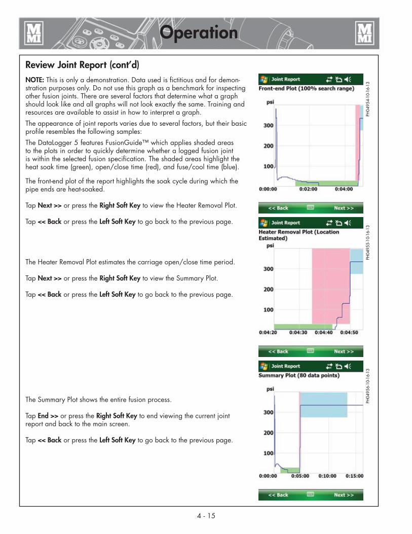
Review Joint Report (cont’d)NOTE: This is only a demonstration. Data used is fictitious and for demon-stration purposes only. Do not use this graph as a benchmark for inspecting other fusion joints. There are several factors that determine what a graph should look like and all graphs will not look exactly the same. Training and resources are available to assist in how to interpret a graph.
The appearance of joint reports varies due to several factors, but their basic profile resembles the following samples:
The DataLogger 5 features FusionGuide™ which applies shaded areas to the plots in order to quickly determine whether a logged fusion joint is within the selected fusion specification. The shaded areas highlight the heat soak time (green), open/close time (red), and fuse/cool time (blue).
The front-end plot of the report highlights the soak cycle during which the pipe ends are heat-soaked.
Tap Next >> or press the Right Soft Key to view the Heater Removal Plot.
Tap << Back or press the Left Soft Key to go back to the previous page.
The Heater Removal Plot estimates the carriage open/close time period.
Tap Next >> or press the Right Soft Key to view the Summary Plot.
Tap << Back or press the Left Soft Key to go back to the previous page.
The Summary Plot shows the entire fusion process.
Tap End >> or press the Right Soft Key to end viewing the current joint report and back to the main screen.
Tap << Back or press the Left Soft Key to go back to the previous page.
PH04
954-
10-1
6-13
PH04
955-
10-1
6-13
PH04
956-
10-1
6-13

4 - 16
Operation
Review Joint Report (cont’d)Photos taken prior to logging are part of the report and cannot be re-moved.
GPS coordinates is tagged at the lower left corner of the photo if available.
Tap the Magnifier icon to zoom in on the photo.
Tap Next >> when done reviewing the photo.
A second photo taken prior to logging is part of the report and cannot be deleted.
GPS coordinates is tagged at the lower left corner of the photo if available.
Tap the Magnifier icon to zoom in on the photo.
Tap Next >> when done reviewing the photo.
A total of 4 photos can be included in a joint report.
To add new photo after the joint is made, tap the Camera icon near the bottom of the screen, or push the Enter Key in the middle of the keypad to activate the Camera.
PH04
957-
10-1
6-13
PH04
958-
10-1
6-13
PH04
959-
10-1
6-13

4 - 17
Operation
Review Joint Review (cont’d)Once back at the main screen, you may prepare to make another fusion joint by pressing the Right Soft Key or tapping Setup...
Data from the previous joint will be carried over to reduce data entry for the next joint saving time at the jobsite.
Time and date are automatically updated for the next joint. Joint number is also automatically incremented after each joint.
Use the scroll bar on the side to review more data about the next joint.
Press the Right Soft Key to select Yes and start a new joint.
Press the Left Soft Key to select Cancel to go back to main screen.
Tap No to enter new data for the next joint.
TX04604-10-30-13
PH04
963-
10-2
4-13
PH04
960-
10-1
6-13

Append GPS CoordinatesAfter a fusion joint is completed, it may be necessary to append the GPS coordinates in that report if that fusion joint has moved to a different location.
To append the GPS coordinates:
1) Go to DataLogger® Vault™... on the main menu on the main screen and select Joint Reports....
2) Select the joint report you wish to append from the list on the handheld computer.
3) Navigate through the joint report to Page 3 of the joint report.
To add new GPS coordinates, tap the GPS icon on the bottom of the screen or push Enter in the middle of the keypad and follow the instructions on the screen.
4) There will be two warning dialog boxes asking if you want to proceed with recording new GPS coordinates.
5) Up to 3 GPS coordinates can be recorded. The first set of coordinates is recorded when logging starts.
If there is no GPS icon at the bottom of Page 3 of the joint report, then all 3 of the GPS coordinates have been used.
TX04763-12-04-14
PH05
326-
12-0
3-14
PH05
335-
12-0
3-14
PH04
972-
11-1
4-13
PH04
973-
11-1
4-13
PH04
974-
11-1
4-13
PH04
975-
11-1
4-13
4 - 18
Operation
1
2
3
4
5

5 - 1
Transfer Joint Reports
Transfer Joint Reports to PCIntroductionMcElroy DataLogger 5 joint reports can be viewed and analyzed on the DataLogger Vault (http://vault.mcelroy.com). Joint reports are transferred from the DataLogger 5 to your PC using the Microsoft® Windows® Mobile Device Center (for Windows® 8, Windows® 7 or Vista®) or Microsoft® ActiveSync® (for Windows® XP).
Microsoft Software (for transferring joint reports)There are different versions of Microsoft® Windows® operating systems in circulation: Windows® XP, 32-bit and 64-bit versions of Windows® Vista®, Windows® 7 and Windows® 8. First, find out which operating system your computer runs and then visit http://www.mcelroy.com/fusion/support/to download the corresponding Microsoft® software.
Save and then run your downloaded Microsoft® software and follow the installation instructions. Installations may take a few minutes, so it is best to wait and make sure installation is com-plete before moving on. “Device Not Found” error near the end of the installation can be ignored because the operating system is looking for a device that is not yet connected to the PC.
PH04
969-
11-1
2-13
5 - 2
Transfer Joint Reports
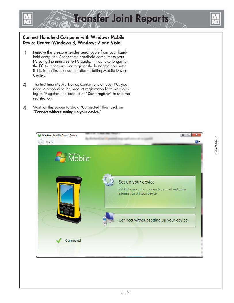
Connect Handheld Computer with Windows Mobile Device Center (Windows 8, Windows 7 and Vista)
1) Remove the pressure sender serial cable from your hand-held computer. Connect the handheld computer to your PC using the mini-USB to PC cable. It may take longer for the PC to recognize and register the handheld computer if this is the first connection after installing Mobile Device Center.
2) The first time Mobile Device Center runs on your PC, you need to respond to the product registration form by choos-ing to “Register” the product or “Don’t register” to skip the registration.
3) Wait for this screen to show “Connected” then click on “Connect without setting up your device.”
PH04
632-
1-24
-12
5 - 3
Transfer Joint Reports
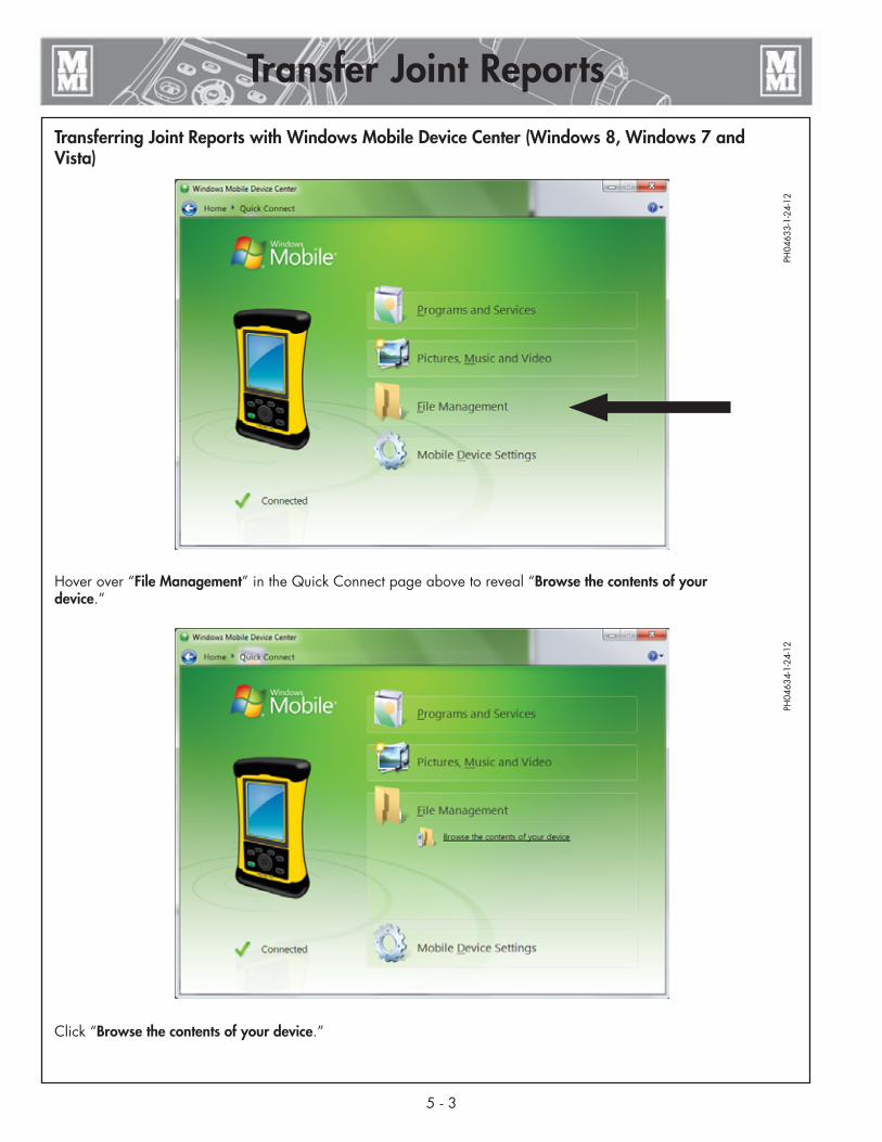
Transferring Joint Reports with Windows Mobile Device Center (Windows 8, Windows 7 and Vista)
Hover over “File Management” in the Quick Connect page above to reveal “Browse the contents of your device.”
Click “Browse the contents of your device.”
PH04
633-
1-24
-12
PH04
634-
1-24
-12

5 - 4
Transfer Joint Reports
Transferring Joint Reports with Windows Mobile Device Center (Windows 8, Windows 7 and Vista)
Double click on the device icon in the explorer window under “Computer\Trimble Navigation Ltd. Nomad”
Double click on the “My Documents” folder and look for the “Joint Reports” folder
PH04
635-
1-24
-12
PH04
636-
1-24
-12

Transferring Joint Reports with Windows Mobile Device Center (Windows 8, Windows 7 and Vista)
Right-click on the “Joint Reports” folder and then click “Copy”.
Find a clean spot on your Computer’s desktop, right-click and then paste the entire Joint Reports folder on your desktop.
You may append today’s date to the folder name, for instance “Joint Reports 2011-11-15”.
Now you have successfully copied the entire Joint Reports folder on to your desktop PC. [Note: Once you are sure you have secured the joint reports on your PC and on an optional external or secondary storage, you may delete the folder on the handheld computer.]
Your joint reports folder may look like this with a list of joint reports:
After you transfer your data to the PC, you can easily upload your data to the DataLogger Vault for review, analysis, and storage. See the “DataLogger Vault” section of this manual for more information.
5 - 5
Transfer Joint Reports
PH04
637-
1-24
-12
PH04
961-
10-1
7-13

Transferring Joint Reports with Microsoft ActiveSync for Windows XP1) Remove the pressure sender serial cable from your handheld computer. Connect the handheld to your PC using
the mini-USB to PC cable. It may take longer for the PC to recognize and register the handheld computer if this is the first connection after installing Microsoft ActiveSync.
2) Wait for this screen to show and then click Cancel
3) Click the Explore button below when ActiveSync shows “Connected”
Transfer Joint Reports
5 - 6
PH04
655-
1-24
-12
PH04
656-
1-24
-12

5 - 7
Transferring Joint Reports with Microsoft ActiveSync for Windows XP4) Right click on the “Joint Reports” folder and then click “Copy”.
Find a clean spot on your computer’s desktop, right click and then paste the entire Joint Reports folder on your desktop.
You may append today’s date to the folder name, for instance “Joint Reports 2011-11-15”.
Now you have successfully copied the entire Joint Reports folder on to your desktop PC.
Note: Once you are sure you have secured the joint reports on your PC and on an optional external or secondary storage, you may delete the folder on the handheld computer.
After you transfer your data to the PC, you can easily upload your data to the DataLogger Vault for review, analysis, and storage. See the “DataLogger Vault” section of this manual for more information.
TX04605-11-14-13
Transfer Joint Reports
PH04
657-
1-24
-12

6 - 1
Maintenance
Usage and Care
Pressure Sender cordThe coiled cord, which connects the pressure sender to the handheld computer, has screw connectors on both ends. If the cord is damaged it is easily replaced by unscrewing both ends and installing a new cord.
Quick DisconnectThis DataLogger® uses an improved quick disconnect on the pressure sender. It is designed to seal reliably but not trap pressure in the line. It can be connected under pressure if necessary. To use this unit on older fusion machines you will need Fusion Machine Adapter Kit ADL6001. Remove the QD and fittings on the carriage manifold TXA port and replace them with the elbow and QD in the kit.
Pressure SenderThe pressure sender is calibrated at McElroy Manufacturing, Inc. Its calibration should be checked annually to main-tain factory quality.
Handheld ComputerKeep the handheld computer clean especially around the connections, camera, barcode scanner, and keypad. Keep the screen clean and free of debris.
TX04610-11-12-13

No User Serviceable PartsNOTICE: There are no parts of the DataLogger® that can be repaired by the user. Do not try to open the unit. Any attempt to open the unit can affect the weatherproofing and can damage the unit.
TX04399-2-29-12
Maintenance
6 - 2
CalibrationPressure sender must be sent to McElroy or Authorized Service Center every year for calibration to ensure accuracy.
A backup pressure sender may be kept on hand to minimize down time.
TX04400-2-29-12
Replacement Parts and AccessoriesFor replacement parts and accessories, visit the McElroy Parts Finder at: http://fusion.mcelroy.com/parts/exec
Enter your Serial Number or Model/Part Number to find parts and accessories for your equipment.
TX04611-11-12-13
7 - 1
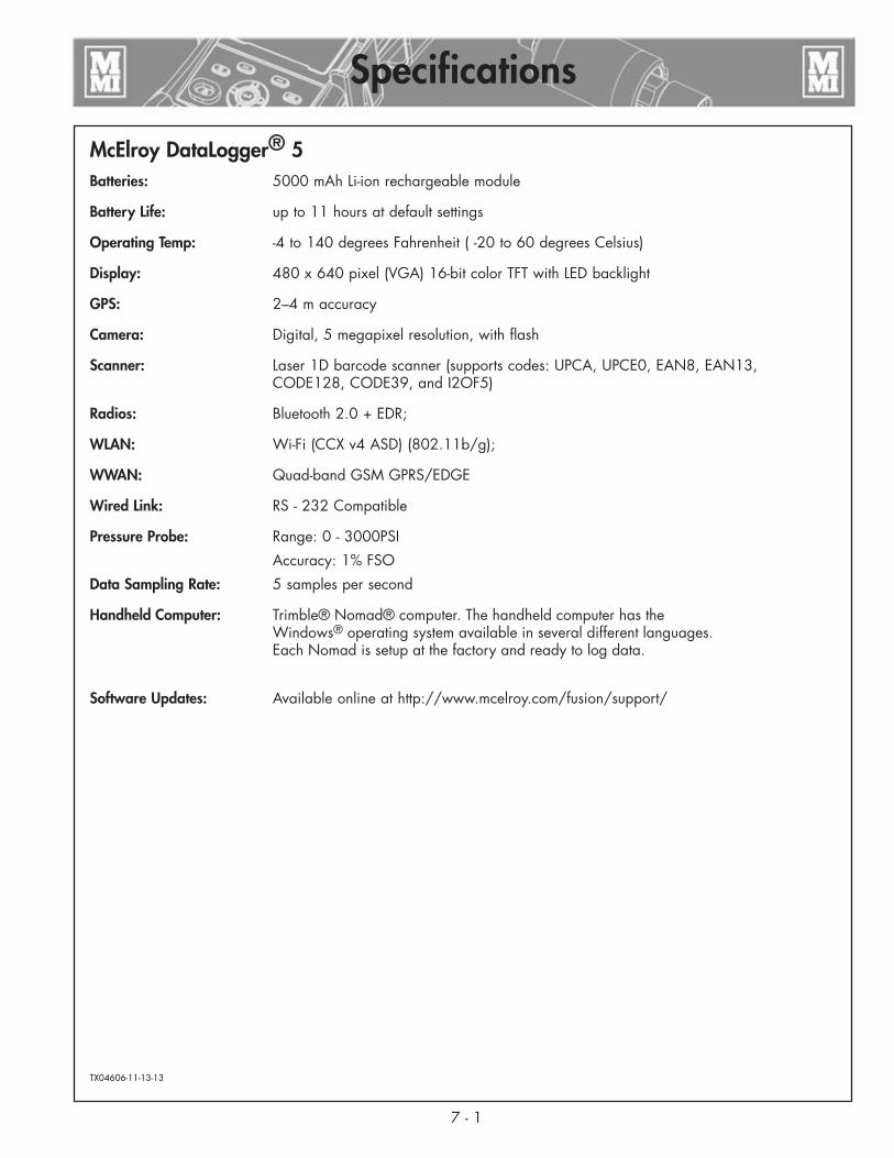
McElroy DataLogger® 5
Batteries: 5000 mAh Li-ion rechargeable module
Battery Life: up to 11 hours at default settings
Operating Temp: -4 to 140 degrees Fahrenheit ( -20 to 60 degrees Celsius)
Display: 480 x 640 pixel (VGA) 16-bit color TFT with LED backlight
GPS: 2–4 m accuracy
Camera: Digital, 5 megapixel resolution, with flash
Scanner: Laser 1D barcode scanner (supports codes: UPCA, UPCE0, EAN8, EAN13, CODE128, CODE39, and I2OF5)
Radios: Bluetooth 2.0 + EDR;
WLAN: Wi-Fi (CCX v4 ASD) (802.11b/g);
WWAN: Quad-band GSM GPRS/EDGE
Wired Link: RS - 232 Compatible
Pressure Probe: Range: 0 - 3000PSI
Accuracy: 1% FSO
Data Sampling Rate: 5 samples per second
Handheld Computer: Trimble® Nomad® computer. The handheld computer has the Windows® operating system available in several different languages. Each Nomad is setup at the factory and ready to log data.
Software Updates: Available online at http://www.mcelroy.com/fusion/support/
TX04606-11-13-13
Specifications


About this manual . . .McElroy Manufacturing continually strives to give customers the best quality products available. This manual is printed with materials made for durable applications and harsh environments.
This manual is waterproof, tear resistant, grease resistant, abrasion resistant and the bonding quality of the printing ensures a readable, durable product.
The material does not contain any cellulose based materials and does not contribute to the harvesting of our forests, or ozone-depleting constituents. This manual can be safely disposed of in a landfill and will not leach into ground water.
TX001660-8-19-99


