CONTENTS 2 Contents 1 Project Summary 6 2 Significance and Background 7 2.1 Deformation & Fracture: the Key to First Wall Survival ................ 7 2.1.1 Lower operating temperature limits ....................... 8 2.1.2 Upper operating temperature limits ....................... 9 2.1.3 Operating Temperature Windows ........................ 10 2.2 The Multiscale Modeling Approach as a New Paradigm ................ 11 3 Research Objectives 14 4 Research Plan 16 4.1 KMC & Rate Theory Modeling of Microstructure Evolution ............. 16 4.1.1 Kinetic Monte Carlo Simulation of Defects ................... 16 4.1.2 Elastic Interactions between Point Defects .................... 18 4.1.3 Implementation of KMC Algorithm ....................... 18 4.1.4 Diffusion of Glissile SIA Clusters ......................... 20 4.1.5 Accumulation of Radiation Damage ....................... 20 4.1.6 The Role of Advanced Rate Theory ....................... 22 4.1.7 Radiation-Induced Phase Transitions ...................... 23 4.2 Modeling Plasticity of Irradiated Materials ....................... 24 4.2.1 Radiation Hardening & Plastic Instabilities ................... 24 4.2.2 A Self-consistent Meso-mechanics Variational Formulation ........... 25 4.3 Modeling Fracture Processes ................................ 27
Transcript
CONTENTS 2
Contents
1 Project Summary 6
2 Significance and Background 7
2.1 Deformation & Fracture: the Key to First Wall Survival . . . . . . . . . . . . . . . . 7
Understanding the effects of fusion neutron irradiation on the mechanical properties of structuralmaterials is undoubtedly pivotal to the successful development of reliable, safe and economicalfusion energy sources. Recent advances in computer modeling and simulations of the mechanicsof materials at the nano- and micro- scales are providing unprecedented opportunities for thefusion materials program. The Multiscale Modeling of Materials (MMM) approach, which relieson a systematic, yet rigorous reduction of the degrees of freedom at natural length scales is acornerstone of the present proposal. Connections between such scales are achieved either by aparameterization or a coarse-graining procedure. Parameters that describe the system at a lowerlength scale are obtained from computer simulations, verified experimentally, and passed on toupper scales. The main motivation behind this proposal is to provide the science underpinnings forthe design of radiation-resistant structural materials, and to plan for meaningful experiments thatcan be understood through physical models of deformation and fracture phenomena.
The objective of this proposal is to develop a range of hierarchical models for the post-elasticdeformation, fracture and failure of fusion structural materials. The proposed multiscale modelingapproach is based on rigorous mathematical, physical, and computational methods at the fore-front of computational materials science. At the fundamental and smallest length scale (nm-µm),we plan to continue our development of advanced rate theory and Monte Carlo approaches tomodel microstructure evolution, non-equilibrium phase transformations, and dislocation-defect in-teractions. Microscopic and mesoscopic models of radiation hardening, ductile-to-brittle-transition,post-elastic deformation, plastic instabilities, and fracture processes will be based on DislocationDynamics (DD) and Grain Growth Dynamics (GGD) . At the continuum level, we will focus onmodeling fracture and failure mechanisms for Virtual Integrated Testing (VISTA), and for under-standing the limits of both materials-by-design versus structural component design. We will usemeshfree, parallel FEM, and coupled FEM-DD methodologies to predict failure modes, lifetimesand reliability of critical First Wall/ Blanket components. The proposed research is strongly cou-pled with the U.S. national experimental program to ascertain and verify the range of investigatedphenomena. The following tasks are proposed for the five-year duration of the project:
1. KMC & Rate Theory Modeling of Microstructure Evolution;
2. Radiation-Induced Phase Transitions;
3. Dislocation-Defect Interaction Mechanisms;
4. Radiation Hardening & Plastic Instabilities;
5. High-Temperature Helium Embrittlement;
6. Modeling Fracture Processes;
7. Modeling the Ductile-to-Brittle Transition;
8. Participation and co-development of VISTA: a Virtual Integrated Test Assembly;
9. Development of The Digital Fusion Materials Database & Constitutive Equations.
2 SIGNIFICANCE AND BACKGROUND 7
2 Significance and Background
2.1 Deformation & Fracture: the Key to First Wall Survival
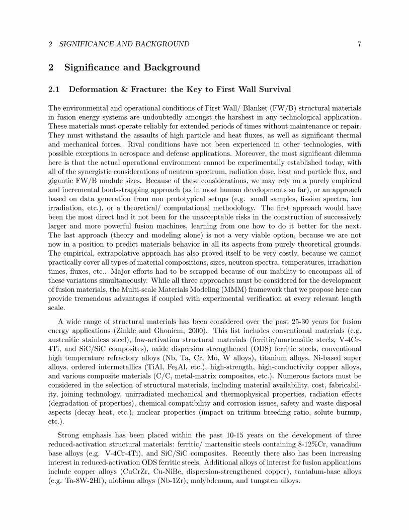
The environmental and operational conditions of First Wall/ Blanket (FW/B) structural materialsin fusion energy systems are undoubtedly amongst the harshest in any technological application.These materials must operate reliably for extended periods of times without maintenance or repair.They must withstand the assaults of high particle and heat fluxes, as well as significant thermaland mechanical forces. Rival conditions have not been experienced in other technologies, withpossible exceptions in aerospace and defense applications. Moreover, the most significant dilemmahere is that the actual operational environment cannot be experimentally established today, withall of the synergistic considerations of neutron spectrum, radiation dose, heat and particle flux, andgigantic FW/B module sizes. Because of these considerations, we may rely on a purely empiricaland incremental boot-strapping approach (as in most human developments so far), or an approachbased on data generation from non prototypical setups (e.g. small samples, fission spectra, ionirradiation, etc.), or a theoretical/ computational methodology. The first approach would havebeen the most direct had it not been for the unacceptable risks in the construction of successivelylarger and more powerful fusion machines, learning from one how to do it better for the next.The last approach (theory and modeling alone) is not a very viable option, because we are notnow in a position to predict materials behavior in all its aspects from purely theoretical grounds.The empirical, extrapolative approach has also proved itself to be very costly, because we cannotpractically cover all types of material compositions, sizes, neutron spectra, temperatures, irradiationtimes, fluxes, etc.. Major efforts had to be scrapped because of our inability to encompass all ofthese variations simultaneously. While all three approaches must be considered for the developmentof fusion materials, the Multi-scale Materials Modeling (MMM) framework that we propose here canprovide tremendous advantages if coupled with experimental verification at every relevant lengthscale.
A wide range of structural materials has been considered over the past 25-30 years for fusionenergy applications (Zinkle and Ghoniem, 2000). This list includes conventional materials (e.g.austenitic stainless steel), low-activation structural materials (ferritic/martensitic steels, V-4Cr-4Ti, and SiC/SiC composites), oxide dispersion strengthened (ODS) ferritic steels, conventionalhigh temperature refractory alloys (Nb, Ta, Cr, Mo, W alloys), titanium alloys, Ni-based superalloys, ordered intermetallics (TiAl, Fe3Al, etc.), high-strength, high-conductivity copper alloys,and various composite materials (C/C, metal-matrix composites, etc.). Numerous factors must beconsidered in the selection of structural materials, including material availability, cost, fabricabil-ity, joining technology, unirradiated mechanical and thermophysical properties, radiation effects(degradation of properties), chemical compatibility and corrosion issues, safety and waste disposalaspects (decay heat, etc.), nuclear properties (impact on tritium breeding ratio, solute burnup,etc.).
Strong emphasis has been placed within the past 10-15 years on the development of threereduced-activation structural materials: ferritic/ martensitic steels containing 8-12%Cr, vanadiumbase alloys (e.g. V-4Cr-4Ti), and SiC/SiC composites. Recently there also has been increasinginterest in reduced-activation ODS ferritic steels. Additional alloys of interest for fusion applicationsinclude copper alloys (CuCrZr, Cu-NiBe, dispersion-strengthened copper), tantalum-base alloys(e.g. Ta-8W-2Hf), niobium alloys (Nb-1Zr), molybdenum, and tungsten alloys.
2 SIGNIFICANCE AND BACKGROUND 8
It has been established, especially during the past decade, that the most important consid-erations in structural material selection, increasing the useful operating temperature-dose designwindow, and component lifetime or reliability are all governed by deformation and fracture phe-nomena. In the following, we give a brief analysis of the most limiting mechanical properties basedon our earlier work (Zinkle and Ghoniem, 2000).
2.1.1 Lower operating temperature limits
The lower temperature limits for FW/B structural materials (i.e. excluding copper alloys) arestrongly influenced by radiation effects. For body-centered cubic (BCC) materials such as ferritic-martensitic steels and the refractory alloys, radiation hardening at low temperatures can lead toa large increase in the Ductile-To-Brittle-Transition-Temperature (DBTT)(Hishinuma, Kohyama,Klueh, Gelles, Dietz and Ehrlich, 1998; Cox and Wiffen, 1973; Klueh and Alexander, 1995; Odetteand Lucas, 1983; Rieth, Dafferner and Rohrig, 1998). For SiC/SiC composites, the main con-cerns at low temperatures are radiation-induced amorphization (with an accompanying volumetricswelling of ∼11%) (Snead, Zinkle, Hay and Osborne, 1998) and radiation-induced degradation ofthermal conductivity. The radiation hardening in BCC alloys at low temperatures (0.3TM ) is gen-erally pronounced, even for doses as low as ∼1 dpa (Rieth et al., 1998; Wiffen, 1973; Maksimkin,1995; Snead, Zinkle, Alexander, Rowcliffe, Robertson and Eatherly, 1997; Zinkle and et al., 1998).The amount of radiation hardening typically decreases rapidly with irradiation temperature above0.3 TM , and radiation-induced increase in the DBTT may be anticipated to be acceptable at tem-peratures above ∼0.3TM . A Ludwig-Davidenkov relationship (Cox and Wiffen, 1973; Odette andLucas, 1983) between hardening and embrittlement was used to estimate the DBTT shift withincreased irradiation dose. In this model, brittle behavior occurs when the temperature dependentyield strength exceeds the cleavage stress. It is worth noting that operation at lower temperatures(i.e. within the embrittlement temperature regime) may be allowed for some low-stress fusionstructural applications (depending on the value of the operational stress intensity factor relative tothe fracture toughness).
Numerous studies have been performed to determine the radiation hardening and embrittlementbehavior of ferritic-martensitic steels. The hardening and DBTT shift are dependent on the detailedcomposition of the alloy. For example, the radiation resistance of Fe-9Cr-2WVTa alloys appears tobe superior (less radiation hardening) to that of Fe-9Cr-1MoVNb (Zinkle, Robertson and Klueh,1998a; Robertson, Shiba and Rowcliffe, 1997). The radiation hardening and DBTT shift appear toapproach saturation values following low temperature irradiation to doses above 1-5 dpa, althoughadditional high-dose studies are needed to confirm this apparent saturation behavior. At higherdoses under fusion conditions, the effects of He bubble accumulation on radiation hardening andDBTT need to be addressed. Experimental observations revealed brittle behavior (KIC ∼30 MPa-√m) in V-(4-5)%Cr-(4-5)%Ti specimens irradiated and tested at temperatures below 400C (Zinkle,
Snead, Rowcliffe, Alexander and Gibson, 1998b; Gruber, Galvin and Chopra, 1998). From acomparison of the yield strength and Charpy impact data of unirradiated and irradiated V-(4-5)%Cr-(4-5)%Ti alloys, brittle fracture occurs when the tensile strength is higher than 700 MPa.Therefore, 400C may be adopted as the minimum operating temperature for V-(4-5)%Cr-(4-5)%Tialloys in fusion reactor structural applications(Zinkle and et al., 1998). Further work is needed toassess the impact (if any) of fusion-relevant He generation rates on the radiation hardening andembrittlement behavior of vanadium alloys.
2 SIGNIFICANCE AND BACKGROUND 9
Very little information is available on the mechanical properties of irradiated W alloys. Tensileelongation of ∼ 0 have been obtained for W irradiated at relatively low temperatures of 400 and500C (0.18-0.21 TM ) and fluences of 0.5 − 1.5 × 1026 n/m2 (≺2 dpa in tungsten) (Wiffen, 1984;Steichen, 1976; Gorynin and et al., 1992). Severe embrittlement (DBTT ≥ 900C) was observed inun-notched bend bars of W and W-10%Re irradiated at 300C to a fluence of 0.5× 1026 n/m2 (≺1 dpa)(Krautwasser and Derz, 1976). Since mechanical properties data are not available for puretungsten or its alloys irradiated at high temperatures, an accurate estimate of the DBTT versusirradiation temperature cannot be made. The minimum operating temperature which avoids severeradiation hardening embrittlement is expected to be 900± 100C.
2.1.2 Upper operating temperature limits
The upper temperature limit for structural materials in fusion reactors may be controlled by fourdifferent mechanisms (in addition to safety considerations): Thermal creep, high temperature he-lium embrittlement, void swelling, and compatibility: corrosion issues. Void swelling is not antic-ipated to be significant in ferritic-martensitic steel (Gelles, 1996) or V-Cr-Ti alloys (Loomis andSmith, 1992) up to damage levels in excess of 100 dpa, although swelling data with fusion-relevantHe:dpa generation rates are needed to confirm this expectation and to determine the lifetime doseassociated with void swelling. The existing fission reactor database on high temperature (Mo, W,Ta) refractory alloys (e.g. (Wiffen, 1984)) indicates low swelling (≺2%) for doses up to 10 dpa orhigher. Radiation-enhanced recrystallization (potentially important for stress-relieved Mo and Walloys) and radiation creep effects (due to a lack of data for the refractory alloys and SiC) needto be investigated. Void swelling is considered to be of particular importance for SiC (and alsoCu alloys, which were shown to be unattractive fusion structural materials (Zinkle and Ghoniem,2000)).
An adequate experimental database exists for thermal creep of ferritic-martensitic steels (Shiba,Hishinuma, Tohyama and Masamura, 1997) and the high temperature (Mo, W, Nb, Ta) refractoryalloys (Goldberg, 1969; Conway, 1984; McCoy, 1986). Oxide-dispersion-strengthened ferritic steelsoffer significantly higher thermal creep resistance compared to ferritic-martensitic steels (Ukai,Nishida, Okuda and Yoshitake, 1998; Maziasz and et al., 1999), with a steady-state creep rateat 800C as low as 3 × 10⁻¹⁰ s−1 for an applied stress of 140 MPa (Maziasz and et al., 1999).The V-4Cr-4Ti creep data suggest that the upper temperature limit lies between 700 and 750C,although strengthening effects associated with the pickup of 200-500 ppm oxygen during testingstill need to be examined. The predicted thermal creep temperature limit for advanced crystallineSiC-based fibers is above 1000C (Youngblood, Jones, Morscher and Kohyama, 1997).
One convenient method to determine the dominant creep process for a given stress and temper-ature is to construct an Ashby deformation map (Ashby, 1972). Using the established constitutiveequations for grain boundary sliding (Coble creep), dislocation creep (power law creep) and self-diffusion (Nabarro-Herring) creep, the dominant deformation- mode regimes can be established(Zinkle and Ghoniem, 2000)
2 SIGNIFICANCE AND BACKGROUND 10
Figure 1: Operating temperature windows (based on radiation damage and thermal creep con-siderations) for refractory alloys, Fe-(8-9%)Cr ferritic-martensitic steel, Fe-13%Cr oxide dispersionstrengthened ferritic steel, Type 316 austenitic stainless steel, solutionized and aged Cu-2%Ni-0.3%Be, and SiC/SiC composites. The light shaded bands on either side of the dark bands representthe uncertainties in the minimum and maximum temperature limits.
2.1.3 Operating Temperature Windows
Figure (1) summarizes the operating temperature windows (based on thermal creep and radiationdamage considerations) for nine structural materials considered by Zinkle and Ghoniem (2000). Thetemperature limits for Type 316 austenitic stainless steel are also included for sake of comparison.In this figure, the light shaded regions on either side of the dark horizontal bands are an indicationof the uncertainties in the temperature limits. Helium embrittlement may cause a reduction inthe upper temperature limit, but sufficient data under fusion-relevant conditions are not availablefor any of the candidate materials. Due to a high density of matrix sinks, ferritic/martensiticsteel appears to be very resistant to helium embrittlement (Hishinuma et al., 1998; Schroeder andUllmaier, 1991). An analysis of He diffusion kinetics in vanadium alloys predicted that heliumembrittlement would be significant at temperatures above 700C (Ryazanov, Manichev and vanWitzenburg, 1996). As discussed in Subsection 2.1.1, the lower temperature limits in Figure (1) forthe refractory alloys and ferritic:martensitic steel are based on fracture toughness embrittlementassociated with low temperature neutron irradiation. An arbitrary fracture toughness limit of 30MPa-
√m was used as the criterion for radiation embrittlement. Further work is needed to deter-
mine the minimum operating temperature limit for oxide dispersion strengthened (ODS) ferriticsteel (Hishinuma et al., 1998). The value of 290 ± 40C used in Figure (1) was based on resultsfor HT-9 (Fe-12Cr ferritic steel) (Rowcliffe and et al., 1998). The minimum operating tempera-ture for SiC/SiC was based on radiation-induced thermal conductivity degradation, whereas theminimum temperature limit for CuNiBe was simply chosen to be near room temperature. The lowtemperature fracture toughness radiation embrittlement is not sufficiently severe to preclude using
2 SIGNIFICANCE AND BACKGROUND 11
copper alloys near room temperature (Alexander, Zinkle and Rowcliffe, 1999; Tatinen, Pyykkoen,Karjalainen-Roikonen, Singh and Toft, 1998), although there will be a significant reduction in strainhardening capacity as measured by the uniform elongation in a tensile test. The high temperaturelimit was based on thermal creep for all of the materials except SiC and CuNiBe. Due to a lack oflong-term (10,000 h), low-stress creep data for several of the alloy systems, a Stage II creep defor-mation limit of 1% in 1000 h for an applied stress of 150 MPa was used as an arbitrary criterionfor determining the upper temperature limit associated with thermal creep. Further creep dataare needed to establish the temperature limits for longer times and lower stresses in several of thecandidate materials.
2.2 The Multiscale Modeling Approach as a New Paradigm
Computational modeling of materials behavior is becoming a reliable tool of scientific investiga-tion, complementary to traditional theory and experimentation. The Multiscale Materials Modeling(MMM) approach reflects the realization that continuum and atomistic analysis methods are com-plementary. Understanding materials behavior acknowledges the dual nature of the structure ofmatter: being continuous when viewed at large length scales and being discrete when viewed atan atomic scale. At meso-scales (i.e. in between continuum and atomistic), continuum approachesbegin to break down, and atomistic methods reach inherent time and length-scale limitations.Mesoscopic simulation methods are developed to bridge the gap between length scale extremes.Recently, a number of factors may have led the scientific community to seriously consider theMMM approach as a reasonable strategy for understanding the mechanical behavior of materials,and hence as a potential approach to material system design.
The power of analytical theory lies in its ability to reduce the complex collective behavior of thebasic ingredients of materials (e.g. atoms and electrons, if one admits tight coupling between nucle-ons) into insightful relationships between cause and effect. For example, the relationship betweenthe magnitude of an externally applied force and the position of all atoms in an isotropic elasticmaterial requires knowledge of only two elastic constants. When the applied force is large, suchsimple description is not possible, and one requires more parameters to obtain such relationship. Adescription of material deformation beyond the elastic regime is usually summarized in engineer-ing constitutive equations, which are relationships between the stress, strain, temperature, strainrate, and other additional environmental factors. The description is empirical, and relies on exten-sive experimental database. Its extrapolation beyond the database is always uncertain, requiringsometimes large safety factors in engineering designs. Inclusion of these relationships within thecontinuum mechanics framework constitutes the theory of plasticity, with the inherent assumptionthat materials are statistically homogeneous. Nevertheless, many experimental observations on themechanical behavior of fusion materials cannot be readily explained within the continuum mechan-ics framework: dislocation patterns in fatigue and creep, surface roughening and crack nucleation infatigue, the inherent inhomogeneity of plastic deformation under irradiation, the statistical natureof brittle failure, plastic flow localization in shear bands, and the effects of size, geometry and stressstate on yield and failure properties.
Recently, the interest in materials-by-design for the development of radiation resistant structuralmaterials is challenging the scientific community to analyze, develop and design materials andstructures via direct computer simulations. Many examples of current research interests show theneed for a physically-based approach to performance analysis and design of FW/B structures. The
2 SIGNIFICANCE AND BACKGROUND 12
challenge is great, because traditional continuum methods of analysis are quite limited, and theappropriate simulation method should be selected with caution. Theory and modeling are playingan ever increasing role in this area, because of the need to interpret experimental data and atthe same time reduce the development time before full-scale manufacturing proceeds. The fewexamples discussed here will illustrate the role of MMM in the development of radiation-resistantFW/B materials.
In high-payoff, high-risk technologies, such as the design of large-structures in the aerospaceand nuclear energy industries (including fusion), the effects of aging and severe environments onfailure mechanisms cannot be left to conservative factor-of-safety approaches. The complexity ofthe environment and the large size of FW/B components demand increasing efforts to focus on theutilization of the MMM approach. An example of applying this strategy to the development oflarge components surrounding the plasma core of a fusion energy system is shown in Figure (2).
Figure 2: Illustration of the multiscale modeling approach to the design of radiation-resistantmaterials for fusion energy structures
Although experimental observations of the fact that plastic deformation is rather heteroge-neous have been around for some time, the significance of these facts has not been addressed tillvery recently. Surprisingly regular patterns of localized zones of high deformation, surrounded byvast material volumes, which contain little or no deformation, are frequently seen in unirradiated(Mughrabi, 1983; Mughrabi, 1987; Amodeo and Ghoniem, 1988) and irradiated alloys (Singh, Fore-man and Trinkaus, 1997). Nevertheless, the spacing between these patterns (e.g. a typical size ofa dislocation cell, the ladder spacing in Persistent Slip Bands (PSB’s), dislocation channels in irra-
2 SIGNIFICANCE AND BACKGROUND 13
diated materials, or the spacing between coarse shear bands) appears to control the strength andductility of plastic deformation, and to be dictated only by external thermodynamic forces. Thebasic reasons for this important and intrinsic material length scale, and the relationship with ma-terial deformability have been subjects of recent great intellectual and practical challenges. Unlikemost approaches on the elastic properties of composite materials, the overall plastic response ofeven single phase materials cannot be conveniently ”homogenized’ in an average sense. Therefore,new methods of investigation are needed to resolve these two basic effects of plastic deformation:the presence of an intrinsic length scale, and the existence of a dependence on the material size.In all of these examples of deformation at the meso length scale, neither atomistic simulations norcontinuum theory are adequate.
The factors discussed above can be considered as intrinsic issues that have resulted in a greateremphasis on the MMM approach as an essential tool for the development of radiation-resistantstructural materials. However, the tremendous growth and sophistication of computer hardwareand software has made large-scale computing far more accessible than ever before. Such accessibil-ity has become by itself a driving force for the development of efficient numerical methods withinthe MMM framework. Moreover, and as will be realized in this proposal, there is considerableroom for improvements. It is expected that new concepts, theory, simulation techniques, and com-puter software will be developed to achieve truly seamless multiscale simulations of the mechanicalbehavior of FW/B materials in a fusion environment.
3 RESEARCH OBJECTIVES 14
3 Research Objectives
Recent progress and advances in computer hardware, architectures, algorithms, and computationalmethods have vitalized materials theory and have enabled direct simulations of properties based onfundamental and physical principles. The prospects of materials-by-design have become tantaliz-ingly within reach, with enormous implications on manufacturing and design. Advances in modelingtools, such as Molecular Dynamics (MD), Kinetic Monte Carlo (KMC), Dislocation Dynamics (DD),Grain Growth Dynamics (GGD), Parallel Finite Element Methods (P-FEM), Meshless GalerikenMethods (MGM) are providing exciting new opportunities for fusion materials development whencoupled with the US national experimental program. We propose to develop here a hierarchy ofMultiscale Materials Modeling (MMM) tools for investigation of the mechanical behavior of FW/Bmaterials. Two basic interfaces of our proposed approach will enhance its reach and range of va-lidity. First, we rely on the numerous activities in the US program on atomistic Ab-initio or MDmodeling of the primary damage structure, defect energetics, and dislocation-defect interactions.Such activities provide some of the necessary and key parameters for our MMM hierarchy of mod-els. Second, we must integrate our proposed MMM approach with the US national experimentalprogram in such a way as to suggest key experiments, validate models, measure key parameters,and extrapolate to the complex operational conditions of FW/B modules.
The proposed five-year program will focus on plastic deformation, fracture and mechanical fail-ure phenomena in the main structural materials considered for applications in FW/B modules ofMagnetic Fusion Energy (MFE) devices. The proposed research is cross-cutting in its application toBCC and FCC metallic alloys, including vanadium, iron, copper, and tungsten alloys. The primaryphenomena to be investigated here are: (1) nucleation and growth of helium-filled voids (bubbles);(2) irradiation-induced phase transformations; (3) microstructure evolution (i.e. dislocations, bub-bles and vacancy clusters, precipitates, and SIA clusters); (4) formation of dislocation channels andplastic instability; (5) radiation hardening dependence on neutron dose, temperature and initialmicrostructure; (5) the DBTT shift with the neutron dose; (6) the effects of alloy microstructure(e.g. precipitates, cold-work, etc.) on the DBTT; (7) crack stability and growth for complex 3-Dgeometry; (8) high-temperature helium embrittlement and creep rupture; (9) the effects of heliumon grain boundary crack nucleation and growth; (10) fatigue crack growth in BCC metals andalloys; (11) development of constitutive mechanical equations for FEM modeling of FW/B compo-nents; (12) development and applications of parallel FEM simulation techniques for complex 3-DFW/B geometry and multi-physics conditions; (13) development of a Web-based database for theproperties of fusion materials, design rules, and constitutive models.
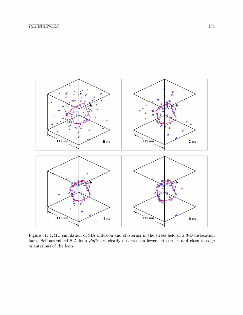
To achieve this wide range of goals, the proposed research is conveniently planned in threemajor groups of models: one at the nano-scale, a second at the mesoscale (in between nano-and macroscopic), and a third at the macro-scale. To develop full computational description ofplasticity, fracture and failure phenomena, we plan to continue our development and applicationsof Advanced Rate Theory, Kinetic Monte Carlo (KMC), and Dislocation Dynamics (DD) models ofmicrostructure evolution, irradiation-induced phase transitions, and dislocation-defect interactionmechanisms. The input parameters to this group of models (e.g. defect energetics, or partitioningin collision cascades, etc.) are very few, and will be derived from on-going Ab-initio or MD models,or directly from experimental measurements. The results of these models will also be directlycompared to experimental data, for example the heterogeneous distribution of Self-Interstitial Atom(SIA) clusters, dislocation decoration, loop raft formation, vacancy-helium cluster density and size,
3 RESEARCH OBJECTIVES 15
types and temperature dependence of irradiation-induced phases, critical stresses required to freedislocations from defect clusters, precipitates, etc.
The next level of models will be aimed at simulations of plasticity and fracture mechanisms atlength scales that are not accessible by atomistic simulations or by continuum mechanics. Method-ologies for this meso-scale will be aimed at material volumes that are in the 1-30 µm range, andwould require extensive computer simulations of the collective behavior of significant statisticalrepresentation of the microstructure. We have been advancing two new approaches in this area.The first is a significant modification of the standard KMC simulation technique. The key newdevelopment here is the ability to include, for the first time, the effects of the internal elastic fieldon the heterogenous evolution of the microstructure. This approach will be applied to the simula-tion of large-scale microstructure evolution and collective aspects of defect-dislocation interactions.Although the KMC and DD methods will be used in both the first and second group of models, thedistinction lies in the level of detail. At the nano-scale, problems of a single dislocation-defect, ormultiple defects will be pursued, while collective behavior (i.e hundreds to thousands of microstruc-ture features) will be emphasized. DD simulations will focus on radiation hardening (or softening),plastic instabilities in dislocation channels or shear bands, and detailed 3-D models of the DBTTin irradiated BCC metals and alloys.
To connect our models at the nano- and meso-scales to engineering design, we plan to pursue thedevelopment of a number of coupled discrete-continuummodels of fracture and failure processes. Wehave succeeded in the development of a coupled FEM-DD method for the simulation of the DBTTin irradiated materials. We plan to extend this work in two new directions: (1) applications topredictions of the onset of brittle fracture in irradiation testing, as well as realistic FW/B geometry;(2) modeling fatigue crack growth in BCC alloys (especially Fe and W) under irradiation conditions.A new revolutionary approach for polycrystalline plastic deformation of fusion materials is alsoproposed. This approach is based on a variational Galeriken formulation of Gibbs free energy fordislocations, grain boundaries and the grain matrix itself. A set of equations is derived for degreesof freedom representing with dislocation motion, grain boundary motion, and material motion. Themodel will tightly couple DD, GGD and the meshfree computational methods. The presence ofinhomogeneous plastic strain in the form of dislocation channels and slip bands (in fatigue) willrequire the utilization of meshfree methods, since FEM implementations are notoriously inaccuratein modeling localization phenomena and fracture processes. On the applications side, we planto continue our recent efforts in the Virtual International Test Assembly (VISTA) collaboration.This will involve three main aspects: (1) damage function development; (2) 3-D FEM modeldevelopment; (3) virtual module performance evaluation and testing. In addition, we will alsocontinue our effort on the construction of a community-shared Web-based fusion materials database.In the following, we outline our research plan, and describe how we will accomplish the variousproposed tasks.
4 RESEARCH PLAN 16
4 Research Plan
4.1 KMC & Rate Theory Modeling of Microstructure Evolution
4.1.1 Kinetic Monte Carlo Simulation of Defects
So far in all KMC simulation codes, the elastic interaction between defects, and between defectsand other microstructure (e.g. dislocations) have been ignored. For example, the simulations ofALSOME (Heinisch, 1990; Heinisch, 1995; Heinisch and Singh, 1996; Jaraiz, Gilmer, Poate and de laRubia, 1997; Heinisch and Singh, 1997) or BIGMAC (Soneda and Diaz de la Rubia, 1998; Caturla,Soneda, Alonso, Wirth, Diaz de la Rubia and Perlado, 2000) do not explicitly take the effects ofthe internal stress field into consideration. However, the elastic interaction between dislocationsand point defects that result from collision cascades play a key role in determining the effectsof irradiation on mechanical properties. Any simulation methodology must also address the manydiffusional pathways available, and reveal the dependence on temperature and dose so as to compareto experiments. In order to carry out KMC simulations for the evolution of defect distributions,several kinetic data are required: activation energy and prefactors for the motion of vacancies,self interstitial atoms (SIAs), vacancy and SIA clusters, the stand-off distance of dislocations, andthe atomic details of cluster-cluster interactions. These parameters can be obtained from MD orMolecular Statics (MS) simulations that are on-going within the US fusion materials program.
The jump frequency for a possible jump of a cluster, i, to take place is given by:
ri = ω0 exp(− EikBT
) (1)
where ω0 is the pre-exponential factor of the defect cluster, kB the Boltzmann constant, Ei the‘effective’ activation energy for jumps of the cluster, and T is the absolute temperature. The valuesof Ei for interstitials and vacancies can be obtained from MD calculations.
In many applications of the MC method, such as the equilibration of atomic positions in adefected crystal, the space of possible configurations that the system can assume is continuous.Therefore, there exists (in theory) an infinite number of new configurations available to the systemat any MC step. However, since we are simulating defects in a volume of finite size which evolvesaccording to a finite set of physical or mechanical mechanisms, the number of new configurationsavailable at any MC step is finite and enumerable. This configuration space is discrete. In otherwords, at each MC step, we can determine all of the potential changes that the system can possiblyundergo. Therefore, instead of attempting a random change to the system at each simulationstep and then accepting or rejecting that change based on some criterion (e.g., the Metropolis MCmethod(Metropolis, Rosenbluth, Rosenbluth, Teller and Teller, 1953)), we choose and execute onechange from the list of all possible changes at each simulation step. The choice is made based onthe relative rates at which each change can occur (i.e., the probability of choosing one particularreaction instead of another is proportional to the rate at which the reaction occurs relative to therates of the other reactions).
Thus, simulation of microstructure evolution of cascade-induced damage is accomplished by aKMC procedure in which one reaction is executed at one site during each time step. The firststep in KMC simulations is to tabulate the rate at which an event (i) will take place anywhere
4 RESEARCH PLAN 17
in the system, ri. The probability of selecting an event is simply equal to the rate at which theevent occurs relative to the sum of all possible event rates. Once an event is chosen, the systemis changed appropriately, and the list of events that can occur at the next KMC step is updated.Therefore, at each KMC step, one event denoted by m is randomly selected from all possible Mevents, as follows:
m−1
i=0ri
M
i=0ri
< ξ1 <
m
i=0ri
M
i=0ri
(2)
where ri is the rate at which event i occurs (r0 = 0) and ξ1 is a random number uniformlydistributed in the range [0, 1]. The way in which theM events are labeled (i.e., by specifying whichevents correspond to i = 1, 2, 3, . . . ,m, . . . ,M) is arbitrary. After an event is chosen and executed,the total number of possible events, M , and the sequence in which the events are labeled, willchange.
The reciprocal of an atomic jump probability per unit time is the residence time for a defectcluster that moves by that specific type of jump. Since the jump probabilities of all the differenttypes of jumps are independent, the overall probability per unit time for the system to change itsstate by any type of jump step is just the sum of all the possible specific jump type probabilities,and so the residence time that would have elapsed for the system in a specific configuration is thereciprocal of this overall jump probability:
∆t =1
M
i=0ri
(3)
which is independent of the chosen transition. It may also be important to include the appropriatedistribution of escape times. For random uncorrelated processes, this is a Poisson distribution. Ifξ2 is a random number from 0 to 1, the elapsed time for a particular transition is given by
∆t =− ln ξ2M
i=0ri
(4)
The system is then advanced to the final state of the chosen transition and the process isrepeated. The expression for ∆t in Eq. 4 is rigorous (Bortz, Kalos and Lebowitz, 1975), and aderivation is also provided by Battaile and Srolovitz (1997).
A cascade is introduced into the simulation box at a random position in terms of a certaindamage production rate. The point defects produced by the cascade then instantly interact witheach other, and lead to recombination and clustering. The set of atoms in the simulation system isthen be monitored for diffusional modification prior to the arrival of the next cascade, i.e. in thetime TC . When a jump is made, a time equal to the net residence time (calculated using Eqn. 4)is subtracted from TC so that there is less time remaining for further jumps in the allotted timeperiod. This process is iterated until the time of making any jump is greater than the remainingtime. Whenever a jump is to be made, the specific one is determined by random choice based on therelative probabilities of all potential jumps as described above. When the remaining time reacheszero, the clock is turned ahead by TC and another cascade is then introduced. An implementationalgorithm of this cascade damage simulation is described next.
4 RESEARCH PLAN 18
4.1.2 Elastic Interactions between Point Defects
The concept of KMC simulation provides a powerful tool in the study of atomic point defectsdistribution process of irradiation damage, which can be experimentally verified (e.g.. by TEM(Yamakawa and Shimomura, 1988)). As a result, physical mechanisms for most of individual pointdefect motions are extremely difficult to obtain under real observations. For example, the phenom-ena of loop raft formation, dislocation decoration and dislocation wall formation rely heavily uponthe properties of defects and the elastic interactions between them. Very little experimental resultson the magnitude of these interactions exists. However, so far, all KMC computer simulations formicrostructure evolution under irradiation have not considered the influence of the internal andapplied stress fields on defect motion (for example Soneda and Diaz de la Rubia (1998), Caturlaet al. (2000), Soneda and Diaz de la Rubia (2001)). We propose here to continue our developmentof KMC simulations, where the elastic interactions between SIA/vacancy clusters themselves, SIAand vacancy clusters, and SIA/vacancy clusters and dislocations are explicitly accounted for.
4.1.3 Implementation of KMC Algorithm
SIA clusters are directly produced on the periphery of collision cascades, and they may containfrom a few atoms up to tens of atoms in the near vicinity of the cascade (Bacon and Diaz de laRubia, 1994). Such clusters are extremely mobile, and migrate predominantly along highly-packedcrystallographic directions, with migration energies of less than 0.1 eV (Bacon and Diaz de la Rubia,1994; Soneda and Diaz de la Rubia, 1998). Small SIA clusters may also spontaneously change theirBurgers vector, and thus have the flexibility to translate along various crystallographic directions iftheir motion is not obstructed by internal strain fields. Since MD simulations have shown that themajority of SIA clusters have the form of mobile (glissile) perfect dislocation loops, in this work,we represent SIA clusters as small prismatic, rigid and circular dislocation loops. As for vacancies,small spherical voids are employed to approximate single vacancies and vacancy clusters.
The temperature dependence of the jump frequency of defect clusters diffusion is given byEquation(1). In our KMC simulation, the elastic interaction is incorporated. The influence ofother defects and the external stress on one SIA or vacancy cluster is given by the stress field σij .By applying the infinitesimal dislocation loop approximation for SIA clusters , the work necessaryto form the loop characterized by normal n, Burgers vector b and area δA in the stress field σij isSIA cluster interaction energy Eint, and is given by
EI =Vσ(1)ij ε
(2)ij dV (5)
in which σ(1)ij is the stress arising from the first dislocation and ε
(2)ij the strain originating in the
other. For the present study, if the second loop (defect cluster) is assumed to be infinitesimal, theinteraction energy can be simplified to (Kroupa, 1966)
EI = δA(2)n(2)i σ
(1)ij b
(2)j (6)
where n(2)i is the unit normal vector to the defect cluster habit plane of area δA(2). The total cluster
activation energy is then given by:Em = Em +∆Eint (7)
4 RESEARCH PLAN 19
where Em is the activation energy in a perfect crystal structure and can be obtained by eitherexperiments or MD simulations, and ∆Eint the difference in the interaction energy of an defectcluster placed at two neighboring equivalent position in the crystal. This includes the effects offorces and moments on the virtual loop or microvoid motion.
The implementation can be demonstrated in detail through a cascade damage flowchart, simplydescribed below. With the initiation of dislocation distribution, cascade damage rate and matrixtemperature as well as the initial calculation and summation of atomic jump rates, the key stepslie in the execution of the thermal diffusion loop and can be described as follows:
1. Select a jump path at random weighting by individual rate;
2. Make the jump;
3. Update and sum up jump rates;
4. Turn ahead simulation clock;
5. Iterate step 1 through 4 until designated damage dose (in terms of the number of cascades)is achieved.
Selection of the jump path by a linear search is represented by a cumulative and conditionalprobability process, shown in Figure (3). Suppose that there are three jumping atoms, the first hastwo jump paths and the second and third each have three. The eight available jump paths haveprobabilities p11, p12, p21, p22, p23, p31,p32 and p33 respectively.
P
P
P11 P12P22P21 P23 P31 P33P32
atom 1 atom 2 atom 3
Figure 3: A schematic illustration of the linear procedure used to select the jump path. Path p31is a randomly chosen event on a line segment of length P .
Suppose now that the jump path, p31, has been randomly selected. This is equivalent to:ξ < (p11 + p12 + p21 + p22 + p23 + p31)/P , where P is the total length of the segment and ξ is arandom number over the interval [0, 1]. For a large system, the relationship for selecting the processcan be written as
ξ <K
i=1
ni
j=1
pij/
N
i=1
ni
j=1
pij
(8)
4 RESEARCH PLAN 20
where pij is the jump rate for the i-th particle at the j-th jump path, n(i) is the total numberof jump paths for the i-th particle, N is the total number of particles. Eq. 8 indicates the K-thparticle is selected with K < N .
4.1.4 Diffusion of Glissile SIA Clusters
The fact that SIA and vacancy clusters are produced directly in the high-energy displacementcascades has significant effect on damage accumulation behavior, and thus physical and mechanicalproperties of materials under cascade damage conditions. The 1-D motion of small SIA clustersis especially important, because of their influence on dislocation decoration (Stiegler and Bloom,1971; Singh, Horsewell, Toft and Edwards, 1995b), and formation of rafts of dislocation loops(Singh,Evans, Horsewell, Toft and Edwards, 1995a). In addition, the restriction of diffusion of SIA clustersto 1-D leads to a reduction in the reaction rate with other defects because one dimensionally movingclusters are able to travel in the atmosphere of randomly distributed lattice defects through largerdistances than those 3-D moving ones, and consequently the possibility that such SIA clustersannihilate at extended sinks such as pre-existing dislocations and grain boundaries increase. Atthe same time lattice defects affect the motion of one dimensionally diffusing clusters in a moresubstantial way than they influence the motion of vacancies since one dimensionally moving clustershave less chances to avoid obstacles by changing their direction of diffusion (Dudarev, 2000). Asa consequence, a diffusion bias is established during steady-state irradiation whereby the vacancyconcentration can greatly exceed that of SIAs. In addition to the 1-D diffusion of SIA clusters,the motion of a single SIA is also of interest. In order to investigate the migration mechanism ofinterstitial clusters, Fig. 4 shows the trajectories of the centers of mass of an SIA cluster containing6 interstitials for diffusion at 300 K with different activation energies of direction change of itsBurgers vector. The transition from 1-D motion to 3-D diffusion is clearly dependent on thisactivation energy, which must be determined by MD or MS simulations.
4.1.5 Accumulation of Radiation Damage
Due to the low activation energies of SIAs and SIA clusters (< 0.1 eV), a typical diffusion eventrelated to SIAs can occur on the order of 1012 (or even more) times per second at room temperature,and would typically be important in the time evolution of the system. However, the accumulationof radiation damage occurs over hundreds to millions of seconds. A direct classical dynamicssimulation which necessarily has to faithfully track all this vibrational motion would take thousandsof years of computer calculations on the fastest present day computer before a single transition canbe expected to occur! It is clear that meaningful studies of irradiation damage evolution cannot becarried out by simply simulating the classical dynamics of defect clusters. It is essential to simulatethe system on a much longer time scale. This time scale problem is one of the important challengesin computational research on atomic scale systems, and we plan to tackle this problem as describednext.
Since it is almost impossible to study a continuous cascade damage process by tracing everyfast event of SIAs, an alternative has to be found to track the fates of all defect species andprovide a prediction of the microstructural evolution under irradiation. As a matter of fact, theMonte Carlo simulation method for particle transport has been extensively used in present dayunderstanding of radiation damage phenomena. In this method, sampling is conducted from a
4 RESEARCH PLAN 21
Figure 4: Center-of-mass trajectories of a SIA cluster containing 6 interstitials migration for 10,000consecutive KMC steps at 300K with different reorientation activation energies. The units are inlattice constants. All the straight line segments are oriented along the < 111 > directions.
probability distribution according to relevant physical laws. For a small glissile SIA cluster, thepossible event that could happened to it is either getting trapped in the strain field of anotherdefect cluster such as cavities and small dislocation loops or line defects such as dislocations, ortraveling one-dimensionally in the crystal. Statistically, the fraction of absorbed clusters dependson the strength of sinks.
There are two important aspects in the kinetics of one-dimensionally diffusional defects in com-parison to the kinetics of three-dimensionally diffusional defects: (1) the range of free migrationand (2) absorption once the defect is trapped in the strain field of another defect (including pre-existing defects) (Trinkaus, Singh, and Foreman, 1997a). The existing treatment of interactionsbetween mobile SIA clusters and lattice defects is based on the mean-field approach, where theeffective range of motion of clusters in the material is characterized by the mean free path λ. Fora defect of configuration i migrating one-dimensionally in a crystal containing a number density cjof defects of configuration j with effective interaction cross section σij = πr2ij and a line density
ρ of dislocations with effective interaction diameter di the reciprocal mean free path Πi = λ−1i isgiven by (Trinkaus, Singh and Woo, 1994)
Πi = λ−1i =j
σijcj + diρ (9)
4 RESEARCH PLAN 22
where ρ = πρ4 is the dislocation line length per unit volume projected on a plane perpendicular to
the migration direction. σij and di are determined by the mutual elastic defect interaction.
The probability of a defect getting absorbed at a sink after moving a distance ∆l in the compu-tation box is then given by
P = 1− exp −∆lλi
(10)
Because the MC method is used to determine the eventual fate of a cluster in terms of proba-bilities of a certain number of events, this scheme is so-called “Event Monte Carlo” (EMC).
In a long-time-scale simulation, since the trajectories of defects cannot be faithfully followedin all its details, a scheme coupling KMC and EMC is a reasonable compromise. KMC can beused to capture strong space-time correlations in the system, and EMC can provide the means toextrapolate from small damage dose levels to larger values. This hybrid scheme is similar to thepredictor-corrector integration method, and is described as follows:
1. Select a simulation box, say 0.5 µm on the box edge, and distributed some dislocation loopsin terms of a designed dislocation density;
2. Choose a starting point at some low dose damage level, say 10−6 dpa. The total numberof cascades and corresponding SIA clusters can be readily obtained by using the empiricalrelationship between the number of Frenkel pairs and the kinetic energy of the PKA (Bacon,Gao and Osetsky, 2000). The corresponding size distribution of clusters can also be acquiredfrom MD simulation results;
3. Perform KMC simulation for a short time, which can be taken as the time required for oneSIA cluster to cross the simulation box several times;
4. Terminate the KMC simulation;
5. Perform quasi-equilibrium EMC calculation for each and every mobile SIA clusters to approx-imate the long-term redistribution of defects;
6. Use EMC to accumulate defect damage, with the corresponding size distribution, and use thedata as a new starting point at a higher dose (e.g. 10−5 dpa);
7. Repeat steps (3) to (6) to the desired dose level.
4.1.6 The Role of Advanced Rate Theory
Advanced Rate Theory refers to considerations of a number of processes and phenomena that havebeen shown by either MD or KMC, and were not considered in the original development of theStandard Rate Theory. These are: (1) simultaneous nucleation and growth of vacancy-heliumclusters without artificial separation of regimes, (2) the asymmetric split of defects into sessile andglissile portions, following the cascade event; the so-called production bias, (3) the transition indefect diffusional kinetics from 1-D to 3-D, and the ensuing effects on microstructure evolution; (4)cascade-induced dynamic events, such as precipitate re-solution and secondary bubble nucleation.We plan to continue the development of our Advanced Rate theory code (Sharafat and Ghoniem,
4 RESEARCH PLAN 23
2000) that has been calibrated with recent experiments to include these four aspects of the theory.Moreover, we will use the code to check on the global features of damage evolution by the KMCmethod, as described before. The main value of KMC/EMC simulations will be the ability todetermine the conditions of spatial segregation of defects. The influence of such segregation on themechanical properties can be studied by DD simulations, as will be explained in Subsection ??.The specific topics that will be addressed in this area are:
1. Self-consistent formulation of the distribution of clustered and freely migrating point defects,in the presence of simultaneous helium clustering with vacancies under conditions of highhelium production rates;
2. Incorporation of helium transport mechanisms by pipe diffusion in dislocation cores, by dis-location drag under stress, and by bubble mobility.
3. Coupled moment equations and re-construction of the size distribution of helium-vacancyclusters.
4. Simultaneous evolution of non-equilibrium phases, and coupling between helium cluster andphase evolution (see below on phase evolution).
5. Coupled rate equations for helium-vacancy cluster evolution on grain boundaries for couplingwith the creep rupture modeling efforts.
6. Applications of the models to experimental analysis and alloy design.
4.1.7 Radiation-Induced Phase Transitions
Phase transitions under irradiation are generally non-equilibrium, as they are influenced by a num-ber of mechanisms: enhanced diffusion, solute segregation, and radiation-induced dissolution of newphases by disordering and ballistic displacements. We plan to develop kinetic models for the non-equilibrium precipitate phases in both ferritic steels and vanadium. In particular, we will focus onoxide-dispersoids in ODS steels (e.g. Y2O3), and on Ti-oxy-carbo-nitrides in vanadium. The meth-ods developed here will be readily transferable to other irradiation-induced phase transformations.Ultra-fine non-equilibrium phases, which are homogeneously distributed as nano-scale coherent so-lute clusters, will be modeled, building on our most recent work on cluster dynamics and kineticmodeling of non-equilibrium phase evolution (Demetriou, Ghoniem and Lavine, 2002c; Demetriou,Ghoniem and Lavine, 2002b; Demetriou et al., 2002c; Demetriou et al., 2002b).
Demetriou, Ghoniem and Lavine (2002a) developed a CALPHAD algorithm to compute themetastable W-C phase diagram in the vicinity of the metastable reactions involving the car-bides by reproducing the equilibrium boundaries using optimized free energy data obtained from(Gustafson, 1986), and by extending the stable boundaries into regions of metastability as sug-gested by (Perepezko and Boettinger, 1983). The computed stable phase equilibria are in excellentagreement with those computed by (Gustafson, 1986), which closely resemble experimental phaseequilibrium data presented by (Rudy, 1969). Modeling non-equilibrium phases under irradiationwill be based on our recent efforts in this area, and will be closely tied to our microstructure evolu-tion models described earlier, and will include the interaction of interstitial solutes (i.e., C, N, O)with extended defects.
4 RESEARCH PLAN 24
4.2 Modeling Plasticity of Irradiated Materials
4.2.1 Radiation Hardening & Plastic Instabilities
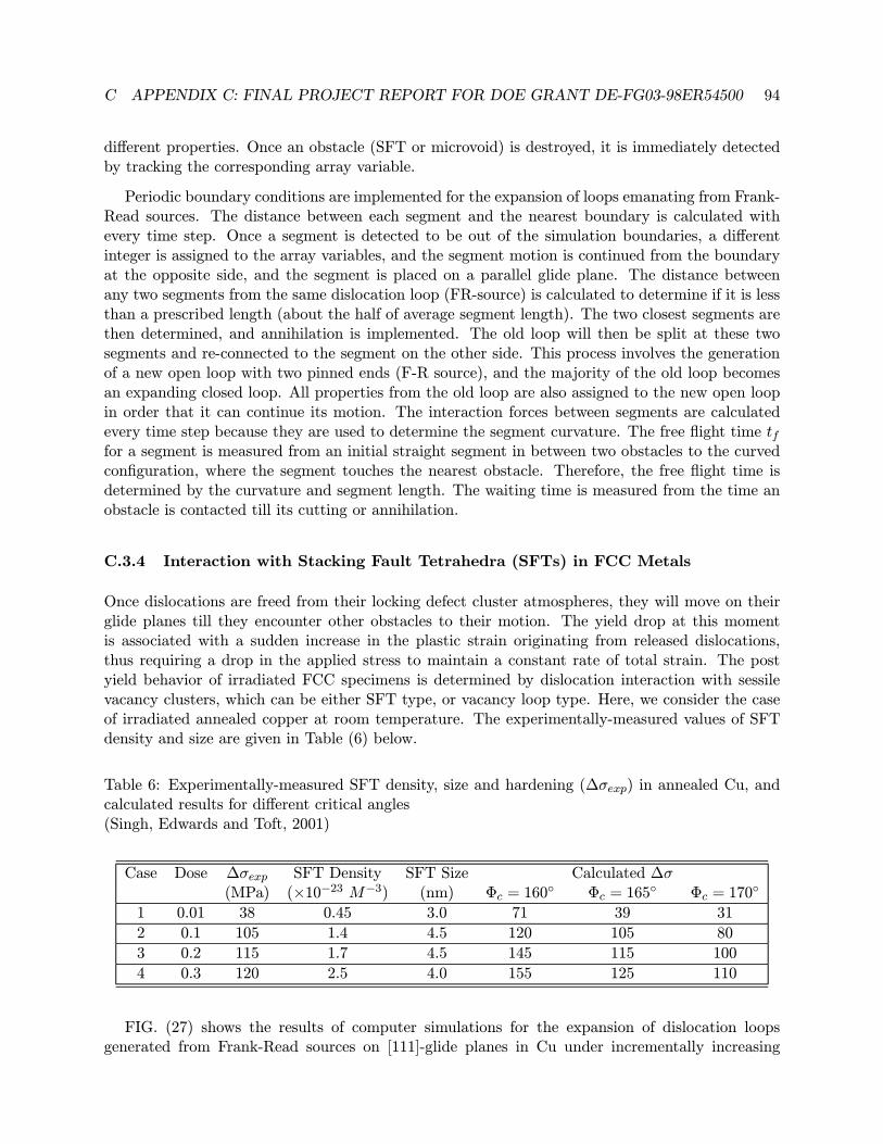
Many experimental observations have shown that neutron irradiation of metals and alloys at tem-peratures below recovery stage V causes a substantial increase in the upper yield stress (radiationhardening), and beyond a certain dose level, induces a yield drop and plastic instability. Fur-thermore, the post-deformation microstructure of a specimen showing the upper yield point hasdemonstrated two significant features. First, the onset of plastic deformation is generally found tocoincide with the formation of “cleared”channels, where practically all plastic deformation takesplace. The second feature refers to the fact that the material volume in between cleared channelsremains almost undeformed (i.e. no new dislocations are generated during deformation). In otherwords, the initiation of plastic deformation in these irradiated materials occurs in a very localizedfashion. This specific type of plastic flow localization is considered to be one of many possibilitiesof plastic instabilities in both irradiated and unirradiated materials.
Figure 5: Results of computer simulations for dislocation microstructure deformation in copperdeformed to increasing levels of strain (shown next to each microstructure
( After Wang, Ghoniem, LeSar and Sriram (2003))
In this part of the investigation, we plan to continue the development of our parametric DDto assess the physical mechanisms, which are responsible for the initiation of plastic instability inirradiated FCC and BCC metals. The computational capabilities of our method are very substantialnow, and realistic simulations of small material volumes (e.g. several microns in size) can beroutinely carried out, as can be seen in Figure (5). We plan to investigate the mechanisms ofdislocation unlocking from defect clusters in the form of Stacking Fault Tetrahedra, SIA clusters,
4 RESEARCH PLAN 25
microvoids, and ultra-fine radiation-induced precipitates. We will also investigate the mechanismsof structural softening in flow channels as a consequence of dislocation interaction with these defectfeatures.
One of the main problems that have faced the simulation community is the enormous densityof defect clusters contained in micron-size simulation boxes. A direct numerical simulation of theinteraction between dislocations and radiation-induced defects is very limited. We plan to developa new statistically-based DD simulation method, where the details of the interaction betweendislocations and small-size defects are represented by statistical power spectra, modeled as timeseries. Invoking the concept of ergodicity, we can perform a limited number of detailed simulationsbetween single dislocations and statistical distributions of defects, from which we can determinethe details of dislocation-defect interaction forces. These statistical fluctuating components of thePeach-Kohler force will be added to the deterministic counterpart computed from the local stressand self-force. Therefore, we plan to modify the main equations of motion of the Parametric DD,so as to include stochastic fluctuations from defect fields and thus represent thermally-activatedprocesses aS well. The procedure will be similar to Langevin Dynamics in particle simulationtechniques, as opposed to classical MD simulations.
4.2.2 A Self-consistent Meso-mechanics Variational Formulation
It is immediately noted that the variational principle for power dissipation in dislocation dynamicsis quite similar to the variational form used for grain growth dynamics. Our plan is then to developa self-consistent and more general variational form that accounts for power dissipation by motionof both the grain boundaries and the interior dislocations. We will follow the thermodynamicsformulation of Ghoniem, Singh, Sun and Diaz de la Rubia (2000a), where the components of theGibbs free energy will include relevant contributions from the dislocation microstructure as well asthe grain boundaries. We also plan to generalize the grain boundary meso-dynamics to 3-D, whereGBs are modeled as parameterized surfaces rather than parameterized space curves. Consider thevirtual motion of all elements of the dislocation and GB microstructure in 3-D space. FollowingGhoniem et al. (2000a), we have the following forms of the Gibbs free energy rate:
δG = −I=Nloop
I=1 Γd
(fS + fO + fPK) · δvd | ds | (11)
−J=NGB
J=1 ΓGB
γ(∂vsgb∂s
+vngbR) +
1
2((σ+ : + +E+self )− (σ− : − +E−self ))δvngb dΓGB
−Ω
1
2δ(σ : ˙)dΩ+
ΓGB
δv · hdΓGB +Ω
δv · bdΩ
where the first three terms (first line in the equation) are for the rate of Gibbs free energy due tothe dislocation microstructure, Nloop is the total number of dislocation loops in the system, Γ isa specific parameterized line contour representing each dislocation loop, fS is the force associatedwith self-energy of a dislocation loop, fO is an osmotic force on a dislocation due to point defectabsorption, fPK = σ · b × t is the Peach-Kohler force (where the stress tensor includes applied
4 RESEARCH PLAN 26
and internal stress sources from other dislocations and GBs, b is Burgers vector and t the tangentvector), and vd is the dislocation velocity vector. Terms in the second line is from contributions fromGB motion, and the third line is for contributions by the applied forces at the material boundaryand the body forces. Note that this variational equation contains line integrals for dislocations,surface integrals for GBs and volume integrals for body forces and internal stresses. Also, the freeenergy terms for dislocations are coupled with both matrix and GB energy terms, because theself energy of dislocations must be computed from both sides of a grain boundary (+ and - ) todetermine an effective driving force for GB motion. In addition, GBs will act as sources and sinksfor dislocation loops, and thus influence their populations. In the previous equation, three differentvelocities for three different types of Degrees of Freedom (DOF) will have to be simultaneouslydetermined. These are velocities assigned to DOF on dislocation lines, denoted by vd, velocitiesassigned to DOF on GBs, denoted by vgb, and velocities of material points that can be determinedby the mesh-free method, and those are denoted by v.
The second law of thermodynamics dictates that Gibbs free energy given by EQN. 11 must con-tinuously decrease for the irreversible process of microstructure evolution as a consequence of theincrease in the total system entropy. The dissipation of this free energy is described phenomeno-logically by considering all microscopic dissipative processes during dislocation and GB motion,as:
δGt = −I=Nloop
I=1 Γ
BαkVαδrk | ds | −I=NGB
J=1 ΓGB
1
2µv2gbds (12)
The first integral is for the dissipation of free energy by dislocation motion, where the resistivitymatrix can have three independent components (two for glide and one for climb), depending on thecrystal structure and temperature. It is expressed as:
[Bαk] =
B1 0 00 B2 00 0 B3
(13)
The second integral is for the dissipation by motion of grain boundaries, where µ is the grainboundary mobility. Equating EQN. 11 to EQN. 12, and performing parameterized discretiztion,we obtain a set of equations for the DOF for the entire system. This set is composed of threecoupled sets of equations, one describing the motion of nodes on dislocation lines, the second setdescribes the motion of nodes on GB surfaces, and the third set for material point motion thatrequire solution by mesh-free methods. We thus have formulated a self-consistent method that candescribe the simultaneous evolution of dislocation loops, GBs and material points.
One key idea is that the microstructure can be re-created from the statistics of the spatialdistribution of the nodes. One can think of these nodes as particles suspended in 3-D spacewith statistical distribution properties (e.g. density, spatial correlation functions, etc.). Thus,solution of the dynamical equations for a relatively small volume of dislocation loops can be usedto statistically re-generate equivalent dislocation loop microstructure in various grains (of coursewith some limitation on stress variations from grain to the next). Similarly, the GB microstructurecan be statistically regenerated from the information obtained in small volumes.
4 RESEARCH PLAN 27
4.3 Modeling Fracture Processes
Understanding the DBTT in fusion structural materials requires two main steps. First, we plan tomodel simple crystals that do not contain other initiation sites for micro-cracks ahead of a maincrack. In this case, the controlling factors of the DBTT are at the nano-scale, and are determinedby the nucleation conditions or or by various effects on dislocation mobility ahead of cracks. Sofar, there has been no development in the lkiterature for modeling full 3-D conditions of cracksof arbitrary shapes with emitted dislocations. All research reported so far is for simpolistic 2-D analysis. Second, in alloys containing micro-crack initiation sites (e.g. ferritic/ martensiticsteels), the behavior is dominated by the distribution of such initiating sites (carbides or triple-point junctions). In this second area, we plan to extend the Master Curve approach of Odette andco-workers (Odette and He, 2002) by developing a computational analog that combines 2-D DDwith 2-D FEM simulations of crack-tip plasticity. This will be explained in the next section.
In the first area of modeling fracture processes, future research will focus on the following aspectsrelated to the DBT behavior:
• Effects of dislocation pinning ahead of crack tip as a result of their interaction with radiationinduced defects, precipitates or solute atoms;
• Effects of stress triaxiality;• Effects of prior dislocation microstructure (pre-deformed);• Large scale simulation of Crack-Dislocation ensemble in the transition region.
In the following sections, we will briefly describe our proposed research plan.
4.3.1 Effects of Nano-scale Impurities and Defect Clusters
It has been shown that impurities have strong effect on the DBTT for Cr-based alloys. Understand-ing of the effects of impurities and solutes on the DBTT is critical to the development of alloysthat are resistant to embrittlement. In our previous work (Huang and Ghoniem, 2002), the densityof sessile interstitial atom (SIA) clusters was found to greatly affect the Critical Resolved ShearStress(CRSS) for dislocation motion. The question arise then, what’s the effect of these clustersif they are located near the crack tip. The CRSS of each dislocation loop will be changed, it isexpected that they will influence the back stress on the crack, and hence will influence on materialductility? Our objective is to understand the effect of these SIA clusters, microvoids, precipitateinclusions, and interstitial impurities on the DBTT. This will hopefully enable us to design moreembrittlement-resistant alloys.
4.3.2 Pre-deformed microstructure
Sharp DBTT transitions can only occur in well prepared dislocation-free crystals. Thus, a pre-existing dislocation microstructure will change the DBT. FIG. 6 shows an illustration of differentdensities of randomly distributed dislocations that will be placed ahead of 3-D crack tips. We plan
4 RESEARCH PLAN 28
to determine the mechanisms by which the pre-existing dislocation microstructure influence emitteddislocation motion, and hence the transition behavior from brittle to ductile. One possibility isthat with a high density of dislocation, dipoles and junctions are easily formed, so higher stressare needed to break these strong interactions, causing immobility of these dislocations, and hencehigher stress field near crack tip. The effect of different densities of initially distributed dislocationswill be studied in our future work.
0
2
4
[010] (m)
0
2
4
[00
1](
m)
0
2
4[100] (m)
0
2
4[00
1](
m)
0
2
4[100] (m)
0
2
4
[010] (m)
X Y
Z
0
2
4 [01
0](
m)
0 2 4
[001] (m)
0
2
4
[100] (m)0 2 4
[001] (m)
0
2
4[100] (m)
0
2
4[01
0](
m)
X
Y
Z
( a ) ( b )
Figure 6: Illustration of different dislocation densities within one single cube. (a) low density (b)high density
4.3.3 Effects of stress triaxiality
Three-dimensional surface and embedded cracks are usually encountered in engineering structuresat varies temperatures, thus it is necessary to understand the ductility of the material at variestemperatures. A large effort has been invested on the solution of the stress field of 3-D cracks.Sih and coworkers (Hartranft and Sih, 1969; Hartranft and Sih, 1977; Kassir and Sih, 1966; Sihand Chen, 1981) performed a thorough study of three-dimensional crack problems. The analyticalforms of the stress field near crack crack surface is obtained (Kassir and Sih, 1966) if the stressintensity factor K is known. But the problem is how can we obtain these Ks when cracks areinteracting with dislocations? Here our future objective is to avoid these crack stress calculationsin 3-D. We plan to develop an extension of the earlier representation of cracks with dislocationdistributions to the more challenging case of fully 3-D cracks of arbitrary shape. We believe thatthis will represent an important step in the realistic modeling of crack tip plasticity of practicalmaterials.
IIt is known that the image force due to crack free surface can be obtained in analytical forms((Lin, Lin, Chen and Chang, 1997; lin Pan, 1995; Wang and Lee, 1998)) in the 2-D case. However,for 3-D problems, the shielding effect of dislocations is still unknown. The Finite element methodhas been used to solve some simple cases (Jr., 2000), but for the shielding effect on cracks, theFEM will be very time-consuming and impractical. Here, we will introduce the notion of 3-D crackdislocation loop distribution to avoid the painstaking iterative calculations in FEM approaches.
As discussed in literature (Lardner, 1974), a crack can be represented by a series of so called
4 RESEARCH PLAN 29
Figure 7: A Plain crack in infinite domain is represented by an array of edge dislocations
crack dislocation as shown in FIG. 7. The stress field of these distributed edge dislocations isthe same as that generated by a crack. Thus the crack problem can be transformed to solve thedistribution of the dislocations, and as if there is no crack in the material. For a simple 2-D case,the crack can be represented by n edge dislocations, by solving equation set:
l=k
− µb
2π(1− ν)1
xl − xk + σ = 0, k = 1, 2, ...n (14)
However, it is difficult to get the analytical solution for EQN. 14. First suggested by Leibfried(Lardner,1974), and later modified by other researchers, a continuum distribution of dislocation with densityf(x) is introduced. For the case of uniformed tensile loading, f(x) is found to be (Lardner, 1974):
f(x) = −2(1− ν)σµb
x√a2 − x2 (15)
The stress of each point near the crack tip can be obtained by the integral of the stress generatedby these continuum dislocations. So far, most of the solutions for 2-D crack problem can be easilyobtained by way of crack dislocations (Lardner, 1974). Here, our objective is to extend this conceptto solve general 3-D crack problem.
For the 3-D crack problem, these crack dislocations are expected not to be straight and infinitelylong. This is due to the fact that the stress field along the crack front is no longer uniform, anddislocations tend to be curved as shown in FIG. 8. Instead of solving a similar equation setEQN. 14, we plan to use our dislocation dynamics method to dynamically simulate the equilibriumconfiguration of discrete dislocations. Here, we assume that crack dislocation are emitted from oneside and move toward the crack front as shown in the figure under the external driving force. Dueto the interactions of these dislocations, they will pileup near the crack front and finally reach anequilibrium state. This procedure is an extension to the earlier work of Amodeo and Ghoniem on2-D pile-up dynamics.
As discussed earlier, direct calculation of image stresses due to the crack free surface is a painfulprocess. We will treat here the stress field of those real crystal dislocations as those of an externalload. Thus the combined effects of external load, emitted crystal dislocations and the mutualinteractions of crack dislocations makes an equilibrium state for each of the crack dislocations. The
4 RESEARCH PLAN 30
Glide Plane
Crystal Dislocation
Crack Dislocation
Figure 8: Opening crack with curved 3-D dislocation representation
final stress field near the crack tip will be the sum of the stresses from all the crack dislocations andall the crystal dislocations plus the external loads. Calculation of image forces and stress due tothe external load can be unified to solve a dislocation pileup problem. No image stress calculationis needed. dislocation.
As an application of crack dislocations, we plan to use closed loop crack dislocations to sim-ulate penny shaped cracks as illustrated in FIG.9. Compared with the open crack, all boundaryconditions can be fully satisfied. Our preliminary calculations of the Crack Opening Displacement(COD) and the stress fields around crack tips are extremely encouraging, and will be publishedshortly. An example of a re-constructued 3-D crack at the hexagonal grain boundary surface inbetween two grains is shown in Figure (10), which shows a hexagonal grain boundary crack subjectinternal helium pressure p. The outermost dislocation loop are chosen as the periphery of the grainboundary. A total of 15 dislocations are fitted within the crack surface, excluding the outermostbounding one. As shown in the figure, due to the interaction with the boundary, the shape of theloop are more like hexagon, this is more obvious in the outer dislocation loops. The stress contourdue to this distribution is also obtained in FIG. ??b, due to symmetry of the problem, only theshaped parts is given. It is shown that due to the effect of 3-D, when the distance to the tip is verysmall, the stress decays as 1/
√r, but is much faster at longer distances.
4.3.4 Large-scale simulation of Crack Tip Plasticity
After solving the pileup process, the whole problem can be unified to large scale simulation ofdislocation interactions, no crack will enter the calculation. All dislocations can be classified intotwo groups, one is the crack dislocations which is related to the crack tip stress and image stressfields, the other is the crystal dislocations, emitted from the crack tip, whose effect will influenceboth the distribution of crack dislocations and the total stress field around the crack tip. Withknown crack tip stress, and applying the Griffith’s theory, a final simulation of the DBTT will bedone. So our problem now can be simplified as the problem of dislocation interactions, and no crackis needed! We plan to investigate the computational issue associated with 3-D parallel dislocationdynamics code on the 160-node ISIS computational cluster at UCLA
4 RESEARCH PLAN 31
Crack Dislocation
Penny-shaped Crack
Figure 9: Representation of the openning of a penny-shaped crack
( c )
x
y
( a )
x (a)
y(a
)
0.6 0.8 1 1.2 1.40
0.2
0.4
0.6
0.8
1
1.2 zz
(p)
15
5
3
2
1.5
1.4
1.3
1.2
1.1
1.05
1
( b )
Figure 10: Shape of a 3-D grain boundary crack computed by our PDD method
4 RESEARCH PLAN 32
4.3.5 High-Temperature Helium Embrittlement
The data base on helium embrittlement and corresponding models were developed almost entirelyfor austenitic alloys. It is generally believed that F-M alloys are less sensitive to helium embrittle-ment than austenitic alloys. However, creep strength is likely to be more limiting than creep rupturefor conventional F-M alloys. The combined effects of helium and the high matrix strength of ODSsystems are not known. While in principle, vanadium alloys have high thermal creep strength,simple solid solution variants are almost certainly very vulnerable to low rupture time and ductilitydue to high helium concentrations in grain boundary bubbles. This research will address all ofthese issues, but will primarily focus on the effects of high helium concentrations. At service stresslevels, creep rupture generally occurs by the nucleation, growth and coalescence of grain boundarycavities . The nucleation stage is often rate controlling and for a variety of reasons, usually involvesheterogeneous cavity formation at grain boundary precipitates. However, this may be effectivelyshort-circuited by the conversion of stressed helium bubbles to rapidly growing cavities. Helium notonly reduces creep cavity incubation times, but also increases cavity number densities on bound-aries and the fraction of cavitated boundaries; all three of these responses to higher helium levelshave very deleterious effects on creep rupture. Even without helium, creep rupture times wouldbe very low if cavity growth took place by unconstrained boundary diffusion. However, in usefulalloys growth rates are decreased by many orders-of-magnitude by both grain boundary phasesthat lower effective boundary diffusion rates and creep accommodation of local dilations aroundheterogeneous distributions of cavitated boundary facets due to grain boundary cavity growth.
In this Task we propose do develop creep rupture models that self-consistently account for: a)nucleation, including bubble-to-cavity conversions; b) cavity growth by restricted local boundarydiffusion; and c) creep accommodation of material surrounding local dilations of cavitating bound-ary facets by stress redistribution. This will closely link to the previous task on the transportand fate of helium. Furthermore, the critical role of matrix creep strength will be integrated inthis model. Generally, high creep strength increases rupture times, although the effects of in-terconnected soft boundary zones must also be considered. In the ODS systems, the nature ofdislocation-obstacle interaction is key to providing high levels of creep strength, and will be mod-eled in detail for various dispersiods. The thermal and irradiation creep models of Ghoniem andco-workers will be integrated in this comprehensive effort. In these models, rate equations are devel-oped for various dislocation populations (e.g. mobile, slow moving and boundary dislocations), andare coupled to nucleation/growth equations for dislocation sub-boundaries, dislocation cells, andirradiation-produced point defects. Extensions of this formulation to model the behavior of ODSsystems will be particularly emphasized. While semi-analytical treatments of creep-accommodatedcavity growth are available, FEM simulation methods will be used to better quantify this pro-cess. The effect of irradiation creep on accommodation will also be treated. Various parallel andsequential multi-mechanism creep and creep rupture processes will be represented as Ashby-typemaps (creep, creep rupture and creep ductility), both for close interfacing with experiment and asa convenient design tool.
Coupled with microstructural simulations, which will help guide management of helium flowsto the grain boundaries, our creep rupture models will provide an important material design tool.We plan to assess factors, which can be effectively used to optimize competing effects. These are:grain boundary design (e.g. phases which enhance nucleation and retard growth of cavities), highmatrix creep strength (longer creep rupture time, lower ductility), fine matrix dispersions, grain size
4 RESEARCH PLAN 33
effects, dislocation cell size effects, and the effects of alloying on creep rates and helium transport.
4.4 Modeling the Ductile-to-Brittle Transition
4.4.1 Recent Physical Models of DBTT
There is a range of structural materials, mostly mutiphase materials (e.g. steels) in which microc-racks ahead of the macrocrack control the fracture toughness of the materials, see eg. (Rosenfield,Shetty and Skidmore, 1983; Veistinen and Lindroos, 1983) and references therein. It is now well-established fact that the microcracks in brittle precipitates (originated by slip in the matrix);situated ahead of notch or pre-crack is detrimental in the fracture behavior of ferritic steels. Con-ventionally, this is modelled by a critical tensile stress criterion at some distance ahead of themacrocrack tip. Since the original attempt by Ritchie, Knott and Rice (RKR) (Ritchie, Knottand Rice, 1973) to quantify the characteristic distance in relation to grain size, there has beenan upsurge in the literature (for a recent review see (Knott, 2000)). Now a commonly assumedrelation that ferrite grains are grown out of austenite by the rejection of carbon. Thus if there aremore ferrite grains (finer grain size) the carbides will be thinner when adjacent grains impinge oneach other. The RKR model or its variants were successful in explaining the lower-shelf fracturebehavior, but fails at the transition region. Wallin etal extended the modelling with some successto the transition region by considering variation of effective surface energy (γs + γp)(where γs thetrue surface energy and γp the plastic work done during propagation) with temperature(?). Thiseventually lead to the Master Curve (MC) Hypothesis which predicts that brittle-ductile transitionof all ferritic steels follows a universal curve. The data from different irradiation conditions ormicrostructure can be ’mapped’ into a single curve by shifting it with a ’reference temperature’T0 (Wallin, 1993; McCabe, Merkle and Wallin, 2000). Irrespective of the fact that Master curvehypothesis is an empirical relation, it is now widely used to check the reliability of structures underirradiation in the nuclear industry(ASTM, 2002). The ultimate goal of the project is to derive thephysical parameters involved in the Ductile-Brittle transition from fundamental (dislocation leveland atomistic) processes.
Hirsch-Roberts Model for Brittle-Ductile Transition
The dislocation dynamics model developed by Hirsch and Roberts (HR)(Hirsch, Roberts andSamuels, 1989; Hirsch and Roberts, 1991) was quite successful in predicting the fracture toughnessof many single crystalline materials. In this model plastic zone around the crack-tip is modelled asa dynamic array of dislocations. As the load is increased, dislocations are emitted from a sourcenear the crack-tip. The emitted dislocation impedes further emission due to its back stress at thesource position, the back stress decreases as the dislocation moves away. The plastic zone thusgenerated shields the crack-tip from external load and enhances the fracture toughness. When thecrack-tip stress intensity reaches a critical value (usually the Griffith value), fracture is assumedto occur. Since with increasing temperature dislocation velocity increases, more dislocations areemitted and the fracture toughness increases. Experimentally obtained dislocation velocities aremostly used.
Lately the model used friction stress controlled dislocation velocity law, which is appropriate forBCC metals and alloys. Using a friction stress τf = σy/
√3, where σy is the uniaxial yield stress
(here τf is equivalent to the shear yield stress when von Mises yield criterion is assumed) the pre-
4 RESEARCH PLAN 34
K
Figure 11: A schematic of the microstructural details of the crack-system we are modelling
dicted plastic zone size and crack opening displacements compares well with analytical results. Andthe stress field ahead of the crack matches with that obtained analytically by HRR (Hutchinson,1968; Rice and Rosengren, 1968) for small scale yielding in power-law hardening materials. Usingthe critical stress ahead of crack criterion this model was successfully extended to predict the lowershelf fracture toughness behavior of Ferritic steels (Hirsch and Roberts, 1997).
Recent Modeling of Cleavage Initiation in Ferritic Steels
To account the microstructural details in the fracture prediction of ferritic steels, recently wemodelled the low temperature (lower shelf) fracture behavior of Ferritic Steels (Roberts, Noronha,Wilkinson and Hirsch, 2002; Noronha, Roberts, Wilkinson and Hirsch, 2003) as follows. Thecleavage fracture in cracked-carbide particle was represented as a slit crack capable of emitting dis-locations when loaded. The basic relation of stresses used were derived by Wang and Lee(Wang andLee, 1990). To simulate the behavior of crack in a plastic zone, beyond yield (i.e σapplied > σyield,modified relations were used. They are obtained by subtracting the far-field of applied stress andadding in the far-field at yield, or in other words keeping the non-K-field constant at σyield. Thisrepresents a triaxial stress state ahead of crack of a perfectly plastic materials. With the approx-imation that crack plane is perpendicular to the loading direction and dislocations are emittedfrom the crack-tip along inclined and perfectly aligned slip planes it predicts the fracture stressinvariance found experimentally in ferritic steels. Also it enables to make a theoretical predictionof the plastic work done during crack-propagation (γp). But steels are hardening materials, andthis assumed triaxiality is far less than an approximation. Now we used the triaxial condition ap-propriate for a hardening material, with exponents n = 0.1− 0.3, the typical hardening exponentsfor ferritic steels.
Figure 13: A contour of tensile stress σ22 around the crack-tip.
4.4.2 Recent work at UCLA
Model and method of calculation
The system we model involves, a primary (macro) crack (which is the precrack in experimentalsamples) or surface cracks in practical structures. And a secondary crack which are usually crackedbrittle particles situated in the plastic zone of the primary crack (See Figure (13).
We model the macrocrack as finite element elastic-plastic crack in power-law hardening ma-terial and the secondary crack originated from brittle particle as a slit-crack capable of emittingdiscrete dislocations. The microcracks are in the field of finite element (FE)-crack, the coupling isunidirectional, meaning the presence of free-surface due the microcracks are not accounted for theFE-simulation (it is negligible due the small size of these cracks when compared to the primarycrack).
Two dimensional finite element simulations were performed using the general purpose FE code
4 RESEARCH PLAN 36
ABAQUS(Abaqus V6.2, 2001). A typical mesh used for the calculation is shown in figure 2. Theinitial radius of the crack-tip is taken to be 10−5 times the width of the specimen. Accordingly,the dimensions of the refined mesh near the crack-tip was about 10−5 of the coarsest mesh. In thesimulation of a half specimen 1544 nodes and 1407 4-node linear elements were used. Elastic-plasticconstitutive equations σ = σ0 +K
n with K=400 MPa, σ0 is the yield stress and n the hardeningexponent were used. Figure 3 shows the stress contour of tensile stress σ22 around the crack tipalong the loading direction.
The secondary crack (micro crack) is represented as a finite through-thickness crack, capable ofemitting dislocations. Its plastic zone is represented by edge dislocations on slip planes oriented atan angle to the crack plane, emanating from sources near the crack tips. These dislocations shieldthe crack (i.e. reduce the crack tip stress intensity) through the compressive stresses exerted bythem on the crack. For each positive dislocation emitted, a negative one moves into the crack. Inthe simulations, applied stress is increased according to the stress series obtained at the ’particle’ byFE-simulation. At each time step the dislocation array is equilibrated and a dislocation nucleationcriterion, is evaluated to decide whether a dislocation will be emitted. The nucleation of dislocationsreduces the local stress intensity at the crack tip such that further dislocation nucleation is impeded.In the time step immediately before a new dislocation is nucleated, the local stress intensity is atits maximum. This maximum increases steadily in magnitude as the applied stress is increasedaccording to the stress series obtained by FEM simulations. Finally, in the microcracks that failthe local stress intensity k at the crack tip exceeds the critical value for fracture (here taken as1MPa
√m). The applied stress (tensile) at this stage defines the stress at fracture (σF ) at the
microcrack. In these simulations, the dislocations move against a friction stress (which is taken asτf = σy/
√3). The obtained fracture toughness values can be mapped to temperature using the
experimentally determined variation of yield stress (σy) with temperature. Knowing the tensilestress at the microcrack at fracture σF we find the J-integral value at that applied load. This isthe Jc from which we obtain KJc =
√EJIc/(1− ν2).
4.4.3 Results
Figure (14) shows a Brittle to ductile transition (BDT) curve we obtained by using the method.The fracture toughness values calculated as a function of friction stress (or yield stress) is mappedusing the σy versus temperature data for high nitrogen mild steel reported in (Ritchie et al., 1973).Carbides in the range of 0.1−10µm with normal size distribution is used in the calculation. For yieldstresses (corresponding to each temperature) Finite Element analysis is done with the appropriateconstitutive laws and the stress at a point (1.2µm) is recorded as the load is increased. Thisstress series is then applied to each microcrack and the corresponding microscopic cleavage fracturestress is found (If the microcrack does not fail they are considered as impotent cracks and will notcontribute to the fracture toughness of the specimen). As we can see by varying one parameter itselfa scatter in the fracture toughness values is reproduced. More more work is in progress looking theeffect of position and orientation of the crack.
4.4.4 Future directions/Project Plan
Work in progress
4 RESEARCH PLAN 37
0
20
40
60
80
100
120
140
-200 -150 -100 -50 0 50 100
Temp (0C)
Fra
ctu
re t
ou
gh
ne
ss
, K
Jc(M
Pa
m1/2
)
Figure 14: The fracture toughness versus temperature curve obtained from our computation for ahigh-nitrogen mild steel
• Effect of Mixed Mode LoadingAlmost always secondary cracks are modeled as if they are parallel to and situated at thecrack-plane ahead of the macrocrack. But there were experimental observations that thesesecondary cracks could be located at some angle to the primary crack plane (?). We intendto study the effect of mixed mode loading by obtaining different stress component series byFE simulation at random off-crack plane positions, especially along different relevant angleslike 450, 70.50 etc. These stress series will then be used in the discrete dislocation simulationof crack-tip as described above. This will enable us in exploring the combined effect of sizeand position of carbides.
• Crack GrowthIrrespective of the fact that stable crack-growth has been observed around the ductile-brittletransition temperature, most modelling so far has been done considering only the unstablecleavage. This could be one of the reasons why most models predict the fracture behaviorwell at the lower shelf, whereas it fails to predict the transition. Here we intend to extendthe model to include the crack-growth. In the DD simulation this demands having dynamicmultiple slip planes along which dislocations can be emitted as the crack propagates. Wehave already implemented the multiple slip plane, see (?). Now we intend to simulate thecrack growth using the following relation between crack velocity and crack-tip stress intensityfactor (?).
vc = bMc(K
A√2πb
)η (16)
where vc is the velocity of crack,Mc the crack mobility, b the Burgers vector of the dislocationsinvolved and η is is taken to be 3. A = µ/2π(1 − ν) for mode I crack, where µ is the shearmodulus and ν is the Poisson’s ratio. Thus while the dislocation are emitted crack can also
4 RESEARCH PLAN 38
extend. Including the crack growth should enable us to simulate (and predict) the Brittleto ductile (BDT) transition curve all the way to transition temperature and beyond by afundamental formulation.
• Effect of Dislocation nucleationIn our recent simulations of microcracks we found that the number of dislocations being emit-ted and the size of the plastic zone is much larger than that we anticipate from experimentalobservations. The reason for this discrepancy could be the fact that in our simulations thestress required for dislocation nucleation is taken to be equivalent that for the dislocationmotion. But it has been shown that dislocation nucleation even from the most easiest emis-sion configuration (emission from ledges) has shown to require a much higher energy (Xu,Argon and Ortiz, 1997). We recently attempted to couple (externally by passing-on param-eters) atomistic and dislocation simulation of crack-tips(Noronha and Farkas, 2002). Weintend to do a more detailed atomistic simulation of microcracks originating from carbidesand propagating to ferrite matrix, with ledges and other imperfection along the crack-front.
• Extending the model to predict the fatigue growthOnce the crack growth is included into our computational scheme, it could be extended to usethe fatigue crack growth. There has been some attempts to study the Mode II fatigue crackgrowth(Wilkinson, Roberts and Hirsch, 1998), but more practically relevant Mode I has neverbeen studied. In our simulations the rate of crack growth will be a function of difference indislocations emitted at maximum stres and minimum stress at each loading cycle. We ill usethis approach to study the fatigue around the threshold and the Paris-law regime. Accordingto Paris-law,
da
dN= CP (∆K)
m (17)
da/dN is the rate of crack growth, ∆K is the difference between Kmax and Kmin, CP isproportionality constant dependent on the load ratio (Kmax/Kmin) and m is an exponentdepends on the material. We can check the estimated exponent m with that obtained fromexperiments. Also we intend to compare it with the values obtained by Deshpande et al (?)using another discrete dislocation simulation. When compared our method the timescalesthey can simulate is very less.
• Specimen Size Effecst on the DBTTSmall specimen test-techniques are widely used in the determining the structural integrity ofnuclear reactor vessels (Crowin and et al, 1993). The standard fracture toughness procedures(which are specified to have highly constrained specimens) overestimate the structural per-formance. There were several attempts to quantify the constraint loss and make correctionsin the data (Odette and He, 2002). Dislocation simulation methods have not yet been usedto quantify the constraint loss. We intend to use our FEM-DD simulation scheme to studythe effect of constraint loss in these specimens by bringing in the variables like specimen sizeinto the model.
• Coupled Macro-micro crack tip dislocation modelsWe propose to develop a fully coupled dislocation dynamics scheme with a macrocrack andseveral microcracks. In this representation the coupling between the macrocrack and sec-ondary cracks will be complete and dynamic. The dislocations emitted from every crack willinteract with every other. Once developed this should be a very powerful computational
4 RESEARCH PLAN 39
tool in fracture prediction since microstructural details (like carbide distribution and grainsize effects) can be built-in. To start with we intend to implement the dislocation dynamicscode with solutions obtained by Shiue et al (?) for the plain strain case of a macro andmicro with dislocations. This will be a computationally intensive calculation since we takeinto account the mutual interaction between every dislocations. We will implement this inour computational cluster (Beowulf Cluster) using MPI. Odette et al(Odette, 2000) extendedthe Master Curve methodology to include the geometric effects; so that it could be used todevelop fracture toughness data base from small test specimens(Odette, 2002). This newmethod enable us to account for the shift in temperature due to the loss of constraint insmall test specimens(?; G. R. Odette and Lucas, 2002). The ultimate goal of the project isto derive the physical parameters involved in the Ductile-Brittle transition from fundamental(dislocation level and atomistic) processes .
• Fracture PredictionTo determine the structural integrity probabilistic methods are widely used. They all arebased on the weakest-link theory, and either use the Weibull distribution for the probabilityof fracture (Beremin model) (?) or end up in similar expression starting from a carbidedistribution (?). In both these models, the stress field ahead of the crack is obtained fromFinite Element solutions. In the BEREMIN model for each volume element∆Vj the maximumprincipal stress σ1,j is calculated and a probability of failure is assigned. The total probabilityof failure is then obtained by summing over the whole plastic zone. The cumulative probabilityof failure pf is given by
pf = 1− expj
(σ1,jσu)m∆VjVu
(18)
Both Weibull modulus m, and the scale parameter σu are assumed to be characteristic mate-rial parameters which are independent of temperature, geometry and mode of loading. Theparameter Vu is a characteristic volume such that Vu ≈ 1/Nv, where Nv is the number ofcritical inclusions per unit volume. Currently the parameters m and σu are used in thismodel are obtained by best-fit to experimental data. There is very little understanding oftheir meaning or relation of such basic microstructural and material properties as the carbidesize and strength distribution and the fracture and flow properties of the matrix.
We propose to derive the material parameters m and σu from dislocation model and comparewith the experimental data. The influences of temperature and strain rate will be assessedto investigate the influence of these parameters on cleavage toughness.
4.5 VISTA: Virtual International Structural Test Assembly
The primary goal of VISTA (Virtual International Structural Test and Analysis Facility) is to facil-itate the development and implementation of advanced and fully integrated integrity and lifetimeassessment methods by:
1. Providing a methodology and physical basis to evaluate relations between research on materialproperties, failure paths and structural integrity assessment methods related to• various properties, and• the performance and lifetime limits of fusion structures.
4 RESEARCH PLAN 40
2. Inserting a much higher degree of realism in so called design studies with respect to:• Geometric realization• Multi-physical loading conditions• Interaction of different sources of loading and damage.
3. Facilitating the development and implementation of advanced and fully integrated integrityand lifetime assessment methods.
VISTA is a modelling tool in a very broad sense. The aim goes well beyond establishing newmodels, new codes or analyzing a particular blanket concept. Rather the objective is to combinewide range of models including constitutive and damage laws, Finite Element models, geometricalconfigurations and loading conditions, to perform ”virtual experiments” over a wide range of con-ditions, to carry out sensitivity studies and to evaluate a range of potential interactions and failurepaths. The preparatory stages for development of VISTA have been categorized into three Phases.
• Phase-I (December 2002 - April 2003)consists of acquisition and setting up the nec-essary hardware and software for modeling and running FEM codes and programs on theUCLA parallel computing cluster (ISIS; see Section ???? ).
• Phase-II (May 2003 - September 2003)centers on developing full-scale 3-D FEM modelsof a typical First/Wall Blanket structure to analyze the effects of non-uniform heating, gravity,hydrostatic pressures, and convective cooling on the entire component.
• Phase-III (October 2003 - December 2003)concentrates on developing “damage func-tions”to analyze the synergistic effects of stress-states and irradiation on the thermostructuralresponse using the models developed in Phase-II of this project. Following completion ofVISTA’s first three Phase program, the community will need to evaluate and chart a coursefor further development of integrated integrity and lifetime assessment methods. Successof VISTA will depend to a large extend on the progress and results of the parallel FusionMaterials and Design Database project.
4.5.1 Recent Phase-I Activities
Integrated Multiphysics modeling of full-scale components requires massive computational resourcesand a multiphysics capable FEM software. The UCLA Beowolf Cluster, ISIS (see Section ???) with160 Nodes provides such computing powers and the ANSYS Inc. offers a multiphysics FEM codecapable of running on Linux-based parallel computing cluster. The parallel computing ANSYS FEMCode V7.0 is the most powerful version that ANSYS Inc. has developed. This code is commerciallyoffered at a price of $100K per year. Because of the high price of this parallel multiphysics FEMcode a new educational discount procedure had to be renegotiated between UCLA and ANSYSInc. The negotiations lasted until January 2003 when ANSYS Inc. agreed to provide UCLA withthe parallel version of the mutliphysics code for an anual fee of $2,500 for the first year, with anew price to be determined for subsequent years. In February 2003 the ANSYS Version 7.0 wassuccessfully installed on the Beowolf Cluster. During Phase-I of this project the UCLA team istraining four students (Tony Tan, Christopher Williams, Mitchell Styczynsla, and Peter Jeziorek)to use the ANSYS thermal and structural analysis package. Training of these students is to be
4 RESEARCH PLAN 41
completed by the middle of April. In summary, both hardware and software have been secured atUCLA for developing full-scale 3-D FEM analysis of fusion components, such as First Wall andBlanket or Divertor structures.
The goal of the Phase-II is to develop a 3-D FEMmodel of an entire representative First Wall/Blanketcomponent. This phase will only model steady state conditions. Effects of transient loadings willbe addressed in future phases of this project.
Fusion components are inherently large, and as such prone to non-uniform load distributions,both in the poloidal as well as the radial direction. Load non-uniformities are further exasperatedby fluctuations in control parameters, such as start up, shut down, plasma operations, and plasmadisruptions. Therefore, focusing on the 3-D geometric features alone introduces a range of issuesthat require full scale modeling.
Consider the non-uniform heating of FW/Blanket modules: the central part of the modulereceives the maximum heat loads compared with the upper and lower portions. Superimposed onthis heating load is a varying cooling rate. The combination of non-uniform heating and coolingresults in temperature gradients, which result in non-uniform thermal stresses both along thepoloidal and the radial dimensions of the module. A full scale 3-D FEMmodel can incorporate thesegeometric features, which can then be coupled with material properties that are both temperatureand stress-state dependent. Thus, a full scale 3-D FEMmodel is critical for evaluating the reliabilityand lifetime FW/ blanket structures.
First, it will be approached using full geometry three-dimensional models which would providea range of boundary conditions for a series of detailed 2D models for local analyses of fracture andplastic flow localization. The following steps ouline the activities planned for this phase:
1. Identify and chose a representative solid First Wall and Blanket component
2. Determine the most likely material combinations to be used in this component
3. Identify the minimal features of the structure, which are necessary to represent:• Spatially varying primary coolant pressures and temperatures• Spatially dependent surface heat fluxes and volumetric heat deposition• Spatially varying irradiation induced damage
4. Identify typical operating parameters
5. Develop a 3-D Solid Model of the First Wall and Blanket component:• Test the applicability of ProE and SolidWorks for transporting the model into ANSYS
6. Identify and chose structure-relevant elements from the element tables of ANSYS:• Depending on the location within the FW/B structure different areas will require differentelement, e.g., shell elements, solid elements, beam elements, fluid elements, etc.
7. Establish appropriate boundary conditions to minimize computational time without loss inanalysis accuracy:bullet Determine where symetry boundary conditions can be applied
4 RESEARCH PLAN 42
8. Determine a set of spatial boundary conditions for:• Structural analysis (steady state)• Thermal analysis (steady state)
9. Perform structural and thermal analysis using the ISIS cluster
10. Perform a coupled structural/thermal analysis to establish combined primary and secondarystress states inside the stucture
Upon completion of Phase-II of this project the findings will be documented and a report will bedistributed to the community for evaluation, comments, and feedback.
4.5.3 Project Plans for Phase-III: Damage Functions
Phase-III will comprise two priamry tasks. First is to carefully analyze and incorporate the feedbackfrom the community to adjust and modify the models and the procedures developed in Phase-II.At the completion of this task the methodology developed will be made readily available to thecommunity at large to model a variety of components, such as divertors. The second task focusesondeveloping the methodolgy for modeling and incorporating “damage functions”with the FEMmodels.
Advances in radiation damage modeling and experiments have enabled the fusion materialscommunity to develop complex models for describing damage processes. These models can takeinto account the effects of the stress state, temperature and irradiation conditions on componentperformance. Using full scale 3-D component modeling, local stress states and temperatures can bedetermined by FEM. On the other hand, models of radiation effects on the mechanical propertiescan then be used to evaluate the interaction between radiation-induced microstructural changesand thermomechanical loads. This approach is tantamount to a feedback system, where ther-momechanical loads influence the microstructure, which in turn affects load distributions. Thisfeedback system between material response and loads can be modeled by implementing what arecalled “damage functions”into advanced FEM software, such as ANSYS. The advent of High Per-formance Computing (HPC) in the form of parallel computing is making it feasible to use thesedamage functions in FEM. Development of these damage functions will ultimately result in mappingout potential failure pathways.
To develop the damage functions, VISTA will use hierarchical material damage models thatwill describe plasticity, visco-plasticity, creep and swelling or other subcategories of constitutivelaws. The constitutive laws will be based on a multi-scale integration of materials theory, models,simulations and experiment. The following steps ouline the activities planned for incorporatingDamage Functions:
1. Map the stress states throughout the FW/B structure.
2. Identify representative models or constitutive equations, which relate microstructural changesto loads.
3. Develop a simplified set of Damage Function• Identify most critical damage phenomena inside the structure based on the geometric
4 RESEARCH PLAN 43
location and loads• Compile representative models of damage phenomena• Program these damage function models using ANSYS programing tools.
4. Identify areas of maximum synergistic effects between loads and microstructural changes dueto irradiation:• The midplane cross section is likely to be a location of maximum secondary stresses.• Contact areas, such as supports at the bottom and top of the modules could also expe-rience significant loads.
5. Construct 2-D FEM models of identified areas
6. Analyze these representative 2-D FEM models using the damage function
7. Quantify and compare the results based on damage functions with simple FEM analysis
At the conclusion of Phase-III the findings will be published and distributed within the communityfor feedback and comments.
4.5.4 Future Plans
Virtual Testing of Engineering PerformanceThe ultimate goal of an integrated modeling effort is to map the response of structures to the effectsof irradiation induced material property changes as they are affected by geometric aspects of the3-D components. Following the multiphysics analysis of the FW/Blanket and the development ofdamage function, the synergistic effects between component temperature, the stress state, and theeffects of irradiation on 3-D structures can be analyzed. Thus, component failure pathways canbe evaluated by Virtual Testing of engineering performance of full scale components. The FusionMaterials Database NetworkThe programming efforts of Phases I, II, and III will all be documented maticulously for the purposeof incorporating them into the third branch of Fusion Database Network Web Site: a venue forengineering performance of fusion structures. Following the completion of the third phase of VISTAa concerted effort will be launched between the Database project and the VISTA project to developan interactive web-based performance knowledge database for the community. The tasks involvedfor this future phase will depend on the outcome of VISTA project.
4.6 Digital Fusion Materials Database
An ideal and low cost web-site database would be authored, maintained, and up-graded by theusers directly without the need of a centralized web-site administration. Such a web-site is beingdeveloped by a UCLA/UCSB team of programmers to serve as a community wide Fusion Mate-rials Database Network Site. This site relies on “Automated User-Based Content ManagementTechnology”to provide three cross-linked categories of information:
1. Fusion relevant materials properties,
2. Material property-based constitutive equation models,
4 RESEARCH PLAN 44
3. An engineering performance evaluation venue for fusion structures.
The underlying concept is based on using Relational Database Management Systems (RDBMS)asthe core knowledge-managemen structure for the web site. The web-site is thus, in essence aRDBMS which iputs, updates, and pulls data to be presented to the enduser upon his/her request.Recently Internet Technologies are used to program this user-based content management web sitefor the fusion research community. The development of the Fusion Materials Database Networkhas been categorized into three Phases.
• Phase-I (December 2002 - April 2003)encompasses setting up the infrastructure ofthe Relational Database Management System (RDBMS). This Phase involves planning thelayout of the web site database structure. Aside from planning, Phase-I also (1) implementsthe automated conversion of raw data to web-based graphical displays, and (2) establishes aforum to serve as the engine for interactivity between members of the community.
• Phase-II (May 2003 - September 2003)centers on (1) finalize programming of core sitefeatures, (2) programming up-loadabilty features for users to post their data or to makechanges to past postings, and (3) releasing a demonstration web site to select members of thecommunity.
• Phase-III (October 2003 - December 2003)will focus on (1) collecting and (2) implentingfeedback from the community to the demonstration web-site version. However, the most im-portant aspect to be developed in Phase-III is to establish the protocols and methodology forcollaborative content management, e.g., what are the editorial procedures to post/uploadeddata or to make modifications to existing data.
The completion of Phase-III will be marked by the release of a fully functional user-based manage-ment web site for a fusion materials property database. Following, Phase-III (FY04) the Internet-based RDBMS infrastructure will applied to develop the second and third branches of this FusionNetwork: (II) Material property-based constitutive equation models, and (III) Engineering perfor-mance evaluation of fusion structures.
4.6.1 Recent Phase-I Activities
Since December 2002, the project has progressed through the first phase of development. A teamwas assembled between UCLA and UCSB including one RDBMS/Web site programer and sev-eral assistants for collecting sample data. The backbone of the Relational Database ManagementSystem (RDBMS) for automatic graph generation of raw data was set up. A first version ofthe community’s data reporting aspect is now functional, with completion due at the end of April.
Key Features Already Implemented• Architecture of the data-table structure of the Relational Database Web Site.• Automated transformation of raw data into automatically generated graphs.• Scalable Vector Graphics (SVG) for all graphs and charts• A multi-featured forum for interaction among database users.
For a complete description of Phase-I activities the reader is referred to Section A-8.
4 RESEARCH PLAN 45
4.6.2 Project Plans for Phase-II (May 2003 - September 2003
The near term activities planned during Phase-II are discussed here. Although, it is difficult todelineate the activities clearly into Phases an attempt has been made to follow a systematic programdevelopment path. Most of the activities planned for Phase-II are geared at releasing a featured-richdemonstration version to a select community by the end of Phase-II (September 2003).
4.6.3 Transformation of Raw Data:
Advancements in Dynamic HTML (DHTML) and server-side scripting have led to new aestheticstandards in web design that we aim to uphold with our project. All our database content isprepared for user viewing by PHP, the same “Hypertext Preprocessor”currently being implementedon an enterprise level by Yahoo. Our PHP scripts perform a database query for the raw dataandthen apply the rules of the script to fit the data into our visual model. If changes were madeto the raw data the graph would be automatically updated the next time the browser screen isrefreshed. This feature demonstrates the viability of an automatic up keeping of the materialsdatabase without having to invest in exorbitant expenditure to do so.
Proposed Features to be added in Phase-IIPhase-II will add a richer feature set to the users, which include:
1. Data description:Clicking on the various locations on a data-graph the user can find out who the author was,what sources were used, what type of data it is, and when it was posted and when it wasup-dated and by whom.
2. Direct link to references:From the data-plot the user can determine various references that might have been used bythe author to generate a series of curves or data points. If the plot author has posted linksto these references, they can then be directly accessed by the end-user.
3. Illustrations:Often the publisher opts for also displaying relevant micrographs or sketches pertaining tothe data. Such illustrations can also be directly vied by the end-user.
4. Author’s email link:The user has the option to interact directly with the author(s) of the figure, curves, ordatapoints via an email link to the relevant poeple.
5. On-site related data links:This is an important feature for cross referencing or researching other related data. TheRDBMS backbone of this web site, allows for seamless cross linking to other related data.For example, if thermal conductivity of pure lithium is displayed, the user will have the optionto invoke the display of non-pure lithium directly from the current plot/data form (of coursethe data has to be available).
6. Related articles:The RDBMS can automatically querry the data-base for related articles that might have been
4 RESEARCH PLAN 46
posted by using the displayed primary keyword identifiers. This feature, however, will onlybe programmed after a significant data base of relevant articles, descriptions, or summarieshave been accumulated.
7. Comment box:Of great importance for interactivity among the users is the abiblity for a user to post com-ments regarding the data that has been visited. This feature will also be directly programmedto interact with the forum system (see section on Forums) to inform all of the users that havesigned up with relevant news or information groups. As a minimum, the author(s) will beimmediately informed of any new postings to be able to respond or interact.
8. Direct link between data-points on a graph and the raw data:This is one of the more critical features of this web-based database. The ability to direclydisplay the data points of a curve or plot might fulfill a research need. By clicking on thecurve, plot, or data-points, the full list of data points can be displayed and copied.
At this stage of the development we do not have the means to judge the criticallity of each ofthese features. Following release of the demo and community feedback the list of features will bemodified.
4.6.4 Scalable Vector Graphics (SVG)
Scalable Vector Graphics are an essential part of our plan to provide an exceptionally useful researchcommunity. We adopted this technology because of the benefits it offers to users and its use ofthe XML (Extensible Mark-up Language) standard for web documents. During Phase-I ScalableVector Graphics (SVG) for all graphs and charts has been implemented. We wrote scripts thatautomatically create graphs from entries in the database, supporting both single and multiple datasources. When a user chooses to display a plot or curve, the data is querried and the figure isplotted “on the fly.”With this approach, changes can be made to the data set(s) at any time, whichare reflectd next time the screen is refreshed or the data is plotted.
Since SVG are based on vector graphics, they can be scaled without any loss of quality. Theresulting image is just as sharp as the original. We feel that users will appreciate these features,even though it requires marginal effort on their part. By selecting a technology that is associatedwith XML and the World Wide Web Consortium (W3), we are planning to provide additionaldynamic features in Phase-II.
Proposed Features to be added in Phase-IIThese benefits, however, come at a slight consequence. SVG require a free plug-in from Adobe.During Phase-II user-approved automatic downloading and installation of this plug-in by will beprogrammed to reduce the level of inconvinience for the user. This plug-in is small (2MB) bytoday’s broadband standards, and does not require a system restart. With an optional, second freesoftware package (Batik, from the Apache Foundation), users will be able to:
1. Download graphs from our site
2. Increase the sizes of the graphs
4 RESEARCH PLAN 47
3. Save graphs as JPEGs
4. Insert graphs into PowerPoint presentations or other software.
These features wouldn’t be available with static images like JPEGs and would be too difficult togenerate automatically with a product like Macromedia Flash. SVG, however, is an impressive newweb standard that can utilize other web technologies like JavaScript, while maintaining simplicityin the coding process. We plan on utilizing the dynamic JavaScript capabilities of SVG to enhancethe resources we are offering to researchers. Rather than forcing users to either rely on eye approxi-mation or retrieve raw data from the database, we will offer “mouseovers”on the graphs. Whenevera user places his or her mouse over one of the data points, indicated by symbols, the X and Yvalues of that point will appear in a nearby window. If a user has a preference for a certain typeof chart, there can be a button that automatically switches between bar and pie representation.JavaScript offers a great deal of flexibility, and we will seek to accommodate the suggestions of thecommunity in this area following our demonstration.
4.6.5 Forums To Foster Ease of Interaction
Forums are essential to foster ease of interaction of community members. The forum serves notonly to post questions, but it also sends automatic emails to designated users. It allows usersto examine the latest comments, uploaded figures, or un-published data. The user can also beautomatically informed of new postings in the forum or in the database itself. To facilitate suchfeatures, we have implemented as a core feature an open-source forum software package calledphpBB. This software functions with PostgreSQL, the same database system used for our FusionNetwork database. The user is first welcomed to login in by generating his/her own user-id andpassword (should he/she forget the system will prompt him to reissue these). With phpBB, we canoffer users e-mail notification when their posts are replied to, user groups for interests in varioustopics, mass-emailing for community announcements, user polls, and above all, constant access tofeedback from peers
Proposed Features to be added in Phase-IIPhase-II will aim at incorporating the phpBB forums seamlessly into our web site. Feedback andinteresting discussions have made forums very popular elsewhere on the Internet. Some effort willbe required during Phase-II to integrate the forum software and the fusion network database. Ourphilosophy is that no extra effort should be required of users to see what the community is sayingabout fusion material issues. A region devoted to “Recent Discussions”will be programmed tobecome a familiar feature throughout our web site. We will create a database table for coordinatingforum discussions and subject categories in the database, so that links to related discussions canbe added to many areas with automatic updates. The value of keeping the community discussionup to date and accessible cannot be stated enough.
4.6.6 MathML for displaying constitutive equations
MathML (Mathematical Markup Language) is another implementation of XML governed by theW3 Consortium. It prescribes a method for displaying complex mathematical expressions via XML.
4 RESEARCH PLAN 48
The alternative would be storing screen captures of equations from various programs provided byusers. Though such an approach does provide a result, it’s a makeshift solution at best.
Proposed Features to be added in Phase-IIAn image-based equation does not incorporate well into presentations and papers. Therefore, aspecial effort will be made to utilizing MathML, which will allow users to copy and paste theequation into other applications. Creating an interactive tool to calculate values through theequations is also a possibility and increases the usefulness of our web site. However, this featurewill only be implemted if the community response as strong. It’s difficult to gauge how far MathMLcan go when paired with scripting and DHTML. The possibilities for innovation, however, are farfewer without MathML.
4.6.7 Project Plans for Phase-III
Phase-III (October 2003 - December 2003)focuses on (1) collecting and (2) implenting feedbackfrom the community to the demonstration web-site version. Based on the feedback existing oneswill be modified and new features may be added. It is premature to plan the details of this aspectof Phase-III. However, during Phase-III commincation with the select test community will intensifyin order to establish the protocols and methodology for collaborative content management, whichinclude:
1. Establishment of editorial subgroups
2. Procedures to automate editorial membership
3. Editorial procedures to post and uploaded data
4. Establishment of posting/updating protocols
5. Establishment of security measurements and procedures
6. Determining network access eligibility
More features and collaborative management issues will undoubtedly come to the forefront followingrelease of the first demonstration version. The team is eager to receive the input and to work withthe community as diligently as possible to address all concernes and requests. Afer implementingthe recommndations from the select community a fully operational version will be ready for releaseto the greater community at the end of Phase-III (December 2003).
4.6.8 Future Plans
The second and third branch of this fusion database network will utilize the infrastructure, program-ming experience, codes, and methodolgies developed during development of the first branch, i.e.,materials property database. However, some of the features of second branch, Material Property-based Modeling, will already be programmed into the first branch. For example, the user will havethe option to click on a data-curve and view data-representative models, if they are provided bythe author or other users. These models are stored in databases, which will become part of the
4 RESEARCH PLAN 49
second branch. The third branch, however, will require a completely seperate approach in that thenecessary knowledge base for engineering performance evaluation of fusion structures is supposedto be “growing”from the community utilizing the fusion network. In other words, the establishmentand fulfillment of a performance evaluation venue should be an outgrowth of an highly interactivecommunity.
4.6.9 Conclusions
We feel that our contributions to the community will be immediate and useful, a solid reflection ofthe thought and effort poured into this project. The Fusion Network currently consists of over 2,500lines of code (PHP, Perl, and SQL). When the demonstration is completed, the database will offerextensive data on Vanadium alloys and F82H. More so, however, it will offer an example of whatadvancements in technology can do to expedite scientific progress via an online fusion materialscommunity.
b
5 TASK TIME-LINE AND DELIVERABLES 50
5 Task Time-line and Deliverables
The table below shows a breakdown of the various tasks in this proposal, their proposed timeline,and expected deliverables.
FY03 • KMC simulations of SIA cluster-dislocation decoration & rafting;• Advanced rate theory modeling of helium-vacancy cluster nucleation and growth,• DD simulations of dislocation-defect interaction mechanisms;• Development of coupled DD-FEM model for the DBTT;• Initial development of Web-based fusion materials data-base.
FY04 • KMC simulations of vacancy-helium cluster formation;• Development of rate theory for matrix and grain boundary void/bubble formation;• Continued DD simulations of dislocation-defect interaction mechanisms;• Correlations with radiation hardening experiments on pure metals (Cu & Fe)• Development of self-consistent DD-Grain Boundary-meshfree modeling• DD simulations of flow localization and plastic instabilities in irradiated Cu;• Large-scale, parallel FEM thermoelastic 3-D analysis of FW/Blanket modules;• Generalized plane strain inelastic analysis of critical FW/B sections;
FY05 • KMC modeling of microstructure evolution ;• Micromechanics of grain boundary helium embrittlement & fracture;• Correlations with radiation hardening experiments on Cu and Fe alloys• DD-GBD-meshfree simulations of plastic instabilities;• Elastoplastic FEM analysis of experimental mechanical testing data (Jupiter);• Continued development of 3-D FEM parallel algorithms for VISTA• DBTT experimental data assessment with the coupled DD-FEM model
FY06 • Applications of KMC microstructure evolution modeling to BCC metlas (Fe);• KMC modeling of vacancy-helium cluster formation;• Continued development of the Web-based fusion materials database• Inelastic FEM analysis of critical component lifetime & reliability;• Assessment of 3-D geometric effects on virtual testing (VISTA);• Applied, self-consistent DD-GBD-meshfree simulations of plastic instabilities
for radiation-resistent alloy design;• Coupled DD-FEM fracture analysis with coupled DD-FEM
FY07 • Applications of KMC microstructure evolution modeling to FCC metals (Cu) ;• Finalization and deployment of the Web-based fusion materials database;• Determination of the impact of plastic instabilities on component design;• Experimental correlation of DBTT (with FEM-DD) experiments on ODS & NCF steels;• Experimental verification of DBTT modeling of Fe single & bi-crystals;• VISTA component reliability evaluation with damage mechanics & parallel FEM.
6 FACILITIES AND RESOURCES 51
6 Facilities and Resources
6.1 The UCLA ISIS Computational Cluster
The ISIS Computational Cluster at the University of California at Los Angeles, under the directionof Professor Nasr Ghoniem of the Mechanical and Aerospace Engineering Department, and managedby Dr. Robert Amodeo, is a “Beowulf Cluster”consisting essentially of 64 computers and a fileserver.The cluster is housed in the Micro and Nano Mechanics Laboratory in the Engineering I Buildingat UCLA.
The primary purpose of this cluster is to reduce the time it takes to run Monte Carlo, Molec-ular Dynamic, and Dislocation Dynamic codes which can rely heavily on many body interactiveprocesses. Computations which may be on the O NxN can be reduced significantly, by distributingthe process over 64 dual processor computers (128 “effective”nodes, 64 physical nodes).
A secondary purpose of the cluster is to investigate the nature of parallel processing, in con-junction with the associated physics driving micro and nano-mechanical processes. The cluster is“operational”at this time, and is currently running PGI v4.0 Fortran Compilers, on SuSE Linux8.0 OS. The cluster has passed fundamental benchmarks, and is currently being tested by users atUCLA and Los Alamos National Laboratory.
6.1.1 Hardware
The system consists of one large scale fileserver, which runs the main computational operatingsystem, and serves accounts. Data (source code, input files, output files) are located on this fileserver. The 64 nodes are used primarily for their processing units, and also have large disks forscratch storage. The visualization workstations have high memory video cards for displaying re-sulting data, and running structural visualization, animation, and design programs. The webserveris used exclusively to serve up data / information in various formats (database, flash and otheranimations, pictures, etc.) to the global community.
• Nodes— 64 Multiwave Dual AMD MP 1800 processor systems
— each: Kingston 1.0 GB PC2100 DDR RAM
— each: IBM 40 GB 7200 RPM Hard drive
• Fileserver— 1 Multiwave Dual AMD MP 1900 processor system
— each: 1 IBM Ultra 120 GB IDE 7200 RPM Hard Drive
— each: ATI RADEON 7200 64MP AGP Video Card
• Webserver— 1 Multiwave Dual AMD MP 1800 processor system
— Kingston 1.0 GB PC2100 DDR RAM
— IBM 40 GB 7200 RPM Hard drive
• Switch— D-Link DES-6000 128 port 10/100 and Fast Ethernet Switch
— D-Link DES-6003 16 port modules, 5 total (80 ports)
6.1.2 Software
Summary: Beowulf clusters traditionally use versions of the popular UNIX operating system Linux.In particular, SuSE Linux is a well known, and superior version of Linux which is currently beingconsidered as a world-unified standardized version. The installation, GUI, hardware compatibility,and superior integration with the cluster development software made it the prime choice. ThePortland Group software suite provides the versions of Fortran and C++ used in our system, inaddition to Cluster Development Kit which combines or cluster debugger, cluster profiler, integratedmpich libraries and PBS (portable batch-queueing system).
• OS (for fileserver, nodes): SuSE Linux 8.0)— OS (for visual workstations): Windows 2000
— OS (for webserver): Windows 2000 Server
• Compilers: Portland Group PGI Fortran 77, Fortran 90, C, and C++• Portland Group CDK (Cluster Development Kit)
— PBS (portable batch-queueing system)
— PBS (portable batch-queueing system)
— MPI (message passing interface)
— MPICH libraries
6.1.3 Construction
The 80 tower units are mounted on 5 metal racks, which hold 15 units apiece; 5 units each on 3plywood shelves (per rack). 4 of the racks hold 59 computers and the D-Link switch, and one rackholds 5 computers, the 2 visualization workstations and monitors, 2 web servers, 1 printer, and 2scanners. The racks are bolted into the ground, and the units are secured onto the plywood rackshelves. The units are also secured against theft.
6 FACILITIES AND RESOURCES 53
6.1.4 Operation
Access to MachinesMachines have limited access; remotely by ”host allowed” IP address, and for only a small number ofusers. Users only access and run jobs from the fileserver; jobs run from the fileserver are distributedover the nodes. The core users consist of UCLA graduate students and researchers. Some of thesebelong to the UCLA Materials Group directed by Prof. Nasr Ghoniem; and some belong the UCLAFusion Engineering and Physics Group directed by Prof. Mohamed Abdou. Users outside UCLAwill, at the current time, be allowed direct access to the machines; in the future, they will have torun their jobs indirectly through a firewall.
Executing CodesIndividual jobs are run from the user’s home directory, which is a mapped share to the RAID5 drives on the fileserver. The batch processing and message passing occurs (and is distributedover) the 64 nodes (or fraction thereof, depending upon access privileges). The output is designedto be transferred to the larger (non-redundant) drives, and from there will be transferred to thevisualization workstations for processing.
Basically, the batch processing (PBS) is used to distribute individual jobs over the differentnodes. Message passing (MPI) is used to run portions of code, especially CPU intensive portions,over different nodes. The latter is the prime element for parallel processing, and will be usedextensively in the studies undertaken by the UCLA Materials Group.
For using PBS (portable batch-queueing system), jobs submitted are queued according to pri-ority. At the current time, the small number of users does not warrant close monitoring of usage.However, in the future, as more outside agents begin to use the cluster, we will prioritize the usageof the cluster nodes, and delegate portions of it for different classes of users. Cooling
Large Scale A/C UnitThe room is approximately 25 ‘x50’, and is cooled by a large scale Air Conditioning Unit whichprovides more than adequate 24 hour cooling to the 64 plus machines - it is specifically ductedto pass air over the cluster group (5 racks), and turbulently cool the remainder of the room. Thetemperature is set to 69 degrees F.
6.1.5 Users / Accounts
• UCLA Materials Group Users— Jianming Huang
— Zeljko Sakota
— Ming Wen
— Zhiqiang Wang
— Qiyang Hu
— Dr. Silvester Noronha
— Dr. Shahram Sharafat
— Dr. Robert Amodeo
6 FACILITIES AND RESOURCES 54
• UCLA Fusion Engineering and Physics Users— Dr. Neil Morley
• Outside Laboratories— Dr. Sriram Swaminarayan (LANL)
— Prof. Kunugi (Kyoto University)
— Dr. Satake (Kyoto University)
6.2 Codes / Applications
The types of codes which are ideal for the cluster are the following: Monte Carlo, MolecularDynamics, and Dislocation Dynamics. At the current time, we are in the testing phases of 2individual projects on the cluster: Dislocation Dynamics, and Kinetic Monte Carlo. Below is abrief description:
Dislocation Dynamics:
• Researcher: Zhiqiang Wang• Code type: Dislocation dynamics.• Programming Language: Fortran 90• Purpose: To model material plasticicy based on dislocation dynamics.• Current “1 processor”execution time: 2 days on AMD 1800• Graphical Output: The code generates data file and then we use other graphical applications,such as TechPlot to view graphical output.
Kinetic Monte Carlo:
• Researcher: Ming Wen• Code type: Kinetic Monte Carlo - evolution of point defects/clusters• Programming Language: Fortran 90• Purpose: to study the effect of elastic interaction on the self interstitial• atom, cluster rafting, dislocation decoration, cluster pinning, etc, and eventuallyt the nano-micro-structural evolution of defects/defect clusters.
• Current “1 processor”execution time: simulating the motion of 200 SIA clusters with fullyconsidering the interaction between them, takes about 200 hours on a machine with PIV,1.3GHz, 256MB RAM.
• Graphical Output: The code generates data file and then we use other graphical applications,such as TechPlot to view graphical output
A APPENDIX A: BIOGRAPHICAL INFORMATION 55
Figure 15: ISIS Computational Cluster Laboatory.
A Appendix A: Biographical Information
A.1 NASR M. GHONIEM, Principal Investigator
University of California, Los Angeles (UCLA), 48-121F Engr. IV,Los Angeles, CA. 90095 - 1597,Tel. (310) 825-4866, Fax: (310) 206 - 4830, e-mail: [email protected]
PROFESSIONAL PREPARATION
• B.S. University of Alexandria, Egypt, Dept. of Nuclear Engineering (1971)• M.Eng. McMaster University, Canada, Dept. of Engineering Physics (1974)• M.S. University of Wisconsin, USA, Dept. of Nuclear Engineering (1975)• Ph.D. University of Wisconsin, USA, Dept. of Nuclear Engineering (1977)
APPOINTMENTS
• Professor, Materials Science & Engr. Dept. (joint), UCLA (2002-)• Professor & Vice Chair, Mechanical & Aerospace Engr. Dept., UCLA (86-)• Associate Professor, Mechanical & Aerospace Engr. Dept., UCLA (82-86)• Assistant Professor, Mechanical & Aerospace Engr. Dept., UCLA (77-82)
AWARDS• Royal Society of London Visiting Professorship in Hong Kong, (2000)• Research fellowship of Japan Society for the Promotion of Science (JSPS) (1999)• Lifetime Outstanding Achievement Award of ANS (1998)• Fellow of the American Nuclear Society (1994)• Who’s Who in Frontier Science and Technology (1983)• Outstanding Young Man of America Award (1978)• First world patent on Low Activation Ferritic Steels, U.S. Patent No. 4,622,067 (1986)• Co-founder (w/ Kubin- France) of Dislocation Dynamics for microplasticity . (1987)
A APPENDIX A: BIOGRAPHICAL INFORMATION 56
SYNERGISTIC ACTIVITIES
• Member: The American Nuclear Society (ANS), the American Academy of Mechanics, theMaterials Research Society (MRS); The American Society for Mechanical Engineers (ASME),and the American Physical Society (APS).
2. Associate Editor, Solid State Phenomena, Scitec Publishers.
3. Journal of Nuclear Materials (JNM)
4. Journal of Computational Methods in Engineering Science (CMES)
5. Guest Editor, Journal of Computer Aided Material Design (JCAD)
6. Guest Editor, Materials Research Society Proceedings (MRS)
7. Guest Editor, Philosophical Magazine A (Phil Mag)
8. Guest Editor, Vacuum
PUBLICATIONS Over 220 articles (165 refereed journal articles) on the mechanics and physicsof defects, computational materials science, radiation interaction with materials, instabilities andself-organization in non-equilibrium materials, see: http://osiris.seas.ucla.eduEDITED BOOKS
1. N.M. Ghoniem, co-editor, “Patterns, Defects and Materials Instabilities,”Kluwer AcademicPublishers, The Netherlands, 1990, 393 pages.
2. N.M. Ghoniem, editor, “Plastic and Fracture Instabilities in Materials,”ASME Publications,AMD-200/ MD-57, 1996, 229 pages.
3. Akira Kobayashi and Nasr M. Ghoniem, co-editors, “Advances in Applied Plasma Science,Vol. I”Proceedings of the First International Symposium on Applied Plasma Science, 22-26September 1997, UCLA, Los Angeles, CA., USA, 198 pages.
4. Editorial Board, Diffusion and Defect Data, Part A: Defect and Diffusion Forum, Part B:Solid State Phenomena, Scitec Publishers.
5. V. Bulatov, T. Diaz de la Rubia, R. Phillips, E. Kaxiras, and N. M. Ghoniem, Co-editors,“Multi-scale Modeling of Materials,”Proceedings of the 1998 MRS Society Symposium, 538,1999, 591 pages.
6. Akira Kobayashi and Nasr M. Ghoniem, co-editors, “Advances in Applied Plasma Science,Vol. II”Proceedings of the Second International Symposium on Applied Plasma Science,20-24 September 1999, Osaka Sun Palace, Osaka, Japan, 453 pages.
7. N.M. Ghoniem, H. Heinisch H. Huang, L. Kubin, Yu, and S. Yip, Guest Editors, Special Issue“Multi-scale Materials Modeling,”J. Comp.-Aided Mater. Design, 6, No. 2&3 (1999) 374pages.
CHAPTERS IN BOOKS
A APPENDIX A: BIOGRAPHICAL INFORMATION 57
8. N.M. Ghoniem, R. Jones, E. Bloom, Eds., “Fusion Materials and Design,”special issue ofNuclear Engineering and Design/Fusion, 2:1, 1984.
9. N.M. Ghoniem,“Pressure Vessel Technology,”G. Liu and R. Nichols, Pergamon Press, NewYork, 1989, Book Review in Nuclear Technology, 1990.
10. N.M. Ghoniem, R.J. Amodeo, “Computer Simulation of Dislocation Pattern Formation,”inNon-Linear Phenomena in Materials Science-I, L. Kubin and G. Martin, Eds., pp. 377-388.
11. N. M. Ghoniem and R. J. Amodeo, “Numerical Simulation of Dislocation Patterns DuringPlastic Deformation,”in Patterns, Defects and Materials Instabilities, D. Walgraef and N. M.Ghoniem, Eds., Applied Sciences, Series E, 183, NATO ASI Series (Kluwer, The Netherlands,1990) pp. 303-329.
12. R.J. Amodeo, N.M. Ghoniem, “Rapid Algorithms for Dislocation Dynamics in Micromechan-ical Calculations,”Modeling of Deformation of Crystalline Solids, T. Lowe, T. Rollett, P.Follansbee, and G. Daehn, Eds., TMS Press, 1991, pp. 125-143.
13. N.M. Ghoniem, “Non-Linear Dynamics of Shear Crack Interaction with Dislocations,”Non-Linear Phenomena in Material Science II, L. Kubin and G. Martin, Eds., Kluwer AcademicPublishers, 1992.
PAPERS IN REFEREED JOURNALS
14. N. M. Ghoniem and G. L. Kulcinski, “A Rate Theory Approach to Time Dependent Mi-crostructural Development During Irradiation,”, Radiat. Eff., 39:47-56, 1978.
15. N. M. Ghoniem and G. L. Kulcinski, “Swelling of Metals During Pulsed Irradiation,”J. Nucl.Mater., 69&70-1&2:816-820, 1978.
16. J. M. Griesmeyer and Ghoniem, N. M. “The Response of Fission Gas Bubbles to the DynamicBehavior of Point Defects,”J. Nucl. Mater., 80:88-101, 1979.
17. N. M. Ghoniem and G. L. Kulcinski,“The Effect of Damage Rate on Void Growth in Metals,”J.Nucl. Mater., 82-2:392-402, 1979.
18. N. M. Ghoniem and D. D. Cho,“The Simultaneous Clustering of Point Defects During Irra-diation,”Phys. status solidi (a) 54:171-178, 1979.
19. N. M. Ghoniem and G. L. Kulcinski,“The Use of the Fully Dynamic Rate Theory to PredictVoid Growth in Metals,”Radiat. Eff., 41:81-89, 1979.
20. N. M. Ghoniem and G. L. Kulcinski,“The Effect of Pulsed Irradiation on the Swelling of 316Stainless Steel in Fusion Reactors,”Nucl. Eng. Des., 52-1:111-125, 1979.
21. J. M. Griesmeyer, N. M. Ghoniem, and D. Okrent,“A Dynamic Intragranular Fission GasBehavior Model,”Nucl. Eng. Des., 55-1:69-95, 1979.
22. N. M. Ghoniem and G. L. Kulcinski,“Void Growth Characteristics in Laser Fusion FirstWalls,”J. Nucl. Mater., 85&86,IIA:547-552, 1979.
A APPENDIX A: BIOGRAPHICAL INFORMATION 58
23. N. M. Ghoniem,“The Early Stages of Void and Interstitial Loop Evolution in Pulsed FusionReactors,”J. Nucl. Mater., 89-2&3:359-371, 1980.
24. N. M. Ghoniem and S. Sharafat,“A Numerical Solution to the Fokker-Planck Equation De-scribing the Evolution of the Interstitial Loop Microstructure During Irradiation,”J. Nucl.Mater., 92-1:121-135, 1980.
25. H. Gurol and N. M. Ghoniem,“Irradiation Creep by the Climb-Controlled Glide Mechanismin Pulsed Fusion Reactors,”Radiat. Eff., 52:103-126, 1980.
26. H. Gurol, N. M. Ghoniem, and L. K. Mansur,“A Correction to Irradiation Creep by the Climb-Controlled Glide Mechanism in Pulsed Fusion Reactors,”Radiat. Eff. Lett., 67(1-2):27-30,1981.
27. N. M. Ghoniem and H. Gurol,“An Analytical Approach to Void Growth in Metals UnderIntense Radiation Pulsing,”Radiat. Eff., 55:209-222, 1981.
28. H. Gurol, N. M. Ghoniem, and W. G. Wolfer,“The Role of Dispersed Barriers in the PulsedIrradiation Creep of Magnetic Fusion Reactor Materials,”J. Nucl. Mater., 99:1-15, 1981.
29. M. E. Sawan, G. L. Kulcinski, and N. M. Ghoniem,“Production and Behavior of Point Defectsin Pulsed Inertial Confinement Fusion Reactors,”J. Nucl. Mater., 103-104:109-113, 1981.
30. H. Gurol, N. M. Ghoniem, and W. G. Wolfer,“Enhancement of Irradiation Creep in PulsedFusion Reactors,”J. Nucl. Mater., 103-104:1251-1255, 1981.
31. J. Yaung and N. M. Ghoniem,“Modifications of the Fuel Rod Analysis Program FRAP-S3 toAccount for the Effects of Fuel Initial Density,”Nucl. Tech., 54-1 :87-91, 1981.
32. R. Schafer and N. M. Ghoniem,“The Interaction of Helium and Displacement Damage inInertial Confinement Fusion Reactors,”J. Nucl. Mater., 104:1457-1461, 1982.
33. N. M. Ghoniem and M. L. Takata,“A Rate Theory of Swelling Induced by Helium and Dis-placement Damage in Fusion Reactor Structural Materials,”J. Nucl. Mater., 105-2-3:276-292, 1982.
34. N. M. Ghoniem and R. W. Conn,“Report on the Second American Nuclear Society TopicalMeeting on Fusion Reactor Materials,”Nucl. Fusion., 22:977-984, 1982.
35. N. M. Ghoniem and G. L. Kulcinski,“A Critical Assessment of the Effects of Pulsed Irradiationon the Microstructure, Swelling, and Creep of Materials,”Nucl. Technol./Fusion., 2-2:165-198, 1982.
36. R. W. Conn, V. Dhir, N. M. Ghoniem, et al.,“Studies of the Physics and Engineering ofDeuterium-Deuterium Barrier Tandem Mirror Reactors,”Nucl. Technol./Fusion., 2-4:563-589, 1982.
37. P. S. Chou and N. M. Ghoniem,“Precipitate Dissolution Due to High Energy Collision Cas-cades,”J. Nucl. Mater., 117:55-63, 1983.
38. N. M. Ghoniem, S. Sharafat, J. Williams, and L. K. Mansur,“The Theory of Helium Transportand Clustering in Materials Under Irradiation,”J. Nucl. Mater., 117:96-105, 1983.
A APPENDIX A: BIOGRAPHICAL INFORMATION 59
39. N. M. Ghoniem and D. H. Berwald,“Analysis of Blanket-Structure Lifetime for the TandemMirror Hybrid Reactor (TMHR),”Nucl. Technol./Fusion., 4(2,2):439-444, 1983.
40. N. M. Ghoniem, member TMHR design team (TRW, LLL, Westinghouse, General Atomic,ORNL, ETEC, UCLA)“Fusion Breeder Reactor Design Studies,”Nucl. Technol./Fusion.,4(2,2):589-598, 1983.
41. R. W. Conn, N. M. Ghoniem, S. P. Grotz, F. Najmabadi, K. Taghavi, and M. Z. Youssef,“Influence of Startup, Shutdown and Staged Power Operation on Tandem Mirror ReactorDesign,”Nucl. Technol./Fusion., 4(2,2):615-622, 1983.
42. N. M. Ghoniem, K. Taghavi, J. Blanchard, and S. P. Grotz,“Limits on Transient Power Varia-tions During Startup and Shutdown of Li-Pb Cooled TMR Blankets,”Nucl. Technol./Fusion.,4(2,3):769-774, 1983.
43. N. M. Ghoniem, member MARS blanket design team (TRW, General Dynamics, ETEC,UCLA),“MARS High Temperature Blanket,”Nucl. Technol./Fusion., 4:1233-1238, 1983.
44. N. M. Ghoniem and R. W. Conn,“Assessment of Ferritic Steels for Steady-State Fusion Re-actors,”Fusion Reactor Design and Tech., II IAEA-TC-392/62 (International Atomic EnergyAgency, Vienna, 1983) pp. 389-402.
45. R. J. Amodeo and N. M. Ghoniem,“Constitutive Design Equations for Thermal Creep De-formation of HT-9,”J. Nucl. Mater., 122&123:91-95, 1984.
46. J. P. Blanchard and N. M. Ghoniem,“The Influence of Irradiation and Thermal Creep onStress Redistribution in Fusion Blankets,”J. Nucl. Mater., 122&123:101-105, 1984.
47. E. P. Simonen, N. M. Ghoniem, and N. H. Packan,“Pulsed Flux Effects on Radiation Dam-age,”J. Nucl. Mater., 122&123:391-401, 1984.
48. S. Sharafat and N. M. Ghoniem,“Stability of Helium-Vacancy Clusters During Irradiation,”J.Nucl. Mater., 122&123:531-536, 1984.
49. N. M. Ghoniem,“Helium Migration and Its Influence on Cavity Formation in Irradiated Ma-terials,”Res Mechanica, 10:287-294, 1984.
50. K. Taghavi and N. M. Ghoniem,“Transient Thermal-Hydraulics Considerations of TandemMirror Li-Pb Cooled Blankets During Start-Up/Shut-Down Operations,”Nucl. Eng. Des./Fusion.,1,4:369-374, 1984.
51. K. Taghavi and N. M. Ghoniem,“Primary Loop Conditioning and Design Constraints on Li-Pb Cooled Tandem Mirror Reactors During Start-Up/Shut-Down Operations,”Nucl. Eng.Des./Fusion, 1,4:375-386, 1984.
52. P. S. Chou and N. M. Ghoniem,“An Approximate Analytical Calculation of Precipitate Dis-solution Rate Using a Slowing Down-Diffusion Theory for Charged Particles,”Nucl. Instr.and Meth., B9:209-217, 1985.
53. J. P. Blanchard and N. M. Ghoniem,“Inelastic Structural Analysis of the MARS TandemMirror Fusion Reactor,”Nucl. Eng. Des./Fusion., 2:19-27, 1985.
A APPENDIX A: BIOGRAPHICAL INFORMATION 60
54. R. S. Amodeo and N. M. Ghoniem,“Development of Design Equations for Ferritic Alloys inFusion Reactors,”Nucl. Eng. Des./Fusion., 2:97-110, 1985.
55. R. Bullough and N. M. Ghoniem,“The Effect of Void Surface Motion on the Void Sink Strengthfor Point Defects,”J. Nucl. Mater., 127:47-55, 1985.
56. N. M. Ghoniem, J. N. Alhajji, and D. Kalleta,“The Effect of Helium Clustering on Its Trans-port to Grain Boundaries,”J. Nucl. Mater., 136:192-206, 1985.
57. P. Chou and N. M. Ghoniem,“On the Stochastic Theory of Point Defect Diffusion DuringIrradiation: Cascade Size and Shape Effects,”J. Nucl. Mater., 137:63-72, 1985.
58. J. P. Blanchard and N. M. Ghoniem,“The Influence of Uncertainties in Material Properties,and the Effects of Dimensional Scaling on the Prediction of Fusion Structure Lifetimes,”Nucl.Eng. Des./Fusion., 4:67-74, 1986.
59. P. S. Chou and N. M. Ghoniem,“Collisional Aspects of Preferential Sputtering Using theMonte Carlo Method,”J. Nucl. Mater., 141-143:216-220, 1986.
60. R. Martin and N. M. Ghoniem,“Modeling of Tritium Transport in a Fusion Reactor Pin-TypeSolid Breeder Blanket Using the DIFFUSE Code,”J. Nucl. Mater., 141-143:244-248, 1986.
61. J. N. Al-Hajji and N. M. Ghoniem,“Comprehensive Modeling of Creep Fracture by GrainBoundary Cavitation in Irradiated Structural Alloys,”J. Nucl. Mater., 141-143:536-539,1986.
62. N. M. Ghoniem, M. A. Firestone, and R. W. Conn,“The Influence of Reactor Operationson the Design and Performance of Tokamaks with Solid Breeder Blankets.” Invited PaperPresented at Seventh Top. Mtg. on Technology of Fusion Energy (Reno, NV, June 1986)Fusion Technol., 10:1133-1145, 1986.
63. G. E. Orient and N. M. Ghoniem,“A Model for the Mechanical Interaction Between SolidBreeder and Cladding Materials,”Fusion Technol., 10:1617-1622, 1986.
64. J. P. Blanchard and N. M. Ghoniem,“The Bowing of Solid Breeder Rods in a Pin-Type FusionReactor,”Fusion Technol., 10:1623-1627, 1986.
65. P. Levin and N. M. Ghoniem,“Neutronic Optimization of a LiAlO2 Solid Breeder Blan-ket,”Fusion Technol., 10:1634-1639, 1986.
66. J. P. Blanchard, N. M. Ghoniem, and S. P. Chou,“An Approximate Solution to the ScatteringIntegral for General Interatomic Potentials,”J. Appl. Phys., 61:3120-3123, 1987.
67. J. N. Al-Hajji and N. M. Ghoniem,“Nucleation of Grain Boundary Cavities Under the Com-bined Influence of Helium and Applied Stress,”Acta Metall., 35:1067-1075, 1987.
68. P. Chou and N. M. Ghoniem,“Applications of the Monte Carlo Code TRIPOS to Surface andBulk Ion Transport Problems,”Nucl. Instr. Meth. Phys. Res., B28:175-184, 1987.
69. N. M. Ghoniem, member design team,“Updated Reference Design of a Liquid-Metal-CooledTandem Mirror Fusion Breeder,”Fusion Technol., 12:30-70, 1987.
A APPENDIX A: BIOGRAPHICAL INFORMATION 61
70. R. C. Martin and N. M. Ghoniem,“Monte Carlo Simulation of Coupled Ion-Electron Transportin Semiconductors,”Phys. status solidi (a), 104:743-754, 1987.
71. R. C. Martin, N. M. Ghoniem, Y. Song, and J. S. Cable,“The Size Effect of Ion Charge Trackson Single Event Multiple Bit Upset,”IEEE Trans. Nucl. Sci, NS-34(6), Dec. 1987.
72. F. Issacci, N. M. Ghoniem, and I. Catton,“Magnetohydrodynamic Flow in a Curved Pipe,”Phys.Fluids, 31:65-71, 1988.
73. R. J. Amodeo and N. M. Ghoniem,“Dynamical Computer Simulation of the Evolution of aOne-Dimensional Dislocation Pileup,”Int. J. Eng. Sci., 26:653-662, 1988.
74. R. J. Amodeo and N. M. Ghoniem,“A Review of Experimental Observations and TheoreticalModels of Dislocation Cells and Subgrains,”Res Mechanica, 23:137-160, 1988.
75. N. M. Ghoniem,“Determination of the Bias Factor by the Moments Solution to to the Fokker-Planck Equation,”J. Nucl. Mater., 155-157:1123-1127, 1988.
76. N. M. Ghoniem and S. P. Chou,“Binary Collision Monte Carlo Simulations of Cascades inPolyatomic Ceramics,”J. Nucl. Mater., 155-157:1263-1267, 1988.
77. N. M. Ghoniem and R. Amodeo,“Computer Simulation of Dislocation Pattern Formation,”SolidState Phenomena, 3&4:377-388, 1988.
78. D. Walgraef and N. M. Ghoniem,“Spatial Instabilities and Dislocation Loop Ordering inIrradiated Materials,”Phys. Rev. B39:8867-8872, 1989.
79. S. P. Chou and N. M. Ghoniem,“On Precipitate Dissolution Using the Cascade Slowing-DownTheory,”Nucl. Instr. Meth. Phys. Res. B42:145-148, 1989.
80. N. M. Ghoniem,“Stochastic Theory of Diffusional Planar Atomic Clustering and Its Applica-tion to Dislocation Loops,”Phys. Rev. B39:11810-11819, 1989.
81. S. Sharafat, N. M. Ghoniem, and P. I. H. Cooke,“Material Selection for the TITAN Reversed-Field-Pinch Reactor,”Fusion Eng. and Design, 8:305-310, 1989.
82. S. P. Grotz and N. M. Ghoniem,“Overview of the TITAN-I Fusion-Power Core,”Fusion Eng.and Design, 9:367-373, 1989.
83. M. Z. Hasan, J. P. Blanchard, and N. M. Ghoniem,“Thermal-Hydraulic and Structural Designfor the Lithium-Cooled TITAN-I Reversed-Field-Pinch Reactor,”Fusion Eng. and Design,9:431-436, 1989.
84. C. A. Stone and N. M. Ghoniem,“Modeling the Early Stages of Thin Film Formation byEnergetic Atom Deposition,” Metall. Trans., 20A:2609-2617, 1989.
85. J. P. Blanchard and N. M. Ghoniem,“Relaxation of Thermal Stress Singularities in BondedViscoelastic Quarter Planes,”J. Appl. Mechanics, 56:756-762, 1989.
86. J. P. Blanchard and N. M. Ghoniem,“An Eigenfunction Approach to Singular ThermalStresses in Bonded Strips,”J. Thermal Stresses, 12:501-527, 1989.
A APPENDIX A: BIOGRAPHICAL INFORMATION 62
87. F. Issacci, I. Catton, A. Heiss, and N. M. Ghoniem,“Analysis of Heat Pipe Vapor Dynam-ics,”Chem. Eng. Comm., 85:85-94, 1989.
88. N. M. Ghoniem and J. B. Whitley,“Fusion Neutron Test Facility Requirements for InteractiveEffects in Structural and High-Heat-Flux Components,”J. Fusion Energy, 8:157-167, 1989.
89. N. M. Ghoniem, J. R. Matthews, and R. J. Amodeo,“A Dislocation Model for Creep inEngineering Materials,”Res Mechanica, 29:197-219, 1990.
90. R. J. Amodeo and N. M. Ghoniem,“Dislocation Dynamics: Part I-A Proposed Methodologyfor Deformation Micromechanics,”Phys. Rev., B41:6958-6967, 1990.
91. R. J. Amodeo and N. M. Ghoniem,“Dislocation Dynamics: Part II-Applications to the For-mation of Persistent Slip Bands, Planar Arrays, and Dislocation Cells,”Phys. Rev., B41:6968-6976, 1990.
92. S. Sharafat and N. M. Ghoniem,“Non-Equilibrium Agglomeration of Helium-Vacancy Clustersin Irradiated Materials,”Radiat. Eff. and Def. 113:331-358, 1990.
93. C. A. Stone and N. M. Ghoniem,“The Effects of Cluster Size-Dependent Aggregation on ThinFilm Formation,”Vacuum, 41:1111-1113, 1990.
94. J. P. Blanchard and N. M. Ghoniem,“Analysis of Singular Stress Fields in Duplex FusionComponents,”J. Nucl. Mater., 174:54-70, 1990.
95. N. M. Ghoniem,“Nucleation and Growth Theory of Cavity Evolution Under Conditions ofCascade Damage and High Helium Generation,”J. Nucl. Mater., 174:168-177, 1990
96. S. P. Chou and N. M. Ghoniem,“The Effects of Many-Body Interactions on Point-DefectGeneration,”J. Nucl. Mater., 176:909-912, 1991.
97. N. M Ghoniem,“Theory of Microstructure Evolution Under Fusion Neutron Irradiation,”J.Nucl. Mater., 179:99-104, 1991.
98. N. M. Ghoniem,“Prospects for Development of Low-Activation Materials,”J. Fusion Energy,10(1):53-56, 1991.
99. P. Chou and N. M. Ghoniem,“Molecular Dynamics of Collision Cascades with CompositePair/Many-Body Potentials,”Phys. Rev. B, 43(4):2490-2495, 1991.
100. R. C. Martin and N. M. Ghoniem,“A Hybrid Finite-Element/Particle-Simulation Method forthe Analysis of Semiconductor Transients,”Solid- State Electronics, 36(6):573-581, 1991.
101. F. Issacci, I. Catton, and N.M. Ghoniem,“Vapor Dynamics of Heat Pipe Startup,”J. HeatTransfer, 113:985-994, 1991.
102. C.A. Stone and N.M. Ghoniem,“The Influence of Low-Energy Particle-Surface Interactionson the Initial Stages of Thin Film Formation,”J. Vac. Sci. Technol., A9(3):759-767, 1991.
103. F.J. Perez and N.M. Ghoniem,“Chemical Compatibility of SiC Composite Structures withFusion Reactor Helium Coolant at High-Temperatures,”Fusion Engineering & Design, 22,1993, pp. 415-426.
A APPENDIX A: BIOGRAPHICAL INFORMATION 63
104. N.M. Ghoniem,“High-Temperature Mechanical and Material Design for SiC Composites,”J.Nucl.Mater., 191-194:551-519, 1992.
105. H. Huang, N.M. Ghoniem,“Linear Stability Analysis of Helium-Filled Cavities in SiC,”J.Nucl. Mater., 191-194:607-610, 1992.
106. A. El-Azab and N.M. Ghoniem,“Molecular Dynamics Study of the Displacement ThresholdSurfaces and the Stability of Frenkel Pairs in Beta-SiC,”J. Nucl. Mater., 191-194:1110-1114,1992.
107. M. Vicanck and N.M. Ghoniem,“The Effects of Mobility Coalescence on the Evolution ofSurface Atomic Clusters,”, Thin Solid Films, 207, 1992, pp. 90-97.
108. M. Vicanck and N.M. Ghoniem,“Two-Group Approach to the Kinetics of Particle ClusterAggregation,”J. Computational Phys., 100, 1992, pp. 1-10.
109. C.A. Stone, M. Vicanck, and N.M. Ghoniem,“On the Numerical Accuracy of the Fokker-Planck Approximation to the Hierarchy of Master Equations,”J. Comp. Phys., 104, 1993,pp. 451-456.
110. N.M. Ghoniem and D. Walgraef,“Evolution dynamics of 3-D Periodic Microstructures inIrradiated Materials,”, Modeling in Materials Science and Engineering, 1, 1993, pp. 569-590.
111. A. Elazab and N.M. Ghoniem,“Green’s function for the Elastic Field of an Edge Dislocationin a Finite Anisotropic Medium,”Int. Journ. Fracture Mech., 61, 1993, pp. 17-37.
112. H. Huang and N.M. Ghoniem,“Neutron Displacement Damage Cross-Sections for SiC,”J.Nucl. Mater., 199, 1993, pp. 221-230.
113. M.A. Abdou, A.Y. Ying, M.S. Tillack, N.M. Ghoniem, L.M. Waganar, D.E. Driemeyer, G.L.Linford, and D.J. Drake,“Critical Technical Issues and Evlauation and Comparison Studiesfor Inertial Confinement Fusion Energy Reactors,”Fusion Engineering & Design, 23, 1993,pp. 251-297.
114. F. Najmabadi, P.C. Wong, S. Grotz, R. Schultz, E.T. Chang, P.I.H. Cooke, P.I.H., R.L. Cree-don, N.M. Ghoniem, R.A. Krakowski, M. Hassan, R.C. Martin, J.P. Blanchard, S. Sharafat,D. Steiner, D.K. Sze, and W.P. Duggan,“The TITAN-I Reversed-Field-Pinch Fusion PowerCore Design,”Fusion Engineering & Design, 23, 1993, pp. 81-91.
115. S. Sharafat, N.M. Ghoniem, P.I.H. Cooke, R.C. Martin, F. Najmabadi, K.R. Schultz, andC.P.C. Wong,“Materials Selection Criteria and Performance Analysis for the TITAN-II Reversed-Field-Pinch Fusion Power Core,”Fusion Engineering and Design, 23, 1993, pp. 201-218.
116. S.P. Chou and N.M. Ghoniem, “Molecular Dynamics Simulations of Low-Energy CopperAtom Interaction with Copper Surfaces,”, Modeling and Simulation in Materials Science andEngineering, 1, 1993, pp. 731-740.
117. F. Najmabadi, C.P.C. Wong, S.P. Grotz, K.R. Schultz, E.T. Cheng, P.I.H. Cooke, R.L.Creedon, N.M. Ghoniem, R.A. Grakowski, M.Z. Hasan, R.C. Martin, J.P. Blanchard, S.Sharafat, D. Steiner, D.K. Sze, W.P. Duggan, G.O. Orient, “The TITAN-II Reversed-Field-Pinch Fusion Power Core Design,”Fusion Engineering & Design, 23, 1993, pp. 69-80.
A APPENDIX A: BIOGRAPHICAL INFORMATION 64
118. M.Z. Hasan, N.M. Ghoniem, and J. Blanchard, “Thermal-hydraulic and Structural Designof Titan-I Reversed-Field-Pinch Fusion Power Core,”Fusion Engineering & Design, 23, 1993,pp. 115-132.
119. C.P.C. Wong, S.P. Grotz, F. Najmabadi, J.P. Blanchard, E.T. Chang, P.IH. Cooke, R.L.Creedon, N.M. Ghoniem, P.J. Gierszewski, M.Z. Hassan, R.C. Martin, K.R. Schultz, S.Sharafat, D. Steiner, and D.K. Sze, “The TITAN-II Reversed-Field-Pinch Fusion Power CoreDesign,”Fusion Engineering & Design, 23, 1993, pp. 173-200.
120. M.A. Abdou, A.Y. Ying, M.S. Tillack, N.M. Ghoniem, L.M. Waganer, D.E. Driemeyer, G.L.Linford, and D.J.Drake, “Critical Issues and Evaluation and Comparison Studies for InertialFusion Energy Reactors,”Fusion Eng. & Design, 23: 251-297, 1993.
121. S. Sharafat, N.M. Ghoniem, P.I.H. Cooke, R.C. Martin, F. Najmabadi, K. R. Shultz, andC.Pc¿Wong, “Materials Analysis for the TITAN-I reversed Field Pinch Fusion Power Core,”FusionEng. & Design, 23, No.2&3: 99-114, 1993.
122. H. Huang and N.M. Ghoniem, “Molecular Dynamics Calculations of Defect Energetics inBeta-SiC,”Journal of Nuclear Materials, 212 -215:148-153, 1994.
123. A. Elazab and N.M. Ghoniem, “Post-Irradiation Fiber Debonding and Pull-out in SiC/SiCComposites,”Journal of Nuclear Materials, 212-215: 845-848, 1994.
124. A. Elazab and N.M. Ghoniem, “Molecular Dynamics Simulation of Low Energy Cascades inBeta-SiC,”Radiation Effects and Defects in Solids, 129, 1994, pp. 117-126.
125. A. Elazab and N.M. Ghoniem, “Phenomenological Inelastic Constitutive Equations for SiC-SiC Composites Under Irradiation,”Fusion Technology, 26:1250-1264, 1994.
126. 26) N.M. Ghoniem and A. Elazab, “Thermo-mechanical Design of the Grazing IncidenceMetal Mirror of the Prometheus-IFE Reactor,”Fusion Engineering and Design, 29:89-97,1995.
127. A. Elazab and N.M. Ghoniem, “Mechanical Response and Fatigue Analysis of the First Wallstructure of the Prometheus IFE Reactor,”Fusion Engineering and Design, 27:536-543, 1995.
128. A. Elazab and N.M. Ghoniem, “Visco-elastic Analysis of Mismatch Stresses in Ceramic MatrixComposites under High-Temperature Neutron Irradiation,”Mechanics of Materials, 20:291-303, 1995.
129. H. Hanchen. N.M. Ghoniem, J. Wong, and M. Baskes, “Molecular Dynamics Determinationof Defect Energetics in Beta-SiC Using Three Representative Empirical Potentials,”, Mod &Sim in Mat Sci & Eng, 3: 615-627, 1995.
130. H. Hanchen and N.M. Ghoniem, “Formulation of a Moment Method for n-dimensional Fokker-Planck Equations,”Phys. Rev. E, 51,6 5251-5260, 1995.
131. D. Walgraef and N.M. Ghoniem, “Non-linear Dynamics of Self-organized MicrostructuresUnder Irradiation,”Phys. Rev. B, 52,6 3951-3962, 1995.
132. A. Elazab and N.M. Ghoniem, “Investigation of Time for sub-critical Crack Propagation inSiC-SiC Composites,”J. Nucl. Mater., 219: 101-109, 1995.
A APPENDIX A: BIOGRAPHICAL INFORMATION 65
133. A. Elazab and N.M. Ghoniem, “Stability and Evolution of Crack Systems in DissipativeMaterials,”ASME, Applied Mechanics Divion (AMD-Vol. 200)/ Materials Division (MD-Vol.57), 57: 55-73, 1995.
134. A. Elazab and N.M. Ghoniem, “Time-Dependent Micro-mechanics in Damaged High-TemperatureCeramic Composites,”ASME, Applied Mechanics Divion (AMD-Vol. 99)/ Materials Division(MD-Vol. 55), 55:235-38,1995.
135. D. Walgraef, J. Lauzeral, and N.M. Ghoniem, “Theory and Simulations of Defect Orderingin Irradiated Materials,”, Phys. Rev. B, 53,20: 14782-14794, 1996.
136. H. Huang and Nasr Ghoniem, “A Swelling Model For Stoichiometric SiC At TemperaturesBelow 1000 C Under Neutron Irradiation,”J. Nucl. Mater., 250: 192-199 (1997).
137. D. Walgraef, N.M. Ghoniem, and J. Lauzeral, “Deformation Patterns in Thin Films UnderUniform Laser Irradiation,”Phys. Rev. B, 56, No. 23: 15361-15377 (1997).
138. Lauzeral, D. Walgraef, and N.M. Ghoniem, “Rose Deformation Patterns in Thin films Irra-diated By Focused Laser Beams,”Phys. Rev. Lett. 79, No. 14: 2706-2709 (1997).
139. N.M. Ghoniem, “Atomic Processes During Damage Production and Defect Retention,”J.Nucl. Mater., 258-263: 113-123 (1997).
140. N.M. Ghoniem, “Clustering Theory of Atomic Defects,”Radiation Effects and Defects inSolids, 148: 269-318 (1999).
141. H. Huang, N.M. Ghoniem, T. Diaz de la Rubia, M. Rhee, H. Zbib and J. Hirth, “StabilityOf Dislocation Short-Range Reactions In BCC Crystals,”J. Eng. Mat. & Tech., 121(2): 143(1999).
142. N.M. Ghoniem, “Curved Parametric Segments For The Stress Field Of 3-D DislocationLoops,”J. Eng. Mat. & Tech., 121(2): 136 (1999).
143. N. M. Ghoniem, L. Sun, “Fast Sum Method for the Elastic Field of 3-D Dislocation Ensem-bles,”Phys. Rev. B, 60(1): 128-140 (1999).
144. D. Walgraef and N.M. Ghoniem, “Modeling laser-Induced Deformation patterns: NonlinearEffects and Numerical Analysis,”J. Comp.-Aided Mat. Design, 6, No. 2&3: 323-335 (1999).
145. G. A. Johnson and N.M. Ghoniem,“Hierarchical Modeling of C and Si Nano-cluster NucleationUtilizing Quantum and Statistical Mechanics,”J. Comp. -Aided Mat. Design., 6, No. 2&3:337-347 (1999).
146. L. J. Perkins, B. G. Logan, M.D. Rosen, M.D. Perry, T. Diaz de la Rubia, N.M. Ghoniem,T. Ditmire, S.Wilkes and P.T.Springer, “The Investigation of High-Intensity-Laser DrivenMicro Neutron Sources for Fusion Materials Applications at High Fluence,”Nuclear Fusion.,40(1):1-19 (2000).
147. N.M. Ghoniem, B. N. Singh, L. Z. Sun, and T. Diaz de la Rubia, “Interaction and Accumu-lation of Glissile defect Clusters Near Dislocations,”J. Nucl. Mater, 276: 166-177 (2000).
A APPENDIX A: BIOGRAPHICAL INFORMATION 66
148. N.M. Ghoniem, S.- H. Tong, and L. Z. Sun , “Parametric Dislocation Dynamics: A Thermodynamics-based Approach to Investigations of Mesoscopic Plastic Deformation,”Phys. Rev. B, 139(1):913-927 (2000).
149. S. Sharafat, A. Kobayashi, V. Odgen, and N. Ghoniem, “Development of composite thermalbarrier coatings with anisotropic microstructure,”Vacuum, 59:185-193, 2000.
150. S. Sharafat and N.M. Ghoniem, “Comparison of A Microstructure Evolution Model WithExperiments On Irradiated Vanadium,”J. Nucl. Mater., 283-287:789-793, 2000.
151. L. Sun, N.M. Ghoniem, and B.N. Singh, “3-D Dislocation Dynamics Study of Plastic Insta-bility In Irradiated Copper,”J. Nucl. Mater., 283:741(2000).
152. S. Sharafat, A. Kobayashi, S. Chen, and N. Ghoniem, “Production of High-Density Ni-BondedTungsten Carbide Coatings Using An Axially Fed DC-Plasmatron,”J. Surface and CoatingsTechnology, 130:164-172 (2000).
153. S. Sharafat and N.M. Ghoniem, “Comparison of A Microstructure Evolution Model WithExperiments on Irradiated Vanadium”, J. Nucl. Mater.,283:789(2000).
154. S.J. Zinkle and N.M. Ghoniem, “Operating Temperature Windows for Fusion Reactor Struc-tural Materials”, Fusion Engineering and Design,51-52:55(2000).
155. S. Sharafat, M. Demetriou , N. Ghoniem , B. Williams, R. Nygren, “Enhanced surface heatremoval using a porous tungsten heat exchanger,”Fus. Tech. 39(2):863-867, Part 2, 2001.
156. L.Z. Sun, N.M. Ghoniem, and Z.Q. Wang, “Analytical and Numerical Determination of theElastic Interaction Energy between Glissile Dislocations and Stacking Fault Tetrahedra inFCC Metals”, J. Mat. Sci. & Engr., A309-310:178183 (2001).
157. Nasr M. Ghoniem, “Radiation Damage Correlations For Fusion Conditions”, Encyclopedia ofMaterials: Science and Technology, Pergamon Press, Elsevier Science Publication, 3413-3418(2001), ISBN:0-08-0431526.
158. N.M. Ghoniem, S.H. Tong, B.N. Singh, and L.Z. Sun, “On Dislocation Interaction withRadiation-induced Defect Clusters and Plastic Flow Localization in FCC Metals”, Phil. Mag.A, 81 (11):, 2743-2764 (2001).
159. G.R. Odette, B.D. Wirth, D. J. Bacon and N.M. Ghoniem, “Multi-scale, Multi-physics Model-ing of Radiation-damaged Materials: Embrittlement of Pressure Vessel Steels”,MRS Bulletin,176-81(2001).
160. N.M. Ghoniem, J.M. Huang, and Z.Q. Wang, “Affine Covariant-contravariant Vector Formsfor the Elastic Field of Parametric Dislocations in Isotropic Crystals,”Phil. Mag. Lett., 82(2):55-63 (2002).
161. N.M. Ghoniem and J.M. Huang, “Computer Simulations of Mesoscopic Plastic Deformationwith Differential Geometric Forms for the Elastic Field of Parametric Dislocations: Review ofRecent Progress,”Invited Paper at the 5th Euro-Conference on Mechanics of Materials, Delft,Netherlands, March 6-9, 2001, Also J. de Physique IV, 11(5):53-60 (2001).
A APPENDIX A: BIOGRAPHICAL INFORMATION 67
162. D. Walgraef and N.M. Ghoniem, “The Effects of Crystal Anisotropy and Adherence Forceson Laser Induced Deformation Patterns in Thin Films,”Phys. Rev. B, 65 1555304-1 to1555304-10 (2001).
163. N.M. Ghoniem,D. Walgraef and S. J. Zinkle, “Theory and Experiment of NanostructureSelf-organization in Irradiated Materials,”Invited Perspective Article, J. Comp. Aided Mat.Design, 8:1-38 (2002).
164. Jianming Huang and Nasr M. Ghoniem, “The Dynamics of Dislocation Interaction with SessileSelf-Interstitial Atom(SIA) Defect Cluster Atmospheres,”, J. Comp. Mat. Science,23:225234(2002).
165. R. Martinez and N. M. Ghoniem, “The Infuence of Crystal Surfaces on Dislocation Inter-actions in Mesoscopic Plasticity: A Combined Dislocation Dynamics- Finite Element Ap-proach,”, J. Comp. Meth. Engr. Science, CMES, 3(2):229-243 (2002).
166. Nasr M. Ghoniem and Kyeongjae Cho, “The Emerging Role of Multiscale Modeling in Nano-and Micro-mechanics of Materials,” J. Comp. Meth. Engr. Science, CMES, 3(2):147-173(2002).
167. N. M. Ghoniem, S.H. Tong, J. Huang, B.N. Singh, and M. Wen, “Mechanisms of Dislocation-Defect Interactions in Irradiated Metals Investigated by Computer Simulations,” J. Nucl.Mater., 307311: 843851 (2002).
168. B.N. Singh, N.M. Ghoniem and H. Trinkaus, “Experiment-Based Modelling of Hardeningand Localized Plasticity in Metals Irradiated Under Cascade Damage Conditions,”J. Nucl.Mater., 307311:159170 (2002).
169. S. Sharafat, Kobayashi A, Chen Y, Ghoniem NM, “Plasma spraying of micro-compositethermal barrier coatings,”Vacuum 65(3-4): 415-425, 2002.
170. Marios D. Demetriou, Nasr M. Ghoniem, Adrienne S. Lavine, “Kinetic Modeling of PhaseSelection during Non-Equilibrium Solidification of WC,” Acta Materialia, 50 (6):1421-1432(2002).
171. Marios D. Demetriou, Adrienne S. Lavine, Nasr M. Ghoniem, “Feasibility of Plasma Spray-ing in Developing MMC Coatings: Modeling the Heating of Coated Powder Particles,”J.Manufact. Sci. Engr. (JMSE), 24:58-64(2002).
172. Marios D. Demetriou, Nasr M. Ghoniem, Adrienne S. Lavine, “Effects of Nucleation Tran-sience on the Kinetics of Crystallization,” J Chem Phys, 117:23 (2002).
173. Marios D. Demetriou, Nasr M. Ghoniem, Adrienne S. Lavine, “Computation of MetastablePhases in Tungsten-Carbon System,”Journal of Phase Equilibria, 23(4):305-309, (2002).
174. Marios D. Demetriou, Nasr M. Ghoniem, Adrienne S. Lavine, “Modeling of GraphitizationKinetics during Peritectic Melting of Tungsten Carbide,”Acta Materialia, in press, (2002).
175. X. Han, N.M. Ghoniem and Z. Wang, “Parametric Dislocation Dynamics of AnisotropicCrystalline Materials,” Phil. Mag. A., in press, (2002).
A APPENDIX A: BIOGRAPHICAL INFORMATION 68
176. D.Walgraef and N.M.Ghoniem, “The Effects of Glissile Interstitial Clusters on MicrostructureSelf-organization in Irradiated Materials,” Phys. Rev. B, in Press, (2002).
177. Nasr M. Ghoniem, Hanchen Huang, Esteban Busso, and Nicolas Kioussis, “Multiscale Mod-eling of Nano- and Micro-Mechanics: an Overview,”Phil. Mag. A, in press, (2002).
178. Jianming Huang and Nasr M. Ghoniem, “Accuracy & Convergence of Parametric DislocationDynamics (PDD),” Mod. Sim. Mat. Sci. Engr., 10:1-19 (2002).
179. S. Sharafat, A. Kobayashi, Y. Chen and N.M. Ghoniem, “Plasma Spraying of micro-compositeThermal Barrier Coatings,”Vacuum, 65(3&4):415-25 (2002).
PAPERS IN REFEREED CONFERENCE PROCEEDINGS
180. J. M. Griesmeyer and N. M. Ghoniem, “Intragranular Fission Gas Behavior in Transients,”Proc.,Int. Meeting on Fast Reactor Safety Technology (Seattle, WA, 1979).
181. J. M. Griesmeyer, N. M. Ghoniem, and D. Okrent, “A Model for the Dynamic IntragranularFission Gas Swelling and Release,”Trans., 5th Int. Conf. on Structural Mechanics in ReactorTechnology (SMiRT-5) (Berlin, W. Germany, August 1979) p. 8.
182. N. M. Ghoniem and M. Takata, “Modeling Helium Behavior in Fusion Reactor StructuralMaterials,”Trans., 6th Int. Conf. on Structural Mechanics in Reactor Technology (SMiRT-6)(Paris, France, August 1981) paper no. 315.
183. N. M. Ghoniem, R. W. Conn, V. K. Dhir, S. P. Grotz, and M. Z. Youssef, “Pressure-VesselBlanket Concepts for D-D Tandem Mirror Fusion Reactors,”Proc., 20th Natl. Heat TransferConf. (Milwaukee, WI, August 1981).
184. R. W. Conn, N. M. Ghoniem, et al., “The SATYR Study of d-d Cycle Tandem MirrorReactors,”Proc., Technical Committee Mtg. and Workshop on Fusion Reactor Design andTechnology (IAEA, Tokyo, Oct. 1981).
185. N. M. Ghoniem, S. Sharafat, and L. K. Mansur, “The Kinetics of the Interaction BetweenHelium and Displacement Damage in Irradiated Materials,”Proc., Yamada V Conf. on PointDefects and Defect Interaction in Metals (Kyoto, Japan, November 1981).
186. N. M. Ghoniem, J. N. Al-Hajji, and F. A. Garner, “Hardening of Irradiated Alloys Due to theSimultaneous Formation of Both Vacancy and Interstitial Loops,”in Effects of Radiation onMaterials : Proc. 11th Conf., H. R. Brager and J. S. Perrins, eds., ASTM-STP-782 (AmericanSociety for Testing and Materials, 1982) pp. 1054-1072.
187. N. M. Ghoniem, A. Shabaik, and M. Z. Youssef, “Development of a ‘Low Activation’ Vana-dium Steel for Fusion Applications,”Proc., Topical Conf. on Ferritic Alloys for Use in NuclearEnergy Technology (Snowbird, Utah, June 1983).
188. N. M. Ghoniem, J. Blink, and N. Hoffman, “Selection of Alloy Steel Type for Fusion PowerPlant Applications in the 350-500-C Range,”Proc., Topical Conf. on Ferritic Alloys for Usein Nuclear Energy Technology (Snowbird, Utah, June 1983).
189. J. D. Gordon, J. K. Garner, N. M. Ghoniem, and J. F. Parmer, “Ferritic Steel Applicationsin the MARS High Temperature Blanket,”Proc., Topical Conf. on Ferritic Alloys for Use inNuclear Energy Technology (Snowbird, Utah, June 1983).
A APPENDIX A: BIOGRAPHICAL INFORMATION 69
190. J. P. Blanchard and N. M. Ghoniem, “Global Inelastic Structural Analysis of the MARS Tan-dem Mirror Blanket Tubes Including Radiation Effects,”Trans., 7th Int. Conf. on StructuralMechanics in Reactor Technology (SMiRT-7)(Chicago, IL, August 1983).
191. J. P. Blanchard and N. M. Ghoniem, “Sensitivity Analysis for Lifetime Prediction of FusionStructures,”Trans., 8th Int. Conf. on Structural Mechanics in Reactor Technology (SMiRT-8)(Brussels, Belgium, August 1985) N4/5:85-89.
192. S. P. Grotz and N. M. Ghoniem, “Steady-State and Transient Thermal Hydraulics of aBreeder-in-Tube Blanket Design,”86-WAl/HT-5, presented at Winter Ann. Mtg., Amer. Soc.of Mech. Eng. (Anaheim, CA, Dec. 1986).
193. G. Orient, J. P. Blanchard, and N. M. Ghoniem, “Thermostructural Design of the FirstWall/Blanket for the TITAN-RFP Fusion Reactor,”in Structural Mechanics in Reactor Tech-nology [Trans. 9th Int. Conf. (SMiRT-9) Lausanne, 1987] F. H. Wittmann, ed. (A. A.Balkema, Rotterdam, 1987) p. 169.
194. N. M. Ghoniem and R. J. Amodeo, “Computer Simulation of Dislocation Pattern Forma-tion,”in Proc., Int. Conf. on Nonlinear Phenomena in Materials Science (Aussois, France,Sept. 1987) pp. 1-12.
195. N. M. Ghoniem, member TITAN research group, “The TITAN Reversed-Field-Pinch Fu-sion Reactor Study,”in Fusion Engineering (Proc. 12th Symp., Monterey, 1987) IEEE No.87CH2507-2, Vol. 1, p. 503.
196. S. P. Grotz, N. M. Ghoniem, and TITAN research group, “The TITAN Reversed-Field-PinchLithium-Vanadium Fusion Power Core Design,”in Fusion Engineering (Proc. 12th Symp.,Monterey, 1987) IEEE No. 87CH2507-2, Vol. 1, p. 776.
197. N. M. Ghoniem, member TITAN research group, “Structure and Insulator Material Choicesfor the TITAN Reversed-Field-Pinch Reactor Study,”in Fusion Engineering (Proc. 12thSymp., Monterey, 1987) IEEE No. 87CH2507-2, Vol. 2, p. 1046.
198. N. M. Ghoniem, member TITAN research group, “Thermal-Hydraulic Design for the Lithium-Cooled TITAN Reversed-Field-Pinch Reactor,”in Fusion Engineering (Proc. 12th Symp.,Monterey, 1987) IEEE No. 87CH2507-2, Vol. 2, p. 1054.
199. N. M. Ghoniem, member TITAN research group, “The TITAN-II, Reversed-Field-PinchAqueous Fusion Power Core Design,”in Fusion Engineering, Proc. 12th Symp., Monterey,1987, IEEE No. 87CH2507-2, Vol. 2, p. 1287.
200. T. D. Naughton, N. M. Ghoniem, and T. H. Lin, “Radiation Effects on the MicromechanicalAspects of Fatigue-Crack Initiation,”in Effects of Radiation on Materials: 13th Int. Symp.,pt. II, ASTM-STP-956 (American Society for Testing Materials, 1987) pp. 223-238.
201. N. M. Ghoniem, member ARIES Fusion Reactor Team, “Blanket Concepts for the ARIESCommercial Tokamak Reactor Study,”Trans., 10th Int. Conf. on Structural Mechanics inReactor Technology (SMIRT-10) (Anaheim, CA, August 1989) Vol. N, p. 13.
202. S. Sharafat, N. M. Ghoniem, S. P. Grotz, L. Y. Yee, and the ARIES Team, “Silicon-CarbideComposite Materials for the ARIES-I Reactor Study,”in Fusion Engineering, Proc. 13thSymp., Knoxville, TN, 1989) IEEE No. 89CH2820-9, Vol. 2, p. 1344.
A APPENDIX A: BIOGRAPHICAL INFORMATION 70
203. N. M. Ghoniem, member ARIES Fusion Reactor Team, “Blanket Design for the ARIES-ITokamak Reactor,”in Fusion Engineering (Proc. 13th Symp., Knoxville, TN, 1989) IEEENo. 89CH2820-9, Vol. 2, p. 1035.
204. N. M. Ghoniem, member ARIES Fusion Reactor Team, “Energy Conversion Options forARIES-III - A Conceptual D-3He Tokamak Reactor,”in Fusion Engineering (Proc. 13thSymp., Knoxville, TN, 1989) IEEE No. 89CH2820-9, Vol. 2, p. 1039.
205. D. Walgraef and N. M. Ghoniem, “Spatial Instabilities and Defect Ordering in Solids,”in Non-Linear Evolution of Spatio-Temporal Structures in Dissipative Continuous Systems (Proc.Conf., Streitberg, Germany, Oct. 1989) F. Busse and L. Kramer, Eds. (Plenum, June 1990).
206. A. J. Sherman, R.H. Tuffias, A.S.B. Chew, and N.M. Ghoniem, “Modeling the Compatibil-ity of Rhenium with Solid Rocket Motor Exhaust,”Proc. Of the 1990 JANAF PropulsionMeeting, CPIA, Vol. 555, 1991, Oct. 2-4, 1990, Anaheim, CA.
207. D.Walgraef and N.M.Ghoniem, “On the Growth and Form of Dislocation Patterns,”in Growthand Form, M.Ben Amar, P.Pelc and P.Tabeling Eds, Plenum Press, New York, 1991, pp. 431-439.
208. Q.B. Jang, R.H. Tuffias, LaFerla and N.M. Ghoniem, “Design,”Analysis and Fabricationof Oxide Coated Iridium/Rhenium Combustion Chambers, JANAF Propulsion Conference,Monterey, CA, 1993.
209. D. Walgraef and N.M. Ghoniem, “An Investigation of Laser-Induced Deformation Instabil-ities in Thin Films,”Proceedings of Sixth International Workshop on Instabilities and Non-Equilibrium Structures, Dec. 14-19, Valparaiso, Chile.
210. A. Elazab and N.M. Ghoniem, “Stress Fields in Bounded Domains with Multiple Cracks,”Mechanicsin design: Canadian Society of Mechanical engineers, CSME Forum, May 7-9, 1996, pp. 869-881.
211. D.Walgraef and N.M.Ghoniem, “An Investigation of Laser-induced Deformational Instabili-ties in Thin Films,”to appear in the proceedings of the 6th International Workshop on Insta-bilities and Nonequilibrium Structures, December 14-19, 1995, Valparaiso, Chile.
212. R. Elias, C. Camargo, N.M. Ghoniem, D.C.H. Yang, and S. Sharafat, “Development of a 5-Axis Robotic System for Thermal Spray Applications,”Proceedings of the First InternationalSymposium on Applied Plasma Science, 22-26 September, 1997, UCLA, Los Angeles, CA.,USA, page. 53-60.
213. M.D. Demitriou, A. Lavine and N.M. Ghoniem, “Numerical Simulation of Plasma Heatingof Powder Particles,”Proceedings of the First International Symposium on Applied PlasmaScience, 22-26 September, 1997, UCLA, Los Angeles, CA., USA, pages 75-82.
214. Demetriou, M.D., Lavine, A.S., and Ghoniem, N.M., “Numerical Simulation of Plasma Heat-ing of a Composite Powder Particle,”Proc. of the 5th ASME/JSME Joint Thermal Engineer-ing Conference, Paper No. AJTE99-6158,1999.
215. N.M. Ghoniem, “Computational Methods for Mesoscopic, Inhomogeneous Plastic Deforma-tion,”Proc. of 1st Latin American Summer School on Materials Instabilities, Valparaiso,Chile, Nov. 30- dec. 4, (1998). Kluwer Publishers.
A APPENDIX A: BIOGRAPHICAL INFORMATION 71
216. N.M. Ghoniem, and B.N. Singh, “Dislocation Dynamics Study of the onset of Plastic In-stabilities in Irradiated Materials,”Proc. of 20th RISO International Symposium on Materi-als Science, Deformation-Induced Microstructures: Analysis and Relationship to Properties,Bilde-Sorensen, et al., Eds., September 6-10, 1999, Roskilde, Denmark, page 41-60.
217. C.P.C. Wong, R.E. Nygren, C.B. Baxi, P. Fogarty, N.M. Ghoniem, H. Khater, K. McCarthy,B. Merril, B. Nelson, E. Reis, S. Sharafat, R. Schleicher, D.K. Sze, M. Ulrickson, S. Williams,M. Youssef, and S. Zinkle, “Helium-cooled Refractory Alloy First Wall and blanket Eval-uation,”Proc. of the fifth International Symp. On Fusion Nuclear Technology (ISFNT-5),September 1999, Rome, Italy.
218. S.J. Zinkle and N.M. Ghoniem, “Operating Temperature Windows for Advanced StructuralAlloys,”Proc. of the Fifth International Symp. On Fusion Nuclear Technology (ISFNT-5),September 1999, Rome, Italy.
219. L. J. Perkins, B. G. Logan, M.D. Rosen, M.D. Perry, T. Diaz de la Rubia, N.M. Ghoniem,T. Ditmire, P.T. Springer, and S.C. Wilks, “Laser-Driven Micro Neutron Sources for FusionMaterials Testing at High Flux and Fluence,”in Ninth Int. Conf. On Fusion Materials,(ICFRM-9), Colorado Springs, Co., Oct. 11-16, 1999.
220. S. Sharafat, A. Kobayashi, V. Ogden and N.M. Ghoniem, “Development of TBC CoatingsExhibiting Anisotropic Microstructure,”in Advances in Applied Plasma Science, Vol. II, Pro-ceedings of the Second International Symposium on Applied Plasma Science, 20-24 September1999, Osaka Sun Palace, Osaka, Japan, pages 197-204.
221. M.D. Demetriou, A.S. Lavine, and N.M. Ghoniem, “Modeling Heating of Composite Powderparticles in Plasma Spray Processing,”in ”Advances in Applied Plasma Science, Vol. II” Pro-ceedings of the Second International Symposium on Applied Plasma Science, 20-24 September1999, Osaka Sun Palace, Osaka, Japan, page 431-438.
222. S. Sharafat, A. Kobayashi, S. Y. Chen, and N. Ghoniem, “High Density Ni-Bonded CementedTungsten Carbide by DC-Plasma Spraying,”Proc. The 6th Annual Meeting of IAPS (Instituteof Applied Plasma Science), Saga, Japan, March 1999.
223. Nasr M. Ghoniem, “Computational Methods For Mesoscopic, Inhomogeneous Plastic De-formation”, Proceedings of First Latin American Symposium on Materials Instabilities, Val-pareso, Chile, Kluwer Publication, 2000.
A APPENDIX A: BIOGRAPHICAL INFORMATION 72
A.2 SHAHRAM SHARAFAT, Investigator, Principal Development Engineer
University of California, Los Angeles (UCLA), 48-121F Engr. IV,Los Angeles, CA. 90095 - 1597,Tel. (310) 794-5990, Fax: (310) 206 - 4830, e-mail: [email protected]
PROFESSIONAL PREPARATION
• B.S. University of California Los Angeles, Engineering (1978)• M.S. University of California Los Angeles, Dept. of Ch.& Nucl. Engineering (1980)• Ph.D. University of California Los Angeles, Dept. of Mech. & Nucl. Engineering (1986)
APPOINTMENTS• Director, The Plasma and Beam Assisted Manufacturing Lab; Mechanical and Aerospace Engr.Dept., UCLA (1995-)• Director, US/Japan Collaborations Thermal Spray; Mechanical and Aerospace Engr. Dept.,UCLA/Joining and Welding Research Institute (JWRI), Osaka University, Japan(1995-)• Coordinator IPFR New Research Programs;Mechanical and Aerospace Engr. Dept., UCLA (1995-1998)• Organizer (US),First, Second, and Third International Meeting of Applied Plasma Science(UCLA/OSAKA; Mechanical and Aerospace Engr. Dept., UCLA/JWRI, Japan (1995-)• Member, Fusion Energy Advisory-Committee (Feac) - Panel-6 (1994)• Management,Principal Development Engr, UCLA (1993-)• Team Leader, Material Response and Design Integration, The ICF Study, UCLA (1991-1992)• Group Leader, Principal Design Integration, The ARIES/PULSAR Study UCLA (1988-1994)• Principal Coordinator, Material Choices and Issues, The TITAN Study (1986-1988)
• Co-Founder: The Plasma and Beam Assisted Manufacturing Lab, (IPFR/UCLA)
• Advisor: Numerous Graduate Students (UCLA)
• Introduction of and site license agreements for various parametric 3-D CAD/FEM Software(UCLA)
A APPENDIX A: BIOGRAPHICAL INFORMATION 73
PUBLICATIONS Over 102 articles (69 refereed journal articles) on defects, radiation interac-tion with materials, fusion materials, and design concepts.
PAPERS IN REFEREED JOURNALS
1. S. Sharafat, Kobayashi A, Chen Y, Ghoniem NM, “Plasma spraying of micro-compositethermal barrier coatings,”Vacuum 65(3-4):415-425, 2002.
2. S. Sharafat, M. Demetriou , N. Ghoniem , B. Williams, R. Nygren, “Enhanced surface heatremoval using a porous tungsten heat exchanger,”Fus. Tech. 39 (2):863-867, 2001.
3. S. Sharafat, A. Kobayashi, V. Odgen, and N. Ghoniem, “Development of composite thermalbarrier coatings with anisotropic microstructure,”Vacuum, 59:185-193, 2000.
4. S. Sharafat, A. Kobayashi, S. Chen, and N. Ghoniem, “Production of high-density Ni-bondedtungsten carbide coatings using an axially fed dc-plasmatron,”Surf. Coat. Technol., 130:164-172, 2000.
5. S. Sharafat, N. M. Ghoniem, “Comparison of a microstructure evolution model with experi-ments on irradiated vanadium,”J. Nucl. Mater., 283-287:789-793, 2000.
6. S. Sharafat, R. H. Jones, A. Kohyama, P. Fenici, “Status and Prospects for SiC/SiC Com-posite Materials Development for Fusion Applications,”Fus. Eng. Des. 29:411-420, 1995.
7. S. Sharafat, N.M. Ghoniem, P.I.H. Cooke, R. Martin, F. Najmabadi, K. Schultz, C.P.C.Wong, and the TITAN Team, “Materials analysis of the TITAN-I reversed-field-pinch fusionpower core,”Fus. Eng. Des. 23:99-113, 1993
8. S. Sharafat, N.M. Ghoniem, P.I.H. Cooke, R. Martin, F. Najmabadi, K. Schultz, C.P.C.Wong, and the TITAN Team, “Materials selection criteria and performance analysis for theTITAN-II reversed-field-pinch fusion power core,”Fus. Eng. Des. 23:201, 1993.
9. S. Sharafat, F. Najmabadi, C.P.C. Wong, and the ARIES Team, “ARIES-I Fusion-Power-Core Engineering,”Fus. Eng. Des. 18:215, 1991.
10. S. Sharafat and N. M. Ghoniem, “Non-Equilibrium Agglomeration of Helium-Vacancy Clusterin Irradiated Materials,”Radiation Effects and Defects in Solids, 113 (1990) 331; Vacuum,Volume 42, Issues 10-11, 1991, Page 681
11. S. Sharafat, N. M. Ghoniem, P. I. H. Cooke, and the TITAN Research Group, “MaterialSelection for the TITAN Reversed-Field-Pinch Reactor,”Fus. Eng. Des., 8:305, 1989.
12. S. Sharafat and N. M. Ghoniem, “Stability of Helium-Vacancy Clustering During Irradia-tion,”J. Nucl. Mat., 122 [1-3] (1984) 531.
13. S. Sharafat, Ghoniem NM, “Helium Migration And Clustering Under Irradiation Pulsing,”T.Am. Nucl. Soc. 43:354-355, 1982.
14. S. Sharafat, Ghoniem NM, “Helium Diffusion In Materials Under Irradiation,”T. Am. Nucl.Soc. 41:249-250, 1982.
A APPENDIX A: BIOGRAPHICAL INFORMATION 74
15. Wong CPC, Nygren RE, Baxi CB, Fogarty P, Ghoniem N, Khater H, McCarthy K, Merrill B,Nelson B, Reis EE, Sharafat S, Schleicher R, Sze DK, Ulrickson M, Willms S, Youssef M, Zin-kle S, “Helium-cooled refractory alloys first wall and blanket evaluation,”Fusion Engineeringand Design 49:709-717, 2000.
16. Wong CPC, et al., “Evaluation of the tungsten alloy vaporizing lithium first wall and blanketconcept,”Fus. Tech. 39 (2):815-822, 2001.
17. M. A. Abdou, Ying A, Morley N, Gulec K, Smolentsev S, Kotschenreuther M, Malang S,Zinkle S, Rognlien T, Fogarty P, Nelson B, Nygren R, McCarthy K, Youssef MZ, GhoniemN, Sze D, Wong C, Sawan M, Khater H, Woolley R, Mattas R, Moir R, Sharafat S, Brooks J,Hassanein A, Petti D, Tillack M, Ulrickson M, Uchimoto T., “On the exploration of innovativeconcepts for fusion chamber technology,”Fusion Engineering and Design, 54:181-247, 2001.
18. C. P. C. Wong, Nygren RE, Baxi CB, Fogarty P, Ghoniem N, Khater H, McCarthy K, MerrillB, Nelson B, Reis EE, Sharafat S, Schleicher R, Sze DK, Ulrickson M, Willms S, Youssef M,Zinkle S., “Helium-cooled refractory alloys first wall and blanket evaluation,”Fusion Engi-neering and Design, 49-50:709-717, 2000.
19. M. Abdou, S. E. Berk, A. Ying, M. Y. Peng, S. Sharafat, et al., “Results of An Interna-tional Study On A High-Volume Plasma-Based Neutron Source For Fusion Blanket Develop-ment,”Fus. Tech. 29:1-57, 1996.
20. G. T. Sager, et al., “Using the shield for thermal energy storage in pulsar,”Fus. Eng. Des.29:43-50, 1995.
21. M. Okamoto, T. Nakano, M Aida, M. Nomura, Y. Fujii and S. Sharafat, “Interaction ofHydrogen Plasma with SiC/SiC Composite,”Fus. Eng. Des. 28:227, 1995
22. K., Berkner K, Siemon R, Batchelor K, Bloom E, Davis J, Davis J, Dean So, Garnier J,Goldston R, Haas G, Jones R, Kulcinski G, Piet Sj, Reardon P, Sharafat S, Smith D, StringerJ, Wilson K, Wong C, “Fusion Energy Advisory-Committee (Feac) - Panel-6 Report On TheNeutron-Interactive Materials (NIM) Program,”J. Fusion Energy, 13(2-3):185-231, 1994
23. M. Z. Hasan, R. W. Conn, F. Najmabadi, S. Sharafat, and the ARIES Team, “First Wall/Blanket/ShieldDesign and Power Conversion for the ARIES-IV Tokamak Fusion Reactor,”ISFNT-3, July1994.
24. “Engineering Design of the ARIES-IV Gaseous Divertor,”M. Z. Hasan, T. Kunugi, F. Na-jmabadi, S. Sharafat, and the ARIES Team,ISFNT-3, July 1994.
25. M. Tillack, S. Sharafat, M. Youssef, S. Herring, S. Malang, D.K. Sze, “Fusion nuclear tech-nology and materials: status and R&D needs,”Fus. Eng. Des., 25:21, 1994.
26. Najmabadi F, Conn RW, Krakowski RA, et al., “Introduction And Synopsis Of The TITANReversed-Field-Pinch Fusion-Reactor Study,”Fusion Eng Des 23(2-3):69-80, 1992.
27. Najmabadi F, Wong CPC, Grotz SP, et al. “The TITAN -I Reversed-Field-Pinch Fusion-Power-Core Design,”Fusion Eng Des 23(2-3):81-98, 1993.
A APPENDIX A: BIOGRAPHICAL INFORMATION 75
28. Hasan MZ, Ghoniem NM, Blanchard JP, et al., “Thermal-Hydraulic And Structural DesignOf The TITAN -I Reversed-Field-Pinch Fusion Power Core,”Fusion Eng Des 23(2-3):115-132,1993.
29. Wong CPC, Grotz SP, Blanchard JP, et al., “Safety Design And Radioactive-Waste-DisposalAnalysis For The TITAN -I Reversed-Field-Pinch Reactor Design,”Fusion Eng Des 23(2-3):133-156, 1993.
30. Najmabadi F, Wong CPC, Grotz SP, et al., “The TITAN-II Reversed-Field-Pinch Fusion-Power-Core Design,”Fusion Eng Des 23(2-3):172-200, 1993
31. Najmabadi F, Conn RW, Bathke CG, et al., “The ARIES-II and ARIES-IV 2nd StabilityTokamak Reactors,”FUSION TECHNOL 21(3):1721-1728, 1992.
32. Najmabadi F, Conn RW, Bathke CG, et al., “The ARIES-II And ARIES-IV 2nd-StabilityTokamak Reactors,”Fusion Technol21(3):1721-1728, 1992.
33. Sze DK, Sviatoslavsky I, Sawan M, et al., “Organic Coolant For Aries-III,”Fusion Eng Des18:435-441, 1991.
34. C. P. C. Wong, S. Sharafat, et al., “Safety design and radioactive-waste-disposal analysis forthe TITAN-II reversed-field-pinch reactor design,”Fus. Eng. Des., 23:233, 1993
35. R. W. Conn, J. P. Holdren, S. Sharafat, et al., “Economic, Safety and EnvironmentalProspects of Fusion Reactors,”Nuclear Fusion, 30(9):1919, 1990.
36. Cooke PIH, Grotz SP, Hasan MZ, et al., “Properties Of Concentrated Aqueous Lithium-Nitrate Solutions And Applications To Fusion-Reactor Design,”Fusion Eng Des 8:379-385,1989.
37. Grotz SP, Ghoniem NM, Bartlit JR, et al., “Overview Of The Titan-I Fusion-Power Core,”FusionEng Des 9:367-373, 1989.
38. Cooke PIH, Bathke CG, Blanchard JP, et al., “Engineering Design Of The Titan-II Diver-tor,”Fusion Eng Des 9:417-423, 1989.
39. Wong CPC, Grotz SP, Blanchard J, et al., “The Safety Designs For The Titan Reversed-FieldPinch Reactor Study,”Fusion Eng Des 10:447-453, 1989.
40. N. M. Ghoniem, S. Sharafat, J. M. Williams, and L. K. Mansur, “The Theory of HeliumTransport and Clustering in Materials Under Irradiation,”J. Nucl. Mater., 117:96-105, 1983.
41. Wong CPC, Creedon RI, Cheng ET, Grotz SP, Sharafat S, Cooke PIH, “Overview Of TheTitan-Ii Reversed-Field Pinch Aqueous Fusion Power Core Design,”Fusion Engineering andDesign 8:127-132, 1989.
42. N. M. Ghoniem, S. Sharafat, and L. K. Mansur, “The Kinetics of the Interaction betweenHelium and Displacement Damage in Irradiated Materials,”in Point Defects and Defect In-teractions in Metals, Editor Jin-Ichi Takamura, University of Tokyo Press, 1982, pp. 865.
43. N. M. Ghoniem and S. Sharafat, “A Numerical Solution to the Fokker-Planck EquationDescribing the Evolution of the Interstitial Loop Microstructure During Irradiation,”J. Nucl.Mater., 92[1]:121, 1980.
A APPENDIX A: BIOGRAPHICAL INFORMATION 76
44. Ghoniem NM, S. Sharafat, “Numerical-Solution Of The Fokker-Planck Equation For LoopEvolution,”T. Am. Nucl. Soc 33:261-262, 1979.
PAPERS IN REFEREED CONFERENCE PROCEEDINGS
45. S. Sharafat, A. Kobayashi, Y.J. Chen, V. Ogden, J. Eastman, M. Demetriou, and N. Ghoniem,“Micro-Composite Plasma Sprayed Coatings for High Functionally Graded Coatings,”Proc.The 7th Annual Meeting of IAPS, Gakushikai-bunkan, Tokyo, March 17-18, 2000.
46. S. Sharafat, A. Kobayashi, V. Odgen, and N. Ghoniem, “Development of Composite TBCCoatings Exhibiting Anistropic Microstructure,”Proc. The Second International Symposiumon Applied Plasma Science, Osaka, Japan, Sept. 21-24, 1999; Advances in Applied PlasmaScience, 2107, 1999.
47. S. Sharafat, A. Kobayashi, S. Y. Chen, and N. Ghoniem, “High Density Ni-Bonded CementedTungsten Carbide by DC-Plasma Spraying,”Proc. The 6th Annual Meeting of IAPS (Instituteof Applied Plasma Science), Saga, Japan, March 1999, pp. 9.
48. John M Dawson and S. Sharafat, “Plasma Physics Basic Science and Technology,”Proc. TheFirst International Symposium on Applied Plasma Science, UCLA, Sept. 22-26, 1997, pp. 1.
49. S. Sharafat, R. Junge, F. Najmabadi, I. Sviatoslavsky, C.P.C. Wong, and the ARIES Team,“Design Layout and Maintenance of The ARIES-IV Tokamak Fusion Power Plant,”Proc.15th IEEE/NPSS Symp. on Fusion Engineering, Hyannis, MA, Oct., 11-15, 1993, pp. 417.
50. S. Sharafat, F. Najmabadi, “Advanced Composites for Nuclear Applications,”in EmbeddedTopical Meeting on National Critical Technologies-Advanced Technology Applications, Amer-ican Nuclear Society, 1993 Annual Meeting San Diego, CA, June 20-24, 1993, Transaction,68, Part B, TANSAO 68 (PART B) 1-40 (1993) pp.13.
51. S. Sharafat, F. Najmabadi, and the ARIES Team, “Design Layout and Maintenance of TheARIES-III Tokamak Reactor,”Proc. 14th IEEE/NPSS Symp. on Fusion Engineering, SanDiego, CA, Oct. 3, 1991, pp. 1039-1042.
52. S. Sharafat, F. Najmabadi, C. P. C. Wong, and the ARIES Team, “ARIES-I Fusion-Power-Core Engineering,”Proceedings of the 2nd International Symposium on Fusion Nuclear Tech-nology, Karlsruhe, Germany, June 2-7, 1991, Ed. D. Vollath, Part C, Northholland Amster-dam, pp. 215.
53. S. Sharafat, C. P. C. Wong, E. E. Reis , and the ARIES Team, “SiC-Composite First-WallDesign for the ARIES-I Reactor,”Proceedings of ANS 9th Topical Meeting on Technology ofFusion Energy, Oakbrook, Illinois (1990) p. 901.
54. S. Sharafat, M. Z. Hasan, T. K. Kunugi, C. P. C. Wong, E. E. Reis , and the ARIES Team,“Divertor Engineering For The ARIES-I Reactor,”Proceedings of ANS 9th Topical Meetingon Technology of Fusion Energy, Oakbrook, Illinois (1990).
55. C. P. C. Wong, et al., “ARIES-I SiC Composite Blanket Design,”Proceedings of ANS 9thTopical Meeting on Technology of Fusion Energy, Oakbrook, Illinois (1990) p. 938.
A APPENDIX A: BIOGRAPHICAL INFORMATION 77
56. S. Sharafat, N. M. Ghoniem, L. Y. Lee, and the ARIES Team, in Fusion Engineering. “Silicon-Carbide Composite Materials for the ARIES-I Reactor Study,”Proceedings of IEEE 13thSymp. Knoxville, TN, October 2-6, 1989, IEEE NO. 89CH2820.9, 2:1344, 1989.
57. C. P. C. Wong, et al., “Blanket Design for the ARIES-I Reactor,” Proceedings of IEEE 13thSymposium on Fusion Engineering, Knoxville, Tennessee (1989) 1035.
58. S. Sharafat, N. M. Ghoniem, S. P. Grotz, L. Y. Lee, and the ARIES Team, “SiC-CompositeMaterials for the ARIES-I Reactor,”in Transactions of the 10th Int. Conf. on StructuralMechanics in Reactor Technology, SMIRT, Anaheim, CA, August 14-18, 1989, pp. 125.
59. S. Sharafat, N. M. Ghoniem, E. Cheng, P. I. H. Cooke, R. Martin, and the TITAN Team,“Structure and Insulator Material Choices for the TITAN Reversed-Field-Pinch ReactorStudy,”Proceedings of IEEE 12th Symposium on Fusion Engineering, Monterey, CA (1987)1046.
60. A. Kobayashi, S. Sharafat, Y. Chen, and N. Ghoniem, “Heat Transfer Modeling of High Hard-ness Zirconia Composite Coatings by Gas Tunnel Type Plasma Spraying,”Progress Report ofJoint Research , Joining and Welding Research Institute, Osaka University, 5. March 2002,pp 27-34.
61. A. Kobayashi, S. Sharafat, and N. Ghoniem, “Formation of High Functionally Graded Ma-terials by High Energy Plasma Process,”Progress Report of Joint Research , Joining andWelding Research Institute, Osaka University, 5:41-45, 2002.
62. C. P. C. Wong, et al., “ARIES-IV Nested Shell Blanket Design,”Proceedings of IEEE 15thSymposium on Fusion Engineering, Hyannis, MA, Oct., 11-15, 1993 (1993) 254.
63. D. K. Sze, et al., “Organic coolant for ARIES-III,”Proceedings of the 2nd InternationalSymposium on Fusion Nuclear Technology, Karlsruhe, Germany, June 2-7, 1991, Ed. D.Vollath, Part C, Northholland Amsterdam, pp. 435.
64. S. P. Grotz, et al., “The TITAN Reversed-Field Pinch Lithium-Vanadium Fusion Power CoreDesign,” Proceedings of IEEE 12th Symposium on Fusion Engineering, Monterey, California(1987) 776.
65. P. I. H. Cooke, et al., “Divertor Design for the TITANReversed-Field Pinch Reactor,”Proceedingsof IEEE 12th Symposium on Fusion Engineering, Monterey, California (1987) 1050.
66. M. Z. Hasan, et al., “Thermal-Hydraulic Design for the Lithium-Cooled TITAN Reversed-Field Pinch Reactor,”Proceedings of IEEE 12th Symposium on Fusion Engineering, Monterey,California (1987) 1054.
67. C. P. C. Wong, et al., “The TITAN-II, Reversed-Field Pinch Aqueous Fusion Power CoreDesign,”Proceedings of IEEE 12th Symposium on Fusion Engineering, Monterey, California(1987) 1057.
68. C. P. C. Wong, et al., “Safety Design of the TITAN RFP Lithium Self-Cooled Reactor De-sign,”Proceedings of IEEE 12th Symposium on Fusion Engineering, Monterey, California(1987) 720.
TECHNICAL PAPERS and REPORTS
A APPENDIX A: BIOGRAPHICAL INFORMATION 78
69. S. Sharafat, m. Demetriou and N. M. Ghoniem, “Modeling Heat Removal of a Tungsten-FoamFilled Tungsten Tube”, University of California Report, UCMEP-00-01, May 2000.
70. S. Sharafat, N. Ghoniem, and A. Chen, “Cyclic Inertial Load Testing of SiC-Foam Disks forIn-Cylinder Thermal Regenerators,”UCLA-MBR-98-03, March 1998.
71. S. Sharafat, N. Ghoniem, I. Catton, S. Jones, “Development of Ceramic Foam-Based Regen-erators for Regenerated Diesel Engines,”UCLA-MatPRO-98-05, Feb. 1998.
72. S. Sharafat, S. Chen, and N. Ghoniem, “Plasma-Assisted Manufacturing Using CompositeHollow Micro-Spheres,”UCLA-MatPRO-98-07, September 1998.
73. S. Sharafat, N. Ghoniem, and A. Chen, “Mechanical Fatigue of Ceramic Foams,”UCLA-MatMOD-97-03, Dec. 1997.
74. S. Sharafat and N. M. Ghoniem, “Numerical Solution to the Time-Dependent 2-D Fokker-Planck Equation Representing Stochastic Atomic Clustering in Solids,”University of Califor-nia report, UCLA-ENG-8630, PPG-896, June 1986.
75. S. Sharafat and N. M. Ghoniem, “The Theory of Helium Transport, Clustering and CavityEvolution in Structural Materials Under Irradiation,”University of California Los Angelesreport, UCLA-ENG-8604, PPG-930, February 1986.
76. S. Sharafat, R. Amadeo, and N. M. Ghoniem, “Materials Data Base and Design Equationsfor the UCLA Solid Breeder Blanket,”University of California Los Angeles report, UCLA-ENG-8611, PPG-937, February 1986.
77. S. Sharafat and N. M. Ghoniem, “Helium Diffusion in Materials Under Irradiation,”Universityof California Los Angeles report, PPG-112, June 1982.
78. S. Sharafat and N. M. Ghoniem, “Microstructure Evolution in Metals During IrradiationUsing a Unified Rate Theory Continuum Approach,”University of California Los Angelesreport, UCLA-ENG-8041, June 1980.
79. S.J. Zinkle, S. Majumdar, N.M. Ghoniem, S. Sharafat, “Materials Consideration and DataBase,”University of California Los Angles, APEX Interim Report November, 1999, pp. 13.1-13.29.
80. N. M. Ghoniem and S. Sharafat, “A Preliminary Assessment of Structural Materials Require-ments for the Compact Fusion Power Systems,”University of California Los Angeles report,UCLA-ENG-8629, PPG-974, November 1985.
81. N. M. Ghoniem, S. Sharafat, and L. K. Mansur, “The Kinetics of the Interaction BetweenHelium Displacement Damage in Irradiated Materials,”University of California Los Angelesreport, PPT-602, December 1981.
82. N. M. Ghoniem and S. Sharafat, “A Numerical Solution to the Fokker-Planck EquationDescribing Microstructure Evolution,”University of California Los Angeles report, UCLA-ENG-7962, September 1979.
A APPENDIX A: BIOGRAPHICAL INFORMATION 79
83. M. Abdou, S. Sharafat et al., “Phase-1 Report of the IEA Study on High Volume Plasma-Based Neutron Source (HVPNS),”University of California Los Angeles report, UCLA-ENG-95-111, Dec. 1994.
84. S. Sharafat, in US Contribution to ITER Test Program Tasks D2 and D3, “A Helium-CooledSolid Breeder Silicon-Carbide Composite Blanket ITER Test Module,”University of CaliforniaLos Angeles report, UCLA-ENG-94-38, UCLA-FNT-88, Dec. 1994.
85. G. T. Sager, S. Sharafat et al., “Using the Shield for Thermal Energy Storage in Pul-sar,”General Atomics report, GA-A21671, April 1994.
86. R. W. Conn, F. Najmabadi, S. Sharafat, K. Schultz, R. A. Krakowski, “The Requirementsof a Demonstration Fusion Reactor and the STARLITE Study,”University of California LosAngeles Report,UCLA-PPG-1394, Feb. 1992.
87. R. W. Conn, F. Najmabadi, S. Sharafat, K. Schultz, and the ARIES/STARLITE Team,“The STARLITE/DEMO Study: Its Implications for the Development of the National FusionProgram,”University of California Los Angeles Report, 1993.
88. L. M.Waganer, S. Sharafat et al., “Inertial Fusion Energy, Reactor Design Studies: Prometheus-L; Prometheus-H, Final Report,”McDonnell Douglas Aerospace report, DOE/ER-54101, MDC92E0008, March , 1992.
89. S. Sharafat, A. El-Azab, and F. Najmabadi, “Comments Regarding Silicon-Carbide DesignLimits for Fusion Applications,”University of California Los Angeles report, UCLA-PPG-1471, NOV. 1992.
90. S. Sharafat and F. Najmabadi, in The collection of papers presented at The IEEE 14thSymposium on Fusion Engineering, San Diego, California, Oct. 1-3, 1991, “Design Layoutand Maintenance of The ARIES-III Tokamak Reactor,”University of California Los Angelesreport, UCLA-PPG-1386, Dec. 1991.
91. F. Najmabadi, et al., in The collection of papers presented at The IEEE 14th Symposium onFusion Engineering, San Diego, California, Oct. 1-3, 1991, “The ARIES-III D-3He TokamakReactor-Study,”University of California Los Angeles report, UCLA-PPG-1386, Dec. 1991.
92. L. Bromberg, et al., in The collection of papers presented at The IEEE 14th Symposium onFusion Engineering, San Diego, California, Oct. 1-3, 1991, “Magnet Design for The ARIES-IIID-3He Reactor,”University of California Los Angeles report, UCLA-PPG-1386, Dec. 1991.
93. C. P. C. Wong, et al., in The collection of papers presented at The IEEE 14th Symposium onFusion Engineering, San Diego, California, Oct. 1-3, 1991, “ARIES-III Divertor EngineeringDesign,”University of California Los Angeles report, UCLA-PPG-1386, Dec. 1991.
94. M. Z. Hasan, et al., in The collection of papers presented at The IEEE 14th Symposiumon Fusion Engineering, San Diego, California, Oct. 1-3, 1991, “Thermo-Structural Designof the ARIES-III Divertor with Organic Coolant in Subcooled Flow Boiling,”University ofCalifornia Los Angeles report, UCLA-PPG-1386, Dec. 1991.
95. F. Najmabadi, et al., University of California Los Angeles report, “The ARIES-I TokamakReactor Study: Final Report,”UCLA-PPG-1323, 1991.
A APPENDIX A: BIOGRAPHICAL INFORMATION 80
96. M. S. Tillack, et al., “Initial Design of the PROMETHEUS Wetted Wall IFE Reactor Cav-ity,”University of California Los Angeles report, UCLA-FNT-51, Oct. 1991.
97. F. Najmabadi, et al., “The TITAN Reversed-Field Pinch Fusion Reactor Study: Final Re-port,”University of California Los Angeles report, UCLA-PPG-1200, 1990.
98. F. Najmabadi, et al., in The collection of papers presented at The 9th Topical Meeting onTechnology of Fusion Energy, Oak Brook Illinois, October 7-11, 1990, “The ARIES-I TokamakReactor Study,”University of California Los Angeles report, UCLA-PPG-1339, Dec. 1990.
99. F. Najmabadi, et al., in The collection of papers presented at The First International Sympo-sium on Fusion Nuclear Technology, Tokyo, Japan, April 10-19, 1988, “The TITAN Reversed-Field Pinch Fusion Reactor Study,”University of California Los Angeles report, UCLA-PPG-1135, March, 1988.
100. R. W. Conn, et al., Joint Report of UCLA, LANL, GAT, and RPI, “The TITAN Reversed-Field Pinch Reactor Study-The Scoping Phase Report,”UCLA-PPG-1100 (1987).
101. R. W. Conn, et al., “TOKOPS: TOKamak Reactor OPerations Study: The Influence ofReactor Operations on the Design and Performance of Tokamaks with Solid Breeder Blankets,Final Report,”University of California Los Angeles report, UCLA-ENG-86-38, UCLA-PPG-1009, Sep. 1986.
A APPENDIX A: BIOGRAPHICAL INFORMATION 81
A.3 SILVESTER J. NORONHA, Investigator, Post-doctoral Fellow
University of California, Los Angeles (UCLA)Los Angeles, CA. 90095 - 1597,Tel. (310) 825-8917, Fax: (310) 206 - 4830, e-mail: [email protected]
PROFESSIONAL PREPARATION
• B.Sc. University of Kerala, Kerala, India, Chemistry, Math & Physics (1989)• M.Sc. Mahatma Gandhi University, India, Chemistry (1991)• Ph.D. Indian Institute of Science, India, Materials Research Centre (1998)
Postdoctoral Experience
• Postdoctoral Researcher Mechanical & Aerospace Engr. Dept., UCLA (2002-)• Postdoctoral Researcher Materials Science & Engr. Dept., Virginia Tech, VA (2001-2002)• Postdoctoral Researcher Department of Materials, University of Oxford, UK (1999-2001)
Professional recognitions
• Invited speaker, at the Research Workshop on ”Statistical mechanics of plastic deformation”,ICTP, Trieste, Italy , (April, 2002)• Invited speaker, at the International conference on Nonlinear Dynamics: Chaos and Integrability,Centre for nonlinear dynamics, Bharathidasan University, Trichy, India (Feb. 1998).• Also given invited seminars at several institutes including Los Alamos National Lab, ArgonneNational Lab and National Institute of Standards and Technology, MD.bullet Oral presentations at MRS meeting and other scientific conferences.
SYNERGISTIC ACTIVITIES
• Member:Materials Research Society (MRS) and The Minerals, Metals and Materials Society(TMS).
• Reviewer, for Acta Materilia (2002), Pramana - Journal of Physics (1999) and several confer-ence proceedings.
PUBLICATIONS
PAPERS IN REFEREED JOURNALS
1. G. Ananthakrishna and S.J. Noronha, “Monomer Aggregation model for DLA Dendritecrossover,”, Physica A, 224, 412-421, 1996.
2. S. J. Noronha, G. Ananthakrishna, L. Quaouire, and C. Fressengeas, “Chaos in Jerky Flow -Experimental Verification of a Theoretical Prediction,”Pramana - J. Phys., 48 705-715, 1997.
A APPENDIX A: BIOGRAPHICAL INFORMATION 82
3. S. J. Noronha, G. Ananthakrishna, L. Quaouire, C. Fressengeas and L.P. Kubin, “Chaos inPortevin-Le Chatelier effect, ”Int. Jl. of Bifurcation and Chaos, 7, 2577-2586, 1997.
4. G. Ananthakrishna, S. J. Noronha, C. Fressengeas and L. P. Kubin, “Crossover from chaoticto self-organized critical dynamics in jerky flow of single crystals,”Phys. Rev. E. 60, 5455-5462, 1999.
5. G. Ananthakrishna, S. J. Noronha, C. Fressengeas and L. P. Kubin, “Crossover in the dy-namics of Portevin-Le Chatelier effect from Chaos to SOC, ”Mat. Sci. Eng. A, 309, 316-319(2001).
6. S. G. Roberts, S.J. Noronha, A. J. Wilkinson and P. B. Hirsch, “Modelling the initiation ofcleavage fracture of ferritic steels,”Acta. Mater. 50 1229-1244, 2002.
7. S. J. Noronha and D. Farkas, “Effects of dislocation pinning on fracture behaviour: atomisticand dislocation simulation, ”Phys. Rev. B, 66 132103 2002.
8. S. J. Noronha and D. Farkas, “Effect of dislocation blocking on fracture behavior of Al andα-Fe: a multiscale study, ”Mat. Sci. Eng. A, (in press) 2003.
9. S.J. Noronha, G.Ananthakrishna and C. Fressengeas, “Improved Estimation of Lyapunovexponents from Time Series, ”Int. Jl. of Bifurcation and Chaos, (in press), 2003.
PAPERS IN REFEREED CONFERENCE PROCEEDINGS
10. G. Ananthakrishna and S. J. Noronha , “Chaos in Jerky Flow: Theory and Experiment,”,Solid State Phenomena, 42-43 287-296, 1995.
11. S. J. Noronha, S. G. Roberts and A. J. Wilkinson, “Multiple slip plane model for crack-tip plasticity, MRS Proceedings 578, ”Multiscale phenomena in Materials - experiments &modeling ”, eds. I.M. Robertson et al., (Materials Research Society, Warrendale, PA, USA,2000), 309-314.
12. S. J. Noronha , G. Ananthakrishna, Lyapunov Exponent as a Discriminating Statistic inSurrogate Data Analysis,”Nonlinear dynamics, Integrability and Chaos”, edited by M. Danielet al., (Narosa, New Delhi, India, 2000), 235.
B APPENDIX B: CURRENT AND PENDING SUPPORT 83
B Appendix B: Current and Pending Support
B.1 Nasr M. Ghoniem, P.I.
Ghoniem, Principal Investigator
CURRENT:
Source of Support: National Science FoundationTitle of Project/Proposal: Computational Design of Semiconductor Thin Film SystemsTotal Award Amount: $284,595 Total Award Period: 09/01/01 - 8/31/04Location of Project: UCLAPerson-Months Per Year Committed to Project; 0.5 summer; 0.5 AY
Source of Support: U.S. Department of EnergyTitle of Project/Proposal: Laser Effects on Surface Deformation and Roughening of OpticsTotal Award Amount: $390,000.00 Total Award Period: 08/15/00 - 08/14/03Location of Project: UCLAPerson-Months Per Year Committed to Project; 0.5 summer, 0.5 AY
Source of Support: U.S. Department of EnergyTitle of Project/Proposal: Mechanisms of Plastic and Fracture Instabilities for
Alloy development of Fusion Materials.Total Award Amount: $810,000.00 Total Award Period: 07/15/98 - 07/14/03Location of Project: UCLAPerson-Months Per Year Committed to Project; 0.5 summer, 0.5 AY
Source of Support: ORNLTitle of Project/Proposal: Parallel Computing Cluster for Fusion Materials
Fusion Energy SourcesTotal Award Amount: $84,602 Total Award Period: 01/03/03 - 03/30/06Location of Project: UCLAPerson-Months Per Year Committed to Project; 0 summer, 0.2 AY
Source of Support: AFOSRTitle of Project/Proposal: Modeling the Deformation of Nano-Layered
Structures by Computer SimulationTotal Award Amount: $359,999 Total Award Period: 01/03/03 - 03/30/06Location of Project: UCLAPerson-Months Per Year Committed to Project; 0.5 summer, 0.2 AY
Source of Support: LANLTitle of Project/Proposal: Development of a Parallel, Experimentally Verifiable Computer
Simulation Methodology for Studies of Micro-scale PlasticityTotal Award Amount: $224,999 Total Award Period: 01/01/02 - 10/31/05Location of Project: UCLA
B APPENDIX B: CURRENT AND PENDING SUPPORT 84
Person-Months Per Year Committed to Project; 0.25 summer, 0.15 AY
PENDING:Source of Support: Naval Research LaboratoryTitle of Project/Proposal: Micro-engineered Surfaces for High Average Power Laser (HAPL) Chambers
for High Average Power Laser ChambersTotal Award Amount: $465,000 Total Award Period: 03/01/03 - 02/30/06Location of Project: UCLAPerson-Months Per Year Committed to Project; 0.5 summer; 0.2 AY
B.2 Shahram Sharafat, Investigator
No current or pending support
B.3 Silvester Noronha, Post Doctoral Fellow
No current or pending support
C APPENDIX C: FINAL PROJECT REPORT FOR DOE GRANT DE-FG03-98ER54500 85
C Appendix C: Final Project report for DOE Grant DE-FG03-98ER54500
C.1 Introduction and Background
During the period: July 1998 through July 2003, our research on fusion materials was supportedby the DOE Grant DE-FG03-98ER54500. The main objective of this research was to develop newcomputational tools for the simulation and analysis of plasticity and fracture mechanisms of fusionmaterials, and to assist in planning and assessment of corresponding radiation experiments. In thefollowing, we give a brief summary of the salient achievements of research supported by this grant,as evidenced by the extensive publication list during this period.
C.2 Development of Dislocation Dynamics (DD)
The method of PDD is described in sufficient details in references (Ghoniem, 1999)(Ghoniem andSun, 1999),(Ghoniem et al., 2000a), (?), and we will attempt here to give only a brief description.The first step is to calculate the stress field of curved parametric segments. Let the Cartesianorthonormal basis set be denoted by 1 ≡ 1x,1y,1z, I = 1 ⊗ 1 as the second order unit tensor,and ⊗ denotes out tensor product. Now define the three vectors (g1 = e, g2 = t, g3 = b/|b|) asa covariant basis set for the curvilinear segment, and their contravariant reciprocals as(Holzapfel,2000): gi · gj = δij , where δ
ij is the mixed Kronecker delta and V = (g1 × g2) · g3 the volume
spanned by the vector basis, as shown in FIG. 18 . The parametric representation of a generalcurved dislocation line segment, shown in the figure, can be described by a parameter ω that variesfrom 0 to 1 at end nodes. The segment is fully determined as an affine mapping on the scalarinterval ω ∈ [0, 1], if we introduce the tangent vector T, the unit tangent vector t, and the unitradius vector e as follows:
T =dl
dω, t =
T
|T| , e =R
R
Ghoniem, Huang and Wang (Ghoniem et al., 2002) have shown that the elastic field of such aparametric segment can be obtained as an affine mapping transformation of the scalar parameterω, and that the stress field differential dσ introduced by a parametric differential dω are related as:
The scalar metric coefficients Ai.j , A11, B11 are obtained by direct reduction of EQN.19 into EQN.20.
Once the parametric curve for the dislocation segment is mapped onto the scalar interval ω ∈[0, 1], the stress field everywhere is obtained as a fast numerical quadrature sum from EQN. 19(Ghoniem and Sun, 1999). The self-force is obtained from knowledge of the local curvature at thepoint of interest.
C APPENDIX C: FINAL PROJECT REPORT FOR DOE GRANT DE-FG03-98ER54500 86
To simplify the problem, let us define the following dimensionless parameters:
r∗ =r
a, f∗ =
F
µa, t∗ =
µt
B
Here, a is lattice constant, µ the shear modulus, and t is time. Substitute these to the variationalformula of the governing equation of motion of a single dislocation loop (Ghoniem et al., 2000a),we get the dimensionless matrix form as:
Γ∗δr∗ f∗ − dr
∗
dt∗|ds∗| = 0 (21)
Here, f∗ = [f∗1 , f∗2 , f∗3 ] , and r∗ = [r∗1, r∗2, r∗3] , which are all dependent on the dimensionless timet∗. Following reference (Ghoniem et al., 2000a), a closed dislocation loop can be divided into Nssegments. In each segment j, we can choose a set of generalized coordinates qm at the two ends,thus allowing parameterization of the form:
r∗ = CQ (22)
Here, C = [C1(ω),C2(ω), ...,Cm(ω)], Ci(ω), (i = 1, 2, ...m) are shape functions dependent on theparameter (0 < ω < 1), and Q = [q1, q2, ..., qm] , qi are a set of generalized coordinates. Nowsubstitute EQN.22 into EQN.21, we obtain:
Ns
j=1 Γj
δQ C f∗ −C CdQ
dt∗|ds| = 0 (23)
Let,
fj =Γj
C f∗ |ds| , kj =Γj
C C |ds|
Following a similar procedure to the FEM, we assemble the EOM for all contiguous segments inglobal matrices and vectors, as:
F =Ns
j=1
fj , K =Ns
j=1
kj
then, from EQN 23 we get,
KdQ
dt∗= F (24)
EQN. 24 represents a set of ordinary differential equations, which describe the motion of anensemble of dislocation loops as an evolutionary dynamical system. Given the initial condition andboundary conditions, solving EQN. 24, the position and configuration of each dislocation is set,and hence at each time step, the total stress field can be known, and based on this, we can checkthe material reliability. But as can be seen from previous discussion, the crucial point is how tosolve the motion problem of dislocation. In the following part, we will fully discussed the so callParametric Dislocation Dynamics(PDD) we developed in recent years, its convergence, accuracy intime and space domain, its success in simulation on the PSBs and so on.
C APPENDIX C: FINAL PROJECT REPORT FOR DOE GRANT DE-FG03-98ER54500 87
In the following applications, we specifically use cubic splines as shape functions, and confinedislocation motion to be on its glide plane, the climb effect is ignored. Thus, we end up with only8 DOF for each segment with each node associated with 4 independent DOF. These cubic splineshape functions are given by:
Here, Pi and Ti (i = 1, 2) correspond to the position and tangent vectors, respectively.
C.2.1 Spatial and Temporal Resolution of Dislocation Mechanisms
As shown in the previous section, after the initial conditions are set, the major problem is to solveEQN. 24. Two kinds of integration methods, implicit and explicit, are utilized. For the explicitintegration, simple one step Euler forward method are used. Modified Gear’s implicit integrationfor stiffness equation (Gear, 1971) developed by LLNL are used for implicit time integration. Thecomparisons between implicit and explicit integrations with different time steps are shown in FIG.19, and error estimations at Table 1.
In the explicit scheme, it is noted that when the time step is larger than ≈ 3000, there will bea numerical shape instability. For the parameters chosen here, this corresponds to a physical timestep of ≈ 6 ps. The shape tends to diverge more along near screw segments of the F-R source. For atime step on the order of 1000 (i.e. ∆t ≈ 2ps), the F-R shape is numerically stable, but not accurate.Finally, when the explicit time step is lowered to less than 500 (i.e. ∆t ≈ 1 ps), PDD tends togive a stable and accurate F-R source shape. Such small limit on the time step for high mobilitycrystals (e.g. FCC metals) can result in severe restrictions on the ability of current simulation forlarge scale plastic deformation. With the method designed by Gear for the numerical integrationof ordinary differential stiff equations, a variable time step can be automatically determined basedon the variation of any of the DOF. A level of relative accuracy of 10−6 is selected as a convergenceconstraint. Since the time step is automatically adjusted to capture the specified level of accuracy,the overall scheme is stable and convergent. It is shown in Table 1 that the overall running time inexplicit integration is much less than that with explicit integration scheme at small time step. Thatis due to the ability of adjusting time step during implicit integration according to the stiffness ofthe equation, while explicit Euler method can’t, and only with very small time step can we get thesame level of accuracy and convergence.
For large-scale computer simulations, there is an obvious need to reduce the computational bur-den without sacrificing the quality of the physical results. The smallest number of spline segmentswith the largest time step increment for integration is a desirable goal. However, one must clearlyidentify the limits of this approach. We study here the influence of the nodal density on the dislo-cation line, and the time integration scheme on the ability to satisfactorily resolve the shape of adynamic F-R source.
FIG.20 shows a stable(with applied σ11 = 80 MPa, τ/µ = 0.064% ) and an unstable (σ11 =200 MPa, τ/µ = 0.16%) F-R source configuration. The dislocation loop is divided into differentnumber of segments, and its motion is gained by different numerical integrations. It is shown thatone can achieve very high precision in describing the stable F-R shape with very small number ofsegments. The corresponding error is shown in Table 2. For comparisons, we choose here the result
C APPENDIX C: FINAL PROJECT REPORT FOR DOE GRANT DE-FG03-98ER54500 88
Table 1: Error Estimation for Different Integration Scheme. The implicit scheme is chosen as thereference configuration for error estimation.
Integration Scheme Absolute Error a Relative Error r Runtime(sec)
Explicit Int.(∆t∗ = 3000) 168.4 6.11% 0.92
Explicit Int. (∆t∗ = 1500) 141.5 5.40% 1.82
Explicit Int. (∆t∗ = 1000) 56.90 2.34% 2.76
Explicit Int. (∆t∗ = 500) 0.06 0.003% 5.68
Implicit Integration 0 0 1.52
Table 2: Error Estimation for Stable State Frank-Read SourceNo. of Segments Absolute Error a Relative Error r Runtime(sec)
2 6.06 0.17% 0.12
6 6.01 0.15% 0.42
15 1.32 0.018% 1.53
30 0 0 5.77
with 30 segments as the reference configuration(thus the relative and absolute error is set to zero).It is found that with the increasing number of segments, both the relative and absolute error aredecreased sharply, but the running time is increased significantly. It is interesting to note here thatwith only 2 segments, one can achieve almost the same resolution as that with 30 segments, withthe relative error less than 0.2%, 2% of the CPU time used in 30 segments. However, when theF-R source becomes unstable, the variation of curvature is considerable between its middle sectionand the sections close to the pinning points, 2 segments is not enough. FIG.20-b and Table 3 showthe configuration and corresponding absolute, relative error and running time respectively in theunstable case. The reference configuration is chosen as that with 40 segments. It is found thatonly 2 segments is unable to achieve high accuracy, although it still converges. It is due to thecomplicate configuration compared to that at stable case. The curvature is much higher at thezone near the fixed point. Only 2 segments is not enough to capture such a high curvature, theerror is mainly from these two zones. In Table 3, it is shown that with the increasing number ofsegments, the accuracy increased greatly with the compensation of increasing CPU time.
Table 3: Error Estimation for Unstable Frank-Read Source at t∗ = 5× 10⁶.No. of Segments Absolute Error a Relative Error r Runtime(sec)
2 1408.8 20.15% 0.02
6 191.1 5.04% 0.20
15 133.8 3.24% 2.53
30 142.0 2.93% 24.14
40 0 0 27.57
C APPENDIX C: FINAL PROJECT REPORT FOR DOE GRANT DE-FG03-98ER54500 89
Table 4: Error Estimation for different nodal distribution of dipole formation. The configurationwith 20 segments each dislocation is chosen as the reference configuration.
No. of Segments Absolute Error a Relative Error r Runtime(sec)
2 26.5 3.16% 12.7
4 18.6 2.37% 43.3
5 7.8 1.13% 84.9
10 3.6 0.36% 438.2
20 0 0 1503.1
Table 5: Error Estimation for different nodal distribution of junction formation. The configurationwith 12 segments each dislocation is chosen as the reference configuration.
No. of Segments Absolute Error a Relative Error r Runtime(sec)
3 27.8 20.05% 406.2
4 19.7 14.25% 841.1
6 16.0 8.75% 2932.6
8 4.97 1.00% 4902.4
12 0 0 8320.2
C.2.2 Simulation of Complex Dislocation Reactions
Finite-Size Dipoles
FIG. 21 shows a 2-D projection on the (111)-plane of the dynamic process finite-size dipole for-mation. Two initially straight dislocation segments with the same Burgers vector 1
2 [101], but ofopposite line directions are allowed to glide on nearby parallel 111-planes without the applyingan external stress. The two lines attract one another, thus causing the two loop segments to moveand finally reach an equilibrium state of a finite-size dipole. The two parallel dislocations are pinedat both ends, the upper loop glides on the ”upper” plane, while the ”lower” one glides on the”lower” one as shown in the figure. The mutual attraction between the two dislocations becomessignificant enough to simultaneously reconfigure both of them only during the latter stages of theprocess. Because the two dislocations start with a mixed character, a straight and tilted middlesection of the dipole forms. The length of this middle section, which we may simply ascribe as thedipole length, is only determined by the balance between the attractive forces on the middle straightsection, and the self-forces on the two end sections close to the pinning points. The separation ofthe two planes is 25
√3, which is approximately 60 |b|.
The error estimation of different nodal distribution of same dipole formation is shown in Table4. It is shown that with only 2 segments in each dislocation, high accuracy can be obtained, therelative error is less than 5%.
Dislocation Junctions
FIG.22 shows the dynamics of an attractive junction formation without any externally appliedstress. Two initially straight dislocations 1/2[011](111) and 1/2[101](111) are pinned at their ends,
C APPENDIX C: FINAL PROJECT REPORT FOR DOE GRANT DE-FG03-98ER54500 90
and allowed to move on the two intersected gliding plane respectively, approaching each other untilthey are locked at equilibrium. The length of the straight section (junction) that forms at theintersection of the two glide planes is approximately 200. FIG. 22-a shows a 2-D projection view ofthe successive motion of 12 [011](111) , while the 3-D view of the junction structure is shown in FIG.22-b. In order to calculate the error generated by different nodal distribution, the configurationwith 12 nodes each dislocation is set as the reference one. The error estimation is shown in Table5. It is shown that one can get good shape junction with less than 8 segments in each dislocationloop.
C.2.3 Interaction with SIA clusters
FIG.23 considers the interaction of F-R source with a row of 15 SIA clusters. During the F-Rsource expanding process under the external stress, it will subject to the elastic stress field ofthese clusters. Each segment of the dislocation line will subject to the attractive or repulsive force,together with its own self-force, external applied stress, the combined effect of all these forces willdetermine the dynamic process of the motion of the dislocation. As shown in the figure, the 15SIA clusters each with diameter of 40 is located above the gliding plane at the distance of 50 withthe same inter-cluster distance of 100 and normal direction [011]. The external stress σ11/µ orCRSS(τ/µ) is added gradually from 0 with an interval of ∆τ/µ = 0.008%. At each stage, it reachesa stable state as shown in FIG.23a. The clusters generate a repulsive stress field, and hence atlow stress, the F-R source cannot go through the row of clusters, the dislocation line generated anunsymmetrical configuration. When CRSS is increased to 0.0984%, it starts to break away fromone side, and once one side break through the effect of the cluster, due to the repulsive effect ofthe cluster, it will help other parts to break away quickly, it is a speed up process, and the wholebreaking time is about a few ns as shown in FIG.23-b.
It is shown in FIG.23 that, when the dislocation approaches the cluster, the dislocation generateda wavy configuration, especially the part near the effect field of the cluster. The details are shownin FIG. 24. In FIG. 24a,b,c, the whole dislocation line is initially equally divided to 6, 18, 30segments respectively. During the unlocking process, as shown in the figure, with more segments,the length of the segment is less than the inter-cluster distance, thus, the dislocation line can adjustitself more easily, and hence the dislocation is more flexible, configuration is more wavy. When thesegment number is decreased to 6, the segments are much longer than the inter-cluster distance,thus it can not sense the variation of the stress field of the clusters, and consequently, no localwavy configuration is generated, the precision is decreased. Compare all the previous results, it isinterested to note that, for complicated shape(i.e. unstable F-R source, interaction with clusters,and so on), although less segment can also get convergence shape, their overall accuracy may notacceptable, more nodes are needed.
C.3 Radiation Hardening and Plastic Instabilities
C.3.1 Introduction.
Metal deformation in response to external forces is well-established to be a result of dislocationgeneration and motion. While the onset of plastic yield is correlated with the initiation of dis-location motion, subsequent hardening or softening are clearly controlled by the continuation of
C APPENDIX C: FINAL PROJECT REPORT FOR DOE GRANT DE-FG03-98ER54500 91
such motion. Plastic yield and subsequent hardening (or softening) are primarily determined bythe mechanisms that control dislocation motion. In unirradiated metals, dislocation-dislocationinteractions play a very significant role in determining the characteristics of plastic deformation,where the impedance of dislocation motion is associated with the formation of sessile junctions ordipoles. In Body Centered Crystals (BCC), however, the flow stress and the presence of an upperyield point can be drastically changed by small additions of impurities. Also, in some alloyed FCCmetals (e.g. copper crystals containing zinc), the upper yield point has also been observed. Toexplain this effect, Cottrell (Cottrell, 1948) showed that the flow stress at the upper yield point isa consequence of dislocation detrapping from impurity clouds, which are attracted to dislocationsbecause of their elastic interaction with dislocations. It has thus long been recognized that inter-actions between dislocations and impurities, extrinsic and intrinsic lattice defects play a significantrole in determining the mechanical properties of materials. In an irradiation environment, however,neutron collisions with lattice atoms produce copious densities of intrinsic defects, thus reducingor inhibiting dislocation motion in response to external forces. The initiation of plastic yield inirradiated metals is therefore almost entirely controlled by dislocation interaction with intrinsicdefects. This situation is to be contrasted with the deformation characteristics of un-irradiatedmaterials, where the flow stress and subsequent plastic work hardening are mainly determined bydislocation-dislocation interaction mechanisms.
The general features of the stress-strain curve of irradiated pure FCC metals are similar tothose of unirradiated BCC metals containing impurities. At some critical irradiation dose (e.g.∼ 0.1 dpa in Cu), an upper yield point emerges, followed by a drop in the yield strength. Mostdislocations are observed to be heavily decorated by small, sessile interstitial clusters (Singh etal., 1997). To explain the experimentally observed yield drop, and to understand the relationshipbetween dislocation decoration and the yield behavior of irradiated materials, the Cascade InducedSource Hardening (CISH) model has been proposed (see references (Singh et al., 1997; Trinkauset al., 1997a; Trinkaus, Singh and Foreman, 1997b)). In this concept, Self Interstitial Atom (SIA)defect cluster mobility and trapping in the stress field of grown-in dislocations are assumed to bethe main reason behind experimental observations of dislocation decoration, and the correspondingpresence of an upper yield point in irradiated FCC metals and alloys. Decorations of dislocationsin irradiated FCC metals indicate the presence of sessile interstitial dislocation loops produced bycoalescence of mobile SIA clusters outside a stand-off distance from the dislocation core. MobileSIA clusters that approach the dislocation at closer distances are absorbed into the dislocation core(Trinkaus et al., 1997a; Ghoniem, Singh, Sun and Diaz de la Rubia, 2000b). On the basis of thispicture, the CISH model was used to estimate the flow stress of irradiated metals as the stressnecessary to unlock dislocations from immobile SIA coagulated clusters. In this model, however,as in Kropua’s analysis of similar hardening problems (Kroupa, 1960), dislocations are assumed tobe rigid during their interaction with defects.
Once dislocations are released from localized SIA clusters, they will undoubtedly move very fastunder the same applied stress that unlocked them, and unless their motion is further hindered,strain softening may occur. In irradiated FCC metals, dislocation motion past the initial yieldpoint is determined by additional interactions with lattice defects in the form of sessile StackingFault Tetrahedra (SFTs) or Frank vacancy loops. On the other hand, it is found that a highdensity of microvoids in BCC metals control the post-yield hardening or softening behavior inirradiated BCC metals (Singh, Ghoniem and Trinkaus, 2002). The overriding theme here is thatthe phenomena of yield initiation, emergence of an upper yield point in FCC metals, the magnitude
C APPENDIX C: FINAL PROJECT REPORT FOR DOE GRANT DE-FG03-98ER54500 92
of radiation hardening (i.e. increase in CRSS), the subsequent hardening or softening, the formationof micro slip bands (i.e. dislocation channels), and eventual fracture of irradiated materials are alldictated by the details of dislocation-defect interactions. In companion overview articles (Singh etal., 2002; Osetsky, Bacon, Singh and Wirth, 2002) address the relationships between dislocation-defect interaction and experimental observations on radiation hardening, yield drop, and post-yield plasticity of irradiated BCC and FCC metals. The main objective of the present work,however, is to focus on the computational and mechanistic aspects of dislocation-defect interactionsin irradiated materials. The two papers are therefore complementary, and are aimed at providinga comprehensive account of the major phenomena involved in determining plasticity and fractureof irradiated metals and alloys.
The specific goal of the present work is to utilize large-scale computational simulations to explorethe mechanisms by which dislocation motion is impeded in irradiated materials. First, we discusshow dislocations are decorated, trapped and detrapped by SIA defect clusters. We then determinethe mechanisms of dislocation-defect interactions during subsequent deformation in irradiated ma-terials. The computational and modeling aspects of the Parametric Dislocation Dynamics andKinetic Monte Carlo (KMC) technique are briefly described in subsections (??) and (4.1), respec-tively. Results for the kinetics of dislocation decoration with SIA cluster atmospheres in irradiatedCu are then shown in subsection (C.6.3). Computer simulations for the process of dislocationunlocking from coalesced and immobilized SIA clusters are presented in subsection (C.3.2). Scal-ing laws for the dependence of the CRSS on SIA cluster density and stand-off distance will bedeveloped. The post-yield dynamics of dislocation interaction with SFTs and sessile Frank loopsin irradiated Cu are explored in subsection (C.3.4). To understand the formation of micro shearbands (dislocation channels) in irradiated materials, a full simulation for the dynamics of disloca-tion motion and interactions within dislocation channels in both FCC (e.g. Cu) and BCC (e.g. Fe)will be presented. Also, the effects of microvoids on dislocation channel formation in irradiated Feare presented in subsection (C.3.5). Finally, conclusions and future directions are given in section(C.3.6).
C.3.2 Dislocation Unlocking from Cluster Atmospheres
We present here results for the unlocking of dislocations from the collective elastic field of immo-bilized SIA cluster atmospheres, following the work of Ghoniem and Huang (n.d.). In FIG.(25), atotal of 15 SIA prismatic clusters, each with the same b = 1
2 [011], d = 40, l = 100, and y = 80,are shown to interact with an advancing dislocation on its glide plane. The external shear stressσ11/µ or τ/µ is gradually increased from 0 at intervals of ∆τ/µ = 0.008%. At each stage, the dis-location reaches a new stable configuration, as shown in FIG. (25-a). The dislocation line becomesasymmetric, as interacts with the row of SIAs. When the normalized applied stress is increased to0.112%, the dislocation breaks away from one side of the cluster atmosphere. Once this process ofunzipping begins, it is further accelerated by the change in local curvature, as can be seen in FIG.(25-b).
The scaling of the CRSS with the inverse stand-off distance is shown In FIG. (26). The analyticalresults of Trinkaus et al. (1997a) are also compared with the current numerical simulations. In FIG.(26), 15 equally-spaced clusters interact with a glide edge dislocation with two pinned ends, d = 40,and b = 1
2 [110] for both dislocation and clusters. The CRSS decreases with the increase in thestand-off distance, consistent with analytical estimates. Because of the short distance in between
C APPENDIX C: FINAL PROJECT REPORT FOR DOE GRANT DE-FG03-98ER54500 93
clusters, the dislocation breaks away in a rigid manner from its middle section. It is interestingto note that computer simulations show two distinct regimes: regime A (l < 2d), and regime B(l ≥ 2d). In regime A, cluster fields overlap, and the force distribution on the segment does not varysignificantly to allow dislocation buckling. Thus, the resistance to dislocation motion is controlledby the collective field of all clusters. In regime B, however, once the inter-cluster separation is largerthan twice its diameter, the force variation of clusters over the segment is large, and the dislocationprefers to buckle in between them. The radius of curvature of this bulge is on the order of 12 theinter-cluster distance. Thus, the resistance to dislocation motion becomes more local, where itsradius of curvature determines the CRSS. A sudden jump is clearly observed when we cross fromregime A to B (FIG. 26).
C.3.3 Dislocation Interaction with Sessile Defect Clusters
A comprehensive computational algorithm has been developed to simulate dislocation interactionswith dispersed barriers, which interact with dislocations with localized force fields that can beapproximated as point forces. Nano-scale precipitates, Stacking Fault Tetrahedra (SFTs) and smallvoids are all sessile in irradiated materials, and one can assume that their force field is localizedat a point on the glide plane. Because of the large density and the numerous interactions of suchobstacles to dislocation motion, dislocation loops are parametrically represented as small circulararcs inscribed in between obstacle points on the glide plane. The general calculational algorithmworks as described below.
The total number of obstacles (e.g. precipitates, vacancy clusters and SFTs) are calculatedfrom their experimentally measured densities and the simulation cube size. The percentage ofdestructible obstacles (e.g. SFTs or vacancy clusters) is also specified. Each loop segment isrepresented by a circular arc, and its curvature is determined by the applied stress, sum of allinteraction forces, and Burgers vector. When a loop segment encounters the nearest obstacle,it splits into two segments and each segment continues to move until it reaches its equilibriumcurvature, or when the angle between the two tangents at the obstacle reaches a critical value,Φc. A Kinetic Monte Carlo (KMC) procedure is implemented to determine the probability ofobstacle destruction (for SFTs and microvoids), or the dislocation cutting through the obstacle (forprecipitates). The probability of cutting/ destruction is calculated from the height of the energybarrier, the work done by the local forces at tangent points, and the lattice temperature. Once anevent has been determined, the waiting time tw is calculated by the KMC method described in theprevious section, and the obstacle is either destroyed or cut-through. After annihilation, these twosegments merge into one and the unified segment is advanced till it meets the next obstacle on theplane, and the corresponding free flight time tf is also recorded. The total advance time betweenobstacles is the sum of these two, i.e. ta = tw+ tf . The procedure is repeated for all segments, anda general time clock records the corresponding time for the evolution of the dislocation loop shape.
When a vacancy cluster or microvoid is destroyed, the vacancy contents are assumed to beabsorbed immediately into the dislocation core in between two obstacles, and a climb distance isobtained from the number of vacancies contained in the obstacle divided by the segment length.An expanding dislocation loop will then have segments on different, parallel glide planes. Whenthe segment climbs and jumps to another parallel plane, the intersections between obstacles andthe new plane are calculated and used for finding new interactions on that plane. The propertiesof every obstacle in 3D are tracked by array variables, which store integer numbers representing
C APPENDIX C: FINAL PROJECT REPORT FOR DOE GRANT DE-FG03-98ER54500 94
different properties. Once an obstacle (SFT or microvoid) is destroyed, it is immediately detectedby tracking the corresponding array variable.
Periodic boundary conditions are implemented for the expansion of loops emanating from Frank-Read sources. The distance between each segment and the nearest boundary is calculated withevery time step. Once a segment is detected to be out of the simulation boundaries, a differentinteger is assigned to the array variables, and the segment motion is continued from the boundaryat the opposite side, and the segment is placed on a parallel glide plane. The distance betweenany two segments from the same dislocation loop (FR-source) is calculated to determine if it is lessthan a prescribed length (about the half of average segment length). The two closest segments arethen determined, and annihilation is implemented. The old loop will then be split at these twosegments and re-connected to the segment on the other side. This process involves the generationof a new open loop with two pinned ends (F-R source), and the majority of the old loop becomesan expanding closed loop. All properties from the old loop are also assigned to the new open loopin order that it can continue its motion. The interaction forces between segments are calculatedevery time step because they are used to determine the segment curvature. The free flight time tffor a segment is measured from an initial straight segment in between two obstacles to the curvedconfiguration, where the segment touches the nearest obstacle. Therefore, the free flight time isdetermined by the curvature and segment length. The waiting time is measured from the time anobstacle is contacted till its cutting or annihilation.
C.3.4 Interaction with Stacking Fault Tetrahedra (SFTs) in FCC Metals
Once dislocations are freed from their locking defect cluster atmospheres, they will move on theirglide planes till they encounter other obstacles to their motion. The yield drop at this momentis associated with a sudden increase in the plastic strain originating from released dislocations,thus requiring a drop in the applied stress to maintain a constant rate of total strain. The postyield behavior of irradiated FCC specimens is determined by dislocation interaction with sessilevacancy clusters, which can be either SFT type, or vacancy loop type. Here, we consider the caseof irradiated annealed copper at room temperature. The experimentally-measured values of SFTdensity and size are given in Table (6) below.
Table 6: Experimentally-measured SFT density, size and hardening (∆σexp) in annealed Cu, andcalculated results for different critical angles(Singh, Edwards and Toft, 2001)
Case Dose ∆σexp SFT Density SFT Size Calculated ∆σ(MPa) (×10−23 M−3) (nm) Φc = 160
Φc = 165 Φc = 170
1 0.01 38 0.45 3.0 71 39 31
2 0.1 105 1.4 4.5 120 105 80
3 0.2 115 1.7 4.5 145 115 100
4 0.3 120 2.5 4.0 155 125 110
FIG. (27) shows the results of computer simulations for the expansion of dislocation loopsgenerated from Frank-Read sources on [111]-glide planes in Cu under incrementally increasing
C APPENDIX C: FINAL PROJECT REPORT FOR DOE GRANT DE-FG03-98ER54500 95
applied stress. The resistance of SFTs to the expansion of dislocations from F-R sources requiresan increase in the applied stress to maintain a constant rate of strain. Thus, on active glide planes,a local stress-strain diagram can be obtained, as seen in FIG. (27), where the results are shown forfour different irradiation doses. The macroscopic stress-strain curve, however, cannot be preciselydetermined unless one knows the fraction of active slip volumes within the tested sample; a taskbeyond the capabilities of current simulations. Following the yield drop, the lower yield point canbe predicted by computer simulations for the interaction between released dislocations and SFTsthat intersect glide planes. FIG. (28) shows a direct comparison between experimentally-measuredvalues for the increase in the yield strength and those calculated by computer simulations as afunction of the irradiation dose. The only adjustable parameter in these calculations is the criticalangle for destruction of a single SFT, which is found to be Φc = 165
for optimum correspondencebetween experiment and computer simulations. Table (6) shows the sensitivity of the results ofcomputer simulations to variations in the value of the critical angle, Φc.
C.3.5 Interaction with Microvoids in BCC Metals
In irradiated BCC metals, vacancies generated by collision cascades form small voids, while in-terstitials are carried away from cascade centers in SIA clusters. Therefore, dislocations that arereleased from SIA cluster atmospheres will interact with dispersed voids in the matrix in a similarfashion to the situation in FCC metals, where dislocations interact with SFTs or vacancy loops.Under the action of an applied stress, dislocations impinge on nano-size voids and may destroythem if the work done by local forces exerted by dislocations on microvoids exceeds a critical valuedetermined by the elastic interaction energy. In the present computer simulations, we assume thatthe small nano-size void is destroyed by the dislocation, once the angle between the arms of thedislocation that surround the void exceeds a critical value, Φc. Thus, Φc is viewed as the onlyadjustable parameter here, and its value can be precisely calculated through Molecular Dynamics(MD) computer simulations (Osetsky et al., 2002). It is important, however, to determine theenergy of dislocation cutting through voids rather than Φc in MD simulations, and then convertthat energy into the corresponding Φc by the elastic point force model.
FIG. (29) shows the results of computer simulations for the stages of dislocation channel evolu-tion in irradiated Fe. The model parameters are given in Table(7) below. Initially, dislocations in alocal area of stress concentration or statistically-low SIA cluster atmosphere density are activatedwhen the local shear stress reaches a critical value. In FIG. (29-a), one such F-R source is activatedat a stress level of 30 MPa. When the applied stress is increased to 65 MPa (FIG. (29-b)), severalF-R sources are shown to have their dislocations bowing out in response to the applied stress andmutual interaction forces. However, only a few have expanded significantly to reach the edge of thesimulation cube. Also shown in the same figure is the pre-annihilation stage of one of the F-R sourcedislocations, where two segments are about to annihilate, thus creating a full loop and restoring theinitial pinned dislocation segment of the source. In FIG. (29-c), further activation of dormant F-Rsources is achieved, when the local microvoid density is effectively reduced by the passage of nearbydislocations. A domino effect is thus created, where the destruction of microvoids in a local regionby one source activates other nearby sources. It is to be noted that the dislocation loop structureis not planar, because of the continuous climb process associated with each dislocation glide event.At a stress level of 70 MPa, dislocation loops start to impinge on the simulation box boundary,and at that point, periodic boundary conditions are implemented to inject those loop segments
C APPENDIX C: FINAL PROJECT REPORT FOR DOE GRANT DE-FG03-98ER54500 96
that emerge from one side of the boundary to the other side, as can be seen in FIG.(29-d&e). Theevolution process is terminated when the leading-edge loop reaches the grain boundary or surface(which is assumed here to be 10µm), and successive dislocation loops interact with one anotherto form a non-planar pileup of loops that would exert sufficient back stress on all sources to shutthem off. The structure of the evolving non-planar pileup of loops is shown from the side view (the< 010 >-direction is towards the viewer) in FIG. (29-f)).
Table 7: Input parameters for the computer simulations of FIG.(29) for irradiated Fe.
Dose σexp Void Density Void Size Simulation Cube Number of Grain Size(dpa) (MPa) (×10−23 M−3) (nm) Size (µm) F-R sources (µm)
0.01 65 0.5 0.6 2.6 10 10
C.3.6 Conclusions and Future Outlook
The main theme of the present overview is to delineate how large-scale computer simulations ofdislocation-defect interactions in irradiated materials can reveal physical insights that can be usedto construct either simpler analytical models, or help in experimental design. The ultimate objec-tive of computer simulations is to be useful in designing radiation-resistant alloys, once the basicmechanisms are clearly determined. This task is not complete, however, unless the results of com-puter simulations are compared to specific experiments that are designed to test the validity of themechanisms themselves. In this article, we’ve shown that large-scale computer simulations provideinsight that cannot be gained from analytical theory or experiments alone, but once all aspects areconsidered, one is more certain of the nature of investigated mechanisms. In a companion article((Singh et al., 2002)), the emphasis is shifted towards the question of how one can use experimentalobservations to drive more realistic computer models. We conclude here that the current methodsof computer simulations of dislocation defect interactions, namely, the DD and KMC techniquesused separately and in combination, have resulted in defining a clearer picture of how SIA clustersattract to dislocations to decorate and lock them in place, how they form rafts and how they pinthemselves and not move around at vast speeds. It also resulted in understanding the fundamen-tal mechanism of dislocation unlocking from defect cluster atmospheres, where dislocations pullthemselves out of such atmospheres by reconfiguration and shape instabilities. Finally, the basicmechanisms of radiation hardening beyond the upper yield point, and the ensuing nucleation andpropagation of dislocation channels have been demonstrated by large-scale computer simulations.The agreement with experimental observations of radiation hardening has been demonstrated withonly one adjustable parameter. In addition, correspondence between TEM observations on dislo-cation decoration, raft formation and dimensions of dislocation channels has been shown, and isfully discussed in reference ((Singh et al., 2002)).
Future efforts are expected to address a number of yet un-resolved issues in the area of radiationembrittlement and plastic instabilities. These are:
1. Computer simulations of entire grains, coupling DD with the more macroscopic crystal plastic-ity models, where lattice rotations, load transfer, and dislocation interaction with boundaries
C APPENDIX C: FINAL PROJECT REPORT FOR DOE GRANT DE-FG03-98ER54500 97
may determine the spacings observed in between dislocation channels;
2. An emphasis on materials design aspects, where one would integrate computer models ofalloyed materials with experimental design to understand how plastic flow can be managedover larger volumes to delay or retard dislocation channel formation and fracture;
3. Utilization of computer simulations to design new experiments, which would reveal the syn-ergistic effects of applied stress and irradiation on material deformation.
C.4 Non-equilibrium Phase Transitions
C.4.1 Overview of Achievements
The Principal investigator supervised the thesis of Marios Demetriou, which had the objectiveof developing kinetic models for the non-equilibrium formation of tugsten carbides during rapidheating and solidification. The work resulted in the publication of a number of papers, and theestablishment of a kinetic methodology for determination of the phase fraction of non-equilibriumcarbides. This work can be readily extended to the irradiation conditions to treat the formation ofcarbides, nitrides and oxides. In the following, we outline some of the model highlights.
A dynamic computational model developed within the context of the classical theory of phaseevolution has been developed and applied to the W-C system to simulate the kinetics of graphitenucleation during non-equilibrium peritectic melting of WC. The kinetic variables used in themodel are obtained directly from the free energy formulations that characterize the stable andmetastable equilibria between WC, liquid, and graphite. The isothermal kinetic analysis suggeststhat transformation time decreases monotonically with increasing superheat such that the minimumtransformation time occurs at the metastable congruent melting point of WC (∼ 3107 K). Tocrystallize 1-ppm of graphite, the minimum transformation time is computed to be∼2 ns. Thenon-isothermal kinetic analysis suggests that under moderate to high heating rates (104−106 K/s)graphitization is completed at superheats of 40-50 K, while under ultra-high heating rates (∼ 108K/s) graphitization remains incomplete giving rise to metastable congruent melting of WC.
In this study, a computational model is developed to simulate the kinetics of graphite nucleationupon WC superheating. The aim is to assess the importance of nucleation kinetics in limiting therate of peritectic melting reaction. This study constitutes the first attempt to model nucleationkinetics in peritectic melting. The present model, which was developed in the context of classicalnucleation theory, simulates the stochastic process of crystal nucleation by modeling the dynamicsof cluster evolution. The model also accounts for size-dependent growth of finite size nuclei. Thekinetic variables used in the model were obtained directly from the free energy formulations thatcharacterize the stable and metastable equilibria between WC, liquid, and graphite. The empiricalrelations that govern kinetic properties under conditions of supercooling are adopted in the presentmodel and are extrapolated above equilibrium to approximate properties under superheating con-ditions. Furthermore de-carburization was neglected and fixed composition at 50%-C was assumedthroughout the process. The model was applied to investigate the kinetics of graphite nucleationvia the stable peritectic reaction WC → liq + gra upon annealing or continuous heating, and toexamine the possibility of complete kinetic bypassing of the graphite phase.
C APPENDIX C: FINAL PROJECT REPORT FOR DOE GRANT DE-FG03-98ER54500 98
C.4.2 Publications on Phase Evolution
The following publications resulted form the thesis of Marios Demetriou on non-equilibrium phasetransformations:
1. Marios D. Demetriou, Nasr M. Ghoniem, Adrienne S. Lavine, “Kinetic Modeling of PhaseSelection during Non-Equilibrium Solidification of WC,” Acta Materialia, 50 (6):1421-1432(2002).
2. Marios D. Demetriou, Nasr M. Ghoniem, Adrienne S. Lavine, “Effects of Nucleation Tran-sience on the Kinetics of Crystallization,” J Chem Phys, 117:23 (2002).
3. Marios D. Demetriou, Nasr M. Ghoniem, Adrienne S. Lavine, “Computation of MetastablePhases in Tungsten-Carbon System,”Journal of Phase Equilibria, 23(4):305-309, (2002).
4. Marios D. Demetriou, Nasr M. Ghoniem, Adrienne S. Lavine, “Modeling of GraphitizationKinetics during Peritectic Melting of Tungsten Carbide,”Acta Materialia, in press, (2002).
C.5 Irradiation-induced Self-organization
C.5.1 Overview
Irradiation of materials by energetic particles (e.g. electrons, ions and neutrons) is associated withvery high internal power dissipation, which can drive the underlying nano- and microstructure farfrom normal equilibrium conditions. One of the most unusual responses in this connection is theability of the material’s nano- and microstructure to self-assemble in well-organized, two- and three-dimensional periodic arrangements. We reviewed and assessed experimental evidence and theoret-ical models pertaining to the physical understanding of nano- and microstructure self-organizationunder irradiation conditions. Experimental observations on the formation of self-organized defectclusters, dislocation loops, voids and bubbles were presented and critically assessed. Implantationof metals with energetic helium results in remarkable self-assembled bubble super-lattices withwavelengths (super-lattice parameters) in the range of 5-8 nm. Ion and neutron irradiation pro-duce a wide variety of self-assembled 3-D defect walls and void lattices, with wavelengths thatcan be tailored in the range of 10’s to 100’s of nanometers. Theoretical models aimed at explain-ing these observations were introduced, and a consistent description of many features is outlined.The primary focus of the most recent modeling efforts, which are based on stability theory andconcepts of non-linear dynamics, was to determine criteria for the evolution and spatial symme-try of self-organized microstructures. The correspondence between this theoretical framework andexperimental observations was also examined, highlighting areas of agreement and pointing outunresolved questions.
C.5.2 Background
The phenomena of pattern formation and self-organization have been viewed as natural responsesof complex systems to strong external stimulation. The collective interaction between system com-ponents under external driving forces that drive the system far from equilibrium results in the
C APPENDIX C: FINAL PROJECT REPORT FOR DOE GRANT DE-FG03-98ER54500 99
self-organization of its constituents (e.g. (Nicolis, Dewel and Turner, 1981), (Cross and Hohenberg,1993)). Some of the salient successes of this viewpoint can be found in the behavior of chemical(e.g. (Borckmans, Dewel, De Wit and Walgraef, 1994), (Baras and Walgraef, 1992)), liquid crystalnematics (e.g. (Bodenschatz and Kramer, 1988), (Rehberg, Winkler, de la Torre Juarez, Rasenatand Schopf, 1989) ), and fluid systems (e.g. (Busse, 1978), (Busse and Riahi, 1980)). It has alsobeen recognized that condensed matter systems show a rich variety of patterns and self-assembledmicrostructures under conditions as diverse as solidification (Sivashinsky, 1983), electro-chemicaldeposition (Lopez-Salvans, Sagues and Claret, 2000), plastic deformation (e.g. (Neuhauser, 1990),(Kratochvil, 1988)), surface modifications (Kossowsky, 1984), rapid laser heating (Bauerle, 1996),irradiation by energetic particles (Evans, 1971), magnetic domains (Seul and Wolfe, 1992), andmore recently, atom deposition into self-assembled mono-layers (Nanotechnology Research Direc-tions: IWGN Workshop Report Vision for Nanotechnology Research and Development in the Nextdecade, 1999), (Suo and Lu, 2000). The particular situation of energetic particle irradiation is quiteinteresting , and we plan to focus our attention in this article on reviewing the current understand-ing of the underlying physical mechanisms. The existence of an extensive experimental database inthis area, and the concurrent evolution of contemporary theoretical frameworks allow us to presenta broad perspective on the physical nature of self-organization in irradiated materials.
During the last three decades, numerous experimental observations on irradiated materials havesystematically demonstrated the existence of fully or partially ordered nano- and microstructure inmaterials under energetic particle irradiation. The phenomenon appears to be of a general nature,and not confined to one type of microstructure. Voids, precipitates, vacancy clusters, Stacking FaultTetrahedra (SFT’s), gas bubbles and Self-Interstitial-Atom (SIA) clusters have all been observedto be spatially arranged in nano-scale, self-assembled patterns of typical dimensions 2-3 orders ofmagnitude greater than the atomic spacing. Striking observations have shown that in some cases,complete spatial isomorphism exists between the periodic structure of defect distributions and thatof the fundamental atomic lattice. These experimental observations are particularly true for thespatial ordering of bubble and void microstructures in irradiated materials (Sass and Eyre, 1973),(Wiffen, 1972). Singh and Evans (Singh and Evans, 1995) have recently reviewed the experimentalresults obtained on defect production and accumulation in irradiated materials, and emphasizedthe systematic differences between void and defect clusters in FCC and BCC metals and alloys. Animportant characteristic of void and bubble lattices is their spatial orientation along crystallographicdirections, at least for the three main metal structures (FCC, BCC, and HCP). Jager and Trinkausreviewed the experimental observations of ordered defect structures in irradiated materials, andconcluded that the isomorphy of the ordered defect structures with the host lattice is due to elasticinteractions in the case of defect walls and anisotropic defect transport in the case of bubble andvoid superlattices (Jager and Trinkaus, 1993).
The implications of understanding the physical nature of nano- and microstructure self-organizationare quite clear from a technological perspective. The relationships between the material’s mi-crostructure and its mechanical and physical characteristics are established by a combination ofexperimental, empirical and theoretical methods. It is expected, therefore, that a physical under-standing of the nano- and microstructure and its dependence on irradiation and material conditionswould lead to better approaches to the design of radiation-resistant materials in nuclear technolo-gies (e.g. fission and fusion energy). At the same time, ion, plasma and electron beam processingare becoming valuable tools in the manufacturing of electronic, photonic and microelectromechan-ical (MEMS) devices. While the impact of a physical understanding of nano- and microstructure
C APPENDIX C: FINAL PROJECT REPORT FOR DOE GRANT DE-FG03-98ER54500 100
self-organization phenomena on the variety of technologies discussed here is difficult to assess, theintrinsic scientific value is quite valuable. The collective behavior of constituents in hydrodynamic,chemical and liquid crystal systems has been systematically shown to result in pattern formationdriven by dynamical instabilities. In the solid state, however, few examples exist, where the linkbetween dynamical instabilities and the evolution of a self-organized nano- and microstructure hasbeen clearly established. For example, while self-organized dislocation microstructure has beenwidely observed under cyclic and monotonic deformation conditions (e.g. Persistent Slip Bands,dislocation arrays, cells and subgrains), the reasons for its emergence have not yet been established(Amodeo and Ghoniem, 1988).
Concepts on the behavior of dynamical systems have been successfully applied to the problemof microstructure evolution in irradiated materials. Self-organization of irradiated microstructurescan thus be viewed as one of the few examples in the solid state, where patterning can be directlylinked to the collective dynamical behavior of constituent defects. The aim of this work was toreview current models of self-organized microstructure in irradiated materials, and compare thetheoretical findings with experimental observations.
C.5.3 Summary and Conclusions
One may conclude that a comprehensive theoretical framework for the analysis of spatial instabilitiesin the nano- and microstructure of irradiated materials has now been obtained. This framework,which was initiated over two decades ago, results from the succession of works based on a well-established rate theory of microstructure evolution under irradiation. The theory has been pursuedboth qualitatively and numerically to ascertain the main processes leading to nano-structure patternselection in irradiated materials. Throughout this review, we emphasized theoretical conditions,which are consistent with experimental observations, for the development of spatially organized (orself-assembled) nano-structures. Some areas which still lack clear understanding include the effectsof void density on the magnitude of the selected wavelength, the smaller wavelength of bubblelattices as compared to void lattices, and the unique conditions that lead to loop patterning in Cu.
The rate theory kinetic models described here incorporate basic elements of defect generation,interactions and mobility. They also allow an explicit determination of the instability threshold andits dependence on material and irradiation parameters. Determination of selected nano-structureand its subsequent evolution requires post-bifurcation analysis. Such analysis may be performedanalytically and numerically (Walgraef and Ghoniem, 1996). In the weakly non-linear regime, theanalysis is based on a derivation of density perturbations for the Fourier components of immobiledefects, by invoking a quasi-static approximation. With this approximation, Ginzburg-Landau typeamplitude equations for the nano-structure may be derived, with slowly varying time-(or dose-)dependent coefficients. Generic conclusions of pattern selection theory are then recovered, showingnon equilibrium phase transitions leading to the eventual formation of wall defect structures, with awavelength that decreases with the irradiation dose. Furthermore, the nano-structure is expected tobe extremely sensitive to even small anisotropies. In particular it should have parallel orientationswith the directions of high interstitial mobility, as is experimentally observed for vacancy clusterwalls, and for void and bubble super-lattices as well.
The results of the theory are in general agreement with the majority of experimental observa-tions. Most of the qualitative features of self-assembled nano-structures can be explained on the
C APPENDIX C: FINAL PROJECT REPORT FOR DOE GRANT DE-FG03-98ER54500 101
basis of the present level of theoretical development. Theory predictions for the gradual transitionfrom spatially random to self-assembled nano-structure, the insensitivity of the selected wavelengthto temperature and its weak dependence on dose rate, the isomorphism between the nano-structuresuper-lattice and the underlying crystal, the decrease of observed wavelength with dose and thezig-zag patterns of vacancy clusters are all in qualitative agreement with experimental observations.Surprisingly good quantitative agreement between theory and experiment is obtained for the phaseboundaries between ordered and random nano-structures, and for the magnitude of the selectedpattern wavelength. On the other hand, the apparent experimental difficulty in verifying the exactmechanism responsible for pattern formation in irradiated copper is somewhat unresolved. WhileJager clearly showed well-defined self-assembled vacancy clusters in copper, the majority of otherexperimental results did not show pattern formation. To resolve the fundamental differences thatlead to such unusual on/off condition within the framework of the current theory require additionalspecifically planned experiments.
In summary, the necessary ingredients for the kinetic rate theory model to be consistent withexperimental observations are three. These are :
1. An excess bias of dislocations towards interstitial atom absorption ;
2. A fraction of vacancies to be produced directly in clusters, as a result of collision cascades;
3. A small degree of interstitial diffusional anisotropy.
The production asymmetry (so called production bias) appears not to be essential to triggeringmicrostructure instabilities (i.e. εi = 0), as long as a small fraction of vacancies is producedin clustered sessile configurations. However, if sessile SIA clusters are also produced in collisioncascades (i.e. εi = 0), their presence combines to accelerate the onset of spatial instabilities.Comparison between theory predictions and experimental data is shown in Figure (30). The datainclude Ni+ ion (Kulcinski and J.L., 1973; Brimhall, 1974; Westmoreland, J.A., F.A. and P.R.,1975)-(Whitley, 1978), fission neutron (Stiegler and Farrell, 1974; Zinkle and Snead, 1995), andproton (Jager and et. al, 1987; Jager and Schilling, 1988) irradiations. The filled symbols denoteconditions where defect cluster wall formation was observed.
C.6 KMC & Rate Theory Modeling of Microstructure Evolution
C.6.1 KMC Simulations of Decoration and Raft Formation
The Monte Carlo (MC) method refers to any stochastic techniques, which investigate problems bysampling from random numbers and using probability statistics. It is generally believed that thewidespread use of Monte Carlo concept began with the Metropolis algorithm in the calculation fora rigid-sphere system (Metropolis et al., 1953). The Metropolis algorithm (Metropolis et al., 1953)for generating a thermal equilibrium ensemble of configuration states, at a specified temperature,for an array of atoms can be illustrated as follows. Assume that we know the energy states forany given configurations of the array. The algorithm proceeds as a series of repetition of thefollowing process: (1) Select an initial configuration of the array at random; (2) Compute the energystate E1 for this configuration; (3) Change the configuration somehow, for example, exchange thepositions of two atoms; (4) Compute the energy state E2 for the new configuration; (5) Determine
C APPENDIX C: FINAL PROJECT REPORT FOR DOE GRANT DE-FG03-98ER54500 102
∆E = E2 − E1; (6) If ∆E is negative, retain the new configuration given by the change; (7) If∆E is positive, computer p = exp(−∆E/kBT ) where kB is Boltzmann’s constant and T is theabsolute temperature; (8) Select a random number ξ from the unit interval [0, 1]; (9) If ξ is lessthan p, accept the new configuration given by the change; otherwise reject the new configuration.This process generates an ensemble of configuration status, the ensemble average energy providesan estimate of the average energy for the system at temperature T . This technique can be readilyused to study equilibrium properties of a system of atoms.
In Metropolis MC methods we decide whether to accept a move by considering the energydifference between the states. In or near the equilibrium state, the standard MC scheme using aBoltzmann kinetic factor, exp(−∆E/kBT ), becomes very inefficient since the Boltzmann factor isusually very small in comparison with a random number over the interval [0, 1] (Bortz et al., 1975).Because of this, the n-fold way (the predecessor of KMC) was designed to replace the standardMC algorithm in generating new configurations in simulating Ising spin systems in 1975 (Bortzet al., 1975; Lu, Petroff and Metiu, 1990; , n.d.). This technique chooses a spin site from theentire ensemble based upon its probability of flipping. Once a site was selected, the flipping wasguaranteed and could be immediately performed. The n-fold way also provided a new simulationtime concept. At each flip, the time was incremented by a stochastic variable, ∆t, whose expectationvalue is proportional to Q−1 (where Q is the number of spins times the average probability that anattempt will produce a flip for a given configuration). Mathematically, ∆t = −(τ/Q) ln ξ, where ξis a random fraction and τ a system dependent time. This choice reflects properly the distributionof time intervals between flips for a reasonable physical model. The cumulative time thus summedis approximately proportional to real time. The n-fold way reduced computation time by an orderof magnitude or more for many applications (Bortz et al., 1975). A similar concept was used inVoter’s 1987 transition state theory (Voter and Doll, 1985). Based on the n-fold way algorithm,Horia Metiu, Yan-Ten Lu and Zhenyu Zhang in a 1992 Science paper titled “Epitaxial Growth andthe Art of Computer Simulations” proposed the so-called “Kinetic Monte Carlo” (KMC) method(Metiu, Lu and Zhang, 1992). The paper first pointed out the demands on atomic level control ofmodern electronic and photonic devices and the importance of in situ STM observations of smallatomic “clusters” to a theorist who wants to understand growth and segregation; it then elaboratedon the usefulness of KMC simulations in reproducing these experimental observations. The basicfeature of their model was to move atoms site-to-site on a square lattice terrace. They postulatedrates for all of the elementary processes involved, such as the site-to-site jumps, the jumps to leaveor join a step or an existing adsorbate cluster, and so forth. The atoms were deposited on thesurface and moved from site to site with a frequency proportional to the rate of the respectivemove: if the rate constant of the i-th kinetic process was ri, the largest rate was chosen as areference and denoted rr. The probability Pi = ri/rr was then used in a Monte Carlo program asthe probability that the atom performed a jump i. The work used Voter’s transition state theory(Voter and Doll, 1985) to monitor the simulation time.
Kinetic Monte Carlo (KMC) for Defect Motion in Stress Fields
The first step in KMC simulations is to tabulate the rate at which an event (i) will take placeanywhere in the system, ri. The probability of selecting an event is simply the ratio of the rateat which the event occurs relative to the sum of all possible event rates. Once an event is chosen,the system is changed appropriately, and the list of events that can occur at the next KMC stepis updated. Therefore, at each KMC step, one event denoted by m is randomly selected from all
possible M events, as follows:m−1i=0
riM
i=0ri< ξ <
m
i=0ri
M
i=0ri
C APPENDIX C: FINAL PROJECT REPORT FOR DOE GRANT DE-FG03-98ER54500 103
where ξ is a random number uniformly distributed in the range [∈ (0, 1)]. After an event is selectedand carried out, the total number of possible events, M , and the sequence in which the eventsare labeled, are updated. In conventional KMC simulations, a fixed time increment is chosen suchthat at most one event happens during each time step. However, this approach is inefficient sincein many time steps, no events will happen. An alternative technique, introduced by Bortz et al.(1975) ensures that one event occurs somewhere in the system, and the time increment itself canbe determined at each step. In this approach, since one event occurs at each simulation step anddifferent events occur at different rates, the time increment, dt, corresponding with each step isdynamic and stochastic: dt = − ln(ξ)/ M
i=1 ri. This method is particularly useful in simulationsof radiation-induced defect motion, where the events occur at vastly different time scales.
So far, all KMC computer simulations for microstructure evolution under irradiation have notconsidered the influence of the internal and applied stress fields on defect motion. We present herecomputer simulations, where the elastic interactions between SIA clusters themselves, and betweenSIA clusters and dislocations are explicitly accounted for. SIA clusters are directly produced onthe periphery of neutron collision cascades, and they may contain from a few atoms up to tensof atoms in the near vicinity of the cascade (Yu. N. Osetsky and Priego, 1998). Such clustersare extremely mobile, and migrate predominantly along highly-packed crystallographic directions,with migration energies of less than 0.1 eV (Yu. N. Osetsky and Priego, 1998; Soneda and Diazde la Rubia, 1998). Small SIA clusters may also spontaneously change their Burgers vector, andthus have the flexibility to translate along various crystallographic directions if their motion is notobstructed by internal strain fields. In this work, we represent SIA clusters as small prismatic, rigidand circular dislocation loops.
The temperature dependence of the jump frequency of SIA cluster diffusion can be written asfollows: ω = ω0 exp(−EmkT ), where ω is the cluster jumpfrequency, ω0 the pre-exponential factor, Em the migration energy in a perfect crystal structure, Tthe temperature of the crystal and k the Boltzmann constant. In our KMC simulations, the elasticinteraction is considered. The influence of other defects and the external stress on one SIA clusteris given by the stress field σij . The work necessary to form the loop characterized by normal n,Burgers vector b and area δA in the stress field σij is SIA cluster interaction energy Eint, and isgiven by (Kroupa, 1960): Eint = nibjσijδA = n · σ · bThe total cluster migration energy is then given by: Em = Em +∆Eintwhere ∆Eint is the change in the interaction energy of an SIA cluster placed at two neighboringequivalent points in the crystal. This includes the effects of forces and moments on the virtualloop motion. It has been shown that small SIA clusters can form perfect loops and perform one-dimensional (1D) random motion in the slip direction (Yu. N. Osetsky and Priego, 1998; Yu.N. Osetsky and Serra, 1999). There is a total of eight equivalent < 111 > slip directions for SIAclusters in BCC Fe. Thus, there are eight equivalent choices for each cluster at each KMC step.However, the restriction of diffusion to 1-D motion implies that the possibility of reorientation foran SIA cluster is rather small, and the migration energy of a preferred < 111 > direction is muchlower than that of all other seven equivalent directions. We use the frequency of a loop jumpingalong a < 111 > orientation, ω, as the rate at which an event occurs in our KMC model. Therefore,there is a total of 8N possible events for the N SIA clusters at each KMC step.
C APPENDIX C: FINAL PROJECT REPORT FOR DOE GRANT DE-FG03-98ER54500 104
C.6.2 Dislocation Interaction with Glissile Defect Clusters
During irradiation, mobile SIA clusters migrate very quickly, interact with other features of themicrostructure or amongst themselves, and they become immobilized as a consequence of suchinteractions. If they end up near the core of grown-in dislocations, they form what is known asa cluster atmosphere, similar to the well-known Cottrell impurity atmosphere around dislocationsin unirradiated BCC metals. The yield behavior of the material is thus expected to be heavilydependent on the local cluster density near the dislocation core, and on how dislocations interactwith such clusters. First, we present a study of cluster motion under the influence of the internalstress field created by grown-in dislocations as well as the clusters themselves. In post-irradiationtensile tests, dislocation unlocking from immobilized clusters controls the magnitude of the initialplastic yield (i.e. the upper yield stress), and thus, we will present computer simulations for theunlocking process also in this section.
C.6.3 Dislocation Decoration
To study how glissile SIA clusters migrate and interact amongst themselves, and with internalstress fields generated by dislocations and applied mechanical loads, a computational box of 400a×400a× 400a (a: lattice constant of BCC Fe) is used with periodic boundary conditions. A uniaxialtensile stress of 121 MPa is applied along the < 100 > direction. In order to study dislocation-cluster interaction, a dislocation loop lying on the < 011 > plane, with Burgers vector 12 < 111 >is introduced into the simulation box. The loop is generated by using the parametric methoddescribed above. The dislocation loop consists of two curved segments and two straight junctionsegments that are normal to the loop’s Burgers vector. An initial number of SIA clusters withthe same size (1.7 nm diameter) are first randomly distributed in the simulation cell, and theirinitial jump directions are also randomly specified. The SIA cluster density is varied in the range5 × 1022 − 2 × 10²³ M−3. The orientation of each cluster’s Burgers vector is kept the same asthe jump direction, because clusters are represented as small prismatic dislocation loops. When acluster approaches the dislocation loop at distances closer than the standoff distance (taken as 1.5nm), the cluster is stopped, and all the events related to it are removed from the event table. Thecode allows cluster coalescence when two clusters overlap with one another. The input variablessummarized in Table (8) below are used in the present KMC simulations.
Computer simulations of cluster-cluster-dislocation interactions reveal a number of interestingfeatures. First, the migration of SIA clusters is very fast, and within a few nano-seconds at roomtemperature, clusters migrate along highly-packed crystallographic directions over microstructurally-significant distances. Previous MD simulations of motion of isolated SIA clusters indicated thattheir migration along 111 in BCC metals is extremely fast, as a result of their very low migrationenergies (∼0.02 eV) (Osetsky, Bacon, Serra, Singh and Golubov, 2000). However, our KMC sim-ulations reveal that their mutual elastic interactions reduces such mobility very drastically. Theirmutual interaction fields, aided by the focusing effects of internal dislocation fields, renders theseclusters virtually immobile just after a few nano-seconds, as can be seen in FIG. (31). In effect,these clusters re-orient themselves by rotation of their Burgers vector to respond to the elastic fieldof internal dislocations. Thus, their migration is focused towards internal stress fields, and not ran-dom, as implied by MD simulations. Moreover, because of their close proximity, which is inducedby the tendency to crowd space in the vicinity of dislocations, their mutual interaction becomes
C APPENDIX C: FINAL PROJECT REPORT FOR DOE GRANT DE-FG03-98ER54500 105
very strong. Clusters that are oriented along non-parallel crystallographic orientations will eithercoalesce forming larger ones, or just pin one another at a short distance and become immobile.Another interesting feature of this problem is that when clusters are within a distance of severalnanometers from each other, and have their Burgers vectors in parallel directions, will trap oneanother and tend to move in a self-organized group or raft. This feature has been experimentallyobserved for some time (Singh et al., 2002).
Table 8: Migration Energy Em, lattice constant a, initial cluster radius R, Temperature T , pre-exponential factor ω0, ratio of migration energy of 1D motion relative to reorientation energy f ,shear modulus µ, and Poisson’s ratio ν for BCC Fe.
Em(eV) a(A) R(a) T (K) ω0(s−1) f µ(GPa) ν
0.02 2.8665 3.0 300.0 2.5× 10¹³ 7.0 81.8 0.29
C.6.4 Evolution of Void/Bubble Microstructure in Vanadium
A kinetic rate theory model, which includes the formation of cascade-induced clusters (CIIC), wasdeveloped by Sharafat and Ghoniem (2000). Comparison of the model to ion irradiation dataon vanadium reveals the effects of helium generation and cascade-induced interstitial and vacancyclusters on microstructure evolution. The model is based on a simplification of hierarchical rateequations for the clustering of helium bubbles, immobile vacancy clusters, glissile interstitial clus-ters, sessile dislocation loops, as well as precipitates and grain boundaries. The model shows thatthe transport of helium to dislocations, bubbles and grain boundaries is strongly transient becauseof coupling between the nucleation and growth modes of bubble evolution. Helium agglomerationin vacancy clusters is shown to reduce the excess vacancy flux to grow matrix and precipitate bub-bles. The direct formation of vacancy and interstitial clusters in cascades reduces the growth rateof bubbles, and leads to enhanced nucleation of matrix bubbles. In addition to the dislocation andproduction bias mechanisms, a new mechanism of ‘helium nucleation bias’ is shown to exist underhigh helium generation rates.
C.7 Integrated Materials-Structural Modeling
C.7.1 VISTA: Virtual International Structural Test Assembly Facility
In April 2002 an IEA Workshop on “Advanced Ferritic Steel-Blanket Designs, Materials and Tech-nologies”was held in San Diego, USA. Discussions made clear that despite significant progressin modelling material behaviour of fusion materials, a lack of an integrated material property-structural loading performance map is stifling design efforts. As a result, the need to develop amethodology to relate research on material properties and structural integrity modelling effort wasidentified. The concept of a Virtual International Structural Test Assembly (VISTA) was proposed.The primary goal of VISTA is to facilitate the development and implementation of advanced andfully integrated integrity and lifetime assessment methods.
C APPENDIX C: FINAL PROJECT REPORT FOR DOE GRANT DE-FG03-98ER54500 106
An initial VISTA team was formed consisting of both US and EU members:
The teammembers met two times during the the US Fusion Materials Sciences Program StrategicPlanning Meeting held at the University of California at Santa Barbara, August 26-30, 2002. Duringthose meetings a roadmap for achieving VISTA’s goals was developed. It was concluded that inessence VISTA is to provide a methodology and physical basis to evaluate relations between researchon material properties, failure paths and structural integrity assessment methods as they relate to:
• Various Material Properties• Geometric Realization• Interaction of different sources of loading and damage• Performance and lifetime limits of fusion structures• Facilitating the development and implementation of advanced and fully integrated integrityand lifetime assessment methods.
The main focus of the program is to enhance the interaction between the materials and the com-ponent design communities. The need for an effective material-design interface has been widelyoverlooked in the past, but will become very important for the guidance of future work.
C.7.2 The VISTA Project Roadmap
VISTA is a modelling tool in a very broad sense. The aim goes well beyond establishing newmodels, new codes or analyzing a particular blanket concept. Rather the objective is to combinewide range of models including constitutive and damage laws, Finite Element models, geometricalconfigurations and loading conditions, to perform “virtual experiments”over a wide range of con-ditions, to carry out sensitivity studies and to evaluate a range of potential interactions and failurepaths. In the near term, researchers must rely upon computer modelling tools to study integratedbehaviour of blanket components, since the fusion environment cannot be completely simulatedprior to operation of a fusion power device. The VISTA project can be divided into three phases:
C APPENDIX C: FINAL PROJECT REPORT FOR DOE GRANT DE-FG03-98ER54500 107
1. Phase-I: Geometric Realization of 3-D FEMFirst, VISTA will develop full-scale geometry three-dimensional FEM models which wouldprovide a range of boundary conditions for a series of detailed 2-D models for local analysesof fracture and plastic flow localization.
2. Phase-II: Damage FunctionsSecond, VISTA will develop material models that will describe plasticity, visco-plasticity,creep and swelling or other subcategories of constitutive laws. The constitutive laws them-selves will be hierarchical and based on a multi-scale integration of materials theory, models,simulations and experiment.
3. Phase-III: Loading Performance Maps and Virtual TestingThird, VISTA will develop a hierarchy of integrated material property-structural loadingperformance maps by integrating the Damage Functions with the series of 2-D detailed FEMmodels to guide advanced component design efforts.
During the three phases of the VISTA project a series of benchmark models and methodolieswill be established. The benchmarks should be as simple as possible in a FE modeling sense butmust have a set of attributes that make them useful. For example, a simple pressurized tube modelis useful for examining FE methods and constitutive-plasticity laws but would not serve the mainfunction of this effort. The attributes must provide surrogates for the consequences of:
• High and spatially dependent surface heat fluxes and volumetric heat deposition;• High and spatially varying primary coolant pressure;• Geometry involving 3-D aspects of duct runs with corners, turns and both local and componentscale gradients (in all things) as well as displacement constraints and compliance;• Time-history dependent relaxation and inelastic deformation processes that redistribute stressesand allow the accumulation of strains;• Postulated transient loading associated with rapid shut-down, start-up and infrequent unplannedevents;• Other details (like cracks).The FE benchmarks must be able to incorporate material models for elastic-plastic-viscoplastic
deformation and fracture, including the effects of temperature, stress, irradiation and other sourcesof in-service damage and their synergisms. Ideally the subset of bechmarks can be simplifiedto the point of providing a basis for extensive sensitivity-probablistic studies. Also they can beincorporated into advanced neural network and other approaches to assessing the dynamics ofcomplex systems responding to sets of large combinations of input variables or driving forces.
C.7.3 Phase-I: Geometric Realization of 3-D FEM
Advances in computer hardware and software for structural analysis have enabled easy creation ofcomputer models for the analysis of complex structures. Despite these technological advances mostfusion component design efforts focus on modeling simplified 2-D surrogates. Such analyses donot take into account the full-scale 3-D geometry effects, and they tend to omit the multi-physicsaspects of a number of loading conditions, such as fluid, thermal, and electromagnetic.
The first phase of the VISTA project invovles development of full geometry 3-D FE models.
C APPENDIX C: FINAL PROJECT REPORT FOR DOE GRANT DE-FG03-98ER54500 108
Ideally, a number of simple benchmark 3-D models will be developed for analysis. These simplebenchmark FE models will include enough detail to allow evaluation of spatial and temporal loadingconditions as well as the geometric aspects associated with large components. Furthermore, load-history dependent relaxation and inelastic deformation processes redistribute stresses that result inaccumulation of strains. Modeling of lifetime or long-term performance of fusion components willhave to include such temperature and load histories.
C.7.4 Hardware/Software Set up at UCLA
FEM of analysis of 3-D full geometry models requires massive computational resources plus mul-tiphysics capable FEM software. The UCLA Beowolf Cluster, ISIS with 160 Nodes provides suchcomputing powers and ANSYS Inc. offers a multiphysics FEM code capable of running on Linux-based parallel computing cluster.
In September 2002 ANSYS Inc. offered a daylong seminar to introduce the latest capabilities andfeatures of the latest ANSYS code V7.0. S. Sharafat attended the seminar and initiated negotiationsto for the acquisition of the multiphysics parallel processing ANSYS code. The parallel V7.0 codeis the most powerful version that ANSYS Inc. has developed and it is commercially available at aprice of $100K per year. Because of the high price of this code new educational discount procedureshad to be renegotiated between UCLA and ANSYS Inc. The negotiations started in October andlasted until January 2003, when ANSYS Inc. agreed to provide UCLA with the parallel version ofthe mutliphysics FEM code for only $2,500 for the first year, with a new price to be determinedfor subsequent years. In February 2003 the ANSYS Version 7.0 was successfully installed on theBeowolf Cluster. In parallel with the acquisition of the software, the UCLA team is training fourstudents (Tony Tan, Christopher Williams, Mitchell Styczynsla, and Peter Jeziorek) to use theANSYS thermal and structural analysis package. Training of these students is to be completed bythe middle of April. In summary, at the present time, both the hardware and software requirementsto perform full geometry 3-D FEM analysis have been met at UCLA’s Mechanical and AerospaceEngineering Department.
C.7.5 3-Dimensional Geometric Features
Fusion components are inherently large and as such are subject to non-uniform load distributions,both in the poloidal as well as toroidal and radial directions. The load non-uniformities are furtherexasperated by fluctuations in control parameters, such as start up, shut down, plasma operations,and disruptions. As part of VISTA the stress states throughout the component need to be mappedbefore a series of detailed 2-D models for local fracture and plastic flow localization2-D can beanalyzed. To this end a detailed 3-D model of a component must be developed, which captures theprimary effects of full geometry aspects. The following are some of the main aspects, which havebeen shown to impact the stress states of components. A simple multiprocessor COSMOS FEMcode was used to perform these simple analyses. These results are very preliminary and serve onlyto show the limitations of using multiprocessors. Complete and full geometry 3-D models will bedeveloped as part of Phase-I of Vista using the parallel version of the ANSYS V7.0 code.
Gravity EffectsA several meter high blanket module will be subject to gravity induced non-uniform loads along
C APPENDIX C: FINAL PROJECT REPORT FOR DOE GRANT DE-FG03-98ER54500 109
the length of a First Wall/Blanket module. Each of the sixteen FliBe cooled outboard FW/Blanketsectors of a typical APEX fusion reactor would have to hold about 40 tons of FliBe (see Fig.??).Figure ?? shows a typical 8-m tall modules, nine of which comprise one FW/Blanket sector. Froma neutron economy point of view the structural material of FW/Blanket modules needs to beminimized, which results in very thin-walled structures (3 - 5 mm). Effects of gravity alone on thestress states inside the structural material of a FW/Blanket can thus be substantial and must beestimated.
Non-Uniform Heating EffectsConsider the non-uniform heating of the FW/Blanket module. The central part of the modulereceives the maximum heat loads compared with the upper and lower portions. Superimposed onthis heating load is the cooling rate. The combination of non-uniform heating and cooling resultsin temperature gradients, which result in non-uniform thermal stresses both along the poloidal andthe radial dimensions of the module. A full scale 3-D FEM model can incorporate these geometricfeatures, which can then be coupled with material properties that are both temperature and stress-state dependent. Figure ?? and 32 show samples of the 3-D variations in structure temperaturesoley due to geometric aspects of the components.
Fluid-Flow EffectsVariations in heat transfer coefficients caused by variations in coolant temperature distributions mayaffect the structure temperature distribution in poloidal, toroidal, and radial directions. Inclusionof these fluid effects is critical to map the stress states inside the component. Figure ?? show anexample of how these fluid induced variations can manifest themselves in both temperature andpressure variations throughout the component.
C.7.6 Phase-II: Damage Functions
Advances in radiation damage modeling and experiments have enabled the fusion materials com-munity to develop complex models for describing damage processes. These models can take intoaccount the effects of stress states and temperature. During Phase-II of the VISTA project mate-rial models that will describe plasticity, visco-plasticity, creep and swelling or other subcategoriesof constitutive laws will be developed. The constitutive laws themselves will be hierarchical andbased on a multi-scale integration of materials theory, models, simulations and experiment. Thesedamage functions will then be programmed into the ANSYS V7.0 code.
C.7.7 Phase-III: Loading Performance Maps and Virtual Testing
In Phase-III the VISTA Project will concentrate on developing a hierarchy of integrated materialproperty-structural loading performance maps by integrating the Damage Functions into the FEManalysis. The full geometry 3-D FE models developed during Phase-I will provide a range ofboundary conditions for a series of detailed 2-D models for local analysis of fracture and plasticflow localization. The Damage Functions developed during Phase-II will be used to analyze theeffects of radiation induced material property changes in these 2-D models. Effects of temperature,stress, irradiation and other sources of in-service damage and their synergisms can thus be analyzed.By selecting a series of critical locations for the 2-D models integrated material property-structuralloading performance maps of the component can be developed. In essence, component failure
C APPENDIX C: FINAL PROJECT REPORT FOR DOE GRANT DE-FG03-98ER54500 110
paths can thus be evaluated by Virtual Testing of Engineering Performance of full scalecomponents.
C.7.8 Ancillary Benefits of VISTA’s Integrated Modeling
The combination of (1) 3-D geometric feature modeling, (2) damage-function based evaluation offailure paths, and (3) virtual engineering performance testing for the first time will integrate researchon materials properties, failure paths and structural integrity assessment methods. Furthermore,VISTA’s integrated modeling facilitates:
• The development and implementation of advanced and fully integrated integrity and lifetimeassessment methods;• Provide guidance to both the experimental and modeling efforts of fusion material development;• Provide the basis to identify composite materials component systems, shapes and configurationsthat optimize multifunctional performance;• Provide the basis to design semi-scale benchmark experiments including the possible use of sur-rogate materials;• Provide the basis to develop a hierarchy of integrated material property-structural loading per-formance maps to enlighten and guide advanced design efforts;• Development of a functional library, archiving a growing knowledge base (subject of the nextsection).
Ideally during the course of VISTA a subset of bechmarks can be simplified to the point ofproviding a basis for extensive sensitivity-probablistic studies. Also they can be incorporatedinto advanced neural network and other approaches to assess the dynamics of complex systemsresponding to sets of large combinations of input variables or driving forces.
C.8 List of Publications
1. N.M. Ghoniem, H. Heinisch H. Huang, L. Kubin, Yu, and S. Yip, Guest Editors, Special Issue“Multi-scale Materials Modeling,”J. Comp.-Aided Mater. Design, 6, No. 2&3 (1999) 374pages.
2. N.M. Ghoniem, “Clustering Theory of Atomic Defects,”Radiation Effects and Defects inSolids, 148: 269-318 (1999).
3. H. Huang, N.M. Ghoniem, T. Diaz de la Rubia, M. Rhee, H. Zbib and J. Hirth, “StabilityOf Dislocation Short-Range Reactions In BCC Crystals,”J. Eng. Mat. & Tech., 121(2): 143(1999).
4. N.M. Ghoniem, “Curved Parametric Segments For The Stress Field Of 3-D DislocationLoops,”J. Eng. Mat. & Tech., 121(2): 136 (1999).
5. N. M. Ghoniem, L. Sun, “Fast Sum Method for the Elastic Field of 3-D Dislocation Ensem-bles,”Phys. Rev. B, 60(1): 128-140 (1999).
C APPENDIX C: FINAL PROJECT REPORT FOR DOE GRANT DE-FG03-98ER54500 111
6. L. J. Perkins, B. G. Logan, M.D. Rosen, M.D. Perry, T. Diaz de la Rubia, N.M. Ghoniem,T. Ditmire, S.Wilkes and P.T.Springer, “The Investigation of High-Intensity-Laser DrivenMicro Neutron Sources for Fusion Materials Applications at High Fluence,”Nuclear Fusion.,40(1):1-19 (2000).
7. N.M. Ghoniem, B. N. Singh, L. Z. Sun, and T. Diaz de la Rubia, “Interaction and Accumu-lation of Glissile defect Clusters Near Dislocations,”J. Nucl. Mater, 276: 166-177 (2000).
8. N.M. Ghoniem, S.- H. Tong, and L. Z. Sun , “Parametric Dislocation Dynamics: A Thermodynamics-based Approach to Investigations of Mesoscopic Plastic Deformation,”Phys. Rev. B, 139(1):913-927 (2000).
9. L. Sun, N.M. Ghoniem, and B.N. Singh, “3-D Dislocation Dynamics Study of Plastic Insta-bility In Irradiated Copper,”J. Nucl. Mater., 283:741(2000).
10. S. Sharafat and N.M. Ghoniem, “Comparison of A Microstructure Evolution Model WithExperiments on Irradiated Vanadium”, J. Nucl. Mater.,283:789(2000).
11. S.J. Zinkle and N.M. Ghoniem, “Operating Temperature Windows for Fusion Reactor Struc-tural Materials”, Fusion Engineering and Design,51-52:55(2000).
12. S. Sharafat, M. Demetriou , N. Ghoniem , B. Williams, R. Nygren, “Enhanced surface heatremoval using a porous tungsten heat exchanger,”Fus. Tech. 39(2):863-867, Part 2, 2001.
13. L.Z. Sun, N.M. Ghoniem, and Z.Q. Wang, “Analytical and Numerical Determination of theElastic Interaction Energy between Glissile Dislocations and Stacking Fault Tetrahedra inFCC Metals”, J. Mat. Sci. & Engr., A309-310:178183 (2001).
14. Nasr M. Ghoniem, “Radiation Damage Correlations For Fusion Conditions”, Encyclopedia ofMaterials: Science and Technology, Pergamon Press, Elsevier Science Publication, 3413-3418(2001), ISBN:0-08-0431526.
15. N.M. Ghoniem, S.H. Tong, B.N. Singh, and L.Z. Sun, “On Dislocation Interaction withRadiation-induced Defect Clusters and Plastic Flow Localization in FCC Metals”, Phil. Mag.A, 81 (11):, 2743-2764 (2001).
16. G.R. Odette, B.D. Wirth, D. J. Bacon and N.M. Ghoniem, “Multi-scale, Multi-physics Model-ing of Radiation-damaged Materials: Embrittlement of Pressure Vessel Steels”,MRS Bulletin,176-81(2001).
17. N.M. Ghoniem, J.M. Huang, and Z.Q. Wang, “Affine Covariant-contravariant Vector Formsfor the Elastic Field of Parametric Dislocations in Isotropic Crystals,”Phil. Mag. Lett., 82(2):55-63 (2002).
18. N.M. Ghoniem and J.M. Huang, “Computer Simulations of Mesoscopic Plastic Deformationwith Differential Geometric Forms for the Elastic Field of Parametric Dislocations: Review ofRecent Progress,”Invited Paper at the 5th Euro-Conference on Mechanics of Materials, Delft,Netherlands, March 6-9, 2001, Also J. de Physique IV, 11(5):53-60 (2001).
19. N.M. Ghoniem,D. Walgraef and S. J. Zinkle, “Theory and Experiment of NanostructureSelf-organization in Irradiated Materials,”Invited Perspective Article, J. Comp. Aided Mat.Design, 8:1-38 (2002).
C APPENDIX C: FINAL PROJECT REPORT FOR DOE GRANT DE-FG03-98ER54500 112
20. Jianming Huang and Nasr M. Ghoniem, “The Dynamics of Dislocation Interaction with SessileSelf-Interstitial Atom(SIA) Defect Cluster Atmospheres,”, J. Comp. Mat. Science,23:225234(2002).
21. R. Martinez and N. M. Ghoniem, “The Infuence of Crystal Surfaces on Dislocation Inter-actions in Mesoscopic Plasticity: A Combined Dislocation Dynamics- Finite Element Ap-proach,”, J. Comp. Meth. Engr. Science, CMES, 3(2):229-243 (2002).
22. Nasr M. Ghoniem and Kyeongjae Cho, “The Emerging Role of Multiscale Modeling in Nano-and Micro-mechanics of Materials,” J. Comp. Meth. Engr. Science, CMES, 3(2):147-173(2002).
23. N. M. Ghoniem, S.H. Tong, J. Huang, B.N. Singh, and M. Wen, “Mechanisms of Dislocation-Defect Interactions in Irradiated Metals Investigated by Computer Simulations,” J. Nucl.Mater., 307311: 843851 (2002).
24. B.N. Singh, N.M. Ghoniem and H. Trinkaus, “Experiment-Based Modelling of Hardeningand Localized Plasticity in Metals Irradiated Under Cascade Damage Conditions,”J. Nucl.Mater., 307311:159170 (2002).
25. Marios D. Demetriou, Nasr M. Ghoniem, Adrienne S. Lavine, “Kinetic Modeling of PhaseSelection during Non-Equilibrium Solidification of WC,” Acta Materialia, 50 (6):1421-1432(2002).
26. Marios D. Demetriou, Nasr M. Ghoniem, Adrienne S. Lavine, “Effects of Nucleation Tran-sience on the Kinetics of Crystallization,” J Chem Phys, 117:23 (2002).
27. Marios D. Demetriou, Nasr M. Ghoniem, Adrienne S. Lavine, “Computation of MetastablePhases in Tungsten-Carbon System,”Journal of Phase Equilibria, 23(4):305-309, (2002).
28. Marios D. Demetriou, Nasr M. Ghoniem, Adrienne S. Lavine, “Modeling of GraphitizationKinetics during Peritectic Melting of Tungsten Carbide,”Acta Materialia, in press, (2002).
29. X. Han, N.M. Ghoniem and Z. Wang, “Parametric Dislocation Dynamics of AnisotropicCrystalline Materials,” Phil. Mag. A., in press, (2002).
30. D.Walgraef and N.M.Ghoniem, “The Effects of Glissile Interstitial Clusters on MicrostructureSelf-organization in Irradiated Materials,” Phys. Rev. B, in Press, (2002).
31. Nasr M. Ghoniem, Hanchen Huang, Esteban Busso, and Nicolas Kioussis, “Multiscale Mod-eling of Nano- and Micro-Mechanics: an Overview,”Phil. Mag. A, in press, (2002).
32. Jianming Huang and Nasr M. Ghoniem, “Accuracy & Convergence of Parametric DislocationDynamics (PDD),” Mod. Sim. Mat. Sci. Engr., 10:1-19 (2002).
33. N.M. Ghoniem, and B.N. Singh, “Dislocation Dynamics Study of the onset of Plastic In-stabilities in Irradiated Materials,”Proc. of 20th RISO International Symposium on Materi-als Science, Deformation-Induced Microstructures: Analysis and Relationship to Properties,Bilde-Sorensen, et al., Eds., September 6-10, 1999, Roskilde, Denmark, page 41-60.
C APPENDIX C: FINAL PROJECT REPORT FOR DOE GRANT DE-FG03-98ER54500 113
34. C.P.C. Wong, R.E. Nygren, C.B. Baxi, P. Fogarty, N.M. Ghoniem, H. Khater, K. McCarthy,B. Merril, B. Nelson, E. Reis, S. Sharafat, R. Schleicher, D.K. Sze, M. Ulrickson, S. Williams,M. Youssef, and S. Zinkle, “Helium-cooled Refractory Alloy First Wall and blanket Eval-uation,”Proc. of the fifth International Symp. On Fusion Nuclear Technology (ISFNT-5),September 1999, Rome, Italy.
35. Nasr M. Ghoniem, “Computational Methods For Mesoscopic, Inhomogeneous Plastic De-formation”, Proceedings of First Latin American Symposium on Materials Instabilities, Val-pareso, Chile, Kluwer Publication, 2000.
REFERENCES 114
References
(n.d.).
Abaqus V6.2 (2001). Hibbit, Karlsson and Sorenson, Inc., Providence, RI.
Alexander, D., Zinkle, S. and Rowcliffe, A. (1999). Fracture toughness of copper-base alloys forfusion energy applications, J. Nucl. Mater. 271&272: 429.
Amodeo, R. and Ghoniem, N. M. (1988). A review of experimental observations and theoreticalmodels of dislocation cells, Res Mech. 23: 137.
Ashby, M. (1972). A first report on deformation-mechanism maps, Acta Metall. 20: 887.
ASTM, E. .-. (2002). Standard test method for determination of reference temperature, t0, forferritic steels in the transiton range, 2002 Annual Book of ASTM Standards V03.01: 1139.
Bacon, D. and Diaz de la Rubia, T. (1994). Molecular dynamics computer simulations of displace-ment cascades in metals, J. Nucl. Mater. 216: 275.
Bacon, D., Gao, F. and Osetsky, Y. (2000). The primary damage state in fcc, bcc and hcp metalsas seen in molecular dynamics simulations, J. Nucl. Mater. 276: 1.
Baras, F. and Walgraef, D. (1992). Physica.
Battaile, C. and Srolovitz, D. (1997). A kinetic monte carlo method for the atomic-scale simulationof chemical vapor deposition: application to diamond, J. Appl. Phys. 82(12): 6293.
Bauerle, D. (1996). Laser Processing and Chemistry, Springer-Verlag, New York.
Bodenschatz, E., Z. W. and Kramer, L. (1988). J.Phys.
Borckmans, Dewel, G., De Wit, A. and Walgraef, D. (1994). Turing bifurcations and patternselection, Chemical Waves and Patterns, Kapral R., and Showalter K. (Eds.) Kluwer, Dor-drecht: 323.
Bortz, A., Kalos, M. H. and Lebowitz, J. L. (1975). A new algorithm for monte carlo simulationof ising spin systems, J. Comput. Phys. 17(1): 10.
Busse, F. H. and Riahi, N. (1980). J. Fluid Mech. 96: 243.
Caturla, M., Soneda, N., Alonso, E., Wirth, B., Diaz de la Rubia, T. and Perlado, J. (2000).Comparative study of radiation damage accumulation in cu and fe, J. Nucl. Mater. 276: 13.
Conway, J. (1984). Mechanical and physical properties of refractory metals and alloys, Proc. Symp.on Refractory Alloy Technology for Space Nuclear Power Applications, CONF-8308130, OakRidge National Lab p. 252.
Cottrell, A. (1948). Report of conference on the strength of solids(university of bristol), england,physical society, london, 30: 30.
REFERENCES 115
Cox, B. and Wiffen, F. (1973). The ductility in bending of molybdenum alloys irradiated between425 and 1000 c, J. Nucl. Mater 85&86: 901.
Cross, M. C. and Hohenberg, P. C. (1993). Rev. Mod. Phys. 65: 851.
Crowin, W. R. and et al (1993). Small specimen test techniques applied to nuclear reactor vesselthermal annealing and plant life extension, ASTM STP p. 1204.
Demetriou, M., Ghoniem, N. M. and Lavine, A. (2002a). Computation of metastable phases intungsten-carbon system, Journal of Phase Equilibria 23(4): 305—309.
Demetriou, M., Ghoniem, N. M. and Lavine, A. (2002b). Effects of nucleation transience on thekinetics of crystallization, J Chem Phys 117: 23.
Demetriou, M., Ghoniem, N. M. and Lavine, A. (2002c). Kinetic modeling of phase selection duringnon-equilibrium solidification of wc, Acta Materialia 50(6): 1421—1432.
Dudarev, S. (2000). Inhomogeneous nucleartion and growth of cavities in irradiated materials,Phys. Rev. B 62(14): 9325.
Evans, J. (1971). Nature 29: 403.
G. R. Odette, M. He, D. G. D. K. and Lucas, G. E. (2002). ome recent innovations in smallspecimen testing, J. Nucl. Mater. 307-311: 1643—1648.
Gear, C. (1971). Numerical Initial Value Problems in Ordinary Differential Equations, Prentice-Hall, Englewood Cliffs.
Gelles, D. (1996). icrostructural examination of commercial ferritic alloys at 200 dpa, J. Nucl.Mater. 233-237: 293.
Ghoniem, N. (1999). Curved parametric segments for the stress field of 3-d dislocation loops, J.Eng. Mater. Tech. 121(2): 136.
Ghoniem, N. and Huang, J. (n.d.).
Ghoniem, N. and Sun, L. (1999). Fast-sum method for the elastic field of three-dimensional dislo-cation ensembles, Phys. Rev. B 60(1): 128.
Ghoniem, N. M., Huang, J. M. and Wang, Z. Q. (2002). Affine covariant-contravariant vectorforms for the elastic field of parametric dislocations in isotropic crystals, Phil. Mag. Lett.82(2): 55—63.
Ghoniem, N., Singh, B., Sun, L. and Diaz de la Rubia, T. (2000a). Interaction and accumulationof glissile defect clusters near dislocations, J. Nucl. Mater. 276: 166.
Ghoniem, N., Singh, B., Sun, L. and Diaz de la Rubia, T. (2000b). Interaction and accumulationof glissile defect clusters near dislocations, J. Nucl. Mater. 276: 166.
Goldberg, D. (1969). Nonferrous alloys, Aerospace Structural Metals Handbook, Metals and Ceram-ics Information Center, Battelle Columbus Laboratories, USA, 1969. p. 68.
REFERENCES 116
Gorynin, I. and et al. (1992). Effects of neutron irradiation on properties of refractory metals, J.Nucl. Mater. 191-194: 421.
Gruber, E., Galvin, T. and Chopra, O. (1998). Effects of irradiation to 4 dpa at 390 c on thefracture toughness of vanadium alloys, in Fusion Materials Semiann. Prog. Report for periodending June 30 1998, DOE:ER-0313:24, Oak Ridge National Lab p. 28.
Gustafson, P. (1986). Mater Sci Tech 2: 653.
Hartranft, R. and Sih, G. (1969). The use of eigenfuntion expansions in the general solution ofthree-dimensional crack problems, Journal of Mechanics and Mathematics 19: 123—138.
Hartranft, R. and Sih, G. (1977). Stress singularity for a crack with an arbitrarily curved front,Engineering Fracture Mechanics 9: 705—718.
Heinisch, H. (1990). Computer simulation of high energy displacement cascades, Radiat. Eff. Def.Solids 113: 53.
Heinisch, H. (1995). Simulating the production of free defects in irradiated metals, Nucl. Instrum.& Meth. in Phys. Res. B 102: 47.
Heinisch, H. and Singh, B. (1996). Stochastic annealing simulation of differential defect productionin high energy cascades, J. Nucl. Mater. 232: 206.
Heinisch, H. and Singh, B. (1997). Stochastic annealing simulation of intracascade defect interac-tions, J. Nucl. Mater. 251: 77.
Hirsch, P. B. and Roberts, S. G. (1991). The brittle-ductile transition in silicon, Phil. Mag. AA64: 85.
Hirsch, P. B. and Roberts, S. G. (1997). Modelling crack tip plastic zones and the brittle-ductiletransition, Phil. Trans. R. Soc. Lond. A355: 1991.
Hirsch, P. B., Roberts, S. G. and Samuels, J. (1989). The brittle-ductile transiton in silicon. ii.interpretation, Proc. R. Soc. Lond. A 421: 25.
Hishinuma, A., Kohyama, A., Klueh, R., Gelles, D., Dietz, W. and Ehrlich, K. (1998). Currentstatus and future r&d for reduced-activation ferritic:martensitic steels, J. Nucl. Mater. 258-263: 193.
Holzapfel, G. (2000). Nonlinear Solid Mechanics, Wiley, West Sussex, England, p. 36.
Huang, J. and Ghoniem, N. M. (2002). The dynamics of dislocation interaction with sessile self-interstitial atom(sia) defect cluster atmospheres, Computational Material Science 23: 225—234.
Hutchinson, J. (1968). Singular behaviour at the end of a tensile crack in a hardening material, J.Mech. and Phys. of Solids 16: 13.
Jager, W. and et. al (1987). Mater. Sci. Forum 15-18: 887.
Jager, W. and Trinkaus, H. (1993). J. Nucl. Mater. 205: 394.
Jager, W., E. P. and Schilling, W. (1988). Solid State Phenomena 3-4: 297.
REFERENCES 117
Jaraiz, M., Gilmer, G., Poate, J. and de la Rubia, T. (1997). Atomistic calculations of ion im-plantation in si: Point defect and transient enhanced diffusion phenomena, Appl. Phys. Lett.68(3): 409.
Jr., R. M. (2000). The influence of crystal surface on dislocation behavior in mesoscopic plastic-ity: A combined dislocation dynamics - finite element menthod, Master’s thesis, University ofCalifornia, Los Angeles.
Kassir, M. and Sih, G. (1966). Three-dimensional stress distribution around an elliptical crackunder arbitrary loading, Journal of applied mechanics, Trans. ASME 33: 601—611.
Klueh, R. and Alexander, D. (1995). Embrittlement of cr mo steels after low fluence irradiation inhfir, J. Nucl. Mater. 218: 151.
Knott, J. (2000). The micro-mechanicsms of fracture in steels used for high-integrity struc-tural components, Fracture, Plastic Flow and Structural Integrity IOM CommunicationsLtd.(London): 21.
Kossowsky, R., S. S. (1984). Surface Engineering, Surface Modification of Materials, Dordrecht.
Kratochvil, J. (1988). Rev.Phys.Appliquee 23: 419.
Krautwasser, P. and Derz, H.and Kny, E. (1976). Influence of fast neutron fluence on the dbtt oftungsten, w 10re and w 3.4ni 1.6fe, High Temperatures-High Pressures 22: 25.
Kroupa, F. (1960). Czech. J. Phys. B10: 284.
Kroupa, F. (1966). Theory of crystal defects, Academia Publishing Prague p. 275.
Kulcinski, G. and J.L., B. (1973). Effects of radiation on substructure and mechanical properties ofmetals and alloys, ASTM STP 529, American Society for Testing and Materials, Philadelphia.
Lardner, R. (1974). Mathematical theory of dislocations and fracture, University of Toronto Press.
Lin, K., Lin, H., Chen, K. and Chang, H. (1997). Elastic interaction between screw dislocation anda circular surface crack, Materials Science and Engineering A224: 216—220.
lin Pan, K. (1995). Effect of shape of crack tip on dislocation image force, Mechanics ResearchCommunications 22(2): 123—128.
Loomis, B. and Smith, D. (1992). Vanadium alloys for structural applications in fusion systems: areview of vanadium alloy mechanical and physical properties, J. Nucl. Mater. 191-194: 84.
Lopez-Salvans, M., Sagues, F. and Claret, J. (2000). Fingering in thin layer electrodeposition, theProceedings of the 1st Latin American School on Materials Instabilities, held in Valparaiso,Chile, Dec 98, Kluwer ublication.
Lu, Y.-T., Petroff, P. and Metiu, H. (1990). Growth-kinetics simulation of the al-ga self-organizationon (100) gaas vicinal surfaces, Appl. Phys. Lett. 57(25): 2683.
Maksimkin, O. (1995). Radiation and radiation-anneal hardening of tantalum, Phys. Met. Metal-logr. 80: 592.
REFERENCES 118
Maziasz, P. and et al. (1999). New ods ferritic alloys with dramatically improved high-temperaturestrength, J. Nucl. Mater., Proc. 9th Int. Conf. Fusion Reactor Materials.
McCabe, D. E., Merkle, J. G. and Wallin, K. (2000). Techinical basis for the master curve conceptof fracture toughness evaluations in the transition range, Fatigue and Fracture Mechanics:30thVolume, ASTM STP 1360: 21.
McCoy, H. (1986). Creep properties of selected refractory alloys for potential space nuclear powerapplications, Oak Ridge National Lab Report ORNL:TM-10127.
Metiu, H., Lu, Y.-T. and Zhang, Z. (1992). Epitaxial-growth and the art of computer-simulations,Science 255(5048): 1088.
Metropolis, N., Rosenbluth, A., Rosenbluth, M., Teller, A. and Teller, E. (1953). Equation of statecalculation by fast computing machines, J. Chem. Phys. 21: 1087.
Mughrabi, H. (1983). Dislocation wall and cell structures and long-range internal-stresses in de-formed metal crystals., Acta Met. 31: 1367.
Mughrabi, H. (1987). A 2-parameter description of heterogeneous dislocation distributions in de-formed metal crystals., Mat. Sci. & Eng. 85: 15.
Nanotechnology Research Directions: IWGN Workshop Report Vision for Nanotechnology Researchand Development in the Next decade (1999). WTEC, Loyola College in Maryland.
Neuhauser, H. (1990). Plastic instabilities and the deformation of metals, Patterns, Defects andMaterials Instabilities, Walgraef, D. and Ghoniem, N.M. (Eds.), Kluwer Academic Publish-ers,Dordrecht.
Nicolis, G., Dewel, G. and Turner, J. (1981). Order and Fluctuations in Equilibrium and Nonequi-librium Statistical Mechanics, Wiley Publishers, New York.
Noronha, S. J. and Farkas, D. (2002). Effects of dislocation pinning on fracture behaviour: atomisticand dislocation simulation, Phys. Rev. B 66: 132103.
Noronha, S. J., Roberts, S. G., Wilkinson, A. J. and Hirsch, P. B. (2003). Factors effecting discretedislocation models for cleavage from microcracks in ferritic steels, to be published.
Odette, G. and Lucas, G. (1983). Analysis of cleavage fracture potential of martensitic stainlesssteel fusion structures, J. Nucl. Mater. 117: 264.
Odette, G. R. and He, M. Y. (2002). Micromechanical modeling of master curve temperature shiftsdue to constraint loss, J. Nucl. Mater. 307-311: 1624.
Odette, G. R., H. M. Y. (2000). A cleavage toughness master curve model, J. Nucl. Mater. 283-284: 120—127.
Odette, G. R., H. M. Y. (2002). Micromechanical modeling of master curve temperature shifts dueto constraint losl, J. Nucl. Mater. 307-311: 1624—1628.
Osetsky, Y. N., Bacon, D., Serra, A., Singh, B. and Golubov, S. (2000). J. Nucl. Mater. 296: 65.
REFERENCES 119
Osetsky, Y. N., Bacon, D., Singh, B. and Wirth, B. (2002). Atomistic study of generation, interac-tion, accumulation and annihilation of cascade-induced defect clusters, These proceedings.
Perepezko, J. H. and Boettinger, W. (1983). Mat Res Soc Symp Proc 19: 223.
Rehberg, I., Winkler, B., de la Torre Juarez, M., Rasenat, S. and Schopf, W. (1989). Festkorper-probleme/Advances in Solid State Physics 29: 35.
Rice, J. and Rosengren, G. (1968). Plane strain deformation near a crack tip in a power-laswhardening material, J. Mech. and Phys. of Solids 16: 1.
Rieth, M., Dafferner, B. and Rohrig, H.-D. (1998). Embrittlement behaviour of different interna-tional low activation alloys after neutron irradiation, J. Nucl. Mater. 258-263: 1147.
Ritchie, R. O., Knott, J. F. and Rice, J. R. (1973). On the relationship between critical tensilestress and fracture toughness in mild steel, J. Mech. Phys. Solids 21: 395.
Roberts, S. G., Noronha, S. J., Wilkinson, A. J. and Hirsch, P. B. (2002). Modelling the initiationof cleavage fracture of ferritic steels, Acta Mater 50: 1229.
Robertson, J.P.and Klueh, R., Shiba, K. and Rowcliffe, A. (1997). Radiation hardening and defor-mation behavior of irradiated ferritic-martensitic cr-steels, in Fusion Materials Semiann. Prog.Report for period ending Dec. 31 1997, DOE:ER-0313:23, Oak Ridge National Lab p. 179.
Rosenfield, A. R., Shetty, D. K. and Skidmore, A. J. (1983). Fractographic observations of cleavageinitiation in the ductive-brittle transition region of a reactor-pressure vessel steel, Met. Trans.A 14 A: 1934.
Rowcliffe, A. and et al. (1998). Fracture toughness and tensile behavior of ferritic-martensitic steelsirradiated at low temperatures, J. Nucl. Mater. 258-263: 1275.
Rudy, E. (1969). Report AFML-TR-65-2, Wright-Patterson Air Force Base, OH.
Ryazanov, A., Manichev, V. and van Witzenburg, W. (1996). Influence of helium and impuritieson the tensile properties of irradiated vanadium alloys, J. Nucl. Mater. 227: 304.
Sass, S. and Eyre, B. (1973). Philos. Mag. 27: 1447.
Schroeder, H. and Ullmaier, H. (1991). Helium and hydrogen effects on the embrittlement of iron-and nickel-based alloys, J. Nucl. Mater. 179-181: 118.
Seul, M. and Wolfe, R. (1992). Phys. Rev. A 46: 7534.
Sharafat, S. and Ghoniem, N. (2000). Comparison of a microstructure evolution model with exper-iments on irradiated vanadium, J. Nucl. Mater. 283: 789.
Shiba, K., Hishinuma, A., Tohyama, A. and Masamura, K. (1997). Properties of low activationferritic steel f82h iea heat-interim report of iea round-robin tests (1), Japan Atomic EnergyResearch Institute Report JAERITech.
Sih, G. and Chen, E. (1981). Cracks in composite materials, Mechanics of Fracture.
Singh, B. and Evans, J. (1995). J. Nucl. Mat. 226: 277.
REFERENCES 120
Singh, B., Edwards, D. and Toft, P. (2001). J. Nucl. Mat. 299: 205.
Singh, B., Evans, J., Horsewell, A., Toft, P. and Edwards, D. (1995a). Microstructure and mechan-ical behaviour of tzm and mo-5% re alloys irradiated with fission neutrons, J. Nucl. Mater.223(2): 95.
Singh, B., Foreman, A. and Trinkaus, H. (1997). J. Nucl. Mater. 249: 103.
Singh, B., Ghoniem, N. and Trinkaus, H. (2002). Experiment-based modeling of hardening andlocalized plasticity in metals irradiated under cascade damage conditions, Thesis proceedings.
Singh, B., Horsewell, A., Toft, P. and Edwards, D. (1995b). Temperature and dose dependencies ofmicrostructure and hardness of neutron irradiated ofhc copper, J. Nucl. Mater. 224(2): 131.
Sivashinsky, G. I. (1983). Physica D8: 243.
Snead, L., Zinkle, S., Alexander, D., Rowcliffe, A., Robertson, J. and Eatherly, W. (1997). Tem-perature dependence of the tensile and impact properties of v 4cr 4ti irradiated to low neutrondoses, in Fusion Materials Semiann. Prog. Report for period ending Dec. 31 1997, DOE:ER-0313:23, Oak Ridge National Lab p. 81.
Snead, L., Zinkle, S., Hay, J. and Osborne, M. (1998). Amorphization of sic under ion and neutronirradiation, Nucl. Instr. Methods B 141: 123.
Soneda, N. and Diaz de la Rubia, T. (1998). Defect production, annealing kinetic and damageevolution in α-fe:an atomic-scale computer simulation, Philos. Mag. A 78(5): 995.
Soneda, N. and Diaz de la Rubia, T. (2001). Migration kinetics of the self-interstitial atiom andits clusters in bcc fe, Philos. Mag. A 81(2): 331.
Steichen, J. (1976). Tensile properties of neutron irradiated tzm and tungsten, J. Nucl. Mater.60: 13.
Stiegler, J. and Bloom, E. (1971). Void formation in irradiated nickel 270, Rad. Effects 8(1-2): 33.
Stiegler, J. and Farrell, K. (1974). Scr. Metall. 8: 651.
Suo, Z. and Lu, W. (2000). Forces that drive self-assembly on solid surfaces, J. Nanoparticles Res.
Tatinen, S., Pyykkoen, M., Karjalainen-Roikonen, P., Singh, B. and Toft, P. (1998). Effect ofneutron irradiation on fracture toughness behavior of copper alloys, J. Nucl. Mater. 258-263: 1010.
Trinkaus, H., Singh, B., and Foreman, A. (1997a). J. Nucl. Mater. 251: 172.
Trinkaus, H., Singh, B. and Foreman, A. (1997b). Mechanisms for decoration of dislocations bysmall dislocation loops under cascade damage conditions, J. Nucl. Mater. 249: 91.
Trinkaus, H., Singh, B. and Woo, C. (1994). Defect accumulation under cascade damage conditions,J. Nucl. Mater. 212-215: 18.
Ukai, S., Nishida, T., Okuda, T. and Yoshitake, T. (1998). R&d of oxide dispersion strengthenedferritic:martensitic steels for lmfbr, J. Nucl. Mater. 258-263: 1745.
REFERENCES 121
Veistinen, M. K. and Lindroos, V. K. (1983). The application of a direct approach in the studyof the initiation mechanisms of cleavage fracture in a 26 cr - 1mo ferritic stainless steel,International Conference on Application of Fracture Mechanics to Materials and StructuresFrieburg(Germany): 377.
Voter, A. and Doll, J. (1985). Dynamical corrections to transition state theory for multistatesystems:surface self-diffusion in the rare-event regime, J. Chem. Phys. 82: 80.
Walgraef, D., L. J. and Ghoniem, N. (1996). Phys. Rev. B 53: 14782.
Wallin, K. (1993). Irradiation damage effects on the fracture toughness transiton curve shape forreactor pressure vessel steels, Int. J. Pres. Ves. & Piping 55: 61.
Wang, S. and Lee, S. (1990). An analysis of the elastic interaction between and edge dislocationand an internal crack, Mat. Sci. Engn. A130: 1.
Wang, S.-D. and Lee, S. (1998). Screw dislocations near a subsurface crack, J. Phys. D: Appl.Phys. 31: 602—608.
Wang, Z., Ghoniem, N., LeSar, R. and Sriram, S. (2003). A parallel computer code for simulationsof dislocation patterns in fcc crystals, to be sumitted, Mod. Sim. Mat. Sci, & Engr.
Westmoreland, J., J.A., S., F.A., S. and P.R., M. (1975). Rad. Eff. 26: 1.
Whitley, J. (1978). Ph.d thesis, Nuclear Engineering Department, University of Wisconsin.
Wiffen, F. (1972). Proceedings of the International Conference on Radiation-Induced Voids inMetals, Albany, NY, June 1971, CONF-710601, Corbett, J.W. and Iannello, L.C. (Eds.),National Technical Information Service, Springfield, VA p. 386.
Wiffen, F. (1973). The tensile properties of fast reactor neutron irradiated bcc metals and alloys,Nuclear Metallurgy 18: 176.
Wiffen, F. (1984). Effects of irradiation on properties of refractory alloys with emphasis on spacepower reactor applications, Proc. Symp. on Refractory Alloy Technology for Space NuclearPower Applications, CONF-8308130, Oak Ridge National Lab p. 254.
Wilkinson, A., Roberts, S. and Hirsch, P. (1998). A.j. wilkinson, s.g. roberts and p.b. hirsch, ActaMater. 46: 379.
Xu, G., Argon, A. S. and Ortiz, M. (1997). Critical configurations for dislocations nucleation fromcrack tips, Phil. Mag. A 75: 341.
Yamakawa, K. and Shimomura, Y. (1988). Defects in fission-neutron irradiated mo at high tem-perature in the joyo reactor, J. Nucl. Mater. 155-157: 1211.
Youngblood, G., Jones, R., Morscher, G. and Kohyama, A. (1997). Creep behavior for advancedpolycrystalline sic fibers, in Fusion Materials Semiann. Prog. Report for period ending June30 1997, DOE:ER-0313:22, Oak Ridge National Lab p. 81.
Yu. N. Osetsky, A. S. and Priego, V. (1998). MRS Symp. Proc. 527: 59.
Yu. N. Osetsky, D. J. B. and Serra, A. (1999). Phil. Mag. Lett. 79: 273.
REFERENCES 122
Zinkle, S. and et al. (1998). Research and development on vanadium alloys for fusion applications,J. Nucl. Mater. 258-263: 205.
Zinkle, S. and Ghoniem, N. (2000). Operating temperature windows for fusion reactor structuralmaterials, Fusion Engineering and Design.
Zinkle, S. and Snead, L. (1995). J. Nucl. Mater. 225: 132.
Zinkle, S., Robertson, J. and Klueh, R. (1998a). Thermophysical and mechanical properties of fe (89%)cr reduced activation steels, in Fusion Materials Semiann. Prog. Report for period endingJune 30 1998, DOE:ER-0313:24, Oak Ridge National Lab p. 135.
Zinkle, S., Snead, L., Rowcliffe, A., Alexander, D. and Gibson, L. (1998b). Effect of irradiationtemperature and strain rate on the mechanical properties of v 4cr 4ti irradiated to low dosesin fission reactors, in Fusion Materials Semiann. Prog. Report for period ending June 30 1998,DOE:ER-0313:24, Oak Ridge National Lab p. 33.
REFERENCES 123
Figure 16: ISIS computational cluster
Figure 17: ISIS computational cluster racks.
REFERENCES 124
Figure 18: Parametric representation of a general curved dislocation segment, with relevant vectorsdefined.After Ghoniem, Huang and Wang (2002))
[-1 1 0]
[-1
-12
]
-500 0 5001200
1400
1600
1800
2000
2200Implicit Integration
t*=3000
t*=1500
t*=1000
t*=500
b
Figure 19: The influence of the time integration scheme on the shape convergence of an F-Rsource. Here, Burgers vector is chosen as 1/2[101] with applied uniaxial stress σ11 = 80 MPa. (orτ/µ = 0.064% )
REFERENCES 125
[-1 1 0]
[-1
-12
]
-500 0 5001200
1400
1600
1800
2000
2200 2 Segments
6 Segments
15 Segments
30 Segmentsb
[-1 1 0]
[-1
-12
]
-4000 -2000 0 2000 4000 6000
0
2000
4000
6000
8000 2 Segments
6 Segments
15 Segments
30 Segments
40 Segments
( a ) ( b )
Figure 20: The influence of number of segments on the shape convergence of an F-R source
Figure 21: Two F-R source dislocations with the same Burgers vector(b = 12 [101]) but opposite
tangent vectors gliding on two parallel (111)-planes (h = 25√3a apart) form a short dipole in an
unstressed state. The view is projected on the (111)-plane. Time intervals are: (1) 2.5× 10⁵, (2)4.75× 10⁵, (3) 5× 10⁵ , (4) Equilibrium state
REFERENCES 126
[-1 1 0]
[-1
-12
]
-250 0 250 500
-200
-100
0
100
200
2345 1
[1 1 1]
[1 1 -1]
( a ) ( b )
Figure 22: Dynamics of 2 unstressed F-R sources ( 12 [011](111) and12 [101](111)) forming a 3D junc-
tion along (110) , b = 12 [110]. (a) 2D view for the motion of the F-R source (
12 [011](111)
12 [101](111))
on its glide plane(111). Time intervals are (1) initial configuration, (2) 1.5× 10⁴, (3) 5.0× 10⁴, (4)1.3× 10⁵, (5) Final configuration. (b) 3-D view of the junction
[-1 1 0]
[-1
-12
]
-1000 -500 0 500 1000-1200
-1100
-1000
[-1 1 0]
[-1
-12
]
-1000 -500 0 500 1000-1200
-1100
-1000
-900
-800
(A ) ( b )
Figure 23: Dynamics of dislocation unsymmetrical unlocking mechanism, from a cluster atmosphereof 15 equally distributed sessile interstitial clusters with diameter 40, stand-off distance 50 and inter-cluster distance 100. (a)Equilibrium state with equal shear stress interval 4MPa(∆τ/µ = 0.008%).(b)Unlocking state at stress state σ11 = 120MPa(τ/µ = 0.0984%) with equal time interval ∆t
∗ =1× 10⁵.
REFERENCES 127
[-1 1 0]
[-1
-12]
-500 0 500
-1080
-1060
-1040
[-1 1 0]
[-1
-12]
-500 0 500
-1080
-1060
-1040
[-1 1 0]
[-1
-12]
-500 0 500
-1080
-1060
-1040
( a ) ( b )
( c )
Figure 24: Comparisons of different nodal distribution of the details of unlocking mechanism. (a)6 Segments. (b) 18 Segments. (c) 30 Segments.
REFERENCES 128
[-1 1 0]
[-1-12]
-1000 -500 0 500 1000-1200
-1100
-1000
[-1 1 0]
[-1-12]
-1000 -500 0 500 1000-1200
-1100
-1000
-900
-800
Figure 25: Dynamics of dislocation unlocking from the stress field of an SIA cluster atmosphere
REFERENCES 129
(d*)-2
τ/µ
0.00025 0.0005 0.00075
0.05
0.1
0.15
0.2Trinkaus et alPresent Results (Case a)Present Results (Case b)
Figure 26: Dependence of the CRSS on the stand-off distance
Figure 27: Local stress-strain diagrams at different doses for annealed Cu irradiated at 100 C
REFERENCES 130
Figure 28: A comparison between results of computer simulations and experimental data for an-nealed Cu irradiated at 100 C
REFERENCES 131
REFERENCES 132
Figure 29: Various stages for the development of a dislocation channel in irradiated Fe. Figures(a-e) show the evolution of dislocation loops as they interact amongst themselves and microvoidson planes parallel to 101-planes, while Figure(f) shows the dislocation channel edge-on (the< 010 >-direction is towards the viewer
REFERENCES 133
0.0 0.8 1.6 2.4 3.2 4.0 4.8 5.6
v-Cluster Evaporation
2
0
-2
-4
-8
-6
Recombination-Limited
aligned random
0.5-14 MeV Ni+
Fission neutrons 3 MeV protons
Log
[P (d
pa/s
)]
Irradiation Temperature (TM/T)
Figure 30: Comparison between experimental data and theoretical predictions for the temperatureand dose rate dependence of defect cluster wall observations in irradiated nickel.
REFERENCES 134
0 ns115 nm
b
2 ns115 nm
b
4 ns115 nm
b
6 ns115 nm
b
Figure 31: KMC simulation of SIA diffusion and clustering in the stress field of a 3-D dislocationloop. Self-assembled SIA loop Rafts are clearly observed on lower left corner, and close to edgeorientations of the loop
REFERENCES 135
Figure 32: Thermal analysis showing some detailed variations in structure temperature of a sectionof the FW/B module.