Martin Suess Slide : 1 Future Focus: SpaceFibre SpaceWire 101 Future Focus: SpaceFibre Martin Suess - European Space Agency Steve Parkes - University of Dundee Jaakko Toivonen – Patria Systems Oy
Transcript
Martin Suess Slide : 1
Future Focus: SpaceFibre
� SpaceWire 101
Future Focus: SpaceFibre
Martin Suess - European Space Agency
Steve Parkes - University of Dundee
Jaakko Toivonen – Patria Systems Oy
Martin Suess Slide : 2
Future Focus: SpaceFibre
� SpaceWire 101
Overview
• SpaceFibre Requirements
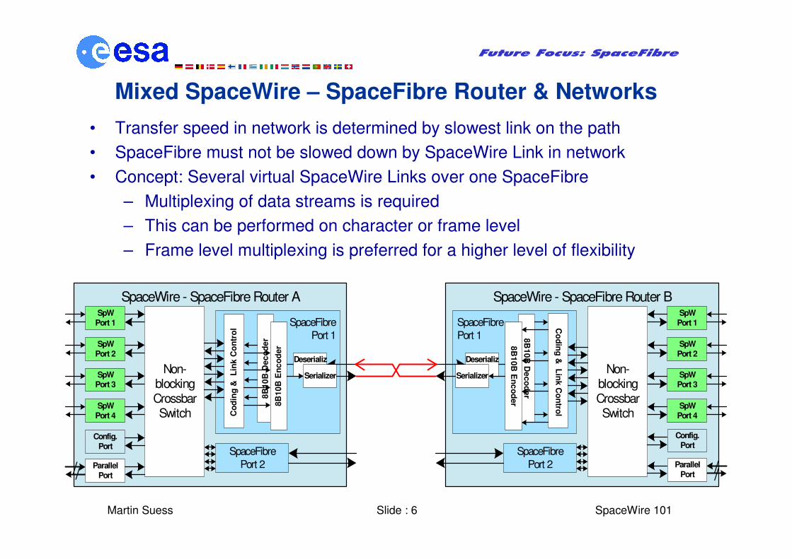
• Mixed SpaceWire – SpaceFibre networks
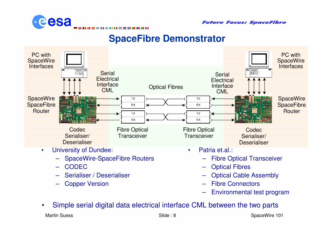
• Demonstrator Development
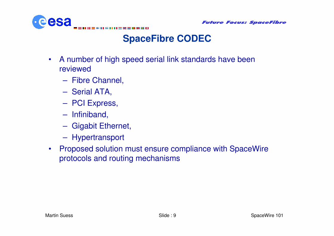
• SpaceFibre Codec
• SpaceFibre Optical Link Technology
• Conclusion
Martin Suess Slide : 3
Future Focus: SpaceFibre
� SpaceWire 101
SpaceWire Limitations
• Link data rate is currently <200-400Mb/s gross
– Limited by jitter and skew between data and strobe signal
– Situation worsens with longer cables length
• SpaceWire link maximum cable length is 10m at high speed
– In general sufficient for on satellite applications
– Other applications like Launchers, Space Station and EGSEs for ground testing could require longer cable length
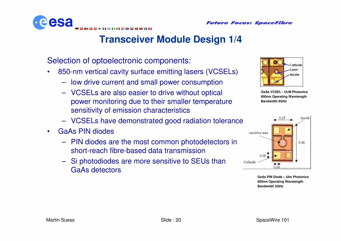
– VCSELs have demonstrated good radiation tolerance
• GaAs PIN diodes
– PIN diodes are the most common photodetectors in
short-reach fibre-based data transmission
– Si photodiodes are more sensitive to SEUs than
GaAs detectors
GsAs VCSEL - ULM Photonics
850nm Operating Wavelength
Bandwidth 6GHz
GaAs PIN Diode – Ulm Photonics
850nm Operating Wavelength
Bandwidth 5GHz
Martin Suess Slide : 21
Future Focus: SpaceFibre
� SpaceWire 101
Transceiver Module Design 2/4
Optical design:
• Low temperature co-fired ceramic (LTCC) substrate technology
• The VCSEL laser chip is aligned with the substrate hole and attached using solder bumps
• The multimode fibre is passively aligned and supported using a precision hole in the five-layer LTCC substrate
• The fibre-to-detector coupling is realized using the same principle
Martin Suess Slide : 22
Future Focus: SpaceFibre
� SpaceWire 101
Transceiver Module Design 3/4
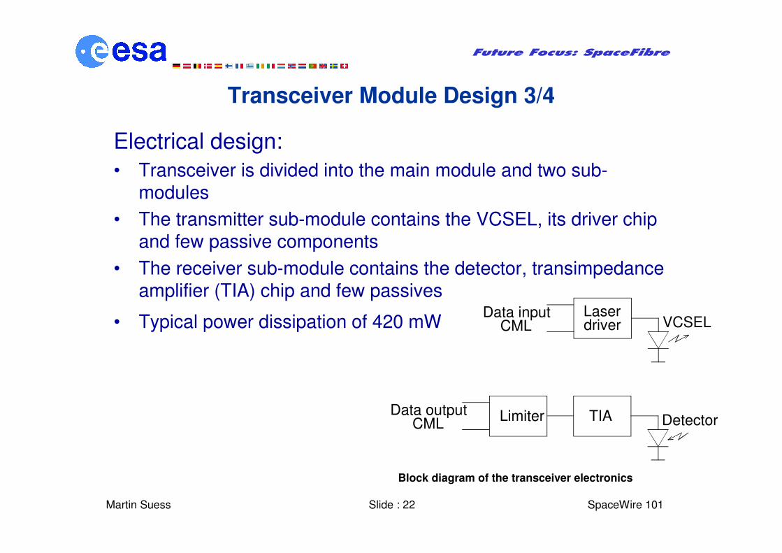
Electrical design:
• Transceiver is divided into the main module and two sub-modules
• The transmitter sub-module contains the VCSEL, its driver chip and few passive components
• The receiver sub-module contains the detector, transimpedanceamplifier (TIA) chip and few passives
• Typical power dissipation of 420 mWLaserdriver
Data inputCML VCSEL
TIAData outputCML DetectorLimiter
Block diagram of the transceiver electronics
Martin Suess Slide : 23
Future Focus: SpaceFibre
� SpaceWire 101
Transceiver Module Design 4/4
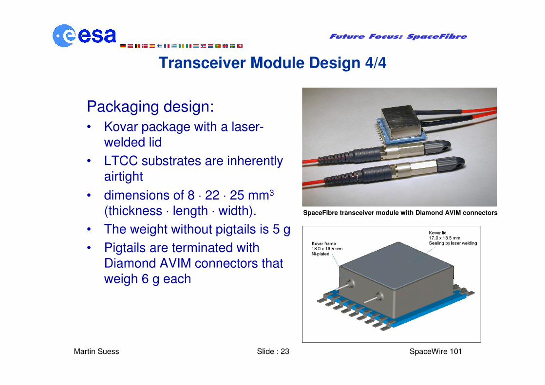
Packaging design:
• Kovar package with a laser-welded lid
• LTCC substrates are inherently airtight
• dimensions of 8 ⋅ 22 ⋅ 25 mm3
(thickness ⋅ length ⋅ width).
• The weight without pigtails is 5 g
• Pigtails are terminated with Diamond AVIM connectors that weigh 6 g each
SpaceFibre transceiver module with Diamond AVIM connectors
Martin Suess Slide : 24
Future Focus: SpaceFibre
� SpaceWire 101
SpaceFibre Environmental Requirements
• Several different missions were reviewed for identifying typicalrequirements to be used as the baseline for the SpaceFibre link specifications:
– Random vibration ≤ 25 grms
– Mechanical shock ≤ 3000 g @ 10 kHz
– Total radiation dose ≤ 100 krad
– Operational temperature −40 ... + 85 °C
– Storage temperature −50 ... + 95 °C
– Mission lifetime up to 15 years
– Non-outgassing materials
Martin Suess Slide : 25
Future Focus: SpaceFibre
� SpaceWire 101
Transceiver Module Testing 1/3
Functional testing:
• The eye diagram at the receiver output
was found to remain acceptable up to 6
Gbps
• BER testing at 2.5 Gbps showed that with
99% confidence BER is better than
1.3 · 10-14. - No errors were detected
during the measurement period, so the
BER result is expected to improve in
measurements with longer duration
• The SpaceFibre link was proved to have
an optical power budget margin of at least
15 dB
Eye diagram of the 3.125 Gbps PRBS
at the receiver output
Martin Suess Slide : 26
Future Focus: SpaceFibre
� SpaceWire 101
Transceiver Module Testing 2/3
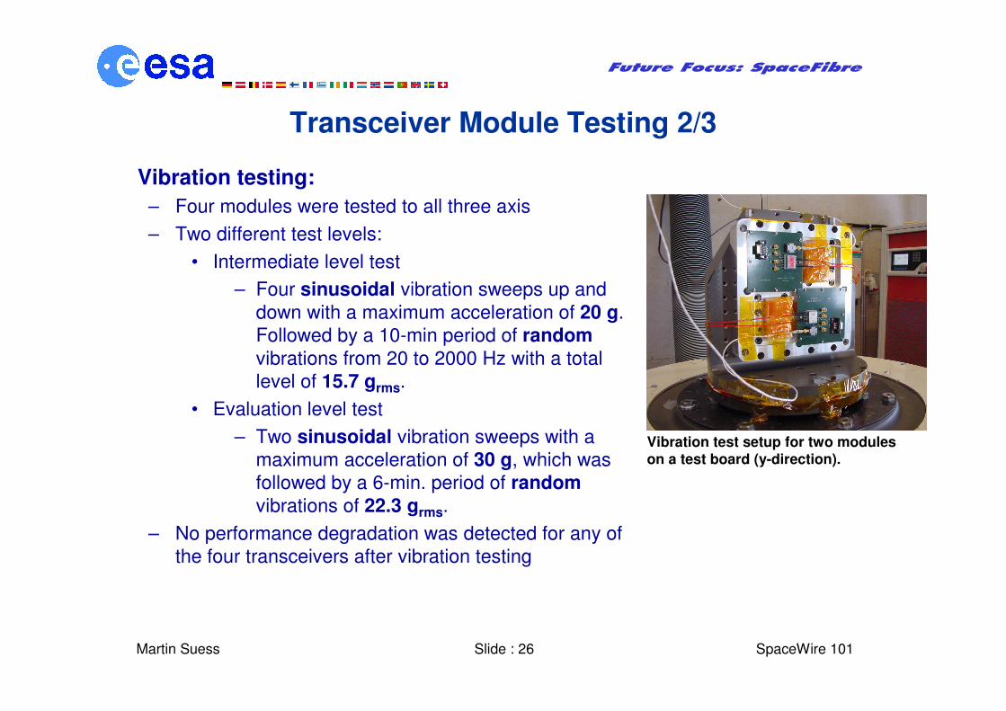
Vibration testing:
– Four modules were tested to all three axis
– Two different test levels:
• Intermediate level test
– Four sinusoidal vibration sweeps up and
down with a maximum acceleration of 20 g.
Followed by a 10-min period of random
vibrations from 20 to 2000 Hz with a total
level of 15.7 grms.
• Evaluation level test
– Two sinusoidal vibration sweeps with a
maximum acceleration of 30 g, which was
followed by a 6-min. period of random
vibrations of 22.3 grms.
– No performance degradation was detected for any of
the four transceivers after vibration testing
Vibration test setup for two moduleson a test board (y-direction).
Martin Suess Slide : 27
Future Focus: SpaceFibre
� SpaceWire 101
Transceiver Module Testing 3/3
Thermal cycling:
– Two modules were subjected to a test campaign of 2 x 40 cycles in
air circulating chamber from -40°C to +85°C.
– The average duration of min. and max. temperature levels for each
cycle was 15 minutes
– Modules were operational throughout the testing, transmitting BER
test data at 2.0 Gbps to both directions
– The maximum degradation of module power budget was in the
order of -4 dB at + 85°C.
– At -40°C the performance degradation was negligible
Radiation testing is ongoing but looks very promising
Shock testing:
– Three modules were tested to all three axis
– Impacts with peaks from 2900 to 3900 g were used
– All modules were found to be operational after the shock impacts.
– One module showed slight degradation in performance
Martin Suess Slide : 28
Future Focus: SpaceFibre
� SpaceWire 101
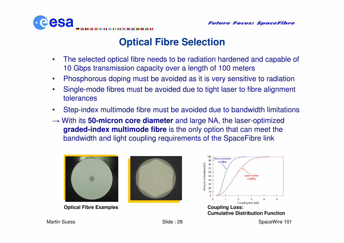
Optical Fibre Selection
• The selected optical fibre needs to be radiation hardened and capable of
10 Gbps transmission capacity over a length of 100 meters
• Phosphorous doping must be avoided as it is very sensitive to radiation
• Single-mode fibres must be avoided due to tight laser to fibre alignment
tolerances
• Step-index multimode fibre must be avoided due to bandwidth limitations
→ With its 50-micron core diameter and large NA, the laser-optimized
graded-index multimode fibre is the only option that can meet the
bandwidth and light coupling requirements of the SpaceFibre link
Optical Fibre Examples Coupling Loss:Cumulative Distribution Function
Martin Suess Slide : 29
Future Focus: SpaceFibre
� SpaceWire 101
Optical Fibre Testing
• Radiation can introduce darkening of the fibre
• Radiation hardness of several COTS laser-optimized graded-index multimode fibres were determined
• Measurements of the radiation-induced attenuation show losses varying from 7 to 16 dB when the 100 m long fibres are exposed to a dose rate of 45 krad/h and for a total irradiation dose of 100 krad
• When considering the typical dose rates in space, radiation-induced attenuation losses can be as low as 0.05 to 1 dB
• Draka MaxCap 300 radhard-optimized fibre, the best performing fibre was selected for the SpaceFibre link
Martin Suess Slide : 30
Future Focus: SpaceFibre
� SpaceWire 101
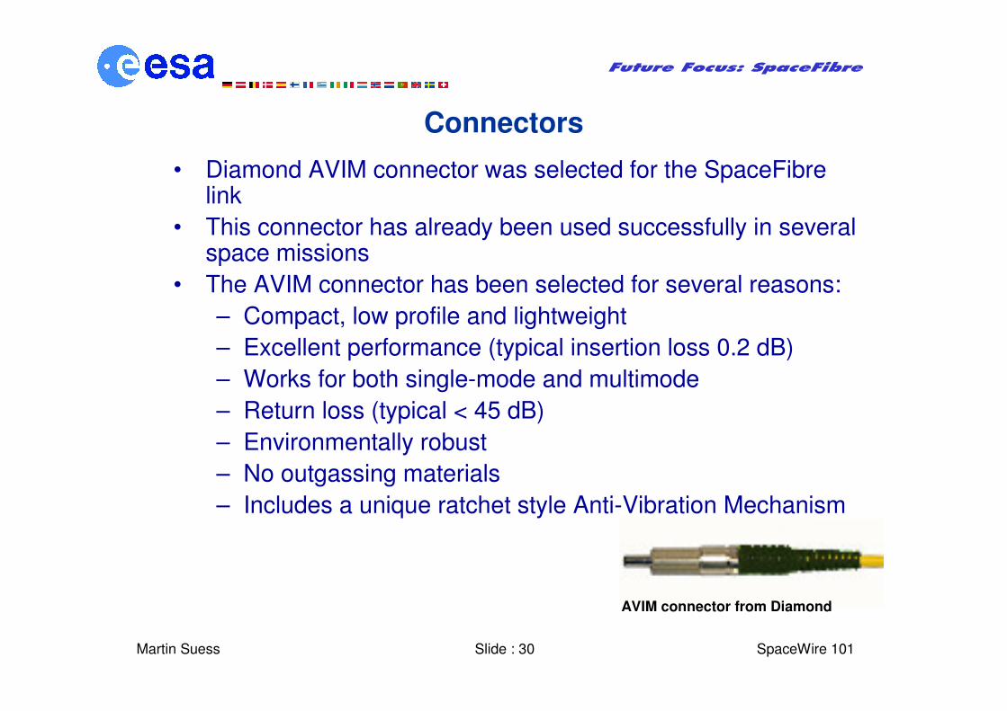
Connectors
• Diamond AVIM connector was selected for the SpaceFibre link
• This connector has already been used successfully in several space missions
• The AVIM connector has been selected for several reasons:
– Compact, low profile and lightweight
– Excellent performance (typical insertion loss 0.2 dB)
– Works for both single-mode and multimode
– Return loss (typical < 45 dB)
– Environmentally robust
– No outgassing materials
– Includes a unique ratchet style Anti-Vibration Mechanism
AVIM connector from Diamond
Martin Suess Slide : 31
Future Focus: SpaceFibre
� SpaceWire 101
Cable Design
• Cables from W. L. Gore were selected for the
SpaceFibre link
• Due to the wide operational temperature ranges
in space, thermally-induced microbending is a
real phenomenon to be managed
• An expanded polytetrafluoethylene (ePTFE)
buffering system can minimize microbend-
induced attenuation changes
• W. L. Gore design incorporates a layer of ePTFE
directly over the coated fibre
• This layer significantly mitigates the variation of
coefficient of thermal expansion (CTE) effects
between the fibre and the other layers
SpaceFibre cable schematics
Martin Suess Slide : 32
Future Focus: SpaceFibre
� SpaceWire 101
Conclusions
• SpaceFibre was investigated as the fibre optical extension to the SpaceWire
standard
• SpaceFibre will be able to cover the very high data rate applications while being
in line with the SpaceWire developments
• The copper version of SpaceFibre is intended to cover shorter distances in
particular application areas
• System requirements together with CODEC and optical technology trades-offs
were presented
• CODEC and optical transceiver design where shown
• Environmental testing results for the optical technology where reported
• A demonstrator has been developed within the SpaceFibre activity to show a
mixed SpaceWire – SpaceFibre network
• The demonstrator can serve as test bed for a standardisation to be initiated in the