Page 1
School of Science & Technology Engineering
B.Eng(Hons) Aeronautical & Mechanical Engineering
Final Year Project Report 40 Credits
Future Propulsion Systems Alternative Fuels
Name: Albert Jordà i Juanós Supervisor: Robert Parry Date: May 2008
Page 3
FUTURE PROPULSION SYSTEMS Albert Jordà
ABSTRACT
Freedom involves transports. In the current society people want to be able to travel
around the world. Tourism, student exchange programs, visits to family or friends living
abroad, business, and many other facts could be a reason to move by plane.
The air traffic experimented a progressive grow during the last years, and the prediction
is that it will still continue increasing. However, there are two main problems which
could act as hindrances against such process of development.
On the one hand, the majority of engines that are being used to propel aircraft nowadays
work burning fossil oil derivative fuels. Oil is a limited raw material the value of which
is currently rising due to the fact that it is being exhausted.
On the other hand, the other concern is the emissions produced by the combustion of
such fuels by aircraft engines. The fumes produced remain in the atmosphere
contributing to the greenhouse effect and the global warming, which are two of the
ecological problems that the society must fight against.
These reasons cause the need to research and develop Future Propulsion Systems. In
this project a study of the further possibilities to solve such problems is presented, as
well as a comparison and discussion trying to forecast what could be the best path to
follow, in order to continue propelling aircraft in a greener, more economical and
sustainable way.
Page 4
FUTURE PROPULSION SYSTEMS Albert Jordà
TABLE OF CONTENTS
Page
1. INTRODUCTION......................................................................................6
2. AIMS OF PROJECT ................................................................................8
3. REVIEW OF LITERATURE.................................................................9
3.1 Aircraft Historical and Developments ........................................9
3.2 Solar Power ......................................................................................16
3.2.1 Gossamer Penguin................................................................16 3.2.2 Solar Challenger...................................................................17 3.2.3 Pathfinder (1981 to 1997) .....................................................18 3.2.4 Pathfinder Plus (1998 to 2005).............................................19 3.2.5 Centurion (1996 to 1998)......................................................19 3.2.6 Helios (1998 to 2003) ............................................................20
3.3 Nuclear Power .................................................................................22
3.4 Biomass Power ................................................................................25
3.5 Battery/Fuel Cell Power ................................................................28
3.6 Hydrogen Engines Power ..............................................................33
3.6.1 Combustion Hazard .............................................................33 3.6.2 Pressure Hazard ...................................................................34 3.6.3 Hydrogen-Related Injuries ..................................................34
4. RESULTS AND DISCUSSION..............................................................39
4.1 Solar Power ......................................................................................39
4.2 Nuclear Power .................................................................................39
4.3 Biomass Power ................................................................................40
4.4 Battery/Fuel Cell Power ................................................................41
4.5 Hydrogen Engines Power ..............................................................41
4.6 Discussion ........................................................................................43
5. CONCLUSIONS.........................................................................................48
6. RECOMMENDATIONS .........................................................................50
7. REFERENCES ...........................................................................................51
Page 5
FUTURE PROPULSION SYSTEMS Albert Jordà
6
1. INTRODUCTION
Since their inception, most aircraft have been powered by oil derived fuels. The current
aircraft propulsion systems are also based on burning oil derivate fuels. There are
several problems scientifically demonstrated that highly recommend changing the
systems used by others.
Oil is a limited raw material and it is currently running out. The studies say that the oil
discovered 40 years ago is the basis of current oil production. And although almost all
the oil fields have already been discovered, countries in process of development (i.e.
some Asian countries) are expected to increase their oil consumption in the next years.
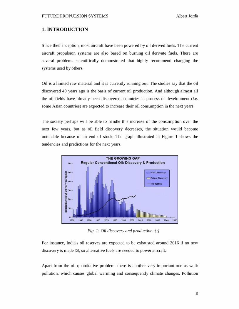
The society perhaps will be able to handle this increase of the consumption over the
next few years, but as oil field discovery decreases, the situation would become
untenable because of an end of stock. The graph illustrated in Figure 1 shows the
tendencies and predictions for the next years.
For instance, India's oil reserves are expected to be exhausted around 2016 if no new
discovery is made [2], so alternative fuels are needed to power aircraft.
Apart from the oil quantitative problem, there is another very important one as well:
pollution, which causes global warming and consequently climate changes. Pollution
Fig. 1: Oil discovery and production. [1]
Page 6
FUTURE PROPULSION SYSTEMS Albert Jordà
7
from aircraft burning kerosene fuel contributes, among others, towards greenhouse gas
emissions and analysts estimate that aircraft account for between 6-10% of these
emissions. Global warming is currently an issue that is the top of most agendas because
of the threat it poses to society, both present and future. This problem should be seen as
a challenge that society is forced to overcome.
There are other technological issues that could improve the current aircraft propulsion
systems. For example, people living in the surrounding area of the airports have to punt
up with and coexist with the high intensity noise from the aircraft engines that are either
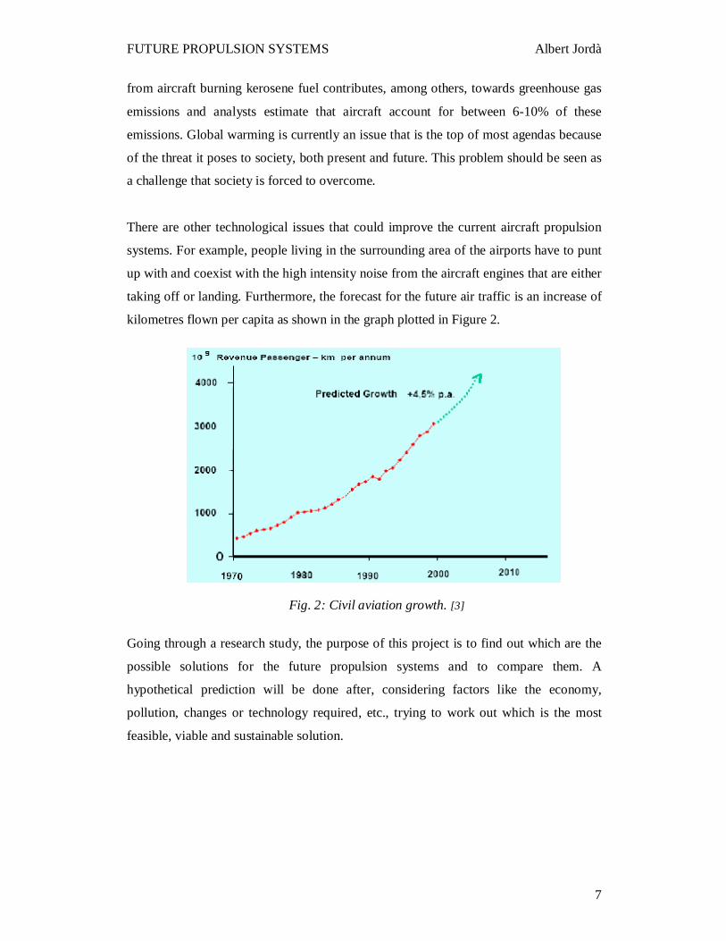
taking off or landing. Furthermore, the forecast for the future air traffic is an increase of
kilometres flown per capita as shown in the graph plotted in Figure 2.
Going through a research study, the purpose of this project is to find out which are the
possible solutions for the future propulsion systems and to compare them. A
hypothetical prediction will be done after, considering factors like the economy,
pollution, changes or technology required, etc., trying to work out which is the most
feasible, viable and sustainable solution.
Fig. 2: Civil aviation growth. [3]
Page 7
FUTURE PROPULSION SYSTEMS Albert Jordà
8
2. AIMS OF THE PROJECT
As it has been mentioned in section one, the current aircraft engines use oil derivative
fuels to supply the necessary thrust required to fly. It is also known that the oil is going
to be exhausted soon. Here, there is the reason for being of the project Future
Propulsion Systems.
It is obvious that the aeronautical world needs changes in terms of propulsion or energy
to become independent of oil. The main aim of the project is to expose and study the
possible solutions to this problem, as well as try to forecast the path that could be
followed in order to make the aircraft propulsion systems more and more efficient,
cleaner, economical and oil independent.
After demonstrating that changes are required and different energy sources or
propulsion systems are needed, the first aim is to list and explain, in as much detail as
possible, the solutions that the current science and technology is treating, researching
and developing or even able to supply. Note that according to the characteristics of the
possible solutions, they may be short or long term. Provisional alternative fuels that may
help the process of becoming oil independent are also to be considered and the trends
followed by the most important engine companies will be analysed too.
The next step will be a comparative analysis among the systems or solutions described
in the previous step. The factors to be analysed are the advantages and disadvantages
with regard to the view point of the economy, pollution, changes or technology
required, feasibility and sustainability. The noise produced in the engines is also an
issue. Therefore, the noise will also be considered in the analysis in the cases in which
such information is taken into account.
Finally, after being able to forecast a hypothetical solution, an argument and discussion
of why such a new system would be the best to replace the current systems will be
exposed. The main issues, features and contributions or improvements that it would
provide, with regard to the factors mentioned before (economy, pollution,
technology…) will also be explained.
Page 8
FUTURE PROPULSION SYSTEMS Albert Jordà
9
3. REVIEW OF LITERATURE
In this section an overview of the aeronautical improvement trends of the last century
will be exposed. An analysis of the current engines situation will be done. After that, a
list of new possible solutions will be described.
3.1 Aircraft Historical and Developments
With the aim of the reduction expenses and improvement in aircraft performance, many
changes have been introduced. However, there is still the potential to improve more,
acting for example on:
• The aircraft technology.
• The airframe and engines.
• The fuel.
• The operational activity.
Rules and economy could also improve the efficiency of the processes in regard to the
aircraft engines. Improving the factors governing these issues (which are basically the
systems’ efficiencies) could result in a more sustainable, non polluting, economical and
oil independent aircraft propulsion.
Major advances in aircraft technology have been achieved in the past 40-50 years. Over
that period, principal methods of propulsion have changed: Propeller aircraft were
succeeded by jet-powered aircraft of the 1950s; these jets, in turn, were superseded by
turbofan-powered aircraft from 1970 onwards. The fleet has expanded rapidly. So too
has the capacity of jet aircraft-rising from typical 150-seat versions of the late 1950s to
the 800-seat variant of the A380. The performance and capability of aircraft has also
changed greatly. Cruise speeds of propeller aircraft have trebled from the 185 km/h
typical of the 1940s. At the start of the commercial jet age, speeds rose to 830 km/h.
Today's turbofans cruise at average speeds of around 926 km/h. The search for efficient
cruise performance with greater range, particularly for long-haul aircraft, has also
resulted in higher flying aircraft, a key factor in determining where most aircraft
emissions occur and their resulting. Average cruise altitudes for propeller aircraft rose
Page 9
FUTURE PROPULSION SYSTEMS Albert Jordà
10
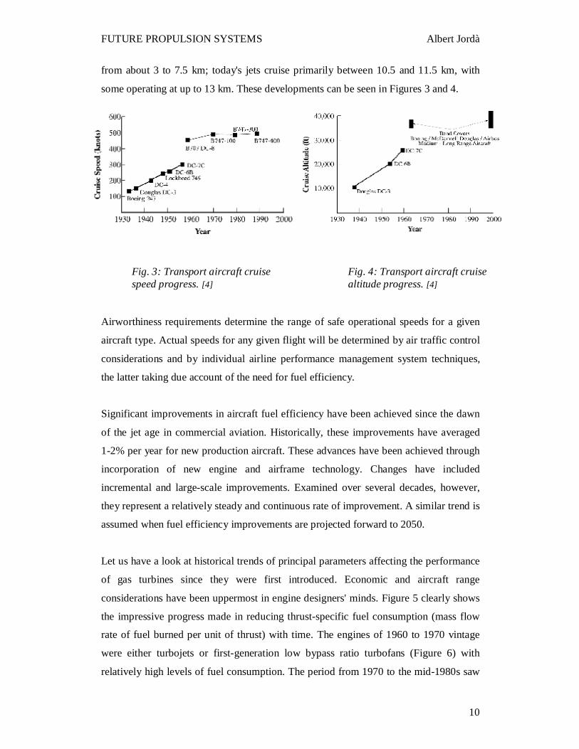
from about 3 to 7.5 km; today's jets cruise primarily between 10.5 and 11.5 km, with
some operating at up to 13 km. These developments can be seen in Figures 3 and 4.
Airworthiness requirements determine the range of safe operational speeds for a given
aircraft type. Actual speeds for any given flight will be determined by air traffic control
considerations and by individual airline performance management system techniques,
the latter taking due account of the need for fuel efficiency.
Significant improvements in aircraft fuel efficiency have been achieved since the dawn
of the jet age in commercial aviation. Historically, these improvements have averaged
1-2% per year for new production aircraft. These advances have been achieved through
incorporation of new engine and airframe technology. Changes have included
incremental and large-scale improvements. Examined over several decades, however,
they represent a relatively steady and continuous rate of improvement. A similar trend is
assumed when fuel efficiency improvements are projected forward to 2050.
Let us have a look at historical trends of principal parameters affecting the performance
of gas turbines since they were first introduced. Economic and aircraft range
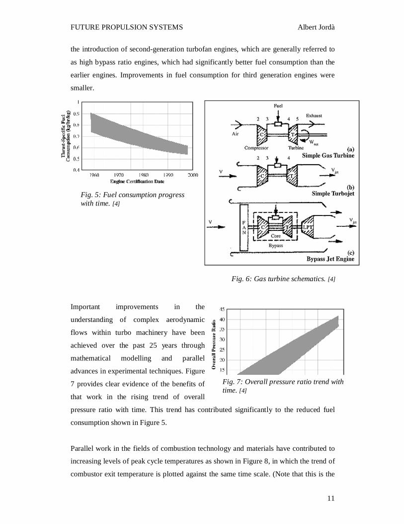
considerations have been uppermost in engine designers' minds. Figure 5 clearly shows
the impressive progress made in reducing thrust-specific fuel consumption (mass flow
rate of fuel burned per unit of thrust) with time. The engines of 1960 to 1970 vintage
were either turbojets or first-generation low bypass ratio turbofans (Figure 6) with
relatively high levels of fuel consumption. The period from 1970 to the mid-1980s saw
Fig. 3: Transport aircraft cruise speed progress. [4]
Fig. 4: Transport aircraft cruise altitude progress. [4]
Page 10
FUTURE PROPULSION SYSTEMS Albert Jordà
11
the introduction of second-generation turbofan engines, which are generally referred to
as high bypass ratio engines, which had significantly better fuel consumption than the
earlier engines. Improvements in fuel consumption for third generation engines were
smaller.
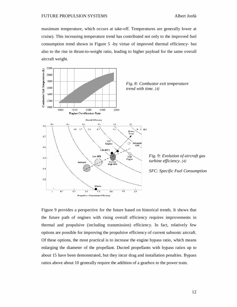
Important improvements in the
understanding of complex aerodynamic
flows within turbo machinery have been
achieved over the past 25 years through
mathematical modelling and parallel
advances in experimental techniques. Figure
7 provides clear evidence of the benefits of
that work in the rising trend of overall
pressure ratio with time. This trend has contributed significantly to the reduced fuel
consumption shown in Figure 5.
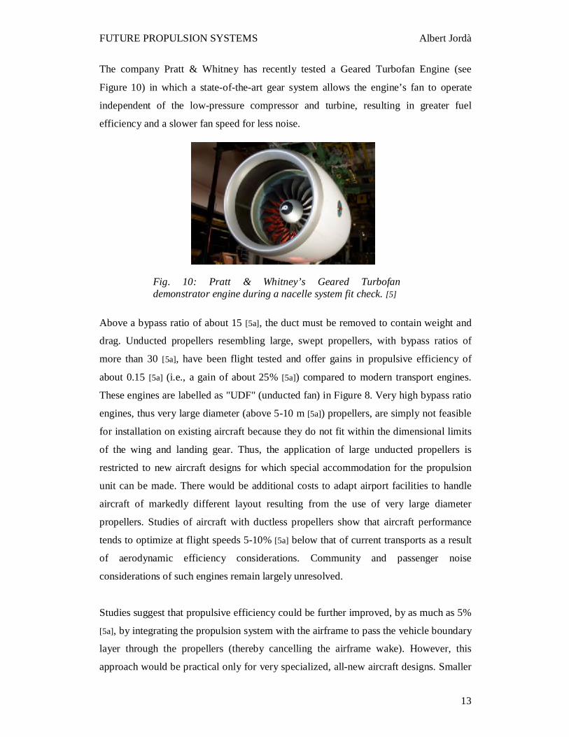
Parallel work in the fields of combustion technology and materials have contributed to
increasing levels of peak cycle temperatures as shown in Figure 8, in which the trend of
combustor exit temperature is plotted against the same time scale. (Note that this is the
Fig. 5: Fuel consumption progress with time. [4]
Fig. 7: Overall pressure ratio trend with time. [4]
Fig. 6: Gas turbine schematics. [4]
Page 11
FUTURE PROPULSION SYSTEMS Albert Jordà
12
maximum temperature, which occurs at take-off. Temperatures are generally lower at
cruise). This increasing temperature trend has contributed not only to the improved fuel
consumption trend shown in Figure 5 -by virtue of improved thermal efficiency- but
also to the rise in thrust-to-weight ratio, leading to higher payload for the same overall
aircraft weight.
Figure 9 provides a perspective for the future based on historical trends. It shows that
the future path of engines with rising overall efficiency requires improvements in
thermal and propulsive (including transmission) efficiency. In fact, relatively few
options are possible for improving the propulsive efficiency of current subsonic aircraft.
Of these options, the most practical is to increase the engine bypass ratio, which means
enlarging the diameter of the propellant. Ducted propellants with bypass ratios up to
about 15 have been demonstrated, but they incur drag and installation penalties. Bypass
ratios above about 10 generally require the addition of a gearbox to the power train.
Fig. 8: Combustor exit temperature trend with time. [4]
Fig. 9: Evolution of aircraft gas turbine efficiency. [4] SFC: Specific Fuel Consumption
Page 12
FUTURE PROPULSION SYSTEMS Albert Jordà
13
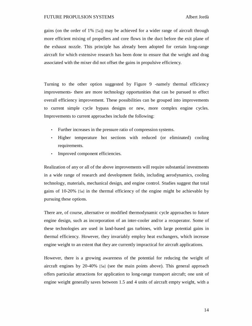
The company Pratt & Whitney has recently tested a Geared Turbofan Engine (see
Figure 10) in which a state-of-the-art gear system allows the engine’s fan to operate
independent of the low-pressure compressor and turbine, resulting in greater fuel
efficiency and a slower fan speed for less noise.
Above a bypass ratio of about 15 [5a], the duct must be removed to contain weight and
drag. Unducted propellers resembling large, swept propellers, with bypass ratios of
more than 30 [5a], have been flight tested and offer gains in propulsive efficiency of
about 0.15 [5a] (i.e., a gain of about 25% [5a]) compared to modern transport engines.
These engines are labelled as "UDF" (unducted fan) in Figure 8. Very high bypass ratio
engines, thus very large diameter (above 5-10 m [5a]) propellers, are simply not feasible
for installation on existing aircraft because they do not fit within the dimensional limits
of the wing and landing gear. Thus, the application of large unducted propellers is
restricted to new aircraft designs for which special accommodation for the propulsion
unit can be made. There would be additional costs to adapt airport facilities to handle
aircraft of markedly different layout resulting from the use of very large diameter
propellers. Studies of aircraft with ductless propellers show that aircraft performance
tends to optimize at flight speeds 5-10% [5a] below that of current transports as a result
of aerodynamic efficiency considerations. Community and passenger noise
considerations of such engines remain largely unresolved.
Studies suggest that propulsive efficiency could be further improved, by as much as 5%
[5a], by integrating the propulsion system with the airframe to pass the vehicle boundary
layer through the propellers (thereby cancelling the airframe wake). However, this
approach would be practical only for very specialized, all-new aircraft designs. Smaller
Fig. 10: Pratt & Whitney’s Geared Turbofan demonstrator engine during a nacelle system fit check. [5]
Page 13
FUTURE PROPULSION SYSTEMS Albert Jordà
14
gains (on the order of 1% [5a]) may be achieved for a wider range of aircraft through
more efficient mixing of propellers and core flows in the duct before the exit plane of
the exhaust nozzle. This principle has already been adopted for certain long-range
aircraft for which extensive research has been done to ensure that the weight and drag
associated with the mixer did not offset the gains in propulsive efficiency.
Turning to the other option suggested by Figure 9 -namely thermal efficiency
improvements- there are more technology opportunities that can be pursued to effect
overall efficiency improvement. These possibilities can be grouped into improvements
to current simple cycle bypass designs or new, more complex engine cycles.
Improvements to current approaches include the following:
• Further increases in the pressure ratio of compression systems.
• Higher temperature hot sections with reduced (or eliminated) cooling
requirements.
• Improved component efficiencies.
Realization of any or all of the above improvements will require substantial investments
in a wide range of research and development fields, including aerodynamics, cooling
technology, materials, mechanical design, and engine control. Studies suggest that total
gains of 10-20% [5a] in the thermal efficiency of the engine might be achievable by
pursuing these options.
There are, of course, alternative or modified thermodynamic cycle approaches to future
engine design, such as incorporation of an inter-cooler and/or a recuperator. Some of
these technologies are used in land-based gas turbines, with large potential gains in
thermal efficiency. However, they invariably employ heat exchangers, which increase
engine weight to an extent that they are currently impractical for aircraft applications.
However, there is a growing awareness of the potential for reducing the weight of
aircraft engines by 20-40% [5a] (see the main points above). This general approach
offers particular attractions for application to long-range transport aircraft; one unit of
engine weight generally saves between 1.5 and 4 units of aircraft empty weight, with a
Page 14
FUTURE PROPULSION SYSTEMS Albert Jordà
15
concomitant decrease in fuel burn. Enabling technologies required to achieve significant
engine weight reductions include the following:
• Improved materials (composites and high-temperature materials in particular).
• Improved aerodynamics (to reduce the number of turbine and compressor
stages).
• Increased turbine entry temperatures (to reduce airflow thus core engine size
required for a given power output).
None of these options is new to manufacturers, who already have research and
development programs addressing these subjects aimed at civil and military aircraft of
the future. As always, progress and success in meeting these objectives is paced by the
scale of investment by industry and/or government supporting the work.
Several other energy conversion technologies have been identified that may have
potential for application in commercial aircraft (e.g., solar power, nuclear power,
biomass power, battery/fuel cell power, and hydrogen engines). Although given the
current state of technology, there are simply no other energy conversion systems
identified to date that can offer competitive levels of thermal efficiency and power-to-
weight ratio for aircraft propulsion, these advanced concepts are in the aircraft engines
companies’ research and development engineers’ minds.
These systems would require major innovations, development, and perhaps changes in
infrastructure before they could serve as viable alternatives to hydrocarbon-powered gas
turbine engines, but they are starting to be studied, for example, by Airbus, Boeing,
Pratt & Whitney, General Electrics, Rolls-Royce, etc. They are investing on this kind of
systems because of their potential. These further energy conversion systems will be
exposed and analysed in the next sections. Different projects that were done in the past
or are currently in process will also be presented. Some of the current projects are taking
part in the Framework 6 programme, which is the European Community Framework
Programme for Research, Technological Development and Demonstration. It is a
collection of the actions at EU level to fund and promote research.
Page 15
FUTURE PROPULSION SYSTEMS Albert Jordà
16
3.2 Solar Power
The strategy in this case is to assemble solar panels that would take part of the aircraft
body and skin. Normally the panels are located on the wings, where there is a more
uniform surface and it is easier to assemble. The aim is to obtain electrical energy from
the panels and use it to propel the aircraft. However, since this system is still not very
efficient, it is basically used in study prototype aircrafts with very lightweight
characteristics. If the efficiency of the panels is not increased, this system would be used
just to supply extra energy for other aircraft systems instead of supplying propulsion
energy.
Some aircraft models like the Flying Wing have higher surface in where allocate solar
panels. This fact could be considered as favourable because then more energy would be
supplied.
Different airplanes are able to fly at altitudes of 30000 m with a payload of about 45 kg
(or more with less altitude).
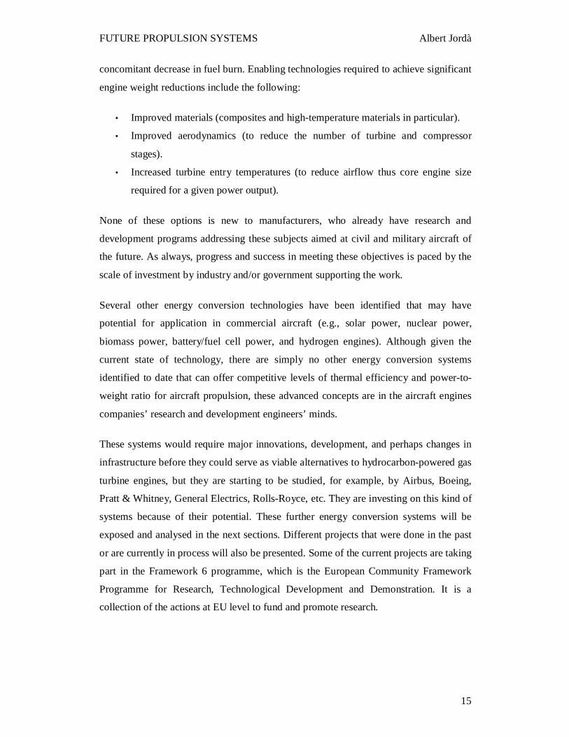
3.2.1 Gossamer Penguin
The scaled-down aircraft was designated the Gossamer Penguin (Figure 11). It had a 71
ft wingspan. Weighing only 30.84 kg without a pilot, it had a low power requirement
and thus was an excellent test bed for solar power.
Fig. 11: The Gossamer Penguin. [6]
Page 16
FUTURE PROPULSION SYSTEMS Albert Jordà
17
The power source for the initial flights of the Gossamer Penguin consisted of 28 nickel-
cadmium batteries, replaced for the solar-powered flights by a panel of 3,920 solar cells
capable of producing 541 Watts of power.
Wind direction, turbulence, convection, temperature and radiation in mid-summer
proved to be less than ideal for Gossamer Penguin because takeoffs required no
crosswind and increases in temperature reduced the power output from the solar cells.
Nevertheless, Janice flew a public demonstration of the aircraft in which it went roughly
1.95 miles in 14 minutes and 21 seconds.
This was significant as the first sustained flight of an aircraft relying solely on direct
solar power rather than batteries. It provided the designers with practical experience for
developing a more advanced, solar-powered aircraft, since the Gossamer Penguin was
fragile and had limited controllability. This necessitated its flying early in the day when
there were minimal wind and turbulence levels, but the angle of the sun was also low,
requiring a panel for the solar cells that could be tilted toward the sun.
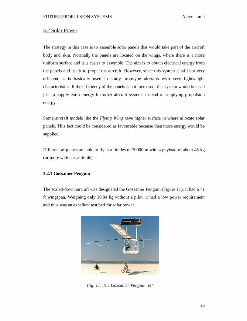
3.2.2 Solar Challenger
Using the specific conclusions derived from their experience with Gossamer Penguin,
the AeroVironment engineers designed Solar Challenger (Figure 12), a piloted, solar-
powered aircraft strong enough to handle both long and high flights when encountering
normal turbulence. As compared with the Penguin's 71-foot wingspan, Solar Challenger
had only a 46.5-foot wingspan, but it had a huge horizontal stabilizer and a large enough
wing area to accommodate 16,128 solar cells.
Fig. 12: The Solar Challenger. [6]
Page 17
FUTURE PROPULSION SYSTEMS Albert Jordà
18
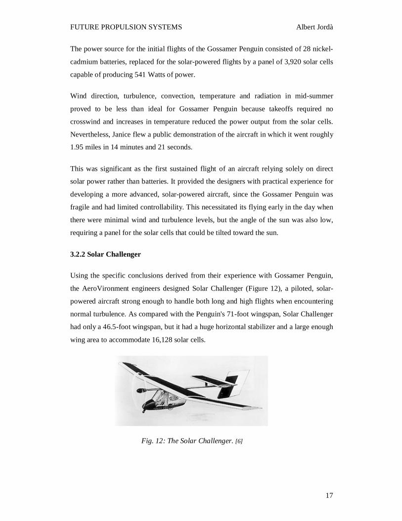
3.2.3 Pathfinder (1981 to 1997)
Inspired by the possibilities of their earlier manned solar-powered aircraft, Aero
Vironment first began developing a solar-powered HALE UAV in 1981 to provide a
continuous high altitude (Figure 13) platform. After making 9 successful test flights, the
99 ft wingspan Pathfinder was mothballed for a decade because of technology limits in
the propulsion system at that time. The Pathfinder aircraft was then adopted by NASA's
Environmental Research Aircraft and Sensor Technology (ERAST) program in 1994, to
assist in the development of research platforms for the Stratosphere. Pathfinder flew to
50567 feet (15.4 km) at Edwards September 12, 1995, its first trip to the stratosphere.
From there, it was improved and taken to the Pacific Missile Range Facility (PMRF),
Kauai, Hawaii for test flights in 1997, where it flew to 71504 feet (21.8 km) on July 7,
before performing a series of science missions over the Hawaiian Islands.
Fig. 13: The Pathfinder. [6]
Page 18
FUTURE PROPULSION SYSTEMS Albert Jordà
19
3.2.4 Pathfinder Plus (1998 to 2005)
In 1998, Pathfinder was upgraded to become the Pathfinder Plus, with a new center
wing panel, which increased the wingspan to 121 ft. New high-efficiency solar cells
were fitted and many other improvements made, before making a maiden flight in June.
On August 6, 1998, Pathfinder Plus met its intended goal by flying to a record 80201 ft,
higher than any other previous propeller-driven aircraft. The Pathfinder Plus was flown
on telecommunication missions in June 2002, and again for aerial surveillance of coffee
crops in September. Later in 2002, Pathfinder Plus performed the world's first telecom
demonstrations from 65000 ft (20km), including high-definition television (HDTV)
broadcasts, third-generation (3G) mobile voice, video, and data relays using an off-the-
shelf mobile handset, and high speed internet connection. Most recently, Pathfinder Plus
was flown at Edwards AFB to perform atmospheric turbulence measurements in August
and September 2005, before being retired from flight service.
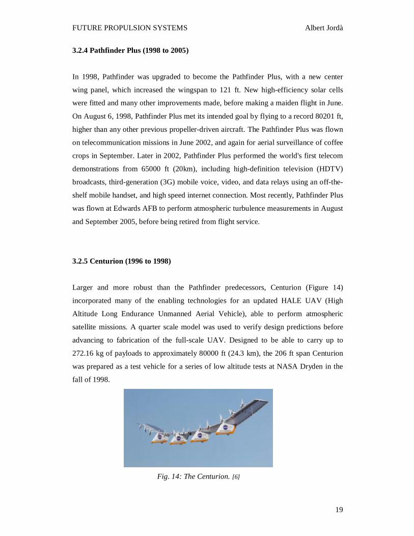
3.2.5 Centurion (1996 to 1998)
Larger and more robust than the Pathfinder predecessors, Centurion (Figure 14)
incorporated many of the enabling technologies for an updated HALE UAV (High
Altitude Long Endurance Unmanned Aerial Vehicle), able to perform atmospheric
satellite missions. A quarter scale model was used to verify design predictions before
advancing to fabrication of the full-scale UAV. Designed to be able to carry up to
272.16 kg of payloads to approximately 80000 ft (24.3 km), the 206 ft span Centurion
was prepared as a test vehicle for a series of low altitude tests at NASA Dryden in the
fall of 1998.
Fig. 14: The Centurion. [6]
Page 19
FUTURE PROPULSION SYSTEMS Albert Jordà
20
Aircraft Specifications summary [6]:
• Wingspan: Solar Challenger, 46.5 feet (14.8 meters); Pathfinder, 98.4 feet (29.5 meters); Pathfinder-Plus, 121 feet (36.3 meters) Centurion, 206 feet (61.8 meters)
• Length: Solar Challenger, 30.3 feet (9.22 meters); Pathfinder, Pathfinder-Plus, and Centurion, 12 feet (3.6 meters)
• Wing chord: Solar Challenger, 5.8 feet (1.78 meters); Pathfinder, Pathfinder-Plus, and Centurion, 8 feet (2.4 meters)
• Gross weight: Solar Challenger, about 336 pounds (152.8 kg); Pathfinder, about 560 pounds (252 kg.); Pathfinder-Plus, about 700 pounds (315 kg.) Centurion, varies depending on power availability and mission profile; approximately 1,900 pounds for a mission to 80,000 feet altitude.
• Payload: Solar Challenger, weight of pilot, up to 150 pounds Pathfinder, up to 100 pounds (45 kg.); Pathfinder-Plus, up to 150 pounds (67.5 kg.) Centurion, varies depending on altitude; about 100 pounds. to 100,000 ft., 600 pounds. to 80,000 feet.
• Airspeed: Solar Challenger, approx. 25-34 mph cruise Pathfinder, Pathfinder -Plus. approx. 17-20 mph cruise Centurion, approx. 17-21 mph cruise
• Power: Arrays of solar cells, max. output: Solar Challenger, 2700 Watts Pathfinder, about 7500 Watts; Pathfinder-Plus, about 12500 Watts Centurion, 31000 Watts
• Motors: Solar Challenger, one electric motor, 2.7 kW Pathfinder, six electric motors, 1.25 kW each Pathfinder-Plus, eight electric motors, 1.5 kW maximum each Centurion, 14 electric motors, 2.2 kW each
• Manufacturer: AeroVironment, Inc. • Primary materials: Composites, plastic, foam.
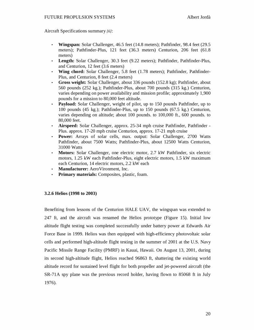
3.2.6 Helios (1998 to 2003)
Benefiting from lessons of the Centurion HALE UAV, the wingspan was extended to
247 ft, and the aircraft was renamed the Helios prototype (Figure 15). Initial low
altitude flight testing was completed successfully under battery power at Edwards Air
Force Base in 1999. Helios was then equipped with high-efficiency photovoltaic solar
cells and performed high-altitude flight testing in the summer of 2001 at the U.S. Navy
Pacific Missile Range Facility (PMRF) in Kauai, Hawaii. On August 13, 2001, during
its second high-altitude flight, Helios reached 96863 ft, shattering the existing world
altitude record for sustained level flight for both propeller and jet-powered aircraft (the
SR-71A spy plane was the previous record holder, having flown to 85068 ft in July
1976).
Page 20
FUTURE PROPULSION SYSTEMS Albert Jordà
21
This historic milestone, reaching well above the planned operational altitude of 65000
ft, further demonstrated the viability for stratospheric platform technology in support of
government and commercial applications.
Apart from those solar aircraft models, High Altitude Airship (HAA), an unmanned
lighter-than-air vehicle, is expected to be covered with thin-film solar arrays for the
propulsion power supply. The vehicle will operate above the jet stream in a quasi-
geostationary position to deliver persistent station keeping as a surveillance platform,
telecommunications relay, or weather observer.
Fig. 15: The Helios. [6]
Page 21
FUTURE PROPULSION SYSTEMS Albert Jordà
22
3.3 Nuclear Power
The nuclear propulsion was researched after World War II, and the investigators
demonstrated that there was a potential interest in it. However, they had a lot of
managing problems and the projects were never actually developed. Furthermore, some
of the other basic problems were the possible release of radioactive fission products or
isotopes during normal operation or due to any accident, shielding the crew and persons
on the ground from radiation, and the selection of test sites and ranges. There was the
potential for the release of radioactive materials to the atmosphere and the problems of
direct radiation during operational use. The requirements for an operational nuclear
aircraft were that, even under the most adverse conditions, the aircraft did not add
materially to the general background atmospheric radioactivity and that while in use the
aircraft restricted all harmful radiation to within the craft or a predesignated exclusion
area.
At that time, they were studying two possibilities: direct and indirect air cycle.
In the direct air cycle air enters through the compressor stage of one or more turbojets.
From there the air passes through a plenum and is directed through the reactor core.
(The plenum is a section of duct work in a forced air system. The area from the forced
air system to the home is called the supply plenum. The area from the home to the
forced air system is called the return plenum). The air, acting as the reactor coolant, is
rapidly heated as it travels through the core. After passing through the reactor the air
passes through another plenum and is directed to the turbine section of the turbojet(s)
and from there out through the tailpipe. An indirect system is very similar, except that
the air does not pass through the reactor itself. After passing through the compressor the
air passes through a heat exchanger. The heat generated by the reactor is carried by a
working fluid to this heat exchanger. The air then passes through the turbine and out the
tailpipe as above. The working fluid in the indirect cycle is usually a dense fluid, such
as a liquid metal, or highly pressurized water. This allows more heat energy to be
transfer, thereby increasing the efficiency of the system.
As said previously, either the direct or indirect air cycle projects were never finished at
that moment. The main problems were, first, a lot of nuclear waste of longer half life is
Page 22
FUTURE PROPULSION SYSTEMS Albert Jordà
23
produced, whose disposal becomes hazardous. Secondly, the energetic neutrons
streaming out of the reactor are of grave concern. Owing to their greater penetration
power, a very thick shielding is required to protect the crew. This thick shielding makes
an airplane too heavy to carry other loads or weapons.
In the late 1990s, the scientists at the University of Texas in Dallas made an unexpected
discovery about the hafnium isomer, known as hafnium-178. When the hafnium-178
was bombarded with “soft” X-rays, like the dentists use to examine the teeth, a burst of
gamma rays was released. This burst was 60 times powerful than the X-rays that were
being used to trigger them. The energy output to input ratio is 60 [7].
At sub-atomic level, the bombardment of hafnium-178 with X-rays is very similar to
triggering a small avalanche by tossing a snowball onto a snow-covered roof. This new
type of reactor is called quantum nucleonic reactor which neither splits nor fuses the
nuclei. Rather, it creates its power by triggering a massive release of gamma energy.
For the aircraft, the first quantum nucleonic reactor could be put in a specially designed
room in the tail section of the aircraft, called “hot cell”. This hot cell area could be well
insulated from main control room and crew room by 2700 pounds of radiation
shielding.
A solar cell, battery/fuel cell or engine mounted generator could supply electricity to run
a small X-ray machine. The “soft” X-rays strike a block of hafnium-178 and it triggers
the drop in the energy levels of hafnium-178. The drop in energy levels will release a
burst of gamma rays which will heat the core of a heat exchanger.
The superheated air from the exchanger rushes into the jet engine performing same
function as the expanding gas produced by the burning of jet fuel.
For safety purposes, the conventional jet fuel will give initial thrust to the engine till it
reaches at the cruising altitude.
The hafnium fuelled reactor technology has numerous advantages over the fission
reactor technology. Since it produces gamma radiation only and no neutrons, therefore,
less thick shielding is required. As no destructive cascade energy is released, the power
generation can be tightly controlled. In case an accident occurs, there is less
Page 23
FUTURE PROPULSION SYSTEMS Albert Jordà
24
environmental concern than with fission as hafnium-178 has half life of ~ 31 years [7]
compared to thousands of years for fission reactors. Thus, the depleted hafnium-178
will pose no serious long term disposal problems of nuclear waste. Unlike uranium or
plutonium, hafnium-178 cannot support chain reaction, therefore, it cannot be smuggled
to make any rogue nuclear weapons.
Naturally, the hafnium-178 reactor technology will probably see its first application in
the production of UAVs first and then manned aircraft. This technology could find its
way in commercial power generation that could take care of energy needs in future.
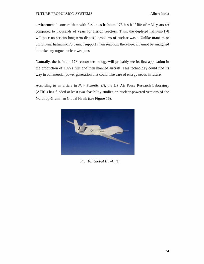
According to an article in New Scientist [7], the US Air Force Research Laboratory
(AFRL) has funded at least two feasibility studies on nuclear-powered versions of the
Northrop-Grumman Global Hawk (see Figure 16).
Fig. 16: Global Hawk. [8]
Page 24
FUTURE PROPULSION SYSTEMS Albert Jordà
25
3.4 Biomass Power
Biomass is organic material made from plants and animals. Biomass contains stored
energy from the sun. Plants absorb the sun's energy in a process called photosynthesis.
The chemical energy in plants gets passed on to animals and people that eat them.
Biomass can be used as a solid fuel, or converted into liquid or gaseous forms, for the
production of electric power, heat, chemicals, or fuels like biodiesel and ethanol. By
integrating a variety of biomass conversion processes, all of these products can be made
in one facility, called a biorefinery. Crops like corn and sugar cane can be fermented to
produce the transportation fuel, ethanol.
Production of ethanol fuel from the crops of corn grain is a well established technology.
The limiting factor is, of course, the feedstock itself – corn grain. It is an important food
and feed commodity. Producing too many litres of ethanol from the crops would cause
significant, unacceptable impacts on the economics of the other critical corn grain
products.
Ethanol from the cellulose promises to leap these ethanol capacity hurdles by utilizing
feedstocks which are abundant and do not compete with other needs. Cellulosic ethanol
(also called lignocellulosic ethanol) is a type of biofuel produced from lignocellulose, a
structural material that comprises much of the mass of plants. Lignocellulose is
composed mainly of cellulose, hemicellulose and lignin. Corn stover, switchgrass,
miscanthus and woodchip are some of the more popular cellulosic materials for ethanol
production. Cellulosic ethanol is chemically identical to ethanol from other sources,
such as corn starch or sugar, but has the advantage that the lignocellulose raw material
is highly abundant and diverse. But it differs in that it requires a greater amount of
processing to make the sugar monomers available to the microorganisms that are
typically used to produce ethanol by fermentation.
Advances in genetic engineering are making the fermentation of hemicellulose sugars
more productive as well. Improvements in such key technical areas will make
biochemical conversion of biomass to ethanol an efficient and economical route to
Page 25
FUTURE PROPULSION SYSTEMS Albert Jordà
26
alternative fuels production. However, the technology is relatively immature and there
are little more than a few pilot plants on the ground. For instance, at the National
Renewable Energy Laboratory (EUA), the biofuels focus is almost entirely on
advancing the cellulose ethanol technologies to enable competitively priced ethanol
from a variety of feedstocks.
It has already been proven that ethanol can work as an aviation fuel for piston engine
aircraft, some of them with 100% ethanol fuel like The Vanguard Squadron [9], which
is a formation aerobatic team. The companies are testing blended ethanol and other
synthetic fuels on the turbofan engines.
According to an article published in Airbus website [10], a test aircraft A380 MSN004
flew between Filton and Toulouse with one engine powered by alternative fuel. The
tests were run on an A380 as it is the most modern aircraft flying today, however the
fuel could equally have been tested on any Airbus aircraft.
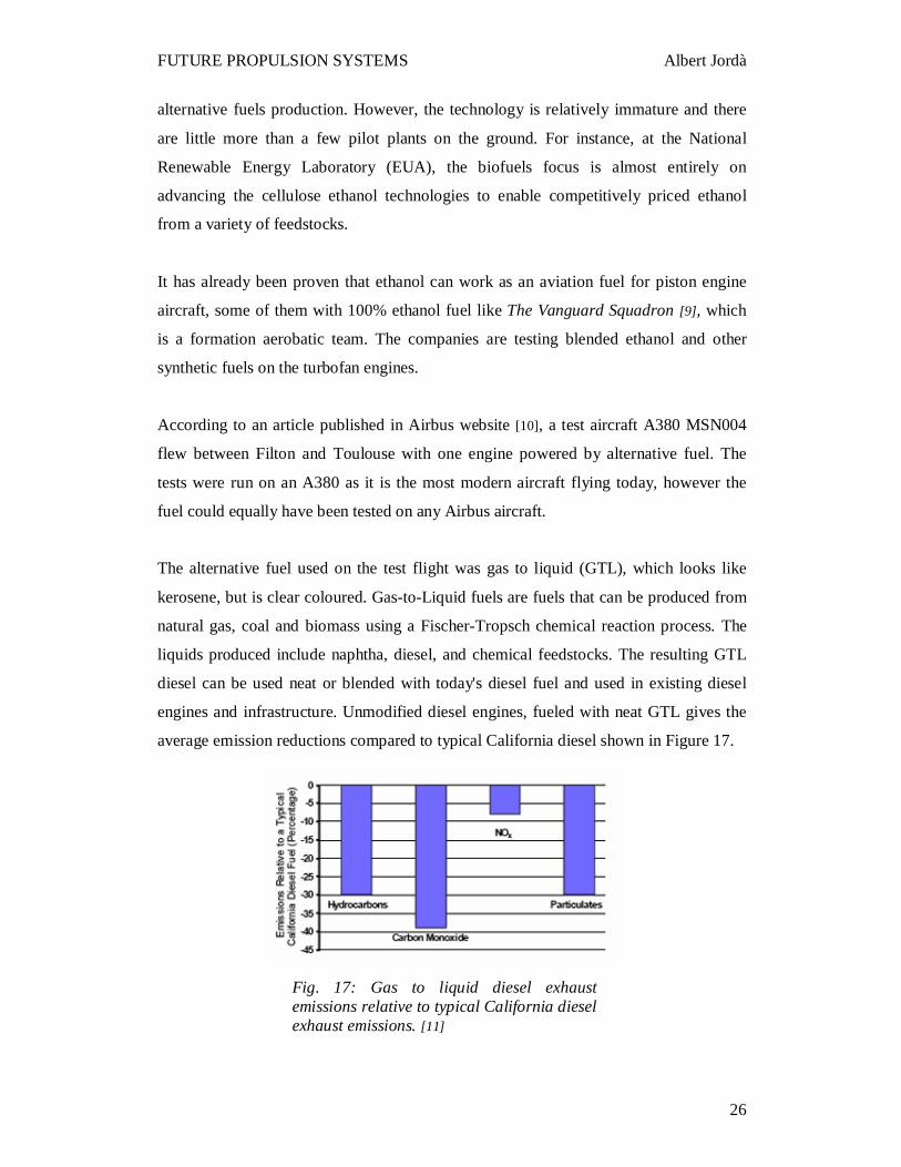
The alternative fuel used on the test flight was gas to liquid (GTL), which looks like
kerosene, but is clear coloured. Gas-to-Liquid fuels are fuels that can be produced from
natural gas, coal and biomass using a Fischer-Tropsch chemical reaction process. The
liquids produced include naphtha, diesel, and chemical feedstocks. The resulting GTL
diesel can be used neat or blended with today's diesel fuel and used in existing diesel
engines and infrastructure. Unmodified diesel engines, fueled with neat GTL gives the
average emission reductions compared to typical California diesel shown in Figure 17.
Fig. 17: Gas to liquid diesel exhaust emissions relative to typical California diesel exhaust emissions. [11]
Page 26
FUTURE PROPULSION SYSTEMS Albert Jordà
27
Oil and gas giant Shell supplied the GTL for the flight, saying on its website that for
transport, it is “a clear, clean fuel, virtually free of sulphur and aromatics and has a very
high combustion level”.
It also has “significantly lower emissions of local pollutants, such as particulates,
carbon monoxide, hydrocarbons and nitrogen oxides”, it said.
As synthetic fuels are reported to have similar characteristics, whatever their original
feedstock, this test was an excellent pre-cursor to research into biomass to liquid (BTL)
fuels, should a suitable supply become available.
A possible example of this sort of biomass to liquid fuel could have been used by Virgin
Atlantics during a demonstration flight the past February 2008. According to an article
published on their website [12], one of their Boeings 747 flew with no passengers on
board, using a truly sustainable type of biofuel that doesn’t compete with food and fresh
water resources.
Page 27
FUTURE PROPULSION SYSTEMS Albert Jordà
28
3.5 Battery/Fuel Cell Power
A fuel cell is an electrochemical device that converts hydrogen directly into electricity
and heat without combustion producing only water as a residual. Fuel cells are
emission-free and quieter than hydrocarbon fuel-powered engines. They save fuel and
are cleaner for the environment. Such devices can be used for primary or auxiliary
power generation in centralized or distributed electrical configurations.
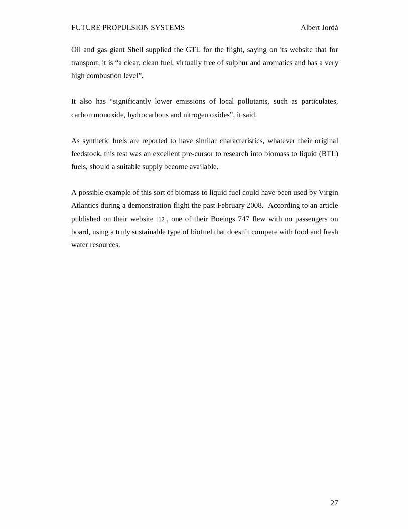
If the fuel cell is designed to operate also
in reverse as an electrolyser, then
electricity can be used to convert the water
back into hydrogen and oxygen (see
Figure 18). This dual-function system is
known as a reversible or unitized
regenerative fuel cell (URFC). Lighter
than a separate electrolyser and generator,
a URFC is an excellent energy source in
situations where weight is a concern.
As it is explained below, flight tests will
demonstrate for the first time that a
manned airplane can maintain a straight
level flight with fuel cells as the only power
source.
Fuel-cell powered manned intercity aircraft
are now being developed thanks to the solid
support of the EU. The project is called
ENFICA-FC, which means Environmentally Friendly Inter-City Aircraft powered by
Fuel-Cells. The overall budget is 4.9M€ of which 2.9M€ will be funded by the
European Commission [14]. This project, which is led by Politecnico di Torino and
comprising 11 partners and was launched on the 1st of October 2006, is helping
Europeans prove their prowess on the global stage.
Fig. 18: The electrochemistry of unitized regenerate fuel cell. In the fuel-cell mode, a proton-exchange membrane combines oxygen and hydrogen to create electricity and water. When the cell reverses operation to act as an electrolyser, electricity and water are combined to create oxygen and hydrogen. [13]
Page 28
FUTURE PROPULSION SYSTEMS Albert Jordà
29
The main objective of the ENFICA-FC project is to develop and validate the use of a
fuel cell based power system for the propulsion of more/all electric aircraft. The fuel
cell system will be installed in a selected aircraft which will be flight and performance
tested as a proof of functionality and future applicability for inter city aircraft. Through
this project, the research and industrial Consortium partners will focus on developing
and providing operational zero-pollution solutions to the immediate needs of aircraft
services.
According to Giulio Romeo, Full Professor of Airplane Design and Aerospace
Structures at Turin Polytechnic University, hydrogen and fuel cell power technologies
have now reached the point where they can be exploited to initiate a new era of
propulsion systems for light aircraft and small commuter aircraft. The primary
advantages of deploying these technologies are low noise and low emissions – features
which are particularly important for commuter airplanes that usually takeoff and land
from urban areas. The possibility to takeoff and land without contravening the noise
abatement regulations set for small airfields, in urban areas and near population centres,
will allow the use of these airfields during the late night hours when the noise abatement
regulations are even more stringent.
In addition, these technologies can also be developed for the future replacement of on-
board electrical systems in larger ‘more-electric’ or ‘all-electric’ aircraft. Systems that
could be powered by fuel cells might include Auxiliary Power Unit (APU), Primary
electrical generation supply, Emergency electrical power supply, Landing gear, De-
icing system, etc.
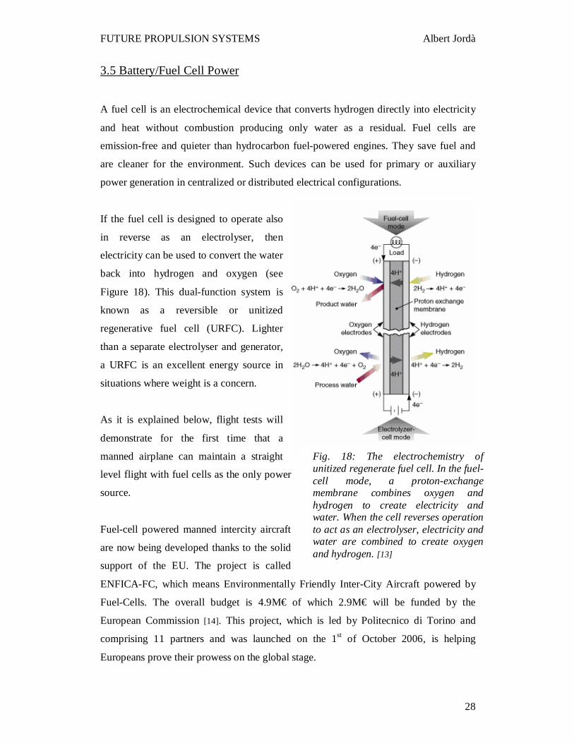
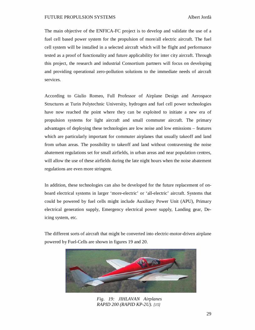
The different sorts of aircraft that might be converted into electric-motor-driven airplane
powered by Fuel-Cells are shown in figures 19 and 20.
Fig. 19: JIHLAVAN Airplanes RAPID 200 (RAPID KP-2U). [15]
Page 29
FUTURE PROPULSION SYSTEMS Albert Jordà
30
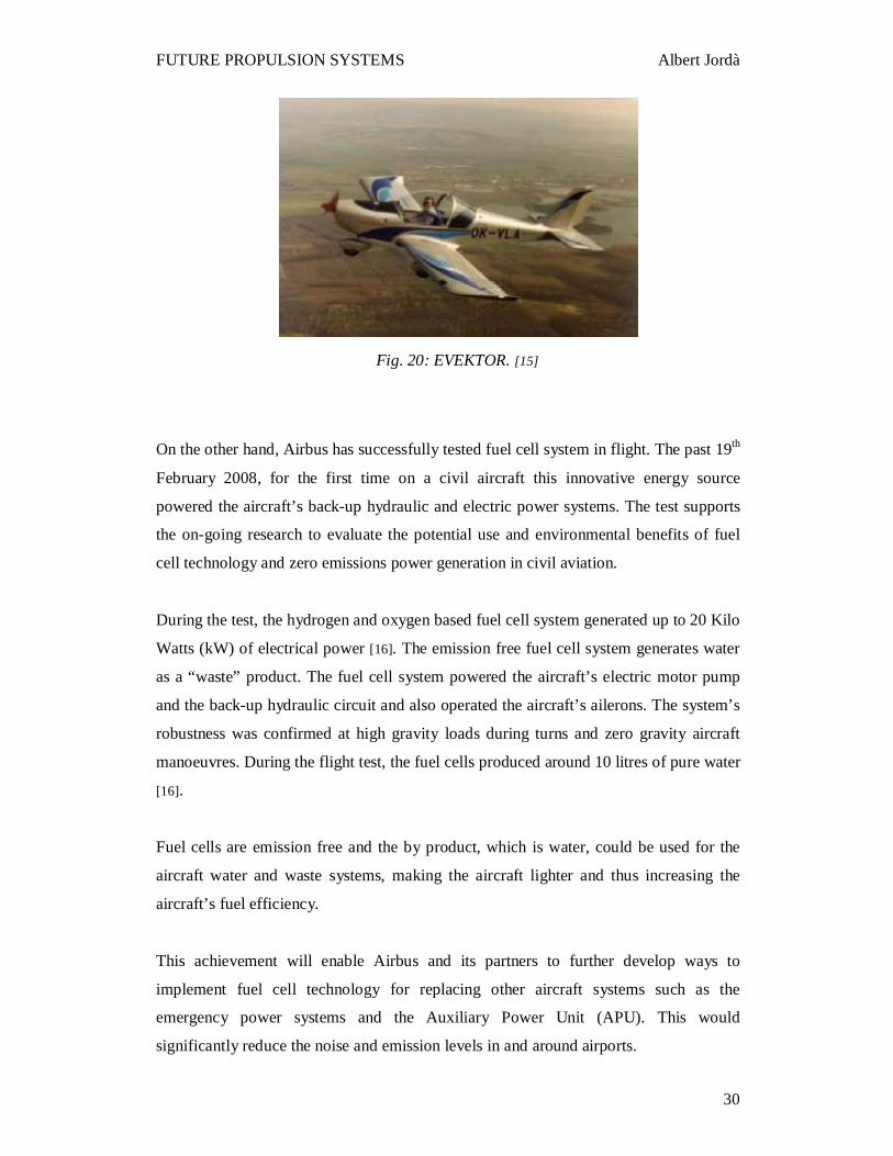
On the other hand, Airbus has successfully tested fuel cell system in flight. The past 19th
February 2008, for the first time on a civil aircraft this innovative energy source
powered the aircraft’s back-up hydraulic and electric power systems. The test supports
the on-going research to evaluate the potential use and environmental benefits of fuel
cell technology and zero emissions power generation in civil aviation.
During the test, the hydrogen and oxygen based fuel cell system generated up to 20 Kilo
Watts (kW) of electrical power [16]. The emission free fuel cell system generates water
as a “waste” product. The fuel cell system powered the aircraft’s electric motor pump
and the back-up hydraulic circuit and also operated the aircraft’s ailerons. The system’s
robustness was confirmed at high gravity loads during turns and zero gravity aircraft
manoeuvres. During the flight test, the fuel cells produced around 10 litres of pure water
[16].
Fuel cells are emission free and the by product, which is water, could be used for the
aircraft water and waste systems, making the aircraft lighter and thus increasing the
aircraft’s fuel efficiency.
This achievement will enable Airbus and its partners to further develop ways to
implement fuel cell technology for replacing other aircraft systems such as the
emergency power systems and the Auxiliary Power Unit (APU). This would
significantly reduce the noise and emission levels in and around airports.
Fig. 20: EVEKTOR. [15]
Page 30
FUTURE PROPULSION SYSTEMS Albert Jordà
31
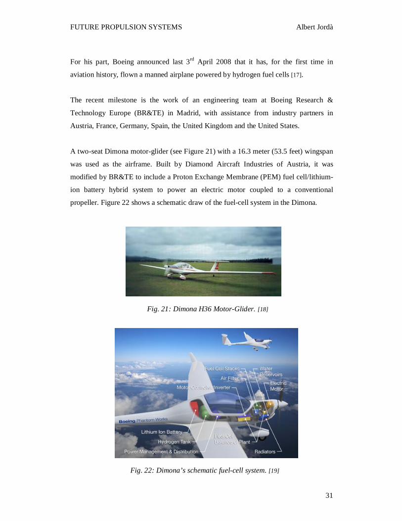
Fig. 21: Dimona H36 Motor-Glider. [18]
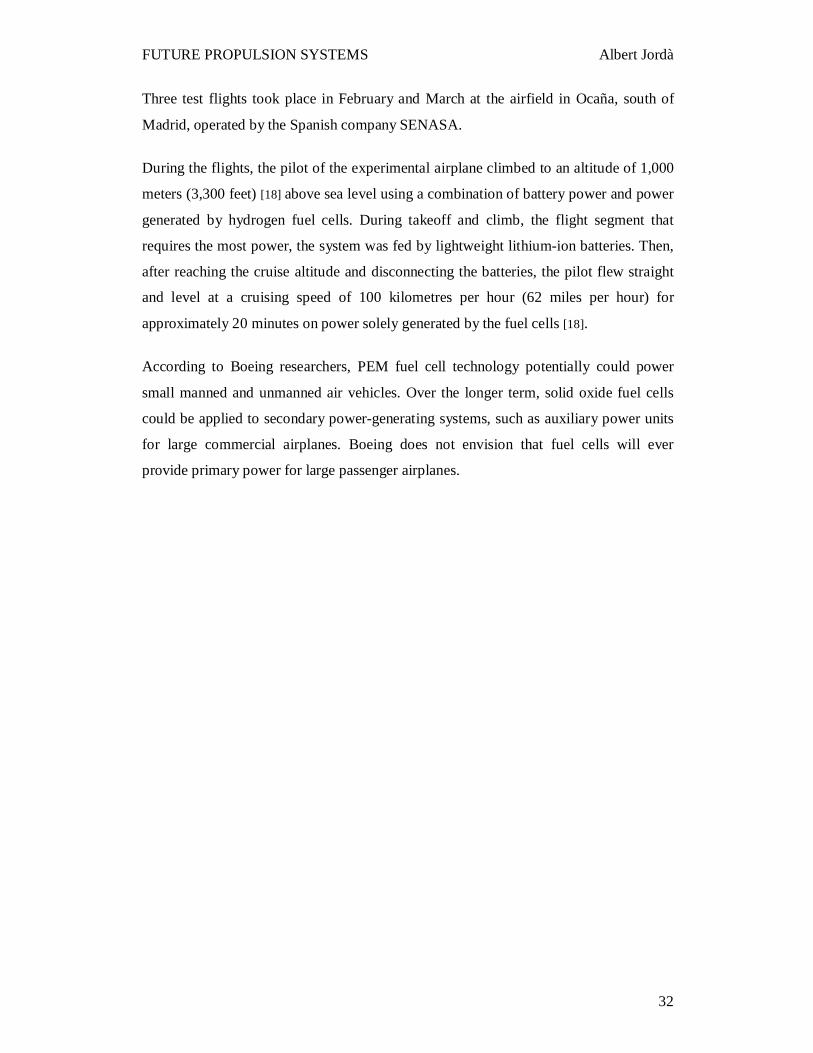
Fig. 22: Dimona’s schematic fuel-cell system. [19]
For his part, Boeing announced last 3rd April 2008 that it has, for the first time in
aviation history, flown a manned airplane powered by hydrogen fuel cells [17].
The recent milestone is the work of an engineering team at Boeing Research &
Technology Europe (BR&TE) in Madrid, with assistance from industry partners in
Austria, France, Germany, Spain, the United Kingdom and the United States.
A two-seat Dimona motor-glider (see Figure 21) with a 16.3 meter (53.5 feet) wingspan
was used as the airframe. Built by Diamond Aircraft Industries of Austria, it was
modified by BR&TE to include a Proton Exchange Membrane (PEM) fuel cell/lithium-
ion battery hybrid system to power an electric motor coupled to a conventional
propeller. Figure 22 shows a schematic draw of the fuel-cell system in the Dimona.
Page 31
FUTURE PROPULSION SYSTEMS Albert Jordà
32
Three test flights took place in February and March at the airfield in Ocaña, south of
Madrid, operated by the Spanish company SENASA.
During the flights, the pilot of the experimental airplane climbed to an altitude of 1,000
meters (3,300 feet) [18] above sea level using a combination of battery power and power
generated by hydrogen fuel cells. During takeoff and climb, the flight segment that
requires the most power, the system was fed by lightweight lithium-ion batteries. Then,
after reaching the cruise altitude and disconnecting the batteries, the pilot flew straight
and level at a cruising speed of 100 kilometres per hour (62 miles per hour) for
approximately 20 minutes on power solely generated by the fuel cells [18].
According to Boeing researchers, PEM fuel cell technology potentially could power
small manned and unmanned air vehicles. Over the longer term, solid oxide fuel cells
could be applied to secondary power-generating systems, such as auxiliary power units
for large commercial airplanes. Boeing does not envision that fuel cells will ever
provide primary power for large passenger airplanes.
Page 32
FUTURE PROPULSION SYSTEMS Albert Jordà
33
3.6 Hydrogen Power
Hydrogen fuel can be prepared by electrolysis of water (i.e. passing an electric current
through it) to dissociate it into its component parts of hydrogen and oxygen. When the
hydrogen fuel is burnt it combines with atmospheric oxygen to produce non-polluting
water vapour. If the electricity used to produce the hydrogen comes from alternative
sources such as wind, wave generators, solar panels, etc. then a closed and totally
environmentally friendly cycle can be created.
The physical and combustion properties of hydrogen give rise to hazards that must be
considered when designing and operating a hydrogen system. One of the major
concerns in the use of hydrogen is that of fire or detonation because of hydrogen’s wide
flammability range, low ignition energy, and flame speed. Other concerns include the
contact and interaction of hydrogen with materials, such as the hydrogen embrittlement
of materials and the formation of hydrogen hydrides. The low temperature of liquid and
slush hydrogen bring other concerns related to material compatibility and pressure
control; this is especially important when dissimilar, adjoining materials are involved.
The potential hazards arising from these properties and design features necessitate a
proper hydrogen hazards analysis before introducing a material, component, or system
into hydrogen service. The next three points describe and classify the main hydrogen
hazards:
3.6.1 Combustion Hazard
Hydrogen is flammable. Therefore, fire is a primary hydrogen hazard to consider. A fire
can result from the following scenarios.
• Hydrogen is released, mixes with an oxidizer, and forms a combustible mixture. The
mixture contacts an ignition source and ignition occurs.
• The hydrogen system is contaminated with an oxidizer as a result of improper purging
and/or in leakage of an oxidizer, such as air. The hydrogen and the oxidizer form a
combustible mixture, the combustible mixture contacts an ignition source, and ignition
occurs.
Page 33
FUTURE PROPULSION SYSTEMS Albert Jordà
34
• Hydrogen or an oxidizer leak from one part of a system into another part of the system
where a combustible mixture is formed and ignited.
3.6.2 Pressure Hazard
Hydrogen has a significant expansion ratio in its conversion from a liquid at normal
boiling point to a gas at normal temperature and pressure; therefore, overpressure is
another hydrogen hazard to be considered. Overpressure can result in:
• Excessive deformation and subsequent release of hydrogen.
• Rupture of the pressure vessel, which would release hydrogen (this could provide the
ignition source) and/or produce projectiles from vessel fragments.
Gaseous hydrogen is compressible, and a compressed gas can have a significant
potential energy. Therefore, this is another pressure hazard to be considered.
3.6.3 Hydrogen-Related Injuries
Potential hydrogen-related accidents and injuries are described below.
Asphyxiation: Asphyxiation can result if hydrogen or inert gases used for purging a
hydrogen system displace the oxygen in a breathing atmosphere.
Blast Overpressure: Blast overpressure can result from a detonation or from the
unconfined expansion of a compressed gas.
Burn: A burn can result from direct contact with a hydrogen fire, thermal radiation from
a hydrogen fire, or contact with a surface that has been heated by a hydrogen fire.
Fragments: An explosion can produce fragments from the container of an explosive
mixture or from structures or other items near the explosion. These fragments can result
in injury or death to personnel, and damage or destruction of equipment.
Frostbite (Freezing, Cryogenic Burn). Frostbite can result from contact with a cold fluid
or a cold surface.
Hypothermia: Hypothermia can occur if the body temperature is lowered as a
consequence of a cold environment, such as from a liquid hydrogen spill.
Page 34
FUTURE PROPULSION SYSTEMS Albert Jordà
35
Most hydrogen systems isolate personnel from direct exposure to hydrogen. For
example, we mitigate frostbite danger from liquid hydrogen by using personal
protective equipment and with proper equipment insulation and barriers.
There are a number of modifications required to current aircraft engines and aircraft
structures before hydrogen fuel can be used. Hydrogen contains approximately three
times as much energy per kilogram as kerosene which means that only a third as much
fuel by weight needs to be carried to cover a certain range. However, hydrogen is a
significantly less dense fuel than kerosene and will need much larger aircraft fuel tanks
even when the fuel is stored in liquid form at -253 °C [3] as it will have to be. Even
taking into account the fact that only one third of the weight of hydrogen will be
required, fuel tanks on a hydrogen powered aircraft will need to be 4 times [3] the
volume of those on conventional aircraft. These tanks will have to be heavily insulated
because of the low storage temperature and spherical or cylindrical tanks placed above
the main passenger compartments are the best option. The fuselage of aircraft will
become stockier to accommodate this change.
Only small modifications will be needed to enable aircraft engines to burn hydrogen but
specialised fuel pumps, pipes, control valves and refuelling systems will be needed in a
hydrogen powered engine.
As the hydrogen fuel will be mixed with air (specifically the oxygen contained in air)
and then ignited in the engines some nitrogen oxides (NOx) emissions will result from
the combustion process since nitrogen is the major component of air. However, NOx
emissions from hydrogen fuelled engines can be lowered by up to 80%, as compared
with kerosene burning engines, using a process called Micromix developed by the
University of Aachen. The large amounts of water vapour produced by hydrogen
engines could also be a problem as water vapour acts as a greenhouse gas but only at
altitudes above 10 Km. Restricting the altitude at which planes fly could solve this
problem.
The usage of hydrogen was tested in the past by means of a program called Cryoplane,
which started on the 1st of April 2000. However, this program was stopped in the face of
enormous investment and operating costs and the still existing emissions of NOx.
Page 35
FUTURE PROPULSION SYSTEMS Albert Jordà
36
Another programme related with hydrogen is the European Commission funded
LAPCAT (Long-term Advanced Propulsion Concepts and Technologies), which is
focusing on advanced hypersonic propulsion concepts for long-distance and suborbital
air transport. The project coordinated by the European Space Agency (ESA) and under
the 6th Framework programme promises faster and easier access to all world
destinations.
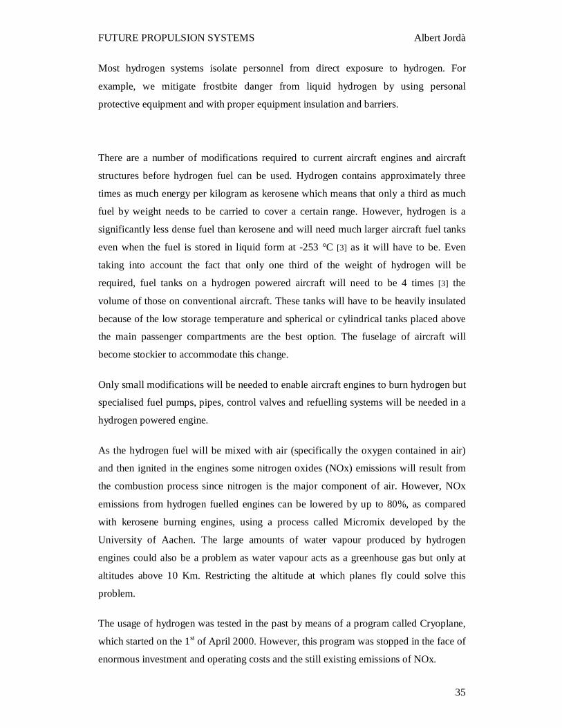
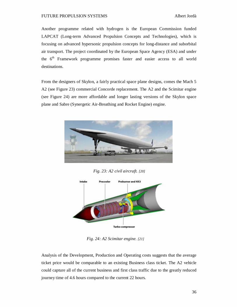
From the designers of Skylon, a fairly practical space plane designs, comes the Mach 5
A2 (see Figure 23) commercial Concorde replacement. The A2 and the Scimitar engine
(see Figure 24) are more affordable and longer lasting versions of the Skylon space
plane and Sabre (Synergetic Air-Breathing and Rocket Engine) engine.
Analysis of the Development, Production and Operating costs suggests that the average
ticket price would be comparable to an existing Business class ticket. The A2 vehicle
could capture all of the current business and first class traffic due to the greatly reduced
journey time of 4.6 hours compared to the current 22 hours.
Fig. 24: A2 Scimitar engine. [21]
Fig. 23: A2 civil aircraft. [20]
Page 36
FUTURE PROPULSION SYSTEMS Albert Jordà
37
Unlike Concorde the A2 vehicle has exceptional range (approx 20000 km both subsonic
and supersonic) and is therefore able to service a large number of routes whilst
simultaneously avoiding supersonic over flight of populated areas. Its good subsonic
performance enables it to service conventional subsonic overland routes thereby
increasing its sales potential to airlines.
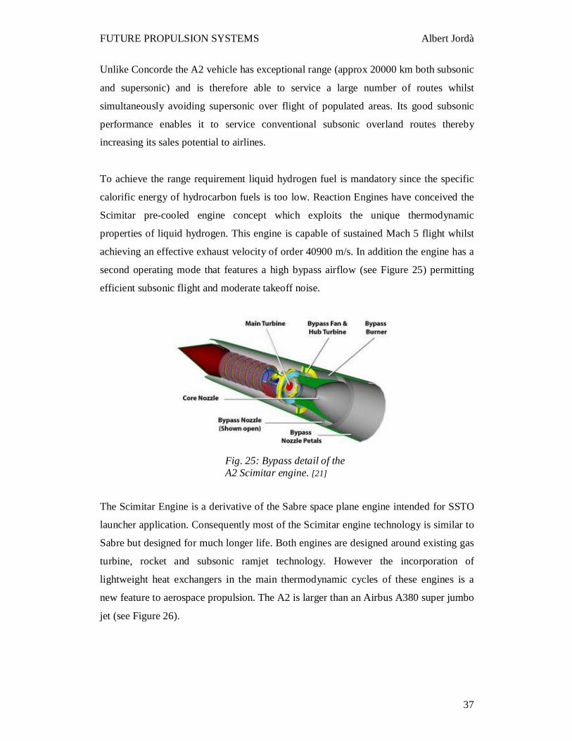
To achieve the range requirement liquid hydrogen fuel is mandatory since the specific
calorific energy of hydrocarbon fuels is too low. Reaction Engines have conceived the
Scimitar pre-cooled engine concept which exploits the unique thermodynamic
properties of liquid hydrogen. This engine is capable of sustained Mach 5 flight whilst
achieving an effective exhaust velocity of order 40900 m/s. In addition the engine has a
second operating mode that features a high bypass airflow (see Figure 25) permitting
efficient subsonic flight and moderate takeoff noise.
The Scimitar Engine is a derivative of the Sabre space plane engine intended for SSTO
launcher application. Consequently most of the Scimitar engine technology is similar to
Sabre but designed for much longer life. Both engines are designed around existing gas
turbine, rocket and subsonic ramjet technology. However the incorporation of
lightweight heat exchangers in the main thermodynamic cycles of these engines is a
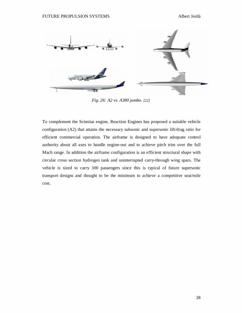
new feature to aerospace propulsion. The A2 is larger than an Airbus A380 super jumbo
jet (see Figure 26).
Fig. 25: Bypass detail of the A2 Scimitar engine. [21]
Page 37
FUTURE PROPULSION SYSTEMS Albert Jordà
38
To complement the Scimitar engine, Reaction Engines has proposed a suitable vehicle
configuration (A2) that attains the necessary subsonic and supersonic lift/drag ratio for
efficient commercial operation. The airframe is designed to have adequate control
authority about all axes to handle engine-out and to achieve pitch trim over the full
Mach range. In addition the airframe configuration is an efficient structural shape with
circular cross section hydrogen tank and uninterrupted carry-through wing spars. The
vehicle is sized to carry 300 passengers since this is typical of future supersonic
transport designs and thought to be the minimum to achieve a competitive seat/mile
cost.
Fig. 26: A2 vs. A380 jumbo. [22]
Page 38
FUTURE PROPULSION SYSTEMS Albert Jordà
39
4. RESULTS AND DISCUSSION
In this section a comparison among the further systems already presented in sections
3.2, 3.3, 3.4, 3.5 and 3.6 will be made. To start with, a summary of the main features
will be exposed stressing the importance of the advantages and disadvantages for each
one of them. After that, a discussion and evaluation of these results will bring us to the
final conclusions.
4.1 Solar Power
4.1.1 Advantages
• Totally renewable energy source.
• Applicable to commercial aircraft which may fly at high altitudes carrying low
payloads.
• There is not a lot of necessary investment to assemble solar panels on the
aircraft that may need them.
4.1.2 Disadvantages
• Solar panels provide too low efficiency to become a propulsion system.
• The flight performance is limited by the conditions of the sun rays.
4.2 Nuclear Power
4.2.1 Advantages
• Using hafnium-178 triggered by X-rays the energy output to input ratio is 60.
• The hafnium fuelled reactor produces gamma radiation only and no neutrons,
therefore, less thick shielding is required than the required for a fission reactor.
• As no destructive cascade energy is released, the power generation can be tightly
controlled.
• In case an accident occurs, there is less environmental concern than with fission.
Page 39
FUTURE PROPULSION SYSTEMS Albert Jordà
40
• Hafnium-178 cannot support chain reaction, therefore, it cannot be smuggled to
make any rogue nuclear weapons.
4.2.2 Disadvantages
• A shielding to protect the crew is still required; therefore fewer payloads could
be carried.
• A large number of modifications are required to the current aircraft
configuration and infrastructures as well as economical investment.
• Radioactive waste would still exist, and therefore, a place to put the nuclear
residual would be also required.
4.3 Biomass Power
4.3.1 Advantages
• Burning biofuels results in an important reduction of the polluting fumes
emissions.
• There is not a lot of required investment to make fuel from the biomass.
Investment is only required to create new plants and develop the biofuel from
cellulose.
4.3.2 Disadvantages
• Using or producing biofuels at large scale may cause a negative impact on the
environment and the price of several foods.
• Biofuels are usually more expensive.
Page 40
FUTURE PROPULSION SYSTEMS Albert Jordà
41
4.4 Battery/Fuel Cell Power
4.4.1 Advantages
• Fuel cells convert hydrogen into electricity without combustion producing water
as a residual.
• Fuel cells are emission-free.
• Fuel cells are quieter than hydrocarbon fuel-powered engines.
• Fuel cells can operate also in reverse as an electrolyser, and then electricity can
be used to convert the water back into hydrogen and oxygen.
• Fuel cells can supply enough energy to propel intercity aircraft.
• There is not a big investment to make since fuel cells have already been tested
successfully as a source of electricity for auxiliary power units and as a source of
propulsion for intercity aircraft.
4.4.2 Disadvantages
• Fuel cells can not supply enough energy to propel large scale aircraft.
• All the potential hazards derived from the hydrogen use must be considered.
4.5 Hydrogen Engines Power
4.5.1 Advantages
• Hydrogen production can be based upon every renewable energy used to
produce electricity.
• Hydrogen can be produced by electrolysis of water - basically everywhere.
• Burning hydrogen produces water and therefore, the cycle is closed.
• Hydrogen offers high energy content per mass, hence promises payload or range
increase for aircraft.
• Scimitar engines give the possibility of perform at hypersonic speeds.
Page 41
FUTURE PROPULSION SYSTEMS Albert Jordà
42
4.5.2 Disadvantages
• For aviation, hydrogen must be cooled down to the liquid state (LH2, -253°C)
for reasons of volume and weight of tanks.
• LH2 needs:
- Approximately 4 times greater volume than kerosene.
- Very good insulation of tanks, pipes and other parts.
- Tanks under some differential pressure.
- Spherical or cylindrical tanks.
- New aircraft configuration.
• All the potential hazards derived from the hydrogen use must be considered.
• There is still a big investment to do to develop the hydrogen combustion
engines, to make and assembly them into all aircraft and to change aircraft
airframe and structures.
Page 42
FUTURE PROPULSION SYSTEMS Albert Jordà
43
4.6 Discussion
In this section, the information exposed in the chapter Review of Literature and the
consequent list of advantages and disadvantages listed above will be used as a basis to
compare the different systems’ features and discuss what could happen in the next years
about the propulsion systems.
Note that all the predictions presented will be based on not much specific information.
Because of the current relevance of the subject dealt with in this project, the desirable
specific information is very restricted by the research departments and companies. If
such information were available a more analytical comparison could be done, using
statistics, data and values. In spite of the unavailability of specific information, a
parallel analysis will be done without numerical data.
To start with, the possible solutions that have already been described could be classified
as short and long term changes. This classification would be according to parameters
such as the requirement of economic investment, infrastructure changes, airframe
changes, more research and development, new products or fuels, etc.
Firstly, solar power could be part of the short period changes group. Because of the low
energy level supplied from such a system, it could be only useful for very light planes,
as explained in the examples of section 3.2. The other obvious problem is the
impossibility of using solar power during the night or when there are inappropriate sun
rays conditions. Planes like Helios are able to fly at high altitudes carrying light
payloads. Therefore, the utility of this propulsion system is restricted to government or
commercial applications such as surveillance, investigation, communications, etc.
It is identified as a short term solution because it is easy to assemble solar panels to
provide electric energy either it is to be used as a source of propulsion or a source of
energy for any other system in larger planes. Furthermore, there is not a big investment
required to develop or research on current solar panels for aircraft, because it has
already been demonstrated in flight tests how they work and what can be expected from
Page 43
FUTURE PROPULSION SYSTEMS Albert Jordà
44
them. The only structural change required would be to assemble useful solar panels on
the wings of all large scale planes.
However, solar power could be part of the long term changes group as well. In a
program called High Altitude Airships developed by Lockheed Martin, solar panels
would cover the airship skin and the combination of photovoltaic and advanced energy
storage systems would deliver the necessary power to perform the airship functions.
Currently solar panels are made from silicon, which makes them expensive to
manufacture and therefore cost prohibitive for many. However, new technology being
researched at Cambridge University uses plastic to create solar cells which is a much
more cost effective and energy efficient method [23]. Taking this into account,
expectations on solar power could be of interest again. Manned airships could be made
to fly at transport altitudes for human move (instead of High Altitude Airships), also
propelled using solar power from the cells.
Secondly, the power from the biofuels is another system that could be included in the
short term changes group. As shown in Figure 17, the use of biofuels would result in a
reduction of the noxious fumes emissions to the atmosphere. However, there are very
important factors to take in consideration: the ecological sustainability and the economy
related with the other derivative products from the same feedstock as the biofuel. On the
one hand, the consequences derived from planting huge fields of crops destined to the
biofuel production could be very negative in regards to the natural biological cycle and
even more if woods deforesting is involved to create new fields. This cycle would not
be closed if biofuels are burned, process that would cause unsustainability. On the other
hand, the prices of the rest of the derivative products from the crops would be more
expensive because of the supply – demand law. Actually, this problem is already
happening. There have been several demonstrations (i.e. Egypt or Haiti) in which the
main issue was the increase of food prices.
“The United States and the European Union have taken a criminal path by contributing
to an explosive rise in global food prices through using food crops to produce biofuels,
the United Nations Special Rapporteur on the right to food said on the 28th April 2008.
At a press conference in Geneva, Jean Ziegler of Switzerland said that fuel policies
Page 44
FUTURE PROPULSION SYSTEMS Albert Jordà
45
pursued by the U.S. and the EU were one of the main causes of the current worldwide
food crisis. Ziegler said that last year the United States used a third of its corn crop to
create biofuels, while the European Union is planning to have 10 percent of its petrol
supplied by biofuels” [24].
Therefore, biofuels should be used as a part of the whole energy sources to propel
aircrafts, or even they could act helpfully as transition fuels until a better solution was
achieved. Note that the technology to make biofuels is very developed, even though
more research and development is being carried out. Because of this and the fact that
there is not a lot of investment to do, biofuels are not very short term solutions, they are
even a current application. As explained in section 3.4, the most important companies
are using biofuels to improve the efficiencies of their engines and to reduce noxious
fumes emissions. If the biofuel used by Virgin Atlantics actually does not compete with
food or water products, it should be considered by the rest of industries in the world to
achieve and use the same biofuel. It is in the interest of society in general to avoid
economic problems, food crisis or democratic conflicts.
Another system proposed in this project is battery/fuel cells. As explained in section
3.5, they may supply enough energy to propel intercity aircraft. In the future all the
intercity aircraft could be propelled from the fuel cell systems’ energy. This would also
result in a reduction of the noxious fumes emissions for that sort of aircraft. For large
scale aircraft, fuel cells can not supply enough energy to act as the propulsion system,
so they may be used as the energy source for other electric systems such as the auxiliary
power unit, aircraft control systems, air conditioner, etc. This would result in increasing
the fuel efficiency, reducing the fossil fuel consumption and a reduction of the noxious
fumes emission as well (emissions from the actual propulsion system that would be
working).
On the other hand, hydrogen and nuclear power engines would be part of the long term
changes group. Such systems require more research, tests, investment, airframe changes
and infrastructural changes, and involve serious potential hazards, especially nuclear
power. Although the potential interest that they have, the projects to develop them are
very expensive. This reason might cause the stoppage of such projects, as happened
with the Cryoplane or with the nuclear research programmes after World War II.
Page 45
FUTURE PROPULSION SYSTEMS Albert Jordà
46
Hydrogen presents very attractive advantages. It is easy to obtain by electrolysis of
water and the energy level per unit of mass contained, and able to be supplied, is high
enough to propel large scale aircraft for a very long range. It also promises the
capability of carrying high payloads and even flying at hypersonic velocity. The engines
would not need drastic changes to be adapted for hydrogen combustion.
However, the potential hazards arising from hydrogen must be taken into account. This
is one of the facts that make the development of this system more expensive, as well as
the structural changes required. The potential hazards imply the need for research and
strong feasibility and liability studies, as well as the requirement of using new
technologies or system parts. The structural changes required would include changes in
the factories, where the engines and the aircraft are made, and also the airports in the
case that the new airframes require new infrastructures (hangars, ways, parking, etc).
The still remaining NOx emissions, as explained in section 3.6, could be reduced using
the Micromix process or even solved with further studies. The large production of steam
should not be a problem for the greenhouse effect if the flying altitude is restricted.
With the discovery of hafnium-178 and the corresponding X-Ray triggering, nuclear
power recovers the potential interest to propel aircraft in the future. The electric energy
required to run the X-Ray source could be supplied from solar panels or fuel cells, and
the energy output would be high enough propel large scale aircraft. However, nuclear
energy would be the last resource to take into account to propel aircraft in the long term
future due to the negative issues listed below:
• Only feasibility studies have been carried, no actual flying tests (according to the
information published).
• Nuclear energy involves even more hazards than hydrogen gas.
• A heavy shield is still required to isolate the nuclear core.
• Radioactive waste would still remain after its use.
• Airframe and structural changes are required.
Page 46
FUTURE PROPULSION SYSTEMS Albert Jordà
47
According to all the comparisons done, the propulsion system in the near future could
be a mix of the cheaper, feasible and sustainable solutions. For instance, it could be
really interesting to reduce the noxious gas emissions substituting the current engines by
implementing fuel cells to supply the electric energy required with the help of solar
panels, changing all the intercity aircraft engines to fuel cell energy systems and burn
biofuels while keeping researching and developing the hydrogen engines. Airships
could be made again, switching the propulsion energy from solar energy during the day
to biofuels or battery/fuel cells during the night.
It is obvious that it is not possible to stop the fossil fuel consumption suddenly. The
same scenario acts in the world of aviation, where the oil derivative fuels can not be
radically wiped out at the moment. A continuous and slow process is required in order
to assimilate all the changes economically. The biofuels could be burned avoiding the
economic and ecologic problems if the making process of the new biofuel from the
cellulose is properly achieved.
Finally, the best long term solution to propel large scale aircraft would be hydrogen
power. The potential hazards involved are less worrying than nuclear energy, as well as
the pollution or natural concerns. If hydrogen engines are totally developed and applied,
fossil fuels will not be combusted any more in aircraft engines and probably society
would be able to travel at hypersonic speeds.
Page 47
FUTURE PROPULSION SYSTEMS Albert Jordà
48
5. CONCLUSIONS
The current trends showed by the most important aircraft engine manufacturers
(General Electric, Rolls Royce, Pratt & Whitney) are improvements in the engine
overall efficiency, reduction of specific fuel consumption and also of noxious gases
emissions.
They try to achieve these goals without changing to new propulsion systems. They try
to keep the same engines with mechanical and physical innovations that make them
more efficient. They are also testing and actually flying with engines that burn blended
oil derivative fuels with other composites or any sorts of synthetic fuels. Gas to liquid
and biomass derivative fuels are also being used. Pure biomass derivative fuels perform
properly in piston engines and have already been tested successfully in large scale
aircraft engines.
The alternatives to the current propulsion systems are solar power, nuclear power,
biomass power, battery/fuel cell power and hydrogen power. The applications of these
systems may be classified in short and long term innovations.
Up to now, solar cells have been expensive to make and they supply low energy level.
Therefore they could be used to propel very light aircraft or to supply extra energy for
the aircraft propelled using other systems. In this sense solar energy would be in the
short period group. However, futuristic projects for propelling High Altitude Airships
covered with solar cells would account for a long term solution. The interesting
discovers at Cambridge to make solar cells in a cheaper way must be taken into account.
Battery/fuel cells could propel all intercity aircraft and supply the electricity for systems
such as Auxiliary Power Unit among others in large scale aircraft in a short term period
of time. Using a mix of solar energy and fuel cells with the combination of biofuels
could be a good way to keep propelling aircraft in the short term future, helping the
aviation to become every day less oil derivative fuel dependent and decreasing the
noxious fumes emissions.
Page 48
FUTURE PROPULSION SYSTEMS Albert Jordà
49
Propulsion systems from the nuclear power and hydrogen power still require important
research and development projects, as well as large economic investments. Both
possible systems would offer huge energy output, promising range and big payloads,
but also involve serious potential hazards, especially nuclear power.
Fewer changes would be required to the current engines and airframes by switching to
hydrogen energy. Current futuristic projects which are developing hydrogen engines
promise hypersonic velocity for aircraft passenger flights. Therefore, there are more
probabilities of considering hydrogen, rather than nuclear power, the long term future
alternative fuel, bringing aviation to become totally oil independent.
Page 49
FUTURE PROPULSION SYSTEMS Albert Jordà
50
6. RECOMMENDATIONS
For further work, it would be highly recommendable to pay attention to the trends
followed by the main and giant aircraft companies in regard to the aircraft turbines and
propulsion. Their Research & Development sections have the tools to assess what are
the best steps to take. According to the overall expenses that the companies generate,
they may be able to evaluate whether is it necessary or no to invest on new systems and
technologies such the ones presented in this project, or is better to improve the current
systems and their efficiencies.
Other important organizations like European Commission can act as a key factor
funding part of the research programmes proposed by other partners. Therefore, it is
also of interest to pair attention to the trends given by the European Commission
research programmes, like the 6th Framework.
It is sure that further research on the problem dealt with in this project must keep active.
Continuing the study of the future propulsion systems might be easier using those
sources of information and the characteristics of the systems available that could replace
the current oil-dependent engines.
Page 50
FUTURE PROPULSION SYSTEMS Albert Jordà
51
7. REFERENCES
1. Too little oil being found to maintain production. Past discovery based on
ExxonMobil (2002).
http://info.energyscenariosireland.com/The_Growing_Gap
Electronically accessed October, 2007.
2. Green Car Congress.
http://www.greencarcongress.com/2004/12/indiarsquos_oil.html
Electronically accessed November, 2007.
3. Dr. Reinhard Faab (2001). Cryoplane. Airbus Deutschland.
http://www.fzt.haw-hamburg.de/pers/Scholz/dglr/hh/text_2001_12_06_Cryoplane.pdf
Electronically accessed December, 2007.
4. Joyce E. Penner; David H. Lister; David J. Griggs; David J. Dokken; Mack
McFarland. Intergovernamental Panel on Climate Change. Aviation and the Global
Athmosphere.
http://www.grida.no/climate/ipcc/aviation/
Electronically accessed December, 2007.
5. Pratt & Whitney (March 2008); Pratt & Whitney Installs Geared Turbofan™ Engine
Flight Nacelle System, Prepares for Phase II Testing.
http://www.pw.utc.com/vgn-ext-templating/v/index.jsp?vgnextoid=fa937b48ad2cb010
VgnVCM1000000881000aRCRD
Electronically accessed March, 2008.
5a. Hill, R.J. (1996). The purpose and status of IHPTET-1995. In: Advanced Aero-
Engine Concepts and Controls. Advisory Group for Aerospace Research and
Development.
6. Solar-Power Research.
http://www.nasa.gov/centers/dryden/news/FactSheets/FS-054-DFRC.html
Page 51
FUTURE PROPULSION SYSTEMS Albert Jordà
52
Electronically accessed November, 2007.
7. Duncan Graham-Rowe (2003). Nuclear-powered drone aircraft on drawing board.
http://environment.newscientist.com/article/dn3406
Electronically accessed March, 2008.
8. RQ-4A/B Global Hawk High-Altitude, Long-Endurance, Unmanned Reconnaissance
Aircraft, USA.
http://www.airforce-technology.com/projects/global/images/4_global_hawk.jpg
Electronically accessed March, 2008.
9. Vanguard Squadron.
http://www.ethanolairshows.com/
Electronically accessed January, 2008.
10. Airbus (February 2008). A380 flies on alternative fuel.
http://www.airbus.com/en/corporate/ethics/environment/eco-efficiency/
Electronically accessed March, 2008.
11. February 2006. Gas-to-Liquid Fuels in Transportation.
http://www.energy.ca.gov/afvs/vehicle_fact_sheets/gtl.html
Electronically accessed April, 2008.
12. Virgin Atlantic (January 2008). Virgin Atlantic to run 747 on Biofuel in February.
http://www.virgin.com/News/Articles/VirginAtlantic/2008/140108.aspx
Electronically accessed February, 2008.
13. Katie Walter. The Unitized Regenerative Fuel-Cell.
http://ec.europa.eu/research/headlines/news/article_07_06_27_en.html
Electronically accessed 1 December, 2007.
14. European Commission (June 2007). Fuel-Cell Powered Aircraft take to the skies.
http://ec.europa.eu/research/headlines/news/article_07_06_27_en.html
Electronically accessed January, 2008.
Page 52
FUTURE PROPULSION SYSTEMS Albert Jordà
53
15. ENFICA-FC (November 2007). Environmentally Friendly Inter City Aircraft
powered by Fuel-Cell.
http://www.enfica-fc.polito.it/en
Electronically accessed January, 2008.
16. Airbus (February 2008). Emission free power for civil aircraft: Airbus successfully
demonstrates fuel cells in flight.
http://www.airbus.com/en/presscentre/pressreleases/pressreleases_items/08_02_19_em
ission_free_power.html
Electronically accessed March, 2008.
17. Boeing (April 2008). Boeing Successfully Flies Fuel Cell-Powered Airplane.
http://www.boeing.com/news/releases/2008/q2/080403a_nr.html
Electronically accessed April, 2008.
18. Dimona H-36 Notes.
http://www.byrongliding.com/dimona_h36.htm
Electronically accessed February, 2008.
19. Boeing (March 2007). Boeing Prepares Fuel Cell Demonstrator.
http://www.boeing.com/phantom/news/2007/q1/070327e_nr.html
Electronically accessed April, 2008.
20. European Commission (February 2006). Commission funds hypersonic flight
project.
http://ec.europa.eu/comm/space/news/article_3846_en.html
Electronically accessed January, 2008.
21. Reaction Engines Limited- Space Propulsion Systems. LAPCAT - Scimitar Engine.
http://www.reactionengines.co.uk/lapcat_scim.html
Electronically accessed March, 2008.
Page 53
FUTURE PROPULSION SYSTEMS Albert Jordà
54
22. Reaction Engines Limited- Space Propulsion Systems. Image Library - LAPCAT.
http://www.reactionengines.co.uk/images_lapcat.html
Electronically accessed March, 2008.
23. University of Cambridge (October 2007). Affordable solar power on the horizon.
http://www.admin.cam.ac.uk/news/dp/2007100501
Electronically accessed April, 2008.
24. Environment News Service (April 2008). UN: Biofuel Production 'Criminal Path' to
Global Food Crisis.
http://www.ens-newswire.com/ens/apr2008/2008-04-28-03.asp
Electronically accessed April, 2008.