31
i | Page Fuzz Distortion Guitar Stompbox By James Cleary Senior Project Report Electrical Engineering Department California Polytechnic State University San Luis Obispo June 2020
i | P a g e
Fuzz Distortion Guitar Stompbox
By
James Cleary
Senior Project Report
Electrical Engineering Department
California Polytechnic State University
San Luis Obispo
June 2020

ii | P a g e
Table of Contents:
Chapter 1: Introduction ……………………………………………………. : Page 2
Chapter 2: Customer Needs, Requirements and Specifications …………... : Page 3
Chapter 3: Project Functional Decomposition …………………………….. : Page 7
Chapter 4: Project Planning ……………………………………………….. : Page 8
References …………………………………………………………………. : Page 9
Appendix A: Senior Project Analysis ………………………………...….. : Page 10
List of Tables:
Table I: Fuzz Distortion Specifications and Marketing Requirements ..… : Page 4
Table II: Fuzz Distortion Deliverables Due Dates …………………….... : Page 6
Table III: Fuzz Distortion Level 0 Function Table ……………………… : Page 8
Table IV: Gain Stage Function Table …………………………………… : Page 10
Table V: Minimum and Maximum Gain Values …………………………: Page 13
Table VI: Tone Stack Function Table …………………………………… : Page 14
Table VII: Output Stage Function Table ……………………………….... : Page 17
Table VIII: Power Supply Function Table ………………………….....… : Page 18
Table IX: Fuzz Distortion Projected Cost ……………………………..… : Page 21
List of Figures:
Figure 1: Fuzz Distortion Level 0 Block Diagram …………………..….. : Page 8
Figure 2: Fuzz Distortion Full Schematic ………………………………... : Page 8
Figure 3: Fuzz Distortion Level 1 Block Diagram …………………...….. : Page 10
Figure 4: Fuzz Distortion Gain Stage Schematic ………………………... : Page 12
Figure 5: Tone Stack Design Schematic ………………………………… : Page 15
iii | P a g e
List of Figures (cont.):
Figure 6: Tone Stack Frequency Response at Max Value ……………. : Page 15
Figure 7: Tone Stack Frequency Response at Min Value …………….. : Page 16
Figure 8: Output Stage Design Schematic ……………………………. : Page 18
Figure 9: Power Supply Design Schematic …………………………... : Page 19
Figure 10: Project Gant Chart ………………………………………… : Page 20
1 | P a g e
Abstract
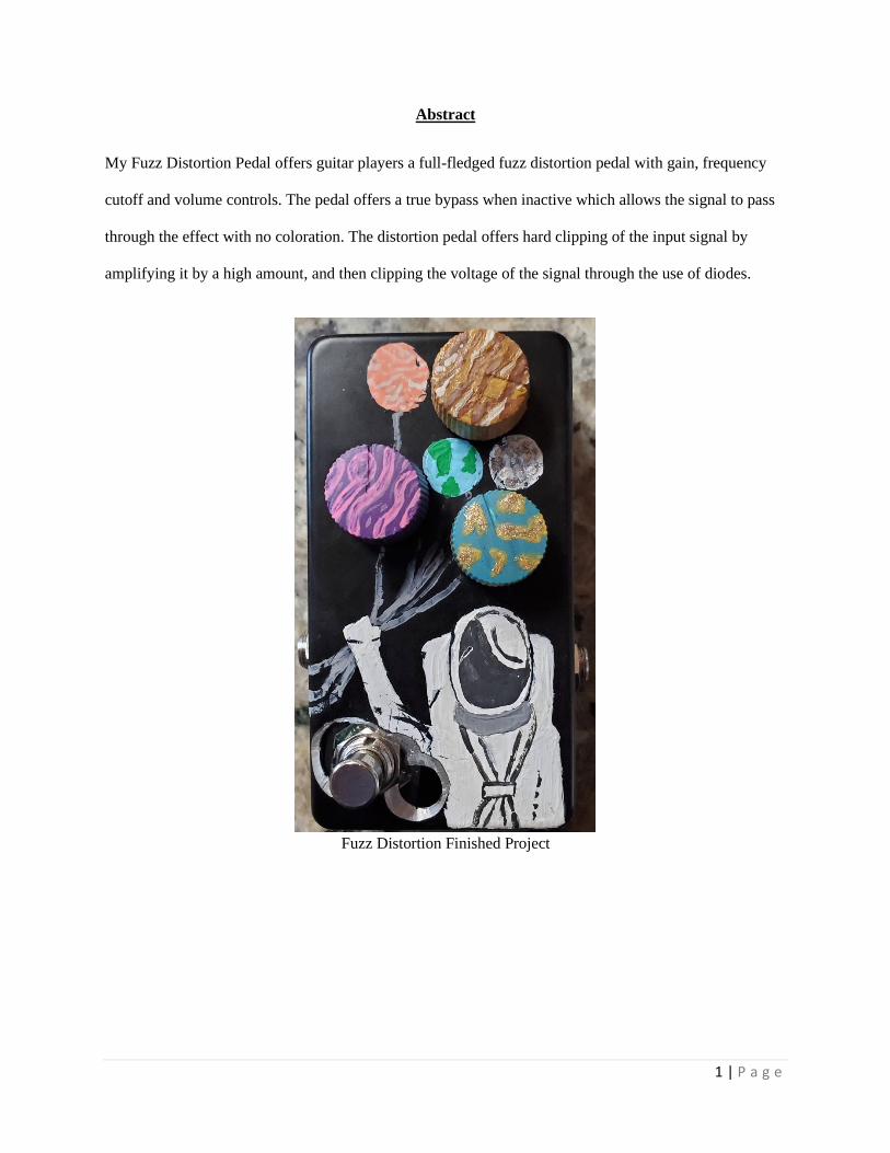
My Fuzz Distortion Pedal offers guitar players a full-fledged fuzz distortion pedal with gain, frequency
cutoff and volume controls. The pedal offers a true bypass when inactive which allows the signal to pass
through the effect with no coloration. The distortion pedal offers hard clipping of the input signal by
amplifying it by a high amount, and then clipping the voltage of the signal through the use of diodes.
Fuzz Distortion Finished Project
2 | P a g e
Chapter 1: Introduction
Effects for electric guitars began appearing in the 1960’s alongside the rise in popularity of Rock
and Roll. Musicians such as Jimi Hendrix, The Beatles and The Rolling Stones achieved some of their
signature sounds through the use of stompbox guitar pedals [1]. Stompbox pedals activate via foot
switches and affect the sound of an electric instrument. One of the first popular effects was the Arbiter
Fuzz face which distorted the guitar’s sound and gave birth to “Fuzz pedals” [6]. Fuzz pedals are
characterized by the shape of their output waves. All fuzzes produce square waves at their output by hard-
clipping their sinusoidal inputs [1,4] to produce a grainy distorted sound that sustains volume much
longer than other signals.
As an electric guitar player with over ten years of experience, I know that guitar players are very
particular about their tone or sound. Some serious players spend upwards of $300 on a single effects unit
if it provides them with the right tonal capabilities [8]. Additionally guitarists spend large amounts of
money on “boutique” pedals [8]. Boutique pedals require hand assembly by either a single person, or a
small group of people. The relatively low cost of the components required to implement the circuits [10]
along with the ease of assembly after design completion, provides a great potential for profit. A popular
design provides engineers such as myself with an opportunity to make extra money in my free time.
The majority of popular fuzz pedals use transistors to make their gain stages [8]. In light of this
fact, the “Fuzz Distortion and Total Frequency Booster” implements its gain stages using op-amps. By
using op amps to provide the gain for the device I am able to provide customers with a unique design with
unique sonic characteristics. Modern audio op-amps provide high amounts of gain with low amounts of
noise [5] and would make for a quality sounding pedal when designed correctly.
Overall this project serves as a low risk, high reward endeavor into entrepreneurship. Not much
risk associates with the cost of developing a guitar pedal like the “Fuzz Distortion and Total Frequency
Booster”. I have always wanted to build my own guitar effect, as it will be gratifying to use a device that I
3 | P a g e
designed myself which provides the main motivation behind choosing this project. Couple this desire with
the potential for high profit in return for a small amount of work and you have a project with massive
amounts of upside.
Chapter 2: Customer Needs, Requirements, Specifications
Customer Needs Assessment
To develop customer needs, I began examining the guitar pedals I own as well as viewing others I do not
own online. First the pedal must provide quality tonal characteristics to the user, and must sound good.
The pedal’s sound stands as the main selling point, making it vital it sounds good. Next, it should utilize a
durable design to ensure the product has a long working lifetime. Due to their design pedals lay on the
floor and footswitches engage or disengage the effect. This means the device chassis and the switch must
have a robust design to withstand continued hard use.
The next three requirements make the pedal competitive with other pedals available. Most importantly the
pedal uses standard sized cables for power input and signal flow to allow interfacing and integration of
other pedals. Guitarists prefer small size in order to not take too much room on stage. Because some
stages lack space, making small pedals ideal. Finally a cheap production cost ensures a final price within
a reasonable range comparable to similar pedals.
Requirements and Specifications
The first specification: the pedal must have a low pass filter that’s user controlled to cut harsh,
high frequency harmonics from the output signal, ensuring a tone and sound that’s pleasant and not ear
splitting. For the second spec, I measured standard Boss pedal sizes to find a size that’s in line with other
popular pedals. I settled on measuring Boss pedals because Boss began designing and selling pedals over
50+ years ago and continue as one of the premier pedal builders.
4 | P a g e
For power and signal flow connections, the pedal must use standard connections assumed already
owned by owner. Standard electric guitar cables utilize 1 ¼ “instrument cables. Standard pedals obtain
power through either 9V batteries, or 9V adapters. Since the pedal may obtain power differently based on
the usage situation, it’s vital the pedal can run off a battery or a connected 9V power supply.
Finally the device construction makes use of aluminum. Most guitar pedal chassis use aluminum.
Aluminum has proven durable enough to withstand constant usage. Using aluminum ensures the chassis
price remains low which helps keep the production price low.
Table I below lists marketing requirements and performance specifications for the project.
Marketing requirements guide the functionality requirements of the pedal. I base these requirements on
research [7,8] and knowledge gained as a guitar player for 10+ years. Each marketing requirement drives
specifications for the proper functionality of the device.
TABLE I
Fuzz Distortion Specifications and Marketing Requirements
Marketing
Requirements
Engineering
Specifications
Justification
1,4 Attenuate frequencies greater than 20
kHz by 3 dB or more
Frequencies above 20 kHz inaudible but
still draw power [1]
1,3 Output low pass filtered If too many high frequencies present in
output signal, the output can sound harsh
and unpleasant [4]

5 | P a g e
Marketing
Requirements
Engineering
Specifications
Justification
1,3 Output low pass filter has variable
corner frequency between 15 and 20 kHz
Output filter has an adjustable corner
frequency to control high frequencies
present in output signal [1]
1,3 Output filter applies 3 dB or more of
attenuation to frequencies equal or
greater than the corner frequency.
Standard corner frequency attenuation
5 Enclosure size not to exceed
66mm x 121mm x 40mm
Standard sized pedals meet space
requirements on gigs
3,4 Input and Output jacks utilize ¼”
instrument cables
Standard guitars utilize ¼” diameter
instrument cables
3,4 Operates via a 9V battery or 9V AC-DC
adapter
Standard guitar pedals powered from a
9V supply [5]
3 Effect toggled On/Off via a footswitch Guitar players require both hands to play
correctly
2 Aluminum device chassis Ensures a durable enclosure able to
handle gigging, travel and constant usage
4 Production cost less under $100 Ensures the final price to customers
remains in line with the standard pedal
price of $100-$200

6 | P a g e
Marketing
Requirements
Engineering
Specifications
Justification
1 Hard clips input signal Fuzz pedals categorized by hard clipping
of input signal [1,3,7,10]
1 Input signal uses true bypass when effect
switched off
Allows natural sound of input signal to
pass through the effect when not in use
Marketing Requirements
1. Quality Tone
2. Durable Design
3. Standard Connections
4. Cheap
5. Small
In order to ensure that project completion before graduation, Table II lists a set of due dates for
important deliverables over the life cycle of the project. All dates are tentative and subject to change as
the project progresses.
TABLE II
FUZZ DISTORTION DELIVERABLES DUE DATES
Delivery Date Deliverable Description
Design Review
3/6/2019 EE 461 demo

7 | P a g e
Delivery Date Deliverable Description
3/13/2020 EE 461 report
5/28/2019 EE 462 demo
11/4/2019 ABET Sr. Project Analysis
5/29/2020 Sr. Project Expo Poster
6/5/2020 EE 462 Report
With product functionality constrained and defined, the next chapter provides information on how
the pedal implements the desired functionality.
Chapter 3: Functional Decomposition
The Fuzz Distortion block diagram demonstrates the basic functionality of the pedal. Gain,
Volume and Tone rely on potentiometers to change the sound effect. Gain determines amount of clipping
on output signal [7,10,1]. Volume affects the volume level, and tone allows the user to adjust the corner
frequency of a low pass filter on the output of the pedal [1]. Proper functionality requires an On/Off
switch for engaging and disengaging the effect as well as a power supply input for the circuit [3]. Finally
the pedal must have a soundwave to act upon so the Guitar In input provides the soundwave to operate on.
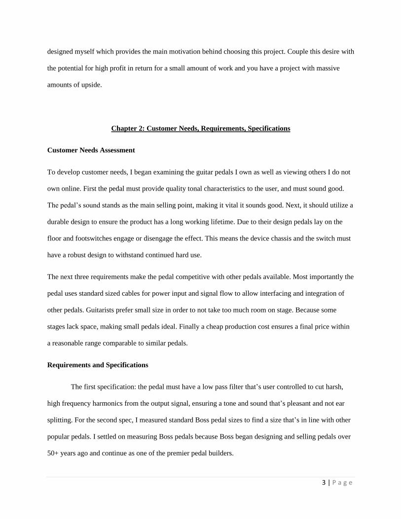
Figure 1 displays the level 0 funcitonality of the pedal. All level 0 inputs to the circuit will be
controllable by the end user. Table III lists the function of all level 0 inputs and provides a better
understanding of what role each input plays.
8 | P a g e
Figure 1: Fuzz Distortion Level 0 Block Diagram
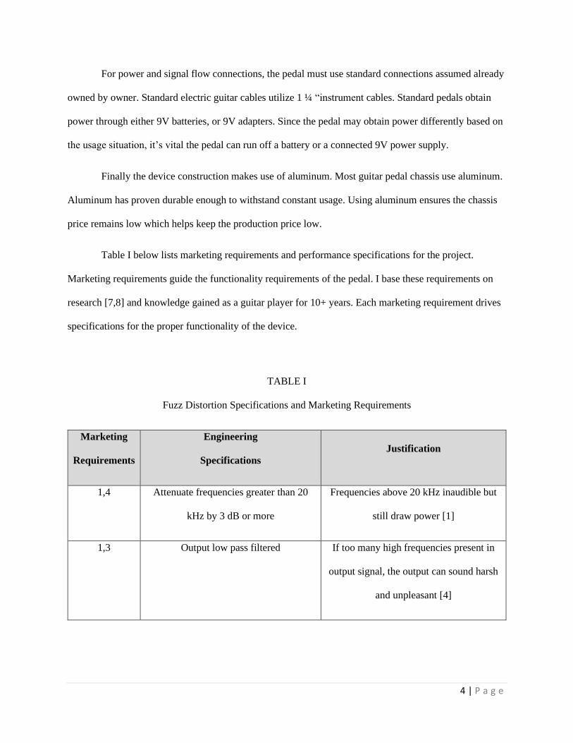
Figure 2: Fuzz Distortion Full Schematic
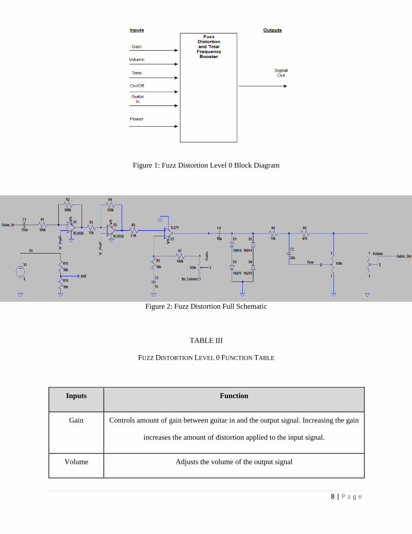
TABLE III
FUZZ DISTORTION LEVEL 0 FUNCTION TABLE
Inputs Function
Gain Controls amount of gain between guitar in and the output signal. Increasing the gain
increases the amount of distortion applied to the input signal.
Volume Adjusts the volume of the output signal

9 | P a g e
Inputs Function
Tone Controls the cutoff frequency of a high pass filter applied to the output signal.
Turning the tone all the way off sets the corner frequency of the filter at its lowest
value. This cuts the most high end out of the output signal
On/Off Toggles effect active or inactive
Power Supplies power for the circuit
Guitar In Provides the signal that the effect operates on
Outputs Function
Output Signal Signal output after effect
Total
Functionality
The unit receives a guitar signal at its input. The signal is processed and turned from
a sinusoid into a square wave. The amount of clipping on the output signal, as well as
its volume and tonal content can be controlled with the gain, volume and tone inputs.

10 | P a g e
Figure 3: Fuzz Distortion Level 1 Block Diagram
Figure 3 provides the Level 1 block diagram which provides a deeper look into the functionality
of my design. Figure 2 shows the basic stages of signal processing and power distribution throughout the
pedal [1]. Tables IV, Table V, Table VI and Table VII provide the descriptions of the functionality of
each block as well as descriptions of the blocks’ inputs and outputs.
TABLE IV
Gain Stage Function Table
Gain Stage
Inputs Function
Gain Controls amount of gain applied to Guitar In. Affects the amount of signal
clipping
Guitar In Provides the signal that the effect operates on
11 | P a g e
Inputs Function
Power Provides power to circuitry
Outputs
Guitar Signal Amplified output signal
Total
Functionality
Provides amplification and user controlled clipping of input signal
The gain applied to the input guitar signal is provided via a 3 stage amplifier utilizing 1 RC4558
Dual Op-amp chip in series with 1 TL071 Single Op-amp chip. The RC4558 Op-amp is configured as 2
inverting amplifiers which when placed in series provide a signal gain of AV = (-AV1 * -AV2). The fact that
both stages provide negative means that the final voltage gain is positive in value. To find the gain of each
stage I used the gain equation of inverting amplifiers which is AV = -(R2/R1) where R2 is the resistor
between the inverting input of the op-amp and R1 is the resistor connected between the input signal and
the inverting input. The positive input of the inverting op-amp is connected to a virtual ground that is
located at half of the full power supply voltage. This bias voltage is critical as it allows the output signal
to be biased in the middle of the power supply allowing for maximum voltage swing in both the positive
and negative directions.

12 | P a g e
Figure 4: Fuzz Distortion Gain Stage Schematic
By referencing Figure 4, we can calculate the gain of each stage of the RC4558 chip.
AV1 = -(680k/100k) = -6.8 and AV2 = -(100k/10k) = -10. Combined together, the gain after the first two
stages is 68. The value of 100k was chosen for the input of the first stage in order to not load the pickups
of the electric guitar which could decrease performance. The 3rd stage of the gain section was
implemented using a single TL071 op-amp in a non-inverting configuration. The gain equation for a non-
inverting op-amp is given as AV = 1 + (R2/R1) where R2 is connected from the op-amp output to the
inverting input, and R1 is connected between the inverting input and a grounded capacitor meant to filter
out DC noise from the ground node. By examining Figure 4 we can find that R2 has a variable value
between 100k and 600k determined by the series combination of a 100k resistor and a 500k
potentiometer. The potentiometer provides control of overall gain to the user as labeled in Figure 1 and
Figure 3. Looking at Figure 4 we can find that R1 has a value of 10k and is connected to a 1uF
decoupling capacitor. Using these values we find that AV3 has a range between 11 and 61. To find the
overall gain of the gain section we use the equation AV(Total) = -AV1 * -AV2 * AV3. The maximum and
minimum gain values are given in Table V.

13 | P a g e
Table V
Maximum and Minimum Gain Values
AV1 AV2 AV3 AV(Total)
Maximum Gain -6.8 -10 11 748
Minimum Gain -6.8 -10 61 4,148
The same gain could have been achieved using all of the op-amps in non-inverting designs, but the choice
was made to use inverting designs for the first 2 stages in order to cut down on the number of components
needed. Each non-inverting stage requires an extra decoupling capacitor to connect R1 to ground. The
final portion of the gain stage is made up of a 10uF capacitor connecting the output of the 3rd op-amp to a
series of 4 diodes connected to ground. The 10uF capacitor is there to remove the 4.5 V DC bias
introduced to the signal by the virtual ground in stages 1 and 2. The diodes serve the purpose of clipping
the signal to give it the signature sound of a fuzz pedal. Multiple combinations of diodes were tested in
order to eventually find the combination used in the final design. At first I tested only germanium diodes
as many people believe they have a warmer sound than more common silicon diodes. This believed to be
a product of their lower turn on voltage of 0.3V compared to the 0.7V turn on voltage of most silicon
diodes [6]. The germanium diodes I tested included the 1N270, the 1N60P and the 1N34A. However, I
found that the germanium diodes’ clipping was too soft for my tastes and didn’t sound right for what I
had in mind. I then tested 1N914 silicon diodes which got me closer to the sound I was looking for, but
they were too harsh. I finally tested a combination of 1N914 silicon diodes in series with different
germanium diodes and settled on the combination of 1N914’s with 1N270’s. This combination gave me a
sound somewhere in the middle of the germanium only and silicon only designs.
14 | P a g e
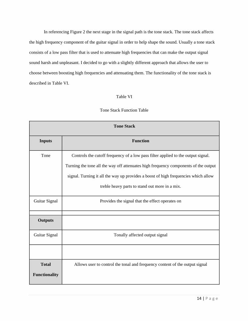
In referencing Figure 2 the next stage in the signal path is the tone stack. The tone stack affects
the high frequency component of the guitar signal in order to help shape the sound. Usually a tone stack
consists of a low pass filter that is used to attenuate high frequencies that can make the output signal
sound harsh and unpleasant. I decided to go with a slightly different approach that allows the user to
choose between boosting high frequencies and attenuating them. The functionality of the tone stack is
described in Table VI.
Table VI
Tone Stack Function Table
Tone Stack
Inputs Function
Tone Controls the cutoff frequency of a low pass filter applied to the output signal.
Turning the tone all the way off attenuates high frequency components of the output
signal. Turning it all the way up provides a boost of high frequencies which allow
treble heavy parts to stand out more in a mix.
Guitar Signal Provides the signal that the effect operates on
Outputs
Guitar Signal Tonally affected output signal
Total
Functionality
Allows user to control the tonal and frequency content of the output signal

15 | P a g e
The design for the tone stack can be seen in Figure 5 below. This design was chosen because
allowing the user to boost or attenuate frequencies gives them more freedom to shape their sound
depending on what they are playing. When playing guitar solos or treble heavy riffs and parts on the
higher strings, boosting the higher frequencies allows the guitar to stand out when played in a mix with
other instruments.
Figure 5: Tone stack design schematic
In contrast, when playing mid or bass frequency heavy parts, the user may want to attenuate the
higher frequency overtones to tighten up their sound. The tone control mentioned in Figure 1 is
implemented via the potentiometer seen in Figure 5. When the knob is turned all the way up, and
resistance of the potentiometer is completely between pins 2 and 3, high frequencies are boosted allowing
them to stand out more. This can be seen in Figure 6 where frequencies above the high E string (330 Hz)
receive the greatest boost.
Figure 6: Frequency response from 50 Hz to 2 kHz of tone stack in the fully turned up position
16 | P a g e
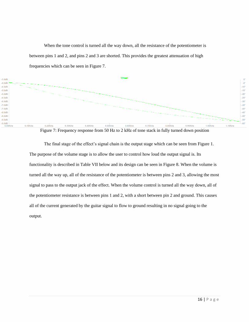
When the tone control is turned all the way down, all the resistance of the potentiometer is
between pins 1 and 2, and pins 2 and 3 are shorted. This provides the greatest attenuation of high
frequencies which can be seen in Figure 7.
Figure 7: Frequency response from 50 Hz to 2 kHz of tone stack in fully turned down position
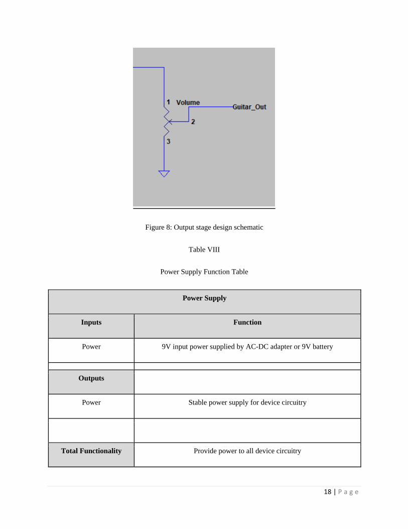
The final stage of the effect’s signal chain is the output stage which can be seen from Figure 1.
The purpose of the volume stage is to allow the user to control how loud the output signal is. Its
functionality is described in Table VII below and its design can be seen in Figure 8. When the volume is
turned all the way up, all of the resistance of the potentiometer is between pins 2 and 3, allowing the most
signal to pass to the output jack of the effect. When the volume control is turned all the way down, all of
the potentiometer resistance is between pins 1 and 2, with a short between pin 2 and ground. This causes
all of the current generated by the guitar signal to flow to ground resulting in no signal going to the
output.

17 | P a g e
Table VII
Output Stage Function Table
Output Stage
Inputs Function
Volume Varies the volume of the output signal
Guitar Signal Provides the signal that the effect operates on
Outputs
Output Signal Final output signal
Total Functionality Provides a stable final output signal with variable volume
18 | P a g e
Figure 8: Output stage design schematic
Table VIII
Power Supply Function Table
Power Supply
Inputs Function
Power 9V input power supplied by AC-DC adapter or 9V battery
Outputs
Power Stable power supply for device circuitry
Total Functionality Provide power to all device circuitry
19 | P a g e
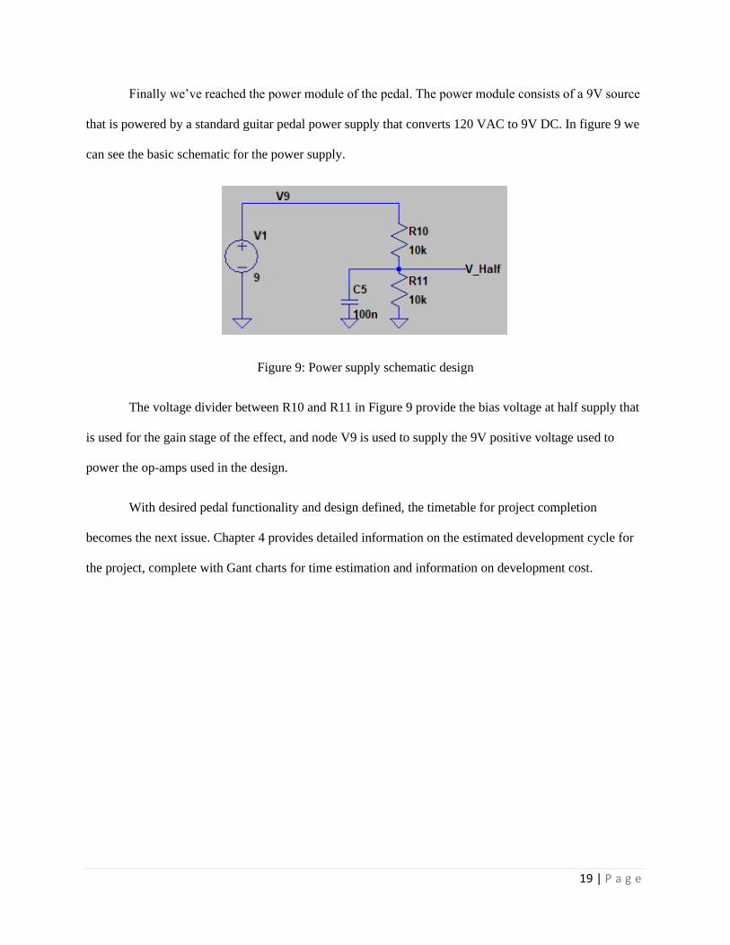
Finally we’ve reached the power module of the pedal. The power module consists of a 9V source
that is powered by a standard guitar pedal power supply that converts 120 VAC to 9V DC. In figure 9 we
can see the basic schematic for the power supply.
Figure 9: Power supply schematic design
The voltage divider between R10 and R11 in Figure 9 provide the bias voltage at half supply that
is used for the gain stage of the effect, and node V9 is used to supply the 9V positive voltage used to
power the op-amps used in the design.
With desired pedal functionality and design defined, the timetable for project completion
becomes the next issue. Chapter 4 provides detailed information on the estimated development cycle for
the project, complete with Gant charts for time estimation and information on development cost.
20 | P a g e
Chapter 4: Project Planning
Winter 2020
Spring 2020
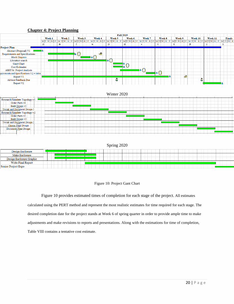
Figure 10: Project Gant Chart
Figure 10 provides estimated times of completion for each stage of the project. All estimates
calculated using the PERT method and represent the most realistic estimates for time required for each stage. The
desired completion date for the project stands at Week 6 of spring quarter in order to provide ample time to make
adjustments and make revisions to reports and presentations. Along with the estimations for time of completion,
Table VIII contains a tentative cost estimate.
21 | P a g e
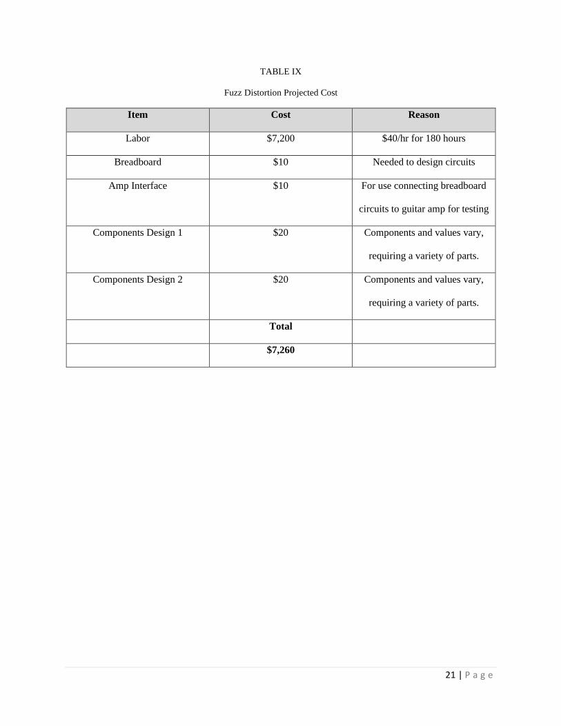
TABLE IX
Fuzz Distortion Projected Cost
Item Cost Reason
Labor $7,200 $40/hr for 180 hours
Breadboard $10 Needed to design circuits
Amp Interface $10 For use connecting breadboard
circuits to guitar amp for testing
Components Design 1 $20 Components and values vary,
requiring a variety of parts.
Components Design 2 $20 Components and values vary,
requiring a variety of parts.
Total
$7,260

22 | P a g e
References
1. C. Anderton, Electronic projects for musicians. Place of publication not identified: Music
Sales Corp, 2003.
2. R. C. D. Paiva, S. D'Angelo, J. Pakarinen and V. Valimaki, "Emulation of Operational
Amplifiers and Diodes in Audio Distortion Circuits," in IEEE Transactions on Circuits and
Systems II: Express Briefs, vol. 59, no. 10, pp. 688-692, Oct. 2012.
doi: 10.1109/TCSII.2012.2213358URL:
http://ieeexplore.ieee.org.ezproxy.lib.calpoly.edu/stamp/stamp.jsp?tp=&arnumber=6308712&isn
umber=6329981
3. K. Schaefer, “Fuzz Pedal Design Project,” Digital Commons: Cal Poly, Mar-2014. [Online].
Available:
http://digitalcommons.calpoly.edu/cgi/viewcontent.cgi?article=1054&context=bmedsp.
[Accessed: 18-Oct-2019].
4. R. Salminen, General Guitar Gadgets, 2000. [Online]. Available:
http://www.generalguitargadgets.com/how-to-build-it/technical-help/articles/design-
distortion/. [Accessed: 18-Oct-2019].
5. “RC4558 Dual General-Purpose Operational Amplifier Data Sheet.” Texas Instruments, Oct-
2014. http://www.ti.com/lit/ds/symlink/rc4558.pdf [Accessed: 18-Oct-2019]
6. “Fuzz Face,” Wikipedia, 01-Oct-2019. [Online]. Available:
https://en.wikipedia.org/wiki/Fuzz_Face. [Accessed: 18-Oct-2019].
7. “The Future is Fuzzy” B. Wampler and B. Wyland, “Wampler Pedals,” Wampler Pedals, 07-
Oct-2019.
8. “Fuzz Shootout: The 5 Most Popular Fuzz Pedals on Reverb | Reverb Demo” Reverb. 29-
Mar-2017.

23 | P a g e
9. J. Wolfert, “Germanium vs. Silicon,” reverb.com, 21-Dec-2018. [Online]. Available:
https://reverb.com/news/germanium-vs-silicon. [Accessed: 18-Oct-2019].
10. R. Sarafan, “Build Your Own Guitar Fuzz Pedal,” Build Your Own Guitar Fuzz Pedal.
[Online]. Available: https://www.jameco.com/Jameco/workshop/JamecoBuilds/fuzz-
pedal.html. [Accessed: 18-Oct-2019].
Appendix A: Senior Project Analysis
1.) The fuzz distortion electric guitar stomp box effect toggles on and off via a foot activated switch.
The effect takes the input signal, amplifies it and then clips the signal and outputs it to the
amplifier.
2.) Primary constraints that affect my design: having enough space and shaping the tonal
characteristics and space. I have limited space in my design and which causes difficulty in fitting
all of the components and the circuit board inside the enclosure. Shaping the tonal characteristics
proves much more difficult as no way exists to perform calculations or simulations to determine
what sounds good and what doesn’t. This means that almost all of my testing requires testing in
hardware.
3.) The overarching economic impact of this project lacks severity. The pedal stands no chance to
take anybody’s job or change the economy. Effect on natural resources stands as the greatest
economic impact due to mass production of the device components already existing.

24 | P a g e
The majority of the costs for the project accrue during the development stage. Devices require no
maintenance after purchase.
The project requires few components. It takes resistors, potentiometers, capacitors, op-amps, a
circuit board, and a metal enclosure. $200 stands as the projected project development cost.
Majority of cost comes in equipment needed for testing. This equipment includes a microphone,
and sheet for building a bread board setup that can plug into a guitar amp. All project costs
delegate to myself.
The project should produce about $100 in profit per unit, going directly to me.
Timing of product emergence carries little importance as guitar pedal demand remains consistent
year round. Ideally the pedal should last forever while used properly and not abused. I know
people who have 30 year old guitar pedals.
The project should take about 2 and a half months to compete once the actual design progress
begins.
4.) The goal for sales stands at 75 units per month. Ideally single unit production remains under $50.
After finalizing the design, a unit requires 2 hours to assemble by hand. If utilizing outside help to
produce units, assume $20 per hour as a reasonable wage, thus increasing cost to $50. This
includes electrical components, enclosure and graphic design. Reasonable prices for customers
desired. Suggested retail price stands at $150. $150 falls in the standard pedal range of $100-$200
dollars and provides a healthy profit of $100 per unit sold. At a sales rate, 75 units per month this
would produce a revenue of $7500 per month to myself. The Sale rate remains plausible for the
first 6 months to a year after the product hits the market, at which point sales likely begin falling

25 | P a g e
off due to market momentum loss, and availability of enough units available for a used market.
So first the first production year we could hope for a yearly profit: $7500/month * 12 months =
$90,000. This figure doesn’t include advertising costs
5.) Harvesting the components natural resources and the enclosure make the majority of the
environmental impact. Environmental strain doesn’t increase much due to mass production of all
materials. China’s eco system sees the most effect as most of the world’s silicon mines reside
there. The largest negative silicon mining byproduct’s the expulsion atmospheric CO2.
6.) I expect during the production of the product. Production merely requires soldering and
producing a metal enclosure, relatively easy tasks.
7.) Device maintenance simply requires keeping it dry, and protecting against shock. If used properly
it should last 30 years. I chose 30 years as there’s a plethora of 1980s guitar pedals still available
for purchase that function correctly.
The project doesn’t have a large impact on the sustainable use of natural resources. As stated in
section 6, the materials used to produce the product are all manufactured on extremely large
scales.
All design upgrades largely subjective to the tonal preferences of a given user.
8.) The project’s ethical value’s determined when viewed through different ethical frameworks. One
applicable framework for this project’s the framework Ethical Egoism which believes humans

26 | P a g e
ought to act in self-interest. In this case the Fuzz Distortion Pedal displays a great example of
how acting in one’s interest. Since I’m one who stands to make financial gains in the initial
product production and later a few employees. It’s strongly in my interest to begin this endeavor.
After finishing the initial prototype and producing proper documentation the project likely takes
~2 hours to produce one unit by hand. Total profits per unit estimate roughly $140 per unit I
produce. The materials cost about $10 after bulk purchase. This means I make roughly $70 per
hour when working on pedals thus securing a very good wage. The fact these projects can
complete their design cycle during free time outside a normal job’s also very beneficial to me. It
allows me to make extra money. Overall according to Ethical Egoism, I have no reason to not
complete this project.
When viewed through the IEEE Code of Ethics my project meets all agreements. As stated above,
my final product poses no health risks and I have no involvement in a conflict of interest working
on the project. My project makes no unrealistic claims in my project plan and I 100% guarantee
the project does what it says it does. I’m accepting no bribes, I accept and welcome criticism of
my work, plan to fix all errors caused by myself and properly credit all who have contributed to
my project. I sell my product to all and do not discriminate based on any criteria except terrible
moral behavior from specific individuals.
9.) Currently no health or safety concerns exist with product use. The product runs 9V and doesn’t
operate high frequencies which might affect users and those around the device. The largest safety
concerns with my project manufacturing include the component soldering and producing the
metal enclosure. Soldering’s potentially dangerous as due to heat involvement in the process,
however all employees require soldering proficiency and safety skills. The metal enclosure
production provides more danger than the soldering. In order to produce the metal enclosure
properly sheet metal needs bending and shaping using large presses, and drills to make control
27 | P a g e
knob openings connecting to the circuit. Like soldering, the manufacturer possesses safety
knowledge.
10.) The manufacture and sale of the product minimally affects social and political issues, but some
could arise from the use of it. The product’s a musical device so a possibility exists a song using
the device could have societal and political impact. While not likely the device would get any
credit for the actual political or societal impact from any songs it might influence.
Guitar players and companies producing guitar pedals stand as the largest group affected by this
product. Other guitar pedal companies and I have the most stake in the project since we’re the
only ones with money involved. For myself the stakes are low, if nobody buys my pedal then I
have a unique piece of equipment that I enjoy using. The project possesses low risk due to the
production of this product. I produce all units until demand greatly increases. It then follows that I
wouldn’t steal too much market share from other pedal companies. Also, buying my product
doesn’t necessarily mean the customers buy no other company’s pedals. Most guitar players own
pedals from many different brands. However, if my design becomes popular I would consider
designing other pedals and could myself starting a pedal business. If this occurs then other pedal
companies would stand to lose much more. If a company produces only one pedal then they can’t
make much of a dent in the sales of companies that sell multiple pedals. If a company produces a
wide range of pedals, other companies stand much more of a chance to lose customers. As the
number of pedals produced grows, the threat to the profits of other companies increases. By
having a full line of pedals, a company provides its self with the opportunity to meet all the pedal
needs of a given customer, thus eliminating the need for other companies.
28 | P a g e
11.) During the planning process for this project I learned to create a proper document detailing the
development and large scale product idea. I also learned how to perform asymmetrical clipping
signal clipping using different numbers of diodes to clip the input signal.


![Parameter Guide - Roland Corporation · 2020. 9. 10. · The STOMPBOX select window appears. 5 Turn knob [5] to select the STOMPBOX type. 6 Press the [5] knob. Editing the STOMPBOX](https://static.documents.pub/doc/80x56/6111afc81e03315bdf0cf3c1/parameter-guide-roland-corporation-2020-9-10-the-stompbox-select-window-appears.jpg)


