AbstractThe current study challenges the multi-objective optimization of electric discharge machining (EDM) parameters. EDM is used for creating profiles by machining of workpiece that are difficult to machine by conventional method. In the current work four responses such as material removal rate (production rate), tool wear rate, surface roughness (quality) and circularity (profile) are collectively investigated with varying controlling parameters. The human decision for best combination of controlling parameters for highest performance has uncertainties, which results in inferior solution. The multiple responses along with uncertainties and impreciseness can be addressed by combining a neuro-fuzzy system with particle swarm optimization (PSO). To illustrate the superiority of the proposed approach a set of experiment have been conducted in EDM process using AISI D2 tool steel as workpiece and brass tool. The experimental plan was made according to the Box-Behnken response surface methodology design with four process parameters namely discharge current, pulse-on-time, duty factor, and flushing pressure. The four response parameters such as material removal rate, tool wear rate, surface roughness, and circularity of machined components were optimized simultaneously. One unique Multi-response Performance Characteristic Index was obtained by combining the four responses using the proposed neuro-fuzzy technique. A regression model was developed on single response and optimized by PSO to obtain the optimal parameter setting. An experiment was conducted on optimal parameter to test the optimum performance. It is observed that the EDM responses were affected significantly by discharge current and pulse-on-time. The increase in pulse-on-time leads to larger surface cracks and more micro-pores on the machined surface.
* Jambeswar Sahu, [email protected] | 1School of Mechanical Engineering, Vellore Institute of Technology, Vellore, Tamil Nadu 632014, India. 2School of Electrical Engineering, Vellore Institute of Technology, Vellore, Tamil Nadu 632014, India.
Article Highlights
• RSM was proven to be an effective statistical tool for reducing the experimental runs, and also establishes the relation between multiple inputs and single output.
• The neuro-fuzzy system combined with PSO results a suitable model to convert multiple response into an equivalent single response.
• The presented approach can be a practical method for situations where multiple conflicting objectives are needed to be optimized at the same time.
Research Article SN Applied Sciences (2021) 3:701 | https://doi.org/10.1007/s42452-021-04668-4
1 Introduction
The Electrical Discharge Machining (EDM) is a state of the art machining process. EDM is chosen over the conven-tional machining processes which are unable to cut the high strength to weight ratio and toughened conductive materials. In the EDM process a series of electric sparks is established between the tool and the workpiece caus-ing the removal of material through controlled erosion. The thermal energy produced due to spark melts and vaporizes the workpiece material. The EDM process finds diversified applications in aerospace, ordnance, and auto-mobile industries [1]. The complexity of the EDM process results in difficulty to establish the relation between the process parameters and their responses. However, the pro-cess performance measures such as material removal rate (MRR), tool wear rate (TWR), surface roughness
(Ra) , and
circularity (r1∕r2
) have been considered for performance
analysis [2]. Many process parameters influence the above-mentioned responses in differnt ways. Parameters such as discharge current
(IP) , pulse-on-time
(Ton
),duty factor
(τ) , and flushing pressure (fP) significantly affect the EDM
process [3].In this work, four control parameters IP,Ton , τ , and fP at
three levels were considered for the investigation. The experimental runs were reduced by utilizing the Box-Behnken design of response surface methodology (RSM) without losing the accuracy of data [4, 5]. According to Box-Behnken design (four-factor three-level) twenty-seven experimental runs were conducted where the runtime of each experiment was one hour. In most of the earlier applications of RSM, optimization was carried for a single response. However, it can be extended for multi-ple response optimization [6, 7]. The responses can be of three types namely larger-the-best, nominal-the-best and smaller-the-best. Most of the engineering applications or physical processes encounter multiple responses which are often conflicting in nature [8].
In the multiple response optimization problems, it is a usual practice to convert multiple responses into an equiv-alent single unique response via multi-attribute decision-making process. The fuzzy decision-making approach and fuzzy with Taguchi experimental design was used to deal with the multi-response optimization problems [9, 10]. In the fuzzy theory the concept of membership function used to deal with inexact information obtained through the experimental process instead of crisp variables. It is dif-ficult to find out the most suitable membership functions for the experimental data and developing the rule base required for the inference engine. In this research work, the neuro-fuzzy system was employed on the experimen-tal data for obtaining a single unique equivalent response
for four performance characteristics of the EDM process. The AISI D2 tool steel was considered as work material, which is hard to machine using conventional machine tools. Brass was considered as tool material, due to good conductivity and less erosion property. The proposed neuro-fuzzy system produces a single response, known as Multiple Performance Characteristic Index (MPCI). The relation between the MPCI and controlling process param-eters were articulated mathematically by considering MPCI as a single response. A regression analysis was carried out using RSM design to obtain the regression equation. Fur-ther, PSO has been utilized to retrieve the most suitable parametric combination that maximizes the MPCI [11].
The performance enhancement in EDM is a well-researched area. However, finding the best suitable machining parameters for finest performance in EDM is a challenging task. Lee and Li [12] studied the influence of parameters such as gap voltage, discharge current, pulse duration, pulse interval, and flushing pressure on the rate of material removal, wear rate of the tool, and surface roughness of EDM process. They used tungsten carbide (WC) as workpiece and copper tungsten (CuW) as electrode material. Tebin et al. [13] experimented on EDM to study the effect of discharge current, the pulse-on duration, the pulse-off duration, the tool electrode gap, and the tool material on MRR and TWR using steel 50CrV4 as workpiece, copper, and graphite as a tool. The effect of EDM machining parameters such as pulse cur-rent, gap voltage, and pulse-on-time on MRR and TWR was investigated by Habib [14] using RSM design. The MRR and TWR values were increased with increasing val-ues of process parameters. Singh et al. [15] conducted experiments on EDM to obtained MRR, TWR, Ra, and ana-lyzed the variation in responses with peak current, gap voltage, pulse-on-time, and duty cycle. RSM design was used to conduct experiments on EDM by Pradhan and Bis-was [16]. They investigated the effect of four controllable input variables such as discharge current, pulse duration, pulse-off-time, and voltage on machining performance of AISI D2 steel and copper as work piece-tool combina-tion. It is observed that the discharge current and pulse-on-time have a significant effect on surface roughness. Helmi et al. [17] investigated the surface roughness and MRR in the electro discharge grinding process employ-ing the Taguchi method when tool steel is machined with brass and copper electrodes. They found that, peak cur-rent and pulse-on-time were the important parameters influencing the performance characteristics. Chattopad-hyay et al. [18] proposed a design of experiment (DOE) method to experiment on rotary EDM with EN8 steel and copper as work piece-tool pair. The relations between per-formance characteristics (MRR and Electrode Wear Rate) and process parameters (peak current, pulse-on-time and
Vol.:(0123456789)
SN Applied Sciences (2021) 3:701 | https://doi.org/10.1007/s42452-021-04668-4 Research Article
rotational speed of electrode) was established. The peak current and rotational speed of the tool have a significant effect on both the responses. Regression models and DOE approaches have been employed extensively in the EDM process to obtain the best machining parameters [7, 19, 20]. The DOE approaches are well suited to obtain optimal parametric combinations for a single response problem. The method breaks down when multiple responses are simultaneously optimized. In this direction, a fuzzy TOPSIS approach was proposed to convert multi-responses into a single response [9].
A combination of Genetic algorithm (GA) and artifi-cial neural network (ANN) was employed to retrieve best suited process parameters to improve performance in EDM process by utilizing graphite as a tool and nickel-based alloy as a work piece [21]. A similar approach has been considered by Su et al. in [22] from the rough cutting to the finish cutting stage. In most of the studies, multiple objectives are transformed into a unique single objective and attempt to find optimal parameters. To solve the sin-gle response optimization problem of Taguchi approach, Liao [23] proposed an effective method named as PCR-TOPSIS which is a combination of process capability ratio (PCR) and TOPSIS theories. Singh et al. [24] used the adap-tive neuro-fuzzy inference system for predictive analysis of EDM responses. The MRR and Ra in the EDM process were optimized using ANN with PSO [25]. Last few decade researchers are attracted towards artificial intelligence (AI) techniques such as ANN, GA, and fuzzy logic, to model and optimize the manufacturing processes. These new techniques can minimize the few limitations of the tradi-tional process modeling approaches. To optimize multi-ple responses a neuro-fuzzy system was used by Antony et al. [8]. A combination of back propagation neural net-work (BPNN) with Levenberg Marquardt (LM) algorithm was used by Panda and Bhoi [26] to predict MRR. The AI technique such as simulated annealing (SA), ANN, genetic algorithm (GA) were utilized to optimize EDM process parameters [27, 28].
PSO is a computational simulation technique based on the movement of organisms such as gather of birds and groups of fish used to solve optimization problems [29]. PSO has a populace of search points to investigate the search space which is referred to as a ‘particle’ and the particles represent a potential solution. The best solution is known as a fitness function value [30]. Particles having the best global value is determined by the fitness function value in the current swarm (gbest), and also determines the best position of each particle over time, pbest, i.e. in current and all previous moves. In the search domain, par-ticles move their position and the velocity updated accord-ing to its own flying experience toward its pbest and gbest locations [31]. The application of PSO is found out in many
engineering optimization problems due to its certain characteristic, such as fast convergence capability, less number of controlled parameters used for optimization and convergence guaranteed [32–35]. Ali et al. optimized EDM process by machining AISI2312 hot worked steel alloy using neural network and PSO [43]. Muthuramalingam et al. investigated the white layer thickness EDM processed silicon steel. They also analyse the process parameter using a fuzzy interference system (ANFIS, fuzzy TOPSIS and fuzzy VIKOR) [44, 45]. The fuzzy-based AI also used for optimiz-ing EDM and ECM process [46–48]. Marichamy et al. cast brass to perform EDM machining. They observed that the current is the most significant parameter which affects MRR and TWR [49–51].
It is evident from the literature review that the EDM pro-cess has been extensively studied by researchers. However, in this paper the effort was made to study the EDM in the context of multi-objective optimization of four responses. The effect of four controllable parameters namely dis-charge current (IP) , pulse-on-time (Ton) , duty factor (τ) , and flushing pressure (fP) were investigated on four EDM performance responses such as MRR, TWR, Ra , and r1∕r2 . This combination of input and output parameters were rarely investigated. The multi-response were converted to a single response and further optimized to get the set of input parameters for best output performance.
Fig. 1 EDM machine set-up
Vol:.(1234567890)
Research Article SN Applied Sciences (2021) 3:701 | https://doi.org/10.1007/s42452-021-04668-4
2 Material and method
Experiments were carried out in a die-sinking EDM machine (Electronica Electra plus PS 50ZNC) in the dielectric medium as shown in Fig. 1. The controllable factors such as flushing pressure, pulse-on-time, dis-charge current, and duty factor (�) where τ is defined as τ = Ton∕
(Ton + Toff
) in percentage ( Toff denotes pulse-
off–time) were considered for the investigation. The work-piece used for EDM was AISI D2 steel, which is an air-hard-ened high carbon, high chromium tool steel. AISI D2 tool steel possess material composition such as Carbon 1.55%, Manganese 0.6%, Silicon 0.6%, Chromium 11.8%, Molyb-denum 0.8%, Vanadium 0.8% and rest is iron. The density of D2 tool steel is 7.7 × 10³ kg/m3. In EDM large amount of heat evolves during the spark. Therefore, a good con-ductive tool is required which have an adequate melting point. Pure brass in a cylindrical shape (diameter 25 mm) was considered a tool. The workpiece used in the EDM operation was 6 mm thick plate, which was sliced from a long bar of 85 mm diameter. The weight of the tool and workpiece was measured before and after the machining process in a high precision electronic weight measuring machine (least count = 0.001 g). The machining operation was carried out for one hour for each experimental run. This time has been desided from pilot experiments con-ducted to get satisfactory responses. Exclusively for cir-cularity calculation a perfect round shape was necessary, which was obtained after 1 h machining.
The response surface methodology (RSM) was used to collect data, developing mathematical expression, improving, and optimizing processes. This deals with the situation where several input variables potentially influ-ence the performance measure or quality of the product or process. The performance measure or quality is known as the response. The second-order model is widely used in response surface methodology due to its flexibility and it can take a wide variety of functional forms given in Eq. 1 [16].
where Y is the corresponding response of input variables Xi , X
2i and XiXj are the square and interaction terms of
parameters respectively. β0 , βi , βii and βij are the unknown regression coefficients and ε is the error.
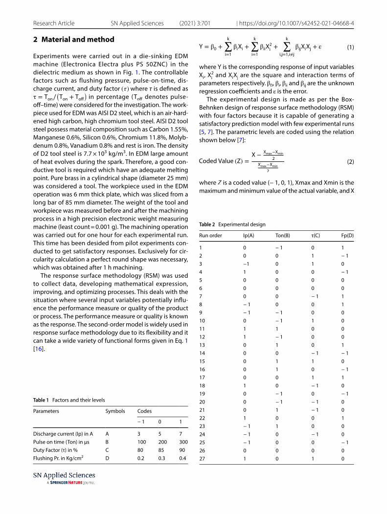
The experimental design is made as per the Box-Behnken design of response surface methodology (RSM) with four factors because it is capable of generating a satisfactory prediction model with few experimental runs [5, 7]. The parametric levels are coded using the relation shown below [7]:
where Z is a coded value (− 1, 0, 1), Xmax and Xmin is the maximum and minimum value of the actual variable, and X
(1)Y = β0 +
k∑
i=1
βiXi +
k∑
i=1
βiiX2i+
k∑
i,j=1,i≠j
βijXiXj + ε
(2)Coded Value (Z) =X −
Xmax−Xmin
2
Xmax−Xmin
2
Table 1 Factors and their levels
Parameters Symbols Codes
− 1 0 1
Discharge current (Ip) in A A 3 5 7Pulse on time (Ton) in µs B 100 200 300Duty Factor (τ) in % C 80 85 90Flushing Pr. in Kg/cm2 D 0.2 0.3 0.4
SN Applied Sciences (2021) 3:701 | https://doi.org/10.1007/s42452-021-04668-4 Research Article
is the actual value of the corresponding variable. The value of parameter setting in coded form are shown in Table 1.
In the Box-Behnken experimental design 2 k = 16 fac-torial points (k = 4 is the number of process parameters), eight axial points, and three center points are considered. The layout of the experimental design is shown in Table 2.
Each experiment was run for one hour and the responses are calculated as follows [18]:
i.
ii. where ΔWW is the weight of material removed from the workpiece during machining and ΔWt is the weight of material removed from the tool during machining, �W and �t are densities of workpiece and tool respectively, T is the time of machining.
iii. Roughness was measured by a portable stylus type profilometer (Taylor Hobson, Surtronic 3 + talysurf ).
iv. Circularity was measured as the ratio of minimum to maximum Feret’s diameter. Where Feret’s diameter is the shortest distance between the parallel tangents drown on two opposite sides of the hole as shown in Fig. 2 [36]. The machined area was magnified (45-X magnification) by Samsung camera attached to a RADIAL INSTRUMENT microscope and Feret’s diam-eter was measured by drawing tangents as shown in Fig. 2.
(3)MRR =1000 × ΔWW
ρW × Tmm3∕min
(4)TWR =1000 × ΔWt
ρW × Tmm3∕min
3 Methodology
This paper presents a structured and generic methodol-ogy that includes both RSM as well as AI tools to minimize the uncertainty in decision-making. The investigation is made to convert multiple responses into a single perfor-mance characteristic index via a neuro-fuzzy based model. The relationship between MPCI and process parameters is developed through a statistically valid regression equa-tion. PSO is used to find out the best parameter setting using the developed process model. Assume n experi-ments were conducted utilizing RSM and responses obtained as MRR, TWR, Ra , and Circularity. The responses were divided into three main categories: the smaller-the better (STB), the nominal-the-best (NTB), and the larger the-better (LTB) responses. In practice, all the responses are not of the same category. Therefore, characteristic responses are converted to respective S/N ratios as fol-lows [37]:
The larger-the-best performance characteristic can be expressed as:
The smaller-the-best performance characteristic can be expressed as:
where Yi is the ith experimental data of response.All the S/N ratio responses
(Xij
) are normalized to obtain
a normalized response (Zij) so that they lie in the range,
0 ≤ Zij ≤ 1 . Normalization is carried out to avoid the scaling effect and minimize the variation of the S/N ratio obtained at different scales. For responses of smaller-the-better type and larger-the-better normalization is carried out using Eq. 5 [16].
e fuzzy logic process can be applied effectively, where the input–output have nonlinear relation. The fuzzy logic can classify the input and output data sets broadly into different fuzzy classes. The membership function can be assign to crisp data sets by inference, intuition and AI tools. The common data clustering techniques are hard c mean clustering (HCM), and fuzzy c-mean clustering (FCM). HCM
Research Article SN Applied Sciences (2021) 3:701 | https://doi.org/10.1007/s42452-021-04668-4
is used to assign a single membership in anyone, and only one, data cluster [22, 28]. However, the FCM extends crisp classification idea into a fuzzy classification notion. Therefore, the membership to the various data points can be assigned in each fuzzy set (fuzzy class, fuzzy cluster), along with the restriction (analogous to the crisp classifi-cation) that the sum of all membership values for a single data point in all of the classes has to be unity. FCM mini-mizes the membership function assigning uncertainty of crisp data into different fuzzy classes. The data points are grouped into c clusters by calculating the fuzzy partition matrix using fuzzy c-means algorithm. Therefore, the cent-ers (centroids) are clustered, that minimize dissimilarity function Jm [37].
The membership value for kth data point in the ith cluster is μik , m’ is the weighting parameter varying in the range [1, ∞], the matrix of fuzzy partition is U, viz cluster center matrix, and similarity matrix is d, given in Eq. 7. Uti-lizing the Euclidean distance measure to characterize the similarity, the elements of d are calculated by [37]:
where m is the number of features, xk is kth data point and vi is the centroid of ith cluster that can be presented by
(for i = 1 to c) and the cluster centers are calculated using the following formulation [37]
where x is a fuzzy variable describing data point. In essence, fuzzy partitioning is performed through an itera-tive optimization utilizing the following formulation:
It should be noted that sum of membership values fora cluster must be equal to 1 i.e.
(6)
Jm (U∗, v∗) = min[Jm (U , v)
]= min
[n∑
k=1
c∑
i=1
(�ik
)m�(dik
)2]
(7)dik = d(xk − vi
)= ‖‖xk − vi
‖‖ =
√√√√
m∑
j=1
(xkj − vij
)2(for i = 1 to c and k = 1 to n)
Vi ={Vi1, Vi2, … ., Vim
}
(8)vij =
∑n
k=1�m�
ikxkj
∑n
k=1�m�
ik
(for i = 1 to c and j = 1 to m)
(9)uik(s + 1) =
1�∑c
j=1
�dik (s)
djk (s)
� 2
m�−1
�
∑
i∈Ik
μik = 1
Finally, the best available solution within a predefined accuracy criterion is determined by:
where ε is error level for the termination of iteration
which varies between 0 and 1. In detail, this iterative pro-cedure converges to a local minimum of Jm . Algorithmi-cally, fuzzy c-means methodology can be explained by a flowchart given in Fig. 3.
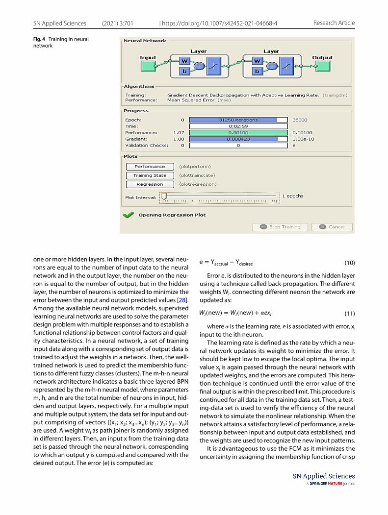
The membership function is repeatedly updated when the system parameters continuously change in a non-deterministic fashion. A neural network (NN) is used for these types of systems, as it is capable of modifying itself by adapting the weights. Neural network learns by modify-ing its structure rather than adding new rules to its knowl-edge base [26]. In this work, a backpropagation neural network (BPN) is implemented in output data to generate the fuzzy membership function for fuzzy classes. The rela-tionship between the training data and the corresponding membership values (from FCM) is established by simulat-ing it in BPN. The membership value is assigned to each training-data in different fuzzy classes. The performance of NN is checked by testing-data. After training of NN, it is used to determine the membership values of any input data in the different fuzzy classes (Fig. 4).
A neural network use models that simulate the work-ing model of the neurons in the human brain. It consists of two fixed layers an input layer and an output layer and
‖‖‖U(r+1) − U(r)‖‖
‖≤∈
s = 0
Initialize U matrix randomly
yes
Compute v matrix (Eq. 7)
U(s+1)-U(s) < ε
Modify U matrix (Eq. 8)
Calculate d matrix (Eq. 6)
Iteration is terminated
nos = s+1
Fig. 3 Flow Chart for fuzzy c-mean clustering
Vol.:(0123456789)
SN Applied Sciences (2021) 3:701 | https://doi.org/10.1007/s42452-021-04668-4 Research Article
one or more hidden layers. In the input layer, several neu-rons are equal to the number of input data to the neural network and in the output layer, the number on the neu-ron is equal to the number of output, but in the hidden layer, the number of neurons is optimized to minimize the error between the input and output predicted values [28]. Among the available neural network models, supervised learning neural networks are used to solve the parameter design problem with multiple responses and to establish a functional relationship between control factors and qual-ity characteristics. In a neural network, a set of training input data along with a corresponding set of output data is trained to adjust the weights in a network. Then, the well-trained network is used to predict the membership func-tions to different fuzzy classes (clusters). The m-h-n neural network architecture indicates a basic three layered BPN represented by the m-h-n neural model, where parameters m, h, and n are the total number of neurons in input, hid-den and output layers, respectively. For a multiple input and multiple output system, the data set for input and out-put comprising of vectors {(x1; x2; x3...xn); (y1; y2; y3.. yn)} are used. A weight wi as path joiner is randomly assigned in different layers. Then, an input x from the training data set is passed through the neural network, corresponding to which an output y is computed and compared with the desired output. The error (e) is computed as:
Error e . is distributed to the neurons in the hidden layer using a technique called back-propagation. The different weights Wi . connecting different neonsn the network are updated as:
where � is the learning rate, e is associated with error, xi input to the ith neuron.
The learning rate is defined as the rate by which a neu-ral network updates its weight to minimize the error. It should be kept low to escape the local optima. The input value xi is again passed through the neural network with updated weights, and the errors are computed. This itera-tion technique is continued until the error value of the final output is within the prescribed limit. This procedure is continued for all data in the training data set. Then, a test-ing-data set is used to verify the efficiency of the neural network to simulate the nonlinear relationship. When the network attains a satisfactory level of performance, a rela-tionship between input and output data established, and the weights are used to recognize the new input patterns.
It is advantageous to use the FCM as it minimizes the uncertainty in assigning the membership function of crisp
(10)e = Yacctual − Ydesired
(11)Wi(new) = Wi(new) + �exi
Fig. 4 Training in neural network
Vol:.(1234567890)
Research Article SN Applied Sciences (2021) 3:701 | https://doi.org/10.1007/s42452-021-04668-4
data into various fuzzy classes. The BPN as training data set used each data and its corresponding membership values from FCM. The membership values are assigned to training data by simulating input data and membership values in different fuzzy classes. Then the membership values are determined for input data. The defuzzification method is the conversion of a fuzzy quantity to a specific quantity. Among the various methods, the COA method is used for defuzzifying the fuzzy output function into crisp data [38, 39]. In this method, the fuzzy output μA(y) . transform into a crisp value y . It is given by the expression as in Eq. 12 [37]
4 Particle swarm optimization
PSO is a stochastic optimization algorithm that was origi-nally motivated by the thinking model of an individual of the social organism such as birds, fish, etc. by Kennedy and Eberhart [15]. The PSO has particles driven from a natural group with communications based on evolution-ary computation and it combines self-experiences with social experiences. Here a contestant is considered as a particle and the objective is to get a global optimum. In PSO algorithm uses some flying particles from the search area as well as the movement towards a promising area. The flying particle is compared with changing solutions and the search area is compared with current and possi-ble solutions. After each iteration, the particles update its position to a goal (fitness), and local neighborhood parti-cles share memories of their “best” positions. The particle velocities and their subsequent positions are adjusted by these memories [32, 40]. In the standard PSO with ‘Z’ parti-cles in the D dimensional search space, the potential solu-tion can be represented by the particle’s position vector Xi(t) . The position Xi(t) , of the ith particle is adjusted by a stochastic velocity Vi(t) . Thus, the particle moves according to the following equation [32]:
where i = 1, 2, ….., N, pbesti (t) is the best solution that par-ticle i s obtained until iteration generation t, and gbesti(t) is the best solution obtained from pbesti(t) in the whole swarm at iteration t. w is inertia weight, C1 is the cognition learning factor and C2 is the social learning factor; r1 and r2 are the random numbers uniformly distributed in (0,1) [29,
(12)y =∫ �A ⋅ y dy
∫ �A(y) dy
(13)Vi(t) = WXi(t) + C1r1
(pbesti(t) − Xi(t)
)+ C1r1
(gbestj(t) − Xi(t)
)
(14)Xi(t + 1) = Xi(t) + Vi(t + 1)
30, 41]. The procedure for implementing the PSO is given by the following steps.
Step 1: Initialization of swarm positions and veloci-ties: A uniform probability distribution function is used in the D dimensional problem space to initialize a population (array) of particles with random positions and velocities.
Step 2: Evaluation of fitness of particle: The fitness function is maximized in evaluation of fitness value of each particle.
Step 3: Comparison to ����� (personal best): Each particle’s fitness is compared with the particle’s pbest . If the obtained current value is superior than the exsisting pbest , then the pbest value is replaced with the current value and the pbest location is updated by current location in a D-dimensional space.
Step 4: Comparison to ����� (global best): The fitness is compared with the previous pbest population. If the obtained current value is superior than gbest , then gbest is resetted to the array index and value of current particle.
Step 5: Updating of each particle’s velocity and position: Modify the velocity Vi , and particle’s position, Xi , according to Eq. 13 and Eq. 14 respectively.
5 Result and discussion
The experiments have been conducted as per the experi-mental plan shown in Table 2. Four responses are meas-ured as explained in Sect. 3. Out of four responses, two responses such as MRR and circularity are to be maximized whereas two responses EWR and Ra are to be minimized. Since the responses are contradicting in nature, they were converted to S/N ratio to make them into the same char-acteristic nature as explained in Sect. 4. The S/N ratios of responses are shown in Table 3. The S/N ratios exhibit large variation as evident from Table 3. Therefore, they were nor-malized using Eq. 5 and normalized values are presented in Table 3. Then, a supervised learning BPN is modeled to find the membership function. These normalized data sets have been clustered by using fuzzy clustering into four fuzzy classes R1 , R2 , R3 , and R4 . There are twenty seven num-bers of data sets as listed in Table 3, each of them compris-ing four responses or coordinates. The matrix U as shown in Table 4, gives the value of the membership of each data into four fuzzy classes. This occurs when the objective function of fuzzy c-means (FCM) is converged after thirty four iterations. The numbers for each cluster indicate the experiment number or run number.
SN Applied Sciences (2021) 3:701 | https://doi.org/10.1007/s42452-021-04668-4 Research Article
Since four input and four output parameters were included in the experiment, similar numbers of neurons in input layer and output later have been chosen. The hidden layer neurons were determined by various Backpropaga-tion Neural Networks (BPN) model. The models have been chosen to achieve performance error equal to 0.001. Six BPN models 4–5–4, 4–6–4, 4–7–4, 4–8–4, 4–9–4, 4–10–4 have been selected. Data set 1–18 are selected as train-ing data and data set 19–27 have been used to test the performance of the selected neural network. Finally, BPN architecture 4–8-4 showed minimum root mean square error (RMSE). Learning and momentum parameters were set at 0.12 and 0.50. The number of epochs the BPN was run was 31,250. In spite of higher number of iterations to converge at a final value, low learning rate was used to ensure the neural network to escape from local optima.
Initially quasi-random weights have been assigned for four layers. Thereafter, the data serial number 1 with input co-ordinates X1 = 0.125995 0, X2 = 0.698949 , X3 = 1 , and
X4 = 0.4145741 corresponding to the output membership 0.0546 ( R1 ), 0.1098 ( R2 ), 0.0028 ( R3 ) and 0.8328 ( R4 ) was entered. The output of the network was computed and compared with the desired output to calculate the error. The initial assigned weights were repeatedly adjusted to minimize the error, until the target achieved to 0.001 as shown in Fig. 5. Similarly, data set (2–18) are entered and weights are readjusted. The data set (19–27) are used to test the performance of the network. It has been observed that after 31,250 iterations, the network achieves a sat-isfactory level of error as shown in Fig. 4. The obtained adjusted membership values are shown in Table 5.
Regression curves are plotted as shown in Fig. 5 and Fig. 6, between actual membership function and pre-dicted membership function via neuro-fuzzy model for training data and testing data respectively. Figure 5 and 6 shows that the data are well fitted because a high degree of correlation coefficient (R) = 0.99897 for training and (R) = 0.99854 for testing data. This indicate that the data
Table 3 Signal-to-noise ratio and Normalized value
Sl. no IP(A) Ton(µs) τ(%) fP Signal-to-noise ratio Normalized value
Research Article SN Applied Sciences (2021) 3:701 | https://doi.org/10.1007/s42452-021-04668-4
are well trained and can be predicted. Figure 6 shows the membership functions for output predicted by neural net-work. After getting fuzzified value, it is needed to defuzzify them to get a crisp value containing the combined quality
characteristic which can be used as higher the best crite-ria. This has done by center of area (COA) method. These defuzzified data are called MPCI, listed in Table 6.
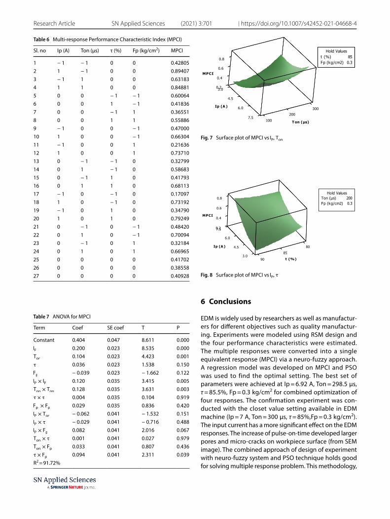
The MPCI values are considered as single response and analysis of variance shown in Table 7, it is observed that the factors IP , Ton , and τ and square terms IP × IP and Ton × Ton , and interaction τ × Fp are statistically signifi-cant. The highest effect was observed in IP followed by Ton , Ton × Ton , IP × IP , τ × Fp . IP has highest effect because it directly contribute to the heat generation. As IP increases the spark become stronger and more erosion arise. The process model is obtained by regression analysis as given in Eq. 15 and coefficient of determination (R2) was found to be 91.72%.
Figure 7 shows the response surface for MPCI in relation to the process parameters of discharge current and pulse on time. It can be seen from the figure that the MPCI tends to increase rapidly with an increase in peak current for any value of pulse-on-time. Figure 7 also indicates that maxi-mum MPCI value is obtained at high peak current (7 A) and high pulse on time (300 μs). This is due to their principal control over the input spark energy. As the discharge cur-rent increases, it generates a strong spark which produces a higher temperature as a result of more material was eroded from the work piece. Figure 8 shows the response surface
Fig. 5 a Regression plot for training data b Regression plot for testing data
Vol.:(0123456789)
SN Applied Sciences (2021) 3:701 | https://doi.org/10.1007/s42452-021-04668-4 Research Article
for MPCI in relation to the process parameters of discharge current and duty factor. It can be observed from the figure that MPCI increases as IP increases for any value of τ.
PSO technique was used to determine the optimal parameter setting using the model shown in Eq. 15. The PSO algorithm was run for 100 iterations but converged at 59 iterations as shown in Fig. 9. The optimal value of MPCI is obtained as 0.946 at parametric values of IP=0.96, Ton=0.99, τ = 0.11, Fp=0.105 in coded form. These values are decoded using Eq. 2 and actual values of factors are found to be IP=6.92 A, Ton=298.5 µs, τ = 85.5 %, Fp = 0.3 kg/cm2 respec-tively. The results obtained for peak current and pulse on time can be validated by comparing it with results obtained in similar work presented in [13], and [15]. The conformation experiment was conducted with the closet value setting available in EDM machine ( IP = 7 A, Ton=300 µs, τ = 85 %, Fp = 0.3 kg/cm2). The corresponding MRR was obtained as highest value 7.037 (mm3/min), TWR = 3.265 (mm3/min), Ra = 0.855 µm and circularity = 7.59. These values are the optimal responses in the conducted experiments.
The machined surface of experiment numbers 22 ( IP = 5 A, Ton = 300 µs, τ = 80%, fP=0.3 kg/cm2) and 23 ( IP = 5A, Ton = 100μs , τ = 90% , fP=0.3 kg/cm2) was ana-lyzed under a scanning electron microscope at 1000 magnification (Model JEOL JSM-6480LV). Figure 10 shows pores and micro-cracks for experiment number 22 and Fig. 11 shows a similar observation for experiment num-ber 23. It can be observed that a few larger pores and small number of micro-cracks are present in Fig. 10. In Fig. 11, more number of small pores and more number of micro cracks are present. The increase of pulse-on-time establish more heat between tool and workpiece. The higher ther-mal gradient may give rise to high residual stress causing more pores and larger cracks.
Research Article SN Applied Sciences (2021) 3:701 | https://doi.org/10.1007/s42452-021-04668-4
6 Conclusions
EDM is widely used by researchers as well as manufactur-ers for different objectives such as quality manufactur-ing. Experiments were modeled using RSM design and the four performance characteristics were estimated. The multiple responses were converted into a single equivalent response (MPCI) via a neuro-fuzzy approach. A regression model was developed on MPCI and PSO was used to find the optimal setting. The best set of parameters were achieved at Ip = 6.92 A, Ton = 298.5 μs, τ = 85.5%, Fp = 0.3 kg/cm2 for combined optimization of four responses. The confirmation experiment was con-ducted with the closet value setting available in EDM machine (Ip = 7 A, Ton = 300 µs, τ = 85%,Fp = 0.3 kg/cm2). The input current has a more significant effect on the EDM responses. The increase of pulse-on-time developed larger pores and micro-cracks on workpiece surface (from SEM image). The combined approach of design of experiment with neuro-fuzzy system and PSO technique holds good for solving multiple response problem. This methodology,
Table 6 Multi-response Performance Characteristic Index (MPCI)
SN Applied Sciences (2021) 3:701 | https://doi.org/10.1007/s42452-021-04668-4 Research Article
being simple and robust, can be applied in other situa-tions where multiple conflicting objectives are desired to be optimized simultaneously.
Declarations
Conflict of interest The authors declare that they have no conflict of interest.
Open Access This article is licensed under a Creative Commons Attri-bution 4.0 International License, which permits use, sharing, adap-tation, distribution and reproduction in any medium or format, as long as you give appropriate credit to the original author(s) and the source, provide a link to the Creative Commons licence, and indicate if changes were made. The images or other third party material in this article are included in the article’s Creative Commons licence, unless indicated otherwise in a credit line to the material. If material is not included in the article’s Creative Commons licence and your intended use is not permitted by statutory regulation or exceeds the permitted use, you will need to obtain permission directly from the copyright holder. To view a copy of this licence, visit http:// creat iveco mmons. org/ licen ses/ by/4. 0/.
References
1. Sanchez JA, Rodil JL, Herrero A, Lacalle LNL, Lamikiz A (2007) On the influence of cutting speed limitation on the accuracy of wire-EDM corner-cutting. J Mater Process Technol 182:574–579
2. Ramakrishnan R, Karunamoorthy L (2006) Multi response opti-mization of wire EDM operations using robust design of experi-ments. Int J Adv Manuf Technol 29:105–112
3. Kumara S, Singh R, Singh TP, Sethi BL (2009) Surface modifica-tion by electrical discharge machining: a review. J Mater Process Technol 209:3675–3687
4. Box GEP, Hunter WG, Hunter JS (1978) Statistics for experiment-ers. Wiley, New York
5. Montgomery DC (1991) Design and analysis of experiments. Wiley, New York
6. Ghafari S, Aziz AH, Isa MH, Zinatizadeh AA (2009) Application of response surface methodology (RSM) to optimize coagula-tion–flocculation treatment of leachate using poly-aluminum chloride (PAC) and alum. J Hazard Mater 163:650–656
7. Kansal HK, Singh S, Kumara P (2005) Parametric optimization of powder mixed electrical discharge machining by response surface methodology. J Mater Process Technol 169(3):427–436
8. Antony J, Bardhan AR, Kumar M, Tiwari MK (2006) Multiple response optimization using Taguchi methodology and neuro-fuzzy based model. J Manuf Technol Manag 17(7):908–925
9. Tong LI, Su CT (1997) Optimizing multi-responses problem in the Taguchi method by fuzzy attribute decision making. Qual Reliab Eng Int 13:25–34
10. Tarang YS, Yang WH, Juang SC (2000) The use of fuzzy logic in the taguchi method for the optimization of the submerged arc welding process. Int J Adv Manuf Technol 16(9):688–694
11. Eberhart R, Kennedy I (1995) A new optimizer using particle swarm theory. Sixth International Symposium on Micro Machine and Human Science, Nagoya Municipal Industrial Research Insti-tute, Japan 39–43
12. Lee SH, Li XP (2001) Study of effect of machining parameters on the machining characteristics in electric discharge machining of tungsten carbide. J Mater Process Technol 115:334–358
0.84
0.86
0.88
0.9
0.92
0.94
0.96
0.98
1 8 15 22 29 36 43 50 57 64 71 78 85 92 99
MPC
I
Itera�on Number
Fig. 9 The convergence curve
Fig. 10 SEM micrographs showing pores and cracks for experiment number 22
Fig. 11 SEM micrographs showing pores and cracks for experiment number 22
Research Article SN Applied Sciences (2021) 3:701 | https://doi.org/10.1007/s42452-021-04668-4
13. Tebni W, Boujelbene M, Bayraktar E, Salem SB (2009) Parametric approach model for determining electrical discharge machining (EDM) conditions: effect of cutting parameters on the surface integrity. Arab J Sci Eng 34(1):101–114
14. Habib SS (2009) Study of the parameters in electrical discharge machining through response surface methodology approach. Appl Math Model 33(12):4397–4407
15. Singh P, Beri N, Kumar A (2010) Some studies on electric dis-charge machining of hastlealloy using powder metallurgy elec-trode. Int J Adv Manuf Technol 1:16–27
16. Pradhan MK, Biswas CK (2011) Modeling and analysis of process parameters on surface roughness in EDM of AISI D2 tool steel by RSM approach. World Academy of Sci, Eng Technol 2:814–819
17. Helmi MH, Azuddin M, Abdullah W (2007) Investigation of surface roughness and material removal rate (MRR) on tool steel using brass and copper electrode for electrical discharge grinding (EDG) process. Int J Integr Eng 1(I):31–39
18. Chattopadhyay KD, Verma S, Satsangi PS, Sharma PC (2009) Devel-opment of empirical model for different process parameters dur-ing rotary electrical discharge machining of copper–steel (EN-8) system. J Mater Process Technol 209:1454–1465
19. Abbas NM, Solomon DG, Bahari MF (2007) A review on current research trends in EDM. Int J Mach Tools Manuf 47(7–8):1214–1228
20. Keskin Y, Kalkaci HS, Kizil M (2006) An experimental study for deter-mination of effects of machining parameters on surface roughness in EDM. Int J Adv Technol 28(11–12):1118–1121
21. Wang K, Gelgele HL, Wang Y, Yuan Q, Fang M (2003) A hybrid intel-ligent method for modeling the EDM process. Int J Machine Tools Manuf 43(10):995–999
22. Su JC, Kao JY, Tarng YS (2004) Optimization of the electrical dis-charge machining process using a GA based neural networks. Int J Adv Manuf Technol 24(2):81–90
23. Liao HC (2003) Using PCR-TOPSIS to optimise Taguchi’s multi-response problem. Int J Adv Manuf Technol 22:649–655
24. Singh NK, Singh Y, Kumar S, Upadhyay R (2020) Integration of GA and neuro-fuzzy approaches for the predictive analysis of gas-assisted EDM responses. SN Appl Sci 2(1):1–4
25. Babu KN, Karthikeyan R, Punitha A (2010) An integrated ANN–PSO approach to optimize the material removal rate and surface roughness of wire cut EDM on INCONEL 750. Mater Today Proc 1(19):501–505
26. Panda DK, Bhoi RJ (2005) Artificial neural network predic-tion of material removal rate in EDM. Mater Manuf Processes 20(4):645–672
27. Yang SH, Srinivas J, Mohana S, Lee DK, Balaji S (2009) Optimiza-tion of electric discharge machining using simulated annealing. J Mater Process Technol 209(9):4471–4475
28. Somashekhar KP, Ramachandran N, Jose M (2010) Optimization of material removal rate in micro-EDM using artificial neural network and genetic algorithms. Mater Manuf Processes 25(6):467–475
29. Kennedy J, Eberhart R (1995) Particle swarm optimization. Pro-ceedings of ICNN’95 - International Conference on Neural Net-works, vol 4, Perth, WA, Australia, pp 1942–1948
30. Saffaran A, Moghaddam MA, Kolahan F (2020) Optimization of backpropagation neural network-based models in EDM process using particle swarm optimization and simulated annealing algo-rithms. J Braz Soc Mech Sci Eng 42:73
31. Tang JG, Zhang XM, Deng YL, Du YX, Chen ZY (2006) Texture decomposition with particle swarm optimization method. Com-put Mater Sci 38:395–399
32. Clerc M, Kennedy JF (2002) The particle swarm: explosion, stabil-ity and convergence in a multi-dimensional complex space. IEEE Transac Evolutionary Comput 6(1):58–73
33. Xi M, Sun J, Xu W (2008) An improved quantum-behaved particle swarm optimization algorithm with weighted mean best position. Appl Math Comput 205(2):751–759
35. Mohanty CP, Behura AK, Singh MR, Prasad BN, Kumar A, Dwivedi G, Verma P (2020) Parametric performance optimization of three sides roughened solar air heater, Energy Sources, Part A: Recovery, Utilization, and Environmental Effects
36. Biswas R, Kuar AS, Biswas SK, Mitra S (2009) Artificial neural net-work modelling of Nd:YAG laser microdrilling on titanium nitride-alumina composite. Proc Instit Mech Eng J Eng Manuf Part B 224:473–482
37. Bezdek JC (1981) Pattern recognition with fuzzy objective function algorithms. Plenum press, New York
38. Lanhai L (1998) Comparison of conventional and fuzzy land clas-sification and evaluation techniques in Oxfordshire England. Int Agric Eng J 7:1–12
39. Bojadziev G, Bojadziev M (1995) Fuzzy Sets, Fuzzy Logic and Appli-cations. World Scientific, London
40. Subbaiah KV, Mouli KVV, Srinivas JC (2005) Particles swarm opti-mization for production planning problems. J Decision Math Sci 10:101–112
41. Wang X, Sun J, Xu W (2009) A parallel QPSO algorithm using neighborhood topology model. World Cong Comput Sci Inf Eng 4:831–835
42. Phate M, Toney S, Phate V (2020) Modelling and investigating the impact of EDM parameters on surface roughness in EDM of Al/Cu/Ni Alloy. Aust J Mech Eng 5:1–4
43. Saffaran A, Azadi Moghaddam M, Kolahan F (2020) Optimization of backpropagation neural network-based models in EDM process using particle swarm optimization and simulated annealing algo-rithms. J Braz Soc Mech Sci Eng 42:73
44. Muthuramalingam T, Saravanakumar D, Babu LG (2020) Experi-mental investigation of white layer thickness on EDM processed silicon steel using ANFIS approach. SILICON 12:1905–1911
45. Sakthivel G, Saravanakumar D, Muthuramalingam T (2017) Appli-cation of failure mode and effect analysis in manufacturing indus-try - an integrated approach with FAHP-fuzzy TOPSIS and FAHP-fuzzy VIKOR. Int J Product Quality Manag 24:398–423
46. Shankar C, Protim DP (2019) Fuzzy modeling and parametric analy-sis of non-traditional machining processes. Manag Product Eng Rev 10:111–123
47. Moghaddam MA, Kolahan F (2019) Modeling and optimization of the electrical discharge machining process based on a combined artificial neural network and particle swarm optimization algo-rithm. Int J Sci Technol 27:1206–1217
48. Chakraborty S, Bhattacharyya B, Diyaley S (2018) Applications of optimization techniques for parametric analysis of non-traditional machining processes: a review. Manag Sci Lett 9:467–494
49. Marichamy S, Saravanan M, Ravichandran M (2016) Paramet-ric optimization of EDM process on α–β brass using Taguchi approach. Russ J Non-ferrous Metals 57:586–598
50. Marichamy S, Saravanan M, Ravichandran M, Veerappan G (2016) Parametric optimization of electrical discharge machining pro-cess on α–β brass using grey relational analysis. J Mater Res 31:2531–2537
51. Marichamy S, Stalin B, Ravichandran M, Sudha GT (2020) Optimiza-tion of machining parameters of EDM for α-β brass using response surface methodology. Mater Today: Proc 24:1400–1409
Publisher’s Note Springer Nature remains neutral with regard to jurisdictional claims in published maps and institutional affiliations.