118
USER’S MANUAL FX 2N -64DP-M Profibus-DP Master Block

USER’S MANUAL
FX2 N-64DP-M Prof ibus-DP Master Block
Foreword
• This manual contains text, diagrams and explanations which will guide the reader in the cor-rect installation and operation of the FX2N-64DP-M Profibus-DP Master Block. It should beread and understood before attempting to install or use the unit.
• Further information can be found in the FX2N Series Hardware Manual, FX Series Program-ming Manual, MELSEC ProfiMap Configuration System for Open Networks Software Man-ual and manual of Profibus-DP slave units.
• If in doubt at any stage of the installation of FX2N-64DP-M Profibus-DP Master Block alwaysconsult a professional electrical engineer who is qualified and trained to the local andnational standards which apply to the installation site.
• If in doubt about the operation or use of FX2N-64DP-M Profibus-DP Master Block pleaseconsult the nearest Mitsubishi Electric distributor.
• This manual is subject to change without notice.
FX2N-64DP-M Profibus-DP Master Block

i
FX2N-64DP-M PROFIBUS-DPMaster Block
USER’S MANUAL
Manual number : JY992D88001
Manual revision : B
Date :March 2001
FX2N-64DP-M Profibus-DP Master Block

FX2N-64DP-M Profibus-DP Master Block
ii

FAX BACK
Mitsubishi has a world wide reputation for its efforts in continually developing and pushing backthe frontiers of industrial automation. What is sometimes overlooked by the user is the careand attention to detail that is taken with the documentation. However,to continue this processof improvement, the comments of the Mitsubishi users are always welcomed. This page hasbeen designed for you,the reader,to fill in your comments and fax them back to us. We lookforward to hearing from you.
Fax numbers: Your name....................................................
Mitsubishi Electric.... .....................................................................
America (01) 847-478-2283 Your company ..............................................
Australia (02) 638 -7072 .....................................................................
Germany (0 21 02) 4 86-1 12 Your location: ...............................................
South Africa (0 27) 11 444-0223 .....................................................................
United Kingdom (01707) 278-695
Please tick the box of your choice
What condition did the manual arrive in? Good Minor damage Unusable
Will you be using a folder to store the manual? Yes No
What do you think to the manual presentation? Tidy Unfriendly
Are the explanations understandable? Yes Not too bad Unusable
Which explanation was most difficult to understand: ......................................................................................................................................................................................................................
Are there any diagrams which are not clear? Yes No
If so,which:..................................................................................................................................
What do you think to the manual layout? Good Not too bad Unhelpful
If there one thing you would like to see improved,what is it?..............................................................................................................................................................................................................................................................................................................................................................
Could you find the information you required easily using the index and/or the contents,if possi-ble please identify your experience: ...........................................................................................................................................................................................................................................................................................................................................................................................................................................................................................................................................................................................................................................................................................................
Do you have any comments in general about the Mitsubishi manuals? .....................................................................................................................................................................................................................................................................................................................................................................................................................................................................................................................................................................................................................................................
Thank you for taking the time to fill out this questionnaire. We hope you found both the productand this manual easy to use.
FX2N-64DP-M Profibus-DP Master Block
iii

FX2N-64DP-M Profibus-DP Master Block
iv
FX2N-64DP-M Profibus-DP Master Block
Guidelines for the Safety of the User and Protection of the FX2N-64DP-MProfibus-DP Master Block
This manual provides information for the use of the FX2N-64DP-M Profibus-DP Master Block.The manual has been written to be used by trained and competent personnel. The definition ofsuch a person or persons is as follows;
a) Any engineer who is responsible for the planning, design and construction of automaticequipment using the product associated with this manual should be of a competentnature, trained and qualified to the local and national standards required to fulfill thatrole. These engineers should be fully aware of all aspects of safety with regards toautomated equipment.
b) Any commissioning or service engineer must be of a competent nature, trained andqualified to the local and national standards required to fulfill that job. These engineersshould also be trained in the use and maintenance of the completed product. Thisincludes being completely familiar with all associated documentation for the saidproduct. All maintenance should be carried out in accordance with established safetypractices.
c) All operators of the completed equipment should be trained to use that product in a safeand co-ordinated manner in compliance to established safety practices. The operatorsshould also be familiar with documentation which is connected with the actual operationof the completed equipment.
Note : Note: the term ‘completed equipment’ refers to a third party constructed device whichcontains or uses the product associated with this manual.
Notes on the Symbols Used in this Manual
At various times through out this manual certain symbols will be used to highlight points ofinformation which are intended to ensure the users personal safety and protect the integrity ofequipment. Whenever any of the following symbols are encountered its associated note mustbe read and understood. Each of the symbols used will now be listed with a brief description ofits meaning.
Hardware Warnings
1) Indicates that the identified danger WILL cause physical and property damage.
2) Indicates that the identified danger could POSSIBLY cause physical and propertydamage.
3) Indicates a point of further interest or further explanation.
Software Warnings
4) Indicates special care must be taken when using this element of software.
5) Indicates a special point which the user of the associate software element shouldbe aware of.
6) Indicates a point of interest or further explanation.
v
FX2N-64DP-M Profibus-DP Master Block
• Under no circumstances will Mitsubishi Electric be liable responsible for any consequentialdamage that may arise as a result of the installation or use of this equipment.
• All examples and diagrams shown in this manual are intended only as an aid tounderstanding the text, not to guarantee operation. Mitsubishi Electric will accept noresponsibility for actual use of the product based on these illustrative examples.
• Owing to the very great variety in possible application of this equipment, you must satisfyyourself as to its suitability for your specific application.
vi
FX2N-64DP-M Profibus-DP Master Block
Table of Contents
Guideline of Safety...............................................................................v
1. Introduction............................................................................................1-11.1 Features of the 64DP-M ...................................................................................... 1-11.2 External Dimensions and Each part Name.......................................................... 1-2
1.2.1 Pin configuration of Profibus-DP Connector.............................................................. 1-31.3 System Configuration .......................................................................................... 1-4
1.3.1 Applicable Profibus-DP Network ............................................................................... 1-41.3.2 Applicable Programmable Controller......................................................................... 1-9
1.4 Communication Time........................................................................................... 1-91.4.1 Polling Cycle Time................................................................................................... 1-10
2. Wiring and Mounting .............................................................................2-12.1 Mounting.............................................................................................................. 2-1
2.1.1 Arrangements ............................................................................................................ 2-12.1.2 Mounting.................................................................................................................... 2-1
2.2 Wiring .................................................................................................................. 2-22.2.1 Caution ...................................................................................................................... 2-22.2.2 Wiring ........................................................................................................................ 2-32.2.3 Wiring of Power Supply ............................................................................................. 2-32.2.4 Wiring of Profibus-DP................................................................................................ 2-42.2.5 Terminating resistor................................................................................................... 2-4
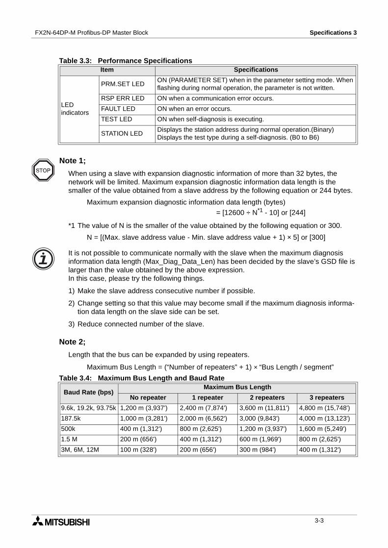
3. Specifications ........................................................................................3-13.1 General Specifications......................................................................................... 3-13.2 Power Supply Specifications ............................................................................... 3-13.3 Performance Specifications................................................................................. 3-2
vii
FX2N-64DP-M Profibus-DP Master Block
4. Allocation of Buffer Memories (BFMs)...................................................4-14.1 Buffer Memories (BFM) Lists ............................................................................... 4-14.2 Communication Status Flags <BFM #0, BFM #1> (Read Only) .......................... 4-34.3 Communication Control Flags <BFM #2> (Read / Write) .................................. 4-104.4 Communication Stop Timer Setting <BFM #9> (Read / Write).......................... 4-124.5 Slave Data Consistency Mode <BFM #10 ~ #22>............................................. 4-13
4.5.1 Slave Data Consistency Mode Process .................................................................. 4-144.5.2 Output Data Send Request Flags <BFM #11 ~ #14> (Read / Write) ...................... 4-154.5.3 Output Data Sending End Flags <BFM #15 ~ #18> (Read Only) ........................... 4-154.5.4 Output Data Send Error Flags <BFM #19 ~ #22> (Read / Write)............................ 4-16
4.6 Master Reset <BFM #27> (Read / Write) .......................................................... 4-184.7 Initial Data Set <BFM #28> (Read / Write) ........................................................ 4-184.8 Master Status <BFM #29> (Read Only) ............................................................ 4-194.9 Module ID code <BFM #30> (Read Only) ......................................................... 4-194.10 Number of Used Input Byte <BFM #37> (Read Only) ....................................... 4-194.11 Number of Allocated Slave <BFM #38> (Read Only) ........................................ 4-194.12 Operation Service Mode <BFM #39> (Read Only)............................................ 4-194.13 Input Slave State <BFM #40 ~ #43> (Read Only) ............................................. 4-204.14 Output Slave State <BFM #44 ~ #47> (Read Only) .......................................... 4-204.15 Input Data Area <BFM #100 ~ #1059> (Read Only) ......................................... 4-21
4.15.1 Normal Service Mode <Mode Switch: 0> ................................................................ 4-214.15.2 Extended Service Mode <Mode Switch: E> ............................................................ 4-23
4.16 Output Data Area <BFM #1060 ~ #2019> (Read / Write) ................................. 4-244.16.1 Normal Service Mode <Mode Switch: 0> ................................................................ 4-244.16.2 Extended Service Mode <Mode Switch: E> ............................................................ 4-26
4.17 Address Information Area <BFM #2020 ~ #2139> (Read Only)........................ 4-274.18 Communication Trouble Area <BFM #2140 ~ #2179> (Read Only).................. 4-29
4.18.1 Fixed Type and Ring Type methods ....................................................................... 4-304.18.2 Error codes .............................................................................................................. 4-31
4.19 Expansion Communication Trouble Area <BFM #2196 ~ #2210> (Read Only) 4-344.19.1 BFM #2196.............................................................................................................. 4-354.19.2 BFM #2197.............................................................................................................. 4-364.19.3 BFM #2198 ~ #2210................................................................................................ 4-364.19.4 Example of the Expansion Communication Trouble Area ....................................... 4-40
4.20 Slave Diagnostic Status Cancel <BFM #2180> (Read / Write) ......................... 4-414.21 Global Control Area <BFM #2181> (Read / Write) ............................................ 4-424.22 Information Dwell Time Setting <BFM #2184> (Read / Write)........................... 4-434.23 Slave Status Area <BFM #2212 ~ #2216> (Read Only).................................... 4-434.24 Input / Output Start Address Area <BFM #2228 ~ #2347>
(Extended Service Mode Only) <Read Only> ................................................... 4-44
5. Global Control .......................................................................................5-15.1 SYNC and UNSYNC Global Control ................................................................... 5-15.2 FREEZE and UNFREEZE Global Control ........................................................... 5-15.3 Global Control Service Process........................................................................... 5-2
6. Mode and Displayed Station Address ...................................................6-16.1 Mode.................................................................................................................... 6-1
6.1.1 Mode Setting Switch.................................................................................................. 6-16.2 Displayed Station Address .................................................................................. 6-2
viii
FX2N-64DP-M Profibus-DP Master Block
7. Setting Parameters and Configuration ..................................................7-17.1 Master Parameter ................................................................................................ 7-27.2 Bus Parameter..................................................................................................... 7-37.3 Network Configuration ......................................................................................... 7-4
8. Example Program..................................................................................8-18.1 System Configuration .......................................................................................... 8-18.2 Contents of Operation ......................................................................................... 8-18.3 Parameter Setting................................................................................................ 8-28.4 Example Program.............................................................................................. 8-11
9. Diagnostics............................................................................................9-19.1 Preliminary Checks.............................................................................................. 9-19.2 Check the Status of the LEDs for the 64DP-M .................................................... 9-29.3 Self Diagnostic of the 64DP-M ............................................................................ 9-49.4 Diagnostic Information and Error Code ............................................................... 9-4
Appendix A:Further Information Manual List ............................................................... A-1
ix

FX2N-64DP-M Profibus-DP Master Block
x

Introduction 1FX2N-64DP-M Profibus-DP Master Block
1. Introduction
1.1 Features of the 64DP-M
The FX2N-64DP-M Profibus-DP Master Block (hereafter called “64DP-M”) is a “Class 1” masterfor the Profibus-DP network (hereafter called “DP-network”). The FX2N series programmablecontroller by connecting 64DP-M can read input data from the Profibus-DP slave (hereaftercalled “DP-slave”), and write output data to the DP-slave.
• Controlled maximum slaves:A 64DP-M can control a maximum of 60 slaves using repeaters on the DP-network.For system configuration of the DP-network, refer to section 1.3.
• Configuration setting:Configuration of the 64DP-M can be set easily by MELSEC ProfiMap configuration software(V3.00 or more). For MELSEC ProfiMap configuration software (hereafter called “ProfiMap),refer to MELSEC ProfiMap Configuration System for Open Networks Software Manual. Forchoosing module type, refer to Appendix B.
• Communication:The 64DP-M supports 9.6k, 19.2k, 93.75k, 187.5k, 500k, 1,500k, 3M, 6M and 12Mbps.The 64DP-M can be connected to a Profibus-DP network by a standard 9-pin D-SUBconnector and shielded twisted pair cable complying with EN50170. See chapter 2.
• Global control:The 64DP-M supports Sync global control, Unsync global control, Freeze global control andUnfreeze global control.
1-1
FX2N-64DP-M Profibus-DP Master Block Introduction 1
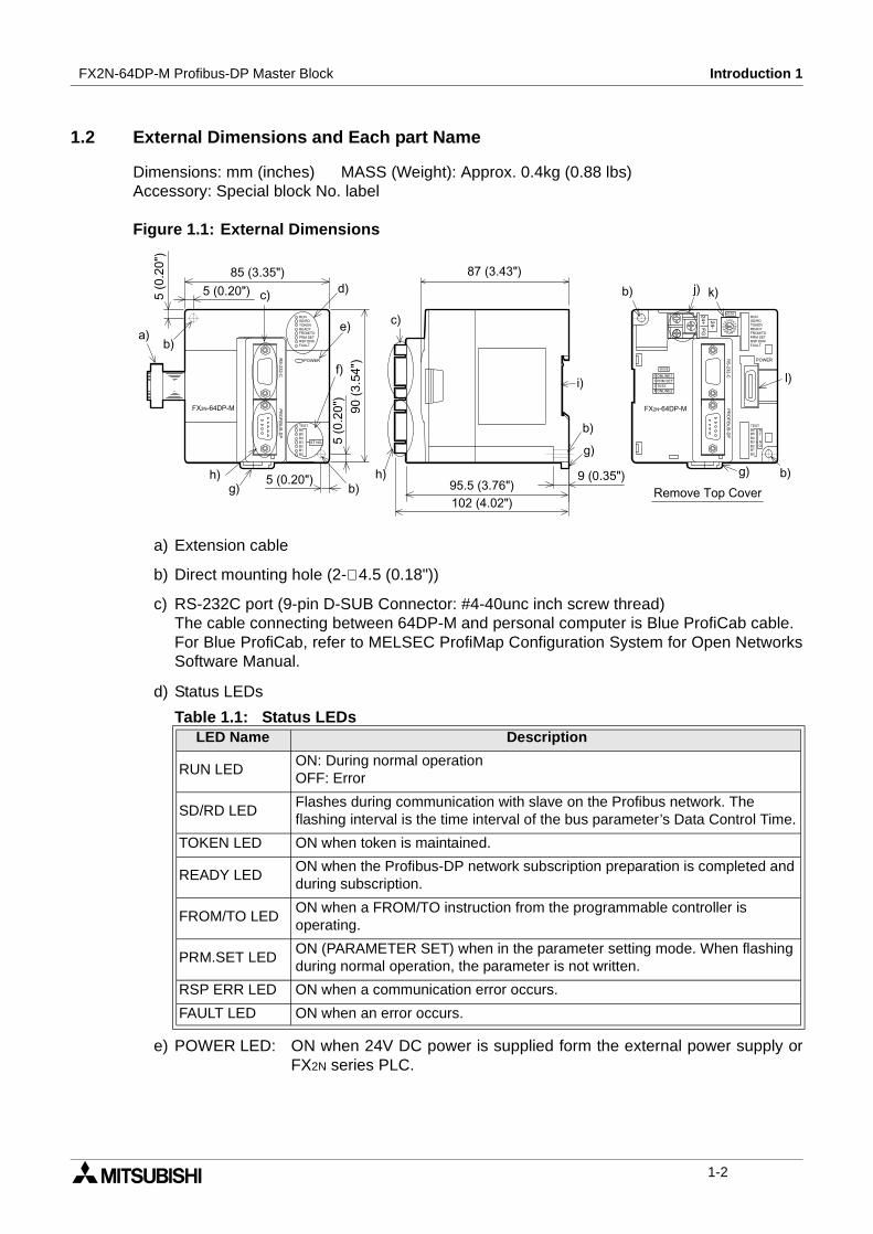
1.2 External Dimensions and Each part Name
Dimensions: mm (inches) MASS (Weight): Approx. 0.4kg (0.88 lbs)Accessory: Special block No. label
Figure 1.1: External Dimensions
a) Extension cable
b) Direct mounting hole (2-∅ 4.5 (0.18"))
c) RS-232C port (9-pin D-SUB Connector: #4-40unc inch screw thread)The cable connecting between 64DP-M and personal computer is Blue ProfiCab cable.For Blue ProfiCab, refer to MELSEC ProfiMap Configuration System for Open NetworksSoftware Manual.
d) Status LEDs
e) POWER LED: ON when 24V DC power is supplied form the external power supply orFX2N series PLC.
Table 1.1: Status LEDsLED Name Description
RUN LEDON: During normal operationOFF: Error
SD/RD LEDFlashes during communication with slave on the Profibus network. Theflashing interval is the time interval of the bus parameter’s Data Control Time.
TOKEN LED ON when token is maintained.
READY LEDON when the Profibus-DP network subscription preparation is completed andduring subscription.
FROM/TO LEDON when a FROM/TO instruction from the programmable controller isoperating.
PRM.SET LEDON (PARAMETER SET) when in the parameter setting mode. When flashingduring normal operation, the parameter is not written.
RSP ERR LED ON when a communication error occurs.
FAULT LED ON when an error occurs.
!
"
#
$
!
%
&
"
#
'
!
&
! ( )
*
!&
+
,-./+
,01
1+.......
+
,
2/3+1+1,4,125,61+4/
,1
,1
1
,3-1
+1
1+
,3-1
7 8
+4
+1
1+..
+1
2/3
.
,01
,61
.
,4,
.
.
+,
/
+
,-./+
125
.
1.
2
1-2

FX2N-64DP-M Profibus-DP Master Block Introduction 1
f) TEST LED and STATION LED
g) Hook for mounting DIN rail
h) PROFIBUS-DP port (9-pin D-SUB Connector: #4-40unc inch screw thread)
i) Groove for mounting DIN rail (DIN 46277<DIN rail width: 35mm (1.38")>)
j) DC power supply terminals (screws terminal: M3)
k) Mode setting switch (Default setting: “0”) For mode, refer to Chapter 4.
l) port for extension cable
1.2.1 Pin configuration of Profibus-DP Connector
The connector is a 9-pin D-SUB (#4-40unc inch screw thread) type, the pin configuration isshown below.
Figure 1.2: Pin Layout of Profibus-DP Connector
Table 1.2: TEST LED and STATION LEDLED Name Description
TEST LED ON when self-diagnosis is executing.
STATIONLED
Displays the station address during normal operation. (Binary) Displays the testtype during self-diagnosis. (B0 ~ B6)
Table 1.3: Mode SwitchSwitch No. Mode
0 ONLINE1 (Normal service mode)
1 PRM SET (Parameter setting mode)
2 TEST (Self diagnostic mode)
3 ~ D Cannot use
E ONLINE2 (Extended service mode)
F Cannot use
Table 1.4: Profibus-DP Connector PinConfiguration
Pin No.SignalName
Meaning
3 RXD/TXD-P Receive/transmit-Data-P
5 DGND Data Ground
6 VP Voltage-Plus
8 RXD/TXD-N Receive/transmit-Data-N
1, 2, 4,7, 9
NC Pin not assigned
AssignedNot assigned
12
6
3
79
54
8
1-3
FX2N-64DP-M Profibus-DP Master Block Introduction 1
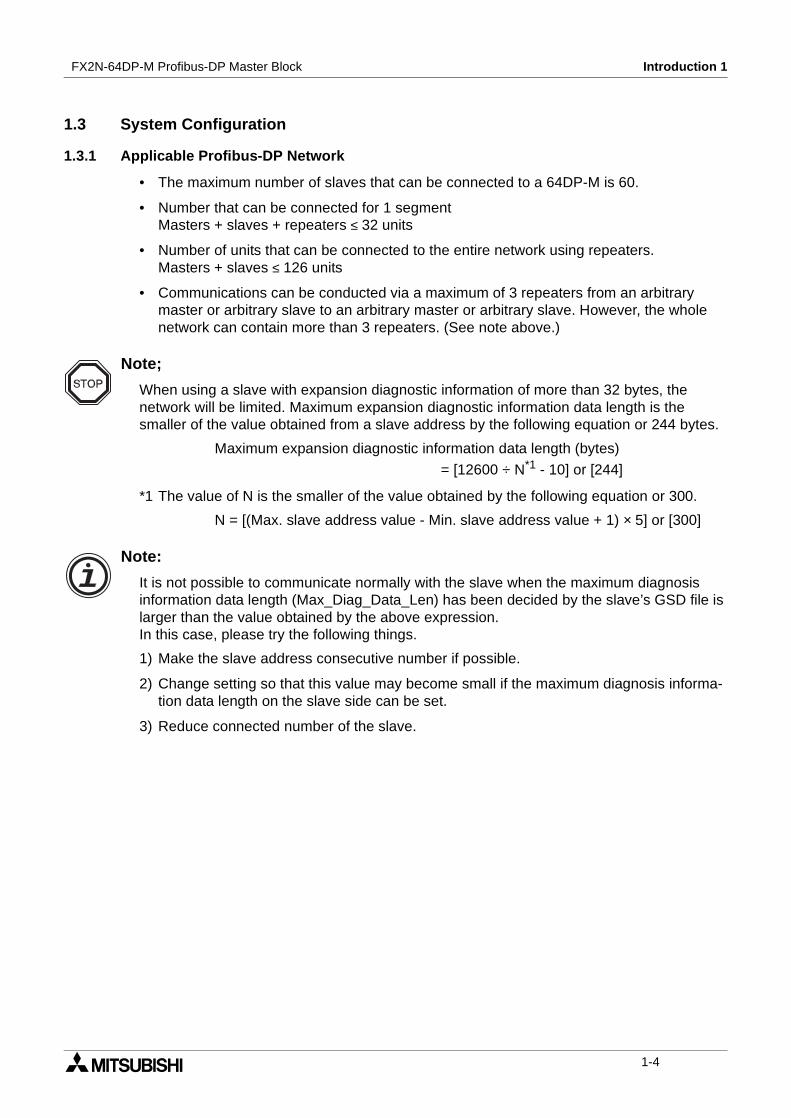
1.3 System Configuration
1.3.1 Applicable Profibus-DP Network
• The maximum number of slaves that can be connected to a 64DP-M is 60.
• Number that can be connected for 1 segmentMasters + slaves + repeaters ≤ 32 units
• Number of units that can be connected to the entire network using repeaters.Masters + slaves ≤ 126 units
• Communications can be conducted via a maximum of 3 repeaters from an arbitrarymaster or arbitrary slave to an arbitrary master or arbitrary slave. However, the wholenetwork can contain more than 3 repeaters. (See note above.)
Note;
When using a slave with expansion diagnostic information of more than 32 bytes, thenetwork will be limited. Maximum expansion diagnostic information data length is thesmaller of the value obtained from a slave address by the following equation or 244 bytes.
Maximum expansion diagnostic information data length (bytes)
= [12600 ÷ N*1 - 10] or [244]
*1 The value of N is the smaller of the value obtained by the following equation or 300.
N = [(Max. slave address value - Min. slave address value + 1) × 5] or [300]
Note:
It is not possible to communicate normally with the slave when the maximum diagnosisinformation data length (Max_Diag_Data_Len) has been decided by the slave’s GSD file islarger than the value obtained by the above expression.In this case, please try the following things.
1) Make the slave address consecutive number if possible.
2) Change setting so that this value may become small if the maximum diagnosis informa-tion data length on the slave side can be set.
3) Reduce connected number of the slave.
1-4
FX2N-64DP-M Profibus-DP Master Block Introduction 1
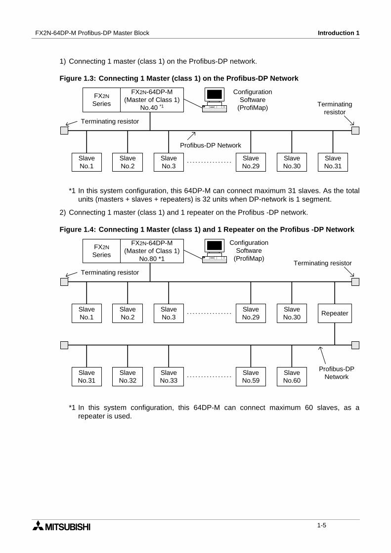
1) Connecting 1 master (class 1) on the Profibus-DP network.
Figure 1.3: Connecting 1 Master (class 1) on the Profibus-DP Network
*1 In this system configuration, this 64DP-M can connect maximum 31 slaves. As the totalunits (masters + slaves + repeaters) is 32 units when DP-network is 1 segment.
2) Connecting 1 master (class 1) and 1 repeater on the Profibus -DP network.
Figure 1.4: Connecting 1 Master (class 1) and 1 Repeater on the Profibus -DP Network
*1 In this system configuration, this 64DP-M can connect maximum 60 slaves, as arepeater is used.
FX2N
Series
FX2N-64DP-M(Master of Class 1)
No.40 *1
SlaveNo.1
SlaveNo.2
SlaveNo.3
SlaveNo.31
SlaveNo.30
SlaveNo.29
Profibus-DP Network
Terminating resistor
Terminatingresistor
ConfigurationSoftware
(ProfiMap)
FX2N
Series
FX2N-64DP-M(Master of Class 1)
No.80 *1
SlaveNo.1
SlaveNo.2
SlaveNo.3
RepeaterSlaveNo.30
SlaveNo.29
Profibus-DPNetwork
Terminating resistorTerminating resistor
SlaveNo.60
SlaveNo.59
SlaveNo.33
SlaveNo.32
SlaveNo.31
ConfigurationSoftware
(ProfiMap)
1-5
FX2N-64DP-M Profibus-DP Master Block Introduction 1
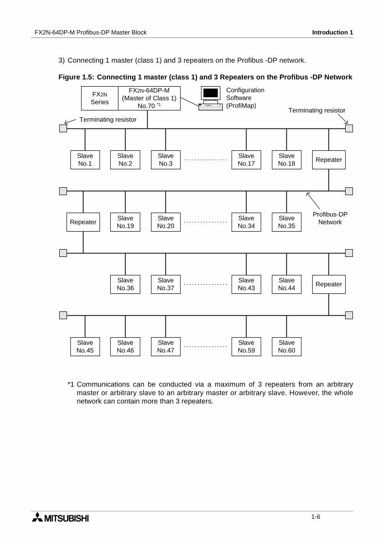
3) Connecting 1 master (class 1) and 3 repeaters on the Profibus -DP network.
Figure 1.5: Connecting 1 master (class 1) and 3 Repeaters on the Profibus -DP Network
*1 Communications can be conducted via a maximum of 3 repeaters from an arbitrarymaster or arbitrary slave to an arbitrary master or arbitrary slave. However, the wholenetwork can contain more than 3 repeaters.
FX2N
Series
FX2N-64DP-M(Master of Class 1)
No.70 *1
SlaveNo.1
SlaveNo.2
SlaveNo.3
RepeaterSlaveNo.18
SlaveNo.17
Profibus-DPNetwork
Terminating resistorTerminating resistor
SlaveNo.35
SlaveNo.34
SlaveNo.20
SlaveNo.19
Repeater
SlaveNo.44
SlaveNo.43
SlaveNo.37
SlaveNo.36
Repeater
SlaveNo.60
SlaveNo.59
SlaveNo.47
SlaveNo.46
SlaveNo.45
ConfigurationSoftware(ProfiMap)
1-6
FX2N-64DP-M Profibus-DP Master Block Introduction 1
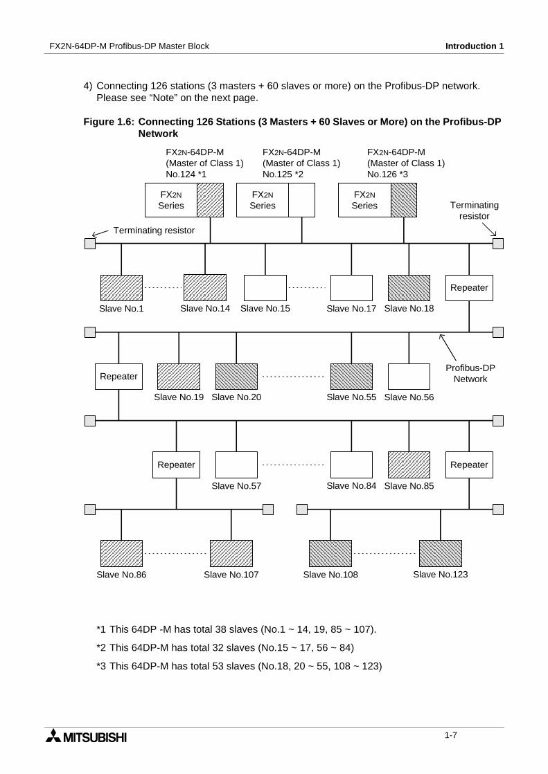
4) Connecting 126 stations (3 masters + 60 slaves or more) on the Profibus-DP network.Please see “Note” on the next page.
Figure 1.6: Connecting 126 Stations (3 Masters + 60 Slaves or More) on the Profibus-DPNetwork
*1 This 64DP -M has total 38 slaves (No.1 ~ 14, 19, 85 ~ 107).
*2 This 64DP-M has total 32 slaves (No.15 ~ 17, 56 ~ 84)
*3 This 64DP-M has total 53 slaves (No.18, 20 ~ 55, 108 ~ 123)
FX2N
Series
Repeater
Profibus-DPNetwork
Terminating resistor
Terminatingresistor
Repeater
Repeater Repeater
Slave No.1 Slave No.14 Slave No.15 Slave No.17 Slave No.18
Slave No.56Slave No.55Slave No.20Slave No.19
Slave No.57 Slave No.84 Slave No.85
Slave No.86 Slave No.107 Slave No.108 Slave No.123
FX2N-64DP-M(Master of Class 1)No.124 *1
FX2N-64DP-M(Master of Class 1)No.125 *2
FX2N-64DP-M(Master of Class 1)No.126 *3
FX2N
SeriesFX2N
Series
1-7

FX2N-64DP-M Profibus-DP Master Block Introduction 1
Note
In Configuration that use multiple master stations (multimaster configuration), whenreconnecting a cable after disconnecting a PROFIBUS cable for 1 master that isexchanging data at allow baud rate, the communications of the master for which the cableis not disconnected could stop and the slave output could be turned OFF. To prevent this,the master PROFIBUS cable must be secured.
In addition, there is a high possibility that the above phenomena can be avoided if care istaken with the following points when configuring a system.
1) Set the slave watchdog timer setting value to larger than (TTr × G)/BR. However,
TTr: Target token rotation time (Unit: Bit Time)
G: Gap update factor
BR: Baud rate (Unit: bps)
2) Use a high baud rate.
3) The HSA (Highest Station Address) value is made to match the maximum station No.that is actually connected.
1-8

FX2N-64DP-M Profibus-DP Master Block Introduction 1
1.3.2 Applicable Programmable Controller
For setting up a system, the 64DP-M can be connected directly to the FX2N seriesprogrammable controller’s extension port, or to any other extension unit / block’s right sideextension port.
The 64 DP-M occupies 8 points of I/O on the FX2N’s expansion bus. The 8 points can beallocated from either inputs or outputs. The maximum I/O for a FX2N system is 256 I/O.
1.4 Communication Time
The communication time is the data exchange time between FX2N series programmablecontroller and slave on the Profibus-DP. This communication time can be requested by theexpression below.
Communication time = Total of polling cycle time*1 for each slave + (2 × Scan time*2)
*1 The polling cycle time is a data update cycle time between 64DP-M and slave on the DP-network. For how to obtain the polling cycle time, refer to subsection 1.4.1.
*2 The scan time can be checked with D8010 ~ D8012 of the programmable controller.
Note;
The polling cycle time and FROM/TO instruction are operated asynchronously. If data iswritten to the 64DP-M in the polling cycle, this data will move to the system area on the nextpolling cycle.
Table 1.5: Applicable Programmable ControllerProgrammable Controller Type Version
FX2N seriesFrom first product(All versions)
1-9

FX2N-64DP-M Profibus-DP Master Block Introduction 1
1.4.1 Polling Cycle Time
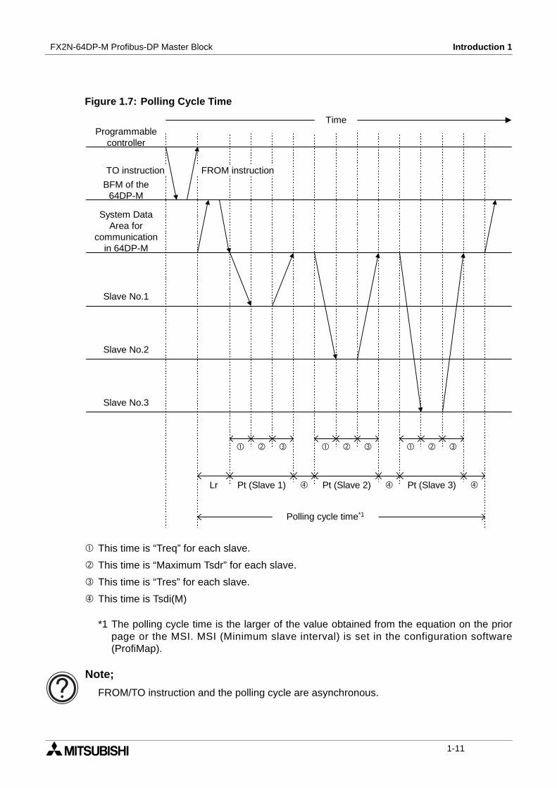
An explanation of the polling cycle time for one master is given in figure 1.6. In this examplethere are 3 slaves. The polling cycle time is the larger of:
Explanation of MSI, Pt (Slave (i)), Treq (i), Max Tsdr (i), Tres (i), Tsdi (M), Lr see following table.
Table 1.6: Wording for Polling Cycle TimeWording Description
Pt (Slave (i)) The polling time of the slave = Treq (i) + Max Tsdr (i) + Tres (i)
Treq (i)The request transmission time of the slave =(number of output bytes to this slave + 9) × 11) / baud rate
Max tsdr (i)Response time of the slave =(This value is recorded in this slave GSD file.) / baud rate
Tres (i)Response transmission time of the slave -(Number of input bytes from this slave + 9) × 11) / baud rate
Tsdi (M)Processing time of master request/response =(This value is recorded in this slave GSD file.) / baud rate
Lr Data refresh time = Max. 260 ms + 5 ms × number of slaves
MSI Minimum slave interval is set in the configuration software (ProfiMap).
Polling cycle time = Pt (Slave (i)) + Tsdi (M) + Lr]the higher value of [MSI] or [ Σi = 1
Number of slaves
1-10
FX2N-64DP-M Profibus-DP Master Block Introduction 1
Figure 1.7: Polling Cycle Time
This time is “Treq” for each slave.
This time is “Maximum Tsdr” for each slave.
This time is “Tres” for each slave.
This time is Tsdi(M)
*1 The polling cycle time is the larger of the value obtained from the equation on the priorpage or the MSI. MSI (Minimum slave interval) is set in the configuration software(ProfiMap).
Note;
FROM/TO instruction and the polling cycle are asynchronous.
Programmablecontroller
BFM of the64DP-M
System DataArea for
communicationin 64DP-M
Slave No.1
Slave No.2
Slave No.3
Lr Pt (Slave 1) Pt (Slave 2) Pt (Slave 3)
Polling cycle time*1
Time
FROM instructionTO instruction
1-11

FX2N-64DP-M Profibus-DP Master Block Introduction 1
MEMO
1-12

Wiring and Mounting 2FX2N-64DP-M Profibus-DP Master Block
2. Wiring and Mounting
2.1 Mounting
2.1.1 Arrangements
The 64DP-M connects on the right side of an FX2N series main unit or extension unit/block(include special function block). For further information of mounting arrangements, refer toFX2N Series Hardware Manual.
2.1.2 Mounting
Mounting method of the 64DP-M is DIN rail mounting or direct wall mounting.
1) DIN rail mounting
• Align the upper side of the DIN rail mounting groove of the 64DP-M with a DIN rail*1 (),and push it on the DIN rail(). See Figure 2.1.
• When removing the 64DP-M from the DIN rail, the hook for DIN rail is pulled (), and the64DP-M is removed (). See Figure 2.2.
Figure 2.1: Attach to DIN Rail
Figure 2.2: Remove from DIN Rail
*1 Uses DIN 46277 <35mm (1.38")>
2) Direct mounting to back walls
The 64DP-M can be mounted with M4 screws by using the direct mounting holes.An interval space between each unit of 1 ~ 2 mm is necessary.
2-1
FX2N-64DP-M Profibus-DP Master Block Wiring and Mounting 2
2.2 Wiring
2.2.1 Caution
1) Do not lay signal cable near to high voltage power cable or house them in the sametrunking duct. Effects of noise or surge induction may occur. Keep signal cables a safedistance of more than 100 mm (3.94") from these power cables.
2) Ground the shield wire or the shield of a shielded cable at one point on the programmablecontroller. Do not, however, ground at the same point as high voltage lines.
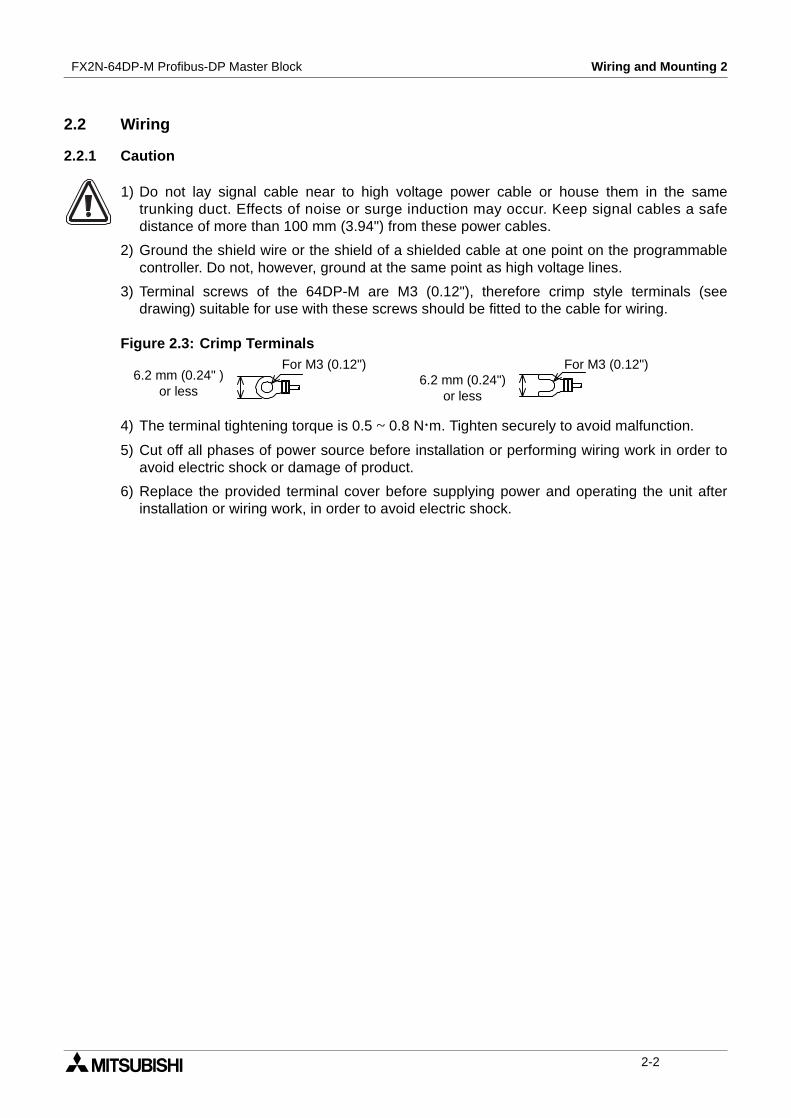
3) Terminal screws of the 64DP-M are M3 (0.12"), therefore crimp style terminals (seedrawing) suitable for use with these screws should be fitted to the cable for wiring.
Figure 2.3: Crimp Terminals
4) The terminal tightening torque is 0.5 ~ 0.8 Nm. Tighten securely to avoid malfunction.
5) Cut off all phases of power source before installation or performing wiring work in order toavoid electric shock or damage of product.
6) Replace the provided terminal cover before supplying power and operating the unit afterinstallation or wiring work, in order to avoid electric shock.
6.2 mm (0.24" )or less
For M3 (0.12")6.2 mm (0.24")
or less
For M3 (0.12")
2-2
FX2N-64DP-M Profibus-DP Master Block Wiring and Mounting 2
2.2.2 Wiring
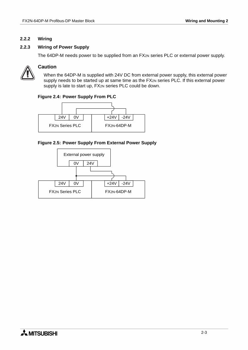
2.2.3 Wiring of Power Supply
The 64DP-M needs power to be supplied from an FX2N series PLC or external power supply.
Caution
When the 64DP-M is supplied with 24V DC from external power supply, this external powersupply needs to be started up at same time as the FX2N series PLC. If this external powersupply is late to start up, FX2N series PLC could be down.
Figure 2.4: Power Supply From PLC
Figure 2.5: Power Supply From External Power Supply
24V 0V
FX2N Series PLC FX2N-64DP-M
+24V -24V
24V 0V
FX2N Series PLC FX2N-64DP-M
+24V -24V
24V0V
External power supply
2-3

FX2N-64DP-M Profibus-DP Master Block Wiring and Mounting 2
2.2.4 Wiring of Profibus-DP
To connect the 64DP-M to a Profibus-DP network use only the Profibus connectors andshielded twisted-pair cable complying with EN50170. For Profibus connectors see the Profibusconnector manual.
Figure 2.6: Wiring
Figure 2.7: Profibus Connection
2.2.5 Terminating resistor
The units at each end of the Profibus-DP network must have a terminating resistor. This willeither be in the master or slave unit or in the Profibus connector.
However, the 64DP-M does not have a terminating resistance built-in.
For Profibus connection,refer to Figure 2.7.
Shielded twisted-paircable complying withEN50170 to Profibus-DPnetwork
Grounding plate
Groundingresistance of100 Ω or less(Class D)
For noise prevention please attach at least 50 mm(1.97") of the twisted-pair cable along thegrounding plate to which the ground terminal isconnected.
+24 -24FG
External power supply or theservice power supply of PLC
FX2N-64DP-MProfibus-DP MasterBlock
RS-232C connectorfor connectingconfiguration software(ProfiMap)
Shielded twisted-pair cable toProfibus-DP network
FX2N-64DP-M Profibus-DPMaster Block
2-4
Specifications 3FX2N-64DP-M Profibus-DP Master Block
3. Specifications
3.1 General Specifications
3.2 Power Supply Specifications
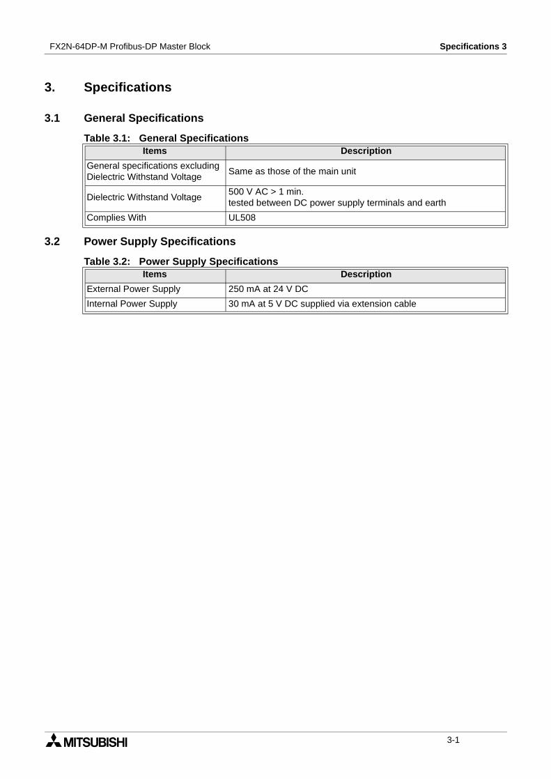
Table 3.1: General SpecificationsItems Description
General specifications excludingDielectric Withstand Voltage
Same as those of the main unit
Dielectric Withstand Voltage500 V AC > 1 min.tested between DC power supply terminals and earth
Complies With UL508
Table 3.2: Power Supply SpecificationsItems Description
External Power Supply 250 mA at 24 V DC
Internal Power Supply 30 mA at 5 V DC supplied via extension cable
3-1
FX2N-64DP-M Profibus-DP Master Block Specifications 3
3.3 Performance Specifications
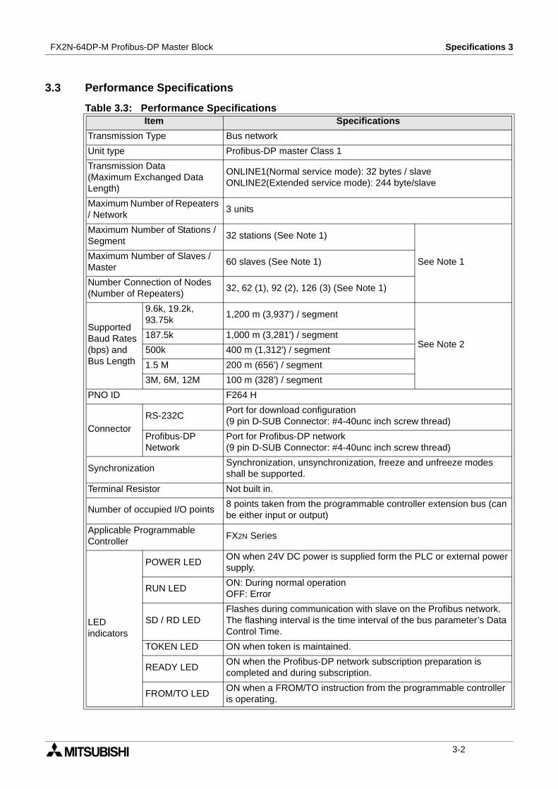
Table 3.3: Performance SpecificationsItem Specifications
Transmission Type Bus network
Unit type Profibus-DP master Class 1
Transmission Data(Maximum Exchanged DataLength)
ONLINE1(Normal service mode): 32 bytes / slaveONLINE2(Extended service mode): 244 byte/slave
Maximum Number of Repeaters/ Network
3 units
Maximum Number of Stations /Segment
32 stations (See Note 1)
See Note 1Maximum Number of Slaves /Master
60 slaves (See Note 1)
Number Connection of Nodes(Number of Repeaters)
32, 62 (1), 92 (2), 126 (3) (See Note 1)
SupportedBaud Rates(bps) andBus Length
9.6k, 19.2k,93.75k
1,200 m (3,937') / segment
See Note 2187.5k 1,000 m (3,281') / segment
500k 400 m (1,312') / segment
1.5 M 200 m (656') / segment
3M, 6M, 12M 100 m (328') / segment
PNO ID F264 H
ConnectorRS-232C
Port for download configuration(9 pin D-SUB Connector: #4-40unc inch screw thread)
Profibus-DPNetwork
Port for Profibus-DP network(9 pin D-SUB Connector: #4-40unc inch screw thread)
SynchronizationSynchronization, unsynchronization, freeze and unfreeze modesshall be supported.
Terminal Resistor Not built in.
Number of occupied I/O points8 points taken from the programmable controller extension bus (canbe either input or output)
Applicable ProgrammableController
FX2N Series
LEDindicators
POWER LEDON when 24V DC power is supplied form the PLC or external powersupply.
RUN LEDON: During normal operationOFF: Error
SD / RD LEDFlashes during communication with slave on the Profibus network.The flashing interval is the time interval of the bus parameter’s DataControl Time.
TOKEN LED ON when token is maintained.
READY LEDON when the Profibus-DP network subscription preparation iscompleted and during subscription.
FROM/TO LEDON when a FROM/TO instruction from the programmable controlleris operating.
3-2
FX2N-64DP-M Profibus-DP Master Block Specifications 3
Note 1;
When using a slave with expansion diagnostic information of more than 32 bytes, thenetwork will be limited. Maximum expansion diagnostic information data length is thesmaller of the value obtained from a slave address by the following equation or 244 bytes.
Maximum expansion diagnostic information data length (bytes)
= [12600 ÷ N*1 - 10] or [244]
*1 The value of N is the smaller of the value obtained by the following equation or 300.
N = [(Max. slave address value - Min. slave address value + 1) × 5] or [300]
It is not possible to communicate normally with the slave when the maximum diagnosisinformation data length (Max_Diag_Data_Len) has been decided by the slave’s GSD file islarger than the value obtained by the above expression.In this case, please try the following things.
1) Make the slave address consecutive number if possible.
2) Change setting so that this value may become small if the maximum diagnosis informa-tion data length on the slave side can be set.
3) Reduce connected number of the slave.
Note 2;
Length that the bus can be expanded by using repeaters.
Maximum Bus Length = (“Number of repeaters” + 1) × “Bus Length / segment”
LEDindicators
PRM.SET LEDON (PARAMETER SET) when in the parameter setting mode. Whenflashing during normal operation, the parameter is not written.
RSP ERR LED ON when a communication error occurs.
FAULT LED ON when an error occurs.
TEST LED ON when self-diagnosis is executing.
STATION LEDDisplays the station address during normal operation.(Binary)Displays the test type during a self-diagnosis. (B0 to B6)
Table 3.4: Maximum Bus Length and Baud Rate
Baud Rate (bps)Maximum Bus Length
No repeater 1 repeater 2 repeaters 3 repeaters
9.6k, 19.2k, 93.75k 1,200 m (3,937') 2,400 m (7,874') 3,600 m (11,811') 4,800 m (15,748')
187.5k 1,000 m (3,281') 2,000 m (6,562') 3,000 (9,843') 4,000 m (13,123')
500k 400 m (1,312') 800 m (2,625') 1,200 m (3,937') 1,600 m (5,249')
1.5 M 200 m (656') 400 m (1,312') 600 m (1,969') 800 m (2,625')
3M, 6M, 12M 100 m (328') 200 m (656') 300 m (984') 400 m (1,312')
Table 3.3: Performance SpecificationsItem Specifications
3-3
FX2N-64DP-M Profibus-DP Master Block Specifications 3
MEMO
3-4
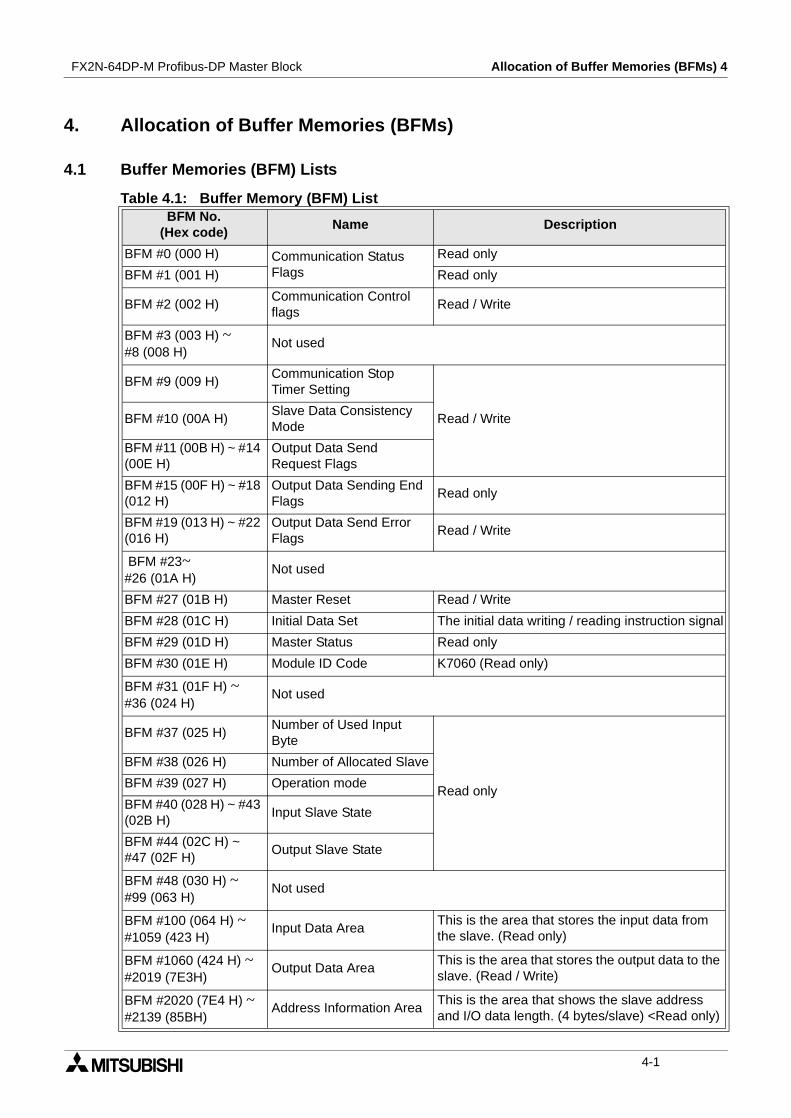
Allocation of Buffer Memories (BFMs) 4FX2N-64DP-M Profibus-DP Master Block
4. Allocation of Buffer Memories (BFMs)
4.1 Buffer Memories (BFM) Lists
Table 4.1: Buffer Memory (BFM) ListBFM No.
(Hex code)Name Description
BFM #0 (000 H) Communication StatusFlags
Read only
BFM #1 (001 H) Read only
BFM #2 (002 H)Communication Controlflags
Read / Write
BFM #3 (003 H) ~#8 (008 H)
Not used
BFM #9 (009 H)Communication StopTimer Setting
Read / WriteBFM #10 (00A H)Slave Data ConsistencyMode
BFM #11 (00B H) ~ #14(00E H)
Output Data SendRequest Flags
BFM #15 (00F H) ~ #18(012 H)
Output Data Sending EndFlags
Read only
BFM #19 (013 H) ~ #22(016 H)
Output Data Send ErrorFlags
Read / Write
BFM #23~#26 (01A H)
Not used
BFM #27 (01B H) Master Reset Read / Write
BFM #28 (01C H) Initial Data Set The initial data writing / reading instruction signal
BFM #29 (01D H) Master Status Read only
BFM #30 (01E H) Module ID Code K7060 (Read only)
BFM #31 (01F H) ~#36 (024 H)
Not used
BFM #37 (025 H)Number of Used InputByte
Read only
BFM #38 (026 H) Number of Allocated Slave
BFM #39 (027 H) Operation mode
BFM #40 (028 H) ~ #43(02B H)
Input Slave State
BFM #44 (02C H) ~#47 (02F H)
Output Slave State
BFM #48 (030 H) ~#99 (063 H)
Not used
BFM #100 (064 H) ~#1059 (423 H)
Input Data AreaThis is the area that stores the input data fromthe slave. (Read only)
BFM #1060 (424 H) ~#2019 (7E3H)
Output Data AreaThis is the area that stores the output data to theslave. (Read / Write)
BFM #2020 (7E4 H) ~#2139 (85BH)
Address Information AreaThis is the area that shows the slave addressand I/O data length. (4 bytes/slave) <Read only)
4-1
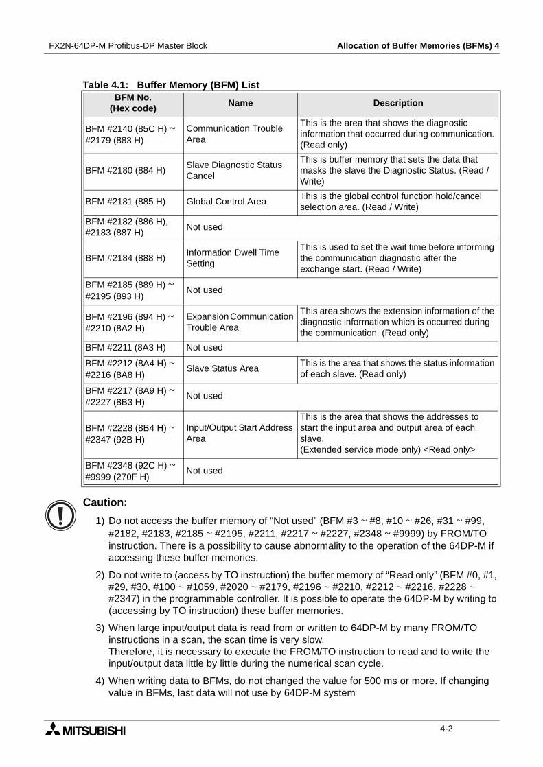
FX2N-64DP-M Profibus-DP Master Block Allocation of Buffer Memories (BFMs) 4
Caution:
1) Do not access the buffer memory of “Not used” (BFM #3 ~ #8, #10 ~ #26, #31 ~ #99,#2182, #2183, #2185 ~ #2195, #2211, #2217 ~ #2227, #2348 ~ #9999) by FROM/TOinstruction. There is a possibility to cause abnormality to the operation of the 64DP-M ifaccessing these buffer memories.
2) Do not write to (access by TO instruction) the buffer memory of “Read only” (BFM #0, #1,#29, #30, #100 ~ #1059, #2020 ~ #2179, #2196 ~ #2210, #2212 ~ #2216, #2228 ~#2347) in the programmable controller. It is possible to operate the 64DP-M by writing to(accessing by TO instruction) these buffer memories.
3) When large input/output data is read from or written to 64DP-M by many FROM/TOinstructions in a scan, the scan time is very slow.Therefore, it is necessary to execute the FROM/TO instruction to read and to write theinput/output data little by little during the numerical scan cycle.
4) When writing data to BFMs, do not changed the value for 500 ms or more. If changingvalue in BFMs, last data will not use by 64DP-M system
BFM #2140 (85C H) ~#2179 (883 H)
Communication TroubleArea
This is the area that shows the diagnosticinformation that occurred during communication.(Read only)
BFM #2180 (884 H)Slave Diagnostic StatusCancel
This is buffer memory that sets the data thatmasks the slave the Diagnostic Status. (Read /Write)
BFM #2181 (885 H) Global Control AreaThis is the global control function hold/cancelselection area. (Read / Write)
BFM #2182 (886 H),#2183 (887 H)
Not used
BFM #2184 (888 H)Information Dwell TimeSetting
This is used to set the wait time before informingthe communication diagnostic after theexchange start. (Read / Write)
BFM #2185 (889 H) ~#2195 (893 H)
Not used
BFM #2196 (894 H) ~#2210 (8A2 H)
Expansion CommunicationTrouble Area
This area shows the extension information of thediagnostic information which is occurred duringthe communication. (Read only)
BFM #2211 (8A3 H) Not used
BFM #2212 (8A4 H) ~#2216 (8A8 H)
Slave Status AreaThis is the area that shows the status informationof each slave. (Read only)
BFM #2217 (8A9 H) ~#2227 (8B3 H)
Not used
BFM #2228 (8B4 H) ~#2347 (92B H)
Input/Output Start AddressArea
This is the area that shows the addresses tostart the input area and output area of eachslave.(Extended service mode only) <Read only>
BFM #2348 (92C H) ~#9999 (270F H)
Not used
Table 4.1: Buffer Memory (BFM) ListBFM No.
(Hex code)Name Description
4-2
FX2N-64DP-M Profibus-DP Master Block Allocation of Buffer Memories (BFMs) 4
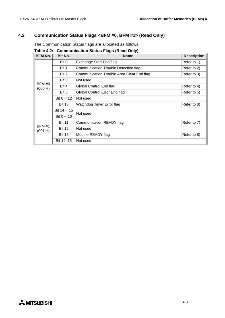
4.2 Communication Status Flags <BFM #0, BFM #1> (Read Only)
The Communication Status flags are allocated as follows.
Table 4.2: Communication Status Flags (Read Only)BFM No. Bit No. Name Description
BFM #0(000 H)
Bit 0 Exchange Start End flag Refer to 1)
Bit 1 Communication Trouble Detection flag Refer to 2)
Bit 2 Communication Trouble Area Clear End flag Refer to 3)
Bit 3 Not used
Bit 4 Global Control End flag Refer to 4)
Bit 5 Global Control Error End flag Refer to 5)
Bit 6 ~ 12 Not used
Bit 13 Watchdog Timer Error flag Refer to 6)
Bit 14 ~ 15Not used
BFM #1(001 H)
Bit 0 ~ 10
Bit 11 Communication READY flag Refer to 7)
Bit 12 Not used
Bit 13 Module READY flag Refer to 8)
Bit 14, 15 Not used
4-3
FX2N-64DP-M Profibus-DP Master Block Allocation of Buffer Memories (BFMs) 4
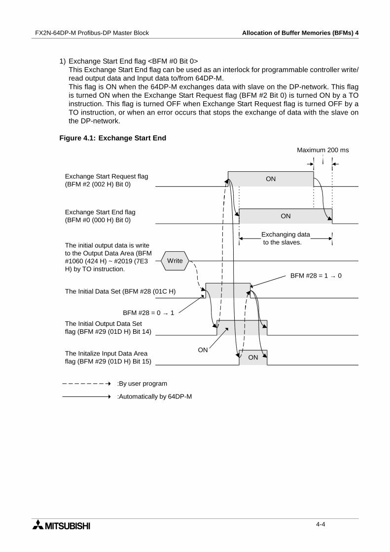
1) Exchange Start End flag <BFM #0 Bit 0>This Exchange Start End flag can be used as an interlock for programmable controller write/read output data and Input data to/from 64DP-M.This flag is ON when the 64DP-M exchanges data with slave on the DP-network. This flagis turned ON when the Exchange Start Request flag (BFM #2 Bit 0) is turned ON by a TOinstruction. This flag is turned OFF when Exchange Start Request flag is turned OFF by aTO instruction, or when an error occurs that stops the exchange of data with the slave onthe DP-network.
Figure 4.1: Exchange Start End
Write
Exchange Start Request flag(BFM #2 (002 H) Bit 0)
Exchange Start End flag(BFM #0 (000 H) Bit 0)
Maximum 200 ms
ON
ON
The initial output data is writeto the Output Data Area (BFM#1060 (424 H) ~ #2019 (7E3H) by TO instruction.
Exchanging datato the slaves.
The Initial Data Set (BFM #28 (01C H)
BFM #28 = 0 → 1
BFM #28 = 1 → 0
The Initial Output Data Setflag (BFM #29 (01D H) Bit 14)
The Initalize Input Data Areaflag (BFM #29 (01D H) Bit 15)
ONON
:By user program
:Automatically by 64DP-M
4-4

FX2N-64DP-M Profibus-DP Master Block Allocation of Buffer Memories (BFMs) 4
Note;
• Before the Exchange Start Request flag is turned ON the output data initial value mustbe written to BFM #1060 (424 H) ~ #2019 (7E3 H).For the Initial Data Set buffer memory, refer to section 4.7. For the Initial Output Data Setflag and the Initialize Input Data Area flag, refer to section 4.8.
• There is a possibility that it is not possible to communicate with the slave, even if theExchange Start Request flag (BFM #2 Bit 0) is turned ON, when the slave power supplyis turned ON simultaneously with 64DP-M.Therefore, please turn ON the Exchange Start Request flag after CommunicationREADY flag (BFM #1 Bit 11) is turned ON.
• It is not possible to stop the communication with slaves, even if the FX2N plc is in STOP.Therefore, please turn OFF the Exchange Start Request flag, or each power supply ofthe 64DP-M and FX2N plc, before the FX2N plc is in STOP.
2) Communication Trouble Detection flag <BFM #0 Bit 1>The Communication Trouble Detection flag can check that the communication diagnosticerror occurred.This flag is turned ON when the communication diagnostic error occurs. At the same timethe RSP ERR LED turns ON, and Diagnostic Information is stored in BFM #2140 ~ #2179<Communication Trouble Area>. This flag is turned OFF when the Communication TroubleDetection Flag Reset flag (BFM #2 Bit 1) turns ON by a TO instruction. At the same time,the RSP ERR LED is turned OFF.
Figure 4.2: Communication Trouble Detection Flag
Note;
• If this flag is turned ON, Diagnostic Information needs to be read from theCommunication Trouble Area area (BFM #2140 ~ #2179) by a FROM instruction.
• The Communication Trouble Detection Reset flag (BFM #2 Bit 1) is turned OFF by a TOinstruction after it has been confirmed that the Communication Trouble Detection flag(BFM #0 Bit 1) has been turned OFF.
Communication Trouble Detection Flag Reset flag(BFM #2 (002 H) Bit 1)
Communication Trouble Detection flag(BFM #0 (000 H) Bit 1)
ON
ON
The Diagnostic Information is readform the Communication TroubleArea <BFM #2140 (85C H) ~ #2179(883 H)> by FROM instruction. Read
:By user program
:Automatically by 64DP-M
4-5

FX2N-64DP-M Profibus-DP Master Block Allocation of Buffer Memories (BFMs) 4
3) Communication Trouble Area Clear End flag <BFM #0 Bit 2>The Communication Trouble Area Clear End flag can check that all of the CommunicationTrouble Area (BFM #2140 ~ #2179) and the Expansion Communication Trouble Area (BFM#2196 ~ #2210) are cleared.This flag is turned ON when all of the Communication Trouble Area and ExpansionCommunication Trouble Area are cleared by turning ON the Communication Trouble AreaClear Request flag (BFM #2 Bit 2). This flag is turned OFF when the CommunicationTrouble Area Clear Request is turned OFF.
Figure 4.3: Communication Trouble Area Clear End Flag
Note;
The Communication Trouble Area Clear Request flag (BFM #2 Bit 2) is turned OFF by a TOinstruction after it has been confirmed that the Communication Trouble Area Clear End flag(BFM #0 Bit 2) has been turned ON.
Communication Trouble Area Clear Request flag(BFM #2 (002 H) Bit 2)
Communication Trouble Area Clear End flag(BFM #0 (000 H) Bit 2) ON
ON
:By user program
:Automatically by 64DP-M
4-6
FX2N-64DP-M Profibus-DP Master Block Allocation of Buffer Memories (BFMs) 4
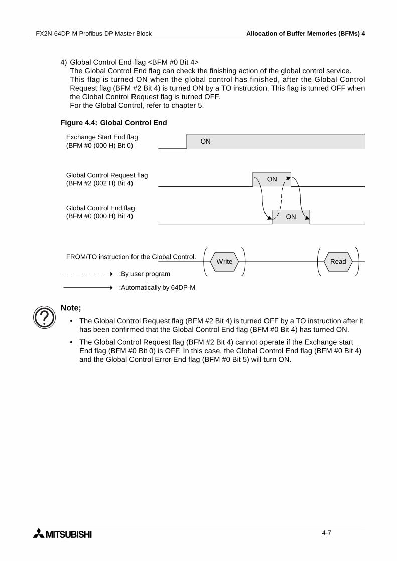
4) Global Control End flag <BFM #0 Bit 4>The Global Control End flag can check the finishing action of the global control service.This flag is turned ON when the global control has finished, after the Global ControlRequest flag (BFM #2 Bit 4) is turned ON by a TO instruction. This flag is turned OFF whenthe Global Control Request flag is turned OFF.For the Global Control, refer to chapter 5.
Figure 4.4: Global Control End
Note;
• The Global Control Request flag (BFM #2 Bit 4) is turned OFF by a TO instruction after ithas been confirmed that the Global Control End flag (BFM #0 Bit 4) has turned ON.
• The Global Control Request flag (BFM #2 Bit 4) cannot operate if the Exchange startEnd flag (BFM #0 Bit 0) is OFF. In this case, the Global Control End flag (BFM #0 Bit 4)and the Global Control Error End flag (BFM #0 Bit 5) will turn ON.
Global Control Request flag(BFM #2 (002 H) Bit 4)
Global Control End flag(BFM #0 (000 H) Bit 4) ON
Exchange Start End flag(BFM #0 (000 H) Bit 0)
ON
ON
Write ReadFROM/TO instruction for the Global Control.
:By user program
:Automatically by 64DP-M
4-7

FX2N-64DP-M Profibus-DP Master Block Allocation of Buffer Memories (BFMs) 4
5) Global Control Error End flag <BFM #0 Bit 5>The Global Control Error End flag can check that the global control service does notoperate.This flag is turned ON when the global control service does not operate. This flag is turnedOFF when the Global Control Request (BFM #2 Bit 4) turned ON → OFF.For global control, refer to chapter 5.
Figure 4.5: Global Control Error End Flag
Note;
• The Global Control Request flag (BFM #2 Bit 4) cannot operate if the Exchange startEnd flag (BFM #0 Bit 0) is OFF. In this case, the Global Control End flag (BFM #0 Bit 4)and the Global Control Error End flag (BFM #0 Bit 5) will turn ON.
• When the Global Control Error End flag is ON, the Input/Output data of the slave is notheld/deleted on the DP-network.
6) Watchdog Timer Error flag <BFM #0 Bit 13>The Watchdog Timer Error flag can check that the Watchdog Timer Error occurs.
Caution;
If this flag is turned ON, the 64DP-M can restart by the following method. When it is notpossible to restart by these methods, please contact a service representative.
• Adjust the Master Reset (BFM #27) from “1” →”0”.However, interval of 1 second or more is necessary when the Master Reset is changedfrom “1” →”0”. For explanation of the Master Reset (BFM #27), refer to section 4.5.
• Turn the Restart Request flag (BFM #2 Bit 13) ON → OFF.For the Restart Request flag, refer to subsection 4.3 6).
• Turn power supply of the 64DP-M and programmable controller OFF → ON.
Table 4.3: Watchdog Timer Error Flag StatusBit Status Description
ONWatchdog timer error occurs in the 64DP-M. In this case, 64DP-M cannot exchangeinput data and output data to the slaves on the DP-network.
OFF The 64DP-M is operating normally.
Global Control Request flag(BFM #2 (002 H) Bit 4)
Global Control Error End flag(BFM #0 (000 H) Bit 5) ON
ON
:By user program
:Automatically by 64DP-M
4-8

FX2N-64DP-M Profibus-DP Master Block Allocation of Buffer Memories (BFMs) 4
7) Communication READY flag <BFM #1 Bit 11>The Communication READY flag can be used as an interlock when the Exchange StartRequest flag (BFM #2 Bit 0) turn ON by a TO instruction.This flag is turned ON when the status of the 64DP-M can communicate to slaves on theDP-network, after the 64DP-M has started up and the Module READY flag (BFM #1 Bit 13)
has turned ON. This flag is turned OFF when an error*1 occurs in the 64DP-M, and it isimpossible to communicate with slaves on the DP-network.
*1 When this error occurs, the FAULT LED will be ON. For checking point of the FAULTLED, refer to chapter 10.
8) Module READY flag <BFM #1 Bit 13>The Module READY flag can check that the 64DP-M has started up. If this flag is OFF, the64DP-M cannot receive FORM/TO instructions form the programmable controller orcommunicate to slaves on the DP-network.This flag is turned ON when the 64DP-M is started up. Therefore, it is turned ON regardlessof the operation mode. This flag is OFF when the 64DP-M is powered down.
4-9
FX2N-64DP-M Profibus-DP Master Block Allocation of Buffer Memories (BFMs) 4
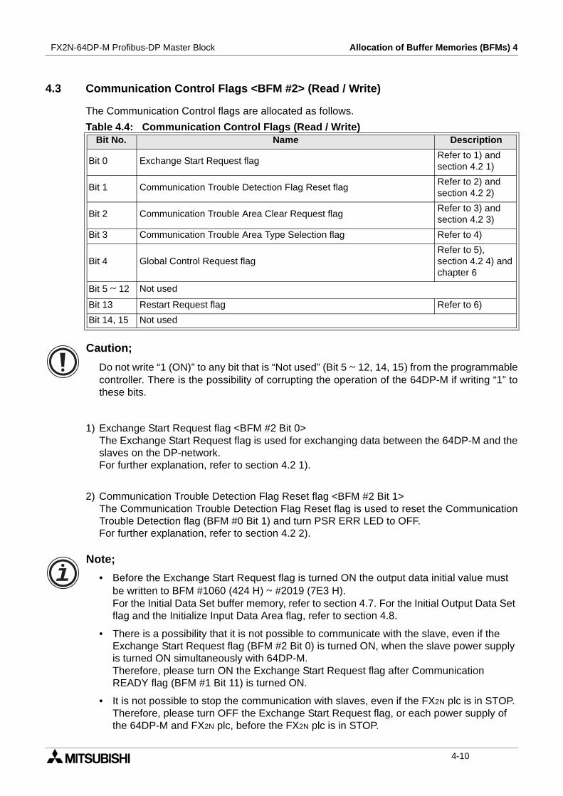
4.3 Communication Control Flags <BFM #2> (Read / Write)
The Communication Control flags are allocated as follows.
Caution;
Do not write “1 (ON)” to any bit that is “Not used” (Bit 5 ~ 12, 14, 15) from the programmablecontroller. There is the possibility of corrupting the operation of the 64DP-M if writing “1” tothese bits.
1) Exchange Start Request flag <BFM #2 Bit 0>The Exchange Start Request flag is used for exchanging data between the 64DP-M and theslaves on the DP-network.For further explanation, refer to section 4.2 1).
2) Communication Trouble Detection Flag Reset flag <BFM #2 Bit 1>The Communication Trouble Detection Flag Reset flag is used to reset the CommunicationTrouble Detection flag (BFM #0 Bit 1) and turn PSR ERR LED to OFF.For further explanation, refer to section 4.2 2).
Note;
• Before the Exchange Start Request flag is turned ON the output data initial value mustbe written to BFM #1060 (424 H) ~ #2019 (7E3 H).For the Initial Data Set buffer memory, refer to section 4.7. For the Initial Output Data Setflag and the Initialize Input Data Area flag, refer to section 4.8.
• There is a possibility that it is not possible to communicate with the slave, even if theExchange Start Request flag (BFM #2 Bit 0) is turned ON, when the slave power supplyis turned ON simultaneously with 64DP-M.Therefore, please turn ON the Exchange Start Request flag after CommunicationREADY flag (BFM #1 Bit 11) is turned ON.
• It is not possible to stop the communication with slaves, even if the FX2N plc is in STOP.Therefore, please turn OFF the Exchange Start Request flag, or each power supply ofthe 64DP-M and FX2N plc, before the FX2N plc is in STOP.
Table 4.4: Communication Control Flags (Read / Write)Bit No. Name Description
Bit 0 Exchange Start Request flagRefer to 1) andsection 4.2 1)
Bit 1 Communication Trouble Detection Flag Reset flagRefer to 2) andsection 4.2 2)
Bit 2 Communication Trouble Area Clear Request flagRefer to 3) andsection 4.2 3)
Bit 3 Communication Trouble Area Type Selection flag Refer to 4)
Bit 4 Global Control Request flagRefer to 5),section 4.2 4) andchapter 6
Bit 5 ~ 12 Not used
Bit 13 Restart Request flag Refer to 6)
Bit 14, 15 Not used
4-10
FX2N-64DP-M Profibus-DP Master Block Allocation of Buffer Memories (BFMs) 4
3) Communication Trouble Area Clear Request flag <BFM #2 Bit 2>The Communication Trouble Area Clear Request flag is used to clear all of theCommunication Trouble Area (BFM #2140 ~ #2179) and the Expansion CommunicationTrouble Area (BFM #2196 ~ #2210).For further explanation, refer to section 4.2 3).
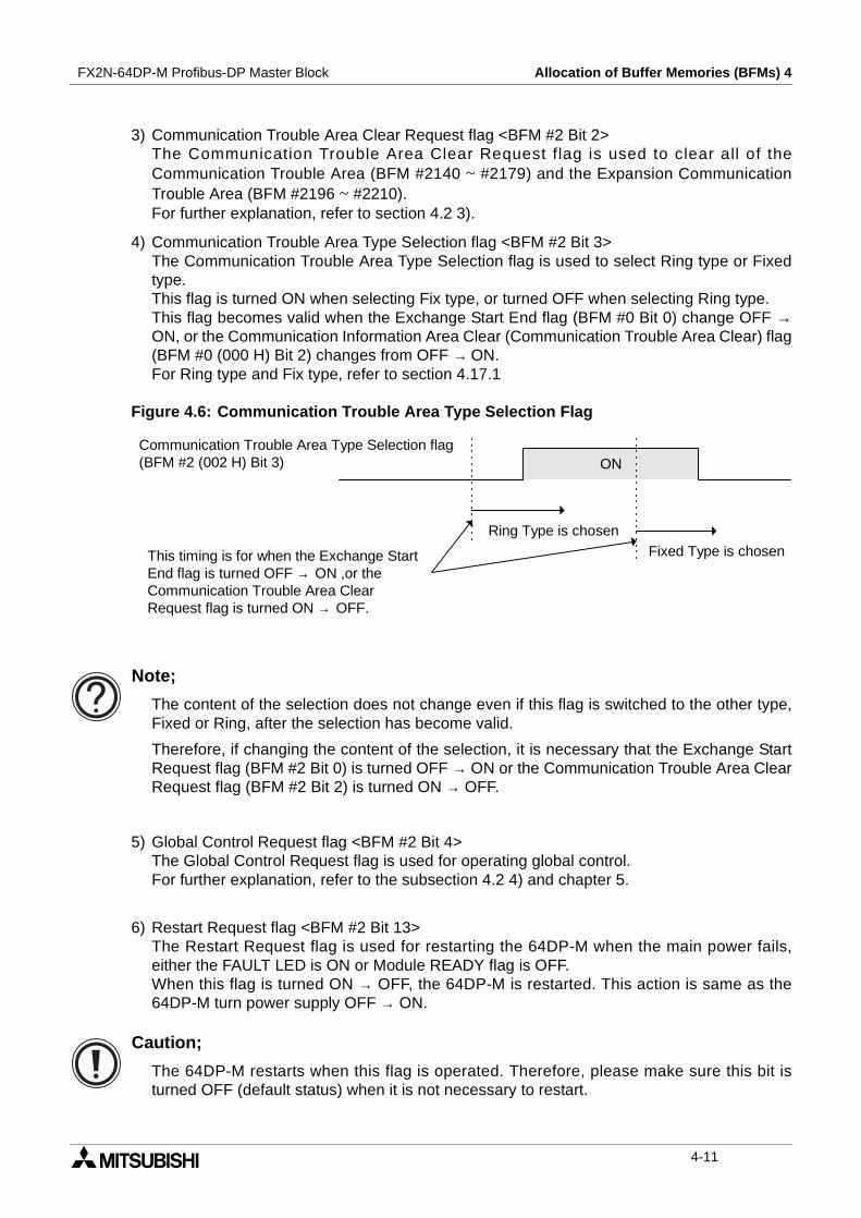
4) Communication Trouble Area Type Selection flag <BFM #2 Bit 3>The Communication Trouble Area Type Selection flag is used to select Ring type or Fixedtype.This flag is turned ON when selecting Fix type, or turned OFF when selecting Ring type.This flag becomes valid when the Exchange Start End flag (BFM #0 Bit 0) change OFF →ON, or the Communication Information Area Clear (Communication Trouble Area Clear) flag(BFM #0 (000 H) Bit 2) changes from OFF → ON.For Ring type and Fix type, refer to section 4.17.1
Figure 4.6: Communication Trouble Area Type Selection Flag
Note;
The content of the selection does not change even if this flag is switched to the other type,Fixed or Ring, after the selection has become valid.
Therefore, if changing the content of the selection, it is necessary that the Exchange StartRequest flag (BFM #2 Bit 0) is turned OFF → ON or the Communication Trouble Area ClearRequest flag (BFM #2 Bit 2) is turned ON → OFF.
5) Global Control Request flag <BFM #2 Bit 4>The Global Control Request flag is used for operating global control.For further explanation, refer to the subsection 4.2 4) and chapter 5.
6) Restart Request flag <BFM #2 Bit 13>The Restart Request flag is used for restarting the 64DP-M when the main power fails,either the FAULT LED is ON or Module READY flag is OFF.When this flag is turned ON → OFF, the 64DP-M is restarted. This action is same as the64DP-M turn power supply OFF → ON.
Caution;
The 64DP-M restarts when this flag is operated. Therefore, please make sure this bit isturned OFF (default status) when it is not necessary to restart.
Communication Trouble Area Type Selection flag(BFM #2 (002 H) Bit 3) ON
Ring Type is chosenFixed Type is chosenThis timing is for when the Exchange Start
End flag is turned OFF → ON ,or theCommunication Trouble Area ClearRequest flag is turned ON → OFF.
4-11
FX2N-64DP-M Profibus-DP Master Block Allocation of Buffer Memories (BFMs) 4
4.4 Communication Stop Timer Setting <BFM #9> (Read / Write)
The communication stop timer is adjusted in 10 ms steps. Default value is 50 (50 × 10 ms =500 ms). When this value is 0, the setting of the communication stop timer assumes it isdefault value. The setting range is 0 and 10 ~ 6,000.
When FROM / TO instructions do not access any buffer memories, the communication timerbegins operating.
Note;
When restarting the communication between the 64DP-M and slaves on the DP-network,do in the following process.
1) Write new values of communication stop timer to the Communication Stop Timer Setting(BFM #9). The FROM / TO Error flag (BFM #29 Bit 9) is turned OFF.
2) Write initial or new output data to the Output Data Area (BFM #1060 ~ #2019), as thecontents of the Output Data Area is held when the FROM / TO Error occurs.
3) Turn OFF to ON the Exchange Start Request flag (BFM #2 Bit 0). The 64DP-M will start tocommunicate to the slaves on the DP-network.
Caution;
If the communication timer reaches it is set time (BFM #9 × 10 ms), the 64DP-Mexperiences a communication time out. At this time, The FROM / TO Error flag (BFM #29 Bit9) is turned ON, and data will not be exchanged with slaves on the DP-network. TheExchange Start Request flag (BFM #2 Bit 0) will turn OFF.
4-12

FX2N-64DP-M Profibus-DP Master Block Allocation of Buffer Memories (BFMs) 4
4.5 Slave Data Consistency Mode <BFM #10 ~ #22>
BFM #10 is used for the selection of Slave Data Consistency Mode. This mode is used tocontrol the storage of data written in the output data area (BFM #1060 ~ #2019) in the sendbuffer.This mode is used to control output data is controlled. Output Data Send Request flags andSending End flags are used in each slave. For details on the Slave Data Consistency Moderefer to subsection 4.5.1. For allocation of Output Data Send Request flags refer to subsection4.5.2. For allocation of Output Data Sending End flags refer to subsection 4.5.3.
Note:
When 64DP-M is exchanging data to the slaves, an error will result if the mode is changed.When changing this mode, the Exchange Start End flag (BFM #0 bit 0) has to be OFF andthe Exchange Start Request flag (BFM #2 bit 0) is turned OFF.
Figure 4.7: Input/Output Data Areas and Receive/Send Buffers
Note:
In the update of the data between 64DP-M and the slave, the data consistency can usuallybe kept to only the units of a single word. Therefore, 64DP-M has Slave Data ConsistencyMode and Global Control Function. Refer to the table below for consistency of sending/receiving data and the relation of each function.
Table 4.5: Slave Data Consistency Mode <BFM #10> (Read / Write)Value Description
K0 Slave Data Consistency Mode disabled.
Other (≠ K0) Slave Data Consistency Mode enabled.
Table 4.6: Consistency of Exchanged DataUsing Function
Sending Data(To Slave)
Receiving Data(From Slave)Using Slave Data Consis-
tency ModeUsing Global Control
Function
Single word data
Multiple word data Single word data
Slave dataconsistency
Slave dataconsistency
Single word dataSlave dataconsistency
64DP-M
Input Data Area(BFM #100 ~ #1059)
Output Data Area(BFM #1060 ~ #2019)
ReceiveBuffer
SendBuffer
DP-Slave
This process can be controlled by the userprogram in Slave Data Consistency Mode.
This process can be controlled by the user programwith the Global Control Function.
4-13
FX2N-64DP-M Profibus-DP Master Block Allocation of Buffer Memories (BFMs) 4
4.5.1 Slave Data Consistency Mode Process
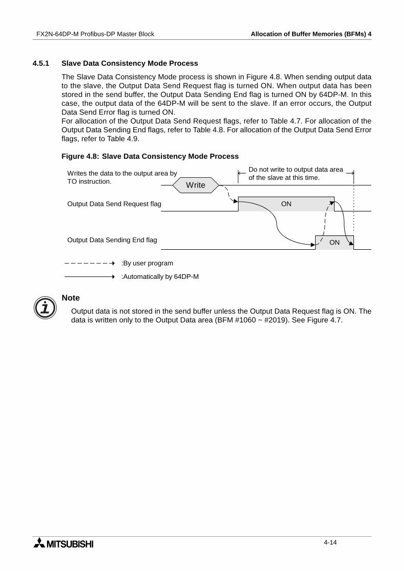
The Slave Data Consistency Mode process is shown in Figure 4.8. When sending output datato the slave, the Output Data Send Request flag is turned ON. When output data has beenstored in the send buffer, the Output Data Sending End flag is turned ON by 64DP-M. In thiscase, the output data of the 64DP-M will be sent to the slave. If an error occurs, the OutputData Send Error flag is turned ON.For allocation of the Output Data Send Request flags, refer to Table 4.7. For allocation of theOutput Data Sending End flags, refer to Table 4.8. For allocation of the Output Data Send Errorflags, refer to Table 4.9.
Figure 4.8: Slave Data Consistency Mode Process
Note
Output data is not stored in the send buffer unless the Output Data Request flag is ON. Thedata is written only to the Output Data area (BFM #1060 ~ #2019). See Figure 4.7.
Do not write to output data areaof the slave at this time.
Output Data Send Request flag
Output Data Sending End flag ON
ON
:By user program
:Automatically by 64DP-M
Write
Writes the data to the output area byTO instruction.
4-14
FX2N-64DP-M Profibus-DP Master Block Allocation of Buffer Memories (BFMs) 4
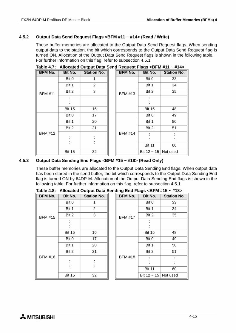
4.5.2 Output Data Send Request Flags <BFM #11 ~ #14> (Read / Write)
These buffer memories are allocated to the Output Data Send Request flags. When sendingoutput data to the station, the bit which corresponds to the Output Data Send Request flag isturned ON. Allocation of the Output Data Send Request flags is shown in the following table.For further information on this flag, refer to subsection 4.5.1
4.5.3 Output Data Sending End Flags <BFM #15 ~ #18> (Read Only)
These buffer memories are allocated to the Output Data Sending End flags. When output datahas been stored in the send buffer, the bit which corresponds to the Output Data Sending Endflag is turned ON by 64DP-M. Allocation of the Output Data Sending End flags is shown in thefollowing table. For further information on this flag, refer to subsection 4.5.1.
Table 4.7: Allocated Output Data Send Request Flags <BFM #11 ~ #14>BFM No. Bit No. Station No. BFM No. Bit No. Station No.
BFM #11
Bit 0 1
BFM #13
Bit 0 33
Bit 1 2 Bit 1 34
Bit 2 3 Bit 2 35
::
::
Bit 15 16 Bit 15 48
BFM #12
Bit 0 17
BFM #14
Bit 0 49
Bit 1 20 Bit 1 50
Bit 2 21 Bit 2 51
::
::
::
::
Bit 11 60
Bit 15 32 Bit 12 ~ 15 Not used
Table 4.8: Allocated Output Data Sending End Flags <BFM #15 ~ #18>BFM No. Bit No. Station No. BFM No. Bit No. Station No.
BFM #15
Bit 0 1
BFM #17
Bit 0 33
Bit 1 2 Bit 1 34
Bit 2 3 Bit 2 35
::
::
Bit 15 16 Bit 15 48
BFM #16
Bit 0 17
BFM #18
Bit 0 49
Bit 1 20 Bit 1 50
Bit 2 21 Bit 2 51
::
::
::
::
Bit 11 60
Bit 15 32 Bit 12 ~ 15 Not used
4-15
FX2N-64DP-M Profibus-DP Master Block Allocation of Buffer Memories (BFMs) 4
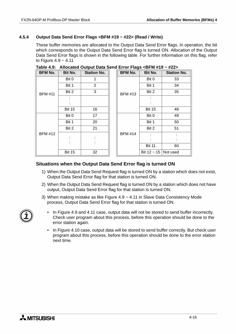
4.5.4 Output Data Send Error Flags <BFM #19 ~ #22> (Read / Write)
These buffer memories are allocated to the Output Data Send Error flags. In operation, the bitwhich corresponds to the Output Data Send Error flag is turned ON. Allocation of the OutputData Send Error flags is shown in the following table. For further information on this flag, referto Figure 4.9 ~ 4.11
Situations when the Output Data Send Error flag is turned ON
1) When the Output Data Send Request flag is turned ON by a station which does not exist,Output Data Send Error flag for that station is turned ON.
2) When the Output Data Send Request flag is turned ON by a station which does not haveoutput, Output Data Send Error flag for that station is turned ON.
3) When making mistake as like Figure 4.9 ~ 4.11 in Slave Data Consistency Modeprocess, Output Data Send Error flag for that station is turned ON.
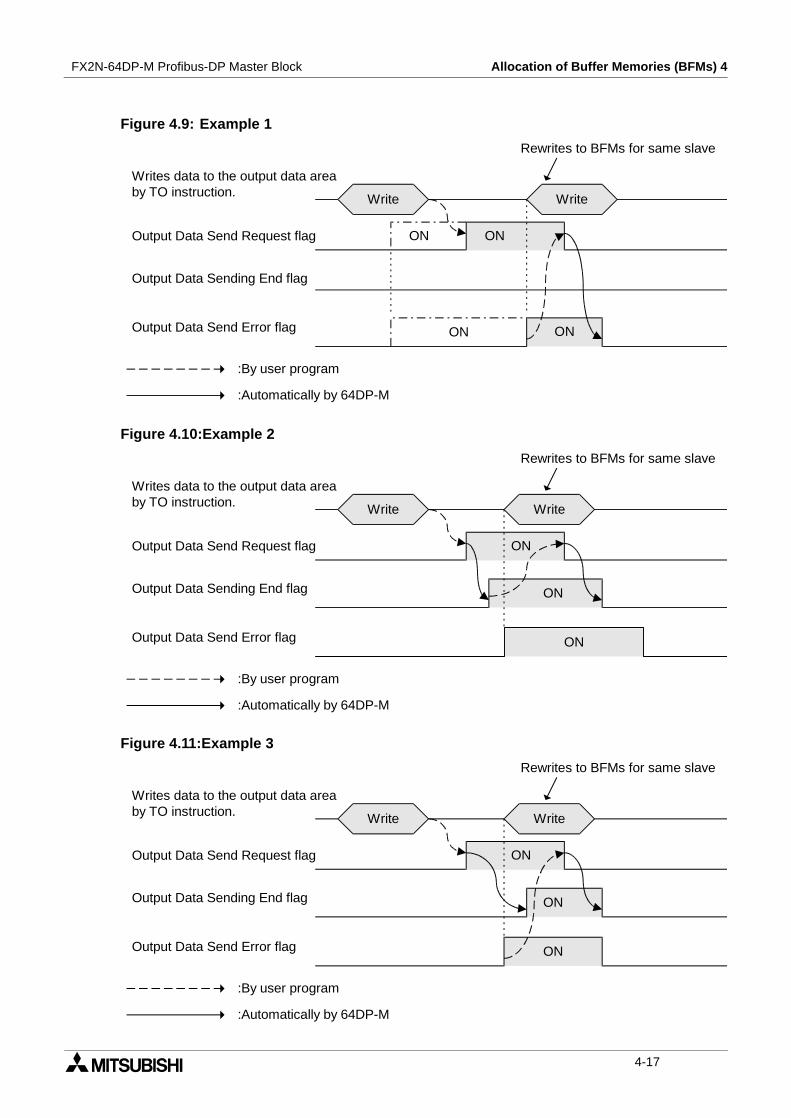
• In Figure 4.9 and 4.11 case, output data will not be stored to send buffer incorrectly.Check user program about this process, before this operation should be done to theerror station again.
• In Figure 4.10 case, output data will be stored to send buffer correctly. But check userprogram about this process, before this operation should be done to the error stationnext time.
Table 4.9: Allocated Output Data Send Error Flags <BFM #19 ~ #22>BFM No. Bit No. Station No. BFM No. Bit No. Station No.
BFM #11
Bit 0 1
BFM #13
Bit 0 33
Bit 1 2 Bit 1 34
Bit 2 3 Bit 2 35
::
::
Bit 15 16 Bit 15 48
BFM #12
Bit 0 17
BFM #14
Bit 0 49
Bit 1 20 Bit 1 50
Bit 2 21 Bit 2 51
::
::
::
::
Bit 11 60
Bit 15 32 Bit 12 ~ 15 Not used
4-16
FX2N-64DP-M Profibus-DP Master Block Allocation of Buffer Memories (BFMs) 4
Figure 4.9: Example 1
Figure 4.10:Example 2
Figure 4.11:Example 3
Output Data Send Request flag ON
:By user program
:Automatically by 64DP-M
Write
Writes data to the output data areaby TO instruction.
Output Data Send Error flag
Write
ON
Rewrites to BFMs for same slave
Output Data Sending End flag
ON
ON
ON
Output Data Send Request flag ON
:By user program
:Automatically by 64DP-M
Write
Writes data to the output data areaby TO instruction.
Output Data Send Error flag
Write
ON
Rewrites to BFMs for same slave
Output Data Sending End flag
ON
Output Data Send Request flag ON
:By user program
:Automatically by 64DP-M
Write
Writes data to the output data areaby TO instruction.
Output Data Send Error flag
Write
ON
Rewrites to BFMs for same slave
Output Data Sending End flag
4-17

FX2N-64DP-M Profibus-DP Master Block Allocation of Buffer Memories (BFMs) 4
4.6 Master Reset <BFM #27> (Read / Write)
The Master Reset buffer memory is used when changing to the test mode or the parameter setmode. When the value of this buffer memory is “K1”, the 64DP-M can be changed to the testmode or parameter set mode. When the value of this buffer memory is changed to “K0”, the64DP-M will restart.However, interval of 1 second or more is necessary when the Master Reset is changed to “K0”.
When finished in the test mode or parameter mode, reset the power supply for PLC and 64DP-M.
Caution;
• The 64DP-M restarts when the value of this buffer memory changes to “K0”. Therefore,please do not access this buffer memory when it is not necessary to restart or changethe test mode and the parameter set mode.
4.7 Initial Data Set <BFM #28> (Read / Write)
The Initial Data Set buffer memory is used to check that the initial data for output to slaves onthe DP-network has finished to write to the Output Data Area buffer memory (BFM #1060 ~BFM #2019).A value of “1” is written to this BFM when the initial contents of the Output Data Area is for allslaves, after these status flags (BFM #29 Bit 14, 15) are turned ON. When these flags are ON,a value of “0” is written to this BFM and the Exchange Start Request flag (BFM #2 Bit 0) isturned ON. At this time, the Exchange Status Request flags are turned OFF.For status flags (BFM #29 Bit 14, 15), refer to section 4.8.
Caution;
This process is necessary for the 64DP-M to communicate correctly with the slaves on theDP-network.If the Exchange Start Request flag is turned ON before the initial data is prepared in the64DP-M, it will communicate incorrectly with slaves on the DP-network.
Table 4.10: Master ResetValue Description
K1 → K064DP-M will restart. Do not access 64DP-M for 1 second by FROM/TOinstruction at when 64DP-M is restarting.
K0 → K164DP-M stop to access Profibus-DP system.An interval of 1 second or more is necessary when the Master Reset ischanged to “K0”.
4-18

FX2N-64DP-M Profibus-DP Master Block Allocation of Buffer Memories (BFMs) 4
4.8 Master Status <BFM #29> (Read Only)
The Master Status buffer memory is allocated as shown on the following table.
4.9 Module ID code <BFM #30> (Read Only)
The identification code for a 64DP-M is available using a FROM instruction. The identificationcode for the 64DP-M is K7060. By reading this identification code, the user may create built-inchecking routines to check whether the physical position of 64DP-M matches the software.
4.10 Number of Used Input Byte <BFM #37> (Read Only)
This buffer memory is used to check the 64DP-M for the number of bytes used in the input dataarea. This value may be more than the value of the configuration software. As the occupiednumber of bytes is included in this value.
4.11 Number of Allocated Slave <BFM #38> (Read Only)
This buffer memory is used to check the number of slaves connected to the 64DP-M. Thisvalue is same as the number of slaves in the configuration software.
4.12 Operation Service Mode <BFM #39> (Read Only)
This buffer memory is used to check the operation service mode of the 64DO-M.
Table 4.11: Master Status <BFM #29 (01D H)>Bit No. Name Description
Bit 0 Master Reset Status flagON when the value of the Master Reset buffer memory(BFM #27) is “1”.
Bit 1 ~ 7 Not used
Bit 8 BFM Access Error flag ON when accessing the buffer memory of “Not used”.
Bit 9Communication Stop TimerTimed Up flag
ON when the Communication Stop Timer is timed up.
Bit 10 ~ 11 Not used
Bit 12Writing Communication ControlStatus flag
ON when writing to the Communication Control flagsbuffer memory (BFM #2) by TO instruction. This flag usesan interlock for exclusive assessing to theCommunication Control flags buffer memory.
Bit 13 Not used
Bit 14 Initial Output Data Set flagON when the 64DP-M finishes to set initial data for outputof the slaves. OFF when writing “0” to the Initial Data Setbuffer memory (BFM #28).
Bit 15 Initialize Input Data Area flagON when the 64DP-M finishes to initialize data for inputof the slaves. OFF when writing “0” to the Initial Data Setbuffer memory (BFM #28).
Table 4.12: Operation Service ModeValue (Hex) Description
0 64DP-M is in normal service mode.
E 64DP-M is in extended service mode.
Other value Configuration error will be occurred in 64DP-M.
4-19

FX2N-64DP-M Profibus-DP Master Block Allocation of Buffer Memories (BFMs) 4
4.13 Input Slave State <BFM #40 ~ #43> (Read Only)
These buffer memories are allocated to the input slave state. When the 64DP-M already hasan input slave, the bit which corresponds to the input slave state is turned ON. Allocation of theinput slave is shown in the following table.
4.14 Output Slave State <BFM #44 ~ #47> (Read Only)
These buffer memories are allocated to the output slave state. When the 64DP-M already hasan output slave, the bit which corresponds to the output slave state is turned ON. Allocation ofthe output slave is shown in the following table.
Table 4.13: Allocated Input SlaveBFM No. Bit No. Slave No. BFM No. Bit No. Slave No.
BFM #40
Bit 0 1
BFM #42
Bit 0 33
Bit 1 2 Bit 1 34
Bit 2 3 Bit 2 35
::
::
Bit 15 16 Bit 15 48
BFM #41
Bit 0 17
BFM #43
Bit 0 49
Bit 1 18 Bit 1 50
Bit 2 19 Bit 2 51
::
::
::
::
Bit 11 60
Bit 15 32 Bit 12 ~ 15 Not used
Table 4.14: Allocated Output SlaveBFM No. Bit No. Slave No. BFM No. Bit No. Slave No.
BFM #44
Bit 0 1
BFM #46
Bit 0 33
Bit 1 2 Bit 1 34
Bit 2 3 Bit 2 35
::
::
Bit 15 16 Bit 15 48
BFM #45
Bit 0 17
BFM #47
Bit 0 49
Bit 1 18 Bit 1 50
Bit 2 19 Bit 2 51
::
::
::
::
Bit 11 60
Bit 15 32 Bit 12 ~ 15 Not used
4-20
FX2N-64DP-M Profibus-DP Master Block Allocation of Buffer Memories (BFMs) 4
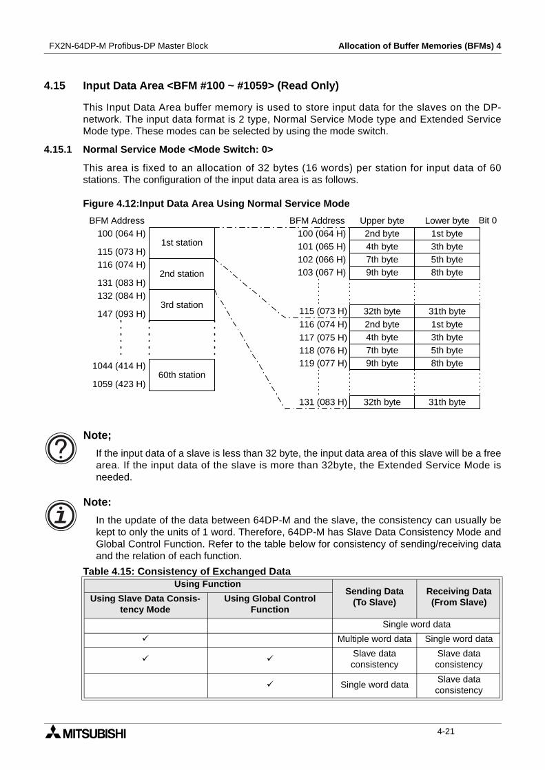
4.15 Input Data Area <BFM #100 ~ #1059> (Read Only)
This Input Data Area buffer memory is used to store input data for the slaves on the DP-network. The input data format is 2 type, Normal Service Mode type and Extended ServiceMode type. These modes can be selected by using the mode switch.
4.15.1 Normal Service Mode <Mode Switch: 0>
This area is fixed to an allocation of 32 bytes (16 words) per station for input data of 60stations. The configuration of the input data area is as follows.
Figure 4.12:Input Data Area Using Normal Service Mode
Note;
If the input data of a slave is less than 32 byte, the input data area of this slave will be a freearea. If the input data of the slave is more than 32byte, the Extended Service Mode isneeded.
Note:
In the update of the data between 64DP-M and the slave, the consistency can usually bekept to only the units of 1 word. Therefore, 64DP-M has Slave Data Consistency Mode andGlobal Control Function. Refer to the table below for consistency of sending/receiving dataand the relation of each function.
Table 4.15: Consistency of Exchanged DataUsing Function
Sending Data(To Slave)
Receiving Data(From Slave)Using Slave Data Consis-
tency ModeUsing Global Control
Function
Single word data
Multiple word data Single word data
Slave dataconsistency
Slave dataconsistency
Single word dataSlave dataconsistency
2nd station
1st station
3rd station
60th station
100 (064 H)
115 (073 H)116 (074 H)
131 (083 H)132 (084 H)
147 (093 H)
1044 (414 H)
1059 (423 H)
2nd byte 1st byte
Bit 0BFM Address BFM Address100 (064 H)
4th byte 3th byte101 (065 H)7th byte 5th byte102 (066 H)9th byte 8th byte103 (067 H)
32th byte 31th byte115 (073 H)
116 (074 H)
117 (075 H)118 (076 H)
131 (083 H)
2nd byte 1st byte4th byte 3th byte7th byte 5th byte9th byte 8th byte
32th byte 31th byte
119 (077 H)
Upper byte Lower byte
4-21
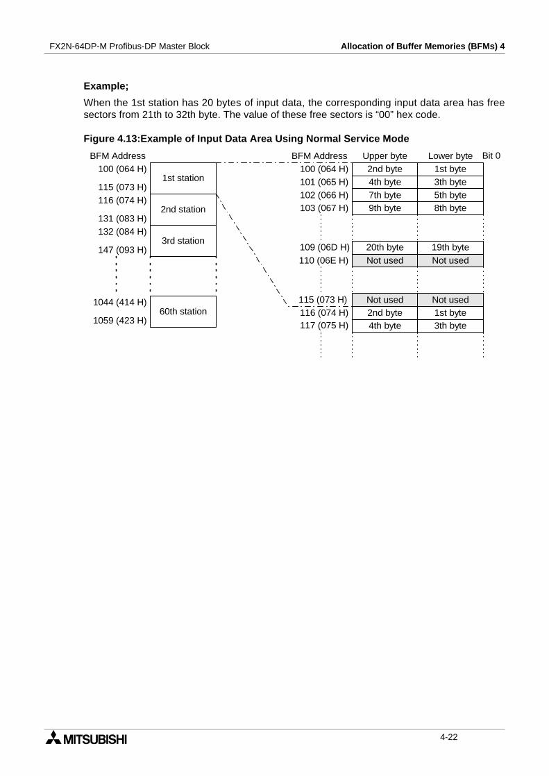
FX2N-64DP-M Profibus-DP Master Block Allocation of Buffer Memories (BFMs) 4
Example;
When the 1st station has 20 bytes of input data, the corresponding input data area has freesectors from 21th to 32th byte. The value of these free sectors is “00” hex code.
Figure 4.13:Example of Input Data Area Using Normal Service Mode
2nd station
1st station
3rd station
60th station
100 (064 H)
115 (073 H)116 (074 H)
131 (083 H)132 (084 H)
147 (093 H)
1044 (414 H)
1059 (423 H)
2nd byte 1st byte
Bit 0BFM Address BFM Address100 (064 H)
4th byte 3th byte101 (065 H)7th byte 5th byte102 (066 H)9th byte 8th byte103 (067 H)
Not used Not used115 (073 H)116 (074 H)117 (075 H)
2nd byte 1st byte4th byte 3th byte
Upper byte Lower byte
20th byte 19th byteNot used Not used
109 (06D H)110 (06E H)
4-22

FX2N-64DP-M Profibus-DP Master Block Allocation of Buffer Memories (BFMs) 4
4.15.2 Extended Service Mode <Mode Switch: E>
This area is assigned in variable length according to the parameter file set in the configurationsoftware (ProfiMap). The data length can be set in the range of 0 ~ 244 bytes. The number ofstations that can be set will vary in the range of 1 ~ 60. However, this Input Data Area is 1920bytes (32 bytes × 60 stations = 1920 bytes) for all slaves.
Example;
An example is shown below where the input data length of the 1st station is 23 bytes and theinput data length of the 2nd station is 7 bytes. The value of this free area is “00” hex code.
Figure 4.14:Example of Input Data Area Using Extended Service Mode
Note;
• When the data length is an odd number of bytes, the last upper byte becomes a freearea as the 1st byte of station data needs to be assigned as a lower byte, and data forthe next station is assigned from the next address.
• When the data length is 0 byte, the input data area for this station will be not be in theInput Data Area buffer memory.
2nd station
1st station
3rd station
100 (064 H)
111 (06F H)112 (070 H)
115 (073 H)116 (074 H)
2nd byte 1st byte
Bit 0BFM Address BFM Address100 (064 H)
4th byte 3th byte101 (065 H)6th byte 5th byte102 (066 H)8th byte 7th byte103 (067 H)
113 (071 H)114 (072 H)
2nd byte 1st byte4th byte 3rd byte
Upper byte Lower byte
23th byteNot used111 (06F H)112 (070 H)
116 (074 H)115 (073 H)
6th byte 5th byteNot used 7th byte2nd byte 1st byte
4-23
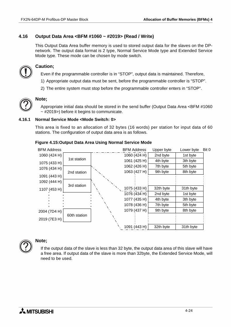
FX2N-64DP-M Profibus-DP Master Block Allocation of Buffer Memories (BFMs) 4
4.16 Output Data Area <BFM #1060 ~ #2019> (Read / Write)
This Output Data Area buffer memory is used to stored output data for the slaves on the DP-network. The output data format is 2 type, Normal Service Mode type and Extended ServiceMode type. These mode can be chosen by mode switch.
Caution;
Even if the programmable controller is in “STOP”, output data is maintained. Therefore,
1) Appropriate output data must be sent, before the programmable controller is “STOP”.
2) The entire system must stop before the programmable controller enters in “STOP”.
Note;
Appropriate initial data should be stored in the send buffer (Output Data Area <BFM #1060~ #2019>) before it begins to communicate.
4.16.1 Normal Service Mode <Mode Switch: 0>
This area is fixed to an allocation of 32 bytes (16 words) per station for input data of 60stations. The configuration of output data area is as follows.
Figure 4.15:Output Data Area Using Normal Service Mode
Note;
If the output data of the slave is less than 32 byte, the output data area of this slave will havea free area. If output data of the slave is more than 32byte, the Extended Service Mode, willneed to be used.
2nd station
1st station
3rd station
60th station
1060 (424 H)
1075 (433 H)1076 (434 H)
1091 (443 H)1092 (444 H)
1107 (453 H)
2004 (7D4 H)
2019 (7E3 H)
2nd byte 1st byte
Bit 0BFM Address BFM Address1060 (424 H)
4th byte 3th byte1061 (425 H)7th byte 5th byte1062 (426 H)9th byte 8th byte1063 (427 H)
32th byte 31th byte1075 (433 H)1076 (434 H)1077 (435 H)1078 (436 H)
1091 (443 H)
2nd byte 1st byte4th byte 3th byte7th byte 5th byte9th byte 8th byte
32th byte 31th byte
1079 (437 H)
Upper byte Lower byte
4-24
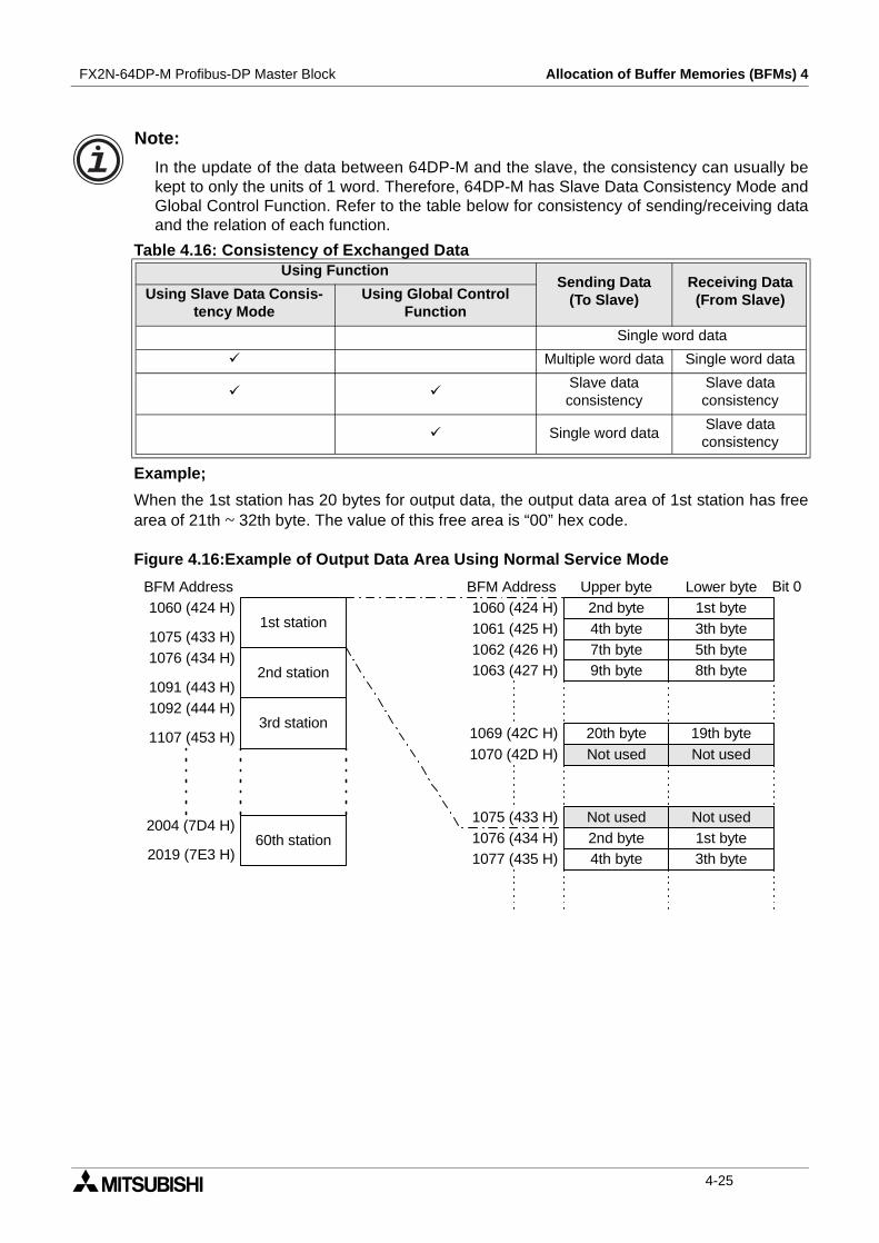
FX2N-64DP-M Profibus-DP Master Block Allocation of Buffer Memories (BFMs) 4
Note:
In the update of the data between 64DP-M and the slave, the consistency can usually bekept to only the units of 1 word. Therefore, 64DP-M has Slave Data Consistency Mode andGlobal Control Function. Refer to the table below for consistency of sending/receiving dataand the relation of each function.
Example;
When the 1st station has 20 bytes for output data, the output data area of 1st station has freearea of 21th ~ 32th byte. The value of this free area is “00” hex code.
Figure 4.16:Example of Output Data Area Using Normal Service Mode
Table 4.16: Consistency of Exchanged DataUsing Function
Sending Data(To Slave)
Receiving Data(From Slave)Using Slave Data Consis-
tency ModeUsing Global Control
Function
Single word data
Multiple word data Single word data
Slave dataconsistency
Slave dataconsistency
Single word dataSlave dataconsistency
2nd station
1st station
3rd station
60th station
2nd byte 1st byte
Bit 0BFM Address BFM Address
4th byte 3th byte7th byte 5th byte9th byte 8th byte
Not used Not used2nd byte 1st byte4th byte 3th byte
Upper byte Lower byte
20th byte 19th byteNot used Not used
1069 (42C H)1070 (42D H)
1060 (424 H)
1075 (433 H)1076 (434 H)
1091 (443 H)1092 (444 H)
1107 (453 H)
2004 (7D4 H)
2019 (7E3 H)
1060 (424 H)1061 (425 H)1062 (426 H)1063 (427 H)
1075 (433 H)1076 (434 H)1077 (435 H)
4-25
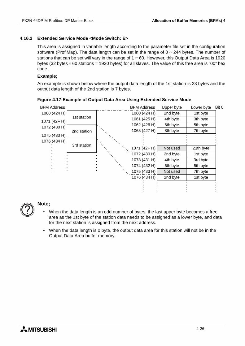
FX2N-64DP-M Profibus-DP Master Block Allocation of Buffer Memories (BFMs) 4
4.16.2 Extended Service Mode <Mode Switch: E>
This area is assigned in variable length according to the parameter file set in the configurationsoftware (ProfiMap). The data length can be set in the range of 0 ~ 244 bytes. The number ofstations that can be set will vary in the range of 1 ~ 60. However, this Output Data Area is 1920bytes (32 bytes × 60 stations = 1920 bytes) for all slaves. The value of this free area is “00” hexcode.
Example;
An example is shown below where the output data length of the 1st station is 23 bytes and theoutput data length of the 2nd station is 7 bytes.
Figure 4.17:Example of Output Data Area Using Extended Service Mode
Note;
• When the data length is an odd number of bytes, the last upper byte becomes a freearea as the 1st byte of the station data needs to be assigned as a lower byte, and datafor the next station is assigned from the next address.
• When the data length is 0 byte, the output data area for this station will not be in theOutput Data Area buffer memory.
2nd station
1st station
3rd station
1060 (424 H) 2nd byte 1st byte
Bit 0BFM Address BFM Address1060 (424 H)
4th byte 3th byte1061 (425 H)6th byte 5th byte1062 (426 H)8th byte 7th byte1063 (427 H)
1073 (431 H)1074 (432 H)
2nd byte 1st byte4th byte 3rd byte
Upper byte Lower byte
23th byteNot used1071 (42F H)1072 (430 H)
1076 (434 H)1075 (433 H)
6th byte 5th byteNot used 7th byte2nd byte 1st byte
1071 (42F H)
1076 (434 H)1075 (433 H)
1072 (430 H)
4-26
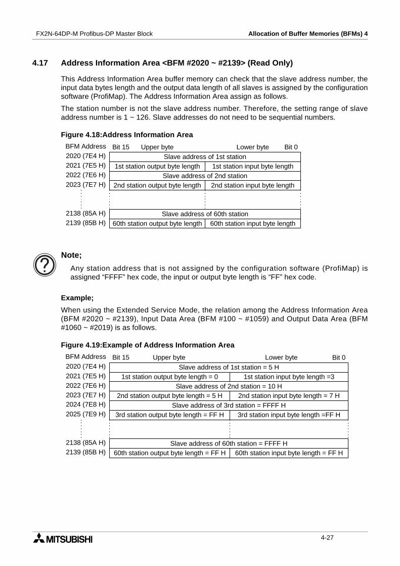
FX2N-64DP-M Profibus-DP Master Block Allocation of Buffer Memories (BFMs) 4
4.17 Address Information Area <BFM #2020 ~ #2139> (Read Only)
This Address Information Area buffer memory can check that the slave address number, theinput data bytes length and the output data length of all slaves is assigned by the configurationsoftware (ProfiMap). The Address Information Area assign as follows.
The station number is not the slave address number. Therefore, the setting range of slaveaddress number is 1 ~ 126. Slave addresses do not need to be sequential numbers.
Figure 4.18:Address Information Area
Note;
Any station address that is not assigned by the configuration software (ProfiMap) isassigned “FFFF” hex code, the input or output byte length is “FF” hex code.
Example;
When using the Extended Service Mode, the relation among the Address Information Area(BFM #2020 ~ #2139), Input Data Area (BFM #100 ~ #1059) and Output Data Area (BFM#1060 ~ #2019) is as follows.
Figure 4.19:Example of Address Information Area
BFM Address2020 (7E4 H)2021 (7E5 H)2022 (7E6 H)
2023 (7E7 H)
2138 (85A H)2139 (85B H)
Slave address of 1st station1st station output byte length 1st station input byte length
Slave address of 2nd station2nd station output byte length 2nd station input byte length
Slave address of 60th station60th station output byte length 60th station input byte length
Upper byte Lower byte Bit 0Bit 15
BFM Address
2020 (7E4 H)
2021 (7E5 H)2022 (7E6 H)2023 (7E7 H)
Slave address of 1st station = 5 H1st station output byte length = 0 1st station input byte length =3
Slave address of 2nd station = 10 H2nd station output byte length = 5 H 2nd station input byte length = 7 H
Upper byte Lower byte Bit 0Bit 15
2024 (7E8 H)
2025 (7E9 H)
2138 (85A H)2139 (85B H)
Slave address of 3rd station = FFFF H3rd station output byte length = FF H 3rd station input byte length =FF H
Slave address of 60th station = FFFF H60th station output byte length = FF H 60th station input byte length = FF H
4-27

FX2N-64DP-M Profibus-DP Master Block Allocation of Buffer Memories (BFMs) 4
Figure 4.20:Input Data Area and Output Data Area
Figure 4.21:System configuration of Example
2nd station
1st station100 (064 H)
101 (065 H)102 (066 H)
105 (069 H)
2nd byte 1st byteBit 0BFM Address BFM Address
100 (064 H)3th byte101 (065 H)
2nd byte 1st byte102 (066 H)4th byte 3rd byte103 (067 H)
Upper byte Lower byte
Not used
6th byte 5th byteNot used 7th byte
2nd station
1st station2nd byte 1st byte1060 (424 H)4th byte 3th byte1061 (425 H)
5th byte1062 (426 H)1063 (427 H)
Not used
Not used
Not used Not used
Not used Not used
Not used
Not usedNot used Not usedNot used Not used
Not used
1059 (423 H)
1064 (428 H)
2019 (7E3 H)
104 (068 H)105 (069 H)106 (06A H)107 (06B H)
This area isnot used inthis system
configuration
106 (06A H)
1059 (423 H)
This area isnot used inthis system
configuration
1060 (424 H)
1062 (426 H)1063 (427 H)
2019 (7E3 H)
This slave doesnot haveoutput.
FX2N-32MR FX2N-64DP-M
Slave Slave
Slave address No.: 10Input data length: 7 bytesOutput data length: 5 bytes
Slave address No.: 5Input data length: 3 bytesOutput data length: 0 bytes
4-28

FX2N-64DP-M Profibus-DP Master Block Allocation of Buffer Memories (BFMs) 4
4.18 Communication Trouble Area <BFM #2140 ~ #2179> (Read Only)
This Communication trouble area can check the Diagnostic Information of a slave when acommunication error occurs on the DP-network (in this case, the Communication TroubleDetection flag (BFM #0 Bit 1) will be ON.). When some kind of error occurs on the DP-network,Diagnostic Information is stored in this area. It contains the Error Code, Detailed Data Lengthand Detailed Data. The method storing is 2 type, Ring Type and Fixed Type. These 2 typescan be chosen by the Communication trouble Area Type Selection flag (BFM #2 Bit 3) turnedON or OFF. When this flag is turned ON, Fixed Type is chosen. When this flag is turned OFF,Ring Type is chosen.
Regardless of the storage method (Fixed Type or Ring Type), up to 8 sets of DiagnosticInformation can be stored in this area. The area can be cleared by turning ON theCommunication Trouble Area Clear Request flag (BFM #2 Bit 2). This area is assigned asfollows.For the Communication Trouble Detection flag, refer to section 4.2. For the CommunicationTrouble Area Clear Request flag, refer to section 4.3.
Figure 4.22:Communication Trouble Area configuration
Informationarea 2
Informationarea 1
Informationarea 3
2140 (85C H) Error code (Refer to subsection 4.17.2.)BFM Address BFM Address
2140 (85C H)Detailed data length (0 ~ 3 H)2141 (85D H)
Detail data 12142 (85E H)Detail data 22143 (85F H)Detail data 32144 (860 H)
2144 (860 H)
2150 (866 H)2149 (865 H)
2145 (861 H)
Informationarea 82179 (883 H)
2154 (86A H)
2175 (87F H)
4-29

FX2N-64DP-M Profibus-DP Master Block Allocation of Buffer Memories (BFMs) 4
4.18.1 Fixed Type and Ring Type methods
With Fixed type, when 8 pieces of Diagnostic Information are stored, areas 2 to 8 are fixed, sowhen the next new diagnostic communication occurs only header area 1 is updated. Refer toFigure 4.23.
Ring type is stored in order from the header, with the header always being the last DiagnosticInformation. Refer to Figure 4.24
Figure 4.23:The Fixed Type
*1 This Diagnostic Information is discarded.
Figure 4.24:The Ring Type
*1 This Diagnostic Information is discarded.
Informationarea 2
Informationarea 1
Informationarea 3
Informationarea 8
1stInformation
This area isnot the
DiagnosticInformation
now.
2ndInformation
1stInformation
This area isnot the
DiagnosticInformation
now.
8thInformation
7thInformation
9thInformation*1
7thInformation
1stInformation
2ndInformation
1stInformation
2ndInformation
New Diagnostic Information
8th Information 9th Information1st Information 2nd Information
Informationarea 2
Informationarea 1
Informationarea 3
Informationarea 8
1stInformation
This area isnot the
DiagnosticInformation
now.
2ndInformation
1stInformation
This area isnot the
DiagnosticInformation
now.
8thInformation
7thInformation
9thInformation
8thInformation
1stInformation
2ndInformation
2ndInformation*1
3rdInformation
New Diagnostic Information
8th Information 9th Information1st Information 2nd Information
4-30

FX2N-64DP-M Profibus-DP Master Block Allocation of Buffer Memories (BFMs) 4
4.18.2 Error codes
Error codes are shown in the following table.
1) Error code: 0200 HWhen this error occurs, configuration of the Diagnostic Information assigns following figure4.25.In addition, the Expansion Diagnostic Information is stored in the Expansion communicationTrouble Area <BFM #2196 ~ #2210> for only the latest the Diagnostic Information of theerror code = 0200 H.
Figure 4.25:Configuration of the Diagnostic Information Occurring 0200 H Error Code
*1 The address of the master that controls the slave in which this Diagnostic Informationoccurred is stored.However, FF H is stored when the Diagnostic Information shows that communication tothe slave is failed.
*2 The address of the slave in which this Diagnostic Information occurred is stored.
*3 This diagnostic status is assigned as follows table 4.16.
*4 The NPO ID code of the slave is stored.However, FF H is stored when the Diagnostic Information shows that communication tothe slave is failed.
Table 4.17: Error Codes in the Diagnostic InformationErrorcode
Datalength
Detailed DataCommunication Status Further Information
Data 1 Data 2 Data 3
0200 H 3 Refer to 1) Continues communication Refer to 1)
1121 H 1 03 H - -Stops communication afterthe error occurs.
Refer to 2)
1300 H 2 Refer to 3) - Refer to 3)
3000 H 1 Ignored - - Refer to 4)
Detail Data 3Detail Data 2Detail Data 1
Error Code = 0200 HDetailed data length = 3 H
Master Address *1 (hex code)Diagnostic Status (Refer to Table 4.14.) *3 (hex code)
Slave ID *4 (hex code)
Slave Address *2 (hex code)
4-31

FX2N-64DP-M Profibus-DP Master Block Allocation of Buffer Memories (BFMs) 4
Table 4.18:Diagnostic Bit StatusBitNo.
Name Description and Check pointsSettingStation
Bit 0Parameterallocation request
Master parameter allocation request from slave.This diagnostic information will always occur at exchange start, so itcan be ignored.If this diagnostic information occurs during exchange, check theslave status and communication line.
slave
Bit 1 Slave status errorMaster diagnostic data read request from slave.If this bit is ON, check the slave status.
slave
Bit 2 Not used (This bit is OFF.)
Bit 3 WDT monitoringWatchdog monitoring is being conducted in the slave.(normal operation)
slave
Bit 4 FREEZE mode This slave in FREEZE mode. (normal operation) slave
Bit 5 SYNC mode This slave in SYNC mode. (normal operation) slave
Bit 6 Not used (This bit is OFF.)
Bit 7The cycliccommunicationstop
The cyclic communication for this module was separated by theparameter setting.This diagnostic information will always occur at exchange start, so itcan be ignored.If this bit is ON, check the parameter on the DP-network waschanged by class 2 master.
Master
Bit 8No comms withslave
Master can not communicate with slave.Check the slave status and communication circuit. And check theparameter.
Master
Bit 9 Slave not readyThe slave is not ready to exchange.This diagnostic status will always occur at exchange start, checkthe slave status and communication circuit.
slave
Bit 10Parametermis-match
The parameter received for byte length of Input/Output from themaster does not match that of the slave.Check the slave parameter.
slave
Bit 11
ExpansionDiagnosticInformationreceived
Expansion Diagnostic Information received. Master
Bit 12Not supportfunction
The function requested by the master is not supported in the slave. slave
Bit 13Incorrect slavedata
Data from the slave is incorrect. Master
Bit 14Incorrectparameter
The parameter transmitted to this slave by the master is incorrect. slave
Bit 15Multiple mastercomms
This slave is controlled by another master. Master
4-32

FX2N-64DP-M Profibus-DP Master Block Allocation of Buffer Memories (BFMs) 4
2) Error code: 1121 HThis error means that the slave address specified in the parameter is the same as that ofthe master.This error occurs immediately after the power supply is turned ON or the 64DP-M is reset.Even though this error is occurring, if the Exchange Start Request (BFM #2 Bit 0) is ONthen error code 3000h will occur, the FAULT LED will turn ON and operation will stop.
Check Point
Check the slave address and master address. If these are same address, set these addresscorrectly.
3) Error code: 1300 HThis error means that no active slaves are set in the parameter. When this error occurs thedetailed data is set number of slaves set in the parameter to the detailed data 1.This error occurs immediately after the power supply is turned ON or the 64DP-M is reset.Even though this error is occurring, if the Exchange Start Request(BFM2:b0) is on thenerror 3000h will occur, the FAULT LED will turn ON, and operation will stop.
Check Points
a) Set 1 or more active slave in the parameter.
b) When the FAULT LED is turned on, reset by turning OFF → ON → OFF the BFM #0 Bit13 for (a) above.
4) Error code: 1302 HThis error means that the capacity of the parameter area is insufficient.This error occurs immediately after the power supply is turned ON or the 64DP-M is reset.When this error has occurred, the FAULT LED will turn ON, and operation will stop.
Check Points
Check capacity of the parameter area and expansion diagnostic information data length.Please, decrease the number of slaves or change slave's type.For expansion diagnostic information data length, refer to the either Note on subsection4.18.1 or Note on subsection 1.3.1.
5) Error code: 3000 HThis error means that 64DP-M had an error code of 1300H or 1121H, or has an unexpectederror.When this error has occurred, the FAULT LED will turn ON, and operation will stop.
Check Points
a) When the above error 1300 H or 1121 H had occurred, refer to the individual error codes(subsection 4.17.3. 2), 3)).
b) OtherwiseAn unexpected error has occurred. In this case, please contact a service representative.
4-33

FX2N-64DP-M Profibus-DP Master Block Allocation of Buffer Memories (BFMs) 4
4.19 Expansion Communication Trouble Area <BFM #2196 ~ #2210> (Read Only)
The Expansion Communication Trouble Area shows only the latest Expansion DiagnosticInformation in error code 0200 H. For Communication Trouble Information Area, refer tosection 4.17. For Error code 0200 H, refer to 4.17.2.
Figure 4.26:Expansion Communication Trouble Area
Communication Trouble Area(Communication Trouble Areachoosing Fixed type.)
7th DiagnosticInformation
data
9th DiagnosticInformation
data
6th DiagnosticInformation
data
2140 (85C H) Expansion Diagnostic Information DataLength
BFM Address BFM Address
2196 (894 H)
Information Data1st Byte
2197 (895 H)
2198 (896 H)
2199 (897 H)
2210 (8A2 H)
2144 (860 H)
2150 (866 H)2149 (865 H)
2145 (861 H)
1st DiagnosticInformation
data2179 (883 H)
2154 (86A H)
2175 (87F H)
Expansion Communication Trouble Area
Latestdata
Information Data2nd Byte
Over 27 Bytes Status(Refer to subsection 4.18.2.
Information Data4th Byte
Information Data3rd Byte
Information Data26th Byte
Information Data25th Byte
Upper Byte Lower Byte
This Information does not have the Expansion Diagnostic Information,when Error Code ≠ 0200 H, or Diagnostic status Bit 11 is OFF when ErrorCode = 0200 H
This Information has the Expansion Diagnostic Information, whenDiagnostic status Bit 11 is ON when Error Code = 0200 H
:
:
4-34
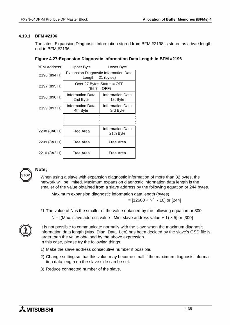
FX2N-64DP-M Profibus-DP Master Block Allocation of Buffer Memories (BFMs) 4
4.19.1 BFM #2196
The latest Expansion Diagnostic Information stored from BFM #2198 is stored as a byte lengthunit in BFM #2196.
Figure 4.27:Expansion Diagnostic Information Data Length in BFM #2196
Note;
When using a slave with expansion diagnostic information of more than 32 bytes, thenetwork will be limited. Maximum expansion diagnostic information data length is thesmaller of the value obtained from a slave address by the following equation or 244 bytes.
Maximum expansion diagnostic information data length (bytes)
= [12600 ÷ N*1 - 10] or [244]
*1 The value of N is the smaller of the value obtained by the following equation or 300.
N = [(Max. slave address value - Min. slave address value + 1) × 5] or [300]
It is not possible to communicate normally with the slave when the maximum diagnosisinformation data length (Max_Diag_Data_Len) has been decided by the slave’s GSD file islarger than the value obtained by the above expression.In this case, please try the following things.
1) Make the slave address consecutive number if possible.
2) Change setting so that this value may become small if the maximum diagnosis informa-tion data length on the slave side can be set.
3) Reduce connected number of the slave.
Expansion Diagnostic Information DataLength = 21 (bytes)
BFM Address
2196 (894 H)
Information Data1st Byte
2197 (895 H)
2198 (896 H)
2199 (897 H)
2210 (8A2 H)
Information Data2nd Byte
Over 27 Bytes Status = OFF(Bit 7 = OFF)
Information Data4th Byte
Information Data3rd Byte
Free Area Free Area
Upper Byte Lower Byte
Free AreaInformation Data
21th Byte
Free Area Free Area
2209 (8A1 H)
2208 (8A0 H)
4-35
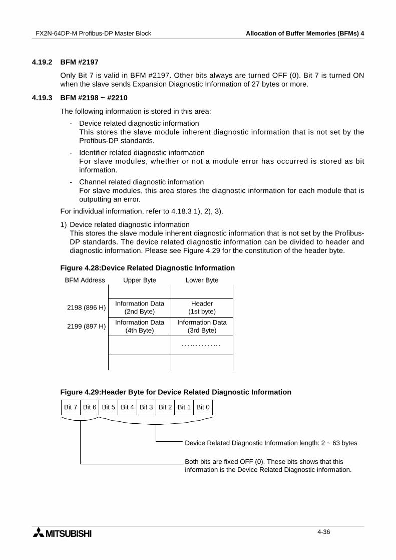
FX2N-64DP-M Profibus-DP Master Block Allocation of Buffer Memories (BFMs) 4
4.19.2 BFM #2197
Only Bit 7 is valid in BFM #2197. Other bits always are turned OFF (0). Bit 7 is turned ONwhen the slave sends Expansion Diagnostic Information of 27 bytes or more.
4.19.3 BFM #2198 ~ #2210
The following information is stored in this area:
- Device related diagnostic informationThis stores the slave module inherent diagnostic information that is not set by theProfibus-DP standards.
- Identifier related diagnostic informationFor slave modules, whether or not a module error has occurred is stored as bitinformation.
- Channel related diagnostic informationFor slave modules, this area stores the diagnostic information for each module that isoutputting an error.
For individual information, refer to 4.18.3 1), 2), 3).
1) Device related diagnostic informationThis stores the slave module inherent diagnostic information that is not set by the Profibus-DP standards. The device related diagnostic information can be divided to header anddiagnostic information. Please see Figure 4.29 for the constitution of the header byte.
Figure 4.28:Device Related Diagnostic Information
Figure 4.29:Header Byte for Device Related Diagnostic Information
BFM Address
Header(1st byte)
2198 (896 H)
2199 (897 H)
Information Data(2nd Byte)
Information Data(4th Byte)
Information Data(3rd Byte)
Upper Byte Lower Byte
Bit 7 Bit 6 Bit 5 Bit 4 Bit 3 Bit 2 Bit 1 Bit 0
Device Related Diagnostic Information length: 2 ~ 63 bytes
Both bits are fixed OFF (0). These bits shows that thisinformation is the Device Related Diagnostic information.
4-36
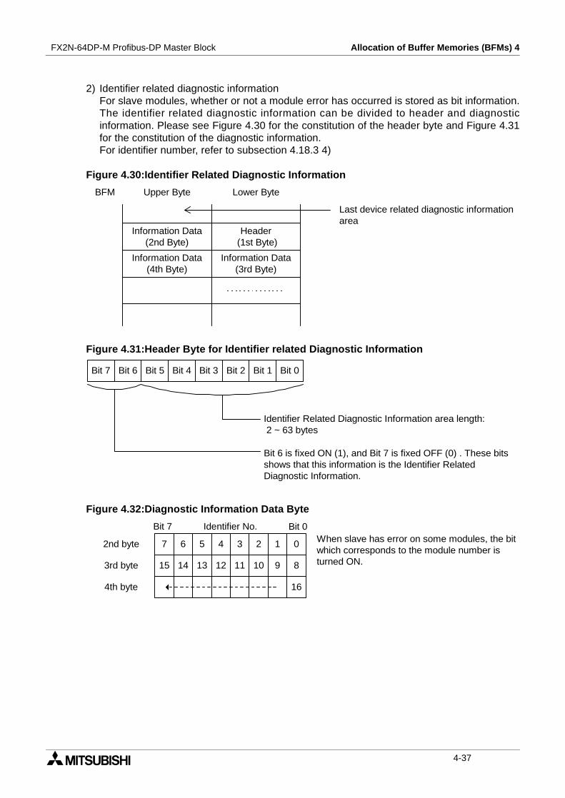
FX2N-64DP-M Profibus-DP Master Block Allocation of Buffer Memories (BFMs) 4
2) Identifier related diagnostic informationFor slave modules, whether or not a module error has occurred is stored as bit information.The identifier related diagnostic information can be divided to header and diagnosticinformation. Please see Figure 4.30 for the constitution of the header byte and Figure 4.31for the constitution of the diagnostic information.For identifier number, refer to subsection 4.18.3 4)
Figure 4.30:Identifier Related Diagnostic Information
Figure 4.31:Header Byte for Identifier related Diagnostic Information
Figure 4.32:Diagnostic Information Data Byte
BFM
Header(1st Byte)
Information Data(2nd Byte)
Information Data(4th Byte)
Information Data(3rd Byte)
Upper Byte Lower Byte
Last device related diagnostic informationarea
Bit 7 Bit 6 Bit 5 Bit 4 Bit 3 Bit 2 Bit 1 Bit 0
Identifier Related Diagnostic Information area length:2 ~ 63 bytes
Bit 6 is fixed ON (1), and Bit 7 is fixed OFF (0) . These bitsshows that this information is the Identifier RelatedDiagnostic Information.
7 6 5 4 3 2 1 0
15 14 13 12 11 10 9 8
16
3rd byte
2nd byte
4th byte
Identifier No. Bit 0Bit 7When slave has error on some modules, the bitwhich corresponds to the module number isturned ON.
4-37
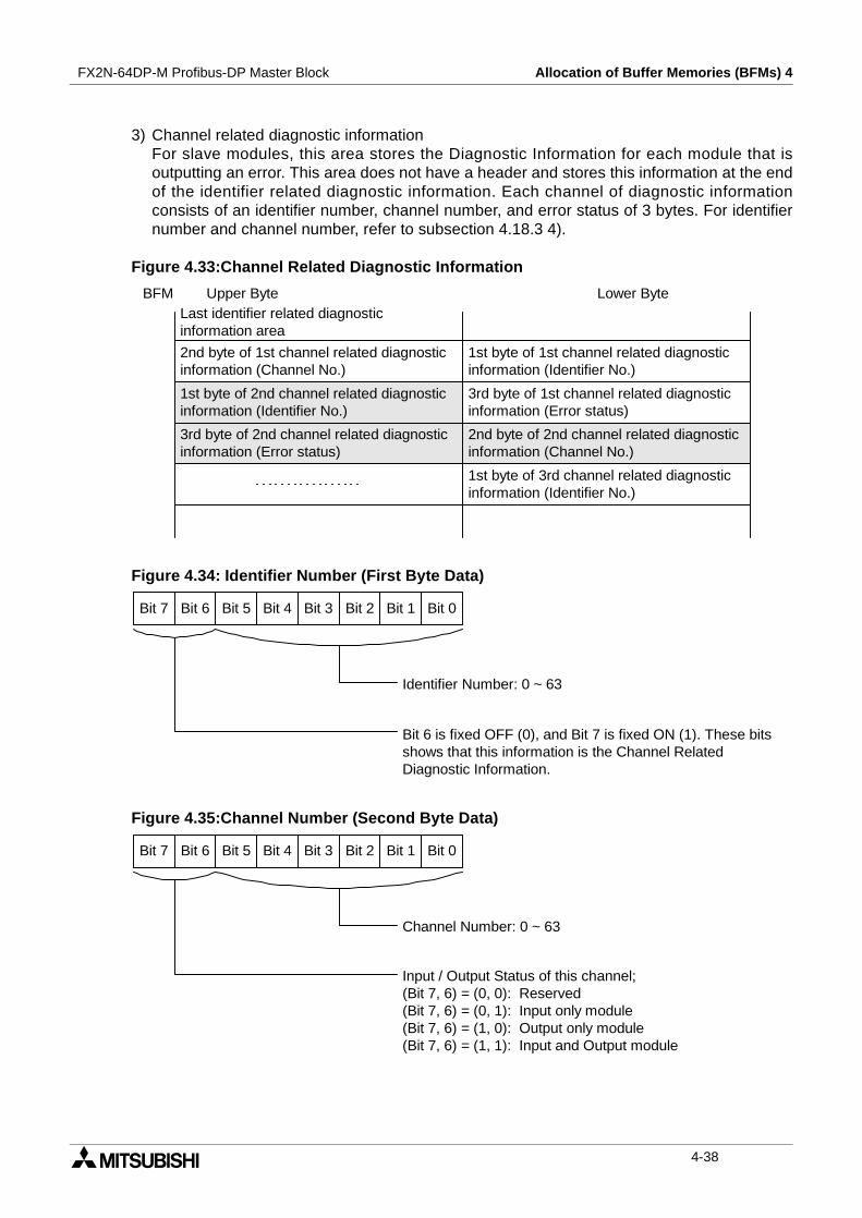
FX2N-64DP-M Profibus-DP Master Block Allocation of Buffer Memories (BFMs) 4
3) Channel related diagnostic informationFor slave modules, this area stores the Diagnostic Information for each module that isoutputting an error. This area does not have a header and stores this information at the endof the identifier related diagnostic information. Each channel of diagnostic informationconsists of an identifier number, channel number, and error status of 3 bytes. For identifiernumber and channel number, refer to subsection 4.18.3 4).
Figure 4.33:Channel Related Diagnostic Information
Figure 4.34: Identifier Number (First Byte Data)
Figure 4.35:Channel Number (Second Byte Data)
1st byte of 1st channel related diagnosticinformation (Identifier No.)
2nd byte of 1st channel related diagnosticinformation (Channel No.)
1st byte of 2nd channel related diagnosticinformation (Identifier No.)
3rd byte of 1st channel related diagnosticinformation (Error status)
Upper Byte Lower Byte
3rd byte of 2nd channel related diagnosticinformation (Error status)
2nd byte of 2nd channel related diagnosticinformation (Channel No.)
Last identifier related diagnosticinformation area
1st byte of 3rd channel related diagnosticinformation (Identifier No.)
BFM
Bit 7 Bit 6 Bit 5 Bit 4 Bit 3 Bit 2 Bit 1 Bit 0
Identifier Number: 0 ~ 63
Bit 6 is fixed OFF (0), and Bit 7 is fixed ON (1). These bitsshows that this information is the Channel RelatedDiagnostic Information.
Bit 7 Bit 6 Bit 5 Bit 4 Bit 3 Bit 2 Bit 1 Bit 0
Channel Number: 0 ~ 63
Input / Output Status of this channel;(Bit 7, 6) = (0, 0): Reserved(Bit 7, 6) = (0, 1): Input only module(Bit 7, 6) = (1, 0): Output only module(Bit 7, 6) = (1, 1): Input and Output module
4-38
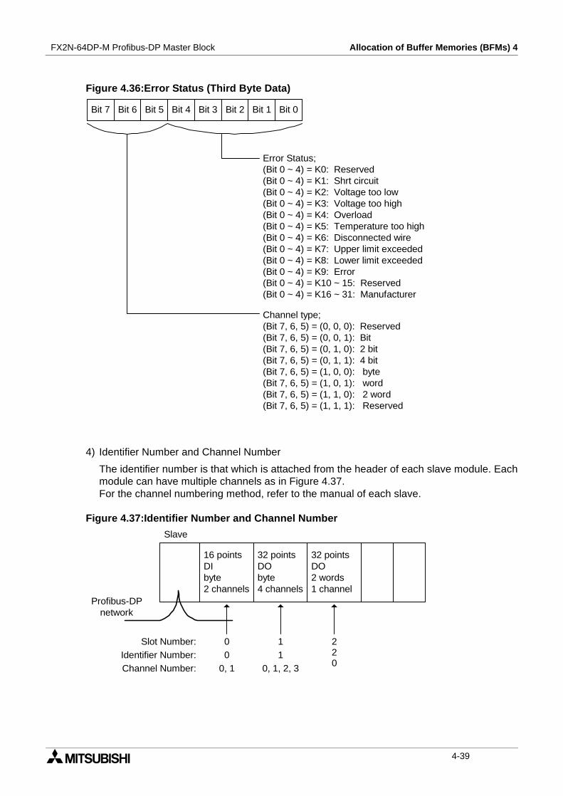
FX2N-64DP-M Profibus-DP Master Block Allocation of Buffer Memories (BFMs) 4
Figure 4.36:Error Status (Third Byte Data)
4) Identifier Number and Channel Number
The identifier number is that which is attached from the header of each slave module. Eachmodule can have multiple channels as in Figure 4.37.For the channel numbering method, refer to the manual of each slave.
Figure 4.37:Identifier Number and Channel Number
Bit 7 Bit 6 Bit 5 Bit 4 Bit 3 Bit 2 Bit 1 Bit 0
Error Status;(Bit 0 ~ 4) = K0: Reserved(Bit 0 ~ 4) = K1: Shrt circuit(Bit 0 ~ 4) = K2: Voltage too low(Bit 0 ~ 4) = K3: Voltage too high(Bit 0 ~ 4) = K4: Overload(Bit 0 ~ 4) = K5: Temperature too high(Bit 0 ~ 4) = K6: Disconnected wire(Bit 0 ~ 4) = K7: Upper limit exceeded(Bit 0 ~ 4) = K8: Lower limit exceeded(Bit 0 ~ 4) = K9: Error(Bit 0 ~ 4) = K10 ~ 15: Reserved(Bit 0 ~ 4) = K16 ~ 31: Manufacturer
Channel type;(Bit 7, 6, 5) = (0, 0, 0): Reserved(Bit 7, 6, 5) = (0, 0, 1): Bit(Bit 7, 6, 5) = (0, 1, 0): 2 bit(Bit 7, 6, 5) = (0, 1, 1): 4 bit(Bit 7, 6, 5) = (1, 0, 0): byte(Bit 7, 6, 5) = (1, 0, 1): word(Bit 7, 6, 5) = (1, 1, 0): 2 word(Bit 7, 6, 5) = (1, 1, 1): Reserved
Slave
Profibus-DPnetwork
16 pointsDIbyte2 channels
32 pointsDObyte4 channels
32 pointsDO2 words1 channel
Slot Number:Identifier Number:Channel Number:
0 10 1
0, 1 0, 1, 2, 3
220
4-39
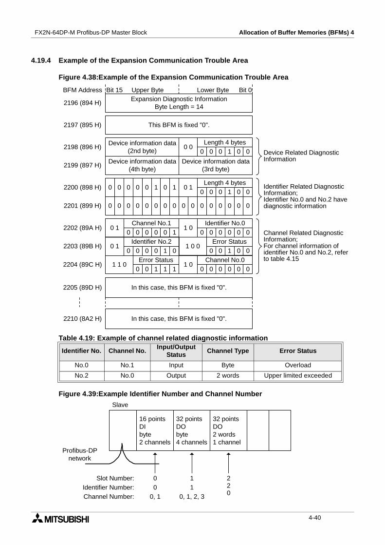
FX2N-64DP-M Profibus-DP Master Block Allocation of Buffer Memories (BFMs) 4
4.19.4 Example of the Expansion Communication Trouble Area
Figure 4.38:Example of the Expansion Communication Trouble Area
Figure 4.39:Example Identifier Number and Channel Number
Table 4.19: Example of channel related diagnostic information
Identifier No. Channel No.Input/Output
StatusChannel Type Error Status
No.0 No.1 Input Byte Overload
No.2 No.0 Output 2 words Upper limited exceeded
2203 (89B H)
Expansion Diagnostic InformationByte Length = 14
BFM Address
This BFM is fixed "0".
Device information data(4th byte)
0 1
0 1
1 1 0
0 0Length 4 bytes
0 1Length 4 bytes
Device information data(2nd byte)
0 1 0 1
Device information data(3rd byte)
Error Status1 0 0
1 0Identifier No.0Channel No.1
Identifier No.2
Channel No.01 0
Error Status
0 0 0 0
0 0 0 0 0 0 0 0 0 0 0 0 0 0 0 0
2196 (894 H)
2197 (895 H)
2198 (896 H)
2199 (897 H)
2200 (898 H)
2201 (899 H)
2202 (89A H)
2204 (89C H)
2205 (89D H)
2210 (8A2 H)
In this case, this BFM is fixed "0".
In this case, this BFM is fixed "0".
0 0 0 1 0 0
0 0 0 1 0 0
0 0 0 0 0 0
0 0 1 0 0
0 0 0 0 0 1
0 0 0 0 1 0
0 0 1 1 1 0 0 0 0 00
Upper Byte Lower Byte Bit 0Bit 15
Device Related DiagnosticInformation
Identifier Related DiagnosticInformation;Identifier No.0 and No.2 havediagnostic information
Channel Related DiagnosticInformation;For channel information ofidentifier No.0 and No.2, referto table 4.15
Slave
Profibus-DPnetwork
16 pointsDIbyte2 channels
32 pointsDObyte4 channels
32 pointsDO2 words1 channel
Slot Number:Identifier Number:Channel Number:
0 10 1
0, 1 0, 1, 2, 3
220
4-40

FX2N-64DP-M Profibus-DP Master Block Allocation of Buffer Memories (BFMs) 4
4.20 Slave Diagnostic Status Cancel <BFM #2180> (Read / Write)
This stores the value that masks the slave Diagnostic status (error code = 0200 H detailed data2). Even if the slave diagnostic status corresponding to this area bit occurs the CommunicationTrouble Detection flag (BFM #0 Bit 1) and RSP ERR LED does not turn ON. In addition, thediagnostic information is not stored in the Communication Trouble Area (BFM #2140 ~ #2179).The default value is 02B9 H.For the Diagnostic Status of further information, refer to 4.17.2.
Note;
This 02B9 H diagnostic information also occurs during normal situation and is masked. Thisvalue can only be changed when Exchange Start Request flag (BFM #2 Bit 0) is OFF. If thisflag is turned ON, changes are ignored.
Figure 4.40:Slave Diagnostic Status Channel Area
Table 4.20: Diagnostic StatusBit No. Name Bit No. Name
0 Parameter allocation request 8 No comms with slave
1 Slave status error 9 Slave not ready
2 Not used (This bit is OFF.) 10 Parameter mis-match
3 WDT monitoring 11Expansion Diagnostic Informationreceived
4 FREEZE mode 12 Not support function
5 SYNC mode 13 Incorrect slave data
6 Not used (This bit is OFF.) 14 Incorrect parameter
7 The cyclic communication stop 15 Multiple master comms
0
Bit15 14
0
13
0
12
0
11
0
10
0
9
1
8
0
7
1
6
0
5
1
4
1
3
1
2
0
1
0 1
Bit0
BFM#2180 (884 H)
9B20 Defaultvalue:
02B9 H
1 The Diagnostic Status of this bit is masked. For the diagnostic Status,refer to table 4.14 or 4.16.
:
4-41
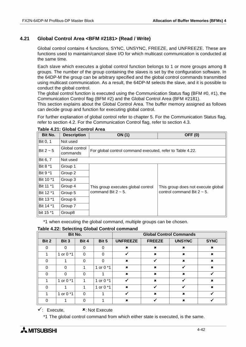
FX2N-64DP-M Profibus-DP Master Block Allocation of Buffer Memories (BFMs) 4
4.21 Global Control Area <BFM #2181> (Read / Write)
Global control contains 4 functions, SYNC, UNSYNC, FREEZE, and UNFREEZE. These arefunctions used to maintain/cancel slave I/O for which multicast communication is conducted atthe same time.
Each slave which executes a global control function belongs to 1 or more groups among 8groups. The number of the group containing the slaves is set by the configuration software. Inthe 64DP-M the group can be arbitrary specified and the global control commands transmittedusing multicast communication. As a result, the 64DP-M selects the slave, and it is possible toconduct the global control.The global control function is executed using the Communication Status flag (BFM #0, #1), theCommunication Control flag (BFM #2) and the Global Control Area (BFM #2181).This section explains about the Global Control Area. The buffer memory assigned as followscan decide group and function for executing global control.
For further explanation of global control refer to chapter 5. For the Communication Status flag,refer to section 4.2. For the Communication Control flag, refer to section 4.3.
*1 when executing the global command, multiple groups can be chosen.
: Execute, : Not Execute
*1 The global control command from which either state is executed, is the same.
Table 4.21: Global Control AreaBit No. Description ON (1) OFF (0)
Bit 0, 1 Not used
Bit 2 ~ 5Global controlcommands
For global control command executed, refer to Table 4.22.
Bit 6, 7 Not used
Bit 8 *1 Group 1
This group executes global controlcommand Bit 2 ~ 5.
This group does not execute globalcontrol command Bit 2 ~ 5.
Bit 9 *1 Group 2
Bit 10 *1 Group 3
Bit 11 *1 Group 4
Bit 12 *1 Group 5
Bit 13 *1 Group 6
Bit 14 *1 Group 7
bit 15 *1 Group8
Table 4.22: Selecting Global Control commandBit No. Global Control Commands
Bit 2 Bit 3 Bit 4 Bit 5 UNFREEZE FREEZE UNSYNC SYNC
0 0 0 0
1 1 or 0 *1 0 0
0 1 0 0
0 0 1 1 or 0 *1
0 0 0 1
1 1 or 0 *1 1 1 or 0 *1
0 1 1 1 or 0 *1
1 1 or 0 *1 0 1
0 1 0 1
4-42
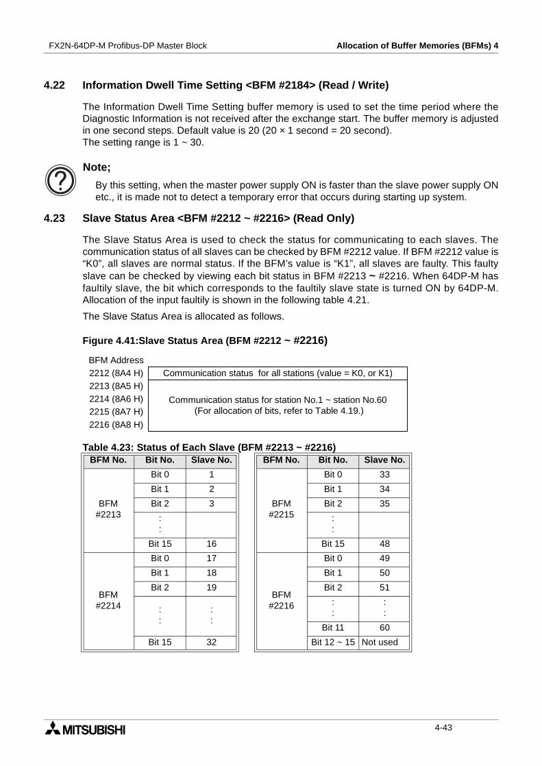
FX2N-64DP-M Profibus-DP Master Block Allocation of Buffer Memories (BFMs) 4
4.22 Information Dwell Time Setting <BFM #2184> (Read / Write)
The Information Dwell Time Setting buffer memory is used to set the time period where theDiagnostic Information is not received after the exchange start. The buffer memory is adjustedin one second steps. Default value is 20 (20 × 1 second = 20 second).The setting range is 1 ~ 30.
Note;
By this setting, when the master power supply ON is faster than the slave power supply ONetc., it is made not to detect a temporary error that occurs during starting up system.
4.23 Slave Status Area <BFM #2212 ~ #2216> (Read Only)
The Slave Status Area is used to check the status for communicating to each slaves. Thecommunication status of all slaves can be checked by BFM #2212 value. If BFM #2212 value is“K0”, all slaves are normal status. If the BFM’s value is “K1”, all slaves are faulty. This faultyslave can be checked by viewing each bit status in BFM #2213 ~ #2216. When 64DP-M hasfaultily slave, the bit which corresponds to the faultily slave state is turned ON by 64DP-M.Allocation of the input faultily is shown in the following table 4.21.
The Slave Status Area is allocated as follows.
Figure 4.41:Slave Status Area (BFM #2212 ~ #2216)
Table 4.23: Status of Each Slave (BFM #2213 ~ #2216)BFM No. Bit No. Slave No. BFM No. Bit No. Slave No.
BFM#2213
Bit 0 1
BFM#2215
Bit 0 33
Bit 1 2 Bit 1 34
Bit 2 3 Bit 2 35
::
::
Bit 15 16 Bit 15 48
BFM#2214
Bit 0 17
BFM#2216
Bit 0 49
Bit 1 18 Bit 1 50
Bit 2 19 Bit 2 51
::
::
::
::
Bit 11 60
Bit 15 32 Bit 12 ~ 15 Not used
BFM Address2212 (8A4 H)2213 (8A5 H)2214 (8A6 H)2215 (8A7 H)2216 (8A8 H)
Communication status for all stations (value = K0, or K1)
Communication status for station No.1 ~ station No.60(For allocation of bits, refer to Table 4.19.)
4-43
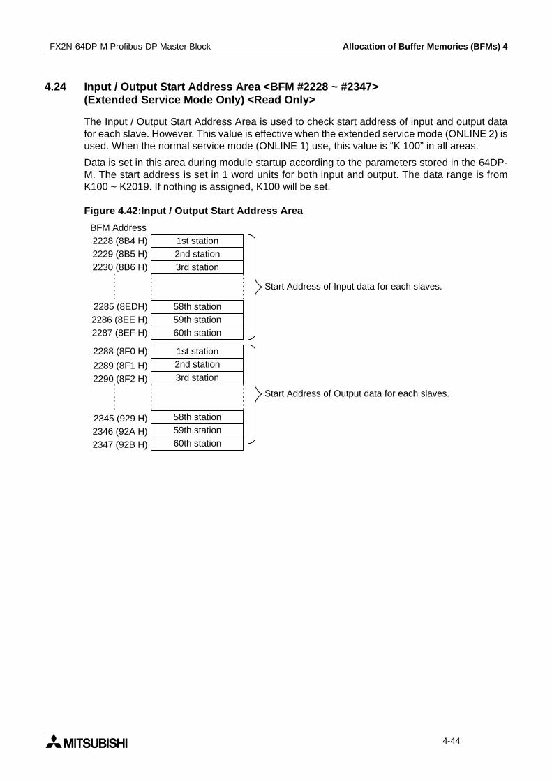
FX2N-64DP-M Profibus-DP Master Block Allocation of Buffer Memories (BFMs) 4
4.24 Input / Output Start Address Area <BFM #2228 ~ #2347>(Extended Service Mode Only) <Read Only>
The Input / Output Start Address Area is used to check start address of input and output datafor each slave. However, This value is effective when the extended service mode (ONLINE 2) isused. When the normal service mode (ONLINE 1) use, this value is “K 100” in all areas.
Data is set in this area during module startup according to the parameters stored in the 64DP-M. The start address is set in 1 word units for both input and output. The data range is fromK100 ~ K2019. If nothing is assigned, K100 will be set.
Figure 4.42:Input / Output Start Address Area
1st stationBFM Address2228 (8B4 H)2229 (8B5 H)2230 (8B6 H)
2289 (8F1 H)2290 (8F2 H)
2345 (929 H)2346 (92A H)
2288 (8F0 H)
2347 (92B H)
2285 (8EDH)2286 (8EE H)2287 (8EF H)
2nd station3rd station
58th station59th station60th station
1st station2nd station3rd station
58th station59th station60th station
Start Address of Input data for each slaves.
Start Address of Output data for each slaves.
4-44
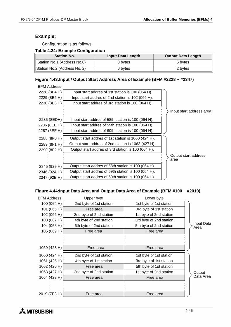
FX2N-64DP-M Profibus-DP Master Block Allocation of Buffer Memories (BFMs) 4
Example;
Configuration is as follows.
Figure 4.43:Input / Output Start Address Area of Example (BFM #2228 ~ #2347)
Figure 4.44:Input Data Area and Output Data Area of Example (BFM #100 ~ #2019)
Table 4.24: Example ConfigurationStation No. Input Data Length Output Data Length
Station No.1 (Address No.0) 3 bytes 5 bytes
Station No.2 (Address No. 2) 6 bytes 2 bytes
Input start addres of 1st station is 100 (064 H).BFM Address2228 (8B4 H)2229 (8B5 H)2230 (8B6 H)
2289 (8F1 H)2290 (8F2 H)
2345 (929 H)2346 (92A H)
2288 (8F0 H)
2347 (92B H)
2285 (8EDH)2286 (8EE H)2287 (8EF H)
Input start addres of 2nd station is 102 (066 H).Input start addres of 3rd station is 100 (064 H).
Input start addres of 58th station is 100 (064 H).Input start addres of 59th station is 100 (064 H).Input start addres of 60th station is 100 (064 H).
Output start addres of 1st station is 1060 (424 H).Output start addres of 2nd station is 1063 (427 H).Output start addres of 3rd station is 100 (064 H).
Output start addres of 58th station is 100 (064 H).Output start addres of 59th station is 100 (064 H).Output start addres of 60th station is 100 (064 H).
Input start address area
Output start addressarea
2nd byte of 1st station 1st byte of 1st stationBFM Address
100 (064 H)3rd byte of 1st station101 (065 H)
2nd byte of 2nd station 1st byte of 2nd station102 (066 H)4th byte of 2nd station 3rd byte of 2nd station103 (067 H)
Upper byte Lower byte
6th byte of 2nd station 5th byte of 2nd stationFree area
2nd byte of 1st station 1st byte of 1st station1060 (424 H)4th byte of 1st station 3rd byte of 1st station1061 (425 H)
5th byte of 1st station1062 (426 H)1063 (427 H)
Free area
Free area
Free area Free area
Free area
Free area2nd byte of 2nd station 1st byte of 2nd station
Free area Free area
Free area
1059 (423 H)
1064 (428 H)
2019 (7E3 H)
104 (068 H)105 (069 H)
Input DataArea
OutputData Area
4-45
FX2N-64DP-M Profibus-DP Master Block Allocation of Buffer Memories (BFMs) 4
MEMO
4-46
Global Control 5FX2N-64DP-M Profibus-DP Master Block
5. Global Control
The 64DP-M supports SYNC/UNSYNC and FREEZE/UNFREEZE global control service.The 64DP-M is normally set as UNSYNC and UNFREEZE in global control mode.
5.1 SYNC and UNSYNC Global Control
The SYNC/UNSYNC global control commands the output data communication from themaster to the slave.
1) SYNC global control commandThe output data to the slave which belongs to the group which is specified by BFM #2181 ismade to freeze (not refresh output data). When the following SYNC/UNSYNC global controlcommand is sent, output data to those slaves is updated.
2) UNSYNC global control commandSYNC global control mode of the slave which belongs to the group which specifies by BFM#2181 is released. Output data is updated by usual polling.
Note
When using SYNC global control command, output data (sending to slave) is not refresheduntil next SYNC or UNSYNC global command is send to the slave. That is, even if output(send) data to the slave writes new data in the output data area (BFM #1060 ~ #2019) byTO instructions, these are not refreshed until the following SYNC or UNSYNC globalcommand is issued from the Profibus-DP in SYNC global control mode.
5.2 FREEZE and UNFREEZE Global Control
The FREEZE/UNFREEZE global control commands the input data communication from theslave to the master.
1) FREEZE global control commandThe input data of the slave which belongs to the group which specifies by BFM #2181 ismade to freeze (not refresh input data). When the following FREEZE/UNFREEZE globalcontrol command is sent, input data from those slaves is updated.
2) UNFREEZE global control commandFREEZE global control mode of the slave which belongs to the group which specifies byBFM #2181 is released. Input data is updated by usual polling.
Note
When using FREEZE global control command, input data (receiving from slave) is notrefreshed until next FREEZE or UNFREEZE global command is send to the slave. That is,even if input (receive) data from the slave reads the input data area (BFM #1000 ~ #2019)by FROM instructions, these are not refreshed until the following FREEZE or UNFREEZEglobal command is issued from the Profibus-DP in FREEZE global control mode.
5-1
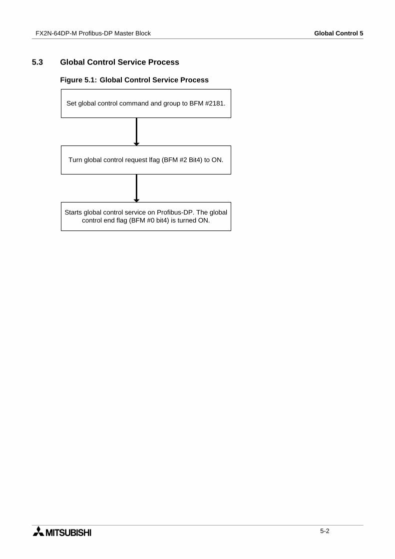
FX2N-64DP-M Profibus-DP Master Block Global Control 5
5.3 Global Control Service Process
Figure 5.1: Global Control Service Process
Set global control command and group to BFM #2181.
Turn global control request lfag (BFM #2 Bit4) to ON.
Starts global control service on Profibus-DP. The globalcontrol end flag (BFM #0 bit4) is turned ON.
5-2

Mode and Displayed Station Address 6FX2N-64DP-M Profibus-DP Master Block
6. Mode and Displayed Station Address
6.1 Mode
The 64DP-M has 4 modes, decided by the mode setting switch. For setting instructions, referto subsection 6.1.1.
6.1.1 Mode Setting Switch
The mode is decided by the mode setting switch. Default setting is “0” (Online 1 mode).
Caution
When changing the Mode, the power supply of the PLC and 64DP-M should be OFF.
Figure 6.1: Mode Switch
Table 6.1: ModeMode Description
ONLINE 1 (Normal service mode) 64DP-M can exchange 32 bytes/slave.
ONLINE 2 (Extended service mode) 64DP-M can exchange 244 byte/slave.
PRE SET (Parameter Setting mode) This mode is used for setting the parameter.
TEST (Self diagnostic mode)This mode is used for checking hardware of 64DP-M. For selftest, refer to subsection 9.3.
Table 6.2: Mode SwitchMode Switch
PositionsMode
0 ONLINE 1 (Normal service mode)
1 PRE SET (Parameter Setting mode)
2 TEST (Self diagnostic mode)
E ONLINE 2 (Extended service mode)
3 ~ D, F Not used
! " #
$ % & " " ! " #
' ( ) ' % % % & * ! " #
) ) + * & , % ! " #
6-1

FX2N-64DP-M Profibus-DP Master Block Mode and Displayed Station Address 6
6.2 Displayed Station Address
The station address set by parameter is displayed by the STATION LEDs when 64DP-M isONLINE 1 and ONLINE 2 mode. The station address is displayed by the STATION LED (B0-B6) in binary. The parameter is set by configuration software (ProfiMap). For the ProfiMapconfiguration software, please see the MELSEC ProfiMap Configuration System for OpenNetworks Software Manual.
Example
When station address is 10, display is as follows.
Figure 6.2: Example Displayed Station Address
TEST
B6
B5
B4
B3
B2
B1
B0
ST NO
64
32
16
8
4
2
1
: LED is not lit.
: LED is lit.
6-2
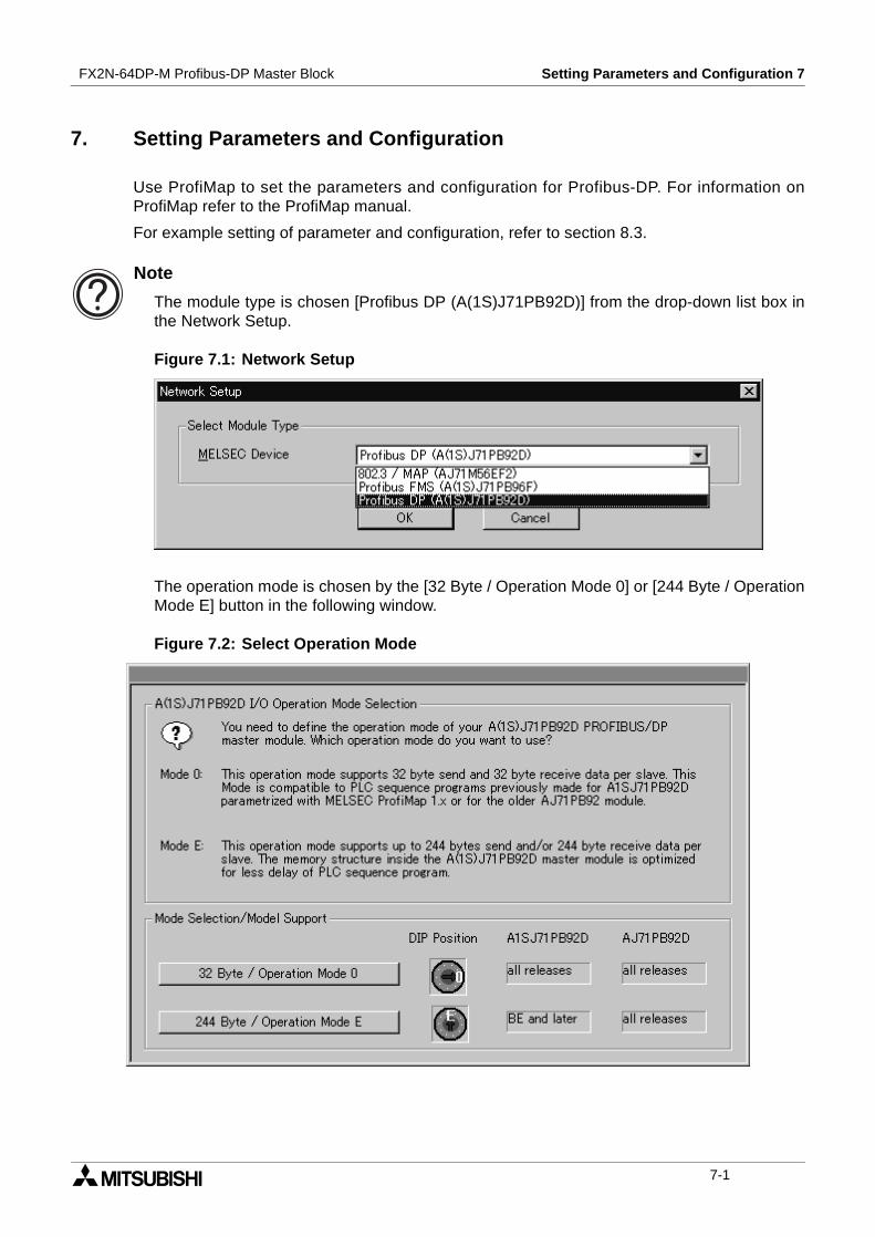
Setting Parameters and Configuration 7FX2N-64DP-M Profibus-DP Master Block
7. Setting Parameters and Configuration
Use ProfiMap to set the parameters and configuration for Profibus-DP. For information onProfiMap refer to the ProfiMap manual.
For example setting of parameter and configuration, refer to section 8.3.
Note
The module type is chosen [Profibus DP (A(1S)J71PB92D)] from the drop-down list box inthe Network Setup.
Figure 7.1: Network Setup
The operation mode is chosen by the [32 Byte / Operation Mode 0] or [244 Byte / OperationMode E] button in the following window.
Figure 7.2: Select Operation Mode
7-1
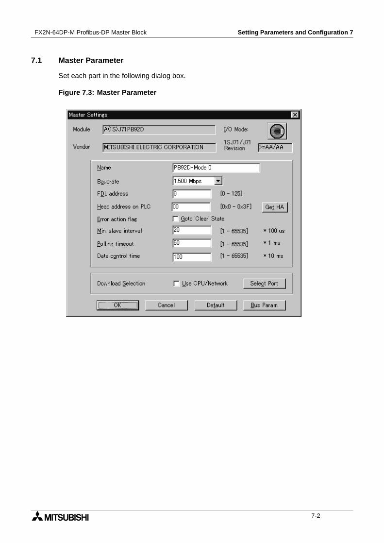
FX2N-64DP-M Profibus-DP Master Block Setting Parameters and Configuration 7
7.1 Master Parameter
Set each part in the following dialog box.
Figure 7.3: Master Parameter
7-2
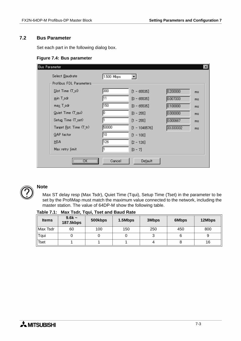
FX2N-64DP-M Profibus-DP Master Block Setting Parameters and Configuration 7
7.2 Bus Parameter
Set each part in the following dialog box.
Figure 7.4: Bus parameter
Note
Max ST delay resp (Max Tsdr), Quiet Time (Tqui), Setup Time (Tset) in the parameter to beset by the ProfiMap must match the maximum value connected to the network, including themaster station. The value of 64DP-M show the following table.
Table 7.1: Max Tsdr, Tqui, Tset and Baud Rate
Items9.6k ~
187.5kbps500kbps 1.5Mbps 3Mbps 6Mbps 12Mbps
Max Tsdr 60 100 150 250 450 800
Tqui 0 0 0 3 6 9
Tset 1 1 1 4 8 16
7-3
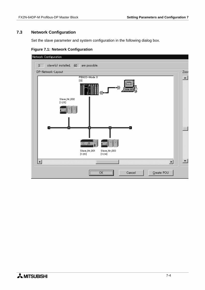
FX2N-64DP-M Profibus-DP Master Block Setting Parameters and Configuration 7
7.3 Network Configuration
Set the slave parameter and system configuration in the following dialog box.
Figure 7.1: Network Configuration
7-4

Example Program 8FX2N-64DP-M Profibus-DP Master Block
8. Example Program
8.1 System Configuration
Figure 8.1: System Configuration
8.2 Contents of Operation
• D0 ~ D15 of master (FX2N PLC) is written in D0 ~ D15 of slave station 1 (FX0N PLC), andD20 ~ D35 of slave station 1 is written to D40 ~ D55 of master. In slave station 1 D0 ismoved to D20 and D1 is moved to D21. Therefore, the value of D0 and D1 that sent frommaster to slave station 1 returns to D40 and D41.
• D60 in master (FX2N PLC) is output to the FX2N-16EYR-ES/UL on the slave station 2 (FX2N-32DP-IF), and the input status of FX2N-16EX-ES/UL on the slave station 2 are read to D20in master.
• When an error occurs on Profibus-DP, the error information is stored in D400 ~ D439, andY000 is turned ON.When X000 is turned ON, 64DP-M recovers from error, and Y000 is turned OFF.When X001 is turned ON, the diagnostic information in D400 ~ D439 are cleared.
• When X002 is turned ON, the 64DP-M will restart.
• When X003 is turned ON with a watchdog timer error in 64DP-M, 64DP-M recovers fromthis error, and the 64DP-M will restart.
FX2N
SeriesFX2N-64DP-M(Address No.0)
FX0N
Series
Profibus-DP Network
Terminating resistor
Terminatingresistor
ConfigurationSoftware (ProfiMap
3.0 or more)
FX0N-32NT-DP
Slave station No.1(Address No.1)
FX2N-32DP-IF
Slave station No.2(Address No.2)
FX2N-16EX-ES/UL
FX2N-16EYR-ES/UL
8-1
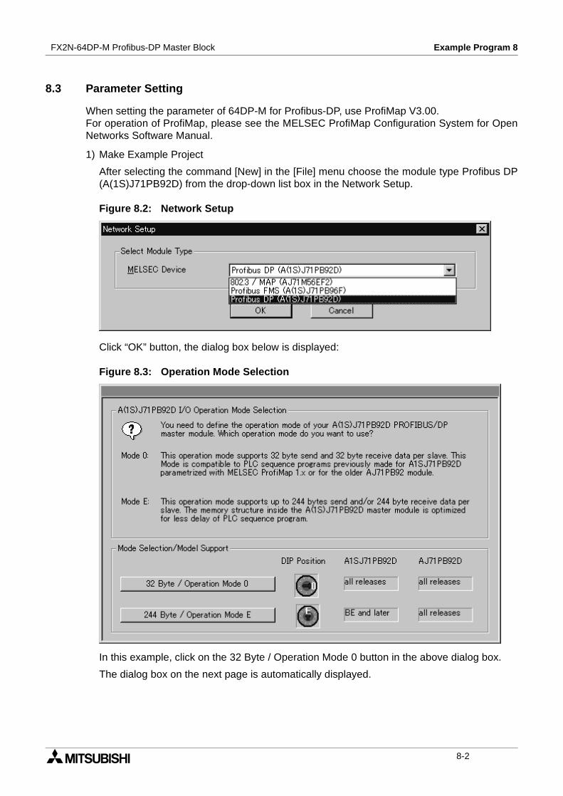
FX2N-64DP-M Profibus-DP Master Block Example Program 8
8.3 Parameter Setting
When setting the parameter of 64DP-M for Profibus-DP, use ProfiMap V3.00.For operation of ProfiMap, please see the MELSEC ProfiMap Configuration System for OpenNetworks Software Manual.
1) Make Example Project
After selecting the command [New] in the [File] menu choose the module type Profibus DP(A(1S)J71PB92D) from the drop-down list box in the Network Setup.
Figure 8.2: Network Setup
Click “OK” button, the dialog box below is displayed:
Figure 8.3: Operation Mode Selection
In this example, click on the 32 Byte / Operation Mode 0 button in the above dialog box.
The dialog box on the next page is automatically displayed.
8-2

FX2N-64DP-M Profibus-DP Master Block Example Program 8
Figure 8.4: Project
- When clicking on the Master Parameter button, the master setting window opens.For master setting, refer to next page “2) Master parameter”.
- When clicking on the Define I/O-Slaves button, the network configuration window opens.For network configuration, refer to “3) Network configuration”.
- When clicking on the Write to AJ71 button, this project data is downloaded to 64DP-M
8-3

FX2N-64DP-M Profibus-DP Master Block Example Program 8
2) Master Setting
Within the Master parameters, the baud rate, different addresses and other parameters forthe 64DP-M can be set.
Figure 8.5: Master Setting
8-4

FX2N-64DP-M Profibus-DP Master Block Example Program 8
3) Network configuration
When clicking on the Define I/O-Slaves button, a symbolic graphical display of the networkcomes up which contains only the master station and the ProfiMap PC with the currentlyselected connection to the master station.
Figure 8.6: Insert New Insert DP-Slave
Right-click within the graphical network configuration editor and select Insert DP-Slave toaccess the Device Database.
8-5

FX2N-64DP-M Profibus-DP Master Block Example Program 8
After having selected a group in the window Device Database, a list of all slave modelsassigned to the respective group is displayed. For the selected slave the vendor andrevision string, the path of the GSD file along with a thumbnail image of the bitmap and thebitmap file are displayed.
a) Setting of FX0N-32NT-DPWhen PLC is selected in “Slave Device Group”, the GSD Device Database dialog boxappears as shown below.
Figure 8.7: Select Slave module
When a FX0N-32NT-DP is selected and the <OK> button has been pressed, the SlaveParameter Settings dialog box appears as shown below.
Figure 8.8: Slave Parameter Settings
8-6
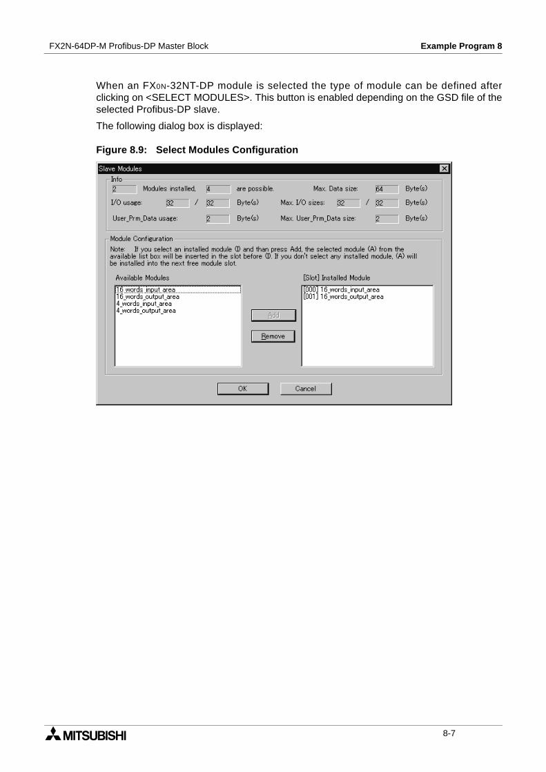
FX2N-64DP-M Profibus-DP Master Block Example Program 8
When an FX0N-32NT-DP module is selected the type of module can be defined afterclicking on <SELECT MODULES>. This button is enabled depending on the GSD file of theselected Profibus-DP slave.
The following dialog box is displayed:
Figure 8.9: Select Modules Configuration
8-7
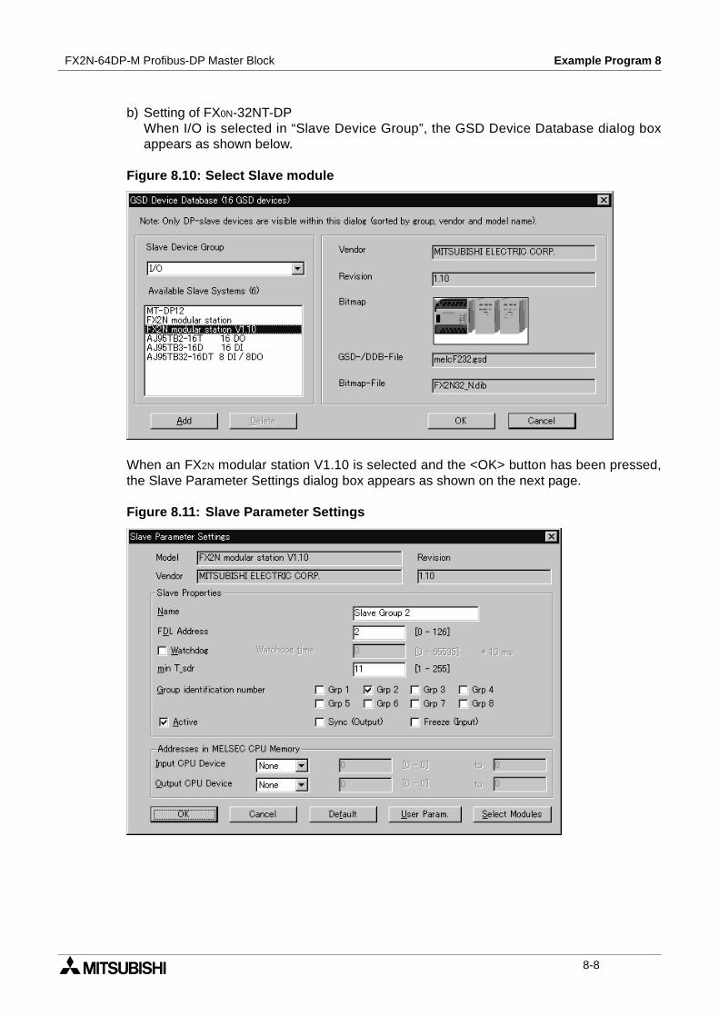
FX2N-64DP-M Profibus-DP Master Block Example Program 8
b) Setting of FX0N-32NT-DPWhen I/O is selected in “Slave Device Group”, the GSD Device Database dialog boxappears as shown below.
Figure 8.10: Select Slave module
When an FX2N modular station V1.10 is selected and the <OK> button has been pressed,the Slave Parameter Settings dialog box appears as shown on the next page.
Figure 8.11: Slave Parameter Settings
8-8
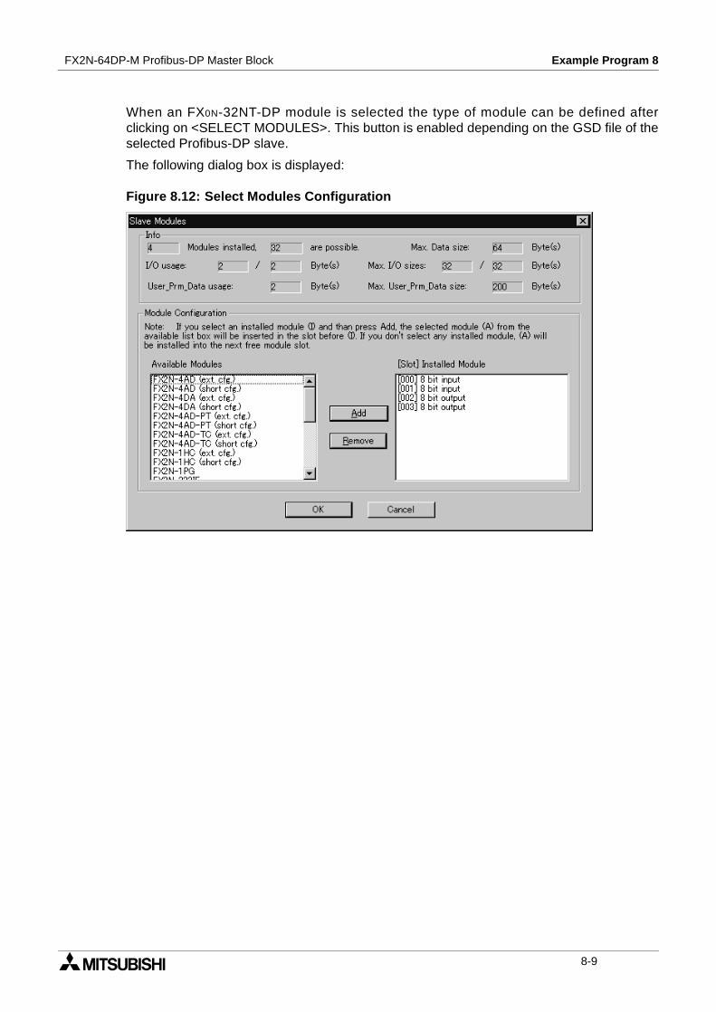
FX2N-64DP-M Profibus-DP Master Block Example Program 8
When an FX0N-32NT-DP module is selected the type of module can be defined afterclicking on <SELECT MODULES>. This button is enabled depending on the GSD file of theselected Profibus-DP slave.
The following dialog box is displayed:
Figure 8.12: Select Modules Configuration
8-9
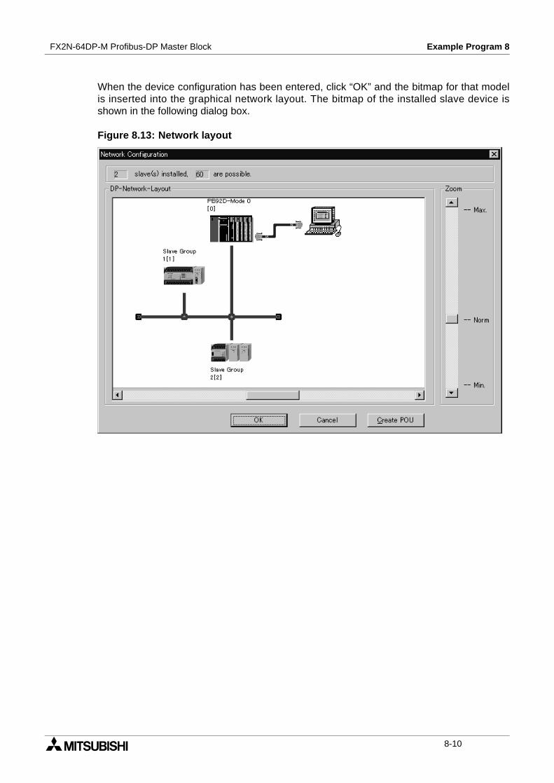
FX2N-64DP-M Profibus-DP Master Block Example Program 8
When the device configuration has been entered, click “OK” and the bitmap for that modelis inserted into the graphical network layout. The bitmap of the installed slave device isshown in the following dialog box.
Figure 8.13: Network layout
8-10
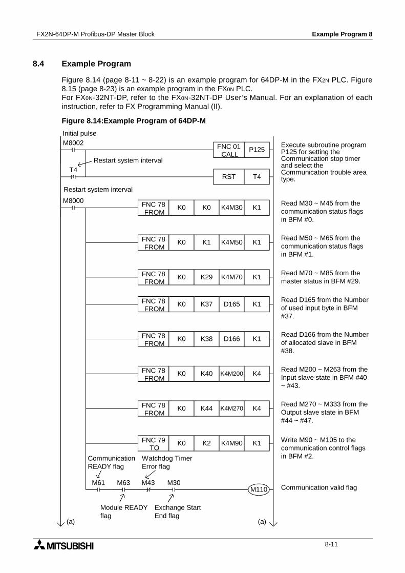
FX2N-64DP-M Profibus-DP Master Block Example Program 8
8.4 Example Program
Figure 8.14 (page 8-11 ~ 8-22) is an example program for 64DP-M in the FX2N PLC. Figure8.15 (page 8-23) is an example program in the FX0N PLC.For FX0N-32NT-DP, refer to the FX0N-32NT-DP User’s Manual. For an explanation of eachinstruction, refer to FX Programming Manual (II).
Figure 8.14:Example Program of 64DP-M
Communication valid flagM61 M63 M43 M30
T4
M8002Initial pulse
Execute subroutine programP125 for setting theCommunication stop timerand select theCommunication trouble areatype.
Read M30 ~ M45 from thecommunication status flagsin BFM #0.
Read M70 ~ M85 from themaster status in BFM #29.
Read D165 from the Numberof used input byte in BFM#37.
Read M50 ~ M65 from thecommunication status flagsin BFM #1.
M8000
Restart system interval
Restart system interval
Write M90 ~ M105 to thecommunication control flagsin BFM #2.
P125FNC 01CALL
RST T4
FNC 78FROM
K0 K0 K4M30 K1
FNC 78FROM
K0 K1 K4M50 K1
FNC 78FROM
K0 K29 K4M70 K1
FNC 78FROM
K0 K38 D166 K1
FNC 78FROM
K0 K40 K4M200 K4
FNC 78FROM
K0 K37 D165 K1
FNC 78FROM
K0 K44 K4M270 K4
FNC 79TO
K0 K2 K4M90 K1
Read D166 from the Numberof allocated slave in BFM#38.
Read M200 ~ M263 from theInput slave state in BFM #40~ #43.
Read M270 ~ M333 from theOutput slave state in BFM#44 ~ #47.
M110
CommunicationREADY flag
Module READYflag
Watchdog TimerError flag
Exchange StartEnd flag
(a)(a)
8-11
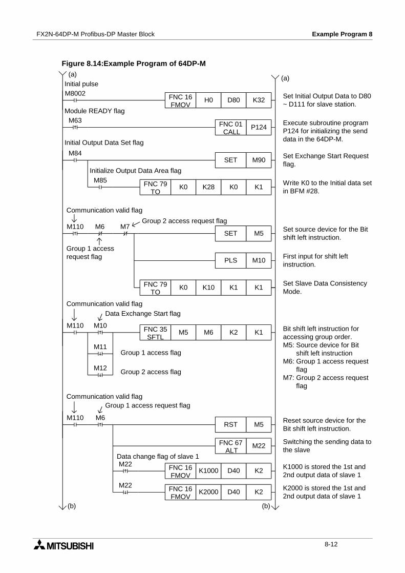
FX2N-64DP-M Profibus-DP Master Block Example Program 8
Figure 8.14:Example Program of 64DP-M
Set Initial Output Data to D80~ D111 for slave station.
Set Exchange Start Requestflag.
Write K0 to the Initial data setin BFM #28.
Execute subroutine programP124 for initializing the senddata in the 64DP-M.
Set source device for the Bitshift left instruction.
Reset source device for theBit shift left instruction.
Communication valid flag
Group 1 access flag
Set Slave Data ConsistencyMode.
M8002
M63
M84
M85
M110 M6 M7
FNC 16FMOV
H0 D80 K32
P124FNC 01CALL
SET M90
FNC 79TO
K0 K28 K0 K1
Initial pulse(a) (a)
Module READY flag
Bit shift left instruction foraccessing group order.M5: Source device for Bit
shift left instructionM6: Group 1 access request
flagM7: Group 2 access request
flag
Initial Output Data Set flag
Initialize Output Data Area flag
Communication valid flag
Group 1 accessrequest flag
Group 2 access request flag
FNC 79TO
K0 K10 K1 K1
SET M5
PLS M10
M110 M10
M11
M12
M6
M22
M22
M110
FNC 35SFTL
M5 M6 K2 K1
RST M5
M22FNC 67ALT
FNC 16FMOV
K1000 D40 K2
FNC 16FMOV
K2000 D40 K2
First input for shift leftinstruction.
Group 2 access flag
Communication valid flag
Switching the sending data tothe slave
K1000 is stored the 1st and2nd output data of slave 1
Data Exchange Start flag
Data change flag of slave 1
K2000 is stored the 1st and2nd output data of slave 1
(b)(b)
Group 1 access request flag
8-12

FX2N-64DP-M Profibus-DP Master Block Example Program 8
Figure 8.14:Example Program of 64DP-M
M23
M23
M7
M110
M110 M130 M6
M20 M34
M110
(b) (b)Communication valid flag
Group 2 access request flag
SET M5
M23FNC 66ALT
HFFFF D60FNC 12MOV
H0000 D60FNC 12MOV
Reset source device for theBit shift left instruction.
Switching the sending data toslave 2
HFFFF is stored the 1st and2nd output data of slave 2
H0000 is stored the 1st and2nd output data of slave 2
Data change flag of slave 2
FNC 78FROM
K0 K2212 K1M120 K1
Communication valid flag
Read M120 ~ M123 from theCommunication Status ForAll in BFM #2212.
Read M130 ~ M193 from theCommunication Status ForEach Station in BFM #2213 ~#2216.
FNC 78FROM
K0 K2213 K4M130 K4
FNC 78FROM
K0 K15 K4M340 K4
FNC 78FROM
K0 K19 K4M410 K4
Read M340 ~ M403 from theoutput data sending end flagfor each station in BFM #15 ~#18.
Read M410 ~ M473 from theoutput data send error flagfor each station in BFM #19 ~#23.Communication valid flag
FNC 79TO
K0 K2181 H0128 K1 Set the global controlcommand in BFM #2181(Global Control Area).Object group: Group 1Global control: FREEZE and
SYNC
SET M20 Set flag of FREEZE andSYNC for group 1.
SET M94
RST M20
Set Global Control Requestflag.
Reset flag of FREEZE andSYNC for group 1.
Group 1 access request flag
slave 1 Errorflag
Global Control End flag
FREEZE and SYNC flag forgroup 1.
(b) (c)
8-13
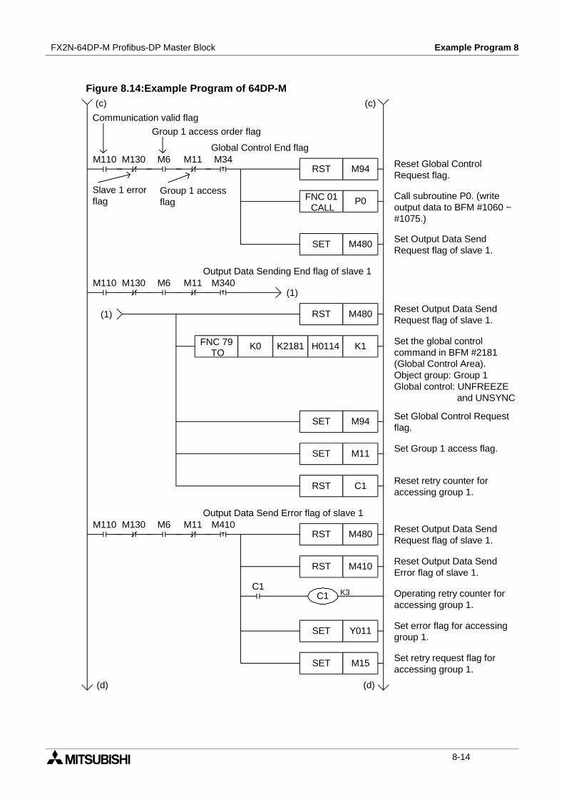
FX2N-64DP-M Profibus-DP Master Block Example Program 8
Figure 8.14:Example Program of 64DP-M
M130M110 M6 M11 M340
M130M110 M6 M11 M410
C1
M130M110 M6 M11 M34RST M94
SET M480
P0FNC 01CALL
FNC 79TO
K0 K2181 H0114 K1
RST M480
RST C1
SET M94
SET M11
RST M410
K3C1
SET Y011
SET M15
(c) (c)
Communication valid flag
Slave 1 errorflag
Group 1 access order flag
Global Control End flag
Reset Global ControlRequest flag.
Call subroutine P0. (writeoutput data to BFM #1060 ~#1075.)
Set Output Data SendRequest flag of slave 1.
Output Data Sending End flag of slave 1
(1)
Reset Output Data SendRequest flag of slave 1.
Set the global controlcommand in BFM #2181(Global Control Area).Object group: Group 1Global control: UNFREEZE
and UNSYNC
Set Global Control Requestflag.
(1)
Set Group 1 access flag.
Group 1 accessflag
Reset retry counter foraccessing group 1.
Output Data Send Error flag of slave 1
RST M480 Reset Output Data SendRequest flag of slave 1.
Reset Output Data SendError flag of slave 1.
Operating retry counter foraccessing group 1.
Set error flag for accessinggroup 1.
Set retry request flag foraccessing group 1.
(d) (d)
8-14
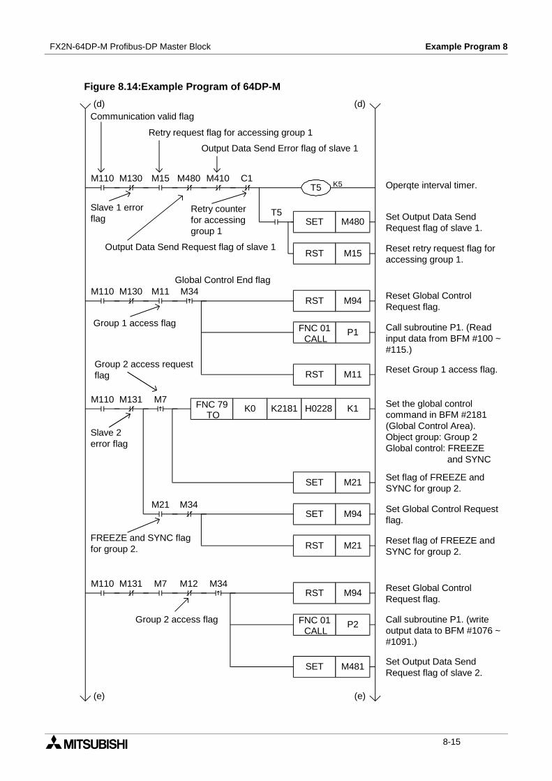
FX2N-64DP-M Profibus-DP Master Block Example Program 8
Figure 8.14:Example Program of 64DP-M
M131M110 M7
M21 M34
M131M110 M12 M34
M130M110 M15 M480 M410 C1
T5
M130M110 M11 M34
K5T5
SET M480
RST M15
RST M94
RST M11
P1FNC 01CALL
Communication valid flag
Slave 1 errorflag
Output Data Send Error flag of slave 1
Retry request flag for accessing group 1
Operqte interval timer.
Set Output Data SendRequest flag of slave 1.
Output Data Send Request flag of slave 1
Retry counterfor accessinggroup 1
(d) (d)
Reset retry request flag foraccessing group 1.
FNC 79TO
K0 K2181 H0228 K1
SET M21
SET M94
RST M21
RST M94
P2FNC 01CALL
SET M481
Global Control End flag
Group 1 access flag
Reset Global ControlRequest flag.
Call subroutine P1. (Readinput data from BFM #100 ~#115.)
Reset Group 1 access flag.
Set the global controlcommand in BFM #2181(Global Control Area).Object group: Group 2Global control: FREEZE
and SYNC
Set flag of FREEZE andSYNC for group 2.
Set Global Control Requestflag.
Reset flag of FREEZE andSYNC for group 2.
Reset Global ControlRequest flag.
Call subroutine P1. (writeoutput data to BFM #1076 ~#1091.)
Set Output Data SendRequest flag of slave 2.
Group 2 access flag
Slave 2error flag
FREEZE and SYNC flagfor group 2.
(e) (e)
Group 2 access requestflag
M7
8-15
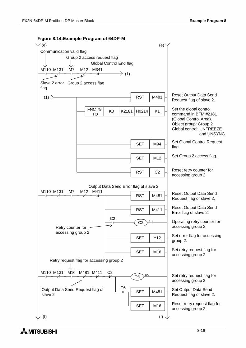
FX2N-64DP-M Profibus-DP Master Block Example Program 8
Figure 8.14:Example Program of 64DP-M
M131M110 M7 M12 M341
M131M110 M7 M12 M411
C2
RST M481
SET M94
(e) (e)
Communication valid flag
Slave 2 errorflag
Group 2 access request flagGlobal Control End flag
(1)
Reset Output Data SendRequest flag of slave 2.
Set the global controlcommand in BFM #2181(Global Control Area).Object group: Group 2Global control: UNFREEZE
and UNSYNC
Set Global Control Requestflag.
(1)
Set Group 2 access flag.
Group 2 access flag
Reset retry counter foraccessing group 2.
Output Data Send Error flag of slave 2
Reset Output Data SendRequest flag of slave 2.
Reset Output Data SendError flag of slave 2.
Operating retry counter foraccessing group 2.
Set error flag for accessinggroup 2.
Set retry request flag foraccessing group 2.
(f) (f)
M131M110 M16 M481 M411 C2
T6
Retry request flag for accessing group 2
Set retry request flag foraccessing group 2.
Set Output Data SendRequest flag of slave 2.
Output Data Send Request flag ofslave 2
Reset retry request flag foraccessing group 2.
FNC 79TO
K0 K2181 H0214 K1
SET M12
RST C2
RST M481
RST M411
K3C2
SET Y12
SET M16
Retry counter foraccessing group 2
K5T6
SET M16
SET M481
8-16

FX2N-64DP-M Profibus-DP Master Block Example Program 8
Figure 8.14:Example Program of 64DP-M
M110
M35
M34M17 M35 C0
M34
FNC 79TO
K0 K11 K4M480 K4
RST M94
SET M94
RST C0
M131M110 M12 M34RST M94
Global Control End flag
Reset Global ControlRequest flag.
Call subroutine P3. (Readinput data from BFM #116 ~#131.)
Reset Group 2 access flag.
P3FNC 01CALL
RST M12
(f) (f)Communication valid flag
Slave 2 error flag
Group 2 access flag
Write the output data sendrequest for each slave toBFM #11 ~ #14.
Reset Global ControlRequest flag.
Set the retry request flag.
Count the number of retries.
SET M17
K3C0
RST M17
Set Global Control Requestflag.
Reset the retry request flag.
Reset the retry counter.
Global Control Error End flag
Retry counter of theGlobal control
Retry request flag
(g) (g)
M31P126FNC 01
CALLPCall subroutine P126. (ReadCommunication Trouble Areaand Expansion Trouble Areafrom BFM #2140~ #2159,#2196 ~ #2210.)
8-17
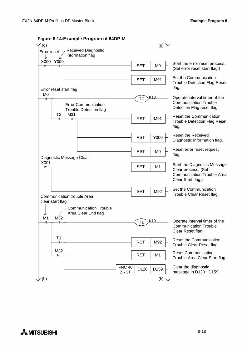
FX2N-64DP-M Profibus-DP Master Block Example Program 8
Figure 8.14:Example Program of 64DP-M
Y000X000
M0
T2 M31
X001
M1
T1
M32
M32
SET M1
K10T1
RST M1
(g) (g)
Error reset Received DiagnosticInformation flag
SET M0 Start the error reset process.(Set error reset start flag.)
Set the CommunicationTrouble Detection Flag Resetflag.
Operate interval timer of theCommunication TroubleDetection Flag reset flag.
Reset the CommunicationTrouble Detection Flag Resetflag.
Reset the ReceivedDiagnostic Information flag.
Reset error reset requestflag.
K10T2
RST M91
RST M0
RST Y000
SET M92
Start the Diagnostic MessageClear process. (SetCommunication Trouble AreaClear Start flag.)
Error reset start flag
Error CommunicationTrouble Detection flag
Diagnostic Message Clear
Set the CommunicationTrouble Clear Reset flag.Communication trouble Area
clear start flag
Communication TroubleArea Clear End flag
Operate interval timer of theCommunication TroubleClear Reset flag.
Reset the CommunicationTrouble Clear Reset flag.
Reset CommunicationTrouble Area Clear Start flag.
Clear the diagnosticmessage in D120 ~D159.
RST M92
D120 D159FNC 40ZRST
(h) (h)
SET M91
8-18
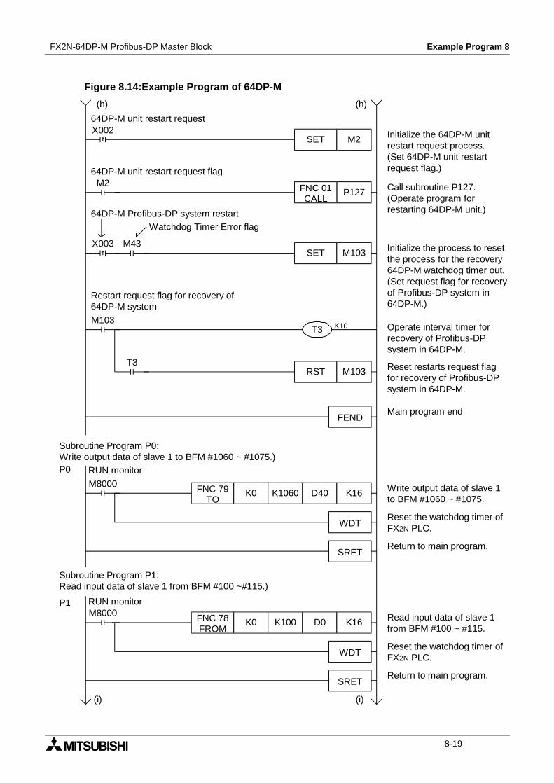
FX2N-64DP-M Profibus-DP Master Block Example Program 8
Figure 8.14:Example Program of 64DP-M
X003 M43
M103
T3
M8000
M8000
FEND
SRET
WDT
SRET
FNC 78FROM
K0 K100 D0 K16
K10T3
RST M103
P0
P1
(h) (h)
Restart request flag for recovery of64DP-M system
Initialize the process to resetthe process for the recovery64DP-M watchdog timer out.(Set request flag for recoveryof Profibus-DP system in64DP-M.)
Watchdog Timer Error flag64DP-M Profibus-DP system restart
X002
M2
SET M2
64DP-M unit restart request
Initialize the 64DP-M unitrestart request process.(Set 64DP-M unit restartrequest flag.)
P127FNC 01CALL
64DP-M unit restart request flag
Call subroutine P127.(Operate program forrestarting 64DP-M unit.)
SET M103
Operate interval timer forrecovery of Profibus-DPsystem in 64DP-M.
Reset restarts request flagfor recovery of Profibus-DPsystem in 64DP-M.
Main program end
Subroutine Program P0:Write output data of slave 1 to BFM #1060 ~ #1075.)
FNC 79TO
K0 K1060 D40 K16
RUN monitor
Subroutine Program P1:Read input data of slave 1 from BFM #100 ~#115.)
WDT
Write output data of slave 1to BFM #1060 ~ #1075.
Reset the watchdog timer ofFX2N PLC.
Return to main program.
Read input data of slave 1from BFM #100 ~ #115.
Reset the watchdog timer ofFX2N PLC.
Return to main program.
RUN monitor
(i) (i)
8-19
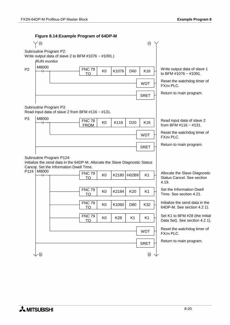
FX2N-64DP-M Profibus-DP Master Block Example Program 8
Figure 8.14:Example Program of 64DP-M
M8000P124 FNC 79TO
K0 K2180 H02B9 K1
FNC 79TO
K0 K2184 K20 K1
WDT
SRET
M8000
M8000
P2
P3
FNC 79TO
K0 K1076 D60 K16
FNC 78FROM
K0 K116 D20 K16
WDT
SRET
WDT
SRET
Subroutine Program P2:Write output data of slave 2 to BFM #1076 ~ #1091.)
RUN monitor
Write output data of slave 1to BFM #1076 ~ #1091.
Reset the watchdog timer ofFX2N PLC.
Return to main program.
Read input data of slave 2from BFM #116 ~ #131.
Reset the watchdog timer ofFX2N PLC.
Return to main program.
(i) (i)
Subroutine Program P3:Read input data of slave 2 from BFM #116 ~ #131.
Subroutine Program P124:Initialize the send data in the 64DP-M. Allocate the Slave Diagnostic StatusCancel. Set the Information Dwell Time.
Allocate the Slave DiagnosticStatus Cancel. See section4.19.
Set the Information DwellTime. See section 4.21.
FNC 79TO
K0 K1060 D80 K32 Initialize the send data in the64DP-M. See section 4.2 1).
Set K1 to BFM #28 (the InitialData Set). See section 4.2 1).
Reset the watchdog timer ofFX2N PLC.
Return to main program.
FNC 79TO
K0 K28 K1 K1
(j)(j)
8-20

FX2N-64DP-M Profibus-DP Master Block Example Program 8
Figure 8.14:Example Program of 64DP-M
M8000P126
(j) (j)
SRET
WDT
SET Y000
FNC 78FROM
K0 K2140 D120 K40
M8000P125 FNC 79TO
K0 K9 K50 K1
Subroutine Program P125:Reset D0 ~ D183 and M0 ~ M543. Set the Communication Stop Timer.
Return to main program.
Set the Communication StopTimer.
Reset D0 ~ D183.
Reset M0 ~ M543.
D0 D183FNC 40ZRST
M0 M543FNC 40ZRST
SRET
Subroutine Program P126:Read the Diagnostic Information from BFM #2140 ~ #2179. Read theExtension Diagnostic Information from BFM # 2196 ~ #2210.
Return to main program.
Reset the watchdog timer ofFX2N PLC.
Reset the watchdog timer ofFX2N PLC.
Read the diagnosticinformation from BFM #2140~ #2179.
Set the received DiagnosticInformation flag.
D120 H200FNC 232AND=
(1)
(1) FNC 23DIV
D122 H100 D160
FNC 78FROM
K0 K2196 D170 K14
Divide D122 into master(D160) and slave (D161)address .
Read the extensiondiagnostic information fromBFM #2196 ~ #2209.
RUN monitor
WDT
D122 = H200
(k) (k)
8-21
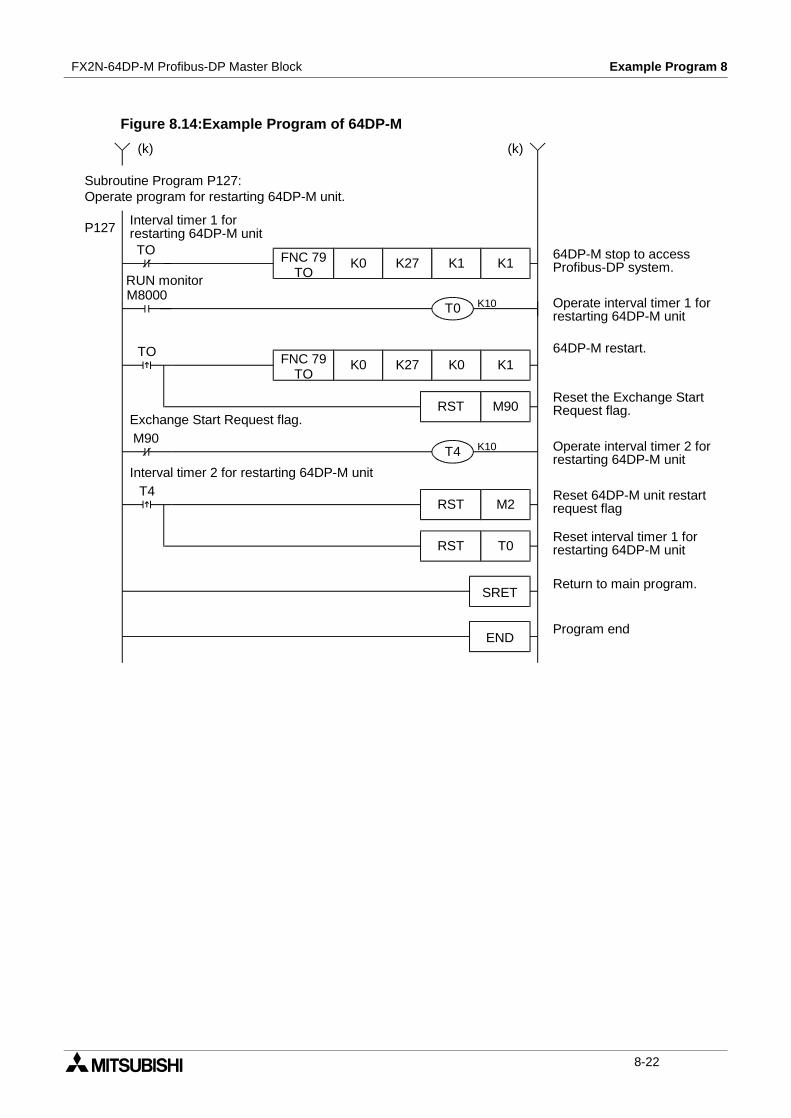
FX2N-64DP-M Profibus-DP Master Block Example Program 8
Figure 8.14:Example Program of 64DP-M
M8000
T4
TO
M90
Reset the Exchange StartRequest flag.
TO
P127
FNC 79TO
K0 K27 K0 K1
K10T4
SRET
END
RST M90
FNC 79TO
K0 K27 K1 K1
K10T0
Subroutine Program P127:Operate program for restarting 64DP-M unit.
Return to main program.
Program end
(k) (k)
Interval timer 1 forrestarting 64DP-M unit
64DP-M stop to accessProfibus-DP system.
Operate interval timer 1 forrestarting 64DP-M unit
RUN monitor
64DP-M restart.
Exchange Start Request flag.
Operate interval timer 2 forrestarting 64DP-M unit
Interval timer 2 for restarting 64DP-M unit
Reset 64DP-M unit restartrequest flag
Reset interval timer 1 forrestarting 64DP-M unit
RST M2
RST T0
8-22
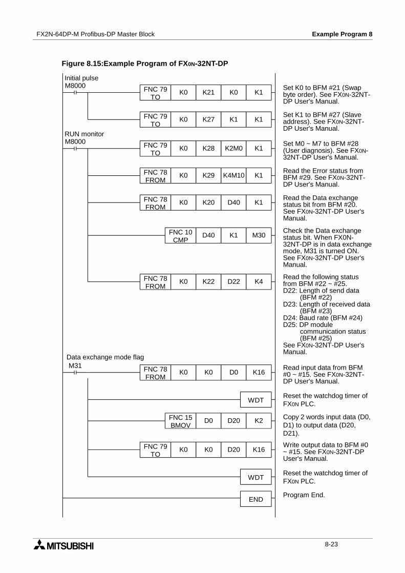
FX2N-64DP-M Profibus-DP Master Block Example Program 8
Figure 8.15:Example Program of FX0N-32NT-DP
M8000
M8000
M31
FNC 78FROM
K0 K22 D22 K4
FNC 15BMOV
D0 D20 K2
WDT
FNC 79TO
K0 K21 K0 K1
FNC 79TO
K0 K27 K1 K1
FNC 79TO
K0 K28 K2M0 K1
FNC 78FROM
K0 K29 K4M10 K1
FNC 78FROM
K0 K20 D40 K1
FNC 78FROM
K0 K0 D0 K16
WDT
END
FNC 10CMP
D40 K1 M30
FNC 79TO
K0 K0 D20 K16
Set K0 to BFM #21 (Swapbyte order). See FX0N-32NT-DP User's Manual.
RUN monitor
Set K1 to BFM #27 (Slaveaddress). See FX0N-32NT-DP User's Manual.
Set M0 ~ M7 to BFM #28(User diagnosis). See FX0N-32NT-DP User's Manual.
Read the Error status fromBFM #29. See FX0N-32NT-DP User's Manual.
Read the Data exchangestatus bit from BFM #20.See FX0N-32NT-DP User'sManual.
Check the Data exchangestatus bit. When FX0N-32NT-DP is in data exchangemode, M31 is turned ON.See FX0N-32NT-DP User'sManual.
Read the following statusfrom BFM #22 ~ #25.D22: Length of send data
(BFM #22)D23: Length of received data
(BFM #23)D24: Baud rate (BFM #24)D25: DP module
communication status(BFM #25)
See FX0N-32NT-DP User'sManual.
Initial pulse
Read input data from BFM#0 ~ #15. See FX0N-32NT-DP User's Manual.
Reset the watchdog timer ofFX0N PLC.
Write output data to BFM #0~ #15. See FX0N-32NT-DPUser's Manual.
Copy 2 words input data (D0,D1) to output data (D20,D21).
Reset the watchdog timer ofFX0N PLC.
Program End.
Data exchange mode flag
8-23
FX2N-64DP-M Profibus-DP Master Block Example Program 8
MEMO
8-24
Diagnostics 9FX2N-64DP-M Profibus-DP Master Block
9. Diagnostics
If the 64DP-M does not see to operate normally, check the following items.
9.1 Preliminary Checks
1) Check “POWER LED”
If “POWER LED” is OFF, check the wiring of the 24V DC power supply, and check whetherthe 24V DC voltage source capacity is sufficient.
2) Check “RUN LED”
If “RUN LED” is OFF, check status of the Exchange Start Request (BFM #2 Bit0). If this bit isOFF, turns this bit to ON.
3) Check “FAULT LED”
If “FAULT LED” is OFF, check the diagnostic information in the Communication TroubleArea (BFM #2140 ~ #2179). For diagnostic information, refer to section 4.12.
4) Check the wiring and connection for the Profibus-DP
If the wiring and connection for the Profibus-DP is incorrect, correct wiring and connection.
5) Check the system configuration and parameter of the 64DP-M for the Profibus-DP
If the system configuration of Profibus-DP is not corresponding to parameter of the64DP-M, match them.
6) Check the error of the PLC.
If the FROM/TO instruction error occurs at this instruction for the 64DP-M in the PLC,operate correctly this instruction.
9-1
FX2N-64DP-M Profibus-DP Master Block Diagnostics 9
9.2 Check the Status of the LEDs for the 64DP-M
1) POWER LED check
2) RUN LED check
3) SD/RD LED check
4) TOKEN LED check
5) RADY LED check
6) FROM/TO LED check
Table 9.1: POWER LED CheckState Description
Lit The 24V DC power supply (PLC or external power supply) is correctly supplied.
UnlitCheck wiring of power supply, and check whether the 24V DC voltage source capacityof 24V DC power supply.
Table 9.2: RUN LED CheckState Description
Lit Normal Operation
Unlit The watchdog timer timed out. Please contact a service representative.
Table 9.3: SD/RD LED CheckState Description
LitIf 64DP-M is the exchange start processing or exchange stop processing status, thisstate of LED is normal operation. However, when 64DP-M exchange to slave(s), checkparameter setting of slave in 64DP-M.
Flashing 64DP-M exchanges data to the slave(s).
Unlit64DP-M does not exchanges data to the slave(s). Check correctly state of theExchange start end flag (BFM #0 bit 0).
Table 9.4: Token LED CheckState Description
Lit 64DP-M is in operation mode 0 or E.
Flashing 64DP-M is in operation mode 0 or E with a multi master configuration.
Unlit64DP-M is in not operation mode 0 or E. Check mode switch, wiring, address settingabout duplicate address, and if the HSA exceeds the network maximum stationNumber.
Table 9.5: RADY LED CheckState Description
Lit64DP-M is in operation mode 0 or E. If it is not in these mode, please contact a servicerepresentative.
Unlit64DP-M is not operation mode 0 or E. If it is in these mode, please contact a servicerepresentative.
Table 9.6: FROM/TO CheckState Description
Lit BFM in 64DP-M is accessed from PLC.
UnlitBFM in 64DP-M is not accessed from PLC. Please check program about FROM/TOinstruction.
9-2
FX2N-64DP-M Profibus-DP Master Block Diagnostics 9
7) PRM. SET LED check
8) RSP ERR LED check
9) FAULT LED check
Table 9.7: PRM. SET LED CheckState Description
Lit 64DP-M is in operation mode 1.
FlashingWhen this LED is flashing in operation mode 1, there is not parameter in 64DP-M.Please write parameter to 64DP-M.
Unlit 64DP-M is in operation mode 0 or E.
Table 9.8: RSP ERR CheckState Description
Lit64DP-M is fault when exchange data to slave. Check diagnostic information. Fordiagnostic information, refer to section 4.12.
Unlit 64DP-M is normal operation.
Table 9.9: FAULT LED CheckState Description
Lit
1) When exchange start request flag (BFM #2 bit 0) is turned OFF to ON, checkparameter about following points.• There is no active slave on the network.• There is slave station of same as master station address.
2) In other case, please contact a service representative.
Unlit 64DP-M is normal operation.
9-3

FX2N-64DP-M Profibus-DP Master Block Diagnostics 9
9.3 Self Diagnostic of the 64DP-M
When setting the self diagnostic mode (The mode switch is “2” position.), TEST LED and STNO LED will be lit as following table. When the test result is normal, these tests are repeated inorder of a) - e). If an error is detected, then the LED status at the tie the error occurs for thattest will be displayed. If error state is displayed, please contact a service representative.
: This LED is not lit. : This LED is lit.
Figure 9.1: LED Location
9.4 Diagnostic Information and Error Code
For error code and diagnostic information, refer to section 4.18. For expansion diagnosticinformation, refer to section 4.19.
Table 9.10: Self DiagnosticItems LED State
Description Order TEST B6 B5 B4 B3 B2 B1 B0
MPU testDuring test a)
Error -
Timer testDuring test b)
Error -
Interrupt testDuring test c)
Error -
DRAM testDuring test
d)
e)
Error -
TEST
B6
B5
B4
B3
B2
B1
B0
ST NO
: LED is not lit.
: LED is lit.
9-4

Appendix AFX2N-64DP-M Profibus-DP Master Block
Appendix A:Further Information Manual List
Table A-1: Further Information Manual ListManual name Manual No. Discription
FX2N SeriesProgrammable controllersHardware Manual
JY992D66301This manual contents expianations for wiring,installation and specification, etc. about FX2N Seriesprogrammable controller.
FX Series ofProgrammable controllersProgramming Manual ΙΙ
JY992D88101This manual contains explanations for instruction ofthe FX1S, FX1N, FX2N and FX2NC Seriesprogrammable controller.
FX0N-32NT-DPProfibus-DP Interface UnitUser’s Manual
JY992D61401This manual contents expranations for wiring,installation, specification and allocation BFM’s, etc.about FX0N-32NT-DP Profibus-DP Interface Unit.
FX2N-32DP-IFProfibus-DP Interface UnitHardware Manual
JY992D77101
This manual contents explanations for wiring,installation and specification, etc. about FX2N-32DP-IFProfibus-DP Interface Unit.However, this hardware manual’s text is alreadycontained in this user’s manual.
FX2N-32DP-IFProfibus-DP Interface UnitUser’s Manual
JY992D79401
This manual contents expranations for wiring,installation, specification and parameter, etc. aboutFX2N-32DP-IF Profibus-DP Interface Unit.However, this hardware manual’s text is alreadycontained in this user’s manual.
FX2N-64DP-MProfibus-DP Master BlockHardware Manual
JY992D82901
This manual contents expranations for wiring,installation and specification, etc. about FX2N-64DP-MProfibus-DP Master Block.However, this hardware manual’s text is alreadycontained in this user’s manual.
MELSEC ProfiMapConfiguration System forOpen Networks SoftwareManual
-This manual contents expranations for operation ofMELSEC ProfiMap Configuration System for OpenNetworks Software.
A-1
FX2N-64DP-M Profibus-DP Master Block Appendix A
MEMO
A-2

HEAD OFFICE: MITSUBISHI DENKI BLDG MARUNOUCHI TOKYO 100-8310 TELEX: J24532 CABLE MELCO TOKYOHIMEJI WORKS: 840, CHIYODA CHO, HIMEJI, JAPAN
JY992D88001B(MEE)
Effective MAR. 2001Specification are subjectto change without notice.
USER’S MANUAL
FX2N-64DP-M Profibus-DP Master Block


