17
One Mustang Drive Cohoes NY 12047 tel +1 518 371 2684 fx +1 518 371 2688 www.pva.net June 2012 FX800 FUME FILTRATION SYSTEM WHERE PRECISION DRIVES PRODUCTION User Guide

One Mustang Drive
Cohoes NY 12047 tel +1 518 371 2684
fx +1 518 371 2688 www.pva.net
June 2012
FX800 FUME FILTRATION
SYSTEM
WHERE PRECISION DRIVES
PRODUCTION
User Guide

Operation and Maintenance Manual Warnings, Cautions, and Notes Certain warning symbols may be affixed to the machine and correspond to notations in this manual. Before operating the FX800, identify warning labels and read the notices described below. While not all labels are on the FX800, it is important to follow these warnings for safe operation.
Always wear approved safety glasses when changing filters.
6040
In situations where inattention could cause either personal injury or damage to equipment a warning notice is used. 6014
Do not smoke near the equipment. Always have a fire extinguisher available for emergency use.
6019
Before operating the system, read and understand the manuals provided with the unit. 6017
Before performing any repairs or maintenance to the system, turn off power. 6011
Never place hands or tools in areas designated by this symbol when the machine is in operation. A dangerous condition may exist. 6008
Warning notices are used to emphasize that hazardous voltages, current, temperatures, or other conditions that could cause personal injury exist in this equipment or may be associated with its use. Only qualified personnel should enter areas designated with this symbol.
6010
Before performing any repairs or maintenance to the system, read and understand the manuals provided with the unit. Only a qualified individual should perform service. 6018

Preface Notice & Disclaimer
CAUTION! If the equipment is used in a manner not specified by PVA, the protection provided by the equipment may be impaired.
Contact Main Office
PVA One Mustang Drive Cohoes, NY 12047 Tel +1-518-371-2684 Fax +1-518-371-2688 Website http://www.pva.net/ Email mailto:[email protected]
Technical Support Tel +1-518-371-2684
Email mailto:[email protected]
Manual Contents Introduction: Provides an overview of the FX800 functionality and physical characteristics.
Installation and Set-up: Describes the procedures for installing the FX800and preparing the system for use. Basic safety practices are reviewed. The safety devices and guarding for the FX800are described. Troubleshooting: Provides a guide to troubleshooting the FX800. A fault diagnosis table is used to lead the operator through common problems and solutions. Several troubleshooting procedures are described.

Maintenance: Provides a preventive maintenance schedule and replacement procedures.
This document is based on information available at the time of its publication. While efforts have been made to be accurate, the information contained herein does not purport to cover all details or variations in hardware or software, or to provide for every possible contingency in connection with installation, operation, or maintenance. Features may be described herein, which are not present in all hardware and software systems. Precision Valve & Automation, Inc. (PVA) assumes no obligation of notice to holders of this document with respect to changes subsequently made.
Precision Valve & Automation, Inc. makes no representation or warranty, expressed, implied, or statutory with respect to, and assumes no responsibility for the accuracy, completeness, sufficiency, or usefulness of the information contained herein. No warranties of merchantability or fitness for purpose shall apply.
This document, including the information contained herein, is the property of Precision Valve & Automation, Inc. and is considered confidential and proprietary information. It is delivered on the express condition that it not be used, disclosed, or reproduced in whole or in part, for any reason without prior written consent of Precision Valve & Automation, Inc. Copyright © 2012 Precision Valve & Automation, Inc. All Rights Reserved

Operation and Maintenance Manual Rev B 12/2011 - iv -
Table of Contents Preface ........................................................................................................................................... ii
Notice & Disclaimer ................................................................................................................................. ii Contact ...................................................................................................................................................... ii
Main Office ....................................................................................................................................... ii Technical Support ............................................................................................................................. ii
Manual Contents ....................................................................................................................................... ii
Table of Contents ......................................................................................................................... iv
Table of Figures ............................................................................................................................. 5
Introduction ................................................................................................................................... 6 Safety Precautions .....................................................................................................................................6
Warnings ............................................................................................................................................6 System Description ....................................................................................................................................7
Installation and Setup ................................................................................................................... 8 Installation .................................................................................................................................................8
Positioning the Machine .....................................................................................................................8 Hose Connection ................................................................................................................................8 Electrical Connection .........................................................................................................................8 Interface Socket (Where Fitted) .........................................................................................................8
Interfacing ..................................................................................................................................................8
Control System .............................................................................................................................. 9 Switching the Machine ON/OFF ........................................................................................................9 Adjusting the Airflow Rate ................................................................................................................9 Determining Airflow Rate ................................................................................................................10 Fully Automatic Operation ...............................................................................................................10
Filtration and Changing Filters .................................................................................................. 11 Changing Filters ......................................................................................................................................11
Changing the Pre-Filter ....................................................................................................................11 Changing the Main Filter .................................................................................................................11
Troubleshooting .......................................................................................................................... 12 Warning and Alarm Statuses ...................................................................................................................12 Troubleshooting Table .............................................................................................................................13
Calling Technical Support ................................................................................................................14 Records .............................................................................................................................................14
Maintenance ................................................................................................................................. 15 Routine Maintenance Schedule ...............................................................................................................15 Part Replacement .....................................................................................................................................16
Ordering Filters and Parts ................................................................................................................16 Return Material Authorization (RMA) ............................................................................................16 Warranty ...........................................................................................................................................16 Shipping ...........................................................................................................................................16 Contacting PVA ...............................................................................................................................16

Operation and Maintenance Manual Rev B 12/2011 - v -
Table of Figures Figure 1: System Description ...........................................................................................................................7 Figure 2: Interfacing .........................................................................................................................................9 Figure 3: Keypad Display .................................................................................................................................9 Figure 4: Graphic Display ..............................................................................................................................10 Figure 5: Machine Diagram ............................................................................................................................12

Operation and Maintenance Manual Rev B 12/2011 - 6 -
Introduction
Safety Precautions
Operation of your fume filtration system involves air pressure, electrical power, mechanical devices, and the handling of hazardous vapors/fumes. It is important that qualified technicians operating and servicing the systems fully understand the systems and safety precautions.
Warnings • Always isolate the system from the main power supply before removing the machine cover.
• Disposable gloves and a dust mask are supplied with replacement filters/prefilters. They should be worn when removing filters and disposed of with the used filter in the provided bag.
• Filters are manufactured from non-toxic materials.
• Filters and prefilters are not re-usable and no attempt should be made to clean them.
• Used filters and prefilters should be disposed of in accordance with local laws and regulations. The company and its agents disclaim all liability and responsibility for any harm, damage, contamination, or injury caused by inappropriate or unlawful disposal.
• PVA systems use high-pressure pumps, which may cause inferior filters to burst and allow hazardous fumes into the workplace. Do not use filters that have only been tested to BS3928, BS5295 or AS208C as these standards are flow checks only and are designed to test filters used in general dust extraction and air conditioning.
• Consult the local regulations concerning fume extraction systems, as these may be subject to requirements including; periodic checks by authorized agencies, re-issue of certificates of compliance or equivalents etc. Consult PVA if in doubt.
Note: Consult PVA for information on maintenance agreements that will ensure conformance to local regulations.
• Locate and define all safety labels around the equipment before powering up.

Operation and Maintenance Manual Rev B 12/2011 - 7 -
System Description
Figure 1: System Description
Legend
1. Access to internal components 2. Control panel 3. Access to replace filters 4. Electrical connections 5. Exhaust air + cooling air 6. Hose 7. Inlet

Operation and Maintenance Manual Rev B 12/2011 - 8 -
Installation and Setup WARNING! The following procedures should be performed by qualified persons in accordance with this manual and all applicable safety regulations. A “qualified person” is defined as “a person or persons who, by possession of a recognized degree, certificate, or professional training, or who, by extensive knowledge, training, and experience, has successfully demonstrated the ability to solve problems relating to the subject matter and work.” (Ref. ANSI/ASME B30.2-1983.)
Installation Positioning the Machine The machine should be as near to the process as possible with space allowed for the following access:
• Internal maintenance
• Control panel, replacing filters
• Exhaust air, cooling air, electrical connections, hose connection
Once in position, lock the two front castors by depressing the foot levers (if present).
Hose Connection Incorrect connection or layout of hose can cause poor airflow, blockages and potentially dangerous build up of fumes. Use the shortest length of hose possible and keep bends to a minimum. Your supplier can advise you of appropriate diameters and layouts of hose for your particular application.
• The best practice is to use the connection kit supplied.
• Do not reduce the diameter of the pipe/hose too much. The use of small diameter pipe/hose or nozzles can reduce the performance of fume extraction systems and so should be avoided.
• If a special connection kit or attachment is required please contact PVA or your local agent.
Ensure all connections are properly sealed and that there are no kinks in the hose. Once secured in position, connect the hose/s to the inlet/s on the machine either by pushing the hose onto the inlet or by using the connections supplied.
Electrical Connection Prior to connecting the power supply, ensure that the voltage, frequency, and power requirements are correct as shown on the label attached to the cabinet rear. Various connection methods are available to order. Ensure power plug is accessible as a disconnect device.
Interface Socket (Where Fitted) When not in use this socket is protected by a screw-on cap.
Interfacing To enable interfacing unscrew the interface socket cap and plug in the interface cable or remote ON/OFF switch (optional). Then connect the other end of the interface cable to your related machine or use the remote ON/OFF switch depending on which you have purchased. Note: There is only one interface socket so an interface cable and the remote ON/OFF switch cannot be used together.

Operation and Maintenance Manual Rev B 12/2011 - 9 -
Figure 2: Interfacing
Control System
Figure 3: Keypad Display
Switching the Machine ON/OFF • To switch the machine ON press the central button on the keypad. The central button will
illuminate (green) and the motor run indicator on the graphic display will rotate.
• Pressing the central button again will switch the machine OFF, extinguish the green light and the motor run indicator on the graphic display will stop rotating.
Adjusting the Airflow Rate • To adjust the airflow rate press the UP and DOWN buttons together. Both buttons will then begin
to flash (red).
• To increase the airflow rate press the UP button, to decrease the airflow rate press the DOWN button.
Interfacing Socket
Remote On/Off Switch Interfacing Cable

Operation and Maintenance Manual Rev B 12/2011 - 10 -
The target airflow measurement is shown on the graphic display together with the actual airflow being achieved by the fume extractor.
Once the target value has been set, do not touch any other buttons. After a few seconds the buttons will cease to flash and the set value will be stored.
Determining Airflow Rate For most applications a good starting point is a flow rate of 50% of the machines maximum capability. Check the fumes are being removed by site observation and appropriate measurement. Then increase or decrease the flow rate as appropriate. Note: Setting the flow level unnecessarily high may reduce filter life.
Fully Automatic Operation The airflow rate is the only parameter that needs to be set by the operator. The FX800 will automatically maintain the airflow level you have set without any further intervention required.
Figure 4: Graphic Display
Filter Status (1,2,3) The FX800 warns the operator if the chemical filter is saturated or the particle filter is blocked. Sensors are also used to warn the operator if particles or gas are passing through the machine into the workplace due to a missing, damaged, or incorrectly fitted filter. When gas or particles are sensed, or the filter is nearly saturated/blocked, the machine will warn the operator with an audible chime and the keypad will flash (red). At this point the filter icon (5) will flash to show which filters may need attention. See Changing Filters Section. Exhaust Temperature (4) When the machine temperature rises above a preset limit the machine will warn the operator with an audible chime every 20 seconds and the keypad will flash (red) every 10 seconds. This feature allows the operator time to identify the problem. If the problem continues then the machine will chime and the keypad will flash (red) every 1-second. See problem solving section. Motor Run Indicator (6) This icon will rotate when the motor is running. Target Airflow / Actual Airflow (7, 8)
Graphic Display: The graphic display shows the operating status of the machine in one easy glance. 1. Column 1 - Filter blocked warning 2. Column 2 - Chemical sensor 3. Column 3 - Particulate sensor 4. Exhaust temperature 5. Filter fault indicators (varies) 6. Motor run indicator 7. Target airflow 8. Actual airflow being achieved
1
2
3
4
5
6
7 8

Operation and Maintenance Manual Rev B 12/2011 - 11 -
The operator can set the target airflow to the level they require, although in most cases this will be factory preset at the correct level. The FX800 will automatically raise or lower the motor speed as required until the actual airflow rate equals the target airflow rate.
Filtration and Changing Filters WARNING! Ensure all filters are fitted correctly prior to using the machine. Do not lift the filters using the handles; these are only to be used for sliding the filters out of the machine. Important Note Always check the extraction nozzle, flexible hose, any pipework, and the air inlet for built-up debris before changing any filter. This avoids false alerts related to airflow. Also, always change the pre-filter first (unless recently changed) and restart the machine. If the alert continues, change the main filter.
Changing Filters The machine will warn you with audible and visible alerts if a filter is exhausted (see control system). The graphic display will flash the icons of the filters, which may need attention. Take care when removing main filters, as they are heavy. Always wear the protective gloves and mask provided, and dispose of them with the used filters in the provided bag. Protective eyewear should also be worn when changing filters. Opening the Cabinet Door: • Ensure your process is stopped • Switch off your FX800 system at the control panel (see Control System) • Turn the door lock/s on the front of the machine • Open the door
Changing the Pre-Filter The FX800 has a pre-filter pad situated in a recess underneath the main filter.
• To remove the pad, first remove the main filter and turn it over (See Changing the Main Filter).
• Remove the pad and replace it with a new one.
• Make sure the harder, smoother side of the pad is facing the main filter.
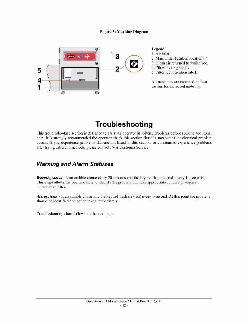
Changing the Main Filter Note: Reference numbers refer to Figure 5: Machine Diagram.
• Open the door
• Turn the filter locking handle (4) 180º counter-clockwise so that it is horizontal and in the "Filter Unlocked" position
• The filter (2) should drop slightly to allow release
• Remove the filter by sliding it towards you and remove it completely from the machine
• Insert the new filter (completely) into the machine ensuring that the airflow arrow on the label (7) is pointing up
• Turn the filter locking handle 180º clockwise so that it is horizontal and in the "Filter Locked" position
• Close and lock the door and restart the machine
Operation and Maintenance Manual Rev B 12/2011 - 12 -
Figure 5: Machine Diagram
Troubleshooting This troubleshooting section is designed to assist an operator in solving problems before seeking additional help. It is strongly recommended the operator check this section first if a mechanical or electrical problem occurs. If you experience problems that are not listed in this section, or continue to experience problems after trying different methods, please contact PVA Customer Service.
Warning and Alarm Statuses Warning status - is an audible chime every 20 seconds and the keypad flashing (red) every 10 seconds. This stage allows the operator time to identify the problem and take appropriate action e.g. acquire a replacement filter. Alarm status - is an audible chime and the keypad flashing (red) every 1-second. At this point the problem should be identified and action taken immediately.
Troubleshooting chart follows on the next page.
Legend 1. Air inlet. 2. Main Filter (Carbon location). † 3. Clean air returned to workplace. 4. Filter locking handle. 5. Filter identification label. All machines are mounted on four castors for increased mobility.
Operation and Maintenance Manual Rev B 12/2011 - 13 -
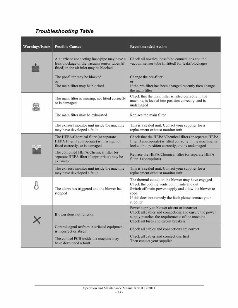
Troubleshooting Table
Warnings/Issues Possible Causes
Recommended Action
A nozzle or connecting hose/pipe may have a leak/blockage or the vacuum sensor tubes (if fitted) in the air inlet may be blocked
Check all nozzles, hose/pipe connections and the vacuum sensor tube (if fitted) for leaks/blockages
The pre-filter may be blocked or The main filter may be blocked
Change the pre-filter or If the pre-filter has been changed recently then change the main filter
The main filter is missing, not fitted correctly or is damaged
Check that the main filter is fitted correctly in the machine, is locked into position correctly, and is undamaged
The main filter may be exhausted Replace the main filter
The exhaust monitor unit inside the machine may have developed a fault
This is a sealed unit. Contact your supplier for a replacement exhaust monitor unit
The HEPA/Chemical filter (or separate HEPA filter if appropriate) is missing, not fitted correctly, or is damaged
Check that the HEPA/Chemical filter (or separate HEPA filter if appropriate) is fitted correctly in the machine, is locked into position correctly, and is undamaged
The combined HEPA/Chemical filter (or separate HEPA filter if appropriate) may be exhausted
Replace the HEPA/Chemical filter (or separate HEPA filter if appropriate)
The exhaust monitor unit inside the machine may have developed a fault
This is a sealed unit. Contact your supplier for a replacement exhaust monitor unit
The alarm has triggered and the blower has stopped
The thermal cutout on the blower may have engaged Check the cooling vents both inside and out Switch off main power supply and allow the blower to cool If this does not remedy the fault please contact your supplier
Blower does not function
Power supply to blower absent or incorrect Check all cables and connections and ensure the power supply matches the requirements of the machine Check all fuses and circuit breakers
Control signal to/from interfaced equipment is incorrect or absent Check all cables and connections are correct
The control PCB inside the machine may have developed a fault
Check all cables and connections first Then contact your supplier

Operation and Maintenance Manual Rev B 12/2011 - 14 -
Warnings/Issues Possible Causes Recommended Action
Odor or particles in exhaust air but there is no alert from the machine
The exhaust monitor unit inside the machine may have developed a fault
Check all cables and connections first Then contact your supplier
Airflow insufficient to remove fume when the filter is not blocked
Airflow set too low or possible airflow leak or a blockage
Increase airflow If problem persists then check all nozzles, hose/pipe connections and the vacuum sensor tube (if fitted) for leaks/blockages
Control signal to/from interfaced equipment is incorrect Equipment is not switched on alarm condition
Electrical problem Check all cables and connections and interfaced equipment
The exhaust monitor unit inside the machine may have developed a fault
Check all cables and connections first, Then contact your supplier
The control PCB inside the machine may have developed a fault
Check all cables and connections first, Then contact your supplier
Buttons and/or graphic display is not illuminated
Power supply absent or incorrect Check all cables and connections and ensure the power supply matches the requirements of the machine
Control signal to/from interfaced equipment is incorrect or absent Check all cables and connections are correct
The control PCB inside the machine may have developed a fault
Check all cables and connections first, Then contact your supplier
A filter has a shorter than expected life
A problem with the pre-filter can cause main filter life to be reduced Check the pre-filter which may be damaged or missing
The process may have changed or increased in duration Check to see if different materials are being used
Check if any factors have changed If the problem persists then contact your supplier
Calling Technical Support The technical support staff is always available to help solve any problems. The phone number is +1-518-371-2684. To assist in the troubleshooting process, it is best if as many of the following items are addressed before calling for help:
Record all the information from when the error occurred. Take note of the operation in progress when the machine developed trouble (when did it have problems, what was it doing, etc.).
Records Any service or replaced filters should be recorded in maintenance records with any other pertinent data for future reference.

Operation and Maintenance Manual Rev B 12/2011 - 15 -
Maintenance Performing the recommended maintenance procedures at the suggested intervals will increase the life of the FX800 and ensure high quality fume/vapor extraction.
Note: Only qualified personnel should perform maintenance.
Routine Maintenance Schedule TIP: Keeping spare filters on hand can help reduce down time. Primary maintenance is filter replacement; the machine control system will indicate when this is required. Filters should be replaced annually if not more often as dictated by the machine. To ensure the smooth running of the extraction machine and associated equipment, please perform the following periodic checks: Daily Visually check that the fumes are
being drawn into the extraction point
Check the status of the display screen
Annually Change filters Consult PVA for maintenance checks.
Replacement filter part numbers are shown on the original packaging. Please ensure that you make a note here for future ordering.
Pre-filter Part Number
Main Filter Part Number
Note: Circuit breaker tripped or fuse blown may indicate a serious fault. Consult your supplier.

Operation and Maintenance Manual Rev B 12/2011 - 16 -
Part Replacement Ordering Filters and Parts Filters and parts can be ordered by contacting Customer Service Support. When ordering spare parts, please be prepare to provide the following information:
Your company name Billing address Shipping address Serial number of the fume extraction system (found on the back of the equipment) Part number or description of item to order Quantity Purchase order or credit card information Shipping instructions
TIP: Keeping spare filters on hand can help reduce down time.
Return Material Authorization (RMA) Obtain a Return Material Authorization (RMA) from Precision Valve & Automation by calling PVA Tech Support.
Warranty The use of filters other than those supplied by PVA will invalidate any warranty, service contract. Contact Precision Valve & Automation for any warranty issue related with spare parts. Shipping When you order parts, please specify which carrier you prefer to use. PVA will determine the best shipping if no instructions are received.
Contacting PVA PVA One Mustang Drive Cohoes, NY 12047 Tel +1-518-371-2684 Fax +1-518-371-2688 Website http://www.pva.net/ Email mailto:[email protected]


