34
FYS3240 PC-based instrumentation and microcontrollers Microcontroller basics Spring 2014 – Lecture #4 Bekkeng, 20.1.2014
FYS3240
PC-based instrumentation and microcontrollers
Microcontroller basics
Spring 2014 – Lecture #4
Bekkeng, 20.1.2014
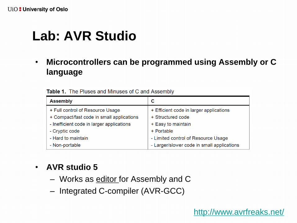
Lab: AVR Studio
• Microcontrollers can be programmed using Assembly or C
language
• AVR studio 5
– Works as editor for Assembly and C
– Integrated C-compiler (AVR-GCC)
http://www.avrfreaks.net/

Microcontroller (µC or uC)
• Microcontrollers have:
– CPU
– Memory
– I/O
• Microcontroller characteristics:
– Used for control and measurements (not a general-purpose computer)
– Does one task and runs one program continuously
– Low power (e.g. 50 mW vs. 50 W or more for a PC)
– Don’t have keyboard and monitor jacks (example of an embedded
system)
– Must use ports to perform I/O
• Selecting a microcontroller
– Should be appropriately scaled for the job

Microprocessors vs. Microcontrollers
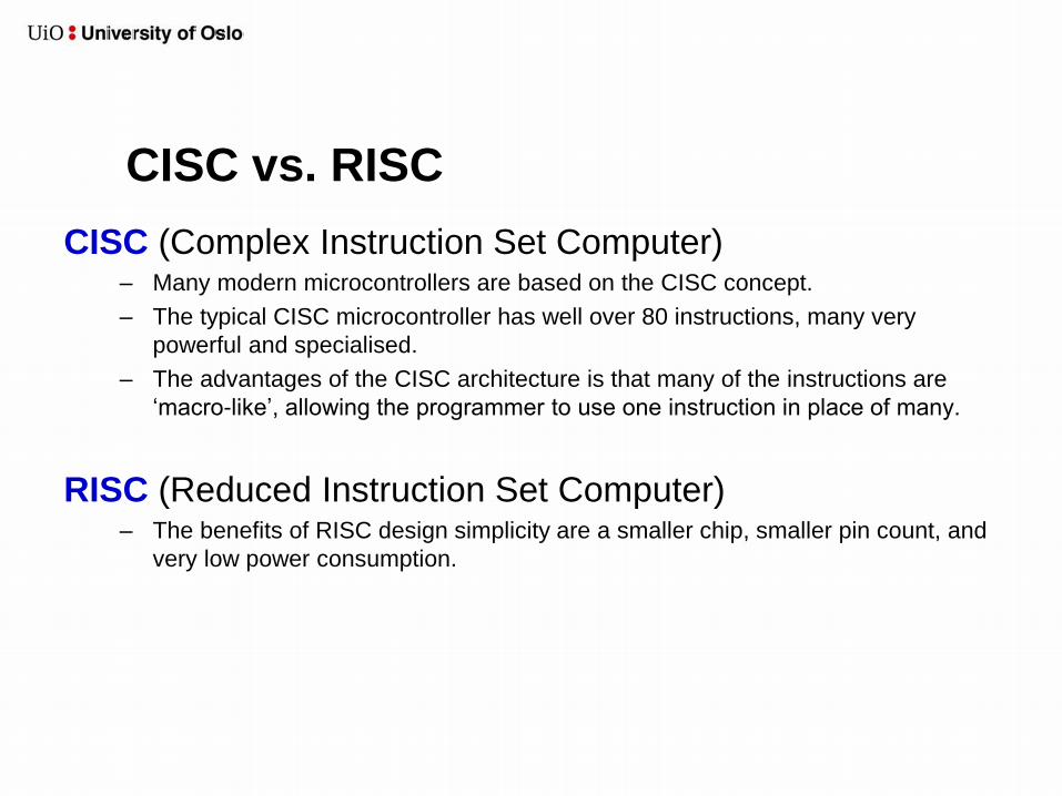
CISC vs. RISC
CISC (Complex Instruction Set Computer) – Many modern microcontrollers are based on the CISC concept.
– The typical CISC microcontroller has well over 80 instructions, many very
powerful and specialised.
– The advantages of the CISC architecture is that many of the instructions are
‘macro-like’, allowing the programmer to use one instruction in place of many.
RISC (Reduced Instruction Set Computer) – The benefits of RISC design simplicity are a smaller chip, smaller pin count, and
very low power consumption.
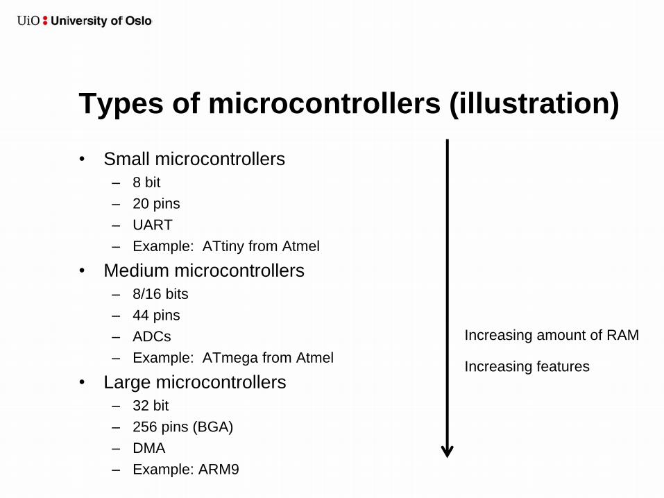
Types of microcontrollers (illustration)
• Small microcontrollers
– 8 bit
– 20 pins
– UART
– Example: ATtiny from Atmel
• Medium microcontrollers
– 8/16 bits
– 44 pins
– ADCs
– Example: ATmega from Atmel
• Large microcontrollers
– 32 bit
– 256 pins (BGA)
– DMA
– Example: ARM9
Increasing amount of RAM
Increasing features
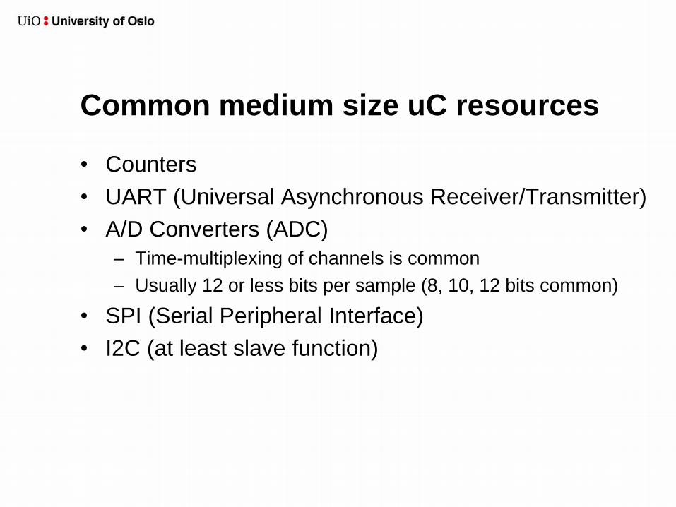
Common medium size uC resources
• Counters
• UART (Universal Asynchronous Receiver/Transmitter)
• A/D Converters (ADC)
– Time-multiplexing of channels is common
– Usually 12 or less bits per sample (8, 10, 12 bits common)
• SPI (Serial Peripheral Interface)
• I2C (at least slave function)
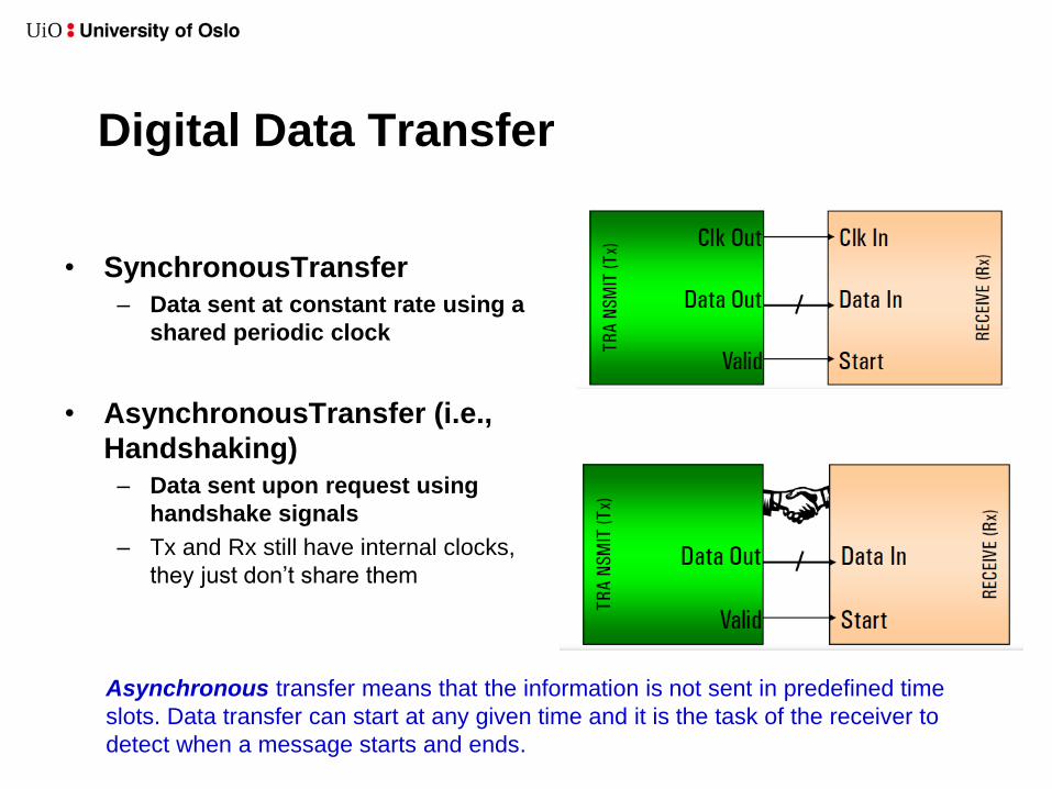
Digital Data Transfer
• SynchronousTransfer
– Data sent at constant rate using a
shared periodic clock
• AsynchronousTransfer (i.e.,
Handshaking)
– Data sent upon request using
handshake signals
– Tx and Rx still have internal clocks,
they just don’t share them
Asynchronous transfer means that the information is not sent in predefined time
slots. Data transfer can start at any given time and it is the task of the receiver to
detect when a message starts and ends.
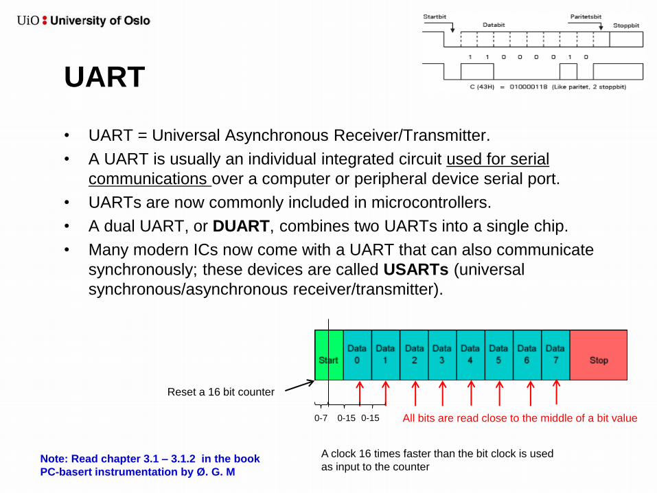
UART
• UART = Universal Asynchronous Receiver/Transmitter.
• A UART is usually an individual integrated circuit used for serial
communications over a computer or peripheral device serial port.
• UARTs are now commonly included in microcontrollers.
• A dual UART, or DUART, combines two UARTs into a single chip.
• Many modern ICs now come with a UART that can also communicate
synchronously; these devices are called USARTs (universal
synchronous/asynchronous receiver/transmitter).
Note: Read chapter 3.1 – 3.1.2 in the book
PC-basert instrumentation by Ø. G. M
Reset a 16 bit counter
All bits are read close to the middle of a bit value
A clock 16 times faster than the bit clock is used
as input to the counter
0-7 0-15 0-15

SPI
• SPI = Serial Peripheral Interface
• Serial data link (bus) standard that operates in full duplex mode
• Devices communicate in master/slave mode where the master
(only one master) device initiates the data frame. Multiple slave
devices are allowed with individual slave select (chip select)
lines.
• Sometimes SPI is called a "four-wire" serial bus, contrasting
with three-, two-, and one-wire serial buses.
– Serial Clock (output from master)
– Serial Data In
– Serial Data Out
– nCS
• Bit rate usually in the MHz range
• Short distance communication
– Longer cables means lower speed
Full duplex
Notes:
• CS = Chip Select (an enable signal)
• An n before a signal name, such as
nCS, means that the signal is active
low
• A bar over a signal name, such as 𝐶𝑆,
means that the signal is active low
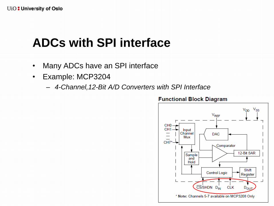
ADCs with SPI interface
• Many ADCs have an SPI interface
• Example: MCP3204
– 4-Channel,12-Bit A/D Converters with SPI Interface
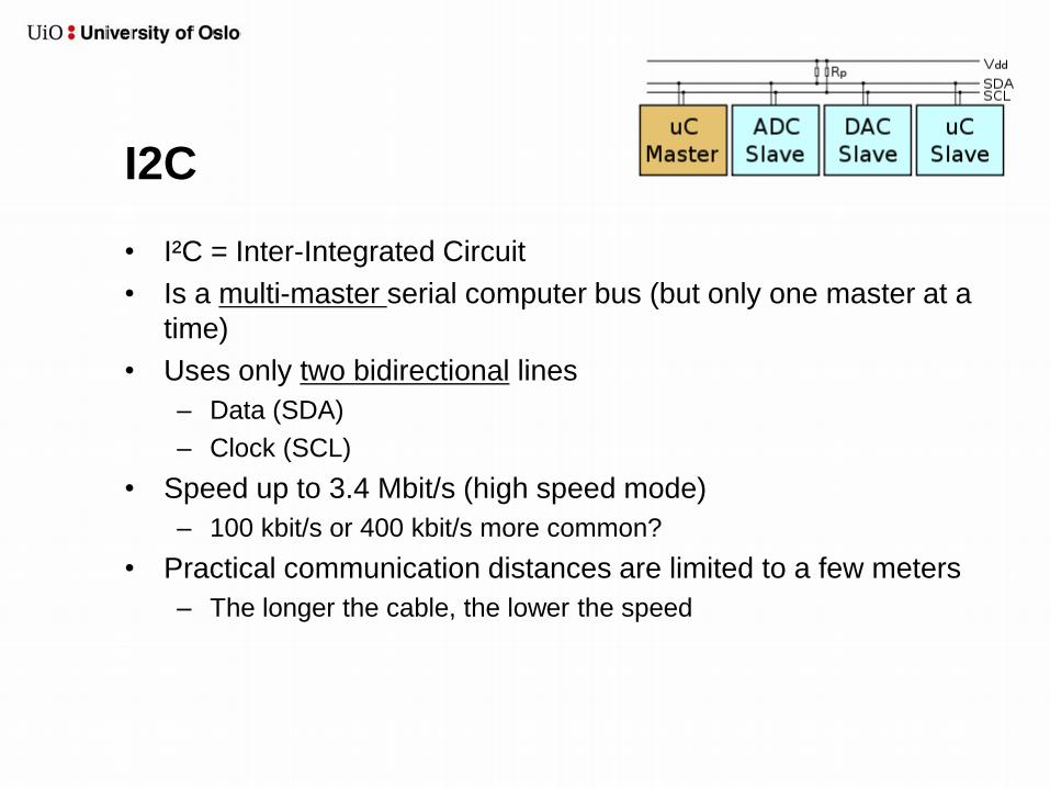
I2C
• I²C = Inter-Integrated Circuit
• Is a multi-master serial computer bus (but only one master at a
time)
• Uses only two bidirectional lines
– Data (SDA)
– Clock (SCL)
• Speed up to 3.4 Mbit/s (high speed mode)
– 100 kbit/s or 400 kbit/s more common?
• Practical communication distances are limited to a few meters
– The longer the cable, the lower the speed

Network Microcontrollers
• Some microcontrollers also have built-in Ethernet support
CAN (Controller Area Network)
• CAN is a multi-master broadcast serial bus standard for connecting
electronic control units.
• CAN bus is designed specifically for automotive applications but now
also used in other areas such as industrial automation.
• Each node is able to send and receive messages, but not
simultaneously.
• The devices that are connected by a CAN network are typically
sensors, actuators, and other control devices. These devices are not
connected directly to the bus, but through a host processor and a CAN
controller.
• Bit rates up to 1 Mbit/s are possible at network lengths below 40 m.
• CAN bus is one of five protocols used in the OBD-II vehicle
diagnostics standard
– On-board diagnostics, or OBD, is an automotive term referring to a
vehicle's self-diagnostic and reporting capability
From wikipedia
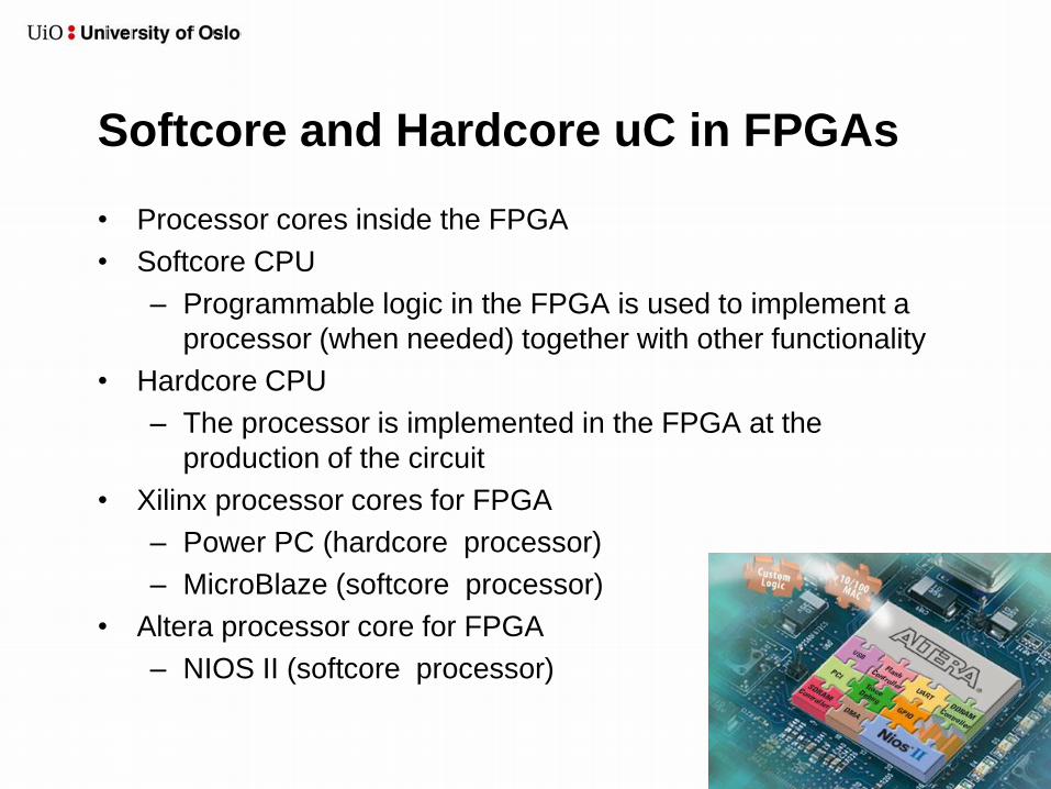
Softcore and Hardcore uC in FPGAs
• Processor cores inside the FPGA
• Softcore CPU
– Programmable logic in the FPGA is used to implement a
processor (when needed) together with other functionality
• Hardcore CPU
– The processor is implemented in the FPGA at the
production of the circuit
• Xilinx processor cores for FPGA
– Power PC (hardcore processor)
– MicroBlaze (softcore processor)
• Altera processor core for FPGA
– NIOS II (softcore processor)
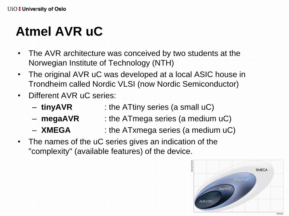
Atmel AVR uC
• The AVR architecture was conceived by two students at the
Norwegian Institute of Technology (NTH)
• The original AVR uC was developed at a local ASIC house in
Trondheim called Nordic VLSI (now Nordic Semiconductor)
• Different AVR uC series:
– tinyAVR : the ATtiny series (a small uC)
– megaAVR : the ATmega series (a medium uC)
– XMEGA : the ATxmega series (a medium uC)
• The names of the uC series gives an indication of the
"complexity" (available features) of the device.
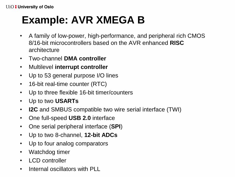
Example: AVR XMEGA B
• A family of low-power, high-performance, and peripheral rich CMOS
8/16-bit microcontrollers based on the AVR enhanced RISC
architecture
• Two-channel DMA controller
• Multilevel interrupt controller
• Up to 53 general purpose I/O lines
• 16-bit real-time counter (RTC)
• Up to three flexible 16-bit timer/counters
• Up to two USARTs
• I2C and SMBUS compatible two wire serial interface (TWI)
• One full-speed USB 2.0 interface
• One serial peripheral interface (SPI)
• Up to two 8-channel, 12-bit ADCs
• Up to four analog comparators
• Watchdog timer
• LCD controller
• Internal oscillators with PLL

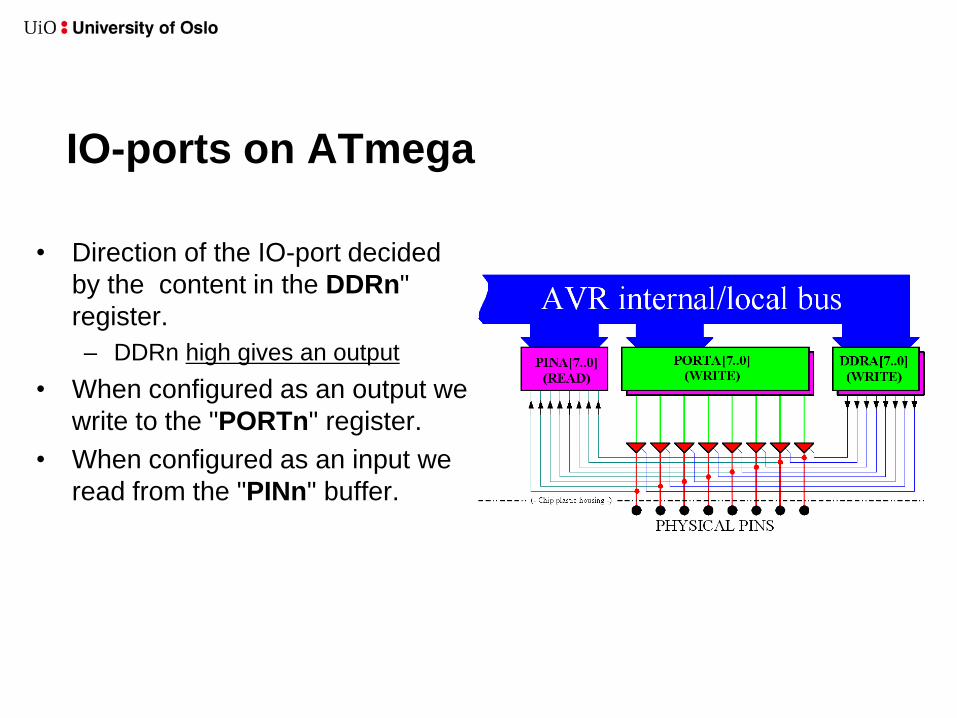
IO-ports on ATmega
• Direction of the IO-port decided
by the content in the DDRn"
register.
– DDRn high gives an output
• When configured as an output we
write to the "PORTn" register.
• When configured as an input we
read from the "PINn" buffer.
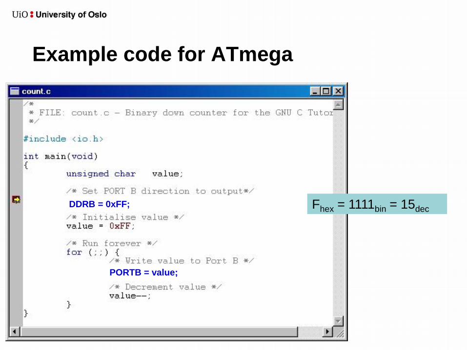
Example code for ATmega
DDRB = 0xFF;
PORTB = value;
Fhex = 1111bin = 15dec
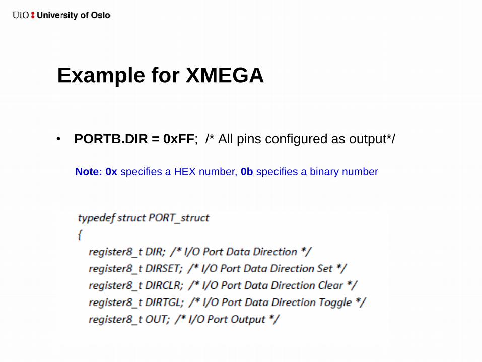
Example for XMEGA
• PORTB.DIR = 0xFF; /* All pins configured as output*/
Note: 0x specifies a HEX number, 0b specifies a binary number
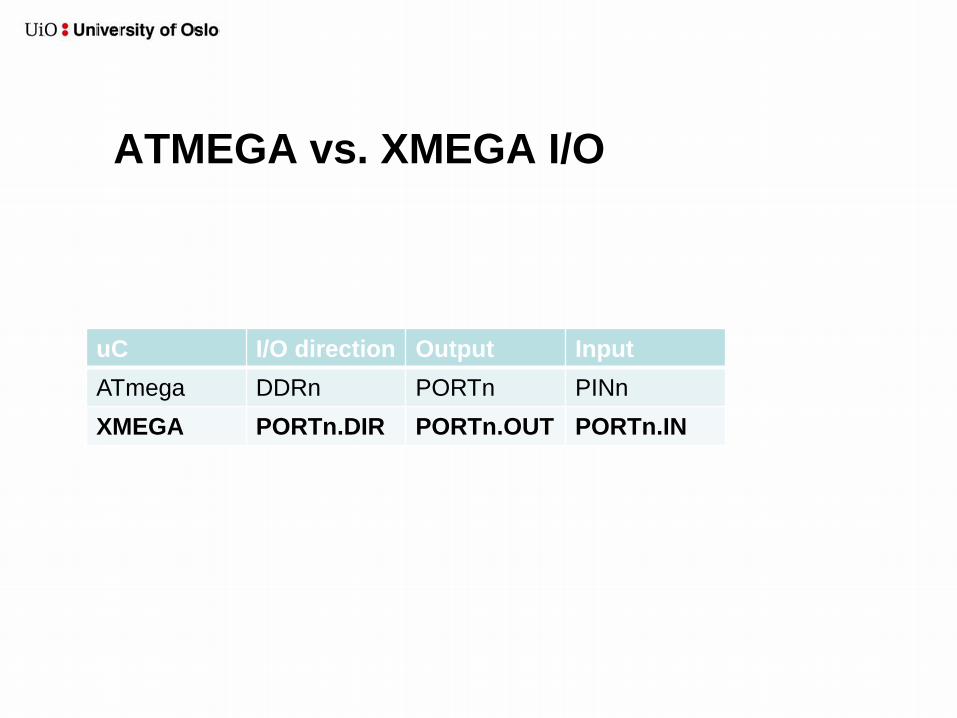
ATMEGA vs. XMEGA I/O
uC I/O direction Output Input
ATmega DDRn PORTn PINn
XMEGA PORTn.DIR PORTn.OUT PORTn.IN

Example code for XMEGA
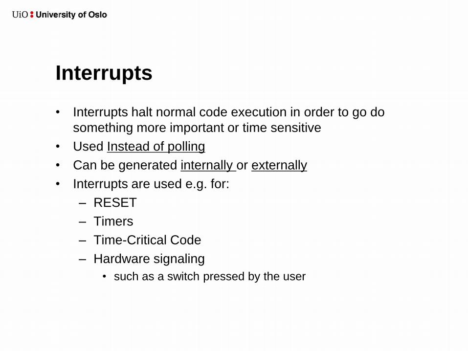
Interrupts
• Interrupts halt normal code execution in order to go do
something more important or time sensitive
• Used Instead of polling
• Can be generated internally or externally
• Interrupts are used e.g. for:
– RESET
– Timers
– Time-Critical Code
– Hardware signaling
• such as a switch pressed by the user

Interrupt on ATmega
By default all interrupts are disabled when the microcontroller is powered-up.
Therefore, the interrupts must be enabled. In addition, global interrupts
must be enabled in the status register.
// Include io.h and interrupt.h
#include <avr/io.h>
#include <avr/interrupt.h>
MCUCR |= (1<<ISC11)|(1<<ISC01); // Interrupt on falling edge
GICR |= (1<<INT1)|(1<<INT0); // Enable interrupt on INT1 and INT0
// Enable global interrupts
sei();
// Global interrupts can be turned off with the following command:
cli()
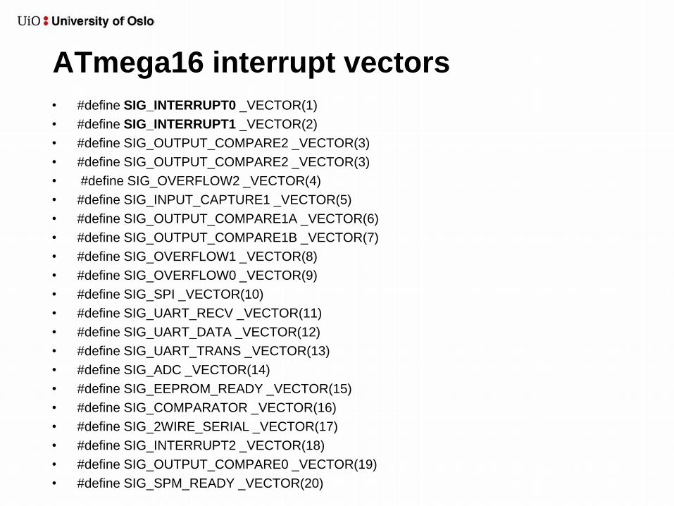
ATmega16 interrupt vectors
• #define SIG_INTERRUPT0 _VECTOR(1)
• #define SIG_INTERRUPT1 _VECTOR(2)
• #define SIG_OUTPUT_COMPARE2 _VECTOR(3)
• #define SIG_OUTPUT_COMPARE2 _VECTOR(3)
• #define SIG_OVERFLOW2 _VECTOR(4)
• #define SIG_INPUT_CAPTURE1 _VECTOR(5)
• #define SIG_OUTPUT_COMPARE1A _VECTOR(6)
• #define SIG_OUTPUT_COMPARE1B _VECTOR(7)
• #define SIG_OVERFLOW1 _VECTOR(8)
• #define SIG_OVERFLOW0 _VECTOR(9)
• #define SIG_SPI _VECTOR(10)
• #define SIG_UART_RECV _VECTOR(11)
• #define SIG_UART_DATA _VECTOR(12)
• #define SIG_UART_TRANS _VECTOR(13)
• #define SIG_ADC _VECTOR(14)
• #define SIG_EEPROM_READY _VECTOR(15)
• #define SIG_COMPARATOR _VECTOR(16)
• #define SIG_2WIRE_SERIAL _VECTOR(17)
• #define SIG_INTERRUPT2 _VECTOR(18)
• #define SIG_OUTPUT_COMPARE0 _VECTOR(19)
• #define SIG_SPM_READY _VECTOR(20)

Example code - Interrupt for ATmega
UDR is the UART’s data register
on ATmega
ISR (SIG_INTERRUPT0)
// interrupt on line INT0
}
data = PINA; // Read data from PORT A
UDR = data; // Send data to the UART
{
ISR = Interrupt Service Rutine
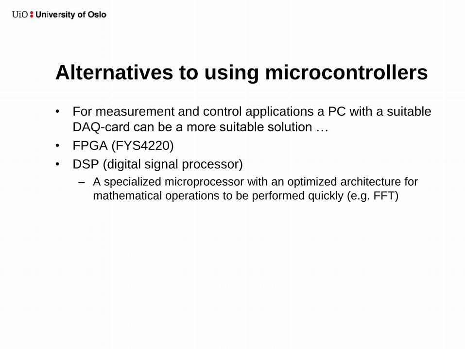
Alternatives to using microcontrollers
• For measurement and control applications a PC with a suitable
DAQ-card can be a more suitable solution …
• FPGA (FYS4220)
• DSP (digital signal processor)
– A specialized microprocessor with an optimized architecture for
mathematical operations to be performed quickly (e.g. FFT)
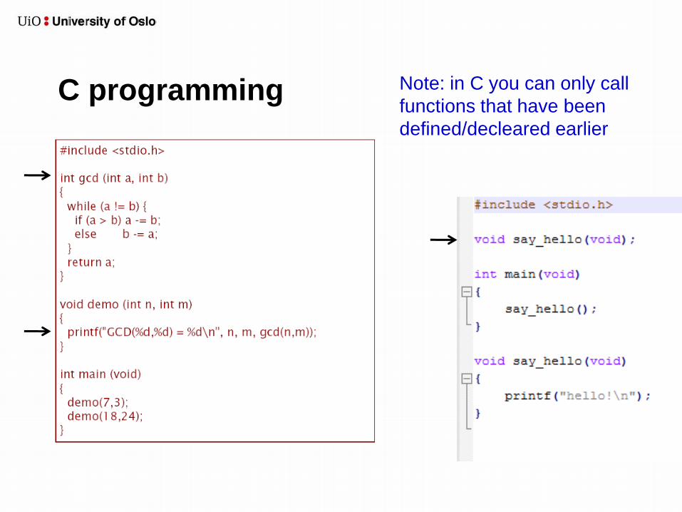
C programming Note: in C you can only call
functions that have been
defined/decleared earlier
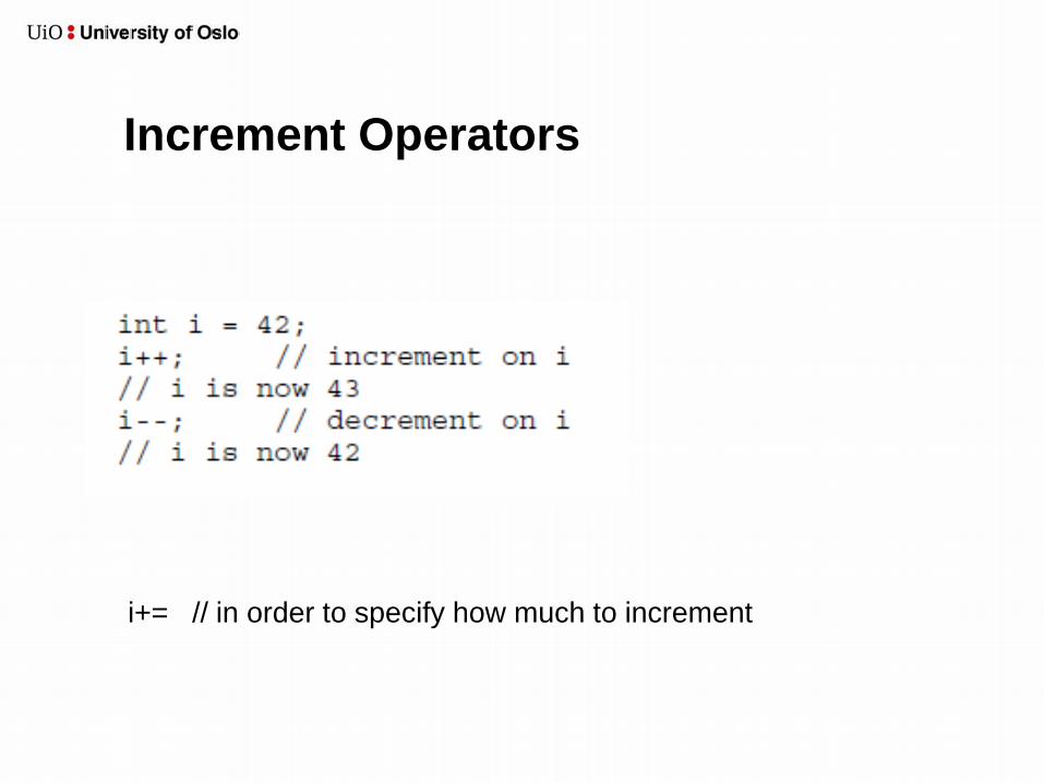
Increment Operators
i+= // in order to specify how much to increment
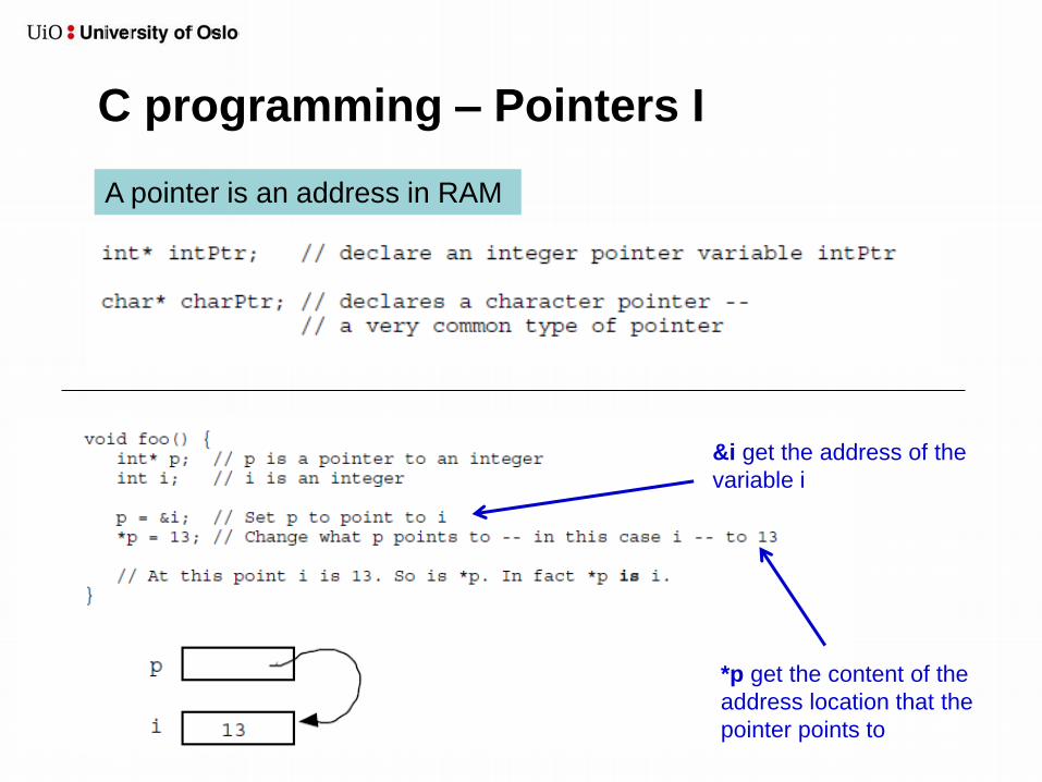
C programming – Pointers I
&i get the address of the
variable i
*p get the content of the
address location that the
pointer points to
A pointer is an address in RAM

C programming – Pointers II

C programming - Memory Management
• Allocate memory : malloc()
• Free used memory : free()
Look out for memory leakage!
More on C-programming
• See EssentialC.pdf
• See http://www.ifi.uio.no/~inf1060/Forelesninger10/


