248
Pilot’s Operating Handbook G-BPEO Take A V I A T I O N . c om

Pilot’s Operating Handbook
G-BPEO
Take A V I A T I O N . c o m

Disclaimer
Take A V I A T I O N . c o m
This pdf scan of the Pilots Operating Handbook (POH) is for information, and to aid flight planning only.
It should not replace reference to the original documents, due to possible updates since publication.
These are available for inspection at Take Flight Aviation Limited on request.

PILOT'S OPERATING HANDBOOK and . .
.. . . ' . :FAA APPROVED AIRPLANEFLICtiT MANUAL . . . .
I CESSNA AlKCKAFT COMPANY I
1 1980 MODEL 152 1 : ' ..
. . THIS DOCUMENT MUST BE &rial N~./S 83775 .:
C+RRIED IN THE AIRPLANE AT ALL TIMES.
, .~ ~ e ~ i i ~ ~ a r i o n ~ . . ~ ~ ~ ~ . . N~.G-BPEO .
This is the Fiighl Manual which lorms pan ol the i Cenillcate ol Aimonhlness loraircrall
THIS HANDBOOK INCLUDES THE I \ .~ATE~IAL FURNISHED TO THE PILOT B Y CAR PART 3 AND CONSTITUTES
.THE FAA APPROVED AIRPLANE FLIGHT MANUAL. /T'C'r- . i . . -. ' . . , . . , , .. . COPIRLGIIT'O 1919 ,,
. , . CESSNA AIKCRAFT COMPANY . . WICHITA, KANSAS, USA
1 JULY 1979

CAA APPROVED CHANGE SHEETS & SUPPLEMENTS FOR UlBODIMENT I N THIS EWNUAL
z 1 ORIGIN AND TITLE
AMM 3 1 170180
APPROVAL AUTHORITY
POSITION I N MANUAL

CESSNA MODEL 152
CONGRATULATIONS
CONGRATULATIONS . . . . Welcome to the ranks of Cessna owners! Your Cessna has been designed and
conrtrucred to give you the most in periormance.economy,and comiort. It is our desire that you will find flying i t , either lor business or pleasure, a pleasant and profitable experience.
This Pilot's Operating Handbook has been prepared as a guide to help you get the most pleasure and utility lrom your airplane. It contains information about your Cessna's equipment, operating procedures, and performance; and suggestions lor i ts servicing and care. We urge you to read it f r o r cover to cover, and to refer to it frequently.
Our interest in your flying pleasure has not ceased with your purchase o f a Cerma. World-wide, the Cessna Dealer Organization backed by the Cesrna Customer Services Department stands ready to serve you. The following services are offered by most Cesma Dealers:
THE CESSNA WARRANTY,which provides coverage for part sand labor,isavailableat Cessna Dealers wor1dwide:Specific benefits and provisions of warranty, plus other imporrant benefits for you, are contained in your Customer Care Program book, supplied with your airplane. Warranty service isavailable to you at authorized Cessna Dealers throughout the world upon presentation o f your Customer Care Card which establishes your eligibility under the warranty.
FACTORY TRAINED PERSONNEL lo provide you with courteous expert service
FACTORY APPROVED SERVICE EQUIPMENT to provide you efficient and accurate workmanship.
A STOCK OF GENUINE CESSNA SERVICE PARTS on hand when you need them.
ThE .ATE>T ALTIIOKITATILE IhFOK%tATlOh FOK 5EKVIC.hC CLSShA h.K- PLAXES. ,Ince Cesrna Oe~.er rh3re~. I JI t r w SerbKe M ~ # w 3 ! 5 d l d Par5 C~ldlo#s hc;,t cdrrrnt 1,) Scr. cc .ellerr arid )err ce \en$ Lzller5. p ~ d . h e U b) Ce,rn3 A.rcrdlt Company.
We urge a l l Cesrna owners to use the Cessna Dealer Organization to the fullest.
A current Cessna Dealer Directory accompanies your new airplane. The Directory i s revised frequently. and a current copy can beobtained lrom your Cessna Dealer. Make your Directory one o l your cross-country flight planning aids; a warm welcome awaits yo,, at every Cessna Dealer.

PERFORMANCE- SPECIFICATIONS
CESSNA MODEL 152
PERFORMANCE - SPECIFICATIONS
'SPEED: Maximum a t Sea Level . . . . . . . . . . . . . . . . . . . . 110 KNO'i'S Cruise. 75% Power at 8000 Ft . . . . . . . . . . . . . . . 107 K N O T S
CRUISE: Recommended lean mixture with fuel allowance f a r engine start . taxr, takeoff, olinlb and 45 minules reserve.
75% Power a t 8000 Ft . . . . . . . . . . . . . . . . Rirnga 320 NM 24.5 Gvilons Usable Fuel Time 3.1 HRS
75% Power a t 8000 Ft . . . . . . . . . . . . . . . . .Range 545 NM 37.5 Gallons Usable Fuel Time 5.2 HRS
Maximum Range a t 10.000 Ft . . . . . . . . . . . . .Range 415 NM 24.5 Gallons Usable Fuel Time 5.2 HRS
Maximum Range a t 10.000 Ft . . . . . . . . . . . . . .Range 690 NM 37.5 Gallons Usable Fuel Time 8.7 HRS
RATE O F CLIMB AT SEA LEVEL . . . . . . . . . . . . . . . . 715 FPM SERVICE CEILING . . . . . . . . . . . . . . . . . . . . . . . 14.700 F7 TAKEOFF PERFORMANCE:
Ground Roll . . . . . . . . . . Torn1 Distance Over 50-Ft Obstnole
LANDING PERFORMANCE: Ground Roll . . . . . . . . . . Total Distance Over 50-Ft Obstacle
STALL. SPEED (CAS): F l aos Uo. Power Off . . . . labs ~ b w n Power orf .
R a m p . . . . . . . . Takeoff or Landing . . . .
STANDARD EMFTY WEIGHT. 152 . . . . . . . . . . . . 152 I1 . . . . . . . . . . .
MAXIMUM USEFUL LOAD: 152 . . . . . . . . . . . . . 152 11 . . . . . . . . . . .
BAGGAGE ALLOWANCE . . . WING LOADING: PoundsISq F t POWER LOADING: PoundsIHP FUEL. CAPACITY: Total
S t anda rdTanks . . . . . . Lonlr Ranre Tanks . . . .
48 KNOTS 43 KNOTS
1675 LBS 1670 LBS
1109 LBS 1142 LBS
566 LBS 533 LBS 120 LBS 10.5 15.2
26 GAL.. 39 GAL. 6 OTS ~ ~
ENGINE: Avo0 Lycoming . . . . . . . . . . . . . . . . . . . . 0-235-1.2C I10 BHP a t 2550 RPM
PROPELLER: Fixed Pitch. Diameler . . . . . . . . . . . . . . . 69 IN.
'Speed performance i s shown fo r an ai rp lane equipped with optional speed fairings. w h x h increase the speeds by approximately 2 knots. There is a. correspand~ngdif ferenco in range. while a l l other performance f igures are unchanged when speed f a m n g s are installed.
ii 1 July 1979

CESSNA MODEL 152
COVERAGEIREVISIONSI LOG OF EFFECTIVE PAGES
COVERAGE !
The Pilot's Operating Handbook in !he amplane at the time of delivery from Cerrna Aircrafl Company conrainr information applicable to the 1900 Model 152 airplane dirognaled by the ~e r fa l number and registration number shown on the Title Page 01 this handbook.
I REVISIONS
Changer andior additions l o this handbook will be covered by revirionr published by Cerrna Aircralt Company. lhere revirionr aie distributed to a l l Cerrna Dealerr and to ownerr u i U. 3. Regirwred aircralt according to FAA records at the time of revirion irruance.
Revirionr ~ h a u l d be ezarnined immediately upon receipt and incorporaled in this handbook.
NOT€
I It is the rerponribilily of the owner to nminlain (hi; handbookina current status when i t is being used for opentional purposes.
Ownerr rhouldcontacrtheir Cerrna Dealer whenever the revision status of their handbook ir in question.
A revision bar will exlend the lul l length 01 new or revired lext and/orillurtrationradded on new or presently existing pager. This bar will be located adjacenl to the applicable revired area an the ouler margin o l (he page.
All revised pager will carry the revision number and date on the applicable page.
The following LogolEfiectivePagerprovirlerthedaterof irsuefororiginalandrevired pages.and . a listing of all pager in the handbook. Pager affected by rhe curtent revision are indicated by a n asterisk (-1 preceding the pager listed.
LOG OF EFFECTIVE PAGES , i
Oater o i issue for original and revired pager are: Original ..................... I July 1979 Revision 1 ............. 31 March 1983
Date
1 July 1979 Revision 1 - 31 March 19831D1170-L-13PH-RPC-2300-5/83
I Title .............................. 1 July 1979 '5-14 thru 5-18 ........... J I March 1981
1 luly 1979 5-19 ............................. I luly 1979 I luly 1979 1 I d y 1979
March 1983 I luly 1979 iv ................................ I luly 1979 1 l d y 1979
................... .................. 1-1 lhru 1-2 1 Iuly 1979 6-3 thru 6.20 1 luly 1979 '1-3 tliw 1-4 ........... 31 March I903 7.1 thru 7-37 1 luly 1979 ..................
7-38 Blank ..................... I luly 1979 1 luly 1979 I luly 1979 I luly 1979
.. March 1983 8-12 thru 8.17 ................ I luly 1979 8-10 Blank ..................... I luly 1979
'9-1 t h r ~ 9-2 .............. 31 March 1983 4-11 3 ................ 1 )illy 1'179 4~24 Bl.~nk ..................... I IC);" 197,) NOTE 5-1 .......................... I IuIy l'li'l Relw to Section 9 Table oi Contents ior 5;> Blmk ...................... I Iklv lv7~1 rupplcmentr applicable lo optiorral ryr- 5 - 1 thru 5-13 .................. I lulv 1 ~ 1 7 ~ terns.
I !
iii '
I

TABLE O F CONTENTS CESSNA ,MODEL 152
TABLE OF C0NT;ENTS
SECTION
GENERAL.. . . . . . . . . . . . . . . . . . . . . . . . . . . . . 1
LIMITATIONS.. . . . . . . . . . . . . . . . . . . . . . . . 2
EMERGENCY PROCEDURES.. . . . . . . . . . . 3
N O R M A L PROCEDURES.. . . . . . . . . . . . . . 4
PERFORMANCE.. . . . . . . . . . . . . . . . . . . . . 5 : WEIGHT & BALANCE/
EQUIPMENT LIST . . . . . . . . . . . . . . . . . 6
AIRPLANE & SYSTEMS DESCRIPTIONS . . . . . . . . . . . . . . . . . . . 7
AIRPLANE HANDLING, SERVICE & MAINTENANCE . . . . . . . . [I:
SUPPLEMENTS (Opt ional Systems Descript ion & Operat ing Procedures) . . . . . . . . . . 9
1 July 1979

SECTION 1 GENERAL
SECTION I GENERAL
TABLE OF CONTENTS Page
. . . . . . . . . . . . . . Three View
. . . . . . . . . . . . . . Introduction . . . . . . . . . . . . Descriptive Data
Engine . . . . . . . . . . . . . . Propeller . . . . . . . . . . . . . Fuel . . . . . . . . . . . . . . . . Oil . . . . . . . . . . . : . . . . Maximum Certificated Weights . . . Standard Airplane Weights . . . . . Cabin And Entry Dimensions . . . . Baggage Space Dimensions . . . . .
t-. .. Specific Loadings . . . . . . . . . Svmbols . Abbreviations And Terminoloev
" General Airspeed Terminology ~ n d ' ; J ~ m b o l s . . . . . Meteoroloeical Terminolo~~y . . . . . . . . . . . . . - .. Engine Power Terminology . . . . . . . . . . . . . . Airplane Performanqe And Flight Planning Terminology Weight And Balance Terminology . . . . . . . . . . .
1 July 1979

SECTION 1 GENEFiAL
CESSNA MODEL 152
2. M..lrn"rn h.,gh, .no- *I,h no,. g a l , daurencd. .ti l l r n 3"d no* m u , Con- "1" inllaltd and ilo.hln9 a x o n i".l.ll.d
tW.,d wing tip, 8, 2d' - B".
.-I
Figure 1-1. Three View
1 July 1979

CESSNA SECTION 1 ' MODEL 152 GENERAL
INTRODUCTION This handbook contains 9 sections, and includes the material required
to be furnished to the pilot by CAR Par t 3. I t a l so contains supplemental data supplied by Cessna ~ i r c r a f t Company
Section 1 provides basic data and information of general interest. It a lso contains definitions o r explanations of symbols. abbreviations. and terminology commonly used.
DESCRIPTIVE DATA ENGINE
Number of Engines: 1. Engine Manufacturer: Avco Lycoming. Engine Model Number: 0-235-L2C. Engine Type: Normally-aspirated. direct-drive. air-cooled. horizontally-
opposed, carburetor equipped. four-cylinder engine with 233.3 cu. in. displacement.
Horsepower Rating and Engine Speed: 110 rated BHP at 2550 RPM.
I - PROPELLER
Propeller Manufacturer: McCaulev Accessorv Division. ~ r o p e l l e r Model Number: 1 ~ 1 0 3 / k ~ 6 9 5 8 . - - ' Number of Blades: 2. Propeller Diameter. Maximum: 69 inches.
Minimum: 67.5 inches Propeller Type: Fixed pitch.
FUEL
Approved Fuel Grades (and Colorsl: lOOLL Grade via ti on Fuel ( ~ i " e ) . 100 (Formerly 1001 130) Grade Aviation Fuel (Green).
NOTE
Isopropyl alcohol o r ethyiene glycol monomethyl ether m a y be added to the fuel supply. Additive concentrations sha l l not exceed 1% for isopropyl alcohol o r .15% for ethylene glycol monomethyl ether. Refer to Section 8 for additional information.
1 July 1979 Revision 1 - 31 March 1983

I THlS DATA IPPLICABLE ONLV TO AIRP!.ANES WITH LYCOMlNG 0 . Z 1 5 U C W b l N T . SOR AIRPLANES WlTH ENGlNE WDCIED TO 0.215-N1C. REFER TO OATA IN SECTION 9 SUPPLEMENT.
SECTION 1 CESSNA GENERAL MODEL 152
Fuel Capacity: Standard Tanks:
'Total Capacity: 26 gallons. Total Capacity Each Tank: 13 gallons Total Usable: 24.5 gallons.
Long Range Tanks: Total Capacity: 39 gallons. Total Capacity Each T a n k 19.5 gallons Total Usable: 37.5 gallons.
NOTE
Due to cross-feeding between fuel tanks. t h , tanks should be re-topped after each refueling to assure maximum capacity.
OIL
Oil Grade (Specification): MIL-L-6082 Aviation Grade Straight Mineral Oil: 'Jse to reolenish .*
supply during Iirst 25 hours and at the first 25-hour oil change. Continue to use until a total of 50 hours h a s acc:rmulated o r oil :
consumption has stabilized.
NOTE - I
The airplane was delivered from the factory with a wr ro - sion preventive aircraft engine oil. Th i s oil shouli! be drained after the first 25 hou r s of operation.
MIL-L-22851 Ashless Dispersant Oil: This oil mus t be used . 4 e r first 50 hours o r oil consumption h a s stabilized.
Recommended Viscosity for Temperature Range: MIL-L-6082 Aviation Grade Straight Mineral Oil:
SAE 50 above 16% (60°F). SAE 40 between -l°C (30°F) and 32% (90DF). SAE 30 between -1s0C (O°F) and 21°C (70°F). SAE 20 below -lZ°C (lO°F).
MIL-L-22851 Ashless Dispersant Oil: SAE 40 o r SAE 50 above 16'C 160"FI. SAE 40 between -19C (30-F) and 32°C (90-F). SAE 30 o r SAE 40 between -lE°C (Oo.FI and 21°C (70°F), SAE 30 below -12°C (lO°F).
Oil Capacity: Sump: 6 Quarts. Total: 7 Quarts (if oil filter installed)
1 July 1979 Revision 1 - 31 March 1983
CESSNA MODEL 152
SECTION 1 GENERAL
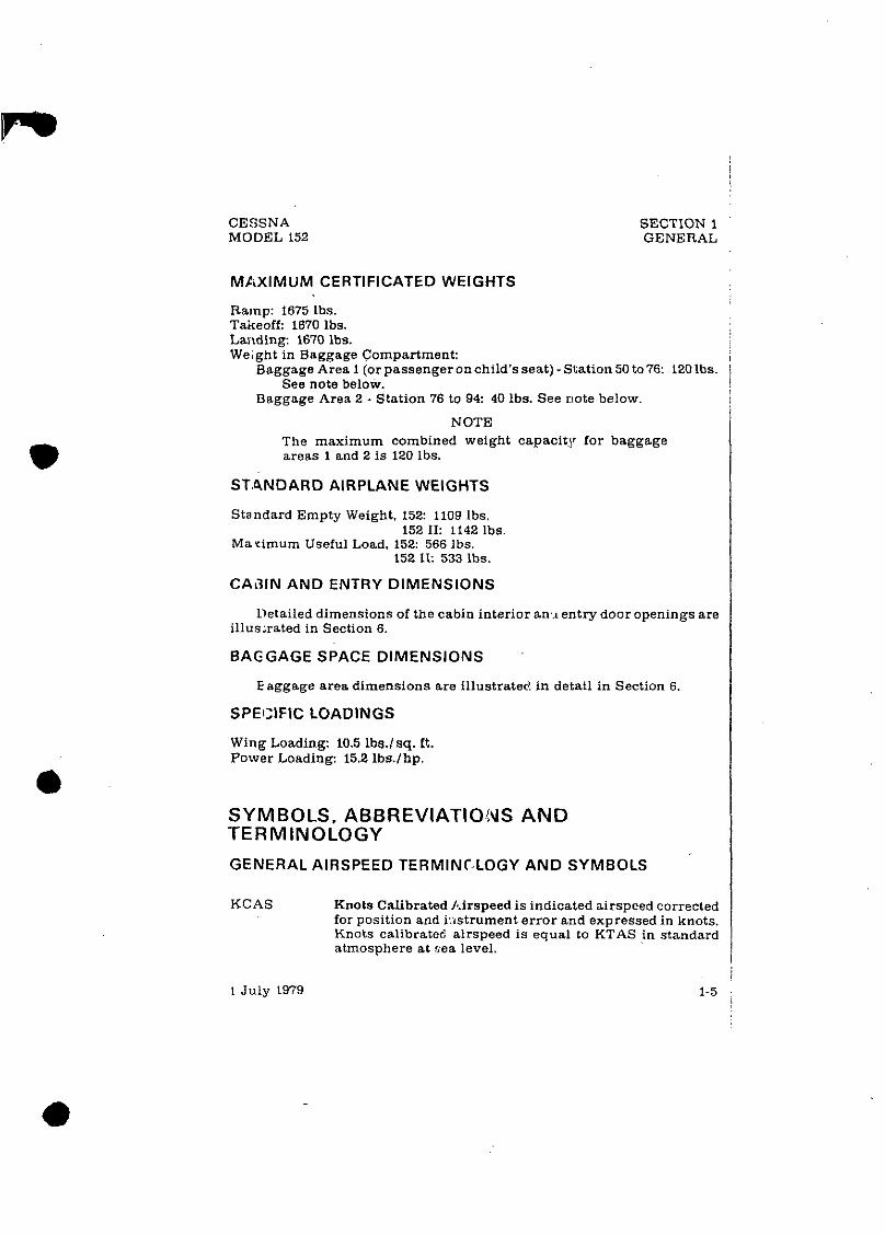
MAXIMUM CERTIFICATED WEIGHTS
Ramp: 1675 lbs. Takeoff: 1670 lbs. La~lding: 1670 lbs. Weight in Baggage Compartment:
Baggage Area 1 (or passenger on child's seat) - Station 50 to 76: 120 lbs. See note below.
Baggage Area 2 - Station 76 to 94: 40 lbs. See uote below.
NOTE The maximum combined weight capacit,y for baggage areas 1 and 2 i s 120 lbs;
Standard Empty Weight. 152: 1109 lbs. 152 11: 1142 1bs
Ma vimum Useful Load. 152: 566 lbs. 152 11: 533 lbs.
CAAIN AND ENTRY DIMENSIONS
Detailed dimensions of the cabin interior an,., entry door openings are illusxated in Section 6.
BAGGAGE SPACE DIMENSIONS
E aggage area dimensions are illustratec! in detail in Section 6.
SPECIFIC LOADINGS
Wing Loading: 10.5 1bs.lsq. ft. Power Loading: 15.2 1bs.lhp.
SYMBOLS. ABBREVIATIOC\IS A N D TERMINOLOGY
GENERAL AIRSPEED TERMINC,LOGY AND SYMBOLS
KCAS Knots Calibrated /c.irspeed is indicated airspeed corrected for position and i,xstrument error and expressed in knots. Knots calibrate6 airspeed is equal to KTAS in standard atmosphere at sea level.
1 July 1979

SECTION 1 GENERAL
KIAS
KTAS
v~
'FE
'NO
'NE
v s o
V x
'Y
- CESSNA
MODEL 152
Knots Indicated Airspeed is the speed shown on the airspeed indicator and expressed in knots.
Knots True Airspeed is the airspeed expressed in knots relative to undisturbed air which i s KCAS corrected for altitude and temperature.
Manuevering Speed is the maximum speed at which you may use abrupt control travel.
Maximum Flap Extended Speed i s the highest speed permissible with wing flaps in a prescribed extended position.
Maximum Structural Cruising Speed is the speed that should not be exceededexcept in smooth air. then only with caution.
Never Exceed Speed i s the speed limit that may not be exceeded at any time.
Stalling Speed or the minimum steady flight speed at which the airplane is controllable.
Stalling Speed or the minimum steady flight speed at which the airplane i s controllable in the landing configu- ration at the most forward center of gravity.
Best Angle-of-Climb Speed is the speed which results in the greatest gain of altitude in a given horizontal distance.
Best Rate-of-Climb Speed is the speed which results in the greatest gain in altitude in a given time.
METEOROLOGICAL TERMINOLOGY
OAT Outside Air Temperature is the free air static temperature. It is expressed in either degrees Celsius or degrees Fah- renheit.
Standard Standard Temperature i s 15'C at sea level pressure alti- Tempera- tude and decreases by Z°C for each 1000 feet of altitude. I
ture -,
Pressure Pressure Altitude i s the altitude read from an altimeter Altitude when the altimeter's barometric scale has been set to 29.92
inches of mercury (1013 mb).

SECTION 1 GENERAL
CESSNA MODEL 152
by its arm. (Moment divided by the constant 1OOOisusedin this handbook to simplify balance calculations by reduc- ing the number of digits.)
Center of Center of Gravity i s the point at which an airplane. or Gravity equipment, would balance if suspended. Its distance from (C.G.) the reference datum is found by dividing the total moment
by the total weight of the airplane.
C.G. Center of Gravity A m is the arm obtained by adding the Arm airplane's individual moments and dividing the sum by
the total weight.
C.G. Center of Gravity Limits are the e h e m e center of gravity Limits locations within which the airplane must be operated at a
given weight. "
Standard Standard Empty Weight is the weight of a standard air- Empty plane. including unusable fuel. full operating fluids and Weight full engine oil.
Basic Empty Basic Empty Weight i s the standardempty weight plus the Weight weight of optional equipment.
Useful ~ s e f u l ~ o a d is the difference between ramp weight andthe Load basic empty weight.
Maximum Maximum Ramp Weight i s themaximum weight approved Ramp for ground maneuver. (It includes the weight of start, taxi weight and~runup fuel.)
Maximum Maximum Takeoff Weight i s the maximum weight ap- Takeoff proved for the start of the takeoff run. Weight
Maximum Maximum Landing Weight i s the maximum weight ap- Landing proved for the landing touchdown. Weight
Tare Tare is the weight of chocks, blocks, stands. etc. used when weighing an airplane, and is included in the scale read- ings. Tare is deducted from the scale reading to obtain the actual (net) airplane weight.
1 July 1979
CESSNA MODEL 152
SECTION 1 (iENERAL
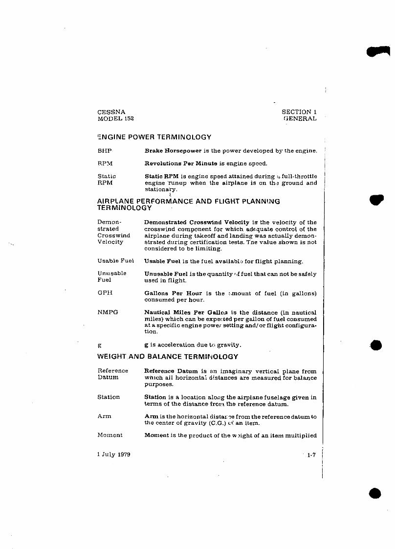
'ENGINE POWER TERMINOLOGY
BHP Brake Horsepower is the power developed by the engine.
RPM Revolutions Per Minute is engine cpood.
Static Static RPM is engine speed attained during :. full-throttle RPM engine runup when the airplane is on the ground and
stationary. i
AIRPLANE PERFORMANCE AND FLIGHT PLANNl,iUG TERMINOLOGY
Demon- strated Crosswind Velocity
Usable Fuel
Unusable Fuel
GPH
NMPG
g
Demonstrated Crosswind Velocity i s the velocity of the crosswind component for which adequate control of the airplane during takeoff and landing was actually demon- strated during certification tests. Tne value shown is not considered to be limiting.
Usable Fuel i s the fuel availabli for flight planning
Unusable Fuel is the quantity r e f fuel that can not be safely used in flight.
Gallons Per Hour i s the :.mount of fuel (in gallons) consumed per hour.
Nautical Miles Per Gallon is the distance (in nautical miles) which can be expected per gallon of fuel consumed at a specific engine power setting andlor flight configura- tion.
g is acceleration due to gravity.
WEIGHT AND BALANCE TERMlFiOLOGY
Reference Reference Datum is rin imaginary vertical plane from Datum whlch all horizontai distances are measured for balance
purposes.
Station Station is a location along the airplane fuselage given in terms of the distance f r o n the reference datum.
Arm Arm is the horizontal distaroe from the referencedatum to the center of gravity (C.G.) cZ an item.
Moment Moment i s the product of the w 3ight of an item multiplied
1 July 1979 1-7

CESSNA MODEL 152
SECTION 2 LIMITATIONS
SECTION 2 LIMITATIONS
THIS DATA APPLICABLE ONLY TO AIRPLANES WlTH LYCOMING 0-235.UC ENGINE . FOR AIRPLANES WITH ENGINE MODIFIED TO 0.235.NZC . REFER TO DATA I N SECTION 9 SUPPLEMENT .
TABLE OF CONTENTS
. . . . . . . . . . . . . . . . . . . . . . . . Introduction . . . . . . . . . . . . . . . . . . . Airspeed Limitations
. . . . . . . . . . . . . . . . Airspeed Indicator Markings . . . . . . . . . . . . . . . . . . Power Plant Limitations
Power Plant Instrument Markings . . . . . . . . . . . . . . . . . . . . . . . . . . . . . . . . . . . . Weight Limits
Center Of Gravity Limits . . . . . . . . . . . . . . . . . . . . . . . . . . . . . . . . . . . . . . . Maneuver Limits
Flight Load Factor Limits . . . . . . . . . . . . . . . . . Kinds Of Operation Limits . . . . . . . . . . . . . . . . . Fuel Limitations . . . . . . . . . . . . . . . . . . . . . . Other Limitations . . . . . . . . . . . . . . . . . . . . .
. . . . . . . . . . . . . . . . . . . . Flap Limitations Placards . . . . . . . . . . . . . . . . . . . . . . . . .
1 July 1979 Revision 1 . 31 March 1983
I Page
. 2-3
. 2-3
. 2-4
. 2-4
. 2-5 2-5
. 2-5
. 2-6
. 2-6
. 2-6
. 2-7
. 2-7
. 2-7
. 2-8
2-11(2-2 blank)

1 V N ~ 1 Never Exceed Speed 1 1 I !io not exceed this speed in any operation. I
CESSNA MODEL 152
SECTION 2 LIMITATIONS
INTRODUCTION
Section 2 includes operating limitations, instrument markings. and basic placards necessary for the safe operation of the airplane, its engine. standard systems and standard equipment. The limitations included in this section and in Section 9 have been approved by the Federal Aviation Administration. Observance of these operating limitations 1s required by Federal Aviation Regulations.
NOTE
Refer to Section 9 of this Pilot's Operating Handbook for amended operating limitations, operating proct?dures. performance data and other necessary informxion for airplanes equipped with specific options.
Your Cessna is certificated under FAA Type Certificate No. 3A19 as Cessna Model No. 152.
AIRSPEED LIMITATIONS
Airspeed limitations and their operational significance are shown in figure 2-1.
SPEED KCAS KlAS 11 REMARKS
I
I I Maximum Structural 11 1 ( Do not exceed this speed Cruising Speed
1 1 0 8 1 I except in smooth air, and then only with caution. I
VA ~a"ewerimi~peed:- ~l ~ . ~p -p~~pl 1670 Pounds Do not make full or abrupt 15'20 Pounds control movements above 1350 Pounds this speed. -
VFE Maximum Flap Extended Do not exceed this speed Speed 87 with flaps down. - Maximum Window Open Do not exceed this speed with Speed 145 1451 windows open.
Figure 2-1. Airspeed Limitations
1 July 1979

SECTION 2 LIMITATIONS
CESSNA MODEL 152
AIRSPEED INDICATOR MARKINGS Airspeed indicator markings and their color code significance a n
shown in figurc 2-i?.
White Arc
MARKING
Green Arc
Full Flap Operating Range. Lower l imit is maximum weight VS in
0 . . landing configuration. Upper l1m11 ir maximum speed permisriblo with flaps extended.
Normal Operating Range. Lower limit is maximum weight VS at m o n forward C.G. with flaps retracted. Upper limit is maximum structural cruising speed.
KlAS VALUE OR RANGE
Yellow Arc 1 111 - 149 1 Ope~ations must be conducted with caultan and onlv in smooth air.
SlGNlFlCANCE
I Red Line I 149 I Maximum speed for all operations. L 1 I
Figure 2-2. Airspeed Indicator Markings
POWER PLANT LIMITATIONS Engine Manufacturer: Avco Lycoming. Engine Model Number: 0-235-L2C. Engine Operating Limits for Takeoff and Continuous Operations:
Maximum Power: 110 BHP rating. Maximum Engine Speed: 2550 RPM.
NOTE
The static RPM rmge at lull throttle (carburetor heat off and rnlxture Leaned to maximum RPM) 1s 2280 to2380 HPM.
Maximum Oil Temperature: 245°F (118°C). Oil Pressure. Minimum: 25 osi.
Maximum: 115 psi. Propeller Manufacturer: McCaulev Accessorv Division. ~ r o b e l l e r Model Number: 1~103 / ' iC~6958 . . Propeller Diameter. Maximum: 69 inches.
Minimum: 67.5 inches.
1 July 1979

CIVIL AVIATION AUTHORITY I CAA CHANGE SHEET NO 1 ISSUE 1 to the CESSNA MODEL 152 1980 PILOT'S OPERATING
a HANDBOOK AND FAA APPROVED AIRPLANE FLIGHT MANUAL Dl170 (CAA Ref: 524/39295)
Serial No: Registration Mark:
bIJDI1IONAL LIMITA'I'IONS AND INFORMI\TION FOR IlNlTED KlNGDOM CERI'IFICAI'ION
The limitations and information contained herein either supplement or, in the case of conflict, override those in thefli~~ht manual.
SECTION 2 - POWER PLANT LIMITATIONS
W e n a Sensenich 72-CKS6-0-56 propeller is fitted the following additional limitations shall apply in order for the aircraft to comply with the Air Navigation (Noise Certification) Order 1990:
I. The propeller tachometer shall be marked with a green line, or the top of the peen arc shall fmish, at 2440 rpm and this shall be referred to as the highest rpm setting in the normal operating range.
2. The green l i e at 2440 rpm marks the highest power that may be used in the normal operating range, and apart from TAKE-OFF FLIGHT PATH, EN-ROUTE CLIMB WHEN NOT YET CLEAR OF OBSTACLES, BAULKED APPROACH, AND IN ANY EMERGENCY, this engine power shall not be exceeded.
I To be inserted in theflighr manunlfacin~ Pa@ 2-4 and the CAA revisionr 1
Page 1 of 1

CESSNA MODEL 152
SECTION2 i LIMITATIONS
POWER PLANT INSTRUMENT MARKINGS
Power plant instrument markings and their color code significance are shown in f igure 2-3.
INSTRUMENT
Tachometer: Sea Level 4000 Feet 8000 Feet
Oil Temperature I Oil Pressure I 25 psi
Fuel Quantity E 10.75 Gal. Unurablt
Each Tank)
Suction -. .
GREEN ARC
NORMAL OPERATING
1900 - 2350 RPM 1900 - 2450 RPM 19W - 2550 RPM
60 - 90 psi
4.5 - 5.4 in. Hg
Figure 2-3. Power Plant Instrument Markings
WEIGHT LIMITS ,
Maximum Ramp Weight: 1675 lbs. Maximum Takeoff Weight: 1670 ibs. Maximum Landing Weight: 1670 ibs. Maximum Weight i n Baggage Compartment:
Baggage Area 1 (orpassengeronchild'sseat) - Station 50 to76: 120lbs. See note below.
Baggage Area 2 - Station 76 to 94: 40 ibs. See note below.
NOTE The maximum combined weight capacity for baggage areas 1 and 2 i s 120 ibs. '
CENTER OF GRAVITY LIMITS
Center of Gravity Range: Forward: 31.0 inches aft of datum at 1350 lbs. or less. with straight line
variation to 32.65 inches aft of datum a t 1670 lbs.
RED LlNE
MAXIMUM LIMIT
2550 RPM
245OF
11 5 psi
. -.
- - -

SECTION 2 LIMITATIONS
CESSNA MODEL 152
Aft: 36.5 inches aft of datum at all weights Reference Datum: Front face of firewall.
MANEUVER LIMITS This airplane is certificated in the utility category and isdesigned for
limited aerobatic flight. In the acquisition of various certificates such as commercial pilot and flight instructor, certain maneuvers are required. All of these maneuvers are permitted in this airplane.
No aerobatic maneuvers are approved except those listed below:
MANEUVER RECOMMENDED ENTRY SPEED'
Chandelles . . . . . . . . . . . . . . . .95 knots Lazy Eights . . . . . . . . . . . . . . . . . . . . . .95 knots Steep Turns . . . . . . . . . . . . . . . . . . . . . .95 knots Spins . . . . . . . . . . . . . . . . . . Use Slow Deceleration Stalls (Except Whip Stalls) . . . . . . . . Use Slow Deceleration
'Higher speeds can be used if abrupt use of the controls is avoided
The baggage compartment and/or child's seat must not be occupied during aerobatics.
Aerobatics that may impose high loads should not be attemuted. The important thing to bear in mind in fckght maneuvers is that the airplane is clean in aerodynamic des~gn and wlll bulld up speedaulcklv wlth thenose down. Proper speed control is an essential iequirement f i r execution of any maneuver. and care should always be exercised to avoid excessive speed which in turn can impose excessive loads. In the execution of all maneuvers, avoid abrupt use of controls.
FLIGHT LOAD FACTOR LIMITS
Flight Load Factors: 'Flaps Up: t4.4g, -1.76g 'Flaps Down: +3.5g
'The design load factors are 150% of the above, and in all cases, the structure meets or exceeds design loads.
KINDS OF OPERATION LIMITS The airplane is equipped for day VFR and may be equipped for night
VFR andlor IFR operations. FAR Part 91 establishes the minimum required instrumentation and equipment for these operations. The refer-
2-6 1 July 1979

CESSNA MODEL 152
SECTION 2 LIMITATIONS 8
ence to types of flight operations on the operating limitations placard reflects equipment installed at the time of Airworthiness Certificate issuance.
Flight into known icing conditions is prohibited.
FUEL LIMITATIONS 2 Standard Tanks: 13 U. S. gallons each.
Total Fuel: 26 U .S. gallons. Usable Fuel (all flight conditions): 24.5 U.S. gallons. Unusable Fuel: 1.5 U.S. gallons.
2 tong Range Tanks: 19.5 U.S. gallons each. Total Fuel: 39 U. S. gallons. Usable Fuel (al1,flight conditions): 37.5 US. gallons. Unusable Fuel: 1.5 U.S. gallons.
NOTE
Due to cross-feeding between fuel tanks, the tanks should be re-topped after each refueling to assure maximum capacity.
Takeoffs have not been demonstrated with less than 2 gallons of total fuel (1 gallon per tank).
Fuel remaining in the tank after the fuel quantity indicator reads empty (red line) cannot be safely used in flight.
Approved Fuel Grades (and Colors): 1OOLL Grade Aviation Fuel (Blue). 100 (Formerly 1001 130) Grade Aviation Fuel (Green).
OTHER LIMITATIONS
FLAP LIMITATIONS
Approved Takeoff Range: O0 to 10". Approved Landing Range: 0' to 30°
1 July 1979

SECTION 2 LIMITATIONS
CESSNA MODEL 152
PLACARDS
The following information mus t be displayed in the form of composite . -. o r individual placards.
1. In full view of the pilot: (The "DAY-NIGHT-VFR-IFR" entry. shown on the example below, will va ry a s the airplane is equipped).
I The markings and placards installed in this airplane contain operating limitations which mus t be complied with when operat- ing this airplane in the Utility Category. Other operating limita- tions which mus t be complied with when operat ing this airplane in this category are contained i n the Pilot's Operating Handbook and FAA Approved Airplane Flight Manual.
NO ACROBATIC MANEUVERS APPROVED EXCEPT THOSE LISTED BELOW
Rec. Entry Rec. Entry Maneuver Speed Maneuver Speed
Chandelles ......... 95 KIAS Spins . . . . . . . . . . . . Slow Decel. Lazy 8's.. .......... 95 KIAS Stal ls (Ex- Steep T u r n s . . ..... .95 KIAS cent Whiu
Stalls). .......... Slow Decel.
Intentional sp ins prohibited with flaps extended. Flight into known icing conditions prohibited.
This airplane i s certified for the following flight operations a s of date of or iginal airworthiness certificate:
DAY-NIGHT-VFR-IFR
2. In the baggage compartment:
I 120 LBS. MAXIMUM BAGGAGE AND/OR AUXILIARY SEAT PAS- ' SENGER. FOR ADDITIONAL LOADING INSTRUCTIONS SEE WEIGHT AND BALANCE DATA. I
2-8 1 Ju ly 1979

CESSNA SECTION 2 MODEL 152 LIMITATIONS
3. Near fuel shutoff valve (standard tanks):
1 FUEL - 24.5 GALS - ON-OFF I Near fuel shutoff valve (long range tanks):
FUEL - 37.5 GALS - ON-OFF 1
FUEL IOOLLI 100 MIN. GRADE AVIATION GASOLINE
CAP. 13 U.S . GAL.
Near fuel tank filler cap (long range tanks):
FUEL I IOOLLI loo MIN. GRADE AVIATION GASOLINE
CAP. 19.5 U.S. GAL.
I CAP 13.0 U.S. GAL. TO BOTTOM OF FILLER COLLAR I
5. On the instrument panel near the altimeter:
SPIN RECOVERY
I 1. VERIFY AILERONS NEUTRAL AND THROTTLE CLOSED 2. APPLY FULL OPPOSITE RUDDER
I 3. MOVE CONTROL WHEEL BRISKLY FORWARD TO BREAK STALL
4. NEUTRALIZE RUDDER AND RECOVER FROM DIVE
I July 1979 2-9

SECTION 2 LIMITATIONS
CESSNA MODEL 152
6. A calibration card is provided to indicate the accuracy of the magnetic compass in 30' increments.
7. On oil filler cap:
OIL 6 QTS
8. On control lock:
I CONTROL LOCK - REMOVE BEFORE STARTING ENGINE I
9. Near airspeed indicator:
MANEUVER SPEED - 104 KIAS
1 July 1979

CESSNA MODEL 152
SECTION3 ;
EMERGENCYPROCEDURES ;
SECTION 3 EMERGENCY PROCEDURES 1
I TABLE OF CONTENTS
Page
. . . . . . . . . . . . . . . . . . . . . . . . . . Introduction 3-3 Airspeeds For Emergency Operation . . . . . . . . . . . . . . 3-3
OPERATIONAL CHECKLISTS
Engine Failures . . . . . . . . . . . . . . . . . . . . . . . . 3-3 Engine Failure During Takeoff Run . . . . . . . . . . . . . 3-3 Engine Failure Immediately After Takeoff . . . 3-3 Engine Failure During Flight . . . . . . . . . . . . . 3-4
Forced Landings . . . . . . . . . . . . . . . . . . . . . . 3-4 . Emergency Landing Without Engine Power . . . . . . . . . 3-4 Precautionary Landing With Engine Power . . . . . . . . . 3-4
. . . . . . . . . . . . . . . . . . . . . . . . . . Ditching 0-4 . Fires . . . . . . . . . . . . . . . . . . . . . . 3-5
During Star t On Ground . . . . . . . . . . . . . . . . . . 3-5 Engine Fire In Flieht . . . . . . . . . . . . . . 3-5 .
. . . . . . . . . . . . . . . . . . Electrical Fi re In Flight 3-6 . . . . . . . . . . . . . . . . . . . . . . . . . Cabin Fire 3-6
WingFire . . . . . . . . . . . . . . . . . . . . . . . . . 3-7 Icing . . . . . . . . . . . . . . . . . . . . . . . . . . . . . 3-7
Inadvertent Icing Encounter . . . . . . . . . . . . . . . . 3-7 Landing With A Flat Main Tire . . . . . . . . . . . . . . . . . . 3-8 Electrical Power Supply System Malfunctions . . . . . . . . . . 3-8
Ammeter Shows Excessive Rate Of Charge (Full Scale Deflection) . . . . . . . . . . . . . . . . . . 3-8
Low-Voltage Light Illuminates During Flight (Ammeter Indicates Discharge) . . . . . . . . . . . . . . 3-8
AMPLIFIED PROCEDURES
Engine Failure . . . . . . . . . . . . . . . . . . . . . . . 3-9 Forced Landings . . . . . . . . . . . . . . . . . . . . . . . 3-10 Landing Without Elevator Control . . . . . . . . . . . . . . 3-10 Fires . . . . . . . . . . . . . . . . . . . . . 3-10
1 July 1979 3- 1
SECTION 3 EMERGENCY PROCEDURES
CESSNA MODEL 152
TABLE OF CONTENTS (Continued) Page
Emergency Operation In Clouds (Vacuum System Failure) . . . 3-11 . . . . . . . . . . . . . Executing A 180' Turn In Clouds 3-11
Emergency Descent Through Clouds . . . . . . . . . . . 3-11 Recovery From A Spiral Dive . . . . . . . . . . . . . . . 3-12
Inadvertent Flight Into Icing Conditions . . . . . . . . . . . . 3-12 Spins . . . . . . . . . . . . . . . . . . . . . . . . . 3-12 Rough Engine Operation Or Loss Of Power . . . . . . . . . . 3-13
Carburetor Icing . . . . . . . . . . . . . . . . . . . . . 3-13 Spark Plug Fouling . . . . . . . . . . . . . . . . . . . 3-13 Magneto Malfunction . . . . . . . . . . . . . . . . . . . 3-14 Low Oil Pressure . . . . . . . . . . . . . . . . . . . . . 3-14
Electrical Power Supply System Malfunctions . . . . . . . . . 3-14 Excessive Rate Of Charge . . . . . . . . . . . . . . . . 3-14
. Insufficient Rate Of Charge . . . . . . . . . . . . . . . . 3-15
1 July 1979

CESSNA MODEL 152
SECTION 3 EMERGENCY PROCEDURES
INTRODUCTION
Section 3 provides checklist and amplified procedures for coping with emergencies that may occur. Emergencies caused by airplane or engine malEunctions are extremely rare if proper preflight inspections and maintenance are practiced. Enroute weather emergencies can be minim- ized or eliminated by careful flight planning and good judgment when unexpected weather i s encountered. However, should an emergency arise. the basic guidelines described in this section should be considered and applied a s necessary to correct the problem. Emergency procedures associated with ELT and other optional systems can be found in Section 9.
AIRSPEEDS FOR EMERGENCY OPERATION Engine Failure After Takeoff . . . . . . . . . . . . . . ,60 KIAS Maneuvering Speed:
1670 Lbs . . . . . . . . . . . . . . . . . . . . . . . 104 KIAS 1500 Lbs . . . . . . . . . . . . . . . . . . . . . . . 98 KIAS 1350 Lbs . . . . . . . . . . . . . . . . . . . . . . . 93 KIAS
Maximum Glide . . . . . . . . . . . . . . . . . . . . . 60 KIAS Precautionary Landing With Engine Power . . . . . . . . 55 KIAS Landing Without Engine Power:
Wing Flaps Up . . . . . . . . . . . . . . . . . . . . 65 KIAS Wing Flaps Down . . . . . . . . . . . . . . . . . . 60 KIAS
OPERATIONAL CHECICLISTS
ENGINE FAILURES
ENGINE FAILURE D U R I N G TAKEOFF H U N
1. Throttle - - IDLE. 2. Brakes - - APPLY. 3. Wing Flaps -- RETRACT. 4. Mixture -- IDLE CUT-OFF, 5. Ignition Switch - - OFF. 6. Master Switch -- OFF.
ENGINE FAILURE IMMEDIATELY AFTER TAKEOFF
1. Airspeed -- 60 KIAS. 2. Mixture - - IDLE CUT-OFF.
1 July 1979 3-3

SECTION 3 EMERGENCY PROCEDURES
3. Fuel Shutoff Valve -- OFF. 4. Ignition Switch - - OFF. 5 Wing F l a p s -- A S REQUIRED. 6. Master Switch -- OFF.
ENGINE FAILURE DURING FLIGHT
CESSNA MODEL 152
I . Airspeed -- 60 KIAS. 2. Carburetor Heat -- ON. 3. Pr imer -- IN and LOCKED. 4. Fuel Shutoff Valve -- ON. 5. Mixture -- RICH. 6. Ignition Switch -- BOTH (or START if propeller i s !;topped).
FORCED LANDINGS EMERGEI;JCY LANDING WITHOUT ENGINE POWER
1. Airspeed -- 65 KIAS (f laps UP). 60 KIAS (f laps DOWN).
2. Mixtu,re -- IDLE CUT-OFF. 3. Fuel ::hutoff Valve - - OFF. 4. 1gnitir.n Switch -- OFF. 5. Wing F laps -- AS REQUIRED (30° recommeuded). 6. Master Switch -- OFF. 7. Doors - - UNLATCH PRI'OR TO TOUCHDOWN. 8. Touchdown -- SLIGHTLY TAIL LOW. 9. Brakes -- APPLY HEAVILY.
PRECAUTIONAR'Y LANDING WITH ENG!NE POWER
1. Airspeed -- f:O KIAS. 2. Wing F laps -. 20'. 3. Selected Field -- FLY OVER, not ing :.err t in a n d obstructions, then
retract f l aps u,lon reach ing a s a f e zr l t i t~de a n d airspeed. 4. Radio a n d Elec.rica1 Switches - - OFF. 5. Wing F laps -- 3L0 (on final appro?.ch). 6. Airspeed - - 55 K> AS. 7. Master Switch -- 3FF. 8. Doors -- UNLATCi3 PRIOR TO TOUCHDC WN. - 9. Touchdown -- SLI.T;HTLY TAIL LOW.
10. Ignition Switch -- OFF. 11. Brakes - - APPLY ,3EAVILY
1 Ju ly 1979

CESSNA MODEL 152
SECTlON 3 EMERGENCY PROCEDURES
DITCHING
. Radio -- TRANSMIT MAYDAY on 121.5 MHz. g iv ing location and intentions and SQUAWK 7700 if transponder i s installed.
2. Heavy Objects (in baggage area) -- SECURE OR JETTISON. 3. Approach - - High Winds. Heavy Seas -- INTO THE WIND.
Light Winds. Heavy SwelIs -- PARALLEL TO SWELLS. -
4. Wing Flaps - - 30". 5. Power - - ESTABLISH 300 FTIMIN DESCENT AT 55 KIAS. 6 . Cabin Doors - - UNLATCH. 7. Touchdown -- LEVEL ATTITUDE AT 300 FTIMIN DESCENT 8. Face -- CUSHION a t touchdown with folded coat. 9. Airplane - - EVACUATE through cabin doors. If necessary, open
windows and flood cabin to equalize pressure so doors can be opened.
10. Life Vests and Raf t - - INFLATE.
FIRES
UURING START ON GROUND
. . I. Cranking - - CONTINUE. t oge t a s t a r t whlch wouldsuc < the f lames and accumulated 111el through the carburetor and into the er.glne.
If engine starts:
2. Power -- 1700 RPM for a few minutes. 3. Engine -- SHUTDOWN y d inspect for damage.
If engine fails to start:
4 . Cranking -- CONTINUE i i ~ a n effort to obtain a start . 5. Fire Extinguisher - - 0BTA;N (have groundattendants obtain if not
installed). 6. Engine - - SECURE.
a. Master Switch - - OFF. b. Ignition Switch - - OFF. . c. Fuel Shutoff Valve - - O F 1
7. Fire - - EXTINGUISHusine firv extinguisher. wool blanket. or dirt. - - 8. Fire Damage -- INSPECT, r>.?air damage o r replace damaged
components o r wiring before c:r:nducting another Flight.
ENGINE FIRE IN FLIGHT
1. Mixture - - IDLE CUT-OFF
1 Ju ly 1979

SECTION 3 EMERGENCY PROCEDURES
CESSNA MODEL 152
Fuel Shutoff Valve -- OFF. Master Switch -- OFF. Cabin Heat and Air -- OFF (except wing root vents). Airspeed -- 85 KIAS (If fire i s not extinguished. increase glide Speed to find an airspeed which will provide an incombustible mixture). Forced Landing -- EXECUTE (as described in Emergency Landing Without Engine Power).
ELECTRICAL FIRE IN FLIGHT
1. Master Switch -- OFF. 2. All Other Switches (except ignition switch) -- OFF. 3. VentsICabin AirIHeat -- CLOSED. 4. Fire Extinguisher -- ACTIVATE ( i f available).
After discharging an extinguisher within a closed cabin. ventilate the cabin.
If fire appears out and electrical power isnecessaryforcontinuance of flight:
5. Master Switch --ON. 6. Circuit Breakers -- CHECK for faulty circuit, do not reset. 7. RadiolElectrical Switches -- ON one at a time, with delay after
each until short circuit is localized. 8. VentslCabin AirIHeat -- OPEN when it is ascertained that fire is
completely extinguished.
CABIN FlRE
1. Master Switch -- OFF. 2. VentsICabin AirlHeat -- CLOSED (to avoid drafts). 3. Fire Extinguisher -- ACTIVATE (if available).
After discharging an extinguisher within a closed cabin. ventilate the cabin.
4. Land the airplane as soon as possible to inspect for damage.
3-6 1 July 1979

CESSNA MODEL 152
SECTION 3 EMERGENCY PROCEDURES
WING FIRE
1. Navigation Light Switch -- OFF. 2. Strobe Light Switch (if installed) -- OFF. 3. Pitot Heat Switch (if installed) -- OFF.
NOTE
Perform a side slip to keep the flames away from the fuel tank and cabin, and land as soon as possible, with flaps retracted.
ICING
Turn pitot heat switch ON (if installed). Turn back or change altitude to obtain an outside a i r temperature that is less conducive to icing. Pull cabin heat control full out to obtain maximum defroster air temperature. For greater air flow at reduced temperatures, adjust the cabin air control as required. Open the throttle to increase engine speedand minimize ice build- up on propeller blades. Watch for signs of carburetor air filter ice and apply carburetor heat as required. An unexpected loss in sngine speed could be caused by carburetor ice or air intake filter ice. Lean the mixture for maximum RPM. if carburetor heat is used continuously. Plan a landing a t the nearest airport. With an extremely rapid ice build-up, select a suitable "off airport" landing site. With an ice acoumulation of 114 inch or more on the wing leading edges, be prepared for significantly higher stall speed. Leave wing flaps retracted. With a severe ice build-up on the horizontal tail. the change in wing wake airflow direction caused by wing flap extension could result in a loss of elevator effective- ness. Open left window and. if practical. scrape ice from a portion of the windshield for visibility in the landing approach. Perform a landing approach using a forward slip. if necessary, for improved visibility. Approach at 8% to 75 KIAS depending upon the amount of ice accumulation. Perform a landing in level attitude.
1 July 1979

SECTION 3 EMERGENCY PROCEDURES
CESSNA MODEL 152
LANDING WITH A FLAT M A I N TIRE 1. Wing Flaps -- AS DESIRED. 2. Approach -- NORMAL. 3. Touchdown -- GOOD TIRE FIIt3T.l1oldairplane off flattire as long
a s possible with aileron control.
ELECTRICAL POWER SUPPLY SYSTEM MALFUNCTIONS
AMMETER SHOWS EXCESSIVE RATE OF CHARGE (Full Scale Deflection)
1. Alternator - - OFF. 2. Alternator Circuit Breaker - - PULL. 3. Nonessential Electrical Equipment - - OFF. 4. Flight -- TERMINATE a s soon a s practical.
LOW-VOLTAGE LIGHT ILLUMINATES DURING FLIGHT (Ammeter Indicates Discharge)
NOTE
Illumination of the low-voltage tight may occur during low RPM conditions with an electrical load on the system such a s during a low RPM taxi. Undertheseconditions, the lightwill gooutat higherRPM. Themaster switchneednot be recycled since an over-voltage condition has not occurred to de-activate the alternator system.
1. . Radios -- OFF. 2. Alternator Circuit. Breaker -- CHECK IN. 3. Master Switch -- OFF (both sides). 4. Master Switch -- ON. 5. Low-Voltage Light -- CHECK OFF. 6. Radios -- ON. .
If low-voltage light illuminates again:
7. Alternator - - OFF. 8. Nonessential Radio and Electrical Equipment -- OFF. 9. Flight - - TERMINATE a s soon a s practical.
1 July 1979

CESSNA MODEL 152
SECTION 3 EMERGENCY PROCEDURES
AMPLIFIED PROCEDURES
ENGINE FAILURE If an engine failure occurs during the takeoff run, the most important
thing to do is stop the airplane on the remainingrunway. Those extra items on the checklist will provide added safety after a failure of this type.
Prompt lowering of the nose to maintainairspeed andestablishaglide attitude is the first response to an engine failure after takeoff. In most cases. the landing should be planned straight ahead with only small changes in direction to avoid obstructions. Altitude and airspeed are seldom sufficient to execute a 180' gliding turn necessary to return to the runway. The checklist procedures assume that adequate time exists to secure the fuel and ignition systems prior to touchdown.
After an engine failure in flight, the best glide speed as showninfigure 3-1 should be established as quickly as possible. While gliding toward a suitable landing area. an effort should be made to identify the cause of the failure. If time permits, an enaine restart should be attemDted as shown in the checklist. Ii the engine cannot be restarted, a forced ianding without power must be completed.
0 2 4 6 8 10 12 14 16 18 20
GROUND DISTANCE - NAUTICAL MILES
Figure 3-1. Maximum Glide
1 July 1979
SECTION 3 EMERGENCY PROCEDURES
CESSNA MODEL 152
FORCED LANDINGS If ail attempts to restart the engine fail and a forced landing is
imminent, select a suitable field and prepare for the landing as discussed under the Emergency Landing Without Engine Power checklist.
Before attempting an "off airport" landing with engine power available. one should flv over the landing area at a safe but low altitude to - inspect the terrain for obstructions and surface conditions. proceeding as drscussed under the Precsutronary Landing With Engine Power checklist.
Prepare for ditching by securing or jettisoning heavy objects located in the baggage area and collect folded coats for protection of occupants' face at touchdown. Transmit Mayday message on 121.5 MHz giving location and intentions, and squawk 7700 if a transponder i s installed. Avoid a landing flare because of difficulty in judging height over a water surface.
LANDING WITHOUT ELEVATOR CONTROL Trim for horizontal flight (with a n airspeed of approximately 55 KIAS
and flaos lowered to 20") bv usine throttle and elevator trim controls.Then ~ ~
do not ;hinge the elevator trim &ntro!setting: control the glide angle by adjusting power exclusively.
At flareout. the nose-down moment resulting from ~owerr'eduction is an adverse factor and the airplane may hit on th;nose 4heel .consquent- ly. a t flareout, the trimcontrolshould beset at thefullnose.up Dosltlonand the power adjusted so that the airplane willrotate tothe horizontal attitude for touchdown. Close the throttle at touchdown.
FIRES Although engine fires are extremely rare in flight, the steps of the
appropriate checklist should be followed if one is encountered. After Completion of this procedure, execute a forced landing. Do not attempt to restart the engine.
The initial indication of an electrical fireis usually the odor of burning insulation. The checklist for this problem should result in elimination of the fire.
1 July 1979

CESSNA MODEL 152
SECTION3 ; EMERGENCY PROCEDURES
EMERGENCY OPERATION IN CLOUDS
(Vacuum System Failure)
In the event of a vacuum system failure during flight, the directional indicator and attitude indicator will be disabled. and the pilot will have to rely on the turn coordinator if he inadvertently flies into clouds. The following instructions assume that only the electrically-powered turn coordinator is operative, and that the pilot is not completely proficient in instrument flying.
EXECUTING A 180° TURN IN CLOUDS
Upon inadvertently entering the clouds, an immediate plan should be made to turn back a s follows:
1. Note the compass heading. 2. Note the time of the minute hand and observe the position of the
sweep second hand on the clock. 3. When the sweep second hand indicates the nearest half-minute.
initiate a standard rate left turn, holding the turn coordinator symbolic airplane wing opposite the lower left index mark for 60 seconds. Then roll back to level flight by leveling the miniature airplane.
4. Check accuracy of the turn by observing the compass heading which should be the reciprocal of the original heading.
5. If necessary. adjust heading primarily with skidding motions rather than rolling motions so that the compass will read more accurately.
6. Maintain altitude and airspeed by cautious application of elevator control. Avoid overcontrolling by keeping the hands off the control wheel a s much a s possible and steering only with rudder.
EMERGENCY DESCENT THROUGH CLOUDS
If conditions preclude reestablishment of VFR flight by a 180" turn, a descent through a cloud deck to VFR conditions may be appropriate. If possible, obtain radio clearance for an emergency descent through clouds. To guard against a spiral dive, choose an easterly or westerly heading to minimize compass card swings due to changing bank angles. In addition. - keep hands off the control wheel and steer a straight course with rudder control by monitoring the turn coordinator. Occasionally check the compass heading and make minor corrections to hold an approximate course. Before descending into the clouds, set up a stabilized let-down condition as follows:
1. Apply full rich mixture.
1 July 1979 3-11

SECTION 3 EMERGENCY PROCEDURES
CESSNA MODEL 152
2. Use full carburetor heat. 3. Reduce power to set up a 500 to 800 ftlmin rate of descent. 4. Adjust the elevator trim for a stabilized descent at 70 KIAS. 5. Keep hands off control wheel. 6. Monitor turn coordinator and make corrections by rudder alone. 7. Check trend of compass card movement and make cautious
corrections with rudder to stop turn. 8. Upon breaking out of clouds, resume normal cruising flight.
RECOVERY FROM A SPIRAL DIVE
If a spiral i s encountered, proceed a s follows:
Close the throttle. Stop the turn by using coordinated aileron and rudder control to align the symbolic airplane in the turn coordinator with the horizon reference line. Cautiously apply elevator back pressure to slowly reduce the airspeed to 70 KIAS. Adjust the elevator trim control to maintain a 70 KIAS glide. Keep hands off the control wheel, using rudder control to hold a straight heading. Apply carburetor heat. Clear engine occasionally. but avoid using enough power to disturb the trimmed glide. Upon breaking out of clouds, resume normsl cruising flight.
INADVERTENT FLIGHT INTO ICING CONDITIONS Flight into icing conditions i s prohibited. An inadvertent encounter
with these conditions can best be handled using the checklist procedures. The best procedure, of course, i s to turn back or change altitude to escape icing conditions.
SPINS Should an inadvertent spin occur, the following recovery procedure
should be used:
1. PLACE AILERONS IN NEUTRAL POSITION. 2. RETARD THROTTLE TO IDLE POSITION. 3. APPLY AND HOLD FULL RUDDER OPPOSITE TO THE DIREC-
TION OF ROTATION.
3- 12 1 July 1979

CESSNA MODEL 152
SECTION 3 EMERGENCY PROCEDURES
4. JUST AFTER THE RUDDER REACHES THE STOP. MOVE THE CONTROL WHEEL BRISKLY FORWARD FAR ENOUGH TO BREAK THE STALL. Full down elevator mav be reauired at aft center of gravity loadings to assure optimum recoveries.
5. HOLD THESE CONTROL INPUTS UNTIL ROTATION STOPS. Premature relaxation of the control inputs may extend the recov- ery.
6. AS ROTATION STOPS. NEUTRALIZE RUDDER. AND MAKE A SMOOTH RECOVERY FROM THE RESULTING DIVE.
NOTE
If disorientation precludes a visual determination of the direction of rotation. the symbolic airplane in the turn coordinator may be referred to for this information.
For additional information on spins and spin recovery, see the discus- sion under SPINS in Normal Procedures (Section 4).
ROUGH ENGINE OPERATION OR LOSS OF POWER
CARBURETOR ICING
A gradual loss of RPM andeventualengineroughnessmay result from the formation of carburetor ice. To clear the ice. apply full throttle and pull the carburetor heat knob full out until the engine runs smoothly: then remove carburetor heat and readiust the throttle. If conditions reauire the continued use of carburetor heat in cruise flight. use theminimum*amount of heat necessary to prevent ice from formine and lean the mixture sliehtlv - . - - - for smoothest engine operation.
SPARK PLUG FOULING
A slight engine roughness in flight may be caused by one or more spark plugs becoming fouled by carbon or lead deposits. This may be verified by turning the ignition switch momentarily from BOTH to either L or R position. An obvious power loss in sinele ienition overation is - - evidence of spark plug or m a b e t o trouble. ~ s s u m i n ~ thatspa;k plugs are the more likelycause. lean themixture to the recommended leansetting for - cruising flight. If the problem does not clear up in several minutes. determine if a richer mixture setting will produce smoother operation. If not, proceed to the nearest airport for repairs using the BOTH position of
1 July 1979 3-13

SECTION 3 EMERGENCY PROCEDURES
CESSNA MODEL 152
the ignition switch unless extreme roughness dictates the use of a single ignition position.
MAGNETO MALFUNCTION
A sudden engine roughness or misfiring is usually evidence of magneto problems. Switching from BOTH to either L or R ignition switch position will identify which magneto is malfunctioning. Select'different power settings and enrichen the mixture to determine if continued operation on BOTH magnetos is practicable. If not. switch to the good magneto and proceed to the nearest airport for repairs.
LOW OIL PRESSURE
If low oil pressure is accompanied by normal oil temperature, there is a possibility the oil pressure gageorrelief valveis malfunctioning. Aleak in the line to the gage is not necessarily cause for an immediate precautionary landing because a n orifice in this line willprevent a sudden loss of oil from the engine sump. However, a landing at thenearest airport would be advisable to inspect the source of trouble.
If a total loss of oil pressure is accompanied by a rise in oil temperature. there i s good reason to suspect an engine failure is imminent. Reduce engine power immediately and select a suitable forced landing field. Use only the minimum power required to reach the desired touchdown spot.
ELECTRICAL POWER SUPPLY SYSTEM MALFUNCTIONS
Malfunctions in the electrical power supply systemcan be detected by periodic monitoring of the ammeter and low-voltage warning light: however, the cause of these malfunctions i s usually difficult to determine. A broken alternator drive belt or wiring is most likely thecause of alternator failures, although other factors could onuoc the problem. A damaged or improperly adjusted alternator control unit can also cause malfunctions. Problems of this nature constitute an electrical emergency and should be dealt with immediately. Electrical power malfunctions usually fall into two categories: excessive rate of charge and insufficient rate of charge. The paragraphs below describe the recommended remedy for each situation.
EXCESSIVE RATE OF CHARGE
After engine starting and heavy electrical usage at low engine speeds
3-14 1 July 1979

CESSNA MODEL 152
SECTION3 : EMERGENCY PROCEDURES
(such as extended taxiing) the battery condition will be low enough to accept above normal charging during the initial part of aflight. However. j after thirty minutes of cruising flight, the ammeter should be indicating less than two needle widths of charging current. If the chargingrate were ! to remain above this value on a lone flinht. the batterv wouldoverheatand j
I
- - . evaporate the electrolyte at an excessive rate.
Electronic components in the electrical system can be adversely affected bv hieher than normal voltaee. The alternator control unit " - includes an over-voltage sensor which Lormally will automatically shut down the alternator if the charze voltaee reaches auuroximatelv 31.5 volts. If the over-voltage sensor malfunct&ns or i s improperly abjusted, as evidenced by an excessive rate of charge shown on the ammeter. the alternator should be turned off, alternator circuit breaker pulled. nones- sential electrical equipment turned off and the flight terminated as soon as practical.
INSUFFICIENT RATE OF CHARGE
NOTE
Illurrunnt~on of the low-voltage l ~ g h t and ammeter dls- charge lnd~catlons may occur durlng low RPM cond~tions withan electrical load on the system, such as during a low RPM taxi. Under these conditions. the light will go out at higher RPM.The master switch need not be recycled since an over-voltage condition has not occurred to de-activate the alternator system.
If the over-voltage sensor should shut down the alternator, or if the alternator circuitbreaker should trip. adischarge rate will beshown on the ammeter followed by illumination of the low-voltage warning light. Since this may be a "nuisance" trip-out, an attempt should be made to reactivate the alternator system. To do this, turn the radios off, check that the alternator circuit breaker is in, then turn both sidesof themaster switchoff and then on again. If the problem no longer exists, normal alternator charging will resume and the low-voltage light will go off. The radios may then be turned back on. If the light illuminates again, a malfunction is confirmed. In this event. the flight should beterminated and/or the current drain on the battery minimized because the battery can supply the electrical system for only alimited period of time. If the emergency occurs at night, power must be conserved for later use of the landing light and flaps during landing. . .
3-15/(3-16 blank) :

CESSNA MODEL 152
SECTION 4 NORMAS PROCEDURES
SECTION 4 i
NORMAL PROCEDURES 1 I
TABLE OF CONTENTS Page
Introduction . . . . . . . . . . . . . . . . . . . . . . . . . . 4-3 Speeds For Normal Operation . . . . . . . . . . . . . . . . 4-3
CHECKLIST PROCEDURES
Preflight Inspection . . . . . . . . . . . . . . . . . . . . . . 4-5 Cabin . . . . . . . . . . . . . . . . . . . . . . . . . . . 4-5
. . . . . . . . . . . . . . . . . . . . . . . . Empennage 4-5 Right Wing . Trailing Edge . . . . . . . . . . . . . . . . . 4-5 Right Wing . . . . . . . . . . . . . . . . . . . . . . . 4-5 Nose . . . . . . . . . . . . . . . . . . . . . . . . . . . 4-6 Left Wing . . . . . . . . . . . . . . . . . . . . . . . . . 4-6 Left Wing . Leading Edge . . . . . . . . . . . . . . . . . . 4-6 Left Wing . Trailing Edge . . . . . . . . . . . . . . . .
j ' 4-6 . . . . . . . . . . . . . . . . . . . . . Before Starting Engine 4-6
. . . . . . . . . Starting Engine (Temperatures Above Freezing) 4-7 Before Takeoff . . . . . . . . . . . . . . . . . . . . . . . . . 4-7 Takeoff . . . . . . . . . . . . . . . . . . . . . . . . . . . . 4-8
Normal Takeoff . . . . . . . . . . . . . . . . . . . . . . 4-8 Short F'ield Takeoff . . . . . . . . . . . . . . . . . . . . . 4-8
. . . . . . . . . . . . . . . . . . . . . . . . Enroute C l i nb 4-8 Cruise . . . . . . . . . . . . . . . . . . . . . . . . . . . . 4-8- Descent . . . . . . . . . . . . . . . . . . . . . . . . 4-9 Before Landing . . . . . . . . . . . . . . . . . . . . . . . . 4-9 Landing . . . . . . . . . . . . . . . . . . . . . . . 4-9
Normal Landing . . . . . . . . . . . . . . . . . . . . . . 4-9 Short Field Landing . . . . . . . . . . . . . . . . . . . . 1-9 Balked Landing . . . . . . . . . . . . . . . . . . . . . . 51-9
After Landing . . . . . . . . . . . . . . . . . . . . . . . . 4.10 Securing Airplane . . . . . . . . . . . . . . . . . . . . . . 4 .. 10
I_ I .
. 4MPLIFIED PROCEDURES
Starting Engine (Temperatures Above Freezing) . . . . . . . . 4-11 Taxiing . . . . . . . . . . . . . . . . . . . . . . . . . . . 4-11

SECTION 4 NORMAL PROCEDURES
CESSNA MODEL 152
TABLE OF CONTENTS (Continued) Page
Before Takeoff . . . . . . . . . . . . . . . . . . . . . . . . 4-13 Warm-up . . . . . . . . . . . . . . . . . . . . . . . . 4.13 Magneto Check . . . . . . . . . . . . . . . . . . . . . 4-13 Alternator Check . . . . . . . . . . . . . . . . . . . . . 4-13
Takeoff . . . . . . . . . . . . . . . . . . . . . . . . . . . 4-14 Power Check . . . . . . . . . . . . . . . . . . . . . . . 4-14 Wing Flap Settings . . . . . . . . . . . . . . . . . . . . 4-14 Crosswind Takeoff . . . . . . . . . . . . . . . . . . . . . 4-15
Enroute Climb . . . . . . . . . . . . . . . . . . . . . . . . 4-15 Cruise . . . . . . . . . . . . . . . . . . . . . . . . . . . 4-15
Leaning With A Cessna Economy Mixture Indicator (EGT) . 4-16 Fuel Savings Procedures For Flight Training Operations . . . . 4-17 Stal ls . . . . . . . . . . . . . . . . . . . . . . . . . . . . 4-18 Sp ins . . . . . . . . . . . . . . . . . . . . . . . . . . . . . 4-18 Landing . . . . . . . . . . . . . . . . . . . . . . . . . . . 4-20
Short Field Landing . . . . . . . . . . . . . . . . . . . 4-20 Crosswind Landing . . . . . . . . . . . . . . . . . . . . 4-20 Balked Landing . . . . . . . . . . . . . . . . . . . . . 4-21
Cold Weather Operation . . . . . . . . . . . . . . . . . . . 4-21 Noise Abatement . . . . . . . . . . . . . . . . . . . . . . 4-22
1 July 1979

CESSNA MODEL 152
INTRODUCTION
Section 4 provides chec :klist and amy
SECTION 4 NORMAL PROCEDURES
)lified procedures for the conduct of normal ope;ation. Normal proceduresassociated withoptionalsystems can be found in Section 9.
SPEEDS FOR NORMAL OPERATION Unless otherwise noted, the following speeds are based on amaximum
weight of 1670 pounds and may be used for any lenser weight.
Takeoff: Normal Climb Out . . . . . . . . . . . . . . . . . 65-75 KIAS
. . . . Short Field Takeoff. Flaps lo0. Speed at 50 Feet 54 KIAS Climb. Flaps Up:
Normal . . : . . . . . . . . . . . . . . . . . . . 70-80KIAS . . . . . . . . . . . . . Best Rate of Climb. Sea Level 67 KLAS
. . . . . . . . . . . . Best Rate of Climb. 10.000 Feet 61 KIAS Best Angle of Climb. Sea Level thru 10.000 Feet . . . . 55 KIAS
Landing Approach: Normal Approach. Flaps Up . . . . . . . . . . . . 60-70 KIAS Normal Approach. Flaps 30" . . . . . . . . . . . . 55-65 KIAS Short Field Approach. Flaps 30' . . . . . . . . . . . . 54 KIAS
Balked Landing: Maximum Power. Flaps 20" . . . . . . . . . . . . . . 55 KIAS
Maximum Recommended Turbulent Air Penetration Speed: 1670 Lbs . . . . . . . . . . . . . . . . . . . . . 104 KIAS 1500 Lbs . . . . . . . . . . . . . . . . . . . . . . . 98 KIAS
.~ 1350 Lbs . . . . . . . . . . . . . . . . . . . . . . . 93 KIAS Maximum Demonstrated Crosswind Velocity . . . . . . 12 KNOTS
1 July 1979

SECTION 4 NORMAL PROCEDURES
CESSNA MODEL 152
NOTE
Visually check airplane for general condition during walk-around inspection. In cold weather, rernove even small accumulations of frost, ice or snow from wina, tail and control surfaces. Also. makesure that control sur-faces contain no internal accumulations of ice or debris. Prior to flight, check thatpitot heater (if installed) is warm to touch within 30 seconds with battery and pitot heat switches on. If a night flight is planned, check operation of all lights. and make sure a flashlight i s available.
Figure 4-1. Preflight Inspection
1 July 1979

CESSNA MODEL 152
SECTION 4 NORMAL PROCEDURES
CHECKLIST PROCEDURES
PREFLIGHT INSPECTION @CABIN
1. Pilot's Operating Handbook -- AVAILABLE IN THE AIRPLANE. 2. Control Wheel Lock - - REMOVE. 3. Ignition Switch -- OFF. 4. Master Switch -- ON.
When turning on the master switch. using an external power source, or'puUing the propeller through by hand. treat the propeller a s if the ignition switch were on. Do not stand, nor allow anyone else to stand, within the arc of the propeller. since a loose or brokehwire. or a component malfdnction, could cause the propeller to rotate.
5. Fuel Quantity Indicators -- CHECK QUANTITY. 6. Master Switch -- OFF. 7. Fuel Shutoff Valve -- ON.
r 1. Rudder Gust Lock -- REMOVE. 2. Tail Tie-Down -- DISCONNECT. 3. Control Surfaces -- CHECK freedom of movement and security.
@ RIGHT WING Trailing Edge
1. Aileron -- CHECK freedom of movement and security. '
@RIGHT WING
1. Wing Tie-Down - - DISCONNECT. 2. Main Wheel Tire - - CHECK for DroDer inflation. 3. Before first flight of the day andaftkr each refueling. use sampler
cup and drain small quantity of fuel from fuel tank sump quick- drain valve to check for water. sediment. and proper fuel giade. ;
4. Fuel Quantity -- CHECK VISUALLY for desired level. 5. Fuel Filler Cap -- SECURE.
1 July 1979 4-5

SECTION 4 NORMAL PROCEDURES
CESSNA MODEL 152
1. Engine Oil Level -- CHECK, do not opera:te with less than four quarts. Fill to six quarts for extended flight.
2. Before first flight of the day and after each refueling, pull out strainer drain knob for about four seconds to clear fuel strainer of pqssihle water and sediment. Check strainer drain closed. If water is observed. the fuel system may contain additional water. and further draining of the system at the strainer, fuel tank sumps, and fuel line drain plug will be necessary.
3. Propeller and Spinner -- CHECK for nicks and security. 4. Carburetor Air Filter -- CHECK for restrictions by dust or other
foreign matter. 5. Landing Light(s) - - CHECK for condition and cleanliness. 6. Nose Wheel Strut and Tire -- CHECK for proper inflation. 7. Nose Tie-Down - - DISCONNECT. 8. Static Source Opening (left side of fuselage) - - CHECK for
stoppage.
@LEFT WlNG
1. Main Wheel Tire -- CHECK for proper inflation. 2. Before first flight of day and after each refueling, use sampler cup
and drain small quantity of fuel from fuel tank sump quick-drain valve to check for water, sediment and proper fuel grade.
3. Fuel Quantity -- CHECK VISUALLY for desired level. 4. Fuel Filler Cap -- SECURE.
@LEFT WlNG Leading Edge
1. Pitot Tube Cover -- REMOVE and check opening for stoppage. 2. Stall Warning Opening -- CHECK for stoppage. To check the
system, place a clean handkerchief over the vent opening and apply suction: a sound from the warning horn willconfirmsystem operation.
3. wi el Tank Vent Opening -- CIIECIC [or sloppage. 4. Wing Tie-Down -- DISCONNECT.
@ LEFT WlNG Trailing Edge
1. Aileron -- CHECK freedom of movement and security.
BEFORE STARTING ENGINE 1. Preflight Inspection -- COMPLETE.
1 July 1979

CESSNA MODEL 152
SECTION 4 NORMAL PROCEDURES
2. Seats. Belts. Shoulder Harnesses -- ADJUST and LOCK. 3. Fuel Shutoff Valve -- ON. 4. Radios. Electrical Eauioment -- OFF. 5. Brakes - - TEST and SET. 6. Circuit Breakers -- CHECK IN.
STARTING ENGINE (Temperatures Above Freezing)
NOTE
For cold weather starting procedures, refer to page 4-21.
I. Mixture -- RICH. 2. Carburetor Heat -- COLD. 3. Prime -- AS REQUIRED (up to 3 strokes - none i f engine is warm). 4. Throttle -- OPEN 112 INCH (CLOSE3 i f engine i s warm). 5. Propeller Area -- CLEAR. 6. Master Switch -- ON. 7. Ignition Switch -- START (release when engine starts). 8. Throttle -- ADJUST for 1000 RPM J r less. 9. Oil Pressure -- CHECK.
10. Flashing Beacon and Navigation Lights -- ON a s required. 11. Radios -- ON.
BEFORE TAKEOFF
1. Parking Brake -- SET. 2. Cabin Doors -- CLOSED and LATCHED. 3. Flight Controls -- FREE and CORRECT. 4. Flight Instruments -- SET: 5. Fuel Shutoff Valve -- ON. 6. Mixture -- RICH (below W O O feet). 7. Elevator Trim -- TAKEOFF. 8. Throttle -- 1700 RPM.
a. Mametos -- CHECI'. (RPM d r o ~ should not exceed 125 RPM on either magneto or ,O'RPM differential between magnetos)
b. Carburetor Heat - CHECK (for RPM drov). c. Engine Instrumwts and ~ m m e t e r d. Suction Gage - CHECK. e. Throttle -- lOCJ RPM OR LESS.
9. Radios -- SET. 10. Strobe Lights - AS DESIRED. 11. Throttle Frictj ,n Lock -- ADJUST. 12. Brakes -- RE?.EASE.
1 J u l y 1979

SECTION 4 NORMAL PROCEDURES
TAKEOFF NORMAL TAKEOFF
CESSNA MODEL 152
1. Wing Flaps -- OD- loo. 2. Carburetor Heat -- COLD. 3. Throttle - - FULL OPEN. 4. Elevator Control -- LIFT NOSE WHEEL at 50 KIAS 5 . Climb Speed -- 65-75 KIAS.
SHORT FIELD TAKEOFF
1. Wing Flaps -- 10'. 2. Carburetor Heat -- COLD. 3. Brakes -- APPLY. 4. Throttle -- FULL OPEN. 5. Mixture --RICH (above3000 feet. LEAN to obtainmaximum RPM). 6. Brakes -- RELEASE. 7. Elevator Control -- SLIGHTLY TAIL LOW. 8. Climb Speed -- 54 KIAS (until al l obstacles are cleared). 9. Wing Flaps -- RETRACT slowly after reaching 60 KIAS.
ENROUTE CLIMB 1. Airspeed -- 70-80 KIAS.
NOTE
If a maximum performance climb i s necessary. use speeds shown in the Rate Of Climb chart in Section 5.
2. Throttle -- FULL OPEN. 3. Mixture --RICH below 3000 tent, LEAN for maximum RPM above
3000 feet.
CRUISE 1. Power -- 1900-2550 RPM (no more than 75%). 2. Elevator Trim -- ADJUST. 3. Mixture -- LEAN.
1 July 1979

DESCENT 1. Mixture -- ADJUST for smooth operation (full rich for idle power) 2. Power - - AS DESIRED. 3. Carburetor Heat -- FULL HEAT AS REQUIRED.
BEFORE LANDING 1. Seats. Belts. Harnesses -- ADJUST and LOCK. 2. Mixture -- RICH. 3. Carburetor Heat -- ON (apply ful l heat before reducing power).
LANDING NORMAL LANDING
1. Airspeed -- 60-70 KIAS (flaps UP). 2. Wing Flaps -- AS DESIRED (below 85 KIAS). 3. A i r s ~ e e d -- 55-65 KIAS ( f la~s DOWN). ~~ -
4. ~ouc'hdown 1- MAIN WHEELS FIRST. 5. Landinp Roll -- LOWER NOSE WHEEL GENTLY. 6. Braking -- MINIMUM REQUIRED.
SHORT FIELD LANDING
1. Airspeed -- 60-70'KIAS (flaps UP). 2. Wing Flaps - - 30" (below 85 KIAS). 3. A i r s ~ e e d -- MAINTAIN 54 KIAS. 4. power -- REDUCE to idle a s obstacle is cleared. 5. Touchdown -- MAIN WHEELS FIRST. 6. Brakes -- APPLY HEAVILY. 7. Wing Flaps -- RETRACT.
BALKED LANDING
1. Throttle --FULL OPEN. 2. Carburetor Heat - - COLD. 3. Wing Flaps -- RETRACT to 20". 4. Airspeed - - 55 KIAS. 5. Wing Flaps -- RETRACT (slowly).
1 July 1979

SECTION 4 NORMAL PROCEDURES
AFTER LANDING 1. Wing F l a p s -- UP. 2. Carburetor Heat -- COLD.
SECURING AIRPLANE 1. Park ing Brake -- SET. 2. Radios. Electrical Equipment -- OFF. 3. Mixture - - IDLE CUT-OFF (pul l fu l l out). 4. Ignition Switch -- OFF. 5. Master Switch -- OFF. 6. Control Lock -- INSTALL.
CESSNA MODEL 152
1 J u l y 1979

CESSNA MODEL 152
SECTION 4 NORMAL PROCEDURES
AMPLIFIED PROCEDURES
STARTING ENGINE (Temperatures Above Freezing) During engine starting, open the throttle approximately 112 inch. In
warm weather, one stroke of the primer should be sufficient. In tempera- tures near freezing. UD to 3 strokes of the rimer mav be necessarv. As the engine starts, s 1 0 & ~ adjust the throttle as required ior 1000 R P M & I ~ S S . If the eneine is st i l l warm from ~ r e v i o u s operation, i tmav be started with the - throttle closed and no priming.
Weak intermittent firing followed by puffs of black smoke from the exhaust stack indicates overpriming or flooding. Excess fuel"can be cleared from the combustion chamber; by the following set the mixture control in the idle cut-off position. the throttle full open. aqd crank the engine through several revolutions with the starter. ~ e d e a t the starting procedure without any additional priming.
If the engine is underprimed (most likely in cold weather with a cold engine) it will not fire a t all, and additional priming will be necessary.
After starting, if the oil gage does not begin toshow pressure within 30 seconds in the summertime and about twice thatlonein vervcold weather. stop the engine and investigate. Lack of oil press;re canVcause serious engine damage. After starting, avoid the use of carburetor beat unless icing conditions prevsil.
NOTE
Details concerning cold weather starting and operation at temperatures below freezing may be found under Cold Weather Operation paragraphs in this section.
TAXI IN G
When taxiing, it is important that speed and use of brakes be held to a minimum and that all controls be utilized (see Taxiing Diagram. figure 4- 2) to maintain directional control and balance.
1 July 1979 4-11


CESSNA MODEL 152
SECTION 4 NORMAL PROCEDURES
The carburetor heat control knob should be pushed full in during all ground operations unless heat is absolutely necessary. When the knob is pulled out to the heat position. air entering the engine is not filtered.
Taxiing over loose gravel or cinders should be done at low engine speed to avoid abrasion and stone damage to the propeller tips.
The nose wheel is designed to automatically center straight ahead when the nose strut is fully extended. In the event the nose strut is over- inflated and the airplane is loaded to arearwardcenterof gravity position. it may be necessary to partially compress the strutto permitsteering. This can be accomplished prior to taxiing by depressing the airplane nose (by hand) or during taxi by sharply applying brakes.
BEFORE TAKEOFF WARM-UP
Most of the warm-up will have been conducted during taxi, and additional warm-up before takeoff should be restricted to the checklist procedures. Since the engine is closely cowled for efficient in-flight cooling. precautions should be taken to avoid overheating on the ground.
MAGNETO CHECK
The magneto check should be made at 1700 RPM as follows. Move ignition switch first to R position and note RPM.Next move switch back to BOTH to clear the other set of plugs. Then move switch to the L position. note RPM and return the switch to theB0TH position.RPM drop should not exceed 125 RPM on either magneto or show greater than50 RPM differen- tial between magnetos. If there is a doubt concerning operation of the ignition system. RPM checks at higher engine speeds will usually confinn whether a deficiency exists.
An absence of RPM drop may be an indication of faulty grounding of one side of the ignition system or should be cause for suspicion that the magneto timing is set in advance of the setting specified.
ALTERNATOR CHECK
Prior to flights where verification of proper alternator and alternator control unit operation is essential (such as night or instrument flights), a positive verification can be made by loading the electrical system momentarily (3 to 5 seconds) with the landing light. or by operating the wing flaps during the engine runup (1700 RPM). The ammeter will remain
1 July 1979 4-13

SECTION 4 NORMAL PROCEDURES
CESSNA MODEL 152
within a needle width of its initial position if the alternator and alternator control unit are operating properly.
TAKEOFF POWER CHECK
It is important to check full-throttle engine operation early in the takeoff run. Any sign of rough engine operation or sluggish engine acceleration is eood cause for discontinuins the takeoff. If this occurs, yon are justified in Laking a thorough full-throttle static runup before another takeoff is attarnoted. The eneine should run smoothlv and turn aooroxi- mately 2280 to i380 RPM with carburetor heat off a i d mixture leaned to maximum RPM.
Full throttle runups over loose nave l are especially harmful to propeller tips. When takeoffs mus t be made overa .gra;elsuriace. it is very important that the throttle be advanced slowly. This allows thealrplane to start rolline before hinh RPM is develooed. and the n a v e l will be blown back of thepropeller Father than pulledinto it. ~ h e i unavoidable small dents appear in the propellerblades, they should be immediately corrected as described in Section 8 under Propeller Care.
Prior to takeoff from fields above 3000 feet elevation. the mixture should be leaned to give maximum RPM in a full-throttle, static runup.
After full throttle is applied, adjust the throttle friction lockclockwise to prevent the throttle from creeping back from a maximum power position. Similar friction lock adjustment should be made as required in other flight conditions to maintain a fixed throttle setting.
WING FLAP SETTINGS
Normal takeoffs are accomplished with wing flaps 0"- 10'. Using 10" w ine flaos reduces the total distance over an obstacle bv aooroximatelv 10?0~Fl& deflections greater than 100 arenot approved ior'tikeoff. I f I+ wine flaos are used for takeoff. thev should be left down until all obstacles are cleaied and a safe flap retraction speed of 60 KIAS is reached.
On a short field. 10' wing flaps and an obstacle clearance speed of 54 ( KIAS should be used. This speed provides the best overall climb speed to clear obstacles when taking into account turbulence often found near ground level.
Soft or rough field takeoffs are performed with lo0 wing flaps by lifting
4-14 1 July 1979

THIS DATA APPLICABLE ONLY TO I I P U N E S WITH LICOMlNG 0-235-UC ENGINE. FOR AIAPLANES WITH ENGINE MOOlFlEO 10 0-P5N1C. REFER TO V I T A IN SECTION 9 SUPRIMENT.
CESSNA SECTION 4 MODEL 152 NORMAL PROCEDURES
I the aimlane off the eround as soon as oractical in a sliuhtly tail-low attitude. If no obsta&s are ahead. the b i q ~ a n e shouid be leveled off immediately to accelerate to a higher climb speed.
CROSSWIND TAKEOFF
Takeoffs into strong crosswinds normally are performed with the minimum nap setting necessary for the field length. to minimize the drift angle immediately after takeoff. With the ailerons partially deflected into the wind. the airplane is accelerated to a speed slightly higher than normal. and then pulled off abruptly to prevent possible settling back to the runway while drifting. When clear of the ground, make a coordinated turn into the wind to correct for drift.
ENROUTE CLIMB Normal climbs are performed with flaps up and full throttle and at
speeds 5 to 10 knots higher than best rate-of-climb speeds for the best combination of performance, visibility and engine cooling. The mixture should be full rich below 3000 feet and may be leaned above 3000 feet for smoother operation or to obtain maximum RPM. For maximum rate of climb, use the best rate-of-climb speeds sho& in the Rate 0 1 Climb chart in Section 5. If an obstruction dictates the use of a steep climb angle, the best angle-of-climb speed should be used with flaps up and maximum power. Climbs at speeds lower than the best rate-of-climb speed should be of short duration to improve engine cooling.
CRUISE Normal cruising is performed between 55% and7590 power. The engine
RPM and corresponding fuel conaumptlon for various altitudes can be determined by using your Cessna Power Computer or the data in Section5.
C ~ i s i n g should be done at a minimum of 75% power until a total of 25 hours has accumulated or oil consumption has stabilized. Operation at this higher power will ensure proper seating of the rings and is applicable to new engines. and engines in service following cylinder replacement or top overhaul of one or more cylinders.
i The data in Section 5 shows the increased range and improved fuel
economv that is obtainable when o~era t ine at lower ~ o w e r settinns. The use of lower power settings and the selection of cruisektitude on th; basis of the mostfavorable windconditions are simificantfactnrsthat shouldbe considered on every trip to reduce fuel co&umption.
1 July 1979 Revision 1 - 31 March 1083

I THIS DATA APPLICABLE ONLY TO AIRPLI\NES WITH LlCOMlNG 0 - 2 W U C ENGINE. FOR AIRPLANES WlTH ENGINE MODIFIEO TO 0-23s-NIC. REFER TO DATA IN SECTION 9 SUPPLEMENT.
SECTION 4 CESSNA NORMAL PROCEDURES MODEL 152
1 75% POWER I 65% POWER
~-
Standard Conditions Zero Wind
55% POWER
Figure 4-3. Cruise Performance Table
ALTITUDE
Sea Level
4000 Feet
8000 Feet
The Cruise Performance Table. figure 4-3, shows the true airspeed and nautical miles per gallon during cruise for various altitudes and percent powers. This table should be used as a guide, along with the available winds aloft information, to determine the most favorable altitude and power setting for a given trip.
To achieve the recommendod lean mixture fuel consumption figures shown in Section 5. the mixture should be leaned until enmne RPM oeaks
KTAS
1W
103
107
KTAS
94
97
l W
and drops 25-50 RPM. At lower powers it may he necessaryto enrichkn the mixture slightly to obtain smooth operation.
Carburetor ice, as evidencedbv an unex~la ined droo in RPM. can be
NMPG
16.4
17.0
17.6
NMPG
17.8
18.4
18.9
KTAS
87
89
91
removed by application of full carbureto; heat. upon regainkg the orialnalRPM (with heat ofn. use the minimum amountof heat(bv tnaland
NMPG
19.3
19.8
20.4
. " error) to ice from forming. Since the heated air causes a richer mixture, readjust the mixture setting when carburetor heat is to be used continuously in cruise flight.
The use of full carburetor heat is recommendod during flight iu very heavy rain to avoid the possibility of engine stoppage due to excessive water ingestion. The mixture setting should be readjusted for smoothest operation.
LEANING WITH A CESSNA ECONOMY MIXTURE INDICATOR (EGT)
Exhaust gas temperature (EGT) a s shown on the o ~ t i o n a l Cessna Economy Muture indicator may be used as an ald lor mixture leanmg In crulslng flight at 75% power or less. To adlust the mlxture. usme thls indicator, ];an to estabiish the peak EGT a s a reference point andthen
1 July 1979 Revision 1 - 31 March 1983

CESSNA SECTION 4 MODEL 152 NORMAL PROCEDURES
I MIXTURE DESCRIPTION
EXHAUST GAS TEMPERATURE
RECOMMENDED LEAN IPilot'r Operating Handbook and Power Computer)
Figure 4-4. EGT Table
25OF Rich of Peak EGT
I
I enrichen the mixture by the desired increment based on figure 4-4,
BEST ECONOMY
As noted in this table. operation at peak EGT provides the best fuel economy. This results in approximately 8% greater range than shown in this handbook accompanied by approximately a 4 knot decrease in speed.
Peak EGT
Under some conditions. engine roughness may occur while operating at peak EGT. In this case. operate at the Recommended Lean mixture. Any change in altitude or throttle position will require a recheck of EGT indication.
FUEL SAVINGS PROCEDURES FOR FLIGHT TRAINING OPERATIONS
For best fueleconomy during flight trainingoperations. the following procedures are recommended.
1. Use 5590 to 60% power while transitioning to and from the practice area (approximately 2200-2250 RPM).
2. Lean the mixture for maximum RPM during climbs above 3000 feet. The mixture may be left leaned forpracticingsuch maneuvers as stalls.
3. Lean the mixture for maximum RPM during all operations at any altitude. including those below 3000 feet. when using 75% or less power.
NOTE
When cruising at 75% or less power. the mixture may be further leaned until the RPM peaks and drops 25-50 RPM. This is especially applicable to cross-country training flights, but may also be practiced during transition flights
1 July 1979 Revision 1 - 31 March 1983

m SECTION 4 CESSNA NORMAL PROCEDURES MODEL 152
to and from the practice area.
Using the above recommended procedur~s can provide fucl savings of up to 13% when compared to typical training operations at a full rich mixture.
STALLS The stall characteristics are conventional for the flaps up and flaps
down condition. The stall warning horn ~roducos a steadv s i m a l 5 to 1U knots before the actual stall is reached a i d remains on until tke airplane flight attitude is changed. Stall speeds for various combinations of flap setting and bank angle are summarized in Section 5.
SPINS Intentional spins are approved in this airplane (see Section2). Before
attempting to perform spins, however, several items should be carefully considered to assure a safe flight. No spins should be attempted without first having received dual instruction in both spin entries and spin recoveries from a qualified instructor who is familiar with the spin characteristics of the Cessna 152.
The cabin should be clean and all loose equipment (including the microphone) should be stowed. For a solo flighi in which spins will be conducted. the copilot's seat belt and shoulder harness should be secured. Spins with baggage loadings or occupied child's seat ace not approved.
The seat belts and shoulder harnesses should be adjusted to provide proper restraint during all anticipated flight conditions. However, care should be taken to ensure that the pilot can easily reach the flight controls and produce maximum control travels.
It is recommended that. where feasible. entries be ~ccomplished at high onough altitude that recoveries arecompleted4000 feet or moreabove ground level. At least 1000 feet of altitude loss should be allowed for a 1- iurn spin and recovery, while a 6-turn spin andrecovery may require somewhat more than twice that amount. For example, the recommended entry altitude for a 6-turn spin would be 6000 feet above ground level. In any case, entries should be planned so that recoveries are completed well above the minimum 1500 feet above ground level required by FAR9t.71. Another reason for using high altitudes for practicing spins is that a greater field of view is provided which will assist in maintaining pilot orientation.
1 July 1979 Revision 1 - 31 March 1983

CESSNA MODEL 152
SECTION 4 NORMAL PROCEDURES
The normal entry is made from a power-off stall. As the stall is approached, the elevator control should be smoothly pulled to the full aft position. Just prior to reaching the stall "break, rudder control in the desired direction of the spin rotation should be applied so that full rudder deflection is reached almost simultaneously witilkeaching full aft eleva- tor. A slightly greater rate of deceleration than for normal stall entries or the use partial power a t the entry will assure more consistent and positive entries to the spin. Both elevator and rudder controls should be held full with the spin until the spin recovery is initiated. An inadvertent relaxation of either of these controls could result in the develo~ment of a nose-down spiral.
NOTE
Careful attention should be takentoassure thatthe aileron control is neutral during all phases of the spin since any aileron deflection in the direction of the spin may alter the spin characteristics by increasing the rotation rate and changing the pitch attitude.
For the purpose of training in spins and spin recoveries, a 1 to 2-turn spin is adequate and should be used. Up to 2 turns, the spin will progress to a fairly rapid rate of rotation and a steep attitude. Application of recovery controls will produce prompt recoveries of from 114 to 112 of a turn.
If the spin is continued beyond the 2 to 3-turn range, some change in character of the spin may be noted. Rotation rates may vary and some additional sideslip may be felt. Normal recoveries from such extended spins may take up to a full turn or more.
Regardless of how many turns the spin is held or how it is entered. the following recovery technique should be used:
' 1. VERIFY THAT AILERONS ARE NEUTRAL AND THROTTLE IS IN IDLE POSITION.
2. APPLY AND HOLD FULL RUDDER OPPOSITE TO THE DIREC- TION OF ROTATION.
3. JUST AFTER THE RUDDER REACHES THE STOP. MOVE THE CONTROL WHEEL BRISKLY. FORWARD FAR ENOUGH TO BREAK THE STALL. Full down elevator may be required at aft center of gravity loadings to assure optimum recoveries.
4. HOLD THESE CONTROL INPUTS UNTIL ROTATION STOPS. Premature relaxation of the control inputs may extend the recov- erv.
5. A; ROTATION STOPS. NEUTRALIZE RUDDER. AND MAKE A SMOOTH RECOVERY FROM THE RESULTINO DIVE.
1 July 1979 4-19

SECTION 4 NORMAL PROCEDURES
CESSNA MODEL 152
NOTE
If disorientation precludes a visual determination of the direction of rotation. the symbolic airplane in the turn coordinator may be referred to for this information.
Variations in basic airplane rigging or in weight and balance due to installed equipment or cockpit occupancy cancause differences in behav- ior. particularly in extended spins. These differences are normal and will result in variations in the spin characteristics and in the recovery lengths for spins of more than 3 turns. However, the above recovery procedure should always be used and will result in the most expeditious recovery from any spln.
Intentional spins with flaps extended are prohibited, since the high' speeds which may occur during recovery are potentially damaging to the flaplwing structure.
LANDING Normal landing approaches can be made with power-on or power-off
at speeds of 60 to 70 KIAS with flaps up. and 55 to65 KIAS withflapsdown. Surface winds and air turbulence are usually the primary factors in determining the most comfortable approach speeds.
Actual touchdown should be made with power-off and on the main wheels first. The nose wheel should be lowered smoothly to the runway as speed is diminished.
SHORT FIELD LANDING
For a shortfield landinginsmooth airconditions,make an approach at 54 KIAS with 30° flaps using enough power to control the glide path. After all approach obstacles are cleared. progressively reduce power and malntain 54 KIAS by lowering the nose of the airolane.Touchdown should be made with power-off and on the main wheel. firnt. Tmm~rliately after touchdown, lower the nose wheel and apply heavy braking as required. For maximum brake effectiveness, retract theflaps, hold fullnose-up elevator. and apply maximum brake pressure without sliding the tires.
Slightly higher approach speeds should be used under turbulent air conditions. !
CROSSWIND LANDING
When landing in a strong crosswind. use the minimum flap setting
1 July 1979

SECTION 4 NORMAL PROCEDURES
CESSNA MODEL 152
9. Master Switch -- ON ~ ~ ~ -~
10. Ignition Switch -- START (release when engine starts). 11. Prime -- AS REQURIED until the engine runs smoothly. 12. Throttle -- ADJUST for 1200 to 1500 RPM for approximately one
minute after which the RPM can be lowered to 1000 o r less. 13. Oil Pressure - - CHECK. 14. Primer - - LOCK.
Without Preheat:
The procedure for starting without preheat i s the s ame a s witbkreheat except theengine should be primed a n additional two strokeswhile , ulling the propeller through by hand. Carburetor heat should be appi ied af im the engine starts. Leave the carburetor heat on until the engine runC s m o ~ i h l y .
NOTE
If the engine fires but dot% not s ta r t o r continue runnin::. reoeat the above startinrr rlrocedure beainning with step ti. I f ihe englne does not st&durlng the fFrstfewattempts.or ~f englne firlng d ~ m ~ n l s b e s in strength. 11 1s pos s~b l e that the plugs have been frosted-over, i n which case preheat mus t be used b e f ~ r e another s t a r t i s attempted.
During cold weather operations, no indication will be apparent #:.n the oil temperature gage pr ior to takeoff if outside a i r temperatures are ,,very cold. After a suitable warm-up period (2 to 5 minutes a t 1000 RF'M). accelerate the engine several time:; to higher engine RPM. If the engine accelerates smoothly and oil presyure remains normal and steady. ihe airplane i s ready for takeoff.
When operating in temperatures below -lB0C, avoid using part a ' carburetor heat. Partial heat may incr i~ase the carburetor air temperaturz to the O0 to 21°C range, where icing i s critical under cer ta in atmospheri' conditions.
NOISE ABATEMENT Increased emphasis on impfoving- the quality of ou r environment
requires renewed effort on the part of a l l pilots to minimize the effect of airplane noise on the public.
We, a s pilots. can demonstrate ou r concern for environmental improvement. by application of the following suggested procedures. and thereby tend to build public support for aviation:
4-22 1 July 1979

CESSNA MODEL 152
SECTION 4 NORMAL PROCEDURES
required for the field length. Use awinglow,crab, or acombinationmethod of drift correction and land in a cearly level attitude.
BALKED LANDING
In a balked landing (go-around) climb, the wing flap setting should be reduced to 20' immediately after full power is applied. Upon reaching a safe airspeed. the flaps should be slowly retracted to the full up position.
COLD WEATHER OPERATION
Prior to starting with tempeiatures below freezing, it is advisable to pull the propeller through several times by hand to "break loose" or "limber" the oil, thus conserving battery energy.
NOTE
When pulling the propeller through by hand, treat it as if the ignition switch is turned on. A loose or broken ground wire on either magneto could cause the engine to fire.
Preheat is generally required with outside air temperatures below -1WC (O°F) and is recommended when temperatures are below -7OC (20°F).
Cold weather starting procedures are as follows:
With Preheat:
1. Ignition Switch -- OFF. 2. Throttle -- CLOSED. 3. Mixture - - IDLE CUT-OFF. 4. Parking Brake -- SET. 5. Prime -- 2 to 4 STROKES a s the propeller i s being turned over by
hand. RECHARGE for priming after engine start.
NOTE
Caution should be used to ensure the brakes are set or a qualified person is at the controls.
6. Mixture -- RICH. 7. Throttle -- OPEN 112 to 314 INCH. 8. Propeller Area -- CLEAR.
1 July 1979

CESSNA MODEL 152
SECTION 4 NORMAL PROCEDURES
1. Pilots operating aircraft under VFR over outdoor assemblies of persons, recreational and park areas, and other noise-sensitive areas should make everv effort to flv not less than 2000 feet above the surface. weather permitting, even though flight at alower level mav be consistent with the orovisions of eovernment reeulations.
2. IJu;ing departure from o; approach to-an airport, cKmb after takeoff and descent for landing should be made so a s to avoid prolonged flight at low altitude near noise-sensitive areas.
NOTE
The above recommended procedures do not apply where they would conflict with Air Traffic Control clearances or instructions, or where, in the pilot's judgment, an altitude of less than 2000 feet is necessary for him to adequately exercise his duty to see and avoid other aircraft.
The certificated noise level fo r the Model 152 at 1670pounds maximum weiaht is 64.8 dB(A). No determination has been made bv the Federal ~vinl lor l j \dm~nlstrat~onthat che nolse levelsof th~s airplane areor sbuuld be acceptable or unaccepcable for operatlon at. Into, or out of. any airport.
1 July 1979 4-23/(4-24 blank)

CESSNA MODEL 152
SECTION5 i PERFORMANCE 1
SECTION 5 PERFORMANCE
TABLE OF CONTENTS Page
Introduction . . . . . . . . . . . . . . . . . . . . . . . . . . . 5-3 Use of Performance Charts . . . . . . . . . . . . . . . . . . . 5-3 Sample Problem . . . . . . . . . . . . . . . . . . . 5-3
Takeoff . . . . . . . . . . . . . . . . . . . . . . . . . . 5-4 Cruise . . . . . . . . . . . . . . . . . . . . . 5-5 Fuel Required . . . . . . . . . . . . . . . . . . . . . . . 5-5 Landing . . . . . . . . . . . . . . . . . . . . 5-7
Demonstrated Operating Temperature . . . . . . . . 5-7 Figure 5.1 . Airspeed Calibration . . . . . . . . . . . . . . . . 5-8
. . . . . . . . . . . Figure 5.2 . Temperature Conversion Chart 5-9 Figure 5.3 . Stall Speeds . . . . . . . . . . . . . . . . . . . 5-10 Figure 5.4 . Takeoff Distance . . . . . . . . . . . . . . . . . 5-11 Figure 5.5 . Rate Of Climb . Maximum . . . . . . . . . . . . . 5-12
. . . . . . . . . Figure 5.6 . Time . Fuel . And Distance To Climb 5-13 Figure 5.7 . Cruise Performance . . . . . . . . . . . . . . . . 5-14
. . . . . . . . . . Figure 5.8 . Range Profile . 24.5 Gallons Fuel 5-15
. . . . . . . . . . Range Profile . 37.5 Gallons Fuel 5-16 Figure 5.9. Endurance Profile . 24.5 Gallons Fuel . . . . . . . . 5-17
Endurance Profile . 37.5 Gallons Fuel . . . . . . . . 5-18 Figure 5.10 . Landing Distance . . . . . . . . . . . . . . . . 5-19
1 July 1979 5-1/(5-2 blank)

CESSNA MODEL 152
jBEC ION 5 PERFbRX LNCE
INTRODUCTION Performance data charts on the following pages are presented so that
you may know what to expect from the airplane under various conditions. i and also. to facilitate the planning of flights in detail and with reasonable ; accuracy. The data in the charts has beencomputedfrom actual flight tests 1 with the airplane and engine in good condition and using average piloting
'
techniques.
It should be noted that the performance information presented in the range and endurance profile charts allows for 45 minutes reserve fuel at the soecified cruise Dower. Fuel flow data for cruise i s based on the ~~~- - '~ ~ ~
recommended lean mixture setting. Some indeterminate variables such as mixture leaning technique. fuel metering characteristics, engine and propeller condition. and air turbulence may account for variations of 1070 or more in range and endurance. Therefore. it i s important to utilize ail available information to estimate the fuel required for the particular flight.
- USE OF PERFORMANCE CHARTS Performance data is presented in tabular or graphical form to illus-
trate the effect of different variables. Sufficiently detailed information is provided in the tables so that conservative values can beselectedandused to determine the particular performance figure with reasonable accuracy.
SAMPLE PROBLEM
The following sample flight problem utilizes information from the various charts to determine the predicted performance data for a typical flight. The following information is known:
AIRPLANE CONFIGURATION Takeoff weight 1610 Pounds Usable fuel 24.5 Gallons
TAKEOFF CONDITIONS Field pressure altitude 1500 Feet Temperature 2SPC (16OC above standard) Wind component along runway 12 Knot Headwind Field length 3500 Feet
1 July 1979

SECTION 5 PERFORMANCE
CESSNA MODEL 152
CRUISE CONDITIONS Total distance 265 Nautical Miles Pressure altitude 5500 Feet Temperature EOY! (10°C alruve slandard) Expected wind enroute 10 Knot Headwind
LANDING CONDITIONS Field pressure altitude 2000 Feet Temperature 25'C Field length 3000 Feet
TAKEOFF
The takeoff distance chart, figure 5-4, should be consulted. keeping in mind that the distances shown are based on the short field technioue. Conscrvatlve dlsrancescan be establ~shed by readmg the chart at the n'ext h ~ q h e r value of a l t~ tude nnd temperature. For example. In thls particular sample problem, the takeoff distance information presentedfor apressure altitude of 2000 feet and a temperature of 30°C should be used and resultsin the following:
Ground roll 980 Feet Total distance to clear a 50-foot obstacle 1820 Feet
These distances are well within the available takeoff field length. Howev- er. a correction for the effect of wind may be made based on Note 3 of the takeoff chart. The correction for a 12 knot headwind is:
10% = 13% Decrease 9 Knots
This results in the following distances, corrected for wind:
Ground roll, zero wind 980 Decrease in ground roll
(980 feet x 13%) 127 Corrected ground roll 853 Feet
Total distance to clear a 50-foot obstacle, zero wind 1820
Decrease in total distance (1820 feet 13%) - 237
Corrected total distance to clear 50-foot obstacle 1583 Feet

C M L AVIATION AUTKORITY WDITIONIIl. LIMITATIONS AND INFORMATION FOR
UNITED KMGDOM CERTIFlCATlON CAA Change Shecl 101 lsrus 1 to the Ccssna 152 and RcimdCesma IS2 Scrics POHd Flighl Manu:$lr as lirmd below CESSNA IS2
Comc la r ' s Serial No.
The limitations and inlormalion mnlaintd h w i n cithn rupplcmcnl or, in the care or conflict, arcrridc llbare in thc aircrall flight manual.
PERFORMANCE To allow Tor thc perlormancc delermincd for h is scrim olacroplancr, the following adjuslnw!tr rmuri bc iw;~ile lo lhc perlornencc rchcdulcd in the Pilot's Operaling HandLmWFlight Manual.
I. Incrclre the take4fdislanee by 5%. 2. Dccrerrc the rchcdulcd rateof climb by 60 Wmin. Nolo tibat this will allect thc LIII>E. h ~ l .
and dirmss to climb (lo alliludR data.
This adjurlntcnlbccomcr dIcclive from thcdatc olapprwal afthis Change Sllnt and is to be npplicd is addilioai lo any o l l u adjuslwnt orpertocmancs r ~ i f i c d i n the POWFIigla Manual.
APPLICABILITY This Change Sheet is applicable lo the lollowing Pilolr Opwating HandboaksWlighl Manuals:
N C TYPE Mcdcl152 N C TYPE Modcl IS1 AIC TYPE Mcdcl I52 N C TYPE Mcdcl IS2 NCTYPE Mcdcl152 AIC TYPE Mcdcl 152 N C TYPE Mcdcl I52 N C TYPE M c d d 152 AIC TYPE Acrobal A152 N C TYPE Acrobat AlS2 NCTYPE AcrobatAl52 AKTYPE Acrobal A152 N C TYPE AerobalAl52 N C TYPE Auobal A l l 1 AlCTYPE Acrobal A152 N C TYPE Rcirns Ccrrna FIS2 AICTYPE Rsimr Ccsna FlJ2 AIC TYPE Rcimr C c r r ~ F I J I AlCTYPE Rcimr Ccsrs F152 NCTYPE RcimCersnaFAlS2 N C TYPE Rcims Ccrrna FA152 NCTYPE Rcimr Cerma FA152 NCTYPE Reimr Cerma FAIS2
Manual Rcfcrencc Manud RcftrtDcc Manual Rcrcrcncc Man& Rderencc Manual Rclcrcnm Manual Rcfcrcnu: Manual Rckrcncc Manval ReTtrcnm Manual Rcfcrencc Manud Rclcrcncc Manual Relcrenco Manual Relcrenec Manual Rcfercncc Manual Rckrcncc Manual Rclcrence Manual Rclcrcncc Manual Rckrcncc Manual Rdcrencc Manual Rclcrcncc Msnud Rekrencc Manual Reference Manual RcTcmnce Manual Rckrenso
CESSNA MODEL 152
CRUISE
1 July 1979
SECTION 5 PERFORMANCE
The cruising altitude should be selected based on a consideration of trip length, winds aloft, and theairplane's perf0rmance.A typicalcruising altitude and the expected wind enroute have been given for this sample problem. However. the power setting selection for cruise must be deter- mined based on several considerations. These include the cruise perfor- mance characteristics presented in figure 5-7, the range profile chart presented in figure 5-8, and the endurance profile chart presented in figure 5-9.
, The relationship between power and range is illustrated by the range profile chart. Considerable fuel savings and longer range result when lower power settings are used. For this sample problem, a cruise power of approximately 65% will be used.
The cruise performance chart, figure 5-7, is entered at 8000 feet altitude and 20°C above standard temperature. These values most nearly corres- pond to the planned altitude and expected temperature conditions. The engine speed chosen is 2400 RPM, which results in the following:
Power True airspeed Cruise fuel flow
64% 99 Knots 5.2 OPH
The power computer may be used to determine power and fuel consump- tion more accurately during the flight.
,FUEL REQUIRED
The total fuel requirement for the flight may be estimated using the performance information in figures 5-6 and 5-7. For this sample problem, figure 5-8 shows that a climb from 2000feet to 6000 feet requires lgallonof fuvl. The corresponding distance during the climb is 9 nautical miles. These values are for a standard temperature (as shown on the climb chart) and are sufficiently accurate for most flight planning purposes. However. a further correction for the effect of temperature may be made as noted on the climb chart. The approximate effect of anon-standard temperature is to increase the time, fuel, and distance by 10% for each 10°C above standard temperature, due to the lower rate of climb. In this case, assuming a temperature 16% above standard, the correction would be:
- "OC 10% = 16% Increase 1ooc
SECTION 5 PERFORMANCE
CESSNA MODEL 152
With this factor included, the fuel estimate would be calculated asfollows:
Fuel to climb, standard temperature 1.0 Increase due to non-standard temperatllr~
(1.0 - 16%) Corrected fuel to climb
0.2 - 1.2 Gallons
Using a similar procedure for the distance to climb results in 10 nautical miles.
The resultant cruise distance is:
Total distance 265 Climb distance Cruise distance
-10 Nautical Miles
With an expected 10 knot headwind, the ground speed for cruise is predicted to be:
-10 - 89 Knots
. .
Therefore, the time required for the cruise portion of the trip is:
255 Nautical Miles = 2,9 Hours - 89 Knots
The fuel required for cruise is:
2.9 hours 5.2 gallonslhour = 15.1 Gallons
The total estimated fuel required is as follows:
Engine start, taxi, and takeoff 0.6 Climb 1.2 Cruise Total fuel required
15.i 17.1 Gallons
Once the flight is underway, ground speed checks will provide a more accurate basis for estimating the time enroute and the corresponding fuel required to complete the trip with ample reserve.
5-6 1 July 1979

CESSNA SECTION 5 MODEL 152 PERFORMANCE
LANDING
A procedure similar to takeoff should be used for estimating the landing distance at the destination airport. Figure 5.10 presents landing distances for various airport altitude and temPeraturecomblnationsusine the short field technique. Thedistances corresponding to 2000 feet and 3005 are as follows:
Ground roll 535 Feet Total distance to clear a 50-foot obstacle 1300 Feet
A correction for the effect of wind may be made based on Note 2 of the landing chart using the same procedure as outlined for takeoff.
DEMONSTRATED OPERATING TEMPERATURE Satisfactory engine cooling has been demonstrated for this airplane
with an outside air temperature 23°C above standard. This is not to be considered a s an operating limitation. Reference should be made to Section 2 for engine operating limitations.
1 July 1979
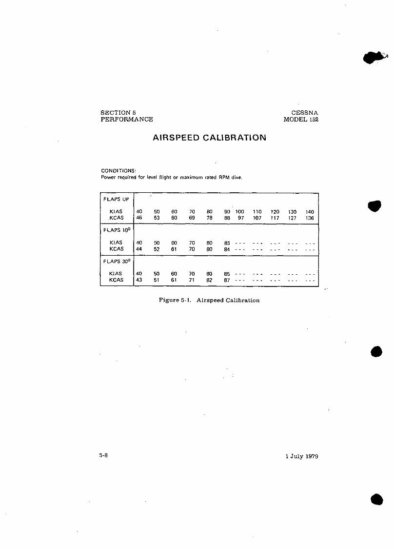
SECTION 5 PERFORMANCE
AIRSPEED CALIBRATION
CONOITIONS: Power required for level flight or maximum rated RPM dive
CESSNA MODEL 152
( FLAPS UP 1 KIAS 40 50 60 70 80 90 100 110 120 130 I KCAS I 46 53 60 69 78 88 97 107 117 127 136 140 1
1 FLAPS 10' 1 KIAS KCAS
FLAPS 30'
Figure 5-1. Airspeed Calibration
40 50 60 70 80 85 - - - - - - - - - - - - - - - 44 52 61 70 80 84 - - - - - - - - - - - - - - -
KlAS KCAS
1 July 1979
40 M 60 70 80 8 5 - - - - - - - - - - - - - - - 43 51 61 71 82 8 7 - - - - - - - - - - - - - - -

CESSNA MODEL 152
SECTION 5 PERFORMANCE
TEMPERATURE CONVERSION CHART
-40 -20 0 20 40 60
DEGREES -CELSIUS
Figure 5-2. Temperature Conversion Chart
1 July 1979

SECTION 5 PERFORMANCE
CESSNA MODEL 152
STALL SPEEDS
CONDITIONS: Power Off
NOTES: 1. Altitude Ion during a stall recovery may be as much a 1 W feet. 2. KlAS valuer are approximate and are bared on airspeed calibration data with power off.
MOST REARWARD CENTER OF GRAVITY
MOST FORWARD CENTER OF GRAVITY
I I I ANGLE OF BANK I
Figure 5-3. Sta l l Speeds
WEIGHT LBS
1670
A
1 July 1979
FLAP DEFLECTION
UP
1 0°
30°
0°
KlAS
40
40
35
KCAS
48
46
43
30°
KlAS
43
43
38
KCAS
52
49
46
45O
KlAS
48
48
42
60°
KCAS
57
55
51
KlAS
57
57
49
KCAS
68
65
81

E CONDITIONS:
,Flaps lo0 a Full Throttle Prior to Brake Release
t Paved, Level. Dry Runway ' Zero Wind %
TAKEOFF DISTANCE
1 SHORT FIELD 1
NOTES: 1. Short field techniwe as soecified in Section 4 2. Prior to takeoff from fields above 3000 feet elevation, the mixture shwld be leaned to give maximum RPM in a full throttle.
static runuo. ~~~ ~
3. Decrease dktancer 10% for each 9 knots headwind. For operation with tailwinds up to 10 knots, increase distances by 10% for each 2 knots. 3. . ~ v . .
Figure 5-4. Takeoff Distance 0 Z M w
-- . . ...~ ~. ..
WEIGHT LBS
1670 -
TAKEOFF SPEED
K ~ A ~ PRESS
A LT FT
S L. - 1000 '2000
3000 4000 5000 6OW1145
8WO
LIFT OFF
50 \ .
A T - 50FT
54
O°C
GRND ROLL
640 ~ ~ 7 0 . 5
775 855 940
1040
70001270 1405
TOTAL TO CLEAR 50 FT OBS
1190 1310 1445 1600 1775 1970 22W 2470 28M
1 O°C
GRND ROLL
695 765 840 925
1020 1125 1245 1375 1525
TOTAL TO CLEAR 50 FT OBS
1290 1420 1565 1730 1920 2140 2395 2705 3080
20°c
GRND ROLL
755 825 910
1000 1lW 1215 1345 1490 1655
TOTAL TO CLEAR 50 FT OBS
1390 1530 1690 1870 2080 2320 2610 2960 3395
30°C
GRND ROLL
810 890 980
I080 1190 1315 1455 1615 1795
40°C
TOTAL TO CLEAR 50 FT OBS
1495 1645 1829 2020 2250 2525 2855 3255 3765
GRND ROLL
875 960
1055 1165 1285 1420 1570 1745 1940
TOTAL TO CLEAR 50 FT OBS
1605 1770 1960 2185 2440 2750 3125 3590 4195
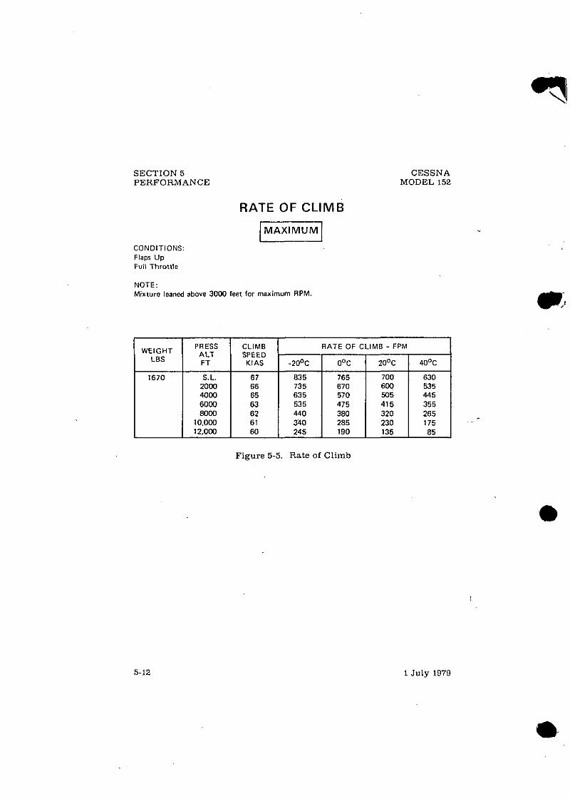
SECTION 5 PERFORMANCE
RATE OF CLIMB
CESSNA MODEL 152
CONDITIONS: Flaps Up Full Throttle
NOTE: Mixture leaned above 3000 feet for maximum RPM.
WEIGHT LBS
Figure 5-5. Rate of Cl imb
1 July 1979
PRESS A LT FT
630 535
1670
CLIMB SPEED KlAS
67 66
S.L. 2000
RATE OF CLIMB - FPM
-20°C I O°C I 20°C I 40°C
83 5 735
765 670
700 600

CIVIL AVIATION AUTHORITY ADDITIONAL LIMITATIONS AND INFORMATION FOR
UNITED KINGDOM CERTIFICATION
CAA Change Sheet 101 Issue 2 to Ulc Cessna 152 and RcIn~slCersns 152 Series Pilots Operating Handbooks/Flighl Manuals lisled below. CESSNA Condmclor's Rcgislralion 152 Serial No. Mark
1l1e limitalions and inlorn~nlion contained hereil~ either suppleme~~l or, i n the ci~sc of conflict, override those in the Pilot's Operaling IlandbooWf:light Mu11ui11. PERFORMANCE To allow for the ~erfonnance detern~incd for U~is series of sc ro~~lu~es . Ule fullowine - adjuslments must be mode to the pcrlonnmce schcdulcd i n thc Pilots Operating HandbooWlighl Mnnual.
1. Increase the Lake-olfdislance by 5% 2. Decrease the scheduled rale ofclimb by 60 Nmin. Note lhnt this
will alfecl the time, fuel and distance to dinlb (to altitude) data. This adjustmen1 becomes eKcctive from U I ~ dale of approval of this Change Shcel and is lo be applied in nddition lo any other ndjuslmc~~t of perli~nnance spcciiicd in h e Pilots Operaling HandbooWlipht Manual. - - APPLICABILITY This Change Sheet is eppli~?bic to lllc liollownng I'ilots Opcrali~~g Ili111dhookrJ1:ligl1t Mlmonls: Aircrafl Twe Model 152 Model 152 Model 152 Model 152 Model 152 Model 152 Model 152 Model 152 Reims Cessne F152 Reims Cessna FI 52 Reims Cessna Fl52 Reims Cessna F152
Aircrefl 'Twe Acrobat A 152 Acrobal A1 52 Acrobat AlS2 Acrobat A IS2 Acrobat A I52 Aerobal A152 Aerobal A1 52
Reim Cessna FA1 52 Rein~s Cessna FA1 52 Reims Cessna FA1 52 Reims Cessna FA I52
To be inserled 111 Seclion 5 of l11e Pilols Operaling Ha~rdbooUFlighl A~a~~~rnlfuci~rg i l~e pages derailing /Ire Itale afCIin~b and Take-O~Disrances asfollow: Manuals marked Pages 5-4, 5-11. 5-12and5-13 Ma~ruals marked " Pages 5-4. 5-12. 5-13 and 5-14 Mamials marked '** Pages 5-4, 5-5. 5-6. 5-7 and 5-8 The CA.4 revisions record sheel is lo be anrended accordingly.
@ CAA Change Sheet 101 CAA Approved lssuc 2 Pugc 1 or I 6 March 1995

C l V l AVIATION AUTHORITY ADDITIONAL LIMITATIONS AND INFORMATION FOR
UNITED KINGDOM CERTWCATION CAA Change Shes1 101 l s u c 1 lo lhc Cusna 152 and RcimYCesrna 152 Scricr POHsl Flight Manu:tlr 2s lirlcd below. CESSNA 152
Consuunar's Serial No.
Rcgilr.lion Mark
The linlilalions and inlomalion canlained hcrcin cilhcr supplcmenl or, in 1hc care olurnnict, orcrridc l lmc in lhc aircrall flight manual.
PEIWORMANCE To allow lor the pcrfomnnce delcrmind lor lhir arics ofacraplancr. lhc lollowing ndjuslmcnls imtsl bc i ~ r i e lo lhc perfornxmce rcllcdulcd in Lhc PilolZ Opcraling HandbmWFlighl Manual.
I. Incrcarc the L~kc+Ndirtanee by 5%. 2. Decrease the scheduled rr leof climb by 10 Nmin. Nolc Iha! this will allcch t l~c lmr . filr.l.
alld distance lo climb (lo allitudc) data.
APPLICABILITY This Change Sheel is applicablc to lltc iollowing Piloa Operaling Handbmkr/Flighl Manualr:
NCTYPE Modcl IS2 Manual Rclcrcncc Dl IO7-2-I3.RPC AIC TYPE Modd 152 Manual Relcrcncs Dl 136-13-RPC AlCTYPE Model IS2 Manual Rdcrcncc D 1170-I-13PH N C TYPE Model I52 Manual Relsrcnce D1190-1-13PH N C TYPE Model 152 Manual Reference DIZIO-1-13PH AICTYPE Model 152 Manual Rclcrencc D1229-13PH NCTYPE Modcl I52 Manual RcRrence D1249-13PH AlC TYPE Model 152 Manual Rclsrsnce D1270-13PH AICTYPE Acrobat A152 Manual Rckrencc Dl 108.2-Il-RPC NCTYPE Aerobal A152 Manual Rclerencc D l 137-13PH MC W E Aerobal A153 Manual Relcrencc D1171-13RPC N C TYPE Acrobat A I D Manual Rclrrence D1191-1-13PH AIC TYPE Aerobal A152 ManualRderence D1211-I-13PH N C TYF'E Aembal A152 Manual Relersnce D1230-13PH-RPC N C TYPE Acrobal A152 Manual Rcferencc DI27I-I3PH-RPC AIC TYPE Rcims Ccrsna Fl52 Manual Rclcrcncc Dl 107-IZGR NCTYPE Rcimr Ccsrna FI52 Manual Rercrencc D1116-13GB AICTYPE Rcims C m n a F152 Manual Rcferencc Dl 170-IICB AiCTYPE Rcims Cessna F152 Manual Rclcrencc D1190-13GB MCTYPE R c ~ C a m FA152 Manual Rclcrcnce Dl 108.13GM &C TYPE R c m Cesma FA152 Manual Rcfrrcncc DII37-IIGB N C TYPE Rclml Ccrrna FA152 Manual Rcfcrcnce DI171~IIGB NCTYF'E RFimr Ccssna FA152 Manual Rcfcrcnse D1191-13GB
Ib be i r m r d in Section 5 of the WH/Flighl Manu01 facing thepu#cs daailiny :he Hutc of Cli,oh m d lirkc-oJjfl>iaoncr~ (11 foI111m:
Alonuds mmkd .- P e g s 5-4.5-11.5-12. and 5-13 f k d - Po#e.sS-4, 5-12 5-13, and S-I4 Alanrdsoturk~d --'- Pq+ S-4.5-5, s-6, 5-7, w d 5 - 8
I l r U.1 ro,i.vinnr rrcordsircn k r o 6s ammdrdwcording(y. a
CAA Chiulpc Sheel 101 lrsuc I

CIVIL AVIATION AUTHORITY ,&DDITIONAL LIMITATIONS AND INFORMATION FOR
UNITED KINGDOM CERTIFICATION
CAA Change Sheet I01 Issue 2 lo Ule Cessna 152 and R e I n ~ s l C e s ~ ~ ~ u 152 Series Pilots Operating HandbokslFlighl Manuals listed brlow. CESSNA C O ~ S ~ N C ~ O ~ Rcgislralion 152 Serial No. Mark
Ule limilalions and infornmlion conlnined herein either supplcrnc~~l or, in the c a e of conflict, override those in the Pilot's Operaling Ila11dbooW1:lighL MUIIU;II. PERFORMANCE To allow for the perfonuance delern~incd fur U~is serics of ;~eropl;lncs, Lhe fullowil~g adjustmenls must be made lo the perfonnmce schcdulcd in lhc Pilols Opcreling HandboWlight Manual.
I. Increase the lake-olTdisldnce by 5% 2. Decrease the scheduled rule of climb by 60 IVmin. Note that lhis
will alTec1 the time, fuel nnd disla~~ce lo climb (lo nltilude) data. This adjustment becomes elTeclive from Ule dale ofi~pproval of ll~is Chi~nge Shcel and is lo be applied in addition lo nny other ndjusl~ncnl of pcrfi)nounce spccilied in llx Pilots Operating HnndbookFlighl Mam~al. APPLICABILITY This Change Sheel is opplicablc lo 1l1c rollowing I'ilols Opcrding I l;~~~dbookdl:ligl~l Manuals: Aircrafl Tvue Model 152 Model 152 Model 152 Mode1 I52 Model 152 Model 152 Model 152 Model 152 Reims Cessna Fl52 Reims Cessnn F152 Reims Cessna F152 Reims Cessna F152
Aircrafl 'fvtx Acrobat A 152 Acrobal A152 Acrobul A152 Aerobnl A152 Aerobnl A152 Aerobnl A 152 Aerobol A152
Reims Cessna FA1 52 Reinn Cessna FA1 52 Ileims Cess~~a FA1 52 Reims Ccssna FA I52
To be inserred in Secrion 5 of (he Pilors OpcralL~g H a ~ ~ d l ~ o o ~ F l i g l ~ r Ma~r~ralficitrg 111e pages cleraili~~g the Rare ofClintb and Take-OgDisrunces asfollo~vs: Manuals marked Pages 5-4, 5-11. 5-/.?and 5-13 $ do Marl~als marked '* Pages 5-4, 5-12. 5-13 and 5-14 Manuals marked '* Pages 5-4. 5-5. 5-6, 5-7 and 5-8 The CAA revisions recod sheer is ro be amended accordingly. CAA Change Sheet101
@ CAA Approved
lssuc 2 Pugc 1 of 1 6 March 1995

CIVIL AVIATION AUTHORITY ADDITIONAL LIMITATIONS AND INFORMATION FOR
CAA Change Sheel 101 Issue 2 lo Uie Cessna 152 and Relnis/Cersnu 152 Series Pilots Operating HandbooksJFlighl Maneals listed below. CESSNA Conslmclol's Rcgistralion 152 Serial No. Mark
l11e limitations and infornialioo conlni~~ed hereill either supp lc~~~e~i l or, in the cilse of conflict. override lhose in h e Pilol's Operating Ha11dbooW1:liglil Muni~ul. - PERFORMANCE To allow lor lhe perlonnmce determined for U~is series of i~eroplwies, the following adjuslmenls must be made to lhe performance scl~cdulcd in the Pilots Operating HandbookIFlighl Monual.
I. Increase the lake-olTdislance by 5% 2. Decrease lhe scheduled rate or climb by 60 R/min. Nole tI1o1 this
will alTect ihe time, fuel arid dislance to climb (lo altibdc) dnla. l h i s adjuslmenl becomes erective from Ule dale of i~pprovel of lhis Clmge Sheet and is lo be applied ia addition to any otlicr ndjuslment of prfonnance specified in the Pilots O~eratine. HandbaoklFli&l Manual. - - APPLICABILITY This Change Sheet is nl)plic;~blc lo ihc followiag I'ilols Opcmli~~g I li~~idhrnks/l:ligl~l Munlmls: Aircrall Twe Model 152 Model 152 Model 152 Model 152 Model 152 Model 152 Model 152 Model 152 Reims Cessna FIS2 Reims Cessnn F152 Reims Cessnn F152 Reims Cessna Fl 52
Aircron 'I'vile Aerobal A 152 Aerobal A152 Acrobnl A152 Aerobal A152 Aerobnt A152 Aerobnl A152 Aerobnl A152
Reieu Cessna FA1 52 Reinis Cessna FA 152 lleims Cessns FA1 52 Reiins Cessna FA1 52
To be inserted in Seerion 5 of d ~ e Pilafs Operoli~~g Ha11d6ook/~ligl1l A4a111rol/uci11g fl~e pages derailing rl~e llare of Climb or~d Take-OflDislunces as/ollo~vs: Manuals marked Pages 5-4. 5-11, 5-12aod5--13 Manuols marked '* Pages 5-4, 5-12.5-13 a11d5-14 Mnnuals n~arked "* Poges 5-4, 5-5. 5-6, 5-7 and 5-8 The CM revisions record sheer is lo be amended accordingly.
@ CAA Change Sheet 101 CAA Approved Isrue 2 Pugc 1 of I 6 March 1995

CIVIL AVIATION AUTHORITY ADDITIONAL LIMITATIONS AND LNFORMATION FOR
UNITED KINGDOM CERTIFICATION
CAA Change Sheet 101 Issue 2 Lo Ule Cessna 152 and Reln~s/Cess~~u 152 Series pilots Operating HandbooksIFlighl Manuals listed below. CESSNA Cor~slruclor's Rcgislralion 152 Serial No. Mark
111e limitations and inforn~alion conlnined herein eill~cr supplcme~~l or, i n the cilse of conflict, override those in the Pilot's Operating lla~~dbooldl:ligl~t MUIIIIB~. PERFORMANCE To allow for lhe perfonnonce delcrnlincd for U~is series of ;~croplu~es. Ule followi~~g adjustments must be made lo Lhe pcrfonnuce scl~cdulcd in thc Pilols Operating HandbooklFlighl Manual.
1. lncrease the take-olTdislance by 5% 2. Decrease lhe scheduled rate of climb by 60 IVmin. Nole lhat this
will affecl the lime, fuel and dislance lo climb (lo olliludc) data. lh i s adjuslmenl becomes effective from Ule dale or approval of lhis Change Sheet and is to be applied in nddilion to my oUar ndjustmc~~t of pcrfon~~;~nce specified in h e Pilots Operating HandbookIFlighl Manual. APPLICABILITY This Change Sheet is applicable lo lhc iollown~~g Pilots Opcrali~~g I l;u~dhwkdl:ligl~l Manmmls: Aircran Twe Model 152 Model 152 Model 152 Model 152 Model 152 Model 152 Model 152 Model 152 Reims Cessna FI52 Reims Cessna FI 52 Reims Cessna FI 52 Reims Cessna F152
Aircran ' I 'vw Aerobal A 152 Acrobat A 152 Acrobal A152 Aerobal A1 52 Aerobal A152 Aerobnl A152 Acrobat A152
Reims Cessl~a FA1 52 Reins Cessna FA1 52 Rcims Cessna FA152 Rci~ns Cessna FA1 52
To be inserfed in Secfion 5 of the Pilols Operofhg Ha~~dbooUFlighf A~n~rsaljucitrg rile pages derailing rlte Hare of Climb and Take-OflDistnnces as follo~vs: Manuals marked Pages 5-4, 5-11. 5-12 and 5-13 Manuals marked * * Pages 5-4. 5-12, 5-13 and 5-14 Manuals marked * * * Pages 5-4, 5-5. 5-6, 5-7 and 5-8 The CAA revisions record sheer is lo be amended accordingly.
@ CAA Change Sheet 101 CAA Approved Issue 2 Page 1 of 1 6Mnrrh 1995

C M L AVIATION AUTAORITY ADDITIONAL LIMITATIONS AND INFORMATION FOR
UNITED KlNGDOM CERTIFICATION CAA Changc S h u l 101 lsruc 1 to thc Cessna IS2 and RcimdCerma IS2 Scrier POHd Flighl Manuals 8s l irad below. CESSNA IS2
Regirlraliau Mark
Thc limilalionr and inlamalion conmined llercin cilhcr supplcrnent or, in thc case olcoNlic1, awrride tlmrc in lhe aircrafl flight manual.
I. lncrcnre lhc lake-oNdisUn<c by 5%. 2. DCCICPY the scheduled ra leaf d imb by 60 Wmin. Nols !ha1 this will a k a l l ~ time, lud.
and dirlance Lo climb (to allitudc) data.
This ad ju r ln~cn lbemmcs~cn ive from thedaleofappmval oflhis Cllangc Shccl and is to be npplicd in addilian to any olhcr adjusmcnl olpcrlormancc specified in Lc POHIFlighl Manual.
APPLICABILITY This Chilnp.~ Shccl is appliable lo llx lollowing Pilots Operaling HandbaakdFlighl Manuals:
N C TYPE Mcdci 152 Manual Relcrencc Dl107-2-13-RPC AIC TYPE Mcdd IS2 Manual Rclsrsncc Dl 136-13-RPC AICTYPE Mcdel 152 Manual Rcrerencc D1170.I-13PH N C TYPE Mcdcl 152 Manual ~ c l ~ ~ ~ ~ ~ Dl 190-I-13PH N C TYPE Mcdcl152 Manull Rsfcrcnce D1210-I-IIPII A/C TYPE Mcdei 152 Manual ~ e l c ~ n c c D1229-I3PH N C TYPE Mcdel I52 Manual Rckrcncc D1249-13PH AICTYPE Mcdcll52 Manual Relcrcncc D1270-13PH AIC TYPE Acrabal A152 ~ a n u a l ~clcrcncc D l 108-2.13.RPC N C TYPE Acrobat A152 Manual Relcrcnco D1137-13PH N C TYPE Acrobat A151 Manual Rercrencc D1171-13RPC N C TYPE Acrobat A152 Manual Rclcrencc D1191-1-13PH N C TYPE Acmbal A152 Manual Rcfcrencc D121I-I-13PH NCTYPE Aerabal A152 Manual Relcrcucc D1230-13PH-RPC N C TYPE Acrobat A152 Manual Rclercncc D1271-13PH-RPC AIC TYPE Rcims Ccsrna FIS2 Manual Relcrcnco Dl 107-13GR AICTYPE Rcimt Ccrrna Fl52 Manual Rclcrcncf Dl 136-13GB AICTYPE Reirnr Ccrrna F152 Manual Relercncc Dl 170-13GB AIC TYPE Rcinu Ccrrna F152 Manual Rderencc Dl 190.13GB AIC TYPE Reim Cessna FAIS2 Manual Relcrsncs Dll08-i3GB N C TYPE Rcirnr Cerma FA152 Manual Rcrercncc Dl 137-13CB NCTYPE Rcims Ccrrna FA152 Manual Refcrcncc D1171-13GB AlC TYPE Rcimr Cesrna FA152 Manual Rcferenm DII9I-13GB

C M L AVIATION AUTHORITY ADDITIONAL LIMITATIONS AND INFORMATION FOR
UNITED KINGDOM CERTWICATION CAA Change Shca In1 ISUC 1 10 Lhe Cema 151 and Reimu'Ccnna 151 Serics POHd Flighl Manwls as l i red k l o w CESSNA 151
Conrtruclor's Scrial No.
Regislrrlior Mark
The limilalions and inlamalion conlaincd herein cilhcr supplemen! or, in the case orcanflid, avcrridc lhorc i n thc aircrall flighl manual.
I. lncrearc the lake-alldistance by 5%. 1. Derrenw the ~ h e d u l c d n t e ofclimb by 60 rumin. Nolc thrl this will allccl l h ~ I~IIIE. lttcl.
and dirmce 10 climb (lo altilude) dam.
This adjunmcnl bosomer eUmive from the dale of approval oflhir Changc Shccl and is lo k applcd is addilion lo an). olller adjurlnlenl ofperlorrnansc rpecificd in thc POWFlighl Manual.
APPLICABILITY This Change Shecl is applicable lo lllc following Pilots Opcraling Handbmku'Flight Manuals:
N C TYPE M d c l IS2 Manual Rcfcrcncc AiC TYPE M d c l 152 Manual REfsrsncc AIC TYPE Mcdcl 152 Manual Rcfcrcncc N C TYPE Model 152 Manual Rclsrsnsc NCTYPE M d c l I52 Manual Rclercnce AiC TYPE Model 152 Manual Relcrcncc N C TYPE M d c l 152 Manual Refcrcncc AiCTYPE Mcdcl 152 Manual Rcfercnce N C TYPE Acrobal A152 Manual Rcfcrencc NCTYPE Aerobal A151 Manual Rcfcrcncc N C TYPE Acrabal A151 Manual Relerencc N C TYPE Acrobat A152 Manual Rcfcrcncc NCTYPE Acrobat A152 Manual Reference NCTYPE Acr0balAl52 Manual Refcrcncc N C TYPE Acrobat A152 Manual Rclcrcncc AiCTYPE Reims Ccsrna F l S l Manual Rcfercnce AiCTYPE Rcinlr Ccrrns F I R Manual Rclcrencc AlCTYPE Rcimr Cerrna F152 Manual Relcrcnw AiC TYPE Rcims Ccssna F I 52 Manual Relcrcncc AIC TYPE Rcimr Cssrna PA152 Manual Rclcrcncc N C TYPE Rcimr Ccrrna FA152 Manual Reference NCTYPE Rcimr Ccrrna FAISZ Manual Rclemcc AlCTYPE Reixnr Ccrsna FA152 Manual Rdercncc
Ib be imcrled i n Scclion 5 o/lhe POH/Flghl Monuol/aeiifi lhcpofier l ' u k ~ - c ~ ~ l ~ ~ ~ ~ r ~ c ~ s os/ollo~~:
hlanuak markd - Pngcr 5-4.5-II. 5-Il, and 5 - D hlwzuob marked ..- P q c s S-4 5-12,543, and 5-14 Mannolr marked .*.- Po#- 3-4,545-6.5-7, ond5-8
I l c CA.1 rcvisions recordrhrer L l o be ammdrd accordingly,
CAA Ch;w&c Shcel 101 lrsuc 1 Page I 01 1
i dlailbvg rhe Xulc 01 Cli,rd vurl

CESSN A MODEL 152
SECTION 5 PERFORMANCE
TIME, FUEL, AND DISTANCE TO CLIMB
CONDITIONS: Flaps UP Full Throttle Standard Temperature
NOTES: 1. Add 0.8 of a gallon of fuel for engine start, taxi and takeoff allowance. 2. Mixture leaned above 3052 feet for maximum RPM. 3. lncreare time, fuel and distance by 10% for each 10°C above standard temperature. 4. Distances shown are bared an zero wind.
NEIGHT LBS
'RESSURE lLTlTUOE
FT
S.L.
1052
2000
3000
4000
5000
6000
7000
8WO
9000
1 o . m
11.000
1 2 . m
IATE OF CLIMB
FPM
- rlME MIN - 0
1
3
5
6
8
10
13
15
18
21
25
29
-
--
FROM SEA LEVEL
UEL USEC jALLONS
Figure 5-6. Time. Fuel, and Distance to C l i m b

. S E C T I O N 5 C E S S N A PERFORMANCE M O D E L 152
CRUISE PERFORMANCE
CONDITIONS: 1670 Pounds Recommended Lean Mixture (See Section 4. Cruise)
NOTE: Cruise sped% are shown for an airplane equipped with speed fairings which increase the r~eedr by approximately two knots.
- : BE1 ARC - <T A$ - - - *
97 92 87 81
- - - 102 96 91 86 81
- - - 101 96 90 85 80 . -- 105 1W 95 90 64
105 99 94 89 83
101 99 93 88 82 -
'RESSURE \LTITUOE
FT
2MM
4000
6WO
8000
l0,oOO
12.000
- N EMP - GPH - - - -
5.7 5.1 4.5 4.1 --.
6.1 5.4 4.8 4.4 3.9
- - - 5.8 5.2 4.6 4.2 3.8
- - - 6.2 5.5 5.0 4.5 4.1
5.8 5.3 4.7 4.3 4.0
5.3 5.0 4.6 4.2 3.9 -
- %NO, 'ERA - KTA! - 101 96 91 86 80
103 101 95 90 85 80
105 100 95 89 64 79
107 104 99 94 89 83
103 98 93 88 82
100 97 92 87 81 -
RPM .
2400 2300 2200 2100 MOO
2450 2400 2300 2200 2100 2WO
2500 2400 2300 2200 2100 MOO
2550 2500 2400 2300 2200 2100
2500 24M) 2300 2200 2100
2450 2400 2300 2200 2100
F i g u r e 5-7. C r u i s e P e r f o r m a n c e
2 STA - %
BHP - - -
71 62
'.55 49
- - - 76 67 60 53 48
- - - 72 64 57 51 46
- - - 76 68 61 55 49
72 65 58 53 48
65 62 56 51 47
- : A N ARD - <TAS - 101 95 90 85 79
102 1 w 95 89 84 78
104 99 94 88 83 77
106 103 98 93 87 82
103 97 92 86 81
99 96 9 1 85 79 -
- CMP - GPH -
5.7 5.1 4.6 4.2 3.8
5.7 5.4 4.9 4.4 4.0 3.7
5.7 5.2 4.7 4.3 3.9 3.6
5.7 5.4 4.9 4.5 4.2 3.8
5.2 4.8 4.4 4.0 3.8
4.8 4.6 4.3 4.0 3.7 -
1 July 1 9 7 9 R e v i s i o n 1 - 31 March 1983

CESSNA SECTION 5 MODEL 152 PERFORMANCE
RANGE PROFILE 45 MINUTES RESERVE
24.5 GALLONS USABLE FUEL
CONDITIONS: 1670 Pounds Recommended Lean Mixture far Cruise Standard Temperature Zero Wind
NOTES: 1. This chart a l low for the fuel used for engine start, taxi, takeoff and climb, and the
distance during climb as shown in figure 5-6. 2. Performance ir shown for an airplane equipped with,speed fairings which inc rew
t h e cruise speeds by approximately two knots.
1 2 . m
10.000
8000
6000
4000
2000
S.L. 300 350 400 450 500
RANGE - NAUTICAL MILES
Figure, 5-8. Range Profile (Sheet 1 of 2)
1 Julv t 97s - " Revision 1 - 31 March 1383 5-15

IHlS O A l A APPLICABLE ONLY 10 AIRPUNTS Wl lH LlCOMlNG 0 2 3 5 U C ENG h E FOR 1 R P U I I E S W.IH EhGlNE MOD T.ED 10 0 2 3 5 N l C . REFER 10 DATA IN SECl lONY SUPPLEMENT
SECTION 5 CESSNA PERFORMANCE MODEL 152
RANGE PROFILE 45 MINUTES R E S E R V E
37.5 GALLONS USABLE FUEL
CONDITIONS: 1670 Pounds Recommended Lean Mixture for Cruise Standard Temperature Zero Wind
NOTES: 1. This chart allows for the fuel used for engine start, taxi, takeoff and climb, and the
distance during climb as shown in figure 5-6. 2. Performance is shown for an airplane equipped with speed fairings which increase
the cruise speeds by approximately two knots.
12,000
10.000
; 8000 U1 ". UI 5 6000
t 5 4
4000
2 w o
S.L. 500 550 600 650 750
RANGE - NAUTICAL MILES
Figure 5-8. Range Profile (Sheet 2 of 2)
1 July 1979 Revision 1 - 31 March 1983

ENDURANCE PROFILE 45 MINUTES RESERVE
24.5 GALLONS USABLE FUEL
CONDITIONS: 1670 Pounds Recommended Lean Mixture for Cruise Standard Temperature
NOTE: This chan allow for the fuel used far engine start. taxi, takwff and climb, and the time during climb as shown in figure $6.
12.000
1 o . m
C 8000
UI Y1 U.
"J 6000 0 3 t 5 .r: 4000
2000
S. L. 2 . 3 4 5 6
ENDURANCE - HOURS
Figure 5-9. Endurance Profile (Sheet 1 of 2)
1 July 1979 Revision 1 - 31 March 1983

I THIS D l T A APPLICABLE ONLY TO AIRPLANES WITH LICOMlNG 0-235-UC ENGlNE. FOR AlRPMNES WITH ENGINE MOOWED TO O-235-NIC. REFER TO O A T 1 IN SECTlON 9 SUPPLEMENT.
SECTION 5 CESSNA PERFORMANCE MODEL 152
ENDURANCE PROFILE 45 MINUTES RESERVE
37.5 GALLONS USABLE FUEL
CONDITIONS: 1670 Pounds Recommended Lean Mixture for Cruise Standa~d Temperature
NOTE: Thir chart allova far the fuel used lor engine start, taxi, takeoff and climb, and the time during climb as shown in figure S6.
1 ?.COO
10.OC")
t; 8000 W LL
6000 3 '= 5 4 4000
2000
S.L. 5 6 7 8 9 10
FNDURANCE - HOURS
Figure 5-9. Enduracce Profile (Sheet 2 of 2)
1 July 1979 Revision 1 - 31 March 1983

LANDING DISTANCE
I SHORT FIELD I (0
CONDITIONS: Flaps 30° Power Of f Maximum Braking Paved, Level, Dry Runway Zero Wind . NOTES: 1. Shon field technique as specified in Section 4. 2. Decrease distances 10% far each 9 knots headwind. Far operation with tailwinds up to 10 knots, increare distances by
10% for each 2 knots. 3. For operation on a dry, grass runway, increase distances by 45% of the "ground roll" figure.
IEIGHT LBS
- RESS A LT FT
- S.L.
lODO 2 m 3000 4 m 5002 60W 7000 8000 -
I TOTAL iRND TO CLEAF l O L L 50 F T 0 8 5
0 CLEAR GRND TO CLEAI 0 FT OBS / ROLL 1 50 FT OBI
Figure 5-10. Landing Distance
- RNO O L L - YH) 520 535 560 580 6M) 625 650 675 -
TOTAL 0 CLEAR GRNC 5FTOBS ROLL
TOTAL '0 CLEAF 0 FT 0 8 5

CESSNA MODEL 152
SECTION6 , WEIGHT & BALANCE1
EQUIPMENT LIST
SECTION 6 WEIGHT & BALANCE/
I ! EQUIPMENT LIST
TABLE OF CONTENTS Page
I
Introduction . . . . . . . . . . . . . . . . . . . . . . . . . . 6-3 Airplane Weighing Procedures . . . . . . . . . . . . . . . . . 6-3 Weight And Balance . . . . . . . . . . . . . . . . . . . . . . 6-6 Equipment List . . . . . . . . . . . . . . . . . . . . . . . .6-13
1 July 1979 6-I/@-2 blank)

CESSNA MODEL 152
SECTION 6 WEIGHT & BALANCE1
EQUIPMENT LIST
INTRODUCTION This section describes the procedure for establishing the basic empty
weight and moment of the airplane. Sample forms are provided for reference. Procedures for calculating the weight and moment for various operations are also provided. A comprehensive list of all Cessna equip- ment available for this airplane is included at the back of this section.
It should be noted that specific information r e ~ a r d i n a the weicht, arm. moment and installed equipment list for this airpiane can only befound in the appropriate weight and balance records carried in the airplane.
It is the responsibility of the pilot to ensure that the airplane is loaded properly.
AIRPLANE WEIGHING PROCEDURES 1. Preparation:
a. Inflate tires to recommended operating pressures. b. Remove the fuel tank sump quick-drain fittings and fuel line
drain plug to drain all fuel. c. Remove oil sump drain plug to drain all oil. d. Move sliding seats to the most forward position. e. Raise flaps to the fully retracted position. f. Place all control surfaces in neutral nosition.
2. Leveling: a. Place scales under each wheel (500# minimum capacity for
scales). b. Deflate nose tire andlor lower or raise the nose strut to center
bubble on level (see fieure 6-1). - 3. Weighing:
a. With the airplane level and brakes released. record the weieht shown on eich scale. Deductthe tare, if any,fromeach readiGg.
4. Measuring: a. Obtain measurement A by measuring horizontally (along the
airplane center line) from a line stretched between the main wheel centers to a plumb bob dropped from the firewall.
b. Obtain measurement B bv measurine horizontally and paral- lel to the airplane centeFline. from center of nose-wheei axle. Left side. toa plumb bobdropped from the line between the main wheel centers. Repeat on right side and average the measure- ments.
5 . Using weights from item 3 and measurements from item 4, the airplane weight and C.G. can be determined.
6. Basic Empty Weight may be determined by completing figure 6-1.
1 July 1979 6-3

S E C T I O N 6 W E I G H T & B A L A N C E 1 E Q U I P M E N T L I S T
Datum IFirewall. Front Face1 Sta. 0.0
C E S S N A M O D E L 152
I Nore Wheel I I I N I I
kale Position
Left Wheel
Right Wheel
I I I I
Sum of Net Weiohts IAs Weiahedl I W I i m h t l
Item I Weight ILbr.1 X C.G. Arm (In.) = Moment/'000 (Lbs.-In.) I
Scale Reading Tare
Airplane Weight (From Item 5, page 6-31 1 \I+S 1 2 9 4 . .
No Oil Filter 16 Q u at 7.5 LbrlGal)
With Oil ~ / l t e r (7 Qtr a t 7.5 LbslGal)
Symbol
L
R
~ d d Oil: I I
I Std. Tanks 11.5 Gal at 6 LbslGall
L.R. Tanks 11.5 Gal at 6 LbslGall
Figure 6-1. Sample Airplane Weighing
Net Weight
Add Unusable Fuel: I I I
I -14.7 I
40.0
I .r I 40.0 1 Equipment Changer
1 July 1979
-. ‘r -14.7
Airplane Basic Empty Weight I 118Q I 2 4 . 9 I I I
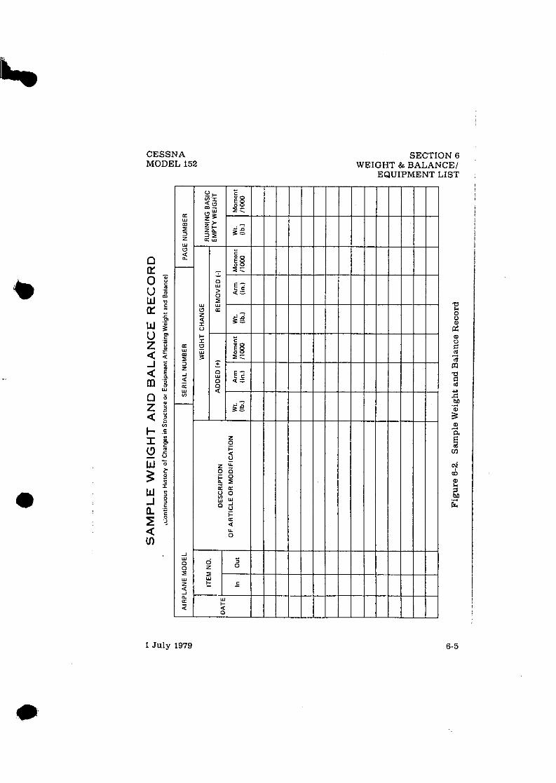
CESSNA MODEL 152
1 July 1979
SECTION 6 WEIGHT & BALANCE1
EQUIPMENT LIST

SECTION 6 WEIGHT & BALANCE1 EQUIPMENT LIST
CESSNA MODEL 152
WEIGHT AND BALANCE The followine information will enable you to operate your Cessna
within the prcsczbed weight and center of gravity 1iinitatio"s. To figure weight and balance, use the Sample Problem, Loading Graph, and Center of Gravity Moment Envelope asfollows:
Take the basic empty weight and moment from appropriate weight and balance records carried in your airplane. and enter them in the column titled YOUR AIRPLANE on the Sample Loading Problem.
NOTE
In addition to the basicempty weight andmoment notedon these records, the C.G. arm (fuselage station) i s also shown, but need not be used on the Sample Loading Problem. The moment which is shown must be divided by 1OOOand this valueused as themomentllOOOon theloading problem.
Use the Loading Graph to determine the moment11000 for each additional item to be carried: then list these on the loading problem.
NOTE
Loading Graph information for the pilot, passengers and baggage is based on seats positioned for average occu- pants and baggage loaded in the center of the baggage areas a s shown on the Loading Arrangements diagram. For loadings which may differ from these, the Sample Loading Problem lists fuselage stations for these items to
. . indica te their forward and aft C.G. range limitation (seat travel and baggage area limitation). Additional moment calculations, based on the actual weight and C.G. arm (fuselage station) of the item being loaded, must be made if the position of the load is different from that shown on the Loadlng Graph.
Total the weiehts and moments/ 1000 and d o t these values on the Center of ~ r a v i t y - ~ o m e n t Envelope to determine whether the point falls within the envelope, and if the loading is acceptable.
1 July 1979

WARWICKSHIRE AVIATION LTD Wellesbourne Airfield, Loxley Lane, Warwickshire CV35 9EU. TellFax: 01789 470225 :a, ;I EASA Approval No: UK.145.01039
.WEIGHT AND CENTRE OF GRAVITY SCHEDULE
Reference WAL 1744
Produced by .. Warwickshire Aviation Ltd.
Nationality and Registration Marks G-BPEO
Constructor .. CESSNA
Aircraft Type .. C152
Maximum Authorised Weight .. 1675 lbs. (Maximum Ramp Weight)
1670 lbs. (Maximum Takeoff Weight)
1670 lbs. (Maximum Landing Weight)
120 lbs. (Maximum weight of baggage
see manual for distribution)
TDTC 3Al9
Forward +31.0 aft of datem at 1350 lbs, or less
With Straight line variation to 32.65" aft of
datum at 1670 lbs.
Aft +36.5" aft of datum at all weight
Refer to C.G. Range and Weight Envelope in P.0.H D l 170-1-13 PH
Reference
Centre of ~ r a v i t ~ Limits ..
Part A. BASIC WEIGHT
,m The basic weight of the aircraft is: 1184.1 lbs. as calculated from the weighing report reference :- Deanland Maintenance 2006105 Dated 29 December 2006 as amended by revisions dated 12 April 201 1 by Warwickshire Aviation due to change of propeller
The centre of gravity of the aircraft in the same condition at this weight and with the landing gear extended is: 34.00 inches aft of the datum.
The total moment about the datum in this condition in lblin. is: 40,259.4
This datum is the one to which the limits in the Certificate of AirworthinesslFlight Manual relate and is defined as fonvard face of the firewall.
The basic weight includes the weight of unusable fuel (9 lbs.! and full oil,
WALIM22 Amendment: 0 08/12/2004

WAL Weight & Centre of Gravity Schedule
Part B. VARIABLE LOAD
The weight and lever arms of the variable load are shown below. The variable load carried depends upon the role in which the aircraft is used :
Pilot (one)
Passenger
Weiqht Ibs. Lever Arm Moment Ib.lin inches
Use actual 39.0" Use actual
Use actual 39.0" Use actual
Part C. LOADING INFORMATION (DISPOSABLE LOAD)
item Weiqht Ibs. Lever Arm Moment Ib./in
Fuel (max 24.5 US Ga11.1147 Ibs.) Use actual +42.0 As calculated
Engine Oil (Included in Basic Weight)
Baggage* (120 lbs max) Use actual As calculated
Passenger Front Seat Use actual 39.0" As calculated
Utility Category Operation - No baggage or rear passengers allowed
Fuel density 6.0 lb US Gal. 7.2 lb Imp Gal
Oil density 7.5 lb.US Gal. 9.0 lb Imp Gal
Note: to obtain the total loaded weight of the aircraft add to the basic weight the weights of the variable and disposable load items to be carried for a particular role
This schedule was prepared on . . . 12 April 201 I ... .... and supersedes all previous issues
Signed ... . . . . .. ... .
on behalf of Warwickshire Aviation Ltd.
a WALIM22 Amendment: 0 08/12/2004

CESSNA MODEL 152
SECTION 6 WEIGHT & BALANCE1
EQUIPMENT LIST
I LOADING ARRANGEMENTS
'pilor or passengn centn at gavity on ad/unsble seats positioned tor average o c c b n t . Numben in parmfhelil indicate forward and an l imi t la f OCWpant center of gravity ranps
..Arm measured to thecenter of the an= hown. NOTES: 1. The usable lucl C.G. arm lor standard tsnkr is located a t nation 42.0: the C.G.
n m for usable fuel in long mnge isnks is nation 39.5.
2. Tha an bagaps wall lapproximate station 941 can be used 8% a convenient interior reference ooinf for drfvmining the location of bawga area fuwlage ifafionl.
STATION STATION IC.G. ARM IC.G. ARM] n
[ X ..w iz 4rR - -AREA 1 13i;:Tu CHILD SEAT
-84 - - AREA 2 "84 - - AREA 2
94- W- STANDARD SEATING OPTIONAL SEATING - Figure 6-3. Loading Arrangements
( BAGGAGE LOADING AND TIE-DOWN
BAGGAGE AREA M A X I M U M ALLOWABLE LOADS
AREA a = 120 POUNDS
AREA @ = 4 0 POUNDS
A R E A S . @ + @ = 1 2 0 POUNDS
TIE-DOWN NET ATTACH POINTS
Figure 6-4. Baggage Loading and Tie-Down
1 July 1979 . 6-7

SECTION 6 WEIGHT & BALANCE/ EQUIPMENT LIST
CABlN HEIGHT MEASUREMENTS *
, L'
t - - 5 6 . ' A 3 8 " 4 5 6 .0
FACE OF INSTRUMENT PANEL REAR WALL OF CABIN
DOOR OPENING DIMENSIONS w;;,H HEIGHT HEIGHT =WIDTH- (TOP) (BOTTOM) (FRONT) (REAR) LWR W I N D O W LINE
31%" 31" + C A B I N FLOOR
C A B I N STATIONS
CABIN WIDTH MEASUREMENTS * D O W N RINGS (6)
%" %"
(C .G . ARMS) 5 6 . 0
Figure 6-5. Internal Cabin Dimensions
1 July 1979

SAMPLE LOADING PROBLEM
1. Basic Empty Weight (Use the data penaining to your airplane as it is presently equipped. Includes unusable fuel and full oil1 . . . . . . . . . . . . . . . . . .
2 . Usable Fuel (A t 6 Lbs.1Gal.J Standard Tanks (24.5 Gal.Maximum) . . . . Long Range T ink r U7.5 Gal. Maximuml . . . Reduced Fuel (As limited by maximum weight1 .
3. Pilot and Passenger (Station 33 to 411 . . . . . .
4. *Baggage - Area 1 (Or passenger on child's seat) (Station 50 ta 76, 120 Lbr. Max.) . . . . . . . .
5. *Baggage -Area 2 (Station 76 to 94, 40 Lbs. Max.) .
S A M P L E A IRPLANE
Weight Ilbs.)
1136
YOUR A IRPLANE
6. RAMP WEIGHT AND MOMENT
7. Fuel allowance for engine start, tax,, and runup . . . . . .
25; Figure 6-8. Sample Loading Problem
Moment IIb. -ins. 11000)
34.0
. Weight
Ilbs.1
Moment lib. - ins.
/ l o w )
1675
- 5 ME^ D X
2 ; S?; 2 5 2
I I I I
56.8
- .2
~ 2 5
8. TAKEOFF WEIGHT AND MOMENT (Subtract Step 7 from Step 61
9. Locate this poipt (1670 at 56.61 on the Center of Gravity Moment Envelope. andsince this point falls wirhin the envelope. the loading is acceptable.
*The maximum allowable combined weight capacity for baggage areas 1 and 2 i s 120 pounds.
1670
'
56.6

Figure 6-7. Loading Graph

LOADED AIRPLANE MOMENT11000 (KILOGRAM-MILLIMETERS)
Figure 6-8. Center of Gravity Mornw- y m a l o p e

AIRPLANE C.G. LOCATION-MILLIMETERS AFT OF DATUM ISTA. 0.01
Figure 6-9. Center of Gravity Limits z
PrJl
ii;

ITEM NO
A l l - i (
2 - 5 4 4 i . 3 - R &I 7 - a
4 2 1 - 4
4 3 3 - H
A 4 1 - K
4 6 1 - 4
4 7 2 - 5 4 7 7 - 4
8 : l -R -1
H Q l - R - ?
EQUIPMENT LIST DESCRIPTION
E V G I N E . L Y C O Y I V G O - Z 3 5 - L 2 C I I U C L , J D E S S T 4 R T E d . C I K D J i ( E T a R . S P A x K P L J Z S AND A L T E H N I I O S B R A C K E T S 1
F I LTE? , . C i d d U R E T O t Z 41R Z L T F d ? l 4 r : l P , 60 A i V , 2 8 V J L T I S E L T W I V E 1 I I L C n O L t R I N S T I L L A T I O V
n I L COOLER (STEWART W4RNERI 7 1 L F I L T F R I N S r 4 L L 4 T I O Y I S P I Y - 3 1 4 E L E ' I E Y T I
d T Y E T CHAUGE P i l i l P E L L i i r I N S T A L L A T I O N
" H 3 P E L L E 9 , * C C A U L E Y F I X E D J I T C ! i L 4 1 3 3 / T C M 6 9 5 8
S P I h J N 6 k I V S T 4 L L 4 T I O N t P 3 3 P E L L t , I S P I % U E R OOME AFT J U L K H E I D I HACK S l D E OF P R 3 P I F H O ~ U L < t l E 4 0 ' I F k ' O S 1 3 E O f P P 3 P l
VACUUH S Y S T E Y , E h l i l N E : N I V E N V4C'J1IY PUUP 3 R V i C U U Y P I I Y P V 4 C J J Y K E L I E F V A L V E
E N ; I N F P R I M I N G S Y S T E Y V A L V F . E N G I N E J I L Q U L C I D R 4 1 V ( Y E T CHAVGE
U H E E L D R A K E L T I R E 4 3 S Y . 6. :XX6 n41N ( 2 1 H H ~ F L 4 S S E H J L Y , f l C C 4 U L E Y ( F A C H I W A K E 4 S S E M 3 L Y . Y C C 4 J L E Y ( L E F T 1 B H M E 4 S S E H S L Y . N C C 4 U L t Y ( R I S Y T I T I M E , & - P L Y B L I C K M P L L I E A C H I T l J d F I E 4 C l i l
A H E E L , J Q l K E d T l A t 4SSY. 6 . 0 3 X b Y A I N ( 2 1 WHEEL 4 S S Y . C L E V E L A Y D 4, l -113 ( E 4 C H I R;14;<E 4SSY. C L E V E L P Y O 3 0 - 7 5 4 I L E F T I 8 9 A A E ASSY, C L E V E L A N D 13-7521 I A I G H T I T I R E , 4 - P L Y B L A C K H A L L l E 4 C H l TLIHE i E 4 C H I
REF DRAWING W T L B S ARM INS =I=
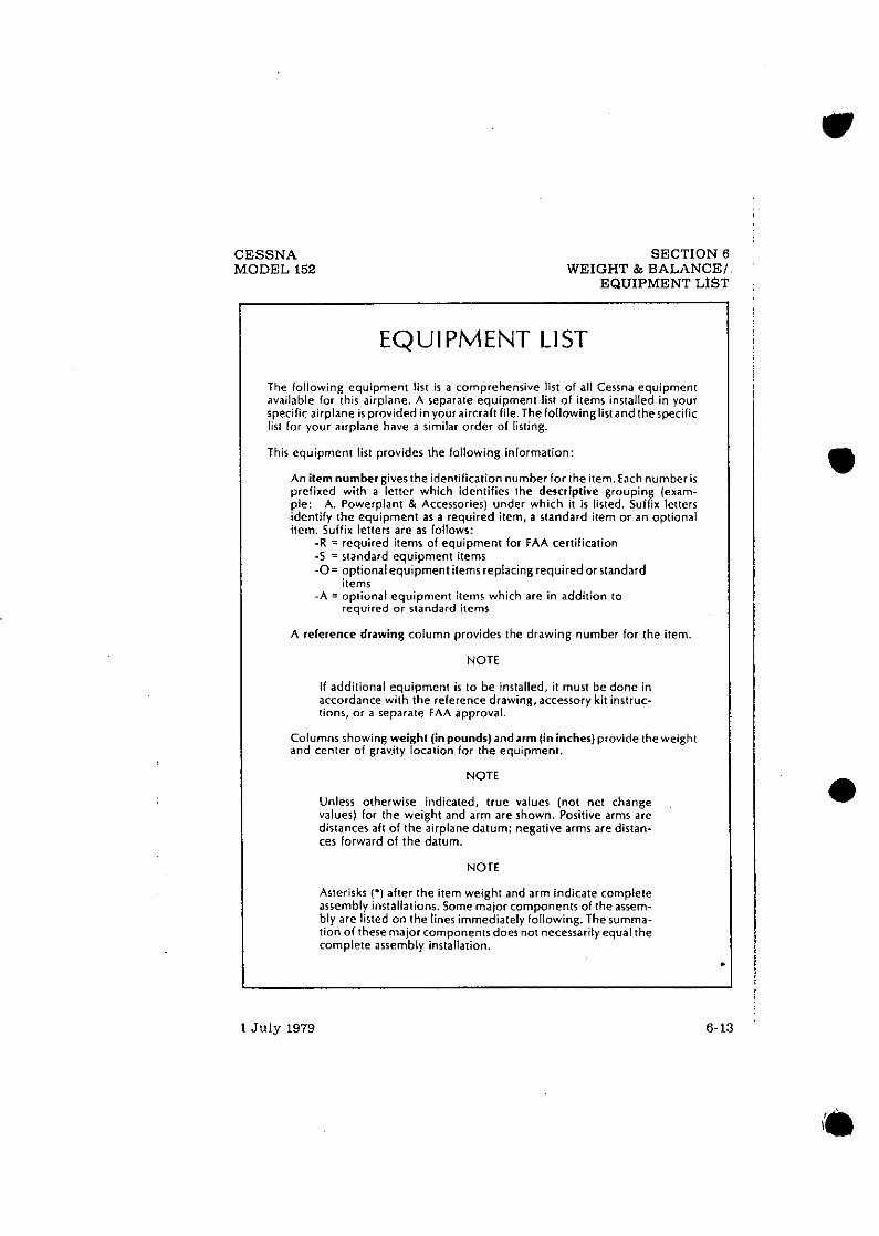
CESSNA MODEL 152
SECTION 8 WEIGHT & BALANCE1
EQUIPMENT LIST
EQUIPMENT LIST
The following equipment l i s t is a comprehensive list of all Cessna equipment available for this airplane. A separate equipment list o f items installed in your s~ecific aimlane is ~ rov ided invour aircraft file.Thefollowinelistandthesoecific l;st for airplane have a similar order of listing.
- This equipment l is t provides the following information:
An itemnumber givesthe identification number for the item. Each number ir prefixed with a letter which identifies the descriptive grouping (exam- ple: A. Powerplant & Accessories) under which it i s listed. Suffix letters identify the equipment as a required item, a standard item or a n optional item. Suffix letters are as follows:
-R = required items of equipment for FAA certification -5 = standard equipment items - 0 = optionalequipment items replacing requiredor standard
items -A = optional equipment items which are in addition to
required or standard items
A reference drawing column provides the drawing number for the item.
NOTE
If additional equipment is to be installed, it must be done in accordance with the reference drawing,accessory kit instruc- tionr, or a separate FAA approval.
Columns rhowing weight (inpoundr) andarm (in incher)provide the weight and center of gravity location for the equipment.
NOTE
Unless otherwise indicated, true values (not net change values) for the weight and arm are shown. Positive arms are distances aft of the airplane datum: negative arms are distan- ces forward of the datum.
NOTE
Aster sks ('I aftw the Itern weight and arm tnajcate complete assembly mstallatrons Some major components o l the assem- bly are llsted on the lwws immedoatel) followmg Thesumma- tion of there major components does not necessarily equal the complete assembly installation
1 July 1979 6-13

-
IIEM NO EQUIPMENT LIST DESCRIPTION I
8 0 4 - R - I U H F E L & T I R E ASSY, 5.03X5 NOSE U H E E L ASSY, MCCAULEY r i a € , 4 PLY B L A C K ~ A L L T U B E
3 9 4 - R - 2 WHEEL C T I R E ASSY, 5.91X5 N O S E WHEEL ASSY, C L E V E L A Y O 4 0 - 7 7 T I R E , '+-PLY B L A C K d A L L T U B E
d H E E L F A I R I N G S 1 5 E T O F 3 1 N D S E U H E E L F A I I I Y G Y A I N U H E E L F A I R I N G I E A C H I
- 8 a A K E F A I R I N G S I E A C H I
1 . C.' E L E C T R I C A L S Y S T E Y S
?! C 4 9 - A - 1 L n n ~ i h S ~ i b d i i n S i A ~ L a i l U N - - S ~ N G L E B U L B C 4 9 - A - 2 L A Y n l Y G C T A X I L I G H T I Y S T L . D U A L R!JLB
0 . I N S T R U M E N T S
1 C l - R I N D I C A T O R t A I R S P E E D
REF DRAWING W T LBS ARM INS

ITEM NO EQUIPMENT LIST DESCRIPTION
I N D I C A T O R . T R U E A l K S P E f D 1 0 5 1 3 2 7 0 l 4 L T I M E T F R S E Y S I T I V E A L T I M E T E A : S E N S I T I V E I 2 0 F T Y b R K I N G S I
F E E T AhlO H l L L l R A R S l 4 L T I ' i E T E R , S E N S I T I V E I 5 0 F T . H A R L I V G S I
( F E E T 4 x 3 M l L L l B A H S l E M C 9 O I N G A L T I M E T E H I I V C L U O E S R E L O C P T I O V
OF C O N V $ N T I O N A L A L T I M E T E R I
EN'??i?Eubk<'!EF&F~rE66T~F P h k b E i P ? h ~ ~ A L T I M E T F H I
4 L T I T J O E ENCODER 1 8 L l N 0 1 0 3 E S NOT R E Q U I R E P A h E L 4 0 U N T l N i l
AHYET E X C L 3 C K I N S T A L L A T I O U
CLOCK, E L E C T R I C CLOCK I N S T A L L A T I D N . D l j l T A L REAOOdT
CL:lC<-TI%lER, D I G I T A L
ECONO*Y M I X T U R E I N O L C A T O R I E G T l I N D I C A T O R 1 ' G I METER G Y X n I N S T A L L A T I O Y I R E O U l R E S ITE'i A 6 1 - 4 1
O I i ? E C T I D N A L I N O I C A T O R A T T I T U D E I N D I C A T O R
RECOROEP. E N G I Y E HOUR M E T E R O l l T S l O F A 1 7 TEMPERATJKE I N D I C A T J R T A C H O M E T E R I N S T A L L A T I O N 1 E N G I Y E
R E C J R D I Y G T A C H I N D I C A T O R I N D I C A T C R . T U R N C O O R D I N A T O R 1 2 4 V O L T O N L Y I Y O I C A T % ? I T U R N C J D R D I N A T O R 1 1 3 - 3 0 V J L T l I N O I C ~ T C ~ I V E R T I C A L S P E E D
E. C A B I N A C C O Y Y U O A T I O X S
SEAT, P I L O T I N O I V I O U A L S L I D I N G SEAT , V E R T I C A L L Y A D J U S T A B L E , P I L O T
REF DRAWING WT LBS
5.7 3 . 1 0.7
0 .7
2 .9
2.9
1 .5
0.5 D.4* 0 . 3 . 0 . 4 1 0.3 0.5
8:: 0 . 4 0.7 0.7 6 .3* 2 .5 2.2 0.6 0.1 1.3r 0.6 1.3 1.3 1.0
11.1 1 7 . 1
ARM INS
1 1 . 3 1 1 . 6 1 7 . 6
1 7 . 6
1 7 . 9
1 7 . 0
2.0
18 .0 14.4. 1 8 . 1 14 .4 * 1 8 . 1 2 7 . 0
t !:8 1 a . o
9.0 1 7 . 4 1 3 . 3 * 1 4 . 7 1 5 . 3
5.2 2 2 . 0 12 .5 * 17 .9 17 .2 17 .2 1 8 . 0
4 5 . 2 65.2

I T E M NO EQUIPMENT LIST DESCRIPTION
l D l V I D U A L Z L l U l N G A O J O S T A R L c . C 3 - P I L g T
. _ i , A U X I L I A R Y 3ACK R E S T C U S H 1 3 N ;EAT C U S H 1 3 V ASSEMBLY .T A S S E Y H L Y
P I L O T L A P ~ Z R N E S S ASSY. P I L O T + ~ R N F < < I N E S T I A 1 N S T L . v P I L O T f.
, L > C ' "r L .
I I N T E D . C A B I N [ N E T CHANGE1
1 C H A N G t l . f S T E l l , C A B I N I I N C L U U E S t V S l N E ( " . ~ i i i u s r g Y S T E X 1
I F. P L A C A R D S , W A R N I N G S C Y A N U A L S
V l G d T S T A L L H 4 R N I N G HORN. P N E L I H A T I C I A U D I B L E P I L f l T ' S O P E P A T I N G H 4 1 0 9 3 3 K A N 0 F A 4
A P P 9 n V E 3 4 I H P L A h E F L I G H T Y A N J A L
G. A U X I L I A R Y E Q U I P M E N T
H P I S T I N G R l N i S , A I R C R A F T C A S I N TOP l U l T F A C T n R V I U S T A L L E O I
C n l l R i l S l r ~ h l P K O O F I N C , I N T E R N A L
REF DRAWING WT LBZ
1 1 . 1 11.3 10.5.
1.3 6 . 4 1.9 1.3 1.0 1.3
2 . 1 L .5 0.5 l .C 0.0 0.5 4 .1
N E G L
14.3
N E G L YEGL
N E G L
0.5 D.5
2 .0
4.5
4RM INS
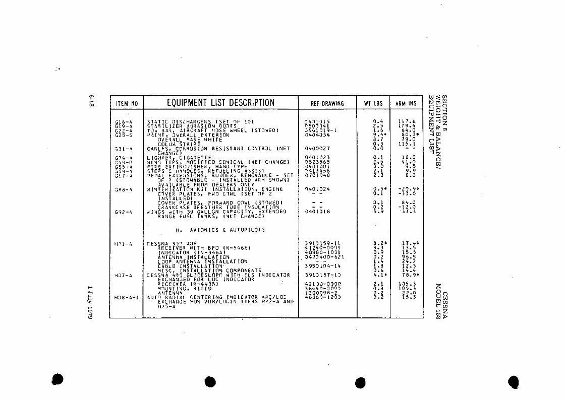
I T E M NO
G l b - 4 G 1 9 - A G 2 2 - 4 G25 -S
.;31-4
G 3 4 - 4 549-11 G 5 5 - 4 $ 5 0 - a is 1 - 4
G R 8 - 4
G 9 2 - 4
H .11 -4
1137-A
H 3 M - 4 - 1
EOUIPMENT LIST DESCRIPTION
S T 4 T I C DIsCHP'RL;ERS I SET q t 1 3 1 S T 4 R I L I Z E R A U R 4 S l O N B O 3 T S T J d 9 4 k r A I R C R A F T N 3 S E " H E E L I S T 3 Y E O l P 4 I V T . S b t R A L L E X T E R I O R
O V E q P L L R A S E W H I T E C U L U H S T R I P E
C I R L F S . , C C K R 0 5 1 0 X R E S I S T A N T C S Y T R J L [ N E T C r tANbE l
L I G F T E 3 . C I G A R E T T E Y IV. T I P S , Y l l 0 1 F I E O C C V I C A L ( Y E T C H 4 N G E I FITE EFTINGJISHEP H ~ N O r Y P t S T E P S H 4 Y D L E S . ~ E F J E L ~ N G A S S I S T 3 E 7 A L E X T E ~ ~ S I O N S , RUIIOE;C. R E M J V A U L E - SET
3F 2 CSTOWABLE - I N S T A L L t D PR,4 S '4ObiYI PV 3 I L I H L E FROM D E A L E R S ONLY
i ! l ' lTEY I Z L T l ? U K I T I N S T 4 L L A T I U N . E Y S I N f C 7 V E R P L A T E S , F H O C l W L I S E T ?IF 2 I N S T A L L E O I C O V E R P L A T E S . F O R ~ A R O c n w L ~STIHEOI C 2 A V U C h S E O t F 4 T H F Z TUBE I U S l J L A T l O N
d I Y G S * I t t i 39 u A L L C N C 4 P A C I T Y , E X T E Y O E 9 R 4 N G E FUEL T4 '4KS . I Y t T C H A Y S E l
H. A V I O N I C S G A U T O P I L O T S
C E S S N A 3 4 3 F R E C E I V E ? H l T H 8F3 I H - 5 4 b E l I N D l C n T O R ( I N - 3 4 6 A 1 A N T i U f J 4 I N S T A L L A T I C N L O O P A N T E h N A I N S T A L L A T I O U C 4 h E L N S T A L L A T l f l Y . Y I SC. I N S T A L L A T I O V COMPONENTS
C E S S Y 4 403 G L l n E S L f l P E N I T H I L S I N D I C A T J K E X C ! i A R J E D FOR L U C I N D I C A T O R R t C E l V E B l U - 4 4 3 8 ) M9U'lT I V G I R I G I D ASTENtJA
4 U T W 4 4 3 I A l C E N T E R I N G I N U I C A T O R A H C I L O : E X C i l A W i E FOR V O R I L O C L N I T E ' I S H ? 2 - A A N 0 1175-4
REF DRAWING WT LBS ARM INS -I-

- LI
E ITEM NO w .. (0 -3
W R - 4 - 2 (0
H L 3 - 4
1 4 1 6 - 4 - 1
H 1 6 - A - 2
117?,-A
H 2 5 - A
4 2 0 - 4 - 1
d 2 R - A - 2
3 3 4 - A
? 1437 -4
+. (D
EQUIPMENT LIST DESCRIPTION
AUT!J R A D I A L C E N T E R I N G 1Y I ) ICAT I IR . A R C l l L S E K C f I A N G E FOR V n R I I L S I Y 2 l C 4 T 3 K I V I T E M H l 7 - A g N L Y
C E S S V A 47, l A R K E R BE4CON R E C L l V E I t I R - 4 0 2 4 , l A N T E N N A * L S H A P E D KJU
C F S S U A 331 TRANSPONDER T K A h I S C E I V E R I R T - 3 5 9 4 1 A N T E U N A
C E S S V A 4'11 TRA,US?ONOER I E X P O K T U S E 1 TH4,dSCE I V t R 1 9 1 - 4 5 9 6 . 1 A N T E N Y A
C E S S Y A 3 ? 1 t d A V I C I Y , 720 C H COW 1 S T U N l T I P E 2 U I R E S H 3 4 - A TO B E O P E R P T I ! l Y 4 L I R E C E I V E R - T R A N S C E I V t R I R T - 3 8 5 1 1 V O R I L O C I N D I C A T O R I I Y - 3 8 5 6 1 Y O U Y T l H I R I N G & Y l S C I T E Y S
CESS '4A 3 C 1 N A V I C O * . 7 2 0 C H COq 2 N 0 U N I T I R E t G J I R E S H 3 7 - A TO B E O P E R A T I D V & L I K 6 C G I V E U - T R A N S C E I V E R I R T - 3 8 5 A 1 V O R I L O C I N O I C A T O R I I N - 3 8 5 A I YOIJYT. h I R I N G & H l S C I T E M S
F 4 t i l G t N C Y LOCATOR TRA! ISH ITTE i ( T S A Y S * I I T E R 1 0 L '4 0 9 E L T - 6 - 1 1 A N T E N N A
E Y E R C E N C Y L n C A T O R T R A N S Y I T T E R ( U S E 0 I N C A N A D A 1 T R A N S ! I I T T E K 19 L *I O M E L T - 6 - 1 C l A N T E Y N A
Y A S l C A V I O ' J I C S K I 1 I U S E O d I T H 1 S T U N l T X : l V I C O * FACTORY I N S T A L L A T I O Y I *SOL il C'JOL I N G Y O I S E F I L T E K I A U D I J I I O N A L T E R N A T 3 R I L H COH 4 N T E N N 4 C A B L E 3 M N I A N T E Y N A C A B L E OY!lI A N T E N N 4 I N S T A L L A T I O N V H F L.H. CON A N T E Y Y A Y I C R O P H O Y E INSTALLATION A U J l O CDNTROL C A ? 1 4 S P E A K F R I N S T L YEA: IPH' )NE I N S T A L L A T I 3 Y
C I W A i i T E N V A & O H N I COUPLEP. K I T l A V A I L A 8 L E
REF DRAWING W I LBS ARM INS

I TEM NO I EOUlPMENT LIST DESCRIPTION
1 5 2 - 1 1 PACKAGE E U U I P M E V T 4 6 1 - A VICUU'i SYSTE ' I F U R > Y R . l S I C 4 3 - A O H Y l F < A S H l U G B E A C 3 V C 4 9 - 4 - 1 L 4 N D I Y b L I G I I T S I N G L E I l J L R 0 6 4 - 4 GYRO I N S T A L L A T I O N 0 8 2 - A O U T S 1 0 E A I R TEYPERATUZE I N 0 0 8 8 - 4 TURN C U O R J I V A T 3 R D J L - 4 H A T E O F C L I Y B 1*O. € 5 5 - A S J N V I S O R S E O 5 - A D U A L CONTROLS 5 3 4 - 6 C I G A R E T T E L I G H T E R HZ;-4 CCSSNA 3 0 5 \IAVICO!i r l l - 3 8 5 1 1 1 1 3 4 - 4 B l S l C A V I O N I C S K I T
1 9 2 1 1 a A V - P A C E G d I P H E N T H l b - 4 - 1 C E S S N 4 3 0 ) T X P N S P O W E R 3 7 - 3 5 : 1 2 5 - 4 R T - 3 8 5 4 2 4 D U N I T H > ~ - A COH ANTEN~IA L COUPLEX KIT
1 5 5 - 4
H 5 b - i
REF DRAWING
0 Y 7N0 U N I T N A V l C O Y FACTURY I N S T L GNLY ' I R H COX A N T E N N A I N S T A L L A T I U W R H C J M ONTFYNA C A B L E O M N I COUPLEA l S I G N 4 L S P L I T T E R 1 G C A H L E
H E 9 O S E T - I I C R U P H O N E , 1 3 5 4 L L ' P U K P O S t CONTROL WHEEL
P A n n E O H E A D P H 3 N E - Y I K E ASSY. ' I E W I X E S A L L - P U R P n S E CONTROL * H E E L
J. S P E C I A L OPT IC IN PACKAGES
0 .4 3 . 4 0 .2 0 .2
1.1
32.1 . 2 . a 1 . 3 1 .o 6 .3 0.1 1.3 9.7 1.0 4.1 0.1 ti. 1 5.3
1:.7* 3.6 8.1 1.0
A E M INS
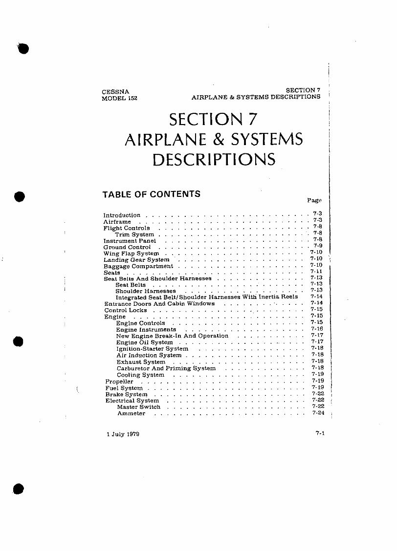
CESSNA MODEL 152
SECTION7 ; AIRPLANE & SYSTEMS DESCRIPTSONS '
SECTION 7 AIRPLANE & SYSTEMS
I
DESCRIPTIONS I
TABLE OF CONTENTS Pagts
. . . . . . . . . . . . . . . . . . . . . . . . . . Introduction 7-3 . . . . . . . . . . . . . . . . . . . . . . . . . . . Airframe 7-3
. . . . . . . . . . . . . . . . . . . . . . . . Flight Controls 7-8
. . . . . . . . . . . . . . . . . . . . . . . . . Trim System 7-8 . . . . . . . . . . . . . . . . . . . . . . . Instrument Panel 7-8
. . . . . . . . . . . . . . . . . . . . . . . . Ground Control 7-9 . . . . . . . . . . . . . . . . . . . . . . Wing Flap System 7-10
. . . . . . . . . . . . . . . . . . . . Landing Gear System 7-10 ';
. . . . . . . . . . . . . . . . . . . . Baggage Compartment 7-10 . . . . . . . . . . . . . . . . . . . . . . . . . . . . Seats 7-11
. . . . . . . . . . . . . . Seat Belts And Shoulder Harnesses 7-13 . . . . . . . . . . . . . . . . . . . . . . . . Seat Belts 7-13
. . . . . . . . . . . . . . . . . . . Shoulder Harnesses 7-13 Integrated Seat BeltlShoulder Harnesses With Inertia Reels 7-14
. . . . . . . . . . . . . . Entrance Doors And Cabin Windows 7-14 . . . . . . . . . . . . . . . . . . . . . . . . Control Locks 7-15
. . . . . . . . . . . . . . . . . . . . . . . . . . . Engine 7-15 . . . . . . . . . . . . . . . . . . . . . Engine Controls 7-15
. . . . . . . . . . . . . . . . . . . Engine Instruments 7-16 New Engine Break-In And Operation . . . . . . . . . . . 7-17
. . . . . . . . . . . . . . . . . . . . Engine Oil System 7-17 . . . . . . . . . . . . . . . . . Ignition-Starter System 7-18
. . . . . . . . . . . . . . . . . . . Air Induction System 7-18 . . . . . . . . . . . . . . . . . . . . . Exhaust System 7-18 ,
. . . . . . . . . . . . . Carburetor And Priming System 7-18 1 . . . . . . . . . . . . . . . . . . . . . Cooling System 7-19 i
. . . . . . . . . . . . . . . . . . . . . . . . . . Propeller 7-19 . . . . . . . . . . . . . . . . . . . . . . . . . . (. Fuel System 7-19 1 . . . . . . . . . . . . . . . . . . . . . . . . Brake System 7-22 ;
. . . . . . . . . . . . . . . . . . . . . . Electrical System 7-22 ;
. . . . . . . . . . . . . . . . . . . . . . Master Switch 7-22 . . . . . . . . . . . . . . . . . . . . . . . . Ammeter 7-24 .

SECTION 7 AIRPLANE & SYSTEMS DESCRIPTIONS
CESSN A MODEL 152
TABLE OF CONTENTS (Continued) Page
Alternator Control Unit And Low-Voltage Warning Light . . 7-24 Circuit Breakers And Fuses . . . . . . . . . . . . . . . . . 7-25
. . . . . . . . . . . . . Ground Service Plug Receptacle 7-25 Lighting Systems . . . . . . . . . . . . . . . . . . . . . . . 7-25
Exterior Lighting . . . . . . . . . . . . . . . . . . . . 7-25 . . . . . . . . . . . . . . . . . . . . . Interior Lighting 7-26
. . . . . . Cabin Heating . Ventilating And Defrosting System 7-27 Pitot-Static System And Ins t run~ents . . . . . . . . . . . . . 7-27
Airspeed Indicator . . . . . . . . . . . . . . . . . . . . 7-29 Vertical Speed Indicator . . . . . . . . . . . . . . . . . 7-29 Altimeter . . . . . . . . . . . . . . . . . . . . . . . . . 7-29
Vacuum System And Instruments . . . . . . . . . . . . . . . 7-29 Attitude Indicator . . . . . . . . . . . . . . . . . . . . . 7-31 Directional Indicator . . . . . . . . . . . . . . . . . . . 7-31 Suction Gage . . . . . . . . . . . . . . . . . . . . . . 7-31
Stall Warning System . . . . . . . . . . . . . . . . . . . . 7-31 Avionics Support Equipment . . . . . . . . . . . . : . . . . 7-32 Audio Control Panel . . . . . . . . . . . . . . . . . . . . . 7-32
Transmit ter Selector Switch . . . . . . . . . . . . . . . 7-32 Audio Selector Switches . . . . . . . . . . . . . . . . . 7-34 Com Auto Audio Selector Switch . . . . . . . . . . . . . 7-34 Com Both Audio Selector Switch . . . . . . . . . . . . . 7-35 Annunciator Lights Brightness And Test Switch . . . . . . 7-35 Sidetone Operation . . . . . . . . . . . . . . . . . . . . 7-35
Microphone-Headset Installations . . . . . . . . . . . . . . . 7-36 Static Dischargers . . . . . . . . . . . . . . . . . . . . . . 7-36
1 July 1979
CESSNA MODEL 152
INTRODUCTION
SECTION 7 AIRPLANE & SYSTEMS DESCRIPTIONS
This section provides description and operation of the airplane andits systems. Some equipment described herein is optional and may not be installed in the airplane. Refer to Section 9. Supplements, for details of other optional systems and equipment.
AIRFRAME The airplane i s an all-metal, two-place, high-wing. single-engine
airplane equipped with tricycle landing gear and designed for general utility purposes.
The construction of the fuselage is a conventions\ formed sheet metal bulkhead. stringer, and skin design referred to a s semimonocoque. Major items of structure are the front and rear carry-through spars to which the wings are attached, a bulkhead and forgings for main landing gear attachment at the baseofthereardoor posts, and a bulkhead with attaching plates a t the base of the forward door posts for the lower attachment of the wing struts. Four engine mount stringers are also attached to the forward door posts and extend forward to the firewall.
The externally braced wings, containing the f ~ e l tanks, are construct- ed of a front and rear spar with formed sheet metal ribs, doublers, and stringers. The entire structure is covered with aluminum skin. The front spars are equipped with wing-to-fuselage and wing-to-strut attach fit- tings. The aft spars are equipped with wing-to-fuselage attach fittings, and are partial-span spars. Conventional hinged ailerons and single-slotted flaps are attached to the trailing edge of the wings. The ailerons are constructed of a forward spar containing balance weights. formed sheet metal ribs and "V" tvDe cor ru~a ted aluminum skin joined tonether at the trailing edge. The flaps are co&tmcted basically thesame asyhe ailerons. with the exception of the balance weights and the addition of aformed sheet - metal leading edge section.
The empennage (tail :tssembly) consists of a conventional vertical stabilizer, rudder, horizontal stabilizer, and elevator. The vertical stabiliz- er consists of a spar, formed sheet metal 5 b s and reinforcements, a wrap- around skin panel, formed leading edge skin and a dorsal. The ~ d d e r is constructed of aformedleading edge skin containinghinge halves. awrap- around skin panel and ribs. and a formhd trailina edge skin with a ground adlustable trim tab at i ts base. The top ,:I the rudderincorporatesaliadlng edge extension which contains a balar ce weight. The horizontal stab~iizer isionstructed of a forward spar, main spar.formed sheet metal ribs and stiffeners, a wrap-around skin panel. and formed leading edge skins. The
1 July 1979 7-3

SECTION 7 AIRPLANE & SYSTEMS DESCRIPTIONS
CESSNA MODEL 152
Figure 7-1. Flight Control and Trim Systems (Sheet 1 of 2)
7-4 1 July 1979

SECTION 7 AIRPLANE & SYSTEMS DESCRIPTIONS
Figure 7-1. Flight Control and Trim Systems (Sheet 2 of 2)
1 July 1979 7-5 i

SECTION 7 AIRPLANE & SYSTEMS DESCRIPTIONS
CESSNA MODEL 152
Figure 7-2. Instrument Panel (Sheet 1 of 2)
7-6 1 July 1979

1. Turn Coordinator 2. Airspeed Indicator 3. Suction Gage 4. Directional Indicator 5. Attitude Indicator 6. Airplane Registration Number 7. Vertical Speed Indicator 8. Altimeter 9. Digital Clock
10. Course peviation and ILS Glide Slope Indicator
11. Transponder 12. ADF Radio 13. Marker Beacon I n d i ~ r t c r Lights
and Switches 14. NavlCom Radio 15. Audio Control Panel 16. Flight Hour Recorder 17. Tachomete; 16. Economy Mixture Indicator (EGT) 19. ADF Bearing Indicator 20. Additional Instrument Space 21. Low-Voltage Warning Light 22. Ammeter
-
23. Map Compartment 24. Cabin Heat Control 25. Cabin Air Control 26. Circuit Breakers 27. Wing Flap Switch and Position
Indicator 28. Mixture Control 29. Throttle (With Friction ~ o c k ) 30. Microphone 31. Elevator Trim Control Wheel
and Position Indicator 2 32. Carburetor Heat Control g 33. Electrical Switches 34. Oil Pressure Gage 35. Oil Temperature Gage 2 36. Cigar Lighter R 37. Instrument Panel and Radio m
Dial Lights Rheostat 4 38. Left and Right Fuel 2
Quantity Indicators 39. Ignition Switch E
CII 40. Master Switch 41. Primer E 42. Parking Brake Control m
Gg Q Q

SECTION 7 AIRPLANE & SYSTEMS DESCRIPTIONS
CESSNA MODEL 152
horizontal stabilizer also contains the elevator trim tab actuator. Con- struction of the elevator consists of a main spar and bellcrank. left and right wrm-around skin panels. and a formed trailing edce skin on the left - half of the elevator: the entire trailing edge of theri&t hglf i s hinged and forms the elevator trim tab. The leading edge of bothleft and right elevator tips incorporate extensions which co;tain balance weights. -
FLIGHT CONTROLS The aifplane's flight control system (see figure 7-1) consists of
conventional aileron. rudder, and elevator control surfaces. The control surfaces are manually operated through mechanical linkage using a control wheel for the ailerons and elevator. and mdderlbrake pedals for the rudder.
Extensions are available for the rudder1 brake pedals. They consistof a rudder pedal face, two spacers and two spring clips. To.instal1 an exten- slon, place the clip on the bottom of the extension under the bottom of the rudder pedal and snap the top clip over the top of.the rudder pedal. Check that the extension is firmly in place. To remove the extensions. reverse the above procedures.
TRIM SYSTEM
A manually-operated elevator trim tab is ~rov ided . Elevatortrimminp is accomplish6d ihrough the elevator trim tab by utilizing the vertically mounted trim control wheel. Forward rotation of the trim wheel will trim nose-down; conversely, aft rotation will trim nose-up.
INSTRUMENT PANEL The Instrument panel (see figure 7-2) 1s designed to place the prlmary
fhght instluments directly in front of the pilot. The gyro-operated fhght instruments are arranrred one above the other. sliehMv to the left of the control column. To the reft of these instruments are the airspeed indicator. turn coordinator, and suction gage. The clock. altimeter. vertical SDeed mdicator. and navigation instrikents are above andlor to the right df the control column. Avionics equipment is stack,:d approximatelv on the centerhne 01 the panel. wltlt space for addlt~onil equipment on tihe lower r~gh t s ~ d c of the lnstrumcnl panel. The rlght s r r e ofthe panelalsocontams the tachometer, ammeter, low-voltage light, economy mixture indicator (EGT) and additional instruments such as ai.light hour recorder. The left switch and control panel. under the primaiy instrument panel, contains
7-8 1 July 1979

CESSNA MODEL 152 AIRPLANE
SECTION ' SYSTEMS DESCRIPTION'
the fuel quanti ty indicators. cigar lighter, and engine instruments pod tioned below the pilot's control wheel. The electrical switches. panel an8 radio light rheostat knob, ignition and master switches, primer, an' parking brake control are located around these instruments. The engin controls. wing flap switch, and cabin air and heat control knobs are to th right of the pilot, a t the center of the switch and control panel. Directl, below these controls are the elevator trim control wheel, trim positiol indicator. microphone, andcircuit breakers. A map compartment ison th extreme right side of the switch and control panel.
For details concerning the instruments, switches, circuit breakers, an1 controls on t h i s panel. refer in this section to the descriptionof the system, to which these items are related.
GROUND CONTROL Effective ground control while taxiing is accomplished through nose
wheel steering by using the rudder pedals: left rudderpedal to steerleft and right rudder pedal to steer right. When a rudder pedal i s depressed. a spring-loaded steering bungee (which is connected lo the nose gear and ta the rudder bars) will.turn the nose wheel through a'& arc of approximately 8.S0 each side of center. By applyingeither left o r ri&ht brake. thedegreeof turn may be incraased up to 30° each side of center.
Figure 7-3. Wing ]Yap Syslem
1 July 1979 7-5

SECTION 7 AIRPLANE & SYSTEMS DESCRIPTIONS
CESSNA MODEL 152
Moving the airplane by handis most easily accomplished by attaching a tow bar to the nose gear strut. If a tow bar is not available. or pushing is required, use the wing struts a s push points. Do not use the vertical or horizontal surfaces to movq the airplane. If the airplane is to be towed by vehicle. never turn the nose wheel more than 30" either side of center or structural damage to the nose gear could result.
The minimum: turning radius of the airplane, using differential braking and nose wheel steering during taxi. i s approximately 24 feet 8 inches. To obtain a minimum radius turn during ground handling. the airplane may b e r o t a t e d a r o u n d e i t h e r m a i n l a n d ~ . ~ ~ ~ e a r by pressingdown on the tailcone just forwardof the vertical stabilizer to raise thenose wheel off the ground.
WING FLAP SYSTEM The wingflapsareof thesingle-slot type withamaximum deflectionof
30' (see figure 7-3). They are extended or retracted by positioningthe wing flap switch lever on the instrument panel to the desired flap deflection uosition. The switch lever i s moved uu or down in a slot in the instrument pnnel that provldes mechanical stopsat the lo0 aid 20° posit~ons For flap settlngs greaterthan 10°,move theswitch levertotherlght toclearthestop and o&icion it as desired. A scale and oointer on the left side of the switch lever indicates flap travel in degrees. The wing flap system circuit is protected by a 15-ampere circuit breaker.labeIedFLAP,on the right sideof the instrument panel.
LANDING GEAR SYSTEM Thelanding gear is of the tricycle type with asteerable nose wheel and
two main wheels. The landing gear may be equipped with wheelfairings. Shock absorption is provided by the tubular spring-steel main landing gear struts and the airloil nose sear shock strut. Each main gear wheel is equipped with a hydraulically actuateddisc-type brakeon thcinboardside of each wheel. When wheel fairings are ins:alled an aerodynamic fairing - covers each brake.
BAGGAGE COMPARTMENT The baggage compartment consists of the area from the back of the
pilot and passenger's seats to the aft cabin bulkhead. Access to the baggage
7-10 1 July 1979
CESSNA MODEL 152
SECTION 7 AIRPLANE & SYSTEMS DESCRIPTIONS
compartment is gained from within the airplanecabin. A baggagenet with six tie-down straps is provided for securing baggage and is attached by tying the straps to tie-down rings provided in the airplane. When loading the airplane. children should not be placed or permitted in the baggage compartment. unless a child's seat is installed, and-any material that might be hazardous to the airplane or occupants should not be placed anywhere in the airplane. For baggage area dimensions, refer to Section 6.
SEATS
The seating arrangement consists of two separate adjustable seats for the pilot and passenger and, if installed, a child's seat in the rear cabin area. The pilot's and passenger's seats are available in two designs: four- way and six-way adjustable.
Four-way seats may be moved forward or aft, and the seat back angle changed. To position either seat. lift the lever under the inboard cornerof the seat. slide the seat into position, release the lever, and check that the seat is locked in place. To adjust the seat back, pull forward on the knob under the center of the seat and apply pressure to the back. To return the seat back to theuprightposition, pull forwardon the sxposedportionofthe seat back frame. Both seat backs will also fold full forward.
The six-way seats may be moved forward or aft, adjusted for height. and the seat back angle changed. Position either seat by lifting the tubular handle under the inboard front comer of the seat bottom and slide the seat to the desired position. Release the lever andcheck that the seat i s locked in place. To raise or lower the seat, rotate the crank located under the outboard comer of each seat. Seat back angle i s at.justable by rotating a lever on the rear inboard comer of each seat. To adjust either seat back. rotate the lever aft and apply pressure .against the back until it stops moving: then release the lever. The seat back may be returned to the upright position by pulling forward on the exposed portion of the lower seat back frame. Check that the release lever has ::etumed to its vertical position. Both seat backs will fold full forward.
A child's seat is available for installation in the rear of the cabin. The ' seat back i s secured to the cabin sidewalls, and the seat bottom is attached to brackets on the floor. This seat i s non-adjustable.
1 July 1979 7-11


SECTION 7 AIRPLANE & SYSTEMS DESCRIPTIONS
CESSNA MODEL 152
S T A N D A R D S H O U L D E R
H A R N E S S
(PILOT'S SEATSHOWN1
SEAT BELT/SHOULDER H A R N E S S WITH INERTIA
R E E L
Figure 7-4. Seat Belts and Shoulder Harnesses
1 July 1979

CESSNA MODEL 152
SECTION 7 AIRPLANE & SYSTEMS DESCRIPTIONS
SEAT BELTS A N D SHOULDER HARNESSES
All seat positions are equipped with seat belts (see figure 7-4). The pilot's and passenger's seats are also equipped with separate shoulder harnesses. Intenrated seat belt/shoulder harnesses with inertia reels can be furnished for the pilot's and passenger's seat positions if desired.
SEAT BELTS
The seat belts used with the oilot's seat. oasseneer's seat, and the child's seat (if installed) are attaEhed to fittings on trhe floorboard. The buckle half of the seat belt is inboard of each seat and has afixed length: the link half of the belt is outboard and is the adjustable part of the belt.
To use the seat belts for the pilot's and passenger's seats, position the seat as desired, and then lengthen the link half of the belt as needed by grasping the sides of the linkand pulling against the belt. Insert and lock the belt llnk into the buckle. Tighten tile belt toasnugfit by pulling the free end of the belt. The seat belt for the child's seat (if lnstalletll 1s used in the same manner a s the belts for the pilot's and passenger's seats. To release the seat belts, grasp the topof the buckle opposite the link and pull upward.
SHOULDER HARNESSES
Each shoulder harness is attached to a r e a r d o o r ~ o s t above the window line and i s stowed behind a stowage sheath above tfie cabin door. To stow the harness, fold i t and d a c e it behind the sheath. No harness is available for the child's seat.
The shoulder harnesses are used by fastening and adjusting the seat belt first. Then, lengthen the harness as required by pulling on the connectine link on the end of the harness and the narrow release strap. Snap the &nnectinglinkfirmly onto theretainingstud on theseatbelt link half. Then adiust to leneth. Removine the hamess is accomolished bv - - pulling upward on the narrow release strap and removing the harness connectinir link from the stud on the seat belt link. In an emereencv. the shoulder harness may be removed by releasing the seat beltf irst and allowing the harness, s t i l l attached to thelinknalf of the seat belt, todrop to the side~of the seat.
Adiustment of the shoulder harness i<imoortant. A orooerlv adiusted , . . . " . harness will permit the occupant to lean forward enough to sit completely erect. but orevent excessive forward movement and contact with obiects during suiden deceleration. Also, the pilot will want the freedom to reach all controls easily.
1 July 1979 7-13

SECTION 7 AIRPLANE & SYSTEMS DESCRIPTIONS
CESSNA MODEL 152
INTEGRATED SEAT BELT/SHOULDER HARNESSES WITH INERTIA REELS
Integrated seat beltlshoulder harnesses with inertia reels are availa- ble for the pilot and front seat passenger.The seat beltlshoulder harnesses extend from inertiareelslocatedin t h e u ~ ~ e r c a b i n s i d e w a l l iust aft ofeach . . cabin door to attach points outboard of the front seats. A separate seat belt half and buckle is located inboard of the seats. Inertiareels allow complete freedom of body movement. However, in the event of asudden deceleration. they will lock automatically to protect the occupants.
To use the seat belt/shoulder harness, position the adjustable metal link on the harness at about shoulder level, pull the link and harness downward. and insert the link in the seat belt buckle. Adjust belt tension across the lap by pulling upward on the shoulder harness. Removal is accomplished by releasing the seat belt buckle, which will allow the inertia reel to pull the harness outboard of the seat.
ENTRANCE DOORS A N D CABIN WINDOWS Entry to, and exit from the airplane is accomplished through either of
two entry doors, one on each side of the cabin (refer to Section 6 for cabin and cabin door dimensions). The doors incorporate arecessedexterior and interior door handle. a key-operated door lock (left door only). adoor stop mechanism, and an openable window.
To open the doors from outside the airplane, utilize the recessed door handle near the aft edge of each door. Grasp the forward edge of the handle and pull out. To close or open the doors from inside the airplane, use the recessed door handle and arm rest. ~ o t h cabin doors should be checked for security prior to flight, and should not be opened intentionally during flight.
NOTE
Accidental opening of a cabin door in fllght due lo improper closing does not constitute a need to land the airplane. The best procedure is to set up the airplane in a trimmed condition at approximately 65 KIAS, momentar- ily shove the door outward slightly, and forcefully close the door.
- Exit from the airplane i s accomplished by grasping the forward edge
of the door handle and pulling. To lock the airplane, lock the right cabin door from the inside by lifting up on the lever near the aft edge of the door. close the left cabin door, and using the ignition key, lock the door.
7- 14 1 July 1979

CESSNA MODEL 152
SECTION 7 AIRPLANE & SYSTEMS DESCRIPTIONS
Both cabin doors are equipped with openable windows. The windows are held in the closed position by a detent equippedlatch on thelower edge of the window frame. To ooen either window. rotate the latch upward. The w~ndows are equipped with a spring-loaded retaining arm which wlll help rotate the window outward. and hold it there. If required. the wlndows may be ooened at anv soeed'un to 149 WAS. All other iabin windows are of the fixeh type and cainot be' opened. Two additional fixed windows may be installed in the cabin top.
CONTROL LOCKS A control lock is provided to lock the aileron and elevator control
surfaces to prevent damage to these systems by wind buffeting while the airplane is parked. The lock consists of a shaped steel rod with a red metal flag attached to it. The flag is labeled CONTROL LOCK. REMOVE BEFORE STARTING ENGINE. To install the control lock. align the hole in the top of the pilot's control wheel shaft with the hole in the top of the shaft collar on the instrument panel and insert the rod into the aligned holes. Installation of the lock will secure the ailerons in a neutral position and the elevators in a slightly trailing edge down position. Proper installation of the lock will place the red flag over the ignition switch. In areas where high or gusty winds occur, a control surface lock should be installed over the vertical stabilizer and rudder. The control lock and any other type of lockingdevice should be removed prior to starting the engine.
ENGINE The airplane is powered by a horizontally-opposed. four-cylinder.
overheail-valve, air-cooled, carbureted engine with a wet sump oil system. The engine is a Lycoming Model 0-235-L2C and is rated at 110 horsepower at 2550 RPM. Major engine accessories (mounted on the front of the engine) include a starter. a belt-driven alternator. and an oil cooler. Dualmaenetos are mounted on an accessory drive pad on the rear of the engine.&ovi- sioris are also made for a vacuum pump and full flow oil filter.
ENGINE CONTROLS
Engine power i s controlled by a throttle located on the lower center portion of the instrument panel. The throttle operates in a conventional manner: in the full forward position, the throttle is open, and in the full aft position, it i s closed. A friction lock, which is a round knurled disk. is located a t the base of the throttle and is operated by rotating the lock clockwise to increase friction or counterclockwise to decrease it.
1 July 1979 7-15

SECTION 7 AIRPLANE & SYSTEMS DESCRIPTIONS
CESSNA MODEL 152
The mixture control, mounted above the right corner of the control pedestal. i s a red knob with raised points around the circumference and is eouiooed with a lock button in the end of the knob. The rich position is full . .. forward. and full aft i s the idle cut-off position. For small adjustments, the control may be moved forward by rotating the knob clockwise. and aft by rotatine the knob counterclockwise. For r a ~ i d or large adjustments, the - - - knob may be movea forward or aft by depressing the lock button in theend of the control, and then positioning the control as desired.
ENGINE INSTRUMENTS
Engine operation is monitored by the foliowing instruments: oil pressure gage. oil temperature gage. and a tachometer. An economy mixture (EGT) indicator is also available.
The oil pressuie gage, located on the left switch and control panel, is operated by oil pressure. A direct pressure oil line from the engine delivers oil at engine operating pressure to the oil pressure gage. Gage markings indicate that minimum idling pressure is 25 PSI (red line), the normal operating range is 60 to 90 PSI (green arc), and maximum pressure is 115 PSI (red line).
Oil temperature i s indicated by a gage located on the lef t switch and control panel. The' gage is operated by an electrical-resistance type .. temperature sensor which receives power from the airplane electrical system. Oil temperature limitations are the normal operating range (green arc) which is 100°F (38OC) to 245°F (1i8°C), and the maximum (red line) which is 245'F (118°C).
The engine-driven mechanical tachometer i s located near the upper center portion of the instrument panel.. The instmment iscalibrated in increments of 100 RPMand indicates both engine and propeller speed. An hour meter below the center of the tachcmeterdial records elapsed engine time in hours and tenths. Instrument markings include anormaloperating range (green arc) of 1900 to 2550 RPM. and a maximum (red line) of 2550 RPM. The upper end of the green arc i s "stepped to indicate approximate ;
RPM for 75% engine power at sea level (2350RPM). at 4000 feat (8450 R.PM), and a t 8000 feet (2550 RPM).'
An economy mixture (EGT) indicator i s available for the airplane and is located on the right side of the instrument panel. A thermocouple probe in the muffler tailpipe measures exhaur~t gas temperature and transmits it to theindicator.The indicator serves asavisual aid to the pilot in adjusting , cruise mixture. Exhaust gas temperature varies with fuel-to-air ratio. power. and RPM. However. the difference between the peak EGT and the EGT a t the cruise mixture setting is essentially constant and this provides a useful leaning aid. The indicator i s equipped with a manually positioned reference pointer.
7- 16 1 July 1979

CESSNA MODEL 152
SECTION 7 AIRPLANE & SYSTEMS DESCRIPTIONS
NEW ENGINE BREAK-IN AND OPERATION
The engine underwent a run-in at the factory and is ready for the full range of use. It is, however, suggested that cruising be accomplished at a minimum of 75% power until ;total of 25 hours has accumulated or oil consumption has stabilized. This w ~ l l ensure proper seating of the rings.
The airplane is delivered from the factory with corrosion preventive oil in the eneine. If. durine the first 25 hours. oil must be added. use onlv aviation gralde straight &era1 oil conforming to Specification No. MIL- L-6082.
ENGINE OIL SYSTEM
Oil for engine lubrication is supplied from a sump on the bottomof the engine. The capacity of the engine sump i s six quarts (one additionalquart is required iI a full flow oil filter is installed). Oil is drawn from the sump through an oil suction strainer screen into the engine-driven oil pump. From the pump, oil is routed directly to the oil cooler and returns to the engine where it passes through the pressure screen, if the engine does not incorporate afull flow oil filter. If the engine is equipped with a full flow oil filter, oil passes from the pump to a thermostatically contmlled bypass valve. If the 011 is cold, the bypass valve all?ws the oil to bypass the oil cooler and flow directly to the filter. If the oil is hot. the bypassvalve routes the oil from the accessory case forward through a flexible hose to the engine oil cooler mounted on the left forward side of the engine.Returning to the accessory case, the oil passes through the filter. The filtered oil then enters a pressure relief valve which regulates engine ,oil pressure by allowing excessive oil to return to the sump. while the balance of the pressure oil is circulated to various engine parts for lubrication. Residual oil returns to the sump by gravity flow.
An oil filler caploil dipstick is located at the rear of the engineon the n e h t side. The filler caoldiostick is accessible throueh an access door in t h i engine ctwling. he engine shoull not be.operacd on less than four auarts of oil. To m~nimizelossof oil through the breather.fill to fivcauans ior lorma1 flights of less than three hours. For extended flight, filito six quarts (dipstick indication only). F , J ~ engine oil grade and specifications. refer to Section 8 of this handbook.
An oil quick-drain valyeis available to replace thedrain plug intheoil sump drain port, and provides r~uicker, cleaner drainine of the e n ~ i n e oil. To drain thd oil with 'this valv; installed, slip a hose over the e& of the valve and push upward on the end of the valve until it snaps into the open position. Spring clips will hold the valve open. After draining, use a suitable tool to snap the valve into the, extended (closed) position and remove the drain hose.
I July 1979 7-17

SECTION 7 AIRPLANE & SYSTEMS DESCRIPTIONS
CESSNA MODEL 152
IGNITION-STARTER SYSTEM
Engine ignition is provided by two engine-driven magnetos, and two spark plugs in each cylinder. The right magneto fires the lower right and the upper left spark plugs, and the left magneto fires the lower left and upper right spark plugs. Normal operation is conducted with both magne- tos due to the more complete burning of the fuel-air mixture with dual ignition.
Ignition and starter operation is controlled by a rotary type switch located on the left switch andcontrol panel. The switch is labeled clock- wise. OFF. R. L. BOTH. and START. The engine should beoperatedon both magnetos (BOTH position) except for magneto checks. The R and L positions are for checking purposes and emergency use only. When the switch is rotated to the spring-loaded START position. (with the master switch in the ON position), the starter contactor i s energized and the starter will crank the engine. When the switchisreleased, itwillautomati- cally return to the BOTH position.
AIR INDUCTION SYSTEM
The eneine air induction svstem receives ram air throueh an intake in - - - - ~~
~~~ ~ " - the lower portion of the engine cowling. The intake i s covered by an air - filter which removes dust and other foreien matter from the induction air. Airflow passing through the filter enters a n airbox. After passingthrough the airbox, induction air enters the inlet in the carburetor which is under the engine, and is then ducted to the engine cy1i:tders through intake manifold tubes. In the event carburetor ice i s encountered or the intake filter becomes'blocked. alternate heated air can be obtained from a shroud around an exhaust riser through a duct to a valve. in the airbox, operated by the carburetor heat control on theinstrumentpane1.Heated airfrom the shroud isobtained from an unfiltered outside source. Use of full carburetor heat a t full throttle will result in a loss of approxin:ately 150 RPM.
. . EXHAUST SYSTEM
.. Exhaust gas from each cylinder passes through riser assemblies to a
muffler and tailpipe on the underside of the engine. The muffler is constructed with a shroud around the outside which forms a heating chamber for carburetorheat and cabin heater air.
CARBURETOR AND PRIMING SYSTEM
Theengine is equipped withanup-draft,float-type, fixed jetcarburetor mounted on the bottom of the engine. The carburetor i s equipped with an enclosed accelerator pump. an idle cut-off mechanism, and a manual mixture control. Fuel is delivered to the carburetor by gravity flow from
7-18 1 July 1979

CESSNA MODEL 152
SECTION 7 AIRPLANE & SYSTEMS DESCRIPTIONS
the fuel system. In the carburetor, fuel is atomized. proportionally mixed with intake air, and delivered to the cylinders through intake manifold tubes. The proportion of atomized fuel to air is controlled, withinlimits, by the mixture control on the instrument panel.
For starting. the engine is equipped with a manual priming system. The primer is actually a small pump which draws fuel from the fuel strainer when the plunger is pulled out, and injects It into the cylinder intake ports when the plunger is pushed back in. The plunger knob, on the instrument panel, is equipped with a lock and. after being pushed full in, must be rotated either left or right until the knob cannot be pulled out.
COOLING SYSTEM
Ram air for engine cooling enters through two intake openings in the front of the eneine cowl in^. The cooline air is directed around the cvlinders and other areas of the e n g n e by baffling, and Is then exhausted th;ough an opening at the bottom aft edge of the cowling. No manual cooling system control is provided.
A winterization kit is available for the airplane. Details ofthis kit are presented in Section 9. Supplements.
PROPELLER The airplahe is equipped with a two-bladed, fixed.pitah, one-piece
forged alummum alloy propeller which is,modized to retard corrosion. The propeller i s 69 inches in diameter.
FUEL SYSTEM The airplane may be equipped with e i thera standard fuel system or
long range system (see figure 7-6). Both systems copsist of twoventedfuel tanks (one in each wing). afuel shutoff valve, fuel strainer, manual primer. and carburetor. Refer to figure 7-5 for fuel quantitydatafor both systems.
f Fuel flows by gravity from the two wing tanks to afuel shutoff valve.
With the valve in the ON position. fuel flows through a strainer to the carburetor. From the carburetor, mixed fuel and air flows to the cylinders through intake manifold tubes. The manual primer draws ittl fuel iron the fuel strainer and injects it into the cylinder intake ports.
Fuel system venting is essential to system operation. Blockage of the venting system will result in a decreasing fuel flow and eventual engine stoppage. Venting is accomplished by an interconnecting line-from the right fuel tank to the left tank. The left tank is'vented overboard through a vent line which is equipped with a check valve. .and protrudes from the

SECTION 7 AIRPLANE & SYSTEMS DESCRIPTIONS
CESSNA MODEL 152
I - FUEL QUANTITY DATA (U. S. GALLONS)
UtL I .'UNUSABLE I FUEL I
Figure 7-5. Fuel Quantity Data
bottom surface of the left wing near the wing strut attach point.The right fuel tank filler cap i s also vented.
Fuel quantity 1s measured by transmitters (one in each tank) and indicated by two electr~cally-operated fuel quanttty indicators on the lower left ort ti on of the instrument uanel. An empty tank is indicated by a red line &d the letter E. When an indicator sl%ws an empty tank, approximately .75 gallon remains in withers standard or long range tank as unusable fuel. The indicators cannot be relied upon for - accurate readings during skids. slips, or unusual attitudes.
The amount of unusable fuel is relatively small due to the dual outlets at each tank. The maximumunusable fuel auantitv. as determined from the most critical flight condition, is about 1.5 gallonitotal. This quantity was not exceeded by any other reasonable flight condition, including pro- longed 30 second full-rudder sideslips in the landing configuration. Takeoffs have not been demonstrated with less than 2gallons total fuel (1 gallon per. tank).
The fuel system is'equipped with drain valves to provide a means for the examination of fuel in the system for contarnination and grade. The svstem shonld be examined before the first flieht of everv dav and after " " &ch refueling, by using the sampler cup provrded to drain fuel from the wine tank sumus. and bv utilizine the fuel strainer drain under an access panel on tberi iht side oithe engine cowling.The fuel tanks should be filled after each flight to prevent condensation.
When the airplane is equipped with long range tanks, it may be I
serviced to a reduced fuel capacity to permit heavier cabin loadings. This is accomplished by filling each tank to the bottom of the indicator on the fuel filler neck. When filled to this level, the tankcontains 13 gallons (12.25 usable in all flight conditions).
7-20 1 July 1979

CESSNA SECTION 7 MODEL 152 AIRPLANE & SYSTEMS DESCRIPTIONS
FUEL OVANTITY INOICATORS
VENT ,WITH
CHECK VALVE1
FUELSHUTOFF
DRAIN CONTROL
PRIMER
CONOITION: SYSTEM SHOWN WITH FUEL SHUTOFF VALVE IN ON POSITION TUROTTLE
.\ CONTROL
CARBURETOR
[ VENT TO ENGINE ' MIXTURE
CONXROL --- MECHANICAL t mr x o b 6 u i a ~ 1 i ~ ~ betwsn furl
ELLCTR1CAL tan,,. fh. I.nkl:Aould be r c ~
CONNECTION moped a h , e8c~!,ef"eli"g $0
.IS".. maxiilum L.P.<I,Y. r - Figure 7-6. Fuel System (Standard and Long Rd.?ge)
1 July 1979 7-21

SECTION 7 AIRPLANE & SYSTEMS DESCRIPTIONS
BRAKE SYSTEM
CESSNA MODEL 152
The airplane has a single-disc, hydraulically-actuated brake on each main landing gear wheel. Each brake i s connected. by ahydraulicline. to a master cylinder attached to each of the pilot's rudder pexals. The brakes are operated by applying pressure to the top of either the left (pilot's) or right (copilot's) set of ~ d d e r pedals. which are interconnected. When the airplane is parked, both main wheel brakes may be set by utilizing the parking brake which is operated by a knob on the lower left side of the instrument panel.
For maximum brakc life, keep the brake system properly malntained. and minimize brake usage during taxi operations and landings.
Some of the symptoms of impending brake failure are: gradual decrease in braking action after brake application, noisy or dragging brakes, soft or spongy pedals, and excessive travel and weak braking action. If any of these symptoms appear, the brake system is in need of immediate attention. If, during taxi or landing roll. braking action de- creases. let up. on the,pedals and then re-apply the brakes with heavy pressure. If the brakes'become spongy or peda: travel increases. pumping the pedals should bui'ld braking pressure. If one brake becomes weak or fails. use the other;'brake sparingly while *using opposite rudder. as required. to offset the good brake.
ELECTRICAL SYSTEM
The airp!ane is equipped with a 28-volt, direct-current electrical system (see figure 7-7). This system uses a 24-volt battery mounted on the right forward side of the firewall as the source of electrical energy and a belt-drivqn 60-amp alternator to maintain the battery's state of charge. Power is supplied to a bus bar, and a master switch controls this power to all circuits, except the engine ignition system, clock, and flight hour recorder (if installed). The flight hour recorder receives power through activation of an oil pressure switch whenever the engine is operating, and '
the clock is supplied with current at all times. All avionics equipment should be turned off prior to starting the engine or using an external power source to prevent harmful transient voltages from damaging the transis- tors in this equipment.
MASTER SWITCH
The master switch is a split-rocker type switch labeled MASTER. and 1s ON in the up position and OFF in the down position. The right half of the switch. labeled BAT, controls all electrical power to the airplane. The left half, labeled ALT, controls the alternator.
7-22 1 July 1979

CESSNA MODEL 152
1 July 1979
SECTION 7
AIRPLANE & SYSTEMS DESCRIPTIONS
Figure 7-7. Electrical System *

SECTION 7 AIRPLANE SYSTEMS DESCRIPTIONS
CESSNA MODEL 152
Sorrnally. both sidcs of the master sw~tch should he used s~mullnr~e- ousiy, however. Iho BAT s ~ d e of the swxrch could be turned ON sepnrntely to check equipment while on the ground. The ALT side of the switch, when placed in the OFF position, removes the alternator from the electrical svstem. With this switch in the OFF uosition. the entire electrical load i s ~" placedon the battery. ~ o n t i n u e d o ~ e r a t i o n with the alternator switchin the OFF ~os i t ion will reduce batterv Dower low enoueh to oDen the batterv contakor, remove power from the alternator field. land alternator restart.
The ammeter, located on the upper right side of the instrument panel. indicates the amount of current, in amperes. from the alternator to the battery or from the battery to the airplane electrical system. When the engine is operating and the master switch is turned on, the ammeter indicates the charging rate applied to the battery. In the event the alternator is not functioning or the electrical loadexceeds theoutput of the alternator. the ammeter indicates the battery discharge rate.
ALTERNATOR CONTROL UNIT AND LOW-VOLTAGE WARNING LIGHT
The airplane is equipped with a combination alternator regulator -- high-low voltage control unit mounted on the engine side of the firewall and a red warninglight.labeledL0W VOLTAGE. under the ammeteron the instrument panel.
In the event an over-voltage condition occurs, the alternator control unit automatically removes alternator field current which shuts down the alternator. The battery will then supply system current as shown by a discharge rate on the ammeter. Under these conditions, depending on electrical system load. thelow-voltage warning light will illuminate when system voltage drops below normal. The alternator cmtrol unit may be reset by turning the master switch off and back on again. If the warning light does not illuminate, normal alternator charging has resumed: however, if the light does illuminate again. a malfunction lri~s uwurred. and the flight should he terminated a s soon as practicable.
NOTE
Illumination of the low-voltage li1,:ht and ammeter dis- charge indications may occur during low RPM conditions with an electrical load on the system, such as during a low RPM taxi. Under these conditions. the light will go out at higher RPM. The master switch need not be recycled since an over-voltage condition has not occurred to de-activate
7-24 1 July 1979

CESSNA MODEL 152
SECTION 7 AIRPLANE & SYSTEMS DESCRIPTIONS
the alternator system.
The warning light may be tested by turning on the landing lights and momentarily turning off the ALT portion of the master switch while leaving the BAT portion turned on.
CIRCUIT BREAKERS AND FUSES '
Most of theelectricalcircuits in theairplane are protected by "push-to- reset" type circuit breakers mounted under the engine controls on the instrument panel. However, alternator output i s protected by a "pull-off" type circuit breaker. The cigar lighter is equipped with a manually-reset type circuit breaker located on the back of the lighter and a fuse behind the instrument panel. The control wheel map light (if installed) is protected by the NAVIDOME circuit breaker, and a fuse behind the instrument panel. Electrical circuits which are not protected by circuit breakers are the battery contactor closing (external power) circuit, clock circuit, and flight hour recorder circuit. These circuits are protected by fuses mounted adjacent to the battery.
A ground service plug receptacle may be installed to permit the use of an external power source for cold weather starting and during lengthy maintenance work on the electrical and electronic equipment. Details of . the ground service p!ug receptacle are presented in Section 9. Supple- ments.
LIGHTING SYSTEMS EXTERIOR LIGHTING
Conventional navigation lights are located on the wing tips and top of the rudder. Additional lighting is available and inc1udes:a single or dual landingltaxi l ight mounted in the cowling nose cap, a flashing beacon located on top of the vertical fin. and a strobe light installed on each wing tip. Details of the strobe light system are presented in Section 9. Supple- ments.
All exterior lights are controlled by rocker switches on the left switch and control panel. The switches are ON in the ur, position and OFF in the down position.
The flashing beacon shotlld not be used when flying through clouds or overcast: the flnshing light reflectedfrom water droplets or particles in the atmosphere, particuiariy at ni,sht, can produce vertigo and loss of orienta- tion.
1 July 1979 7-25

SECTION 7 AIRPLANE & SYSTEMS DESCRIPTIONS
CESSNA MODEL 152
INTERIOR LIGHTING
lnstrumcnt and control panel lighting is provlded b y flood lightino. integral llghtrng. and post lightlng ( ~ f installed). Two concentric rheost.It control knobs on the left swltch and control oanel. labeled PANEL. L I a n d RADIO LT, control intensity of the instrument and control panel lighting. A slide-type switch (if installed) on the overhead console, labeled PANEL LIGHTS. i s used to select flood lighting in the FLOOD position, post lighting in the POST position, or a combination of post and flood lighting in the BOTH position.
Instrument and control panel flood lighting consists of a single red flood light in the forward part of the overhead console. To use the flood lighting, rotate the PANEL LT rheostat control knob clockwise to the desired intensity.
The instrument panel may be equipped with post lights which are mounted at the edee of each instrument and ~ r o v i d e direct liehtine. The lights areoperatedby p l a c t n g t h e ~ ~ ~ ~ ~ ~ ~ ~ ~ ~ ~ s e l e c t o r swlicll. located in the overhead console. in the POST oosltlon andadjustine Ilsht intensllv with the PANEL LT rheostat control knob. Ejy p l a c i n g t h e F % < ~ ~ ~ ~ ~ ~ ~ ~ selector switch in the BOTH position. the post lights can be used in combination with the standard flood lighting.
The eneine instrument cluster (if oost liehtine is installed). radio .- equipmentPand magnetic compass h&;e integral .lighting and operate indeoendentlvof oostorflood 1iehtine.Lieht intensitvof the radio liehtine .. .. is controlled by t i e RADIO LT rt&ostatcontrol knob ?he Integral compass and enrnne instrument cluster kaht lnrensltv i s controlled by the PANEL - LT rheostat control knob.
A cabin dome light. in the overheadconsole. i s operated by a switchon the left switch and control panel. To turn the light on, move the switch to the ON position.
A control wheel map light is available and is mounted on the bottom of the pilot's control wheel. The light illuminates the lower portion of the cabin just forward of the pilot and io holptul when chcclring map3 and othcr flight data during night operations. To operate the light, first turn on the NAV.LT switch: then adjust the map light's intensity with the rheostat control knob located at the bottom of the control wheel.
A doorpost map light is available, and is located on the left forward doorpost. It contains both red and white bulbs and mav be oositioned to " ~~. ~ ~~
illuminate any area desired by thepilot.Thelight is controlled by aswitch. above the light. which islabeledRED.OFF,andWHITE. Placlnethesw!tch in the topp&ition will provide a izdlight. In the bottompositi&. standard
7-26 1 July 1979
CESSNA MODEL 152
SECTION 7 AIRPLANE & SYSTEMS DESCRIPTIONS
white lighting i s provided. In the center position, the map light is turned off. Light intensity of the red light is controlled by the PANEL LT rheostat contrpl knob.
The most probable cause of a light failure is a burned out bulb: however, in the event any of the lighting systems fail to illuminate when turned on. check the appropriate circult breaker. If the circuit breaker has opened (white button popped out), and there is no obvious indication of a short circuit (smoke or odor), turn off thelight switch of the affected lights. reset thebreaker, and turn the switch on again. If the breaker opens again. do not reset it.
CABIN HEATING, VENTILATING AND DEFROSTING SYSTEM
The temperature and volume of airflow into the cabin can be regulated by manipulation of the push-pull CABIN HT and CABIN AIR control knobs (see figure 7-8).
Heated fresh a i r and outside air are blended in acabin manifold just aft of the firewall by adjustment of the heat and air controls: this air i s then vented into the cabin from outlets in the cabin manifoldnear the pilot's and . passenger's feet. Windshield defrost a i r i s also supplied by a duct leading from the manifold to a pair of outlets below the windshield.
For cabin ventilation, pull the CABIN AIR knob out. To raise the air temperature, pull the CABIN HT knob out approximately 114 to 112 inch for a small amount of cabin heat. Additional heat is available by pulling the knob out farther: maximum heat i s available with the C,lrBIN HT knob pulled out nnd the CABIN AIR knob pushod full in. When no heatisdesired in the cabin. the CABIN HT knob is pushed full in. .
., Additional ventilation air may be obtained by opening the adjustable
ventilators near the upper left and right corners of the wir,dshield.
PITOT-STATIC SYSTEM AND INSTRUMENTS
The pi to t -s ta t ic sys tem supp l i es ram a i r pressure t( , the airspeed indicator and stat ic pressure to the airspeed indicator. .,ertical speed indicator and altimeter. The system is composed of either an unheated or heated pitot tube mounted on the lower surface of the left wing, an external static port on the lower left side of the forward fuselage, and the associated plumbing necessary to connect the instruments to the sources.
1 July 1979 7-27

SECTION 7 AIRPLANE & SYSTEMS DESCRIPTIONS
CESSNA MODEL 152
EXHAUST - MUFFLER SHROUD
OEFROSTER- OUTLETS
-ig ADJUSTABLE VENTILATOR
CABINHEAT CONTROL
CODE
0 RAM
WYENTILATINC AIR
t HEATEO AIR
+ BLENOEO AIR
--- MECHANICAL CONNECTION
Figure 7-8. Cabin Heating. Ventilating, and Defrosting System
7-28 1 July 1979

CESSNA MODEL 152
SECTION 7 AIRPLANE & SYSTEMS DESCRIPTIONS
The heated pitot system consists of a heating element in the pitot tube. arocker-typeswitchlabeledPITOTHT on theleft switch andcontrol panel. a 15-amp circuit breaker under the engine controls on the instrument panel, and associated wiring. When the pitot heat switch is turned on. the element in the pitot tube is heated electrically to maintain proper opera- tion in possible icing conditions. Pitot heat should be used only as required.
AIRSPEED INDICATOR
The airspeed indicator is calibrated in knots and miles per hour. Limitation and range markings (in KIAS) include the white arc (35 to 85 knots). green r.rc (40 to 111 knots). yellow arc (ill to 149 knots). and a red line (149 knots).
If a true airspeed indicator is installed. it is equipped with a rotatable ring which works in conjunction with the airspeed indicator dial in a manner similar to the operation of a flight computer. To operate the indicator, first rotate the ring until pressure altitude i s aligned with outside air temperature in degrees Fahrenheit. Pressure altitude should not be confused with indicated altitude. To obtain pressure altitude. momentarily set the barometric scale on the altimeter to 29.92 and read pressure altitude on the altimeter. Be sure to return the altimeter baromet- ;ic scale to the original barometric setting afterpressurealtitude has been obtained. Having set the ring to correct for altitude and temperature, read the true airsoeed shown on the rotatable rinrc bv the indicator oointer. For best accurady, the indicated airspeed shoGdbe corrected to calibrated airspeed by referring to the Airspeed Calibration chart in Section 5. Knowing the calibrated airspeed, read true airspeed on the ring opposite the calibrated airspeed.
VERTICAL SPEED INDICATOR
The vertical speed indicator depicts airplane rate of climb or descent in - feet per minute. The pointer is actuated bv a tmos~her ic pressure chanees - resuiting from changes of altitude a s supplied by the siatic source.
ALTIMETER
Airplane altitude is depicted by a barometric type altimeter. A knob near tho lower left portion of the indicator provides adjustment of the instrunlent's barometric scale to the current altimeter setting.
' f
VACUUM SYSTEM AND INSTRUMENTS An engine-driven vacuum system (See figure 7-9) is available and
1 July 1979 7-29

SECTION 7 AIRPLANE & SYSTEMS DESCRIPTIONS
CESSNA MODEL 152
V A C U U M SYSTEM A I R FILTER
VACUUM RELIEF VALVE I 0 0 )
Figure 7-9. Vacuum Sys tem
I July 1979

CESSNA MODEL 152
SECTION 7 AIRPLANE & SYSTEMS DESCRIPTIONS
provides the suction necessary to operate the attitude indicator and directional indicator. The system consists of a vacuum pump mounted on
' the engine, a vacuum relief valve and vacuum system air filter on the aft , side of the firewall below the instrument panel, and instruments (including a suction gage) on the left side of the instrument panel.
ATTITUDE INDICATOR
An attitude indicator is available and g ivesa visual indication of flight attitude. Bank attitude is presented by a pointer at the top of the indicator relative to the bank scale which has indexmarks at 10°.20". 30°. 60". and90° either side of the center mark. Pitch and roll attitudes are presented by a miniature airplane superimposed over a symbolic horizon area divided into two sections by a white horizon bar.Theupper"biuesky"areaand the lower "ground" area have arbitrary pitch reference linei useful for pitch attitude control. A knob at the bottom of the instrument i s provided for inflight adjustment of the miniature airplane to the horizon bar for a more accurate flight attitude indication.
DIRECTIONAL INDICATOR
A directional indicator i s available and displays airplane heading on a compass card in relation to a fixed simulated airplane image and index. The directional indicator will precess slightly over a period of time. Therefore, the compass card should be set i n accordance with themagnetic compass just prior to takeoff, and occasionally re-adjusted on extended flights. A knob on the lower left edge of the instrument is usedto adjust the compass card to correct for any precession.
SUCTION GAGE
A suctiongage is located on the left s ide of the instrument panel when the airplane is equipped with a vacuum system. Suction available for operation of the attitude indicator and directional indicator is shown by this gage, which i s calibrated in inches of mercury. The desired suction range is 4.5 to 5.4 inches of mercury. A suction reading below this range may indicate a system malfunction or improper adjustment. and in this case, the indicators should not be considered reliable.
STALL WARNING SYSTEM The airplane is equipped with a pneumatic-type stall warning sg stem
consisting of an inlet in the leading edge of the left wing, an air-oper.<ted horn near theupper left corner of the windshield. and associated olumbil n. As the alrplane~approaches a stall. the low pressureon the uppe;surface r:i the wmgs moves forward around the leadmg edge of the wmgs. Thls low

SECTION 7 AIRPLANE & SYSTEMS DESCRIPTIONS
CESSNA MODEL 152
pressure creates a differential pressure in the stall warning system which draws air through the warning horn, resulting in an audible warning at 5 to 10 knots above stall in all flight conditions.
The stall warning system should be checked during the preflight inspection by placing a clean handkerchief over the vent opening and applying suction. A sound from the warning horn will confirm that the system is operative.
AVIONICS SUPPORT EQUIPMENT
I f the airplane is equipped wlth avionics, various avionics support eauipment may also be installed. Equipment available includes two types o i a id lo cont;ol panels, microph&ne:headset installations and control surface static dischargers.The following paragraphs discuss these items. Description and operation of radio equipment is covered in Section 9 of this handbook.
AUDIO CONTROL PANEL Two types of audio control panels (see figure 7-10) are availablefor -.
this airplane, depending upon whether the avionics package includes a marker beacon receiver. The operational features of both audio control panels are similar and are discussed in the following paragraphs.
TRANSMITTER SELECTOR SWITCH
When the avionics,,package includes two transmitters, a two-position toggle-type switch, labeled TRANS SELECT or XMTR (depending upon which audio control panel is installed), is provided to switch the micro- phone to the transmitter the pilot desires to use. The numbers 1 (up position) and 2 (down position) correspond to the first and second (from top to bottom) transmitters, respectively.
The action of selecting a particular transmitter using the transmitter selcctorswitchsiinultaneously selects the audioamplifier associated with that transmitter to provide speaker audlo. For example. if the number one transmitter is selected. the audio amplifier in the number one NAVICOM is also selected and is used for ALL speaker audio. In the event the audio j amplifier in use fails, as evidenced by loss of all speaker audio, selecting the other transmitter will reestablish speaker audio using the other transmitter audio amplifier. Headset audio is not affected by audio amplifier operation.
7-32 1 July 1979

: CESSNA MODEL 152
SECTION 7 AIRPLANE & SYSTEMS DESCRIPTIONS
USED WITHOUT MARKER BEACON
I I TRANS p-- SPEAKER -, SIDETONE I I I NAVjCOM I , , "
SELECT PHONE
L " ~ N s ~ ' ~ ' ~ ' SELECTOR KUDIO SELECTOR SWITCH
\ L A U D 1 0 SELECTOR SPEAKER
SWiTCH SWITCHES SIDETONE VOLUME CONTROL
USED WITH MARKER BEACON
HEADSET SIDETONE SPEAKER SIDETONE INTERNAL ADJUSTMENT
SWITCH
( ' I ' I i ' XMTR ... ... .... ANN LTE
4:. ::lilf I
ill <;I :wi;; i l l l l i : - \ R
TI;ANSMITTER COM AUTO AUDIO SELECTOR A L ANNUNCIATOR SELECTOR AUDIO SELECTOR SWITCHES LIGHTS SWlTCH . SWITCH BRIGHTNESS
AND TEST" SWITCH"-
I Ju ly 1979
F igure 7-10. Audio Control Panel
7-33

SECTION 7 AIRPLANE & SYSTEMS DESCRIPTIONS
AUDIO SELECTOR SWITCHES
CESSNA MODEL 152
Both audio control panels (see figure 7-10) incorporate three-position toggle-type audio selector switches for individual control of the audio from systems installed in the airplane. These switches allow receiver aud io to be d i rec ted to the a i r p l a n e s p e a k e r o r to a headse t , and heard s i n g l y o r in combina t ion w i th o the r rece ivers . To h e a r a pa r t i cu l a r rece iver on the a i r p l a n e s p e a k e r , p l ace t h a t reci3iver's aud io s e l ec to r swi tch i n the u p (SPEAKER) pos i t ion . T o Lister; to a rece iver o v e r t h e headset, place that receiver's audio selector switch in the down (PHONE) position. The center (OFF') position turns off a l l audio from the associated receiver.
NOTE
Volume level i s adjusted us ing the individual receiver volume controls on each radio.
When a marker beacon receiver i s not installed, audio from both NAV and COM frequencies is combined, and is selected by the audio selector switches labeied NAVICOM. 1 and 2. -
A special feature of the audio control panel used with amarker beacon receiver is separate control of NAV and COM audio from the NAVICOM radios. With this installation. the audio selector switches labeled NAV. 1 and 2 select audio from the navigation receivers of the NAVICOM radios onlv. Communication receiver audio i s selected by thc switches labeled COM. AUTO and BOTH. Description and bperatioi of these switches i s described in later paragraphs. I .
COM AUTO AUDIO SELECTOR SWITCH , . .
If the airolane i s eouiooed with a n audio control panel having marker . a.
beacon cont;ols. a three-position toggle switch. labeled COL! ~ U T O . i s provided to automatically match the audio of the appropriate NAVICOM &nmunica t ions receive; to the t ransmit ter selecied bv the t rawmit ter selector switch. When the COM AUTO selector switch i s placed in the up (SPEAKER) position, audio from the communications receiver selected by the transmitter selector switch will be heard o n t h e airplane spetker. Switchina the transmitter selector switch to the other transmitter aUlo- .- m a t ~ c a l l y sw i t ches the o the r c o m m u n ~ c a t i o n s receiver xudlo to th . speaker l ' h ~ s a u t o m a t i c a u d ~ o s w ~ t c h ~ n g featuremay also beutlllzed when
7-34 1 July 1979

CESSNA iMODEL 152
SECTION 7 AIRPLANE & SYSTEMS DESCRIPTIONS
l is tening on a headse t by placing the COM AUTO switch in the down (PHONE) position. If automatic audio selection is not desired. the COM AUTO selector switch should be placed in the center (OFF) position.
COM BOTH AUDIO SELECTOR SWITCH
If the airolane i s eauiooed with an audio control oanel having marker . .. bencon cont;ols. a three-posltlon toggle swltch. labeled COM BOTH. IS prov~ded to allow both COM receivers to be monitored at the same tlrne For examole. i f the COM AUTO s w ~ t c h 1s in the SPEAKER oosltlon. wlth the t r ansmi t t e r se lec to r switch in the number one t ransmit ter position. number one communications receiver audio will be heard on the airplane soeaker. If it i s also desired to monitor the number two communications receiver audio without changing the position of the transmitter selector swi tch , place t h e COM BOTH seleotor switch i n the u p (SPEAKER) position so that the number two communications receiver audio will be heard in addition to the number one communications receiver audio. This feature can also be used when listening on a headset by placing the COM BOTH audio selector switch in the down (PHONE) position.
NOTE
The combination of placing the COM AUTO switch in the SPEAKER posit ion and the COM BOTH switch in the PHONE position (or vice versa) i s not normally recom- mended a s it will cause audio from both communications receivers (and any other navigation receiverwith i ts audio selector switch in the PHONE position) tnbe heard on both the airplane speaker and the headset sir~rultaneously.
ANNUNCIATOR LIGHTS.BRIGHTNESS AND TEST SWITCH
When a marker beacon receiver i s installed. the audio control vanel includes a three-positiontoggle-type switch tocontrol the brightnesslevel of the marker beacon indicator liahts. When the switch is olaced in the center (DAY) position. the indicator lights will show full bright. When this switch is placed in the up (NITE) position, the lights are set to a reduced level for typical night operations and can be further adjusted using the RADIO LT dimming rheostat knob. The down (TEST) position illuminates all lamps (except the ARC light in the NAV indicators) which are controlled.by the swit.:h to the full bright level to verify lamp operation.
SIDETONE OPERATION
Cessna radios are equipped with sidetone capability (monitoring of the ooerator's own voice transmission). While adiustinn sidetoneoneither audio cohtrol panel. be aware that if the sidetone volume level is set too high, audio feedback (squeal) may result when iransmitting.
1 July 1979 7-35

SECTION 7 AIRPLANE & SYSTEMS DESCRIPTIONS
CESSN A MODEL 152
On airplanes not equipped with marker beacon receivers, acontrol for soeaker sidetone volume only is provided on the audio control panel. To ablus t the level of the sldetone heard on the speaker. rotateche knob. labclcd SIDETONE VOL. clockw~se to mcrease volume or counterclock- wise to decreaseit. Sidetone provided through the headset i s notadjustable by the pilot on audio control panels without marker beacon.
On airplanes with marker beacon recelvers, sidetone is provided in both the speaker and headset anytime the COM AUTO selector switch is utilized. Placing the COM AUTO selector switch in.the OFF position will e lmmate s ~ d e t ~ n e . Sidetone lnternal adlustmentsareava~labie to the pilot l h r o u ~ h the front of the audlo control panel (see figure 7-10). Ad~ustment can be made by removing the appro~riateplug-button from the audio control panel (left button for headset adjustment and right button for speaker adjustment), inserting a small screwdriver into the adjustment potentiometer and rotating it clockwise to increase the sidetone volume level.
MICROPHONE-HEADSET INSTALLATIONS Three t v ~ e s of microohone-headset installations are offered. The ".
standard system provided with avionics equipment includes a hand-held microphone and separate headset. The keving switch for this microphone . - is on <he microphone. Two optional microphone-headset installations are also available: these feature a single-uni'. microphone-headset combina- tion which permits the pilot to conduct radio communications without interrupting other control operations to .~andle a hand-held microphone. One microphone-headset combination is offered without a padded headset and the other version has a padded headset. The microphone-headset combinations utilize a remote keying switch located on the left grip of the pilot's control wheel. The microphone an2 headset jacks are locatedon the pedestal below the instrument panel. Audio to all three headsets is controlled bv the individual audio selector switches and adiusted for volume levei by using the selected receivar volume controls. *
NOTE
When transmitting, the pilot should key the microphone. place the microphone as close as possible to the lips and speak directly into it.
STATIC DISCHARGERS If frequent IFR flights are planned, installation of wick-type static
dischargers i s recommended to improve radio communications during flight through dust or various forms of precipitation (rain, snow or ice
7-36 1 July 1979
CESSNA MODEL 152
SECTION 7 AIRPLANE & SYSTEMS DESCRIPTIONS :
crystals). Under these conditions, the build-up and discharge of static electricity f rom the trailing edges of the wings, rudder, elevator, propeller tips. and radio antennas can result in loss of usable radio signals on all communications and navigation radio equipment. Usually the ADF is first to be'affected and VHF communication equipment is the last to be affected.
Installation of static dischargers reduces interference from precipita- tion static. but it is possible to encounter severe precipitation static conditions which might cause the loss of radio signals, even with static dischargers installed. Whenever possible, avoid known severe precipita- tion areas to prevent loss of dependable radio signals. If avoidance is impractical. minimize airspeed and anticipate temporary loss of radio signals while in these areas..
1 July 1979 7-37/(7-38 blank)

CESSNA MODEL 152
SECTION8 :
HANDLING . SERVICE & MAINTENANCE
SECTION 8 AIRPLANE HANDLING. i 1
SERVICE & MAINTENANCE 1 TABLE OF CONTENTS
Page
Introduction . . . . . . . . . . . . . . . . . . . . . . . . . . 8-3 ldentiiication Plate . . . . . . . . . . . . . . . . . . . . . . 8-3 Owner Follow-Up System . . . . . . . . . . . . . . . . . . . 8-3
Publications . . . . . . . . . . . . . . . . . . . . . . . . 8-3 Airplane File . . . . . . . . . . . . . . . . . . . . . . . . . 8-4 Airplane Inspection Periods . . . . . . . . . . . . . . . . . . 8-5
FAA Required Inspect ions . . . . . . . . . . . . . . . . . 8-5 Cessna Progressive Ca re . . . . . . . . . . . . . . . . . . 8-6 Cessna Customer Care Program . . . . . . . . . . . . . . 8-6
Pilot Conducted Preventive Maintenance . . . . . . . . . . . . 8-7 Alterations Or Repairs . . . . . . . . . . . . . . . . . . . . . 8-7 Ground Handl ing . . . . . . . . . . . . . . . . . . . . . . . 8-7
Towing . . . . . . . . . . . . . . . . . . . . . . . . . . 8-7 Park ing . . . . . . . . . . . . . . . . . . . . . . . . . . . 8-8 Tie-Down . . . . . . . . . . . . . . . . . . . . . . . . . 8-8 Jack ing . . . . . . . . . . . . . . . . . . . . . . . . . . 8-8 Leveling . . . . . . . . . . . . . . . . . . . 8-9 Flyable S torage . . . . . . . . . . . . . . . . . . . . . . 8-9 .
Servicing . . . . . . . . . . . . . . . . . . . . . . . . . . 8-10 Engine Oil . . . . . . . . . . . . . . . . . . . . . . . . 8-10 Fuel . . . . . . . . Landing Gea r . . .
Cleaning And Care . . . Windshield-Windows Painted Surfaces . . Propeller Care . . . Engine Care . . . . Interior Care . . . .
1 July 1979 8-ll(8-2 blank)

CESSNA SECTION 8 MODEL 1.52 HANDLING. SERVICE
& MAINTENANCE '
INTRODUCTION This section contains factory-recommended procedures for proper
ground handling and routine care and servicing of your Cessna. It also identifies certain inspection and maintenance requirements which must be followed if your airplane is to retain that new-plane performance and dependability. It i s wise to follow a planned schedule of lubrication and preventive maintenance based on climatic and flying conditions encoun- tered in your locality.
Keep in touch with your Cessna Dealer and take advantage of his knowledge and experience. He knows your airplane and how to maintain it. He will remind you when lubrications and oil changes are necessary. and about other seasonal and periodic services.
IDENTIFICATION PLATE All correspondence regarding your airplane should include the SE-
RIAL NUMBER. The Serial Number. Model Number. Production Certifi- cate Number (PC) and Type Certificate Number (TC) can be found on the Identification Plate, located on the cabin floor below the left rear corner of the pilot's seat. The plate i s accessible by sliding the seat forward and lifting the carpet in this area. Located adjacent to the 1denti.fication Plate is a Finish and Tr im Plate which contains a code describing theinterior color scheme and exterior paint combination of the airplane. The code may be used in conjunction with an applicable Parts Catalog if fmish and trim information is needed.
OWNER FOLLOW-UP SYSTEM
Your Cessna Dealer has an Owner Follow-Up System to notify you when he receives information that applies to your Cessna. In addition, if you wish. YOU may choose to receive similar notification. in the form of service ~ e i t e r s , d&ectly from the Cessna Customer Services Department. A s u b s c r i ~ t i o n form i s suoolied in vour Customer Care Pxo6?ra.m book for your use.should you choose to r e b e s t this service. You]: Cessna Dealer will be glad to supply you with details concerning these follow-up programs, and stands ready. through his Service Department, to supply you with fast. efficient, low-cost service.
PUBLICATIONS
Various publications and flight operation aids are furnished in the

SECTION 8 HANDLING. SERVICE & MAINTENANCE
CESSNA MODEL 152
airplane when delivered from the factory. These items are listed below.
CUSTOMER CARE PROGRAM BOOK PILOT'S OPERATING HANDROOK AND FAA APPROVED AIRPLANE FLIGHT MANUAL AVIONICS OPERATION GUIDE PILOT'S CHECKLISTS POWER COMPUTER CUSTOMER CARE DEALER DIRECTORY
The following additional publications. plus many other supplies that are applicable to your airplane. are available from your Cessna Dealer.
INFORMATION MANUAL (Contains Pilot's Operating Handbook Information) SERVICE MANUALS AND PARTS CATALOGS FOR YOUR:
AIRPLANE ENGINE AND ACCESSORIES AVIONICS
Your Cessna Dealer has a Customer Care Supplies Catalog covering all available,items, many of which he keeps on hand. He will be happy to place an order f o r any item which i s not in stock.
I NOTE
A Pilot's Operating Handbook and FAA Approved Air- plane Flight Manual which i s lost o r destroyed may be replaced, by contacting your Cessna Dealer o r writing directly to the Customer Services Department. Cessna. Aircraft Company. Wichita. Kansas. An affidavit con- taining the owner's name, airplane ser ia l number and registration number must be included in replacement requests since the Pilot's Operating Handbook and FAA Approved ~ i r ~ l a n e ~ l i ~ h t ~ a n u a l isidentified for specific oirplonc3 only.
AIRPLANE FILE
There are nilscellaneous data. lnforrnatron and llcenses that are a part uf the airplane f l le The following is ;L checklist for that flle. In addltlon a periodic check should be made of the latest Federal Aviation Regulations to ensure that a l l data requirements a r e met.
8-4 1 July 1979

CESSNA 'MODEL 152
SECTION 8 HANDLING. SERVICE
& MAINTENANCE
A. To be displayed in the airplane at all times: 1. Aircraft Airworthiness Certificate (FAA Form 8100-2). 2. Aircraft Registration Certificate (FAA Form 8050-3). 3. Aircraft Radio Station License. if transmitterinstalled(FCC Form
556).
B. To be carried in the airplane at all times: 1. Pilot's Operating Handbook and FAA Approved Airplane Flight
Manual. 2. Weight and Balance. and associated papers (latest copy of the
Repair and Alteration Form. FAA Form 337, if applicable). 3. Equipment List.
C. To be made available upon request: 1. Airplane Log Book. 2. Engine Log Book.
Most of the items listed are required by the United States Federal Aviation Regulations. Since the Regulations of other nations may require other documents and data. owners of airplanes not registeredin theunited States should check with their own aviation offici:ds to determine their individual requirements.
Cessna recommends that these items. plus the Pilot's Checklists. Power Computer. Customer Care Program book and Customer Care Card. be carried in theairplane at ail times.
AIRPLANE INSPECTION PERIODS
FAA REQUIRED INSPECTIONS
As required by Federal Aviation Regulations, all civil aircraft of U.S. registry must undergo a complete inspection (annual) each twelvecalend- ar months. In addition to the required ANNUAL inspection, aircraft operated connnercially (for hire) must have a complete inspection every 100 hours of operation.
The FAA mav reouire other insoections bv the issuanceof airworthi- ness directives ~ppli'cable to the aikplane. en>ne. propeller and compo- nents. It i s tne responsibility of the ownerloperator to ensure compliance with all applicable airworthinessdirectives and. when theinspections are repetitive. lo take appropriate steps to prevent inadvertent noncom- pliance.
In lieu of the 100 HOUR and ANliUAL inspection requirements. an airplane m a y be inspected in accordance with a progressive inspection
1 July 1979 8-5

SECTION 8 HANDLING. SERVICE & MAINTENANCE
CESSNA MODEL 152
schedule, which allows the work load to bedividedinto smaller operations that can be accomplished in shorter time periods.
The CESSNA PROGRESSIVE CARE PROGRAM has been developed to provide a modern progressive inspection schedule that satisfies the complete airplane inspection requirements of both the 100 HOUR and ANNUAL inspections as applicable to Cessna airplanes. The program assists the owner in his responsibility to comply with all FAA inspection requirements, while ensuring timely replacement of life-limited parts and adherence to factory-recommended inspection intervals and maintenance procedures.
CESSNA PROGRESSIVE CARE
The Cessna Progressive Care Program has beer. designed to help you realize maximum utilization of your airplane at a minimum cost and downtime. Under this program, the inspection andmaintenance work load is divided into smaller operations that can be accomplished in shorter time periods. The operations are recorded in a specially provided Aircraft Inspection Log a s each operation is conducted.
While ProgressiveCaremay beusedonany Cesma,its benefitsdepend primarily on utilization (hours flown per year) and type of operation. The procedures for both the Progressive Care Program and the 100- hourlannual inspection program have been carefully worked out by the factory and are followed by the Cessna Dealer Organization. Your Cessna Dealer can assist you in selecting the inspection profi:rammost suitable for your type of aircraft and operation. The complete familiarity of Cessna Dealers with Cessna equipment and factory-approved procedures pro- vides the highest level of service possible at lower cost to Cessna owners.
Regardless of the inspection method selccted b) the owner, he should keep in mlnd that FARPaK 43andFARPan 91 establshes the reouirement that properly certified agencies or personnel accomplish all req;ired~fltl inspections and most of the manufacturer recommmded inspections.
CESSNA CUSTOMER CARE PROGRAM
Specific benefits and provisions of the CESSNA WARRANTY plus other important benefits for you are contained in you.: CUSTOMER CARE PROGRAM book supplied with your airplane. You wi::l want to thoroughly review your Customer Care Program hook and keep it in your airplane at all times.
Coupons attached to the Procram book entitle you to an initial Inspection and either a ~ r o g r e s s i v e ~ a r e Operation 1lo; 1 or the first 100- hour inspection withln the first 6months of ownershpat nochargetoyou.
8-6 I July 1979

CESSNA MODEL 152
SECTION L HANDLING. SERVICE
& MAINTENANCE ,
" " . - Dealer to make any minor adjustments which may be necessary.
You will also want to return to your Dealer either for your first Progressive Care Operation, o r at 100 hours for your first 100-hour inspection depending on which program you choose to establish for your airplane. While these important inspections will be performed for you by any Cessna Dealer, in most cases you will prefer to have the Dealer from whom you purchased the airplane accomplish this work.
If you take delivery from your Dealer, the initial inspection will have been : performed before delivery of the airplane to you. If you pick up your 1 airplane at thefactory, plan to takeit to your Dealer reasonably soon after vou take deliverv. so the initial insoection mav be oerformed allowine the '
i I
PILOT CONDUCTED PREVENTIVE MAINTENANCE
A certified pilot who owns or operates an airplane not used as an air carrier i s authorized by FAR Part 43toperformlimitedmaintenanceonhis airplane. Refer to FAR Part 43 for a list of the specific maintenance operations which are allowed.
NOTE
Pilots operating airplanes of other than U.S. registry should. refer to the regulations of the country of certifica- tion for information on preventive maintenance that may be performed by pilots.
A Service Manual should be obtained prior to performing any preven- tive maintenance to ensure that proper procedures are followed. Your Cessna Dealer should be contacted for further information or for required maintenance which must be accomplished by appropriately licensed personnel.
ALTERATIONS OR REPAIRS
It i s essential that the FAA be contacted priorto any alterations on the airplane to ensure that airworthiness of the airplane is not violated. Alterations o r repairs to the airplane must be accomplished by licensed personnel.
GROUND HANDLING
The airplane i s most easily and safely maneuvered by hand with the tow-bar attached to the nose wheel. When towing with a vehicle, do not
1 July 1979

SECTION 8 HANDLING. SERVICE
CESSNA MODEL 152
& MAINTENANCE
exceed the nose gear turning angleof 30" either side of center. ordamage to the =ear will result. If the aimlaneis towed o r ~ u s h e d o v e r arou(rh surface .' . .. during hangaring. watch that the normal cushioning action of the nose strut does not cause excessive vertical movement of the tail and the resulting contact with low hangar doors or structure. A flat nose tire or deflated strut will also increase tail height.
PARKING
When parking the airplane, head into the wind and set the parking brakes. Do not set the parking brakes during cold weather when accumu- lated moisture may freeze the brakes, or when the brakes are overheated. Install the control wheel lock andchock the whee1s.h severe weather and high wind conditions, tie the airplane down a s outlined in the following paragraph.
TIE-DOWN
Proper tie-down procedure i s the best precaution against damage to the parked airplane by gusty or strong winds. To tie-down the airplane securely, proceed a s follows:
1. Set the parking brake and install the control wheel lock. 2. Install a surface control lock between each aileron and flap. 3. Tie sufficiently strong ropes or chains (700 pounds tensile
strength) to the wing and tail tie-down fittings and secure each rope to a ramp tie-down.
4. Install a surface control lock over the fin and rudder. 5. Tie a rope(no chains or cables) to an exposed portion of theengine
mount and secure to a ramp tie-down. 6. Install a pitot tube cover.
JACKING
When a requirement exists to jacktheentireairplaneoff theground, or when wing jack points are used in the jacking operation. refer to the Service Manual for specific procedurcs and equipment required.
Individual main gear may be jacked by using the jack pad which is ~ncorporlted in the main Landing gear strut step bracket. When using the ~nd~vidua l gear slrut lack oad. flexibil~tv of the Rear strut will cause the main wheelto slide inboarci as thewheelis raised?iltingthe j ack .~he jack must then be lowered for a second jacking overation. Do not iack bothmain wheels simultaneously using the-individual main gear jack pads.
I f nosegear maintenance is required. thenose wheel may be rased off the ground by pressing down on a talcone bulkhead. just forward of the

CESSNA MODEL 152
horizontal stabilizer, and allowing the tail to rest on the tail tie-down ring. . .
NOTE
Do not apply pressure on the elevator or outboard stabiliz- er surfaces. When pushing on the tailcone, always apply pressure at a bulkhead to avoid buckling the skin.
To assist in raisina and holdine the nose wheel off the ground. weight - .. down the tail by placl& sand-bags. or suitable we~ght. on each s ~ d e ofihe hor~zontal stabtllzer. next to the fuselage If groundanchorsare available. the tail should be securely tied down.
NOTE
Ensure that the nose will be held off the ground under all conditions by means of suitable stands or supports under weight supporting bulkheads near the nose of the airplane.
LEVELING
Longitudinal leveling of the airplane is accomplished by placing a level on leveling screws located at stations 94.63 and 132.94 on the left side of the tailcone. Deflate the nose tire andlarlower or raise the nose strut to properly center the bubble in the level. Corresponding points on both upper door sills may be used to level the airplane laterally.
FLYABLE STORAGE '
Airplanes placed in non-operational %.orage for amaximum of 30days or those which receive onlv intermittent ooerational use for the first 25 hours are considered in flyable storage s t ~ i u s . Every seventh day during these periods, the propeller should be rotated by hand through five revolutions. This action "limbers" the oil ; ~ n d prevents any accumulation of corrosion on engine cylinder walls.
For maximum safetv, check that the ienition switch is OFF, the throttle i s cioied, themixtwrec~ntrol i s in theidle cut-off oosition. and the aimlane is secured before rotating the by hand. Doilot stand within the arc of th i propeller blades while turning the rrropeller.
After 30 days, the airplane should be flc wn for 30minutes or a ground runup should be made just long enough to produce an oil temperature within the lower green arc range. Excessive ground runup should be avoided.
1 July 1979 8-9

I THIS OAT& APPLICABLE ONLY TO AlRPLnNES W H LVCOMING 0-215-UC ENGINE. FOR AIRPLANES WITH ENGINE MODIRED TO 0-2ICN2C. REFER TO DATA IN SECTION P SUPPLEMENT.
SECTION 8 CESSNA HANDLING. SERVICE MODEL 152 & MAINTENANCE
Engine runup also helps to eliminate excessive accumulations water in the fuel system and other air spacesintheengine. Keeu fuel tanks full to minimize condensation in the tanks. Keeo the batterv fuilv charned " - to prevent the electrolytefromfreezingincoldweather. If theairplaneis to be stored temporarilv, or indefinitelv, refer to the Servme Manual for proper storage procedures.
SERVICING In addition to the PREFLIGHT INSPECTION covered in Section 4.
COMPLETE servicing, inspection, and test requirements for your airplane are detailed in the se rv ice -~anua l . The semi& Manual outlines all items which require attention at specific intervals plus those items which require servicing. inspection. andlor testing at special intervals.
Since Cessna Dealers conduct all service. inspection, and test proce- dures in accordance with applicable Service Manuals, it i s recommended that you contact your Cessna Dealer concerning these requirements and begin scheduling your airplane for service at the recommended intervals.
Cessna Progressive Care ensures that these requirements are accomp- lished at the requlred intervals to comply with the 100-hour or ANNUAL inspection as previously covered.
Depending on various flight operations, your local Government Aviation Agency may require additional service.inspections.ortests. For these regulatory reluirements. owners should check with local aviation officials-wherethe airplane i s being operated.
For quick and ready reference, quantities, materials, and specifica- tions for frequently used service items are a s follows.
ENGINE OIL
GRADE AND VISCOSITY FOR TEMPERATURE RANGE - - The airplane was delivered from the facton, with a corrosion Dreven- tive air&dl engine oil. This oil should be drained after the'first 25 hours of operation, and the following oils used a s specified for the average ambient air temperature in the operating area.
. . MIL-L-6082 Aviation Grade Straight Mineral Oil: Use to replenish supply during the first 25 hours and at the first 25-hour oil change. Continue to use until a total of 50 hours has accumulated or oil consumption has stabilized.
SAE 50 above 16°C (60°F). SAE 40 between -i0C (30°F) and 3Z°C (90°F). SAE 30 between -18°C (O°F) and 21°C (70°F).
1 July 1979 Revision 1 - 31 Maroh 1983

THlS OATA APPLICABLE ONLY TO U R P U N E S WlTH LICCMING 0-235-UC ENGINE. FOR I IRPUNES WITH ENGlNE MOOIFIED TO 0-2ICNZC. REFER TO DATA IN SECTION 9 SUPPLEMENT.
CESSNA SECTION B . MODEL 152 HANDLING. SERVICE
& MAINTENANCE
SAE 20 below -12°C I1O0FI. MIL-L-22851 Ashless ~ i s ~ e r s i n t Oil: This oil must be used after the first 50 hours or oil consumption has stabilized.
SAE 40 or SAE 50 abov; 16'C (60°F). SAE 40 between -1°C (30'F) and 32'C (90°F). SAE 30 or SAE 40 between -lE°C (O°F) and 21°C (70°F). SAE 30 below -lZ°C (1O0F).
CAPACITY OF ENGINE SUMP - - 6 Quarts. DO not ooerate on less than 4 Quarts. To minimize loss of oil through breather: fill to 5 quart level for normal flights of less than3 hours. or extended flieht. fill to 6 quarts. These quantities refer to oil dipstick level readin&~urin~oi iandoi l f i l terchan~es , one additional quart is required when the filter i s changed.
OIL AND 01L FILTER CHANGE - - After the first 25 hours of operation. drain the engine oil sump and oil cooler and clean the oil pressure screen. If an oil filter i s installed. change the filter at this time. Refill sump with straight mineral oil and use until a total of 50 hours has accumulated or oil consumption has stabilized; then change to dispersant oil.
On airplanes not equipped with an otl filter. watn the engine oil sump and oil cooler and clean the oil pressure screen each 50 hours thereaf- ter.
On airolanes which have an oil filter. drain the engine oil sump andoil cooler'and change the oil filter again a! the first50 hours: thereafter. the oil and filter change interval may be extended to 100-hour inter- vals
Change engine oil at least every 6 months even though less than the recommended hours have accumulated. Reduce intervals for pro- loneed ooeration in dustv areas. cold climates. or when short flights - . and long idle periods result in sludging conditions.
P.<OTE
Durine the first 25-hour oil and filter change. a general - - - inspection of the overall engine compartment is required. Items which are not;.ormally checked during a preflight inspection should br given special attention. Hoses, metal lines and fittines snould be ins~ec ted for signs of oil and fuel leaks. andTchecked for abrasions, chafing, security. proper routing and support. and evidence of deterioration. Inspect the intake and exhaust systems for cracks. evi- dence of lenkage, and security of attachment. Engine controls and linkages should be checked for freedom of
1 July 1979 Revision 1 - 31 March 1983

SECTION 8 HANDLING. SERVICE & MAINTENANCE
FUEL
CESSNA MODEL 152
movement through their fullrange.security of attachment and evidence of wear. Inspect wiring for security. chafing. burning. defective insulation, loose o r broken terminals. heat deterioration. and corroded terminals. Check the ~- ~
alternator belt inaccordance with Service ~ a n u a l instruc- tions, and retighten if necessarv. A ~ e r i o d i c check of these - - items during Subsequent servicing operations is r e com mended.
APPROVED FUEL GRADES (AND COLORS) -- lOOLL Grade Aviation Fuel (Blue). 100 (Formerly 1001 130) Grade Aviation Fuel (Green)
NOTE
Isopropyl alcohol o r ethylene glycol monomethyl ether may beadded to the fuel supply in quantities not to exceed 1% o r .IS% by volume. respectively. of the total. Refer to Fuel Additives in later paragraphs for additional informa- tion.
CAPACITY EACH STANDARD TANK - - 13 Gallons. CAPACITY EACH LONG RANGE TANK - - 19.5 Gallons.
NOTE
Due to cross-feeding between fuel tanks, the tanks should be re-topped after each refueling to assure maximum capacity.
NOTE
Service the fuel system after each flight. and keep fuel tanks ful l to minimize condensation in the tanks.
FUEL ADDITIVES -- Strict adherence to recommended preflight draining instructions as called f o r in Section 4 will eliminate any free water accumulations from the tanksumps. Whilesmall amountsof wate rmay sti l l remain in solution i n the gasoline, i t will normally be consumed and go unno- ticed in the operation of the engine.
One exception to this can be encountered when operating under the combined effect of: ( I ) use of certain fuels. with (2) high humidity conditions on the ground (3) followed by flight a t high altitudeand low
8- 12 1 July 1979

CESSNA MODEL 152
SECTION 8 HANDLING. SERVICE
& MAINTENANCE
temperature. Under these unusual conditions, small amounts of water in solution can precipitate from the fuel stream and freeze in sufficient quantities to induce partial icing of the engine fuel system.
While these conditions are quite rare and will not normally pose a problem to owners and operators, they do exist in certain areas of the world and consequently must be dealt with, when encountered.
Therefore, to alleviate the possibility of fuel icing occurring under these unusual conditions, it is permissible to add isopropyl alcohol or ethylene glycol monomethyl ether (EGME) compound to the fuel supply.
The introduction of alcohol or EGME compound into the fuei two distinct effects: (1) it absorbs thedissolved water from the gasoline and (2) alcohol has s freezing temperature depressant effect.
Alcohol, if used, i s to be blended with the fuel in a concentration of 1% by volume. Concentrations greater than 1% are not recommended since they can be detrimental to fuel tank materials.
The manner in which the alcohol is'added to the fuel i s significant because alcohol ismosteffective when it iscomoletelvdissolvodin the fuel. To ensure proper mixing, the following is recommended:
1. For hest results, the alcohol should be addedduringthe fueling operation by pouring the alcohol directly on th? fuel stream issujng from the fueling nozzle.
2. An nlternate method that may be used is to premix the complete alcohol dosage with some fuel in a separate clean conteiner (approximateiy 2-3 gallon capacity) and then tranvferring this mixture to the tank prior to the fueloperation.
Anv hieh aualitv i s o ~ r o o v l alcohol mav be used. such as Anti-Icine - ." Fluid (i%1~:1?-5566) or Isopropyl ~ l c o h o i (Federal Specification TT-c 735a). Figure 8-1 provides alcohol-fuel mixing ratio infarmation.
Ethylene glycol monomethyl ether (EGME) compound. in compliance with MIL-1-27686 or Phillips PFA-55MB. if used. must be carefully mixed with the fuel in concentrations not to exceed ,1576 by volume Figure 8-1 provides EGME-fuel mixing ratio information.
CAUTION
Mixinz of the EGME compound with the fuel i s extremely
1 July 1979 8- 13

SECTION 8 HANDLING. SERVICE
CESSNA MODET. 152
important because aconcentration inexczss of that recom- mended (.I570 by volume maximum) will result in detri- mental effects to the fuel tanks, such a:: deterioration of
. protective primer and sealants and dama.ge to O-rings and : seals in the fuel system and engine components. Use only : blending equipment that i s recommendd by the manufac-
turer to obtain proper proportioning.
CAUTION
DO not allow the concentrated EGME com2ound tocome in contact with the airplane finish or fuel ce 1 a s damage can result.
Prolonged storage of the airplane will result in a water buildup in the fuel which "leeches out" the additive. An indication of this is when an excessive amount of water accumulates in th'? fuel tank sun~ps . The concentration can be checked usinE a differetiial refractometer. It is imperative that the technical manual for the dif'erential refractometer be followed explicitly when checking the addiiive concentration.
8-14 1 July 1979

CESSNA MODEL 152
SECTION 8 HANDLING. SERVICE
& MAINTENANCE
LANDING GEAR
NOSE WHEEL TIRE PRESSURE -- 30 PSI on 5.00-5. 4-Ply Rated Tire. MAIN WHEEL TIRE PRESSURE -- 21 PSI on 6.00-6. 4-Ply Rated Tires. NOSE GEAR SHOCK STRUT --
Keep filled with MIL-H-5606 hydraulic fluid and inflated with air to 20 PSI. Do not over-inflate.
CLEANING AND CARE
WINDSHIELD-WINDOWS
The ~ l a s t i c windshield and windows should be cleaned with anaircraft windshield cleaner. Apply the cleaner sparingly with soft doths, and rub with moderate Dressure until all dirt. oil scum and buastains areremoved. Allow the cleaner to dry, then wipe i t off with soft Kannel cloths. ,
I f a windsh~eld cleaner is not available, the plastic can becleaned with soft cloths moistened with Stoddard solvent to remove oil and grease.
NOTE
Never use gasoline, benzine, alcohol, acetone, fire extin- guisher o r anti-ice fluid, lacquer thinner or glass cleaner to clean the plastic. These materials will attack the plastic and may cause it to craze. i
Follow by carefully washing with a mild detergent and plenty of water. Rinse thoroughly, then dry with a clean moist chamois. Do not m b the plastic with a dry cloth since this builds up an electrostatic charge which attracts dust. Waxing with a good commercial waxwill finish thecieaning job. A thin, even coat of wax. polished out by hand with clean softflannel cloths, will fill i n minor scratches and help prevent further scratching.
Do not use a canvas cover on the windshield unless freezing rain or sleet i s anticipated since the cover may scratch the plastl,c surface.
PAINTED SURFACES
The painted exterior surfaces of your new Cessna havo a durable, long lasting finish and, under normal conditions, require no polishing o r buffing. Approximately 10 days are required for the paint to cure com- pletely: in most cases, the curing period will have been completed prior to delivery of the airplane. In the event that polishing or bufling is required within the curing period, it is recommended that the wwk be done by someone experienced in handling uncured paint. Any Cessna Dealer can accomplishthis work.
1 July 1979 8-15

SECTION 8 HANDLING. SERVICE
CESSNA MODEL 152
& MAINTENANCE
Generally. the painted surfaces can be kept bright by washing with water and mild soap. followed by a rinse with water and drying withcloths or achamois. Harsh or abrasive soapsordetergents.whichcausecorrosion or scratches should never be used. Remove stubborn oil and grease with a cloth moistened with Stoddard solvent.
Waxineis unnecessary to keep the painted surfaces bright. However. if desired, the airplane may be waxed with a gdod a u t ~ m o t i v ~ w a x . Aheavier coating of wax on the leading edges of the wings and tail and onthe eneine - - nose cap and propeller spinner will help reduce the abrasion encountered in these areas.
when the airplane is parkedoutside in coldclimates andit is necessarv to remove ice before flight, care should be taken to protect the painte& surfaces during ice removal with chemical liquids. Isopropyl alcohol will . - - sat~sIactorlly iemove we accumulations without damaging the paint. While applylngthede-icingsolution. keepit away from the windshieldand cabin windows since the alcohol will attack the olastic and mav cause it to craze.
PROPELLER CARE
~ r e f l i e h t ins~ect ion of ~ r o n e l l e r blades for nicks. and wioinrr them occasiona'ily w i t i an oily cldth tb clean off grass and bug stains &illassure long. trouble-free service. Small nicks on the propeller, particularly near the tius and on the leadine edees. should be dressed out as soon as nossible - - . since-these nicks produce stress concentrations, and if ignored. may result in cracks. Never use an alkaline cleaner on the blades: remove arease and - dirt with Stoddard solvent.
ENGINE CARE
The engine may be cleaned with Stoddard solvent, or equivalent, then dried thoroughly.
~. - CAUTION
Particular care should be given to electrical equipment before cleaning. Cleaning fluids should not be allowed to enter magnetos. starter, alternator and the like. Protect these components before saturating the engine with sol- vents. All other ooenincs should also be covered before ~. - cleaning the engine assembly. Caustic cleaning solutions should be used cautiouslv and should always be properly neutralized after their use.
1 July 1979

CESSNA MODEL 152
SECTION 8 HANDLING. SERVICE
INTERIOR CARE
To remove dust and loosedirt from the upholstery andcarpet. clean the interior regularly with a vacuum cleaner.
Blot up any spilled liquid promptly with cleansing tissue or rags. Don't pat the spot: press the blotting material firmly andholdit forseveral seconds. Continue blotting until no more liquid is taken up. Scrape off sticky materials with a dull knife, then spot-clean the area.
Oily spots may be cleaned with household spot removers, used sparingly. Before using any solvent, read theinstructionson thecontainer and test i t on an obscure place on the fabric to be cleaned. Never saturate the fabric with a volatile solvent; it may damage the padding and backing materials.
Soiled upholstew and carpet mag be cleaned with f o a m - t v ~ e deter- gent, used according to the manufacturer's instructions. minimize wettine the fabric. keeo the foam a s d m as uossible and remove it with a - - - vacuum cleaner.
'I'lic plnstic trim. hcildl~ncr. Instrument panel and control knobs need olily bc rvtpcdoff with 3.darnpclolh.011 and qreaseon thecontrol wheel and control knobs can be removed with a cloth moistened with Stoddard solvent. Volatile solvents, such as mentioned in paragraphs on care of the windshield, must never be used since they soften and craze the plastic.
1 July 1979 8-171(8-18 blank)

CESSNA MODEL 152
SECTION 9 SUPPLEMENTS
SECTION'S SUPPLEIVENTS I !
(Optional Systems Description & Operating Procedures)
TABLE OF CONTENTS
Introduction Major Configuration Variations:
. . . . . . . . . . 0 0-235-N2C Engine Modification (24 pages) General:
. . . . . . . . . . . . . . . . . . 1 Digital Clock (4 pages) 2 Ground Service P lug Receptacle . . . . . . . . . . . (2 pages) 3 Strobe Light System (2 pages)
I . . . . . . . . . . . . . . .
. . . . . . . . . . . . . . . . 4 Winterization Kit (2 pages) Avionics: 5 Emergency Laoator Transmitter (ELT) . . . . . . . . (4 pages)
I . . . . . . . . . . . . . . 6 300 ADF (Type R-545E) (6 pages)
. . . . . . . . . . . . 7 300 NaviCom (Type RT-355A) (8 pages) 8 300 Transponder (Type HT-359A) And Optional
. . . . . . . . . . . . Altitude Encoder (Blind) (6 pages) 9 300 Transponder (Type RT-3B9A) And Optional
. . . . . . . . Encoding Altimeter (Type EA-401A) (8 pages) . . . . . . . . . . . 10 400 Glide Slope (Type R-44,OB) (4 pages)
. . . . . . . . . . 11 400 Marker Beacon (Type H-402A) (4 pages) 12 400 Transponder (Type RT-459A) And Optional
Altitude Encoder (Blind) . . . . . . . . . . . . (5 pages) 13 400 Transponder (Type RT-4Z9A) And Optional
Encoding Altimeter (Type EA-401A) . . . . . . . . (6 pages)
1 July 1979 Revision 1 - 31 March 1983

SECTION 9 SUPPLEMENTS
CESSNA MODEL 152
INTRODUCTION This section consists of a series of supplements, each covering a single .
optional system which may be installed in the airplane. Each supplement contains a brief description, and when applicable, operating limitations, emergency and normal procedures, and performance. As listed in the Table
1 of Contents, the supplements are classified under the headings of Major Configuration Variations, General and Avionics and have been provided with reference numbers. Also, the supplements are arranged alphabetically and numerically to make it easier to locate a particular supplement. Other routinely installed items of optional equipment, whoae function and opera- tional procedutes do not require detaikd inntnlotions, m e disouoocd in Eec- tion 7.
Limitations contained in the fo'llowing supplements are FAA approved. Observance of these operli.ting limitations is required by Federal Aviation Regulations.
1 July 1979 Revision 1 - 3 1 March 1983

PILOT'S OPERATING HANDBOOK SUPPLEMENT
a 0-236-N2C E N G M
MODEL 151
SUPPLEMENT
0-235-N2C ENGINE MODIFICATION
SECTION 1 GENERAL
INTRODUCTION
This supplement. written especially for operators of the Model 152 provides information not found in the basic handbook. It contains pmce dures and data required for safe and efficient operation of Model 16: airplanes m-ed with an 0-235-N2C engine.
Information contained in the basic handbook for munodined Model 15: airplanes. which is the anme as that for Model 152 &-planes modified witl an 0-235-N2C engine, ia generally not repeated in this supplement.
1 July 1979 Revision 1 - 3 1 Much 1983,

PILOTS OPERATING HANDBOOK SUPPLEMENT
1 PERFORMANCE-SPECIFICATIONS 'SPEED:
. . . . . . . . . . . . . . Maximum a t Sea Level. Cruise. 75% Power a t 8500 Ft . . . . . . . . . . . .
CRUISE: Recommended lean mixture with fuel allowance for engine start , taxi. a e o f f , climb and 45 minutes reserve.
. . . . . 75% Power at 8300 Ft 24.5 Gallons Usable Fuel
75'7. Power at 8500 Ft . . . . . 37.5 Gallons Usable Fuel
Maximum Range at 10.000 Ft . . 24.5 Gallons Usable Fuel
Maximum Range a t 10.000 Ft . . 37.5 Gallone Usable Fuel
RATE OF CLIMB AT SEA LEVEL . . SERVICE CEILING . . . . . . . TAKEOFF PERFORMANCE:
. . . . . . . . Ground Roll Total Distance Over 5C-Ft Obstacle
LANDING PERFORMANCE: Ground Roll . . . . . . . . Total Distance Over SO-Ft Obstacle
STALL SPEED (CAS): Flaps Up. Power Off. . . . . . Flaps Doam. Power Off . . . .
. . . . . . MAXIMUM WEIGHT. Ehmp . . . . . . . . . . .
. . . . . . Takeoff or t and ing STANDARD E- WEIGHT:
152. . . . . . . . . . . . . . . . . . . 152 n . . . . . . . . . . . . . . . . . .
MAXIMUM USEFUL WAD:
Range Time Range Time Range Time Range Time
109 KNOTS 108 KNOTS
3.0 HAS 540 NM 5.2 HRS 370 N U 4.1 HRS 825 NM 8.9 HRS 71s FF'M 14.700 IT
48 KNOTS 43 KNOTS
110eI-BS . 1142 LBS
Standard Tanlrs . . . . . . . . . . . . . . . . . . . . . 28 GAL. Long Range T d s . . . . . . . . . . . . . . . . . . . . 38 OAL.
OIL CAPACITY . . . . . . . . . . . . . . . . . . . . . . . 8 QTS E N G m Avco Lycoming . . . . . . . . . . . . . . . . . . . . 0-235-N2C
108 BHP at 2550 RPM PROPELLER: Fixed Pitch. Diameter . . . . . . . . . . . . . . . 88 IN.
i
.Speed performance I s shown for a n airplane eqllpped with optional speed falringa. which increase the speeds by approxlmatcly 2 knoD:. There 1s a correspondhg dufsranee in range, while aU other performance flgures an, unchanged when speed fairings are in- stalled.
1 July 1979 Revision 1 - 31 March 19.33

PILOT'S OPERATING HANDBOOK SUPPLEMENT
DESCRLPTIVEDATA I ENGINE
Number of Engines: 1. Engine Manufacturer: Avco Lycoming. Engine Model Number: 0-235-N2C. Engine Type: Normally-aspirated, direct-drive, air-cooled, horihontally-op
posed. carburetor equipped, four-cylinder engine with 233.3 cu. in displacement.
Horsepower Rating and Engine Speed: 108 rated BHP at 2550 RPM.
on
Oil Specification: MILL-6082 Aviation Grade Straight Mineral Oil: Used when tht airplane is modified with an 0-235-N2C engine and should be used tt replenish the supply during the first 25 hours. This oil should h drained after the first 25 hours of operation. Refill the engine and con tinue to use until a total of 50 hours has accumulated or oil consump tion has stabilized.
MIL-L-22851 Aviation Grade Ashless Dispersant Oil: Oil conforming tc Avco Lycoming Service Instruction No. 1014. and all revisions a m supplements thereto. must be used after fisst 50 hours or oil con sumption has stabilized.
Recommended Viscosity for Temperature Range: All temperatures, use multi-viscosity oil or Above 16" C (130" F), use SAE 50 -1" C (30" F) to 32" C (90" F), use SAE 40 -18" C (0" F) to 21" C (70' F), use SAE 30
NOTE
When operating temperatures overlap. use the lighter grade of oil.
Oil Capacity: Sump: I3 Quarts. Total: 7 Quarts (if oil filter is installed).
SPECIFIC LOADINGS
Wing Loading: 10.5 lbs./sq. ft. Power Loading: 15.5 1bs.ihp.
1 July 1979 Revision 1 - 31 March 1983 344 blank) I


PLLOT'S OPERATING HANDBOOK SUPPLEMENT
0-235-N2C ENGINE MODEL 152
SECTION 2
LIMITATIONS
INTRODUCTION
Except as shown in this section, the operating limitations for Model 152 airplanes modified with an 0-235-NZC engine are the same as those for Model 152 airplanes which are not modified. The limitations in this section apply only to operations of Model 152 airplanes modified with an 0-235-N2C engine. The limitations included in this section have been ap. proved by the Federal Aviation Administration. Observance of these operat. ing limitations is required by Federal Aviation Regulations.
POWER PLANT LIMITATIONS
Engine Manufacturer: Avco Lycoming. Engine Model Number: 0-235-N2C. Engine Operating Limits for Takeoff and Continuoils Operations:
Maximum Power: 108 BHP rating. Maximum Engine Speed: 2550 RPM.
NOTE
The static RPM range at f u l l throttle (carburetor heat off and mixture leaned to maximum RPM) is 2260 to 2380 RPM.
Maximum Oil Temperature: 245°F (1 18'C). Oil Pressure. Minimum: 25 psi.
Maximum: 115 psi. Propeller Manufacturer: McCauley Accessory Division. Propeller Model Number: lA1031TCM6958. Propeller Diameter. Maximum: 69 inches.
Minimum:67.5 inches.
PLACARDS
The following information must be displayed in the form of compositr or individual placards in addition to those in the basic handbook.
1. On right side o i the instrument panel.
THIS AIRCRAFT IS EQUIPPED WITH A LYCOMEXG 0-235-N2C EN- I GINE. SEE SPECIAL POH REVISION FOR OPERATING LNSTRUC- 1 TIONS.
1 July 1979 Revision 1 - 31 March 1983 5/(6 blank]

PILOT'S OPERATING HANDBOOK 0-235-N2C ENGINE SUPPLEMENT MODEL 152
SECTION 3
EMERGENCY PROCEDURES O I
Checklist and amplified procedures contained in the basic handbook should be followed. There is no change to the airplane emergency proce- dures when the Model 152 is modified with an 0-235-N2C engine. I
1 July 1979 Revision 1 - 31 March 1983 7/(8 blank) 1

0 PILOT'S OPERATING HANDBOOK 0-235-N2C ENGINE SUPPLEMENT MODEL 152
SECTION 4
NORMAL PROCEDURES
INTRODUCTION
Checklist and zmmplified procedures contained in the basic handbook generally should be followed. The additional or changed procedures specif- ically required for operation when the Model 152 is modified with an O- 235-N2C engine are presented in this section.
CHECKLIST PROCEDURES
1. Airspeed -- 70-80 KIAS.
NOTE
If a maximum performance climb is necessary, use speeds shown in the Rate Of Climb chart in Section 5 of the basic handbook.
2. Throttle -- WLL OPEN. 3. Mixture -- RICH below 3000 feet. LEAN for maximum RPM above
3000 feet (after a tot& of SO hour's has accumulated).
CRUISE
1. Power -- 1900-2550 RPM. 2. Elevator Trim -- ADJUST. 3. Mixture - - LEAN.
AMPLIFIED PROCEDURES
ENROUTE CLI P,B
Normal climbs are performed with flapa up and full throttle and at speeds S to 10 knots higher than best rate-ofclimb speeds for the best com. bination of performance, visibility and engine cooling. The mixture should be full rich below 3000 feet and may be leaned above 3000 feet for smoother operation or to obtain maximum RPM.
NOTE
Leaning is not recommended until a total of 50 hours has accumulated.
1. July 1979 Revision 1 - 31 March 1983

0-235-N2C ENGINE MODEL 152 I O
PILOT'S OPERATING HANDBOOK SUPPLEMENT
For maximum rate of climb, use the best rate-of-climb speeds shown the Rate Of Climb chart in Section 5 of the basic handbook. If an obstruc- lion dlCtateS the use of a steep climb angle, the best angie-of-climb speed should be used with flaps up and maximum power. Climbs at speeds lower than the best rate-of-climb speed should be of short duration to improve en- gine cooling.
I CRUISE
I Normd cruising is performed between 55% and 75% power. The en- gine RPM and correspouding fuel consumption for various altitudes can be determined by using your Cessna Power Comptuter or data in Section 5 of this supplement.
NOTE
Cruising should be done at 7 5 % power as much as practic- able until a total of 50 hours has accumulated or oil con- sumption has stabilized. Operation at this higher power will ensure proper seating of the rings and is applicable to new engines, and engines in service foxowing cylinder re- placement or top overhaul of one or mo,:e cylinders.
I The data in Section 5 shows the increased range and improved fuel
economy ;hat is obtainable when operating at lower power settings. The use of lower power settings and the selection of cruise altitude on the basis of the most favorable wind conditions are signifkant factors that should be considered on every trip to reduce fuel consumption.
\
The Cruise Performance Table, figure 1. shows the true airspeed and nautical miles per gallon during cruise for various altitudes and percent powers. This table should be used as a guide. along with the available winds aloft information, to determine the mast favorable altitude and power setting for a given trip.
2500 Feet
I 5503 Feet I
76% POWER
KTAS I NMPG
65% POWER - 55% POWER '
8500 Feet
Standard Conditions J
I Figure 1. Cruise Performance Table
KTAS
95
97
98
i July 1979 Revision 1 - 31 March 1983
Zero Wind
N.4PG
17.6
18.0
18.4 '
KTAS
87
89
91
NMPG
18.6
19.0
19.4

PILOT'S OPERATING HANDBOOK SUPPLEMENT
0 0-235-N2C ENGINE
MODEL 152
To achieve the recommended lean mixture fuel consumption figures shown in Section 5. the mixture should be leaned until engine RPM peaks and drops 10-25 RPM. At lower powers i t may be necessary to enrichen the mixture slightly to obtain smooth operation. An d te rna te method for ob- taining the above cruise mixture sett ing in rough a i r is to lean until en- gine roug11ncs.s or a sha rp drop off in power is experienced and then iln- mediately enrichen the mixture by rotating the mixture control vernier ap- proximately 3i4 of a tu rn clockwise.
Use of recommended lean mixture ra ther t h m that for m a x i n ~ u m RPM can provide fuel savings of up to 1070 and a n increase in flight endurance of approximately 20 minutes bnsed on standnrd fuel tanks and 75% power. Use of recommended lean mixture rather than full rich mixture can pro- vide fuel savings as high as 34% and a n i n c r e ~ s e in flight endurance of ap- proximately one hour when operating a t an altitude of 7500 feet with 75% power and standard fuel tanks.
Carburetor ice, as evidenced by a n unexp!ained drop in RPM, can be removed by application of full carburetor heat. Upon regaining the origi- nal RPM (with heat off), use the minimum a ~ n o u n t of heat (by trial and error) to prevent ice from forming. Since the heated air causes a richer mixture, rendjust the mixture setting when c:.trburetor heat is to be used continuously in cruise flight.
The use of full carburetor heat i s recommended dur ing flight in very heavy rain to avoid the possibility of engine stoppage due to excessive water ingestion. The mixture setting should Ix readjusted for smoothest operation.
LEANING WITH A CESSNA ECONOMY MIXTURE INDICATOR (EGT)
Exhaust gas temperature (EGT) as shown on the optional Cessna Eco- nomy Mixture Indicator may be used as a n aid for mixture leaning i n cruising flight a t 75% power or less. To adjust the mixture, us ing this in- dicator, lean the mixture slowly to establish the peak EGT as a reference point and then enrichen the mixture by the desired increment b.ased on figure 2.
MIXTURE EXHAUST GAS I DESCRIPTION I TEMPERATURE I
Figure 2. EGT Table
1 July 1979 Revision 1 - 3 1 March 1983
0 0-235-N2C ENGINE MODEL 152
NOTE
PILOT'S OPERATING HANDBOOK SUPPLEMENT
For best accuracy. lean in small increments while waiting approximately 10 seconds between increments when near- ing peak EGT. This is to enable the pilot to observe the stabilized EGT for each mixture setting.
As noted in this table, operation at peak EGT provides the best fuel results in approximately 5% greater range than shown in
accompanied by approximately a 2 knot decrease in speed.
I Under some conditions. engine roughness may occur while operating
at peak EGT. In this case, operate at the recommended lean mixture. Any change in altitudo or throttle position will require a recheck of EGT indica- tion.
FUEL SAVINGS PROCEDURES FOR FLIGHT TRAINING OPERATIONS
I For best fuel economy during flight training operations. the following procedures are recommended.
1. Lean the mixture for maximum RPM during climbs above 3000 '
feet (after SO hours has accumulated). The mixture may be left leaned for practicing such maneuvers ss stalls.
2. Lean the mixture for maximum RPM during all operations at any altitude. including those below 3000 feet. when using 75% or less power.
NOTE
When cruising at 75% or less power, the mixture may be further leaned until the RPM peaks and drops 10-25 RPM. This is especially applicable to cross-country training flights, but may also be practiced during transition flights to and from the practice area.
Using the above recommended procedures can provide fuel savings in excess of 5% when compared to typical training operations at full rich mixture.
. .
12 1 July 1979
Revision 1 - 31 March 1983

PILOT'S OPERATING HANDBOOK 0
0-235-N2C ENGINE SUPPLEMENT MODEL 152
SECTION 5
PERFORMANCE
INTRODUCTION
The procedures presented in the Introduction. Use of Performance Charts, and Sample Problem paragraphs in Section 5 of the basic handbook generally are applicable to Model 152 airplanes modificd with an 0-235- N2C engine. Also, all basic handbook performance charts are applicable ex- cept the Cruise Performance, Range Profile. and Endurance Profile charts. Using this information and the replacement cruise, ranae, and endurance charts in this s~~pplement. complete flight planning may b$ accomplished.
1 July 1979 Revision 1 - 31 March 1983

0 0-235-N2C ENGINE MODEL 152
PILOT'S OPERATING HANDBOOK SUPPLEMENT
CRUISE PERFORMANCE
CONDITIONS: 1670 Pounds Recommended Lsan Mixture (Sea Section 4. Cruise)
NOTE: Cruise Sped. am shorn for an airplane equipped with weed fa~rinpr which increase the speeds by approxmately Mu know -- RESSURE .LTITiJDE
F'r -- MOO
m o
MOO
,BWO
10.000
12,000
-
RPM - STA %
BHP
2400 - - - 2300 73 2200 65 2100 58 20u) 51
2450 - - - 2400 78 2300 70 2200 62 2100 55
2500 - - - 2400 75 2300 67 2200 59 2100 53
2550 - - - 2500 79 2400 71 noo 84 nw 57
2500 75 2400 68 2300 60 na, 54
2450 68 2400 64 2300 57 2200 51 --
- S
TEI - %
BHP - 77 69 62 55 48
78 74 66 58 52
'78 70 63 56 49
78 74 67 60 53
71 63 57 51
64 60 54 48 -
- NDP 5RA' - :TAS
102 97 92 07 81
104 101 97 91 86
106 101 96 90 84
l o8 105 100 95 89
105 99 94 87
101 98 92. 84 -
Figure 3. Cruise Performance
I
7E
6.3 5.7 5.1 4.7 4.3
6.4 6.0 5.5 4.9 4.5
6.4 5.6 5.2 4.7 4.4
6.4 6.1 5.5 5.0 4.6
5.8 5.3 4.8 4.5
5.3 5.0 4.6 4.4
- : ABI ARC - (TA5 - 101 96 91 85 79
103 101 96 90 84
105 100 95 89 82
107 105 99 94 87
104 98 92 84
100 97 89 79 -
21 STA
% BHP
73 66 58 52 45
74 70 62 55 49
74 66 59 53 47
74 70 63 56 50
67 60 54 48
60 57 51 45
Revision 1 - 31 ~ s r c h 1983

PILOT'S OPERATING HANDBOOK SUPPLEMENT
0 0-235-N2C ENGINE
MODEL 152
RANGE PROFILE 45 MINUTES RESERVE
24.5 GALLONS USABLE FUEL
CONDITIONS: 1670 Pounds Recommended Lean Mixture for Cruise Standard Temperawe Zero Wind
NOTES: 1. This chart allows for the fuel used for enqine nart, taxi. takeoff and climb, and the ..
distance during climb. 2. Performance is shown for an airplane equipped with speed fagrings which increase
the cruise speeds by approximately two knots.
1 2 . m
10.000
so00 Y ". Y 0 6000 3 k 5 <
4000
2000
S.L. 250 300 350 400 450
RANGE - NAUTICAL MILES
Figure 4. flange Profile (Sheet 1 of 2)
1 July 1971) Revision 1 - 31 blarch 1983

0 0-235-N2C ENGINE MODEL 152
PILOTS OPERATING HANDBOOK SUPPLEMENT
RANGE PROFILE 45 MINUTES RESERVE
37.5 GALLONS USABLE FUEL
CONDITIONS: 1670 Pounds Recommended Lean Mixture for Cruise Standard Temperature Zero Wind
I NOTES: 1. This chart allow for the fuel used for engine Ran. taxi, takeoff and climb, and the
I distance during climb.
2. Performance is shown for an airplane equipped with speed fairings which increase the cruise speeds by approximately tw0 knots.
12,WO
I 1 0 . m
8WO t; Y1 Y
6W0 3 k 5 4 4 m
2WO
S. L. 450 M O 550 €02 650 700
RANGE - NAUTICAL MILES
I Figure 4. Range Profile (Sheet 2 of 2)
1 July 1979 Revision 1 - 31 March 1983

PILOT'S OPERATING HANDBOOK SUPPLEMENT
( 0-235-N2C ENGLNE
MODEL 15:
ENDURANCE PROFILE 4 5 MINUTESRESERVE
24.5 GALLONS USABLE FUEL
CONDITIONS: 1670 Pounds Recommended Lean Mixture far Cruise Standard Temperature
NOTE: This chart allows for the fuel used for engine start. taxi, takeoff and climb, and thc time during climb. .
12,000
10.000
L 8DM) Y ".
6 W 3 t !i
400Clt
200;)
S.L. 2 3 4 5 6
ENDURANCE - HOURS
Figure 5. Endurance Profile (Sheet 1 of :?)
1 July 1279 Revisicn 1 - 31 March 19R3

0 0-235-N2C ENGINE PILOT'S OPERATING HANDBOOK MODEL 152 SUPPLEMENT
ENDURANCE PROFILE 45 MINUTES RESERVE
37.5 GALLONS USABLE FUEL
CONDITIONS: 1670 Pounds Recommended Lean Mixture for Cruise Standard Temperature
NOTE: This chart allows far the fuel used for engine start. taxi, takeoff and climb, and the time during climb.
ENDURANCE - HOURS
Figure 5. Endurance Profile (Sheet 2 of 2)
1 July 1979 Revision 1 - 3 1 March 1983

PILOT'S OPERATING HANDBOOK SUPPLEMENT
SECTION 6 WEIGHT & BALANCE1
EQUIPMENT LIST
INTRODUCTION I Airplane weighing and weight and balance information in Section 6 of
the basic handbook is applicable to Model 152 airplanes modified with an 0-235-N2C engine. Also, the basic handbook equipment list is applicable except for the engine designation listed under the equipment grouping ti- tled "A. Powerplant & Accessories"; when the airplane is modified with an 0-235-N2C engine, the proper engine designation is 0-235-N2C rather than 0-235-L2C. I
1 July 1979 Revision 1 - 3 1 March 1983 191(20 blank) 1
PILOT'S OPERATING HANDBOOK SUPPLEMENT
0 0-235-N2C ENGINE
MODEL 152
SECTION 7
AIRPLANE & SYSTEMS DESCRIPTIONS
INTRODUCTION
The descriptions and operational information contained in Section 7 of the basic handbook generally are applicable to Model 152 airplanes mod- ified with an 0-235-N2C engine. The additional o r changed information which specificaliy describes 0-235-N2C engine modification differences are presented in this section.
ENGINE
The airplane is powered by a horizontally-opposed. four-cylinder, over- head-valve, air-cooled, carbureted engine with a wet sump oil system. The engine is a Lycoming Model 0-235-N2C and is rated at 108 horsepower at 2550 RPM. Major engine accessories (mounted on the front of the engine) include a starter, a belt-driven alternator, and an oil cooler. Dual magnetos are mounted on an accessory drive pad on the rear of the engine. Rovi- sions are also made for a vacuum pump and a full flow oil filter.
NEW ENGINE BREAK-.W AND OPERATION
The engine underwent a run-in at the factory and is ready for the full range of use. It is, however, suggested that cruising be accomplished at 75% power as much as practicable until a total of 50 hours has accumu- lated or oil oonsumption has stabillzed. This will ensure proper seating of the rings.
If, during the first 25 hours, oil must be added, use only aviation grade straight mineral oil conforming to Specification No. MU-L-8082.
COOLING SYSTEM
Ram air for engine cooling enters through two intake openings in the front of the engine cowling. The cooling air is directed around the cylin. ders and other areas of the engine by baffling. and is then exhausted through an opening at the bottom aft edge of the cowling. No manual cool- ing system control is pnwided.
A winterization kit is available for the airplane. The kit consists oi cover plates to partially cover the cowl nose cap oqening (and the oil cooler on those airplanes with an 0-235-N2C engine), placards to be installed on the cover plates. insulation for the engine crankcsse breather line, and a placard to ba installed on the map compartment door. Thia equipment
1 July 1979 Revision 1 - 31 March 1983

PILOT'S OPERATING HANDBOOK SUPPLEMJ3NT
I should be installed for operations in tempemt~lres consistently below -7'b (20°F). Once installed, the crankcase breather insulation is approved for permanent use regardless of temperature. Additional operating details of the winterization kit are presented in the Winterization Kit Supplement in Section 9, Supplements.
1 July 1979 Revision 1 - 31 March 1983

PILOTS OPERArnG HANDBOOK SUPPLEMENT
C 0-235-N2C ENGINE
MODEL 152
SECTION 8 AIRPLANE HANDLING,
SERVICE & MAINTENANCE
Section 8 of the basic handbook applies. in general. to Model 152 airplanes n.odified with a n 0-235-N2C engine. The addidonal or changec information. which describes 0-235-N2C engine modifica'lion differences is presented in this section.
SERVICING
OIL SPECIFICATION -- MLL-L-8082 Aviation Grade Straicht Mineral Of!: Used when thf airplane is modified with a n 0 - 2 3 5 T ~ 2 ~ engine and should be used tc replenirh the supply during the first 25 hours. This oil should bt drained after the first 25 hours of operation. Refill the engine and con tinue to use until a total of 50 hours has accumulated or oil consump tion has stabilized.
MIL-L-22851 Aviation Grade Ashless DispersanL Oil: Oil conforming k Avco Lyuoming Service Instruction No. 1014. and all revisions anc supplements thereto, mus t be used after first 50 hours or oil con sumption has stabilized.
RECOMMENUED VISCOSITI FOR TEMPERATURE RANGE -- AU temperatures. use multi-viscosity oil or Above 16" C (60" F). use SAE 50 -1" C (30' 1') to 32' C (90" F). use SAE 40 -18' C (0" 1') to 21- C (70' F). use SAE 30
NOTE
When operating temperatures overlap, use the lighter grade of oil.
CAPACITY OF 3NGLNE SUMP -- 6 Quarts. Do not operate on less than 4 quarts. To minimize loss of oil thmugl breather, fill to 5 quart level for normal flights of less than 3 hours For extended flight, fill to 6 ,quarts. These quantities refer to oi dipstick level readings. During, oil and oil filter changes. one addi
1 July 1979 Revision 1 - 31 March 1983

O-235-N2C ENGINE MODEL 153
PILOTS OPERATING HANDBOOK SUPPLEMENT
tional quart is required
OIL AND OIL FILTER CHANGE -- After the first 25 hours of operation, drain the engine oil sump and clean the oil pressure screen. If an oil filter is installed, change the fil- ter at this time. Refill sump with straight minerul oil and use until a t o t . of 50 hours has accumulated or oil consumption has stabilized; then change to dispersant oil.
On airplanes not equipped with an oil filter, drain the engine oil sump and clean the oil pressure screen each 50 hours thereafter.
On Rirplanea which have an oil filter, drain the engine oil sump and change theoil filter again at the f i s t 50 hours: thereafter, the oil and filter change interval may be extended to 100-hour intervals.
Change engine oil at least every 8 months even though less than the recommended hours have accumulated. Reduce intervals for prolonged operation in dubty areas, cold climates, or when short flfghtq'and long idle periods result in sludging conditions.
NOTE 1
Dwing the 'fist 7.5-hour oil and fflter change, a general inspection of the overall engine compartment is required. Items which' are not normaUy checked during a preflight inspection should be given special attention. Hoses. metal lines and fittings should be inspected for signs of oil and fuel lenks, bnd checked for abrasions, chafin~, security, proper routing and support, and evidence of deterioration. Inswot the intake and exhaust systems for cracks, evi- dence of leakage, and security of ittachment. Engine con- trols and linkages should be checked for freedom of move- ment through their full range. security of attachment, and evidence of wear. lnspect wiring for swurity, nhaf:ng, burning. drfective insulation. loose or broken terminals. heat deterioration, and corroded terminals. Check the al- ternator belt in accordance with Service Manual instruc- tions, and retighten if necesssry. A periodic check of these items during subsequent servicing operations ie recom- mended.
1 July 1979 Revision 1 - 31 March 1983

PILOT'S OPERATING HANDBOOK SUPPLEMENT
DIGITAL CLOCK MODEL 152
SUPPLEMENT
DIGITAL CLOCK
SECTION 1
GENERAL
The Astro Tech LC-2 Quartz Chronometer (see figure I) is a precision. solid state time keeping device which will display to the pilot the time-of- day, the calendar date. and the elapsed time interval between a series of selected events, such as in-flight check points or legs of a cross-country flight. etc. These three modes of operation function independently and can ..be alternately selected for viewing on the four digit liquid crystal display (LCD) on the front face of the instrument. Three push button type switches
~ .. directly below the display control all time keeping functions. These control functions are summarized in figures 2 and 3.
The digital display features an internal light (back light) to ensure good visibility under low cabin lighting conditions or at night. The intensity of the back light i s controlled by the RADIO LT rheostat. In addition. the display incorporates a test function (see figure 1) which allows checking that all elements of the display are operating. To activate the test function, press the LH and RH buttons a t the same time.
SECTION 2 LIMITATIONS
There i s no change to the airplanelimitations when thedigital clockis installed. ' '
SECTION 3
EMERGENCY PROiCEDURES There i s no change to the airplane eniergency procedures when the
digital clock is installed.
1 July 1979 1 of 4

1 DIGITAL CLOCK MODEL 152
PILOT'S OPERATING HANDBOOK SUPPLEMENT
Test Mode Display
(Colon1
CLOCK Timer Mode T I M E R
Indicator ,-. DIJAV/' \-Clock Mode Indicator 112 Hour Format Only1
Center Purh Button
\ R H Purh Bunon
Figure 1. Digital Clock
.SECTION 4 NORMAL PROCEDURES
CLOCK AND DATE OPERATION
When operating in the clock mode (see figure 2). the display shows the time of day in hours and minutes while the activity indicator (colon) will blink off for one second each ten seconds to indicate proper functioning. If the RH push button is pressed momentarily, while in the clock mode. the calendar date appearsnumerically on the display withmonthof year to the left of the colon and day of the-month shown to the right of the colon. The display automatically returns to the clock mode after approximately 1.5 seconds. However. if the RH button i s pressed continuously longer than approximately two seconds, thedisplay will return from the date to the clock mode with the activity indicator (colon) blinking altered to show continuouSly or be blanked compietely from the display. Should this occur, simply press the RH button again for two seconds or longer, and correct colon blinking will be restored.
NOTE
The clock mode is set at the factory to operate in the 24- hour format. However. 12-hour format ooeration mav be .~ - - " ~~
selepted by changing the position of a q internal slide switqh accessible t h r o u ~ h asmall hole on the hottomof the instiument case. ~ o t i c e that in the 24-hour format. the clock mode indicator does not appear.
2 1 July 1979

PILOT'S OPERATING HANDBOOK SUPPLEMENT
DIGITAL CLOCK MODEL 152
DigiIs (Until
TIMER CLOCK
LH Button: Sets date and time of day (when used with R H huttonl.
Center Butten: Alternately displays clock or timer status
RH Button: Show calendar date momentarily: display returns to clock mode after 1.5 seconds.
Figure 2. Clock Mode
LH Bunon: Resets timer to "zero".
Center Button: Alternately displays clock or timer rtatus
RH Button; Alternately rmnr and stops timer; timer rtanr from any previously accumu- lated total:
Figure 3. Timer Mode
SETTING COIWLECT DATE AND TIME
The correr:t. date and time are set while in the clock mode using the LH and RH oush iiuttons asfollows: Dress the LH buttononce to causethedate to appear wit:" the month flashing. Press the RH button to cause themonth to advance at. one Der second (holding button), or one per push until the correct nion,.l~ appears. Push the LH b&ton agnin tocau;ethe day of month to appear f ' r shing. then advance us before using IIH but ton until correct day-$ month appears.
Once set correctly, the date advances automatically at midnight each . day until I7ebruary 29 of each leap year, at whic!~ time one day must be added manually.
1 July 197'1 3

DIGITAL CLOCK MODEL 152
PILOTS OPERATING HANDBOOK SUPPLEMENT
Pressing the LH button two additional times will cause the time to appear with the hours digits flashing. Using the RH button as before. advance the hour dinito to tho ccrroct hour 38 referenced to a known time standard. Another p;sh of the LH button will now cause theminutes digits to flash. Advance the minutes digits to the next wholeminute to be reached by the time standard and"hold"<hedisplay by pressing the LH buttononce more. At theexact instant the time standard react.es thevalue "held" by the disolav. mess the RH button to restart normal clock timine. which~will . " . now be synchronized to the time standard.
In some instances. however. it may not be recessary to advance the minutes digits of theclock; for example when changing time zones.In such - -
a case. do not advance the minutes digits while they are flashing. Instead. press the LH button again. and the clock returns to the normal time keeping mode without altering the minutes timing.
TIMER OPERATION
The comoletelv indeoendent 24-hour elapsed timer (see figure 3) is operated as iollowk: the center MODE)^^^^ button untifihe timer mode indicator aoaears. Reset the display to "zrxo" by pressing the LH . . . - - - - button. Begin timing an event by pressing the RIA button. The timer will . begin countinn in minutes and seconds and the calon (activity indicator) 5
wiil blink off Tor 1/10 second each second. When 59 minutes59 seconds have accumulated, the timer changes to count hhoursand minutesup toa maximum of 23 hours. 59 minute8;~urinn the ccunt in hours and minutes, the colon blinks off for one second eachten seconds. To stop timing the event, press the RH button once again and the timeshown by thedisplay is "frozen". Successive pushes of the RH button will alternately restart the count from the " h e l d total or stop the count at a new total. The hold status of the timercan be recognized by lackofcolonactivity, eithercontinuously on or continuously off.The timercan be reset to "zeroWat anytimeusing the LH button.
SECTION 5
PERFORMANCE There is no change to the airplane performacse when the digitalclock
is installed. I
1 July 1979

2 PILOT'S OPERATING HANDBOOK GROUND SERVICE PLUG SUPPLEMENT RECEPTACLE
MODEL 152
SUPPLEMENT
GROUND SERVICE PLUG RECEPTACLE
SECTION 1
GENERAL The ground service plug rect.:?tacle permits the use of an externa:
power source fo r cold weather starrdng and lengthy maintenance work or the electrical and electronic equipment. The receptacle i s located behind 2
door on the left side of the fuselage near the aft edge of the cowling.
The ba t t e~ y and external power circuits have been designed to com pletely eliminate the need Eo"jumper" across the battery contactor to closc it for charging a completely " d e a d battery. A special fused circuit in thc external power system supplies the needed "jumper" across the contact: so thatwith a"dead" battery andanexternal power source applied, turning the master switch ON will close the battery contactor.
i The f o l l ~ w i n g information must be preqnted in the form of a placarc
located on the inside of the ground service :>!ug access door:
CAUTION 24 VO1,TS D.C. This aircraft i s equipped with a1;:ernator
: and a negative ground system. OBSERVE PROPER POLARITY Reverse polarity will damage e11:ctrical components. , J
1 July 1979 1 of 2

2 GROUND SERVICE PLUG PILOT'S OPERATING HANDBOOK RECEPTACLE SUPPLEMENT MODEL 152
SECTION 3
EMERGENCY PROCEDURES There is no change to the airplane emergency procedures when the
ground service plug receptacle is installed.
SECTION 4
NORMAL PROCEDURES Just before connecting an external power source (generator type or
battery cart), the master switch should be turnod ON.
I WARNING 1 When turning on the master switch, c:sing an external power source, or pulling the propeller rhrough by hand. treat the propeller asif the ignition switch wereON. Do not stand, nor allow anyone else to stand, within the arc of the propeller. since a loose or broken wire, or a component malfunction. could cause the propeller t!, rotate.
Turning on the master switch is especially impo.tant since it will enable the battery to absorb transient voltages which othtrwise might damage the transistors in the electronic equipment.
SECTION 5
PERFORMANCE There is no change to the airplaneperformance when the ground
service plug receptacle is installed.
1 July 1979

PILOT'S OPERATING HANDBOOK STROBE LIGHT SYSTEM I
SUPPLEMENT MODEL 152
SUPPLEMENT ,!
STROBE LIGHT SYSTEM I !
SECTION 1
GENERAL 1 - L?i.
The high intensity strobe light system enhances anti-collision protec- tion for the airplane. The system consists of two wing tip-mounted strobe lights (with intrgral power supplies), a two-position rocker switch labeled STROBE LTS on the left switch and controlpanel.anda5-ampere push-to- reset circuit b~raker , located on the right switch and control panel.
SECTION 2 LIMITATIONS
Strobe lights must be turned off when taxiing in the vicinity of other airplanes, or during night flight through clouds, fog 07 haze.
I
SECTION 3 I EMERGENCY PROCEDUFIES I
There is no c h ~ ~ n g e to the airplane emergency procedures when strobe I lights are installed. I
! i
1 July 1979 1 o f 2 !

STROBE LIGHT SYSTEM PILOT'S OPERATING HANDBOOK MODEL 152 SUPPLEMENT
SECTION 4
NORMAL PROCEDURES To operate the strobe l ight system, proceed as follows:
1. Master Switch - - ON. 2. Strobe Light Switch -- ON.
SECTION 5 PERFORMANCE
The installation of strobe l igh t s will resul t ill a minor reduction in cruise performance.
1 Ju ly 1979

4 PILOT'S OPERATING HANDBOOK WINTERIZATION KIT SUPPLEMENT MODEL 152
SUPPLEMENT
WINTERIZATION KIT
SECTION I
GENERAL
The winterization kit consists of two cover plates to partially cover the cowl nose cap opening, two placards to be installed on the cover plates. insulation for the engine crankcase breather line, and a placard to be installed on the map compartment door. This equipment should be installed for operations in temperatures consistently below ZO°F (-7W. Once installed, the crankcase breather insulation is approved for perman. ent use, regardless of temperature.
SECTION 2 LIMITATIONS
The following information must be presented in the form of placards when the airplane i s equipped with a winterization kit.
1. On each cover plate:
REMOVE WHEN OAT EXCEEDS 20°F 1
2. On the map compartment door in the cabin:
WINTERIZATION KIT MUST BE REMOVED I WHEN OUTSIDE AIR TEMPERATURE IP ABOVE 20°F. I
1 July 1979 l O f 2
4 WINTERIZATION KIT PILOT'S OPERATING HANDBOOK MODEL 152 SUPPLEMENT
SECTION 3 EMERGENCY PROCEDURES
There i s no change to the airplane emergency procedures when the winterization kit i s installed.
SECTION 4 NORMAL PROCEDURES
There i s no change to the airplane normal procedures when the winterization ki t i s installed.
SECTION 5 PERFORMANCE
There i s nochange to the airplane performance when the winterization kit i s installed.
1 July 1979

5 PILOT'S OPERATING HANDBOOK EMERGENCY LOCATOR SUPPLEMENT TRANSMITTER (ELT)
SUPPLEMENT
EMERGENCY LOCATOR TRANSMITTER (ELT)
SECTION 1
GENERAL
The ELT consists of a self-contained dual-freauencv radio transmitter ~~ ~~ .~ ~ " ~~~~~ ~
and battery power supply, and is activated by an impact of 5g or more as may be experienced in a crash1andinp.TheELT emits an omni-directional s ig ia l o n t h e international d is t~ess- f re~uencies of 121.5 and 243.0 MHz. (Some ELT units in export aircraft transmit only on 121.5 MHz.) General aviation and commercial aircraft. the FAA. and CAP monitor 121.5 MHz. and 243.0 MHz is monitored bv the military. Followineacrash Landina. the ELT will provide line-of-sigdt transmissi"0n up to 106 miles at 10,00<feet. The ELT supplied in domestic aircraft transmits on both distress frequen- cies simultaneously at 75 mw rated power output for 50continuous hours in the tenlpcrature range of -4OF to +l3l0F (-20'C to +55OC). The ELT unit in export aircraft transmits on 121.5 MHz a t 25 mw rated power output for 50 continuous hours in the temperature range of -4OF to +131°F (-2O0C to +5S°C).
The ELT is readily identified a s a bright orange unit mounted behind the baggage compartment wall in the tailcone. To gain access to the unit. remove the haggage compartment wall. The ELT is operated by a control panel at the forward facing end of the unit (see figure 1).
SECTION 2 LIMITATIONS
The following information must be presented in the form of a placard located on the baggage compartment wall.
I EMERGENCY LOCATOR TRANSMITTER 1 INSTALLED BEHIND THIS COVER. MUST BE SERVICED IN ACCORDANCE WITH FAR 91.52 1
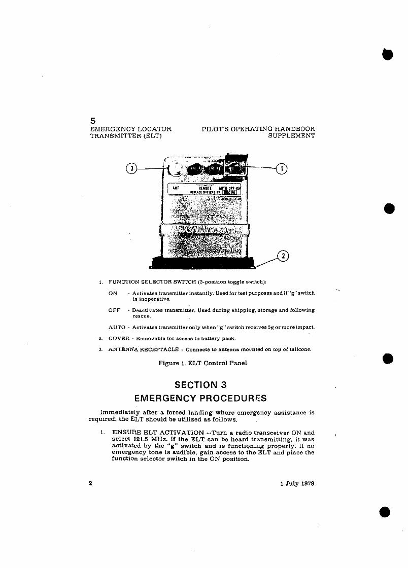
5 EMERGENCY LOCATOR PILOT'S OPERATING HANDBOOK TRANSMITTER (ELT) SUPPLEMENT
1. FUNCTION SELECTOR SWITCH (3-position toggle switch):
ON - Activates transmitter instantly. Usedfor test purposes andif"g"switch IS inoperative.
OFF - Deactivates transmitter. Used during shipping, starage and rallowing rescue.
AUTO - Activates transmitter only when "g" switch receives 5gor moreimpact.
2. COVER - Removable for access to battery pack.
3. ANTENNA RECEPTACLE - Connects to antenna mocnted on top of tailcane.
Figure 1. ELT Control Panel
SECTION 3 EMERGENCY PROCEDURES
Immediately after a forced landing where emergency assistance is required, the ELT should be utilized a s follows.
1. ENSURE ELT ACTIVATION --Turn a radio transceiver ON and Select 121.5 MHz. If the ELT can be heard transmitting, it was activated by the "g" switch and is functigni1:~g properly. If no emergency tone is audible, gain access to the ELT and place the function selector switch in the ON position.
1 July 1979

5 PILOT'S OPERATING HANDBOOK EMERGENCY LOCATOR SUPPLEMENT TRANSMITTER (ELT)
2. PRIOR TO SIGHTING RESCUE AIRCRAFT -- Conserve airplane battery. Do not activate radio transceiver.
3. AFTER SIGHTING RESCUE AIRCRAFT -- Place ELT function selector switch in the OFF position, preventing radio interference. Attempt contact with rescue aircraft with the radio transceiver set to a frequency of 121.5 MHz. If no contact i s established. return the function selector switch to ON immediately.
4. FOLLOWING RESCUE - - PlaceELTfunction selector switch in the OFF position, terminating emergency transmissions.
SECTION 4 NORMAL PROCEDURES
As long a s the function selector switch remains in the AUTO position. the ELT automatically activates following an impact of 5g or more over a short period of time.
Following a lightning strike, or an exceptionally hard landing, the ELT may activate although no emergency exists. To check your ELT for inadvertent activation. select 121.5 MHz on your radio transceiver and listen for a n emergency tone transmission. If the ELT can be heard transmitting, place the function selector switchin the OFFpositionand the tone should cease. Immediately place the function selector switch in the AUTO position to re-set the ELT foi normal operation.
SECTlON 5
PERFORMANCE
There is no change to the airplane performance data when this equipment i s installed.
1 July 1979 31 (4 blank)

PILOT'S OPERATING HANDBOOK SUPPLEMENT
CESSNA 300 ADF (TYPE R-546E)
SUPPLEMENT
CESSNA 300 ADF (Type R-546E)
SECTION I GENERAL
The Cessna 300 ADF is a panel-mounted, digitally tuned automatic direction finder. It i s designed to provide continuous 1 kHz digital tuning in the frequency range of 200 kHz to 1.699 kHz and eliminates the need for mechanical band switching. The system is comprised of a receiver, a bearing indicator. aloop antenna, and asense antenna. Operatingcontrols and displays for the Cessna 300 ADF are shown and described in Figure 1. The audio system used in conjunction with t h i ~ radio for speaker-phone selection is shown and described in Section 7 of this handbook.
The Cessna 300 ADF can be used for posi;ion plotting and homing procedures. and for aural reception of amplitude-modulated (AM) signals.
With the function selector knob at ADF,the Cessna300ADFprovides a visual indication, on the bearing indicator, of ths bearing to the transmit- ting station relative to the nose of the airplane. ::'his i s done by combining signals from the sense antenna with signals from the loop antenna.
With the function selector knob at REC, the Cessna 300 ADF uses only the sense antenna and operates a s a conventional low-frequency receiver.
The Cessna 300 ADF is designed to receive transmission from the following radio facilities: commercial AM troadcast stations. low- frequency range stations, non-directional radio beacons. ILS compass locators.
SECTION 2
LIMITATIONS There is no change to the airplane limibations when this avionic
equipment is installed.
1 July 1979 1 of 8

6 CESSNA 300 ADF (TYPE R-546E)
PILOT'S OPERATINO HANDBOOK SUPPLEMENT
1. OFFIVOI. CONTROL - Controls primary power and audio output level. Clock- wise rotstion fmm OFF position applies primary power to receiver: further clockwisw rotation inoressea audio level.
2. FREQUENCY SELECTORS - Knob [A) seleots IW-kHz increments of receiver frequency, lmob [B) seiscts 10-kHz increments, and knob (C) selects 1 kHz increments.
Figure 1. Cessn 3 300 ADF Operating Controls and Inlicators (Sheet 1 of 2)
2 1 July 1979

PILOT'S OPEilATING HANDBOOK SUPPLEMENT
3. FUNCTION SWITCH:
6 CESSNA 300 ADF
(TYPE R-546E)
BFO: Selects operation as communication receiver using only sense antenna and activates 1000-Hz tons beat frequency oscillator to pslmitcoded identifier of stations transmitting keyed CW signals (Morse Code) to be heard.
REC: Selects operation asstandardcommunicationr miver usingonly sense antenna.
AD?: Set operates a s automatic direction finder using loop and sense anten- nas.
TEST: Momentary-on position used during ADF oyerstion to test bearing reliability. When held in TEST position. slews indicator pointer oiookwise: when released. if bearing is relia.bie. pointer returns to original bearing position.
4. INDEX (ROTATABLE CARD) - Indicates relative, magnetio, or true heading of aircraft, ns selected by HDCI control.
5. POINTER - Indimtes station bearing in degrees of aeimuth. relative to thenose of the airoraft. When heading control i s adjusted, indicates relative, magnetic, or true bearing of radio signal.
8. HEADING CARD CONTROL (HDG) - Rotates card to set in relative, magnetic.or true bearing inlormation.
I
1 July 1979
6 CESSNA 300 ADF (TYPE R-546E)
PILOT'S OPERATING HANDBOOK SUPPLEMENT
SECTION 3
EMERGENCY PROCEDURES There i s no change to the airplane emergency procedures when this
avionic equipment is installed.
SECTION 4
NORMAL PROCEDURES TO OPERATE AS A COMMUNICATIONS RECEIVER ONLY:
1. OFFIVOL Control - - ON. 2. Function Selector Knob -- REC. 3. F~equency Selector Knobs - - SELECT opernting frequency. 4. AL>F SPEAKERIPHONE Selector Switch (on audio control panel)
-- SELECT speaker o r phone position a s desired. 5. VOT, Control --ADJUST to desired listening level.
TO OPERA1 E AS AN AUTOMATIC DIRECTION FINDER:
1. OFFIlrOL Control -- ON. 2. Frequency Selector Knobs -- SELECT operating frequency. 3. ADF Si7EAKERIPHONE Selector Switch (on audio control panel)
- - SELECT AS DESIRED. 4. Function Selector Knob -- ADF ~ o s i t i o n and note relative bearing
TO TEST RELIAIIILITY OF AUTOMATIC DIRECTION FINDER:
1. Function Selector Knob -- ADF position and note relative bearing on indicator.
2. Function St-lector Knob --TEST position and observe that pointer moves away from relative bearing a t least 10 to 20 degrees.
3. Function Selector Knob -- ADF position and observe that pointer returns to same relative bearing a s i n step (1).
TO OPERATE BFO: -.
1. OFFIVOL Control -- ON. 2. Function Selector Knob -- BFO. 3. Frequency Selector Knobs -- SELECT operating frequency. 4. ADF SPEAKERIPHONE Selector Switch (on audio control panel)
-- SELECT speaker or phone position a s desired.
4 1 July 1979

PILOT'S OPERATING HANDBOOK SUPPLEMENT
6 CESSNA 300 ADF
(TYPE R-546E)
5. VOL Control -- ADJUST to desired listening level.
NOTE
A 1000-Hz tone is heard in the audio output when a CW signal (Morse Code) i s tuned in properly.
SECTION 5
PERFORMANCE There is no change to the airplane performance when this avionic
equipment is installed. However, the installation of an externally mounted antenna or related external antennas, will result in a minor reduction in cruise performance.
1 July 1979 5 / (6 blank)

SUPPLEMENT
CESSNA 300 NAV/COM (720-Channel - Type RT-385A)
SECTION 1
GENERAL The Cessna 300 NavlCom (Type RT-385A). shown in figure 1. consists
of a panel-mounted receiver-transmitter and a single o r dual-pointer remote course deviation indicator.
The- set. includes a 720-channel VHF communications receiver- transmitter and a200-channel VHF navigation receiver. both of whiqhmay be operated simultaneouslv. The communications receiver-transmitter receives and transmits sign& between 118.000 s n d 135.975 MHz i n 2 5 ; k ~ z steps. The navigation receiver receives omni and localizer signals between 108.00 and 117.95 MHz in 50-kHz stem. The circuits required to interpret the omni and localizer signals are located in thecourse dkvii)tlon indicator. Both the communications and navigation operating frequencies are digitally displayed by incandescent readouts o n ihe iron? psiel 4 the NavlCom.
A DME receiver-transmitter or a glide slope receiver, or both. may be interconnected with the NavICom set for automatic selection o f ' the associated DME or glide slope frequency. When a VOR frequency is selected on the NnvlCom. associated VORTAC o r VOR-DME station frequency will alscn be selected automatically: likewise. if a localizer frequency is seluctc~l. the associated glide slope will be selected automati- cally.
-
The course deviation indicator includes either a single-pointer and related NAV f l a g f a ~ r VORILOC indication ~ n l y , o r d u & ~ o i n t e r s and related NAV and G':. flags for both VORILOC and glide slope indications. Both types of course deviation indicators incorporate a non-functional back-course l a m p (BC). Both types may be provided wi th Automatic Radial Centering *vhich, depending on how it i s selected. will automati- cally indicate the oearing TO or FROM the VOR statiou.
1 July 1979

7 CESSNA 500 NAVICOM PILOT'S OPERATING HANDBOOK (TYPE RT-385A) SUPPLEMENT
1. COMMUNICATION OPERATING FREQUE!.(CY READOUT (Third-decimal. place i s shown by the position of the "5-0" switch).
2. 5-0 SWITCH - Part of Corn Receiver-Transmitter Fractional MHz Frequency Selector. In "5" position, enables Corn frequanay repdout to display and Com Fractional MHz Selector to select frequency in .O5-MHz steps between ,025 and ,975 MHz. In "0" position. enables COM freqrsncy readout to display and Cam Fractional MHz Selector to seleot frequency l a .05-MHz steps between ,000 and ,950 MHa. !
NOTE
The "5" or "0" may be read as the third dec!nal digit. which is not displayed in the Corn fractional frequency ,:lisplay.
Figure 1. Cessna 300 NavlCom (Type RT-385~). Operating Controls and Indicators (Sheet 1 of 3)
1 July 1979

7 PILOT'S OPERATING HANDBOOK CESSNA 300 NAVICOM SUPPLEMENT (TYPE RT-385A)
3. NAVIGATION OPERATING FREQUENCY READOUT
4. ID-VOX-T SWITCH - With VOR or LOC Station selected. in ID position. station identifier signal i s audible: in VOX (Voice) position. identifier signal is sup- pressed: In T (Momentary On) position. the~~dnsvlgationslself-test lunction is selected.
5 . NAVIGATION RECEIVER FRACTIONAL MEGAHERTZ SELECTOR - Selects NBV frequency in US-MHz s teps botween 00 and .85 MHz: simultaneously selecrs paired glide +pe frequency and DME channel
8. NAV VOL C0,NTROL - Adjusts volume of navigation receiver audio
7. NAVIOATION RECEIVERMEGAHERTZ SELECTOR - Selects NAV frequency in 1-MHz step? between 108 and 117 MHz: simultaneously selects paired giide slope lrequenc'y and DME channel.
8. COMMUNICATION RECEIVER-TRANSMITTER FRACTIONAL MEGAHERTZ SELECTOR - Depending on position of 5-0 switch. selects COM frequency in .05- MHz s t a m between ,000 and ,975 MHz. The 5-0 switch identifies the last digit as either 5 br O.
9. SQUELCH CONTROL - Used to adjust signal threshold noccssnry to nctrvnte COM recatver audio. Clockwise rotation i n c r e n s e ~ b e c k ~ r o u n d nmse (deerensas squelch action); counterclockwise rotation decreases background noise.
10. COMMUNICAT1I)N RECEIVER-TRANSMITTER MEGAHERTZ SELECTOR Selects COM f r q u e n c y In 1-MHz s t eps between 118 and 135 MHz.
11. COM OFF-VOL CONTROL - Combination onloif switch and volume control: turns on NAVICOM set and controls volume of communications receiver audio.
3 12. BC LAMP - Non.operstiana1 on 152 ser ies aircraft.
13. COURSE INDEX - Indicates selected VOR course
14. COURSE DEVIIhTION POINTER - Indicates course deviation from selected omni course or 1:lcaliser centerline.
15. GLIDE SLOPE "GS" FLAG - When visIb1e.red GS flag indicates unreliable giide slope signal or improperly operatIngequipment.Flagd1sappearswhen areliable glide slope signal i s being received.
16. GLIDE SLOPE DEVlATION POINTER - Indicates deviation from ILS glide slope.
, 17. NAVITO-FROM INDICATOR - Operates only with a VOR or laeslizer signal. Red NAV position (Flag) indicates unusable signal. With usable VOR signal. Indicates whether selected course I s T O or FROM station. With usable loeslizer signal. shows TO.
18. RECIPROCAL COURSE INDEX - Indicates reciprocal of selected VOR course.
Figure 1. Cessna 300 NavlCom (Type RT-385A). Operating Controls and Indicators (Sheet 2 of 3)
1 July 1979 3

7 CESSNA 300 NAVICOM PILOT'S OPERATING HANDBOOK (TYPE RT-385A) SUPPLEMENT
19. OMNI BEARING SELECTOR (OBS) - Rotates course card to select desired COUTSB.
20 AUTOMATIC RADIAL CENTERING IARC-PUSll.TO! PULL.FR1 SEI.ECTOR . In center detcnt. functmns asconvont!onnl OBS. Puzhedto nnner Ihlomentar\ , 0111
ponltion. t u rn s ORS course card to center course devlntmn pointer wtth n 'rO f lnc . then rc turns to convcntwnnl OBS select~ort l'ullcd to outer delent ronlmtrous.y drlves OBS course card lo mdrcate bcartnq from VOR statlon. keepnng coursr devmllon Dolnter centered. with a FHOM flnz ,\RC Iunctrun will not ooera te on
2 1 AUTOMATIC RADIAL CENTERING (ARC) LAMP Ambcr lrgnt i l lumlnnles when Automatic Radrill Centerma 1s In use Light d rmm~np , 1s only nvx~1ab.e wtwn m ~ t i l l l ~ r i wtth an audm eontml oan r l lncoroorntme the annuncantor I h ~ h l s - DAYINITE selector switch.
22. COURSE CARD - Indicates selected VOR course under course index.
1 July 1979

PILOT'S OPERATING HANDBOOK SUPPLEMENT
CESSNA 300 NAVICOM (TYPE RT-385A)
The Cessna 300 NavlCom incorporates avariable threshold automatic squelch. With this squelch system. you set the threshold level for ayto- matic operation - the further clockwise the lower the threshold - or the more sensitive the set. When the signal i s above this level. it i s heard even if the noise i s very close to the signal. Below this Level. the squelch is fully automatic s o when the background noise i s very low, very weak SigIplS (that are above the noise) are let through. For normal operation of'the squelch circuit. just turn the squelch clo6kwlse untll nolse 1s heard -then back off sllphtly llntll it 1s quiet. and you will haveautomatlc~quelch vjlth - - the lowest practical threshold. his adjustment should be rechecred periodically during each flight to assure optimum reception.
All c o n t r o l s for the NavlCom, except the standard omni bearing selector (OBS) knoljor the o ~ t i o n a l automatic radial centering (ARC) knob ~ -, located on the cnurse deviat;on indncator, are mountedon thc trnnt panel of the rccelver-transmitter. Ooeratlon and dcscrlptlon of the transmltterlau- dio switching system or aidiocontrol panel used inconjuni:tion with this radio is shown and described in Section 7 of this handbook.
, SECTION 2 LIMITATIONS
There i s no change to the airplane limitations when this avionic equipment is installed.
SECTION 3 EMERGENCY PROCEDURES
There is no change to the airplane emergency procedures when this avionic equipment i s installed. However, if the frequency readouts fail. the radio will remain operational on the last frequency selected. The fre- quency control should not he moved due to the,difficulty of obtaining a known frequency under this condition.
1 July 1979

7 CESSNA 300 NAVICOM PILOT'S OPERATING HANDBOOK (TYPE RT-385A) SUPPLEMENT
SECTION 4
NORMAL PROCEDURES COMMUNICATION RECEIVER-TRANSMITTER OPERATION:
1. COM OFFIVOL Control -- TURN ON: adiust to desired audio level. 2. XMTR SEL Switch (on audio control panel) -- SET to desired
NavICom Radio. 3. SPEAKERIPHONE Selector Switches (on audio control panel) --
SET to desired mode. 4. 5-0 Fractional MHz Selector Switch - - SELECT desired operating
frequency (does not affect navigation frequencies). 5. COM Frequency Selector Switch -- SELECT desired operating
frequency. 6. SQ Control -- ROTATE counterclockwise to just eliminate back-
ground noise. Adjustment should be checked periodically to assure optimum reception.
7. Mike Button: a. To Transmit -- DEPRESS and SPEAK into microphone.
NOTES
When the transmitterlaudio switchin: panel without marker beacon is installed, sidetone is available with either SPEAKERor PHONE operation. A SIDETONE VOL control i s provided that may be used to adjust or suppress speaker sidetone.
When the audio control panel with marker beacon is installed. sidetone may be selected oy placing the AUTO selector switch in either the SPEAKER or PHONE posi- tion. Sidetone may be eliminated by placing the AUTO selector switch in the OFF position. Adjustment of either SPEAKER or PHONE sidetone may be accomplished by adjusting the sidetone pots, which are accessible through the front of the audio control panel, with a small screw- driver.
b. To Receive -- RELEASE mike button. <
NAVIGATION OPERATION:
1. COM OFFIVOL Control -- TURN ON. 2. SPEAKERIPHONE Selector Switches (on audio control panel) --
SET to desired mode.
6 1 July 1979

7 PILOT'S OPERATING HANDBOOK CESSNA 300 NAVICOM SUPPLEMENT (TYPE RT-385A)
3. NAV Frequency Selector Knobs -- SELECT desired operating frequency.
4. NAV VOL -- ADJUST to desired audio level. 5. ID-VOX-T Switch:
a. To Identify Station -- SET to ID to hear navigation station identifier signal.
b. To Filter Out Station Identifier Signal -- SET toVOX to include filter in audio circuit.
6. ARC PUSH-TOIPULL-FROM Knob (If Applicable): a. To Use As Conventional OBS -- PLACE in center detent and
select desired course. b. To Obtain Bearing TO VOR Station -- PUSH (ARCIPUSH-TO)
knob to inner (momentary on) position.
NOTE
ARC l a m p will illuminate amber while the course card is m o v i n e to center with the course deviation pointer. After alignkent has been achieved to reflect bearing to VOR. automatic radial centering will automatically shut down. causing the ARC lamp to go out.
c. To Obtain Continuous Bearing FROM VOR Station -- PULL (ARCIPULL-FR) knob to outer detent.
NOTE
ARC l a m p will illuminate amber. OBS course card will turn to center the course deviation pointer with a FROM flag to indicate bearing from VOR station.
7. OBS Knob (If Applicable) - - SELECT desired course.
VOR SELF-TEST OPERATION:
1. COM OFFIVOL Control - - TURN ON. 2. NAV Frequency Selector Switches -- SELECT usable VORstation
signal. 3. OBS Knob -- SET fo- O0 course at course index: course deviation
pointer centers o r deflects left or right, depending on bearing of signal: NAVITO-FROM indicator shows TO or FROM.
4. IDIVOXIT Switch -- I'RESS to T and HOLD a t T: course deviation pointer centers and N.lV/TO-FROM indicator shows FROM.
5. OBS Knob --TURN to displace course approximately lo0 to either side of Oo (while holdiny IDIVOXIT toT). Coursedeviation pointer deflects full scale in di~ection corrtsponding to course displace- ment. NAVITO-FROM indicator shows FROM.
1 July 1979 7

7 CESSNA 300 NAVICOM PILOT'S OPERATING HANDBOOK (TYPE RT-385A) SUPPLEMENT
6. IDIVOXIT Switch -- RELEASE for normal operation
NOTE
This test does not fulfill the requirements of FAR 91.25.
SECTION 5
PERFORMANCE There is no change to the airplane performance when this avionic
equipment is installed. However. the installation of an externally mounted antenna or several related external antennas, will result in a minor reduction in cruise performance.
1 July 1979

8 PILOT'S OPERATING HANDBOOK CESSNA 300 TRANSPONDER SUPPLEMENT AND ALTITUDE ENCODER (BLIND)
CESSNA 300 TRANSPONDER (Type RT-359A)
AND , OPTIONAL ALTITUDE ENCODER (BLIND)
SECTION 1
GENERAL The Cessna 360 Transponder (Type RT-359A). shown in Figure 1, is the
airborne component of an Air Traffic Control Radar Beacon System (ATCRBS). The transponder enables the ATC ground controller to "see" and identify the aircraft, while in flight. on the control center's radarscope more readily.
The Cessna 300 Transponder system consists of'a panel-mounted unit and an externally mounted antenna. The transponder receives interroga- tion pulse signnls on 1030 MHz and transmits pulse-train reply signals on 1090 MHz. The transponder i s capable of replying to Mode A (aircraft identification) a.nd also Mode C (altitude reporting) when coupled ta an optional altitude encoder system. The transponder i s capable of replying on both modes of interrogation on a selective reply basis on any of4.096 information code selections. The optional altitude encoder system (not part of a standard 300 Transponder system) required for Mode C (altitude reporting) operation consists of a completely independent remote- mounted digitizer that is connected to the static system and supplies encoded altitude information to the transponder. When the altitude encoder system is coupled to the 300 Transponder system, altitude reporting capabilities a r e available in 100-foot increments between -1000 snd+20.000 feet.
All Cessna 300 Transponder operating controls are located on the front panel of the unit. Functions of the operating controls are described in Figure 1.

8 CESSNA 300 TRANSPONDER PILOT'S OPERATING HANDBOOK AND ALTITUDE ENCODER (BLIND) SUPPLEMENT
1. FUNCTION SWITCH - Controls application of paaer and selects transponder operating mode as follows:
OFF - Turns set off. S B Y - Turns set on for equipment warm-up or standby power. ON - Turns set on and enables transponder to transmit Mode A (aircraft
identification) reply pulses. ALT - Turns set on and enables transponder to trinsmit eitherMode A(aircraft
identification) reply pulses or Mode C (altitude reporting) pulses selected automatically by the interrogating signal.
2 REPLY LAMf' - Lamp llashes to indicate translnlsslon of rrply pulses. glows siead~lg lo indicate lransmlssion of IUENT pulrc c l ' ratlsfnctory sell-trst opera- t w n . (Reply lamp w ~ l l also glow steadily durmp, iultinl warm-up permd )
Figure 1. Cessna 300 Transponder a n d Alti thde Encoder (Blind) . (Sheet 1 of 2)
2 1 July 1979
- P I L O T 5 OPERATING HANDBOOK CESSNA 300 TRANSPONDER SUPPLEMENT AND ALTITUDE ENCODER (BLIND)
3, IDENT (ID) SWITCH - When depressed, selects special pulse identifier to be transmitted with transponder reply to effect immediate identification of aircrnft on sroundcontroller'sdisolsy. ( R e ~ l y l a m p will glow steedilyduringdurstionoI
4. DIMMER (DIM) CONTROL - Allows pilot to control brilliance of reply lsmp.
5 . SELF-TEST (TST) SWITCH -When depressed. bsuses transponder to generate s self-interrogating signal to provide a check of transponder operatlo". (Reply Lamp wkil glow s t e d i l y to verify self-test operation.)
6 . REPLY-C&E SELECTOR KNOBS (4) - Select assigned Made A reply code
7. REPLY -CODE INDICATORS (4) - Display selected Mode A reply code.
8. REMOTE-MOUNTED DIGITIZER - Provides an altitude reporting code range of -1M10 fm:t u p to the airplane's maximum service ceiling.
Figure 1. Cessna 300 Transponder a n d Alti tude Encoder (Blind) (Sheet 2 of 2) .
1 Ju ly 1979 3

8 CESSNA 300 TRANSPONDER PILOT'S OPERATING HANDBOOK AND ALTITUDE ENCODER (BLIND) SUPPLEMENT
SECTION 2
LIMITATIONS There i s no change to the airplane limitations when this avionic
equipment i s installed. However, the following information mus t be displayed in the form of a placard located near the altimeter.
ALTITUDE ENCODER EQUIPPED _I
SECTION 3
EMERGENCY PROCEDURES TO TRANSMIT AN EMERGENCY SIGNAL:
1. Function Switch -- ON. 2. Reply-Code Selector Knobs - - SELECT 7700 operat ing code.
TO TRANSMIT A SIGNAL REPRESENTING LOSS OF ALL COMMUNICATIONS (WHEN IN A CONTROLLED ENVIRONMENT):
1. Function Switch -- ON. 2. Reply-Code Selector Knobs - - SELECT 7700 operat ing code for 1
minute: then SELECT 7600 operat ina code for 15 minutes and then REPEAT this procedure a t s ame intervals for remainder of flight.
SECTION 4
NORMAL PROCEDURES BEFORE TAKEOFR
1. Function Switch -- SBY.
TO TRANSMIT MODE A (AIRCRAFT IDENTIFICATION) CODES IN FLIGHT:
1. Reply-Code Selector Knobs -- SELECT i ss igned code,
4 1 July 1979

8 PILOT'S OPERATING HANDBOOK CESSNA 300 TRANSPONDER SUPPLEMENT AND ALTITUDE ENCODER (BLIND)
2. Function Switch -- ON. 3. DIM Control - - ADJUST light brilliance of reply lamp.
-. 4. TST Button -- Release for normal operation.
NOTE
During normal operation with function switch in ON position. reply lamp flashes indicating transponder rep- lies to interrogations.
4. ID Button - - DEPRESS momentarily when instructed by ground controller to "squawk IDENT" (reply lamp will glow steadily, indicating IDENT operation).
TO TRANSMIT MODE C (ALTITUDE REPORTING) CODES IN FLIGHT:
1. Replg-Code Selector Knobs -- SELECT assigned code 2.- Funcr.ion Switch -- ALT.
NOTE
Wher, directed by ground controller to "stop altitude squawk". turn.Function Switch to ON for Mode A opera- tion only.
NOTE
pressure altitude is transmitted by the transponder for altitcde squawk and conversion to indicated altitude is done i n ATC computers. Altitude squawked will only agree' with indicated altitude when the local altimeter setting i n use by the ground controller is set in the aircraft altimeter.
3. DIM 'Jontrol -- ADJUST light brilliance of reply lamp
TO SELF-TEST TRANSPONDER OPERATION:
1. Function Switch -- SBY and wait 30 seconds for equipment to warm-up.
2. Function Switch -- ON or ALT. 3. TSL' Button - - DEPRESS (reply lamp shoulcl'light brightly regard-
less of DIM control settine).
1 July 1979

8 CESSNA 300 TRANSPONDER PILOT'S OPERATING HANDBOOK AND ALTITUDE ENCODER (BLIND) SUPPLEMENT
SECTION 5 PERFORMANCE
There is no change to the airplane performance when this avionic equipment i s installed. However, the installation of a n externally mounted antenna or several related external antennas, will result in a minor reduction in cruise performance.
1 July 1979

9 PILOT'S OPERATING HANDBOOK CESSNA 300 TRANSPONDER SUPPLEMENT AND ENCODING ALTIMETER
SUPPLEMENT
CESSNA 300 TRANSPONDER (Type RT-359A)
AND OPTIONAL ENCODING ALTIMETER
(Type EA-40 1 A)
SECTION 1
GENERAL 'The Cessna 300 Transponder (Type RT-359A). shown in Figure 1, i s the
airborne component of a n Air Traffic Control Radar Beacon System (ATCHRS). The transponder enables the ATC ground controller to "see" and ideutify the aircraft, while in flight, on the control center's radarscope more readily.
The Cessna 300 Transponder consists of a panel-mounted unit and an externally mounted antenna. The transponder receives interrogating pulse signals on 1030 MHz and transmits coded pulse-train reply signals on 1090 MHz. It i s capable of replying to Moda A (aircraft identification) and Mode C (altitude reporting) interrogationa on a selective reply basis on any of 4.L'96 information code selections. When an optional panel- mounted EA-40lA Encoding Altimeter (not part of a standard 300 Trans- ponder system) is included in the avionic configuration, the transponder can provide altj kude reporting in 100-foot increments between -1000 and +35.000 feet.
All Cessna 30Cl Transponder operating controls, with the exception of the optional altitude encoder's altimeter setting knob. are located on the front panel of the unit. The altimeter setting knob is located on the encoding altimeter. Functions of the operating controls are described in Figure 1.
1 July 1979

9 CESSNA 300 TRANSPONDER PILOTS OPERATING HANDBOOK AND ENCODING ALTIMETER SUPPLEMENT
I. FUNCTION SWITCH - Contmls application of power and selects transponder operatlog mods a s follows:
OFF - Turns set off. SBY - T u n s set on far equipment warm-up. ON - Turns set O. and enables trampander to trahsrnit Mode A (aircraft
, identification) reply pulses. ALT - Turns set an and enables trabepuudar to tranomit either Mnde A (aircraft
identification) reply pulses or Mode C (altitude reporting) pulses selected autornaticaUy by the Lnterrogating signal.
2. REPLY LAMP - Lamp nashes u, mllcate transmission of reply pulses: glows steadtly to indicato transmisalon a! ;DEP.;T pulse or ratisfactory self-test opera. t ~ o n (Reply Lamp w ~ l l also glow r'aadily d u n n ~ ~nrtial warn-up period.)
Figure 1. Cessna 300 Transpondar and Encoding Altimeter (Sheet 1 of 2)
2 1 July 1979

9 PILOT'S OPERATING HANDBOOK CESSNA 300 TRANSPONDER SUPPLEMENT AND ENCODING ALTIMETER
3. IDENT (ID) SWlTCH - When depressed. selects special pulse identifier to be transmitted with transponder reply to effect immediate identification of aircraft on groundcontroller'sdisplay. (Reply Lamp will glow steadily duringdurvtionof IDENT pulse transmission.)
4. DIMMER (DIM) CONTROL - Allows pilot to control brilliance of reply lamp
5. SELF-TEST (TST) SWITCH - When depressed. causes transponder to generate a self-intarrogating signal to provide a check of transponder operation. (Reply Lamp m l l glow steadily to verify self test operation.)
6. REPLY-CODE SELECTOR KNOBS (4) - Select assigned Mode A reply code.
7. REPLY-CODE INDICATORS (4) - Display selected Mode. A reply code.
f l 10W.FOOT DRUM TYPE INDICATOR -Prov ldesd lg~ ta l sltttude rendout in 1000- foot mcrements between -IOU0 feet and ,35.WO feet. When ?.lt~tude rs below 10 OW feet. 3 d lagon~l ly strlped flag appears in the IO.OW foot clndow
9. OFF INDICATOR WARNING FLAG - Flag appears across altitude readout when power is removed from the altimeter to indicate that readout i s not reliable.
10. 100-FOOT DRUM TYPE INDICATOR - Provides digital altitude readout in 100- foot increments between 0 feet'and 1000 feet.
11. 20-FOOT INDICATOR NEEDLE - Indicates altitude in 20-foot inciements betweea 0 feet and.1000 feet.
12. ALTIMETER SETTING SCALE - DRUM TYPE - Indicates selected altimeter setting In the range 0127.9 to 31.0inches of mercury on thestandsrdaltimeteror 950 to 1050 millibars on the optional altimetar.
13. ALTIblETER SETTING KNOB - Dials in desired altimeter setting in the range of 27.9 to 31.0 inches01 mercury on the standard altimeter or 950 to 10BOmillibarson the optional altimeter.
SECTION 2 LIMITATIONS
There is no change to the airplane performance when thir: avionic equipmen!; i s instal led. However, the encodingal t imeter usedin th i s installation does have a limitation that requires a standard barometric altimeter to be installed a s a back-up altimeter.
Figure 1. Cessna 300 Transponder and Encoding Altimeter (Sheet 2 of 2)
1 Ju ly 1979 3

9 CESSNA 300 TRANSPONDER PILOT'S OPERATING HANDBOOK AND ENCODING ALTIMETER SUPPLEMENT
SECTION 3 EMERGENCY PROCEDURES
TO TRANSMIT AN EMERGENCY SIGNAL:
1. Function Switch -- ON. 2. Reply-Code Selector Knobs -- SELECT 7700 operating code.
TO TRANSMIT A SIGNAL REPRESENTING LGSS OF ALL COMMUNICATIONS (WHEN IN A CONTROUED ENVIRONMENT):
1. Function Switch -- ON. 2. Reply-Code Selector Knobs -- SELECT 7700 operating code for 1
minute: then SELECT 7600 operating codo for 15 minutes and then REPEAT this procedure at same intervals for remainder of flight.
SECTION 4 NORMAL PROCEDURES
BEFORE TAKEOFF:
1. Function Switch -- SBY. TO TRANSMIT MODE A (AIRCRAFT IDENTIFICATION) CODES IN FLIGHT:
1. Reply-Code Selectot Knobs -- SELJlOT a3:ligned code. 2. Function Switch -- ON. 3. DIM Control -- ADJUST light brilliance 0.' reply lamp.
NOTE
During normal operation with function switch in ON position, reply lamp flashes indicating transponder re- plies to interrogations.
1 July 1979

PIL0'I"S OI'CIIATING IIANDBOOK CESSNA 300 TRANSt'ONDER SUPPLEhlENT AND ENCODING ALTlhlETER
4. ID Button - - DEPRESS momentarily when instructed by ground controller to "squawk IDENT" (reply lamp will glow steadily. indicating IDENT operation).
TO TRANSMIT MODE C (ALTITUDE REPORTING) CODES INFLIGHT:
1. Off Indicator Warning Flag -- VERIFY that flag i s out of view on encoding altimeter.
2. Altitude Encoder Altimeter Se t t ins Knob -- SET IN assiEned local .. u
altimeter setting. 3. Reply-Code Selector Knobs -- SELECT assigned code. - 4. Fuhciion Switch -- ALT.
NOTE
When directed by ground controller to "stop altitude squawk", turn Function Switch to ON for Mode A opera- tion only.
NOTE
Pressure altitude i s transmitted by the transponder for altitude squawk and conversion lo indicated altitude is accomplished i n ATC computers. Altitude squawked will only agree with indicated altitude when thelocalaltimeter s e t t i n g i n u s e by t h e g r o u n d c o n t r o l l e r i s s e t i n t h e encoding altimeter.
5. DIM Control -- ADJUST light brilliance of reply lamp.
TO SELF-TEST TRANSPONDER OPERATION:
1. Function Switch -- SBY and wait 30 seconds for equipment to warm-up.
2. Function Switch -- ON o r ALT. 3. TST Button -- DEPRESS and HOLD (reply lamp should light with
full brilliance regardless of DIM coritrol setting). 4. TST Button -- Release for normal operation.
SECTION 5
PERFORMANCE There i s no change to the airplane perfomlance when this avionic
equipment i s installed. However, the installation of a n externally mounted antenna o r several related external antennas, will result in a minor reduction in cruise performance.
1 July 1979 5 / ( 6 blank)

PILOT'S OPERATING HANDBOOK CESSNA 400 GLIDE SLOPE SUPPLEMENT (TYPE R-4438)
SUPPLEMENT CESSNA 400 GLIDE SLOPE
(Type R-443B)
SECTION 1 GENERAL
The Cessna 400 Glide Slope is an airborne navigation receiver which receives and interprets glide slope signals from a ground-based Instru- ment Landing System (ILSI. It i s used with the localizer function of a VHF . . navigation system when making instrument approaches to an airport. The glide slope provides vertical path guidance while the localizer provides horizon ti^ tiack guidance. -
The Cessna 400 Glide Slope system consists of a remote-mounted receiver coupled to an existing navigation system, a panel-mounted indicator and an externally mounted antenna. The glide slope receiver is designed to receive ILS glide slope signals on any of 40 channels. The channels are spaced 150 kHz apart and cover a frequency range of 329.15 MHz through335.0 MHz. When a localizer frequency is selected on the NAV receiver, the associated glide slope frequency is selected automatically.
Operation of the Cessna 400 Glide Slope system is controlled by the associated ntivipation system. The functions and indicationsof typical 300 series glide slope indic&rsarepicturedanddescribed i n ~ i ~ u r e - i . ~ h e 3 0 0 series glide slope indicators shown in Figure 1 depict typical indications for Cessna-crafted glide slope indicators. However, refer to the 400 NavlCorn or IISI write-ups if they are listed in this section as options for additional glide slope indicators.
SECTION 2 LIMITATIONS
There is no change to the airplane limitations when this avionic equipment is installed.
1 July 1979
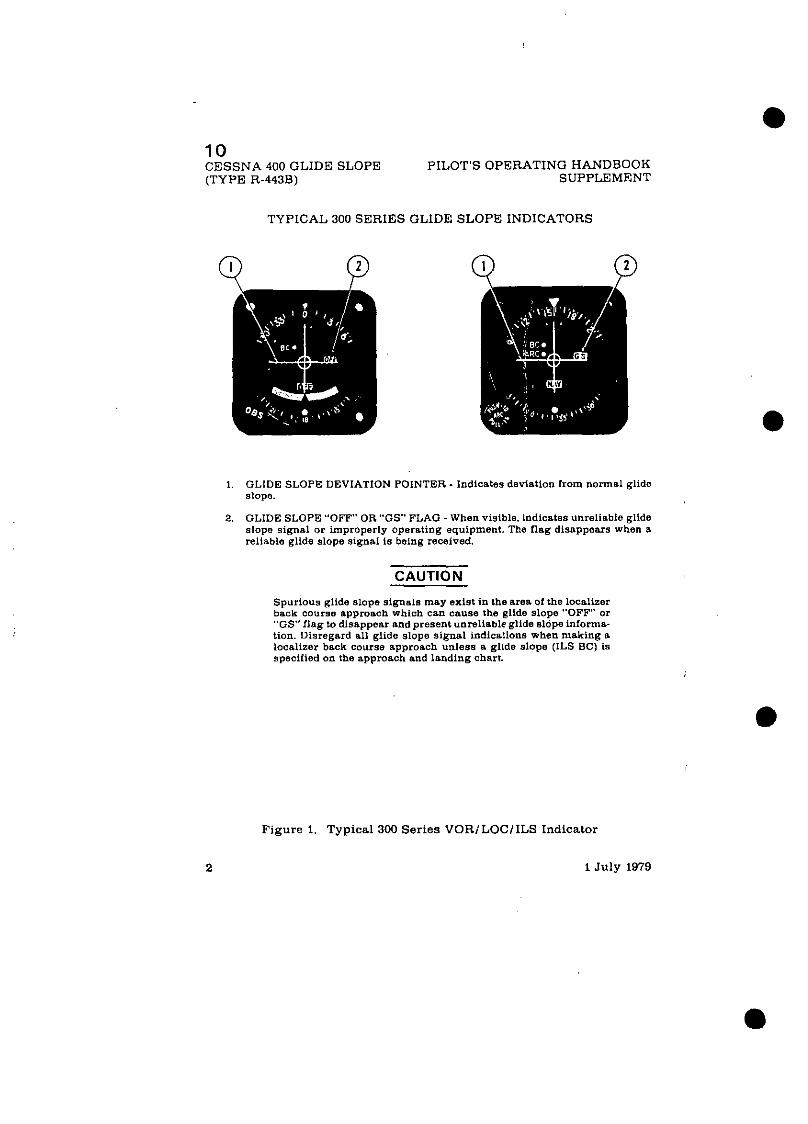
10 CESSNA 400 GLIDE SLOPE PILOT'S OPERATING HANDBOOK (TYPE R-443B) SUPPLEMENT
TYPICAL 300 SERIES GLIDE SLOPE INDICATORS
GLIDE SLOPE DEVIATION POINTER - Indicates deviation from normal glide slope.
GLIDE SLOPE "OFF" OR "GS" FLAG -When visible. lndlcates unreliable glide slope signal or improperly operating equipment. The flag disappears when a reliable glide slope signal is being received.
CAUTION
Spurious glide slope signals may exist in the area of the localizer back course approach which e m cause the ~Lide slope "OFF" or "GS" nag to disappear and present unreliable gllda slope infama- tion. Disregard all glide slope signal indicstians when making a lac8lizer back course approach unless s glide slope (ILS BC) is specified on the approach and landing chart.
Figure 1. Typical 300 Series VOR;LOC/ILS Indicator
2 1 July 1979

10 PILOT'S OPERATING HANDBOOK CESSNA 400 GLIDE SLOPE SUPPLEMENT (TYPE R-443B)
SECTION 3
EMERGENCY PROCEDURES
There is no change to the airplane emergency procedures when this avionic equipment is installed.
SECTION 4 NORMAL PROCEDURES
TO RECEIVE GLIDE SLOPE SIGNALS:
NOTE
The pilot should be aware that on many Cessna airplanes equipped with the windshield mounted glide slope antenna, pilots should avoid use of 2700 2100 RPM on airplanes equipped with a two-bladed propeller or 1800 5100 RPM on airplanes equipped with a three-bladed propeller during ILS approaches to avoid oscillations of the glide slope deviation pointer caused by propeller interference.
1. NAV Freauencv Select Knobs -- SELECT desired localizer fre- quency (giide siope frequency is automatically selected).
2. NAVICOM VOX-ID-T Switch - - SELECT ID position todisconnect filter from audio circuit.
3. NAV VOL Control -- ADJUST to desired listeninglevel to confirm proper localizer station.
CAUTION
When glide slope " O F F or "GSMflag is visible, glideslope indications are unusable.
SECTION 5
PERFORMANCE There is no change to the airplane performance when this avionic
equipment is installed.
1 July 1979 31 (4 blank)

11 PILOT'S OPERATING HANDBOOK CESSNA 400 MARKER BEACON SUPPLEMENT (TYPE R-402A)
SUPPLEMENT
CESSNA 400 MARKER BEACON (Type R-402A)
SECTION 1
GENERAL The sys tem consis ts of a remote mounted 75 MiIz marker beacon
receiver. an antenna which is externally mounted on lhe under side of the aircraft and operating controls and annunciator light!] which are mounted on the front of the audio controi panel.
Operating controls consist of two, three-position toggle switches. One switch i s laboled"HIGH/LOIMUTE" andprovides thepilotwith HIGH-LO sensitivity selection and marker beacon audio muting, for approximately 30 seconds, t , r ~ enable voice communication to be heard without interfer- ence of marker beacon signals. The marker beacon audible tone is au tomat ica l lv restored a t the end of the 30-second muting period to continue mnrcer audio for passage over the next mnrker. ~heoiherswi tch is Inbeled "SI'KR/OFF/PHN" and is used to turn the set on and select the desired speaker or phone position for marker beacon signals.
Another three-position toggle switch labeled. "ANN LT". i s provided to enable the pilot to select the desired DAY or NITE lighting position for annunciat.or lights, and also a "TEST" position to verify operation of marker beacon annunciator lights.
Whrn the Cessna 400 Marker Beacon conlrols are incorporated in an audio control panel incorporated with two or less transmitters aMarker Beacor~ audio level adjustment potentiometer and an annunciator lights minirrnurn dimming potentiometer are mounted on the audio control panel circnit board. Pot<ntiometer adjustments cannot be accomplished exter- nally. However if readjustments aredesired, adjustments can be made in ac'&dance with inst&ctions found in the Avionics Installations Ser- v (ce /Par t s Manual for this aircraft.
Operating controls and indicator lights are shown and described in Figure 1.
1 July 1979 1 of 4

11 CESSNA 400 MARKER BEACON PILOT'S OPERATING HANDBOOK (TYPE R-402A) SUPPLEMENT
MARKER FACILITIES
~~ -
MARKER IDENTIFYING TONE LIGHT*
Inner & Fan Continuous 6 dotslsec (300 Hz) White
Middle Alternate dots and dashes (1300 112) Amber
Outer 2 dasheslsec (400 Hz) Blue
When the identifying tone is keyed, the r e s p e ~ ~ i v e indicating light will blink accordingly.
SECTION 2 LI M ITATI 0 N S
There is no change to the a i rp lane l imitat ions when th is avionic equipment is installed.
There is no change to the airplane emergency procedures %'hen this avionic equipment i s installed.
1 July 1979

P I L O T S OPERATING HANDBOOK C E S S N A 400 TRANSPONDER SUPPLEMENT AND ALTITUDE ENCODER (BLIND)
3. IDENT (ID) SWITCH - When depressed. selects special pulse identifier to be transmitted with trsnsponder reply to effect immediate identification of aircraft on ground controller's display. (Reply lamp will glowstaedilyduringdurationof IDENT pulse transmission.)
4. DIMMER (DIM) CONTROL - Allows pilot to ~ 0 n t r d brilliance of reply lamp.
5 SELF-TEST(TESf) SWITCH - When deprosred. causes 1ran.pondertogoneratoa 3elf.hnterropatmg olpmsl to prowdo a check of transponder operation (Rcply lamp wnll glow srsad~ly to verlfy self-test operstlon 1
8. REPLY-CODE SELECTOR SWITCHES (4) - Select assigned Mode A reply code.
7. REPLY-CODE INDICATORS (4) - Display selected Mode A reply code.
8. REMOTE-MOUNTED DIGITIZER - Provides an altitude reportingcodersngeof - 1000 feet up to the airplane's maximum service ceiling.
F igure 1. Cessna 4LKI Transponder and Altitude Encoder (Blind) (Sheet 2 of 2)
1 Ju ly 1979 3

I L CESSNA 400 TRANSPONDER PILOT'S OPERATING HANDBOOK AND ALTITUDE ENCODER (BLIND) SUPPLEMENT
SECTION 2 LIMITATIONS
There is no change to the airplane limitations when this avionic equipment is installed. However, the following information must be displayed in the form of a placard located near the altimeter.
I ALTITUDE ENCODER EQUIPPED
SECTION 3
EMERGENCY PROCEDURES TO TRANSMIT AN EMERGENCY SIGNAL:
1. Function Switch -- ON. 2. Reply-Code Selector Switches -- SELEIT 7700 operating code.
TO TRANSMIT A SIGNAL REPRESENTING LOSS OF ALL COMMUNICATIONS (WHEN I N A CONTROLLED ENVIRONMENT):
i. Function Switch - - ON. 2. Reply-Code Selector Switches --SELEC:'7700operatingcodefor 1
minute: then SELECT 7600 operating code for 15 minutes and then REPEAT this procedure at same in t e rva .~ for remainder of flight.
SECTION 4
NORMAL PROCEDURES
BEFORE TAKEOFF:
i. Function Switch -- SBY.
TO TRANSMIT MODE A (AIRCRAFT IDENTII?ICATION) CODES IN FLIGHT:
1. Reply-Code Selector Switches -- SELECT assigned code.
4 1 July 1979

12 PILOT'S OPERATING HANDBOOK CESSNA 400 TRANSPONDER SUPPLEMENT AND ALTITUDE ENCODER (BLIND) ;
SUPPLEMENT
CESSNA 4 0 0 TRANSPONDER (Type RT-459A)
AND
OPTIONAL ALTITUDE ENCODER (BLIND)
SECTION 1
GENERAL
The Cessna 400 Transponder (Type RT-459A). shown inFigure 1. is the airborne component of an Air Traffic Control Radar Beacon System (ATCRBS). The transponder enables the ATC ground controller to "see" and identify the aircraft, while in flight. on the control center'sradarscope more readily.
The Cessna 400 ~ r a n s p o n d e r system consists of a panel-mounted unit and an externally mounted antsnna. The transponder receives interrogat- ing pulse signals on 1030 MHz and transmits pulse-train !:eply signals on 1090 MHz. The transponder i s capable of replying to Node A (aircraft identification) and also to Mode C (altitude reporting) when coupled to an optional altitude encoder system. The transponder i s capable of replying on both modes of interrogation on a selective reply basis on any of 4.096 information code selections. The optional altitude encoder system (not part of a standard 400 Transponder system) required for Mode C (altitude reporting) operation, consists of a completely indepsndent remote- mounted digitizer that is connected to the static system and supplies encoded altitude information to ihe transponder. When the :rltitude encoder system is coupled to the 400 Transponder system, alt.itude reporting capabilities are available in 100-foot increments between-t000feetand the airplane's maximum service ceiling.
1\11 Cessna 400 Transponderoperating controls are locatedon the front panel of the unit. Functions of the operating controls a te described in i Figure 1. I
1 July 1979

12 CESSNA 400 TRANSPONDER PILOT'S OPERATING HANDBOOK AND ALTITUDE ENCODER (BLIND) SUPPLEMENT
1. FUNCTION SWITCH - Controls application of power and selects transponder operating mode as follows:
OFF - Turns set off. SBY - Turns set an for equipment warm-up or standby power. ON - Turns set on and enables transponder to transmit Mode A (aircraft
identification) reply pulses. ALT - Turns set an aod enable. transponder to transmiteitherMode A(aircra1t
identification) reply pulses or Mode C (altitude reporting) pulses selected automatically by the interrogating signal.
2. REPLY LAMP - Lamp nashes to indioate transmission of reply pulses; lows steadily to indicate transmission of IDENT pulse or satisfactory self-test opera- tion. (Reply lamp will also glow steadily during initial warm-up period.)
Figure 1. Cessna 400 Transponder and Altitude Encoder (Blind) (Sheet 1 of 2)
2 1 July 1979

. . PILOT'S OPERATING HANDBOOK CESSNA 400 MARKER BEACON SUPPLEMENT (TYPE R-402A)
1. MARKER BEACON ANNUNCIATOR LIGHTS:
OUTER - Light illuminates blue to indicate passage of outer marker beacon. MIDDLE -Light illuminates amber to indicate passage of middle marker beicon. INNER nnd FAN - Liaht illuminates white to indicate passage of imer or fan
marker beacon.
2. SPEAKERIOFFIPHONE SELECTOR SWITCH:
SPEAKER POSITION - Turns set on and selects speaker for aura reception. O F F POSITION -Turns set off. PHONE POSITION - Turns set on and selects phone for aural reception.
3. ANNUNCIATOR LIGHTS SWITCH:
NITE POSITION - Places the annuncistor light8 in a dim lighting mode for night flying operations.Lightintensity ofthe NITE position iscontrolled by the RADIO LT dimming rheostat.
DAY POSITION - Places the annunciator lights in the full bright position for daylight flying operations.
TEST POSITION - Illuminates ell marker beacon annunciator lights (and other annunciators) in the lull bright position to verify operation of ennuncia- tor lights.
4. HIGHILOIMUTE SELECTOR SWITCH:
HIGH POSITION - Receiver sensitivity la positioned for airway flying. LO POSITION - Receiver sensitivity i s positioned for ILS approaches. MUTE POSITION- The marker beaconaudiosignaleare temporarily blankedaut
(for ipproximstely 30 seconds) end then automatically restored, over the speaker or headset in order to provide voice oommunications without interference of marker beacon sigoals.
Figure 1. Cessna 400 Marker Beacon Operating Conttols and Indicator Lights
1 July 1979 3

. . CESSNA 400 MARKER BEACON PILOT'S OPERATING HANDBOOK (TYPE R-402A) SUPPLEMENT
SECTION 4
NORMAL PROCEDURES TO OPERATE:
1. SPKRIOFFfPHN Selector Switch -- SELECT desired speaker or phone audio. Either selected position will turn set on.
2. NITEIDAYfTEST Selector Switch -- TEST position and verify that all marker beacon annunciator lights i lhminate full bright to satisfy system test.
3. NITEIDAYITEST Selection Switch - - SELECT desired position for NITE or DAY lighting.
4. HIGHILOf MUTE Selector Switch --SELECT HI position for airway flying or LO position for ILS appror~ches.
NOTE
PRESS MUTE switch to provide an approximate 30 seconds temporary blanking out of Marker Beacon audio tone. The marker beacon audio identifier is automatically restored at the end of the muting period.
NOTE
Duo to the short distance typical between the middle marker and inner marker, audio identification of the inner marker may not be possible if muting is activated over the middle marker.
SECTION 5 PERFORMANCE
There is no change to the airplane perfur~nnncw w11t.u his avionic equipment is installed. However, the installation of anexternally mounted antenna o r severa l related external antennas, wil l resu:.t i n aminor reduction in cruise performance.
1 July 1979

PILOT'S OPERATING HANDBOOK CESSNA 400 TRANSPONDER SUPPLEMENT AND ALTITUDE ENCODER (BLIND)
2. Function Switch -- ON. 3. DIM Control -- ADJUST light brilliance of reply lamp.
NOTE
During normal operation with function switch in ON position. reply lamp flashes indicating trarsponder rep- lies to interrogations.
4. ID Button - - DEPRESS momentarily when instructed by ground controller to "squawk IDENT" (reply lamp wil glow steadily. indicating IDENT operation).
TO TRANSMIT MODE C (ALTITUDE REPORTING) CODES IN FLIGHT:
1. Reply-Code Selector Switches -- SELECT assigned code. 2. Function Switch -- ALT.
NOTE
\Vhen directed by ground controller to "stop altitude squawk", turn Function Switch to ON for Mode h opera- tion only.
NOTE
Pressure altitude is transmitted by the transporxler for altitude squawk and conversion to indicated a l t tude is done in ATC computers. Altitude squawked will only agree with indicated altitude when the local altimeter setting in use by the ground controller is set in the aircraft altimeter.
3. DIM Control -- ADJUST light brilliance of reply lamp.
TO SELF-TEST TRANSPONDER OPERATION:
1. Function Switch -- SBY and wait 30 seconds for equipment to warn-UD. ~~~
2. ~unct io ; Switch -- ON. 3. TEST Button -- DEPRESS ( r e ~ l v lam^ should lieht briehtlv - - -
regardless of DIM control set&&)", i 4. TEST Button -- RELEASE for normal operation.
1 July 1979

12 CESSNA 400 TRANSPONDER PILOT'S OPERATING HANDBOOK AND ALTITUDE ENCODER (BLIND) SUPPLEMENT
SECTION 5
PERFORMANCE There i s no change to the airplane performance when this avionic
equipment i s installed. However, the installation of an externally mounted antenna or several related external antennas, will result in a minor reduction in cruise performance.
1 July 1979

PILOT'S OPERATING HANDBOOK CESSNA 400 TRANSPONDER SUPPLEMENT AND ENCODfNG ALTIMETER
SUPPLEMENT
CESSNA 400 TRANSPONDER (Type RT-439A)
AND OPTIONAL ENCODING ALTIMETER
(Type EA-401 A)
SECTION 1 GENERAL
The Cessna 400 Transponder (Type RT-459A). shown in Figure 1, is the airborne component of an Air Traffic Control Radar Beacon System (ATCRBS). The transponder enables the ATC ground controller to "see" and identify the aircraft, while in flight, on thecontrol center'sradarscope more readily.
The 400 Transponder consists of a panel-mounted unit and an exter- nally mounted antenna. The transponder receives interrogating pulse signals on 1030 MHz and transmits codedpulse-train reply signalson 1090 MHz. It i s capable of replying to Mode A (airdraft identification) and Mode C (altitude reporting) interrogations on a selective reply basis on any of 4.096 information code selections. When an optional panel mounted EA- 401A Encoding Altimeter (not part ol400Transponder System) is included in the avionic configuration, the transponder can provide altitude report- ing in 100-foot increments between -1000 and +35.000 feet.
All Cessna 400 Transponder operating controls, with the exception of the ootional altitude encoder's altimeter settinrr knob. are located on the front-panel of the unit. The altimeter setting knob is located on the encoding altimeter. Functions of the operating controls are described in Fig Ire 1.
1 July 1979
I

13 CESSNA 400 TRANSPONDER PILOT'S OPERATING HANDBOOK AND ENCODING ALTIMETER SUPPLEMENT
Figure.1. Cessna 400 Transponder and Encoding Altimeter Operating Controls (Sheet 1 of 2)

PILOT'S OPERATING HANDBOOK CESSNA 400 TRANSPONDER SUPPLEMENT AND ENCODING ALTIMETER
1. FUNCTION SWITCH - Controls application of power and selects transponder operating mode as follows:
OFF - Turns set off. SBY - Turns set on for equipment warm-up or standby power. ON - Turns set on and enables transponder to transmit Mode A (aircraft
identification) reply pulses. ALT - Turns set on and enables transponder to t ransmit either Mode A(aircraft
identification) reply pulses o r Mode C (altitude reporting) pulses selected automatically by the interrogating signal.
2. REPLY LAMP - Lamp flashes to indicate trsnsmission of reply pulses: glows steadily to mdicate trsnamission of IDENT pulse o r satisfactory self-test opera- tion. (Reply Lamp will also glow steadily during initial warm-up period.)
3 D E N T (ID) SWITCH - When depressed. selocts spcctal pulse tdenufler to be transmttted with transponder reply to effect immediate idonttfrcatmn of a re ra f t an groundconlrollcr odrsplay (Roply Lamp wlllglow steadrly durmgduratmtof IDENT pulse transmission.)
4. DIMMER (DIM) CONTROL - Allows pilot to coatrol brilliance 01 Reply Lamp.
5. SELF-TEST (TEST) SWITCH - When depressed. causes transponder to generate a self-interragating signal to provide a check of transponder operation. (Reply Lamp will glow steadily to verify sell test )t ration.)
6. REPLY-CODE SELECTOR SWITCHES (4) -Select assigned Mode A Reply Code.
7. REPLY-CODE INDICATORS (4) - Display selected Mode A Reply Code.
8. 1000-FOOT DRUM TYPE INDICATOR - Provides digital altitude readout in LOW- foot increment* between -1OOOsnd *35.000feet. When altitude is below 10.000feet. a diagonslly striped flag appears in the 10.000-foot window.
9. OFF INDICATOR WARNINGFLAG - Flag appears across altitude readoutwhen power i s removed from altimeter to indicate that readout is not reliable.
10. 100-FOOT DRUM TYPE INDICATOR - Provides digital altitude readout in 1W- foot increments between 0 feet and 10W feet.
I t . 20-FOOT INDICATOR NEEDLE - Indicates altitude in 20 jot increments between 0 feet and LOO0 feet.
12 AI.TIMETER SETTING SCALE - DRUM TYPE . Ind~ca tes selected aitlmeter sctlrng in the range of 27 9 to 31 0 ~ n c h e s of mercury on the standard alttmeter or 950 to 1050 mtlhbars an the oplmnnl altimeter
13 Af.rlMETER SETTING KNOB - Dlnls in dcs~red a h m e t e r sottxng rn the rangeof 27 9 to31 0 mchosal mercury on standard alt imeteror 950 to 1050 m ~ l l ~ b a r s o n i h e optional nltlmetcr
Figure 1. Cessna 400 Transponder and Encoding Altimeter Operat ing Controls (Sheet 2 of 2)
1 J u l y 1979 3
CESSNA 400 TRJ AND ENCODING
LNSPONDER PILOT'S OPERATING ALTIMETER S
SECTION 2 LIMITATIONS
There i s no change to the airplane performance when this avionic equipment i s installed. However, the encoding allilueter used in thio installation does have a limitation that requires a standard barometric alt imeter be installed a s a back-up altimeter.
SECTION 3
EMERGENCY PROCEDURES TO TRANSMIT AN EMERGENCY SIGNAL:
1. Function Switch -- ON. 2. RepIy-Code Selector Switches -- SELECT 7700 operating code.
TO TRANSMIT A SIGNAL REPRESENTING LOSS OF COMMUNICATIONS (WHEPJ IN A CONTROLLED ENVIRONMENT):
1. Function Switch - - ON. 2. Reply-Code Selector Switches --SELECT7700operatingcode for 1
minute: then SELECT 7600 operating code fo r 15 minutes and then REPEAT this procedure at s ame intervals for remainder of flight.
SECTION 4
NORMAL PROCEDURES BEFORE TAKEOFF:
1. Function Switch -- SBY.
TO TRANSMIT MODE A (AIRCRAFT IDENT~P'ICA:I.IONJ CODES IN FLIGHT:
1. Reply-Code Selector Switches -- SELECT assigned code.
1 July 1979

~ -
PI1,OT'S OPERATING HANDBOOK CESSNA 400 TRANSPONDER SUPPLEMENT AND ENCODING ALTIMETER
2. Function Switch -- ON. 3. DIM Control -- ADJUST light brilliance of reply lamp.
NOTE
During normal operation with function switch in ON position. REPLY lamp flashes indicating transponder replies to interrogations.
4. IT1 Button -- DEPRESS momentarily when instructed by ground controller to "squawk IDENT" (REPLY lamp will glow steadily. indicating IDENT operation).
TO TRAN:;MIT MODE C (ALTITUDE REPORTING) CODES IN FLIGHT.
1. Of! Indicator Warning Flag -- VERIFY that f lag i s out of view on enmding altimeter.
2. Altitude Encoder Altimeter Setting Knob -- SET IN assigned local altimeter setting.
3. Re~ly -Code Selector Switches -- SELECT asniened code. - 4. ~u;;ciion Switch - - ALT.
NOTE
Whvn directed by ground controller to "stop altitude sqk~zwk", tuniFunct ion Switch to ON for Mude A opera- tion only.
NOTE
Pressure altitude i s transmitted by the trallsponder for altitude squawk and conversion to indicated altitude is done i n ATC computers. Altitude squawked will only agree with indicated altitude when the local altimeter setting in use by the ground controller i s set in the encoding altimeter.
5. DIM Control - - ADJUST light brilliance of reply lamp
TO SELF-TEST TRANSPONDER OPERATION:
1. Func:ion Switch -- SBY and wait 30 seconds for equipment to W ~ ~ I Y I - U P .
2. unction Switch -- ON or ALT. 3. TEST Button - - DEPRESS and HOLD (Realv lam^ should lieht -
wit11 full brilliance regardless of DIM cbniroi setting). 4. TE:.'l' Button -- RELEASE for normal operztion.
1 July 1979 5

13 CESSNA 400 TRANSPONDER. PILOT'S OPERATING HANDBOOK AND ENCODING ALTIMETER SUPPLEMENT
'SECTION 5
PERFORMANCE
There is no change to the airplane performance when this avionic equipment is installed. However, the installationof anexternally mounted antenna or sevefal related external antennas, will result in a minor reduction in cruise performance. '
1 July 1979

CIVIL AVIP.TION AUTHORITY
ADDITTONAL INFCRMATION FOR RRITISH CERTIFICATION
CAA Supplement 1 I s s u e 1 t o t h e Cessna 152 P i l o t ' E Opera t ing liandbook.
C o n s t r u c t o r ' s R e a i s t r a t i o r . Cessna
The ae rop lane is t o be operated i n accordence wi th t h e fo l lowing informat ion i n a d d i t i o n t o t h a t con ta ined i n t h e P i l o t ' s Opera t ing Iiandbook and any a d d i t i o n a l approved information i n the Handbook. The in fo rma t ion i n t h i s Supplenent supersedes any similar in fo rma t ion i n the Handbook.
I T h i s type of a.eroplane is e l i g i b l e f o r c e r t i f i - c n t i o r . i n t h e ' I r a s p o r t Category (Passenger) .
However, t h i s p x t i c i l l a - aeroplane may be r e s t r i c t e d t o .another Category and t o some pa-t ; iculsr . use. Thiz w i l l be s t a t e d i n t h e C e r t i f i c a t e of Airworthiness .
2. \.:hen opera tcd i n the Transport Category (Passenge r ) the aeroplane is c l a s s i i i e d i n Performance Group E.
3 The minimuin c r e u is one p i l o t .
4. Acrobatic manoeuvres a re l i m i t e d t c those l i s t e d i n t h e P i l o t ' s Operat ing Handbook. 'Vhen aero- b a t i c manoeuvres a r e t o be performed the i i m i t - t a t i o n s a s s o c i a t e d with t h e U t i l i t y Category i n t h e P i l o t ' s Opera t ing Handbook s h a l l be complied with.
CAA Supplement 1 CAA Approved I s s u e ' Page 1 of 3 29 A p r i l 1980

, CIVIL AVIATION AUTHORITY
ADDlTION/\I, IPIFORMATIOIJ FOR BRITISH CERTIFICATION
LIMITAlTOHS (Continued)
The t o t a l number of persons c a r r i e d i n c l u d i n g crew s h a l l no t exceed two p lus t h e occupant (s ) up t o and i n c l u d i n g 120 l b t o t a l weight of t h e . c h i l d ' s s e a t i f f i t t e d and equipped with s a f e t y be!.t(s), n o r t h e number o f s e a t s which is approved f o r use d u r i n g take-off and landing . c h i l d r e n under t h e age of t h r e e y e a r s c a r r i e d i n t h e a r m s of pas senge r s need not be inc luded i n the t o t a l .
S p i n s w i t h b n g g a ~ e load ings o r w i th t h e c h i l d ' s s e a t occupied a r e p roh ib i t ed .
Kinds o f Operat ion. For f l i g h t by n ight o r IFR r e f e r t o t h e A i r Navigat ion l e g i s l a t i o n f o r equip- ment r e q u i r e d .
1. Complete E l e c t r i c a l F a i l u r e . This f a i l u r e causes t h e l o s s of a l l r a d i o , t h e ' t u rn co- o r d i n a t o r , t h e f u e l q u a n t i t y i n d i c 2 t o r s and t h e wine f l a p s . Turn t h e master Switch t o CET and land as soon a s poss ib l e .
2. Engine S t a r t i n g Durine F l i g h t . I f t h e s t a r t e r e n e r g i s e d warning l i c h t s t a y s on n f t e r t h e s t a r t e r h a s been ope ra t ed , t h e s t a r t e r trotor is cont inui ,ng t o r o t a t e and is t h e r e f o r e s t i l l e n ~ a g e d . L,%ld as soon a s p r a c t i c a b l e . A f t e r landin{:, i s o l a t e t h e b a t t e r i e s us qu ick ly a s poss- i b l e then c a r r y out t h e engine hut-down dr i l l s .
1. Carburetor i c i n g . I f c o n d i t i o n s r e q u i r e t h e u s s o f c a r b u r e t o r h e a t , use f u l l h e a t con t in - uous ly o r i n t e r x i t t e n t l y as r e q u i r e d , and l e a n the mixture s l i g h t l y f o r smoothest engine ope rc t ion .
CXA Supplement 1 CAA Approved I s s u e 1 Page 2 of 3 29 Apr i l 1980

CIVIL AVIATION AUTHORITY,
ADDITICNAL INFOWATION FOR BRITISH CERTI~ICATION , .
NORMAL PROCEDURES
1. Engine S t a r t i n g . A s t a r t e r e n e r g i s e d warn ing l i g h t comes on t o i n d i c a t e t h a t t h e s t a r t e r . . motor r e l a y is e n e r g i s e d c l o s e d when t h e , s t a r t e r is o p e r a t e d . I f t h e l i g h t s t a y s on a f t e r t h e ' s t a r t e r h a s been o p e r a t e d , t h e s t a r t e r r n o t o ' r e l a y is b e i n g h e l d c l o s e d by a m a l f u n c t i o n a n d . t h e s t a r t e r motor w i l l c o n t i n u e t o r o t a t e unti-1' its e l e c t r i c a l s u p p l y i s t e r m i n a t e d , 'in . j t ~ i c h c a s e s w i t c h o f f i n t e r n a l and e x t e r n a l e l e c t r i c a i i power, complete t h e e n g i n e shut-down d r i l l s and'. i n v e s t i g a t e t h e cause .
1. The t r u e air speed f o r compl iance w i t h t h e r e g u l a t i o n s g o v e r n i n g f l i g h t o v e r w a t e r is 95 k t .
2. Land in8 Dis tance.
For a f l aps -up l a n d i n g , make a n approach a t 111 km/hr - 6 0 k t - 69 mph IAS and i n c r e a s e d i s t a n c e s ( b o t h ' g o u n d r o l l ' and ' t o t a l t o c l e a r 15 m o b s t a c l e ' ) b y 3C%.
1. Ground S e r v i c e P l u g R e c e p t a c l e . Do n o t re -charge t h e b a t t e r y i n p o s i t i o n on t h e a i r c r a f t .
To b e a t t a c h e d t o t h e P i l o t ' s O p e r a t i n g Handbook and :he CAA-approved r e v i s i o n r e c o r d s h e e t t o be amended a c c o r d i n g l y .
CAA Supp1en:ent 1 CAA APproved I s s u e 1 Page j of 3 24 A p r i l 1980

CIVIL AVIATION AUTHORITY ADDITIONAL LIMITATIONS AND INFORMATION FOR
UNITED KINGDOM CERTIFICATION
CAA Supplement 2 Issue 1 to the Cessna 152, 1980 Pilot's Operating Handbook.
Cessna Constructor's Registration 152 Serial No. Mark
The limitations and information contained herein either supplement or, in the case of conflict, override those in the Pilot's Operating Handbook.
PERFORMANCE
To allow for the performance recorded on this type of aeroplane during f 1 ight tests the following adjustments must be made to the performance scheduled in the manual.
1. Increase the take-off ground roll and total distance to clear a 50ft obstacle by 10%.
2. Decrease the scheduled rate of a climb by 90ftlmin.
To be inserted at the back of the Pilot's Operating Handbook and the CAA revisions cord sheet amended accordingly. d 8 . 4
CAA Supplement 2 Issue 1
&@CAA Approved Page 1 of 1?_* @ December 1991


