230
016_SINAMICS_G120P_J5111en Building Technologies G120P BT Planning

016_SINAMICS_G120P_J5111en Building Technologies
G120P BT
Planning

3Siemens AG 016_SINAMICS_G120P_J5111en
Table of contents
1 About this documentation ..............................................................................71.1 List of changes .................................................................................................71.2 Before you begin ..............................................................................................7
1.2.1 Trademarks .......................................................................................71.2.2 Quality assurance ..............................................................................71.2.3 Document usage/Read request ..........................................................7
1.3 Purpose of the document ..................................................................................81.4 Validity .............................................................................................................81.5 Available documentation ...................................................................................8
2 Safety instructions and CE conformity........................................................ 102.1 Typographical conventions ............................................................................. 102.2 Safety ............................................................................................................. 112.3 Disclaimer of liability ....................................................................................... 142.4 CE conformity ................................................................................................. 14
3 Environment ................................................................................................. 153.1 Notes on environmental compatibility and disposal ......................................... 15
4 Basic technical principles ............................................................................ 164.1 Descriptions of functions ................................................................................. 16
4.1.1 Variable speed drives ...................................................................... 164.1.1.1 What is a variable speed drive? ....................................................... 164.1.1.2 Operating principle of a variable speed drive .................................... 164.1.1.3 Control modes of the G120P ............................................................ 174.1.1.4 Advantages of a variable speed drive ............................................... 184.1.2 AC motors ....................................................................................... 204.1.2.1 Asynchronous motors ...................................................................... 204.1.2.2 Components of an AC motor ............................................................ 214.1.2.3 Electric motor parameters ................................................................ 224.1.2.4 Star and delta connection................................................................. 24
5 Planning ........................................................................................................ 255.1 Variable speed drive selection ........................................................................ 25
5.1.1 Design ............................................................................................. 255.1.2 Type overview ................................................................................. 275.1.3 Overview of operator panels ............................................................ 295.1.4 Accessories ..................................................................................... 305.1.5 Spare parts ...................................................................................... 325.1.6 Service life of the fan ....................................................................... 325.1.7 IP degree of protection ..................................................................... 335.1.8 Calculating the enclosure size .......................................................... 335.1.9 Derating factors ............................................................................... 355.1.10 Internal circuit diagram ..................................................................... 395.1.11 Terminal strips in the Control Unit .................................................... 415.1.12 Dimension drawings ......................................................................... 42

4Siemens AG 016_SINAMICS_G120P_J5111en
5.1.12.1 IP20 ................................................................................................. 425.1.12.2 IP55 ................................................................................................. 43
5.2 Motor selection ............................................................................................... 445.3 Compressor operation .................................................................................... 455.4 Operating motors at higher frequencies .......................................................... 47
5.4.1 General ........................................................................................... 475.4.2 Field weakening mode ..................................................................... 475.4.3 87 Hz characteristic ......................................................................... 49
5.5 EMC ............................................................................................................... 565.5.1 Basic principles ................................................................................ 565.5.2 Standards ........................................................................................ 565.5.2.1 Environment standard EN 55011 ..................................................... 565.5.2.2 Product standard EN 61800-3 .......................................................... 575.5.2.3 Network standard EN 61000-3-12 .................................................... 675.5.3 Line harmonic distortions ................................................................. 685.5.3.1 Creation ........................................................................................... 685.5.3.2 Effects ............................................................................................. 695.5.3.3 Reduction procedures ...................................................................... 695.5.3.4 SIZER.............................................................................................. 715.5.4 Summary of the basic EMC regulations ............................................ 715.5.5 EMC-compliant installation ............................................................... 725.5.6 EMC-compliant design ..................................................................... 735.5.6.1 Control cabinet design ..................................................................... 745.5.7 EMC-compliant wiring ...................................................................... 755.5.7.1 Cable routing in the control cabinet .................................................. 765.5.7.2 Cable routing outside the control cabinet .......................................... 785.5.7.3 EMC-compliant wiring for Power Modules with degree of protection
IP20 ................................................................................................. 795.5.7.4 EMC-compliant wiring for Power Modules with degree of protection
IP55 ................................................................................................. 805.5.7.5 Cable gland plate in IP55 models ..................................................... 815.5.7.6 Equipotential bonding and grounding ............................................... 845.5.7.7 Cables ............................................................................................. 85
5.6 Filters ............................................................................................................. 875.6.1 Adapting the motor to the variable speed drive (output filter) ............ 875.6.2 Filter Overview ................................................................................. 89
5.7 Fuses ............................................................................................................. 905.7.1 Where are fuses required? ............................................................... 905.7.2 Fuse types ....................................................................................... 905.7.3 Overcurrent protection ..................................................................... 915.7.4 Operation with a residual current protective device (RCD) ................ 92
5.8 Service switch ................................................................................................ 935.9 Output contactors and motor protection relays ................................................ 965.10 Operation on non-grounded networks ............................................................. 965.11 Current distribution systems............................................................................ 97
6 Functions ...................................................................................................... 98
5Siemens AG 016_SINAMICS_G120P_J5111en
6.1 Overview of the functions ................................................................................ 986.2 Basic functions of the G120P .......................................................................... 99
6.2.1 Inputs and outputs ......................................................................... 1006.2.2 Digital inputs .................................................................................. 1016.2.3 Digital outputs ................................................................................ 1026.2.4 Analog inputs ................................................................................. 1036.2.5 Analog outputs ............................................................................... 1056.2.6 Motor identification ......................................................................... 1076.2.7 Switching the motor on and off ....................................................... 1086.2.8 Control modes ............................................................................... 1096.2.8.1 V/f control ...................................................................................... 1116.2.8.2 Sensorless vector control (SLVC)................................................... 1146.2.9 Braking function ............................................................................. 1156.2.10 Flying restart .................................................................................. 1196.2.11 Automatic restart ............................................................................ 1226.2.12 Data backup and standard commissioning ..................................... 1246.2.12.1 Backing up and transferring settings using a memory card ............. 1256.2.12.2 Backing up and transferring settings using STARTER .................... 1326.2.12.3 Backing up and transferring settings using an operator panel ......... 1336.2.12.4 Other ways to back up settings ...................................................... 1346.2.13 Write and know-how protection ...................................................... 1356.2.14 Factory settings ............................................................................. 1386.2.14.1 Using the factory settings ............................................................... 1386.2.14.2 Factory setting of the variable speed drive control .......................... 1386.2.14.3 Pre-assignment of the control terminals ......................................... 1396.2.14.4 Resetting to factory settings ........................................................... 140
6.3 HVAC functions of the G120P ....................................................................... 1416.3.1 PID controller ................................................................................. 1416.3.2 Real time clock (RTC) .................................................................... 1436.3.3 Time switch (DTC) ......................................................................... 1446.3.4 Connection for temperature sensors .............................................. 1456.3.5 Cascading pumps or fans............................................................... 1466.3.6 Connecting several motors............................................................. 1496.3.7 Multi-zone control .......................................................................... 1506.3.8 Energy-saving mode (hibernation mode) ........................................ 1536.3.9 Bypass (bypassing the variable speed drive) .................................. 1566.3.9.1 Integrated bypass function for the G120P....................................... 1616.3.9.2 External bypass function ................................................................ 1666.3.10 Torque monitoring .......................................................................... 1816.3.11 Essential Service Mode (fire/emergency operation) ........................ 183
6.4 Protection functions ...................................................................................... 1866.4.1 Variable speed drive temperature monitoring ................................. 1866.4.2 Motor temperature monitoring using a temperature sensor ............. 1876.4.3 Protecting the motor by calculating the motor temperature ............. 1896.4.4 Overcurrent protection ................................................................... 1896.4.5 Protection against short circuit ....................................................... 190

6Siemens AG 016_SINAMICS_G120P_J5111en
6.4.6 Protection against ground fault ....................................................... 1906.4.7 Phase failure.................................................................................. 1906.4.8 Limiting the maximum DC-link voltage............................................ 191
6.5 Function & logic blocks (BICO technology).................................................... 1916.5.1 Basic principles .............................................................................. 1916.5.2 Example ........................................................................................ 1936.5.3 Free function blocks ....................................................................... 195
7 Communication .......................................................................................... 1987.1 Overview ...................................................................................................... 1987.2 Interface for BOP-2 or IOP ............................................................................ 1987.3 USB ............................................................................................................. 1997.4 RS485 .......................................................................................................... 199
7.4.1 Communication via USS ................................................................ 2007.4.2 Communication over Modbus RTU................................................. 2017.4.3 Communication via BACnet MS/TP ................................................ 203
7.5 PROFIBUS DP ............................................................................................. 2057.6 CANopen ..................................................................................................... 2077.7 PROFINET ................................................................................................... 209
8 Applications ................................................................................................ 2138.1 Universal application..................................................................................... 2138.2 Pump pressure control .................................................................................. 2148.3 Pressure controlled supply fan + ESM fixed speed ........................................ 2158.4 Cooling tower fan (LG-Ni1000) + energy-saving mode .................................. 2178.5 Cooling tower fan (active sensor) + energy-saving mode .............................. 2188.6 Stairwell pressurization (ESM) ...................................................................... 2198.7 Fixed setpoints ............................................................................................. 2208.8 CO2 sensor, 2 PID setpoints......................................................................... 221
9 Appendix ..................................................................................................... 2239.1 Technical data .............................................................................................. 223
Index entries .............................................................................................................. 226

About this documentation 1List of changes
7Siemens AG 016_SINAMICS_G120P_J5111en
1 About this documentation
1.1 List of changesVersion Date Revisions Segment Page
V01 None (new document)
1.2 Before you begin
1.2.1 TrademarksThis document uses registered (®) and unregistered (™) product names.The use of trademarks is subject to international and country-specific legalrequirements.
Trademarks Legal owner
BACnet™ American National Standard(ANSI/ASHRAE 135-1995)
Microsoft … Information on the Microsoft Corporation canbe found athttp://www.microsoft.com/TRADEMARKS/t-mark/nopermit.htm
MODBUS® The Modbus Organization, Hopkinton, MA,USA
Windows … Microsoft Corporation
On the basis of this information and in the interests of readability, no further use willbe made of symbols such as ® and ™ to identify the trademarks.
1.2.2 Quality assuranceThis documentation has been collated with the greatest care.l The content of all documents is subject to regular checks.l All necessary corrections are incorporated into subsequent versions.l Adaptations and corrections to the products described require this document to
be amended accordingly. Please ensure you are aware of the most up to dateversion of the documentation.
Should you come across any ambiguities when using this documentation, or if youhave any comments or suggestions, please inform your local contact person at thenearest branch office. The addresses for Siemens company subsidiaries can befound at www.siemens.com/sbt.
1.2.3 Document usage/Read requestBefore using the products, please ensure that you read the documentation offeredwith or purchased in addition to our products (devices, applications, tools, etc.)carefully and thoroughly.Please note that to the extent permitted by law, Siemens accepts no liability fordamage arising from non-compliance or improper compliance with thedocumentation.

1 About this documentationPurpose of the document
8Siemens AG 016_SINAMICS_G120P_J5111en
Further information on the products and applications can be found:l on the Intranet (for Siemens employees only) at
https://workspace.sbt.siemens.com/content/00001123/default.aspxl at your nearest Siemens branch office, at www.siemens.com/sbt, or from your
system supplierl from the support team at support.automation.siemens.com under "Contacts
worldwide" if you do not know who your local contact person is
1.3 Purpose of the documentThis document is intended for configuring and planning specialists in the heating,ventilation, and air-conditioning fields, HVAC enterprises, system suppliers,structural engineering companies, engineering firms in the HVAC sector, HVACspecialists, and control cabinet makers, along with other interested parties.It serves as a basis for planning, configuring, dimensioning, and implementingdrives in HVAC systems.
1.4 ValidityThis Configuration Manual applies:l to all G120P variable speed drives in frame sizes A to F with degree of
protection IP20/Nema 0l to all G120P variable speed drives in frame sizes A to F with degree of
protection IP55/Nema 12
1.5 Available documentationTitle Description Source/Document ID
Getting Started Design, installation, commissioning, and troubleshooting theSINAMICS G120P variable speed drive.
A5E03653438A AA
Getting Started GuidePower Module PM230Hardware IP55
Quick guide with dimensions and design and installation notes. A5E02923634A
Getting Started GuidePower Module PM230Hardware IP20
Quick guide with dimensions and design and installation notes. A5E03460238A
Hardware Installation ManualPower Module PM230Hardware IP55
Guide with all the information needed to install, mount, connect, andservice SINAMICS G120P systems.
A5E02923635A AA
Hardware Installation ManualPower Module PM230Hardware IP20
Guide with all the information needed to install, mount, connect, andservice SINAMICS G120P systems.
A5E03448282A AA
Application examples Application examples and useful tips for using variable speed drivesare available at:
http://support.automation.siemens.com/WW/view/de/20208582/136000
General product information Detailed information and support tools for variable speed drives areavailable on the Internet at:
http://www.siemens.com/g120p
Operating InstructionsControl Unit
Guide for installation engineers, commissioners, and operators onControl Unit CU230P-2
A5E02430659A AF
List ManualControl Unit
Manual with list information including parameters and error codes. A5E02297932A AF
Desigo Information on commissioning and integrating into Desigo systemsincluding parameter settings
CM110576

About this documentation 1Available documentation
9Siemens AG 016_SINAMICS_G120P_J5111en
Title Description Source/Document ID
PICS SINAMICS BACnet Protocol Implementation Conformance Statement CM2Y5111
Data sheet: Supplementarysystem components
Data sheet with general information on the IOP and BOP-2 devicesand the blanking cover
CM1N5116de
SINAMICS G120Poperation in the event of a fire
Use of Essential Service Mode (ESM) Article ID: 63969509
Bundle sheet Installation instructions FSA to FSC A5E03879678 Index A
Line filters Installation instructions FSA to FSC A5E03879697A AB
Line filters Installation instructions FSD to FSF A5E31327192A AB

2 Safety instructions and CE conformityTypographical conventions
10Siemens AG 016_SINAMICS_G120P_J5111en
2 Safety instructions and CE conformity
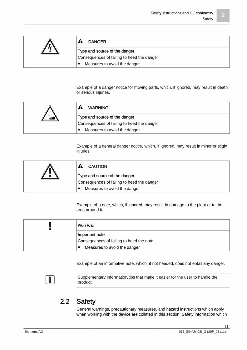
2.1 Typographical conventionsThe safety instructions in this document contain the following elements:l Symbol to indicate the nature of the dangerl Signal word to indicate the severity of the dangerl Type and source of the dangerl Consequences of failing to heed the dangerl Measures to avoid the danger
Symbols to indicate the nature of the dangerThe following symbols are used in the document:
Symbol Meaning
Warning of dangerous voltages
Warning of moving parts
General warning
Signal word to indicate the severity of the dangerThe severity of the danger is indicated using signal words (in accordance withANSI Z535).The following signal words are used in this document:
Signal word Severity of the danger
DANGER! Characterizes an immediate danger.If the danger is ignored, death or serious injuries will result.
WARNING! Characterizes a possible danger.If the danger is ignored, death or serious injuries may result.
CAUTION! Characterizes a possible danger.If the danger is ignored, minor or slight injuries may result.
NOTE! Characterizes a possible hazardous situation.If this is ignored, damage may occur to the plant or to the area around it.
Representation examples for safety instructions in this documentExample of a danger notice for hazardous voltages, which, if ignored, will result indeath or serious injuries.
Safety instructions and CE conformity 2Safety
11Siemens AG 016_SINAMICS_G120P_J5111en
DANGER
Type and source of the dangerConsequences of failing to heed the danger Measures to avoid the danger
Example of a danger notice for moving parts, which, if ignored, may result in deathor serious injuries.
WARNING
Type and source of the dangerConsequences of failing to heed the danger Measures to avoid the danger
Example of a general danger notice, which, if ignored, may result in minor or slightinjuries.
CAUTION
Type and source of the dangerConsequences of failing to heed the danger Measures to avoid the danger
Example of a note, which, if ignored, may result in damage to the plant or to thearea around it.
NOTICE
Important noteConsequences of failing to heed the note Measures to avoid the danger
Example of an informative note, which, if not heeded, does not entail any danger.
Supplementary information/tips that make it easier for the user to handle theproduct.
2.2 SafetyGeneral warnings, precautionary measures, and hazard instructions which applywhen working with the device are collated in this section. Safety information which

2 Safety instructions and CE conformitySafety
12Siemens AG 016_SINAMICS_G120P_J5111en
only applies to certain tasks is listed at the start of every section or is repeated oradded at critical points within these sections.
1. Please read this information carefully.
2. Pay attention to all the warning signs which are affixed to the equipment. Thewarning labels must always be legible. Missing or damaged labels must bereplaced.
DANGER
The device conducts hazardous voltagesThe capacitors and the line and motor terminals may conduct hazardous voltageseven when the device is not in service and is disconnected from the lineElectric shocks and short-circuits may occur if personnel come into contact withlive parts, spill liquids on them, or touch them with objects. Avoid any contact with live parts, spilling liquids on them, or touching them
with objects. After switching off the power supply, wait at least 5 minutes before opening
the device. Take additional external measures if there is a risk of short-circuits; for
example, independent limit switches or mechanical interlocks, etc.
WARNING
The device controls rotating mechanical partsContact with them can cause severe physical injuries and serious materialdamage. Only touch those parts in a stopped state. Certain parameter settings can cause the variable speed drive to restart
automatically after a fault, or after a failure in the supply voltage once the faultis eliminated and acknowledged, or after the power supply is restored.
Ensure that the DIP switches are correctly set, and that the inputs areproperly configured. Otherwise, the drive can start inadvertently.

Safety instructions and CE conformity 2Safety
13Siemens AG 016_SINAMICS_G120P_J5111en
WARNING
The devices may only be installed, commissioned, and maintained by trainedpersonnel.Many dangers, some potentially fatal, are posed by permitting unqualifiedpersonnel to work on the device. They may also result in damage to the deviceand to the plant.
w Qualified personnel are specialists who possess the skills required to install,mount, commission, operate, and repair the devices. These people must havethe following qualifications:
They must have received training and be authorized to switch the variablespeed drives on and off, to ground the devices in accordance with safetystandards, and to tag the circuits. They are generally people with expertise inthe area of electrical installation or people who work under the supervision ofexperts, such as qualified electricians.
They have to be familiar with all the safety information, installation andoperating instructions contained in this guide, and be trained to perform firstaid.
CAUTION
It is only permissible to use the device for the purposes specified by themanufacturer.Unauthorized use or modifications can result in fires, electric shocks, and injuries. The device may only be used for the intended purpose. Do not carry out any modifications to the device. Only use spare parts and accessories which are distributed or recommended
by the manufacturer of the device. Do not use the device as an "emergency stop device" (see EN 60204,
9.2.5.4).
NOTICE
The required ambient conditions must be observed.Unsuitable ambient conditions can affect the functions of the device. Only install the variable speed drive in areas which are free from jolts,
vibrations, electromagnetic fields, and corrosive gases. Maintain the ambient conditions which are specified in the technical data,
such as temperature, pressure, humidity, etc.
2 Safety instructions and CE conformityDisclaimer of liability
14Siemens AG 016_SINAMICS_G120P_J5111en
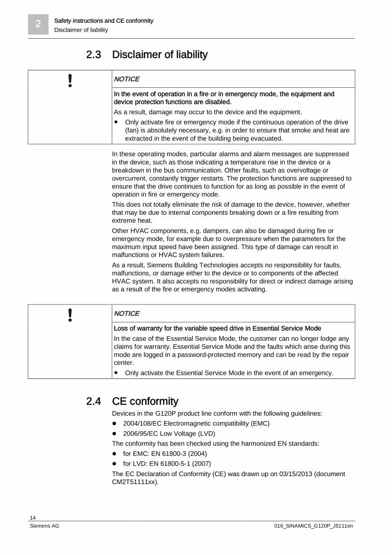
2.3 Disclaimer of liability
NOTICE
In the event of operation in a fire or in emergency mode, the equipment anddevice protection functions are disabled.As a result, damage may occur to the device and the equipment. Only activate fire or emergency mode if the continuous operation of the drive
(fan) is absolutely necessary, e.g. in order to ensure that smoke and heat areextracted in the event of the building being evacuated.
In these operating modes, particular alarms and alarm messages are suppressedin the device, such as those indicating a temperature rise in the device or abreakdown in the bus communication. Other faults, such as overvoltage orovercurrent, constantly trigger restarts. The protection functions are suppressed toensure that the drive continues to function for as long as possible in the event ofoperation in fire or emergency mode.This does not totally eliminate the risk of damage to the device, however, whetherthat may be due to internal components breaking down or a fire resulting fromextreme heat.Other HVAC components, e.g. dampers, can also be damaged during fire oremergency mode, for example due to overpressure when the parameters for themaximum input speed have been assigned. This type of damage can result inmalfunctions or HVAC system failures.As a result, Siemens Building Technologies accepts no responsibility for faults,malfunctions, or damage either to the device or to components of the affectedHVAC system. It also accepts no responsibility for direct or indirect damage arisingas a result of the fire or emergency modes activating.
NOTICE
Loss of warranty for the variable speed drive in Essential Service ModeIn the case of the Essential Service Mode, the customer can no longer lodge anyclaims for warranty. Essential Service Mode and the faults which arise during thismode are logged in a password-protected memory and can be read by the repaircenter. Only activate the Essential Service Mode in the event of an emergency.
2.4 CE conformityDevices in the G120P product line conform with the following guidelines:l 2004/108/EC Electromagnetic compatibility (EMC)l 2006/95/EC Low Voltage (LVD)The conformity has been checked using the harmonized EN standards:l for EMC: EN 61800-3 (2004)l for LVD: EN 61800-5-1 (2007)The EC Declaration of Conformity (CE) was drawn up on 03/15/2013 (documentCM2T51111xx).

Environment 3Notes on environmental compatibility and disposal
15Siemens AG 016_SINAMICS_G120P_J5111en
3 Environment
3.1 Notes on environmental compatibility and disposalNote the following information when disposing of the device:
This device has been developed and manufactured using environmentally friendlymaterials and processes. It also conforms to Siemens environmental standards.
Do not dispose of this device along with household waste. This is particularly relevant inthe case of assembled printed-circuit boards.From an environmental perspective, it makes sense to treat specialized components in aparticular way. In some circumstances, this is even a legal requirement. Please observelocal regulations and the applicable laws in force.
Make use of local collection points and disposal companies, or contact yoursupplier/manufacturer to find out whether they will take back your device or providefurther information on environmental compatibility and disposal.
Environmental compatibility:Siemens makes every effort to manufacture products in accordance with RoHSconformity RL 2011/65/EU (RoHS).

4 Basic technical principlesDescriptions of functions
16Siemens AG 016_SINAMICS_G120P_J5111en
4 Basic technical principles
4.1 Descriptions of functions
4.1.1 Variable speed drives
4.1.1.1 What is a variable speed drive?In the past, AC and three-phase motors could only operate at a constant speed.This speed was determined solely by the frequency of the power supply (50 or60 Hz) and the number of the motor's pole pairs.Thanks to advances in the field of power electronics, compact devices known asvariable speed drives have been developed which can convert the fixed frequencyof the power supply into virtually any other frequency.
EM
VFi
lter
Motor
5192Z51_02
Linesupply
Filter Rectifier DC linkcapacitor
Inverter Motor
The variable speed drive transforms the AC line voltage (50 or 60 Hz) into avariable output voltage with variable frequency by means of a rectifier and aninverter. This output frequency can be greater than the line frequency.Once connected, this is how a motor alters its speed depending on the frequencyand the associated output voltage, and so the speed can be varied as needed.
4.1.1.2 Operating principle of a variable speed drive51
92Z5
2en_
02
Powersupply
Rectifer DC link capacifer Inverter
Block diagram
Basic technical principles 4Descriptions of functions
17Siemens AG 016_SINAMICS_G120P_J5111en
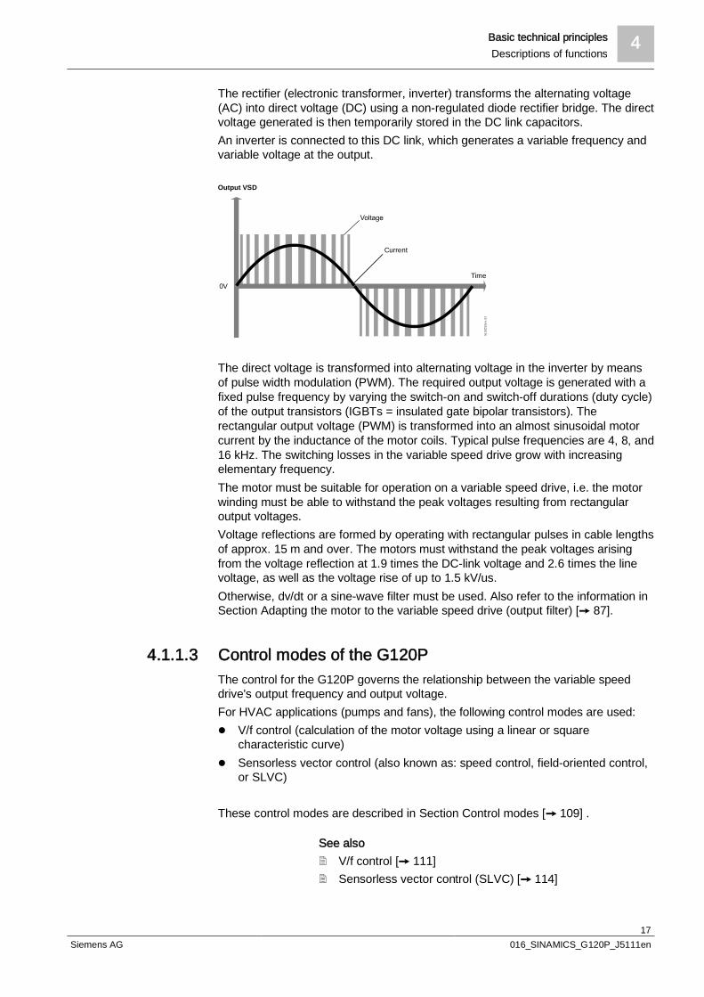
The rectifier (electronic transformer, inverter) transforms the alternating voltage(AC) into direct voltage (DC) using a non-regulated diode rectifier bridge. The directvoltage generated is then temporarily stored in the DC link capacitors.An inverter is connected to this DC link, which generates a variable frequency andvariable voltage at the output.
0V
Output VSD
Current
Time
5192
Z53
en_0
2
The direct voltage is transformed into alternating voltage in the inverter by meansof pulse width modulation (PWM). The required output voltage is generated with afixed pulse frequency by varying the switch-on and switch-off durations (duty cycle)of the output transistors (IGBTs = insulated gate bipolar transistors). Therectangular output voltage (PWM) is transformed into an almost sinusoidal motorcurrent by the inductance of the motor coils. Typical pulse frequencies are 4, 8, and16 kHz. The switching losses in the variable speed drive grow with increasingelementary frequency.The motor must be suitable for operation on a variable speed drive, i.e. the motorwinding must be able to withstand the peak voltages resulting from rectangularoutput voltages.Voltage reflections are formed by operating with rectangular pulses in cable lengthsof approx. 15 m and over. The motors must withstand the peak voltages arisingfrom the voltage reflection at 1.9 times the DC-link voltage and 2.6 times the linevoltage, as well as the voltage rise of up to 1.5 kV/us.Otherwise, dv/dt or a sine-wave filter must be used. Also refer to the information inSection Adapting the motor to the variable speed drive (output filter) [ 87].
4.1.1.3 Control modes of the G120PThe control for the G120P governs the relationship between the variable speeddrive's output frequency and output voltage.For HVAC applications (pumps and fans), the following control modes are used:l V/f control (calculation of the motor voltage using a linear or square
characteristic curve)l Sensorless vector control (also known as: speed control, field-oriented control,
or SLVC)
These control modes are described in Section Control modes [ 109] .
See also2 V/f control [ 111]2 Sensorless vector control (SLVC) [ 114]
4 Basic technical principlesDescriptions of functions
18Siemens AG 016_SINAMICS_G120P_J5111en
4.1.1.4 Advantages of a variable speed driveUsing electronic speed controllers in HVAC systems (pumps, fans, compressors)not only allows you to save energy, it also reduces system operating costs.The more often a system operates within the partial load range, the greater thesavings, and the investment in a speed controller pays for itself in just a fewmonths.As the systems are usually designed for full load, partial load operation is thepredominant operating mode.
The speed is set to the actual required value, for example, by the flow, volumeflow, pressure, or differential pressure. This allows the system to operate at theoptimal operating point and achieve the best possible efficiency.Adapting to the required speed is a very quick process, meaning the requiredvolume flow or flow is available immediately.
The soft starting and braking of the controlled motors (definable ramp up and rampdown time) reduces wear to the motor and system components as there are noabrupt pressure variations when switching on and off. The benefits of this can beseen in the form of lower maintenance costs and a longer system service life, andas a result, the total costs over the entire service life of the system are reduced.The variable speed drive also protects the motor against overcurrent andoverloading, which increases its service life further still.It is possible to reduce the load on the system caused by mechanical resonances(e.g. in compressors) by skipping critical speed ranges.
Lower speeds mean lower noise emissions. The noises transferred by pipelinesand channels cause less disruption.
Using a variable speed drive allows the following mechanical and electricalcomponents for a conventional control to be left out. As a result, the initial outlay fora variable speed drive has often already been covered.l Mechanical reactors and valves for controlling the flow, volume flow, or
pressurel Motor circuit breakers and thermal overload relays are only required in bypass
applications or where several motors are used in parallel with a G120Pl On/off switch and relayl Star-delta (wye-delta) starter (Y/∆) or soft starterl Y/∆ startup requires 2 cables between motor circuit breaker and motor; the
G120P only requires onel Y/∆ startup requires 3 power contactors; the G120P requires nonel Time relaysl Operating hours counters and ammeters for the motor status are integrated
into the variable speed drivel Reactive current compensation can be reduced
Thanks to its many additional specific functions, the G120P is ideal for use inHVAC applications:l Integrated PID controller for controlling the input speed depending on the
pressure, temperature, flow, fill level, air quality, or other process variables, aswell as 3 supplementary PID controllers for controlling additional HVAC systemcomponents such as dampers or valve actuators
l Multi-zone controllerl Pump cascade for up to 4 pumps
Energy saving
Operating pointoptimization
Smooth operation
Noise reduction
Fewer systemcomponents required
Large integrated range offunctions

Basic technical principles 4Descriptions of functions
19Siemens AG 016_SINAMICS_G120P_J5111en
l Hibernation mode (energy-saving mode)l 2 operating modes: Comfort mode and fire mode (e.g. overpressure ventilation)l Bypass function for high availabilityl V-belt monitoring without external sensorl Many digital and analog inputs and outputs incl. direct inputs for LG-Ni1000
and Pt1000 temperature sensorsl Programmable time switches (x 3 units)l Real-time clock for time-dependent process controls, e.g. temperature
reduction for heating control at nightl Freely programmable logical function blocks for simulating simple PLC
functions
l Significant reduction of harmonics (LHT = low harmonic technology), whichimproves the power factor (true power factor)
l Space-saving design of G120Ps with degree of protection IP20 in booksizeformat means they can be installed directly alongside each other
l G120Ps with degree of protection IP55 in frame sizes D to F do not require anadditional rear panel for stand-alone installation. For frame sizes A to C, a rearpanel can be ordered as an external accessory.
l One operator panel for all performance rangesl Numerical operator panel with upload and download function and memory for
one parameter setl Plain text operator panel with upload and download function and memory for up
to 16 parameter setsl Possible to upload and download parameter settings using the operator panel
without a tool, even for devices with degree of protection IP55l MMC/SD memory card slot for backup, upload, and download functions, and
memory for 100 parameter setsl Possible to upgrade the firmware to the latest version using an MMC/SD card
(for all devices from firmware version 4.6 and later)
l All key feedback signals for setting the control loop appear on the displayl The appropriate information is provided immediately in the event of a faultl Commissioning takes just a few minutesl Direction of rotation can be easily reversed using parameters in the event of an
incorrect phase sequencel Volume flow or pressure can be set with ease by changing the motor speed
between minimum and maximum speedl No V-belt settings required to achieve the necessary pressure and/or volume
flowl Commissioning takes place via a Windows computer with graphical, intuitive
operating software
The simple connection to Siemens building automation systems means that drivenpumps and fans within the building management systems can be monitored withease and ideally controlled using the G120P.
Key operating parameters such as output frequency, output current, output voltage,output power, and errors can be read.
Cosφ can only be used as a power factor for sinusoidal oscillations. As variablespeed drives do not generate perfect sine waves, the real power factor (ratiobetween kW load and kVA load) is used instead of cosφ.
Other key features:
Simple installation andfast commissioning
Simple connection tobuilding automationsystem
Display for all relevantoperating data
Real power factor

4 Basic technical principlesDescriptions of functions
20Siemens AG 016_SINAMICS_G120P_J5111en
The G120P uses low harmonic technology (LHT), so the typical power factor isusually between 0.92 and 0.96 depending on the characteristics of the line supply.
The starting current of an induction motor is 6 to 10 times the rated current. A star-delta (wye-delta) switch reduces this value to twice the rated current.During basic commissioning/motor identification, the G120P calculates the requiredmaximum current (approx. 150% of the rated current for the motor). The settingcan then be modified manually.When switching on, the current consumption is restricted to the set value, whichleads to a reduction in voltage supply deviations and, as a result, more stablepower supply conditions in the building.
4.1.2 AC motors
4.1.2.1 Asynchronous motors
l Also known as three-phase induction motorsl Simple and rugged designl Inexpensive and reliablel Most widely used type of motorl Suitable for direct mains connection or using a variable speed
drive/soft starterl Induction motors are primarily used for HVAC applications
(pumps and fans)
The G120P is designed for use with induction motors. If your project involvescontrolling synchronous motors, please contact your local Siemens branch officefor the best possible advice.
Peaks in current arereduced
Basic technical principles 4Descriptions of functions
21Siemens AG 016_SINAMICS_G120P_J5111en
4.1.2.2 Components of an AC motor
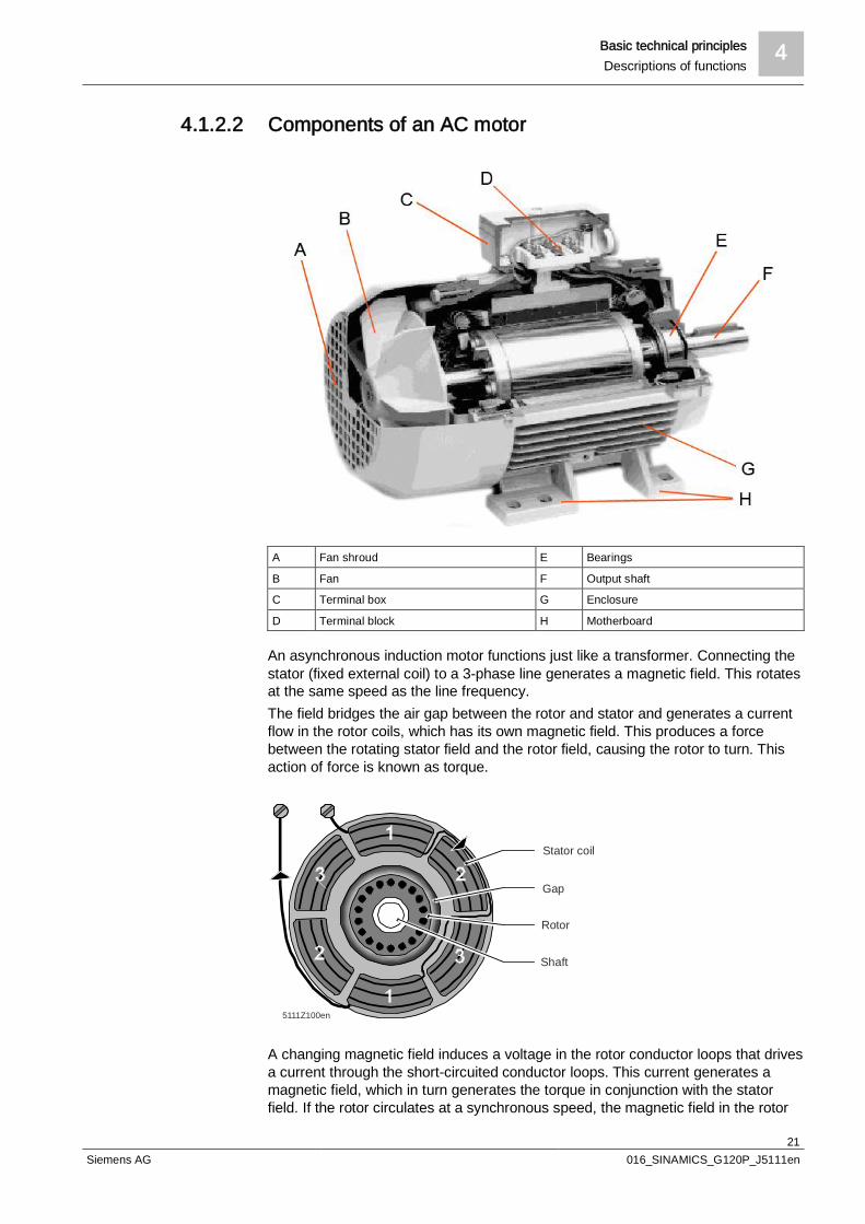
A Fan shroud E Bearings
B Fan F Output shaft
C Terminal box G Enclosure
D Terminal block H Motherboard
An asynchronous induction motor functions just like a transformer. Connecting thestator (fixed external coil) to a 3-phase line generates a magnetic field. This rotatesat the same speed as the line frequency.The field bridges the air gap between the rotor and stator and generates a currentflow in the rotor coils, which has its own magnetic field. This produces a forcebetween the rotating stator field and the rotor field, causing the rotor to turn. Thisaction of force is known as torque.
Rotor
Shaft
5111Z100en
Gap
Stator coil
A changing magnetic field induces a voltage in the rotor conductor loops that drivesa current through the short-circuited conductor loops. This current generates amagnetic field, which in turn generates the torque in conjunction with the statorfield. If the rotor circulates at a synchronous speed, the magnetic field in the rotor

4 Basic technical principlesDescriptions of functions
22Siemens AG 016_SINAMICS_G120P_J5111en
conductor loops does not change, no voltage is induced, and, as a result, notorque is applied either.To generate torque, currents have to be induced in the rotor. This is why the motoralways runs at a slower pace than the rotating field. This difference in speed isknown as slip, and is typically 3% at 15 kW.If the coils are arranged in several pairs (or poles), the frequency of the rotatingfield is lower than the applied frequency:l For 2 poles and 50/60 Hz = a speed of 3,000/3,600 per minutel For 4 poles and 50/60 Hz = a speed of 1,500/1,800 per minute
5111D133en
Max. torque(Breakdown torque)
Normal operating point(Nominal torque)
Variable speed mode
Torque
SpeedSlip
The speed of a motor depends on the frequency, coil arrangement, and load.To control the motor speed, you must also control the frequency of the powersupply.
If the frequency is reduced, the voltage should also be reduced, otherwise thestator current and magnetic flux will be too high and cause the magnetic motor fieldto become saturated. For this reason, the voltage must also be controlled andreduced. If the frequency is increased above the normal value (line frequency), ahigher voltage is required to achieve the maximum flux. As this is not generallypossible, a lower torque is available at higher speeds (for example at speedsabove the line frequency = field weakening mode). Also refer to the information inthe Section on Operating motors at higher frequencies [ 47].
0 0.5 1.0 1.2 1.5
Flux Voltage
Torque
Speed (X 50/50)
Torque
5192d12en_02
4.1.2.3 Electric motor parameters
Typical parameters Starting current: 600...1000 %Starting torque: 225 %
Parameters

Basic technical principles 4Descriptions of functions
23Siemens AG 016_SINAMICS_G120P_J5111en
5192D13en_02
Current
Torque
Normaleroperating point
Motor speed (4-pole motor) rpm
Depending on the motor, the starting currentis roughly 6 to 10 times greater than therated current. Particularly in larger motors,this can cause problems (sizes of upstreamfuses, unwanted network loads, etc.).
Speed depending on the number of poles Rated speed = (variable speed drivefrequency - slip frequency) * 60 / number ofpole pairs
l 2-pole motor = approx. 2,910 rpm at50 Hz
l 4-pole motor = approx. 1,455 rpm at50 Hz
l 8-pole motor = approx. 727 rpm at50 Hz
The speed is proportional to the frequencywith a constant number of pole pairs.
A motor's rating plate contains a lot ofinformation. We are only interested in themost important details, i.e. the informationrelating to motor operation and itsapplications.
Voltage Voltage for which the motor was designedand with which it operates at the ratedtorque.A distinction is made between star and deltavoltage. This is depicted on the rating platewith the symbols Y (star) and ∆ (delta):l In the example rating plate: 690 V for Yl In the example rating plate: 400 V for ∆
Frequency Frequency for which the motor wasdesigned and with which it operates at therated voltage:l In Europe, this is 50 Hzl In the USA, this is 60 Hz
Rated current Current required by the motor to deliver therated power in accordance with the ratingplate. A distinction is made between Y (star)and ∆ (delta):l In the example rating plate: 24 A for Yl In the example rating plate: 40.5 A for ∆
Rated power The motor's output power as specified onthe motor rating plate:l In the example rating plate: 22 kW
Power factor (cos φ) Reactive power of a motor at rated power:l In the example rating plate: 0.84
rpm Revolutions per minute. Rated speed of theoutput shaft in revolutions per minute at a
Rating plate

4 Basic technical principlesDescriptions of functions
24Siemens AG 016_SINAMICS_G120P_J5111en
line frequency of 50 or 60 Hz:l In the example rating plate: 1,470 rpml In the example rating plate: 1,775 rpm
NOTICE
Motors that are not suitable for use with variable speed drivesThe motor must be suitable for use with variable speed drives, otherwise damagemay occur during operation, for example to the motor winding. Consult the motor manufacturer to find out whether the motor is suitable for
direct variable speed drive operation.
4.1.2.4 Star and delta connectionDepending on the application, you can operate the motor in the star or deltaconnection (Y/Δ). The line voltage and connection type can be found on themotor's rating plate, for example 230/400 V Δ/Y.
l Ensure the interconnection is correct before connecting the motor.
Delta connection/Star connection
U W
W UW U
WU
Motor terminal board
5192
Z30e
n
Smaller motors (230/400 VAC Δ/Y) generally have a star connection, while largermotors (400/690 VAC Δ/Y) generally have a delta connection. The requiredconnection is also dependent on the planned frequency range during operation.
A motor is normally operated between standstill and its rated speed, i.e. a speedcorresponding to the line frequency. In this case the motor must be connected in Y,or in Δ if this is specified by the rating plate In this case, it is only possible tooperate the motor above its rated speed with field weakening, i.e. the availabletorque for the motor is reduced above the rated speed.
Operation with the "87 Hz characteristic" is only possible with 230/400 VAC Δ/Ymotors. You also need to connect the motor in Δ. With the "87 Hz characteristic",the motor's power output increases. Also refer to the information in SectionOperating motors at higher frequencies [ 47].
Operation up to the ratedspeed
Operation with "87 Hzcharacteristic"
Planning 5Variable speed drive selection
25Siemens AG 016_SINAMICS_G120P_J5111en
5 Planning
5.1 Variable speed drive selection
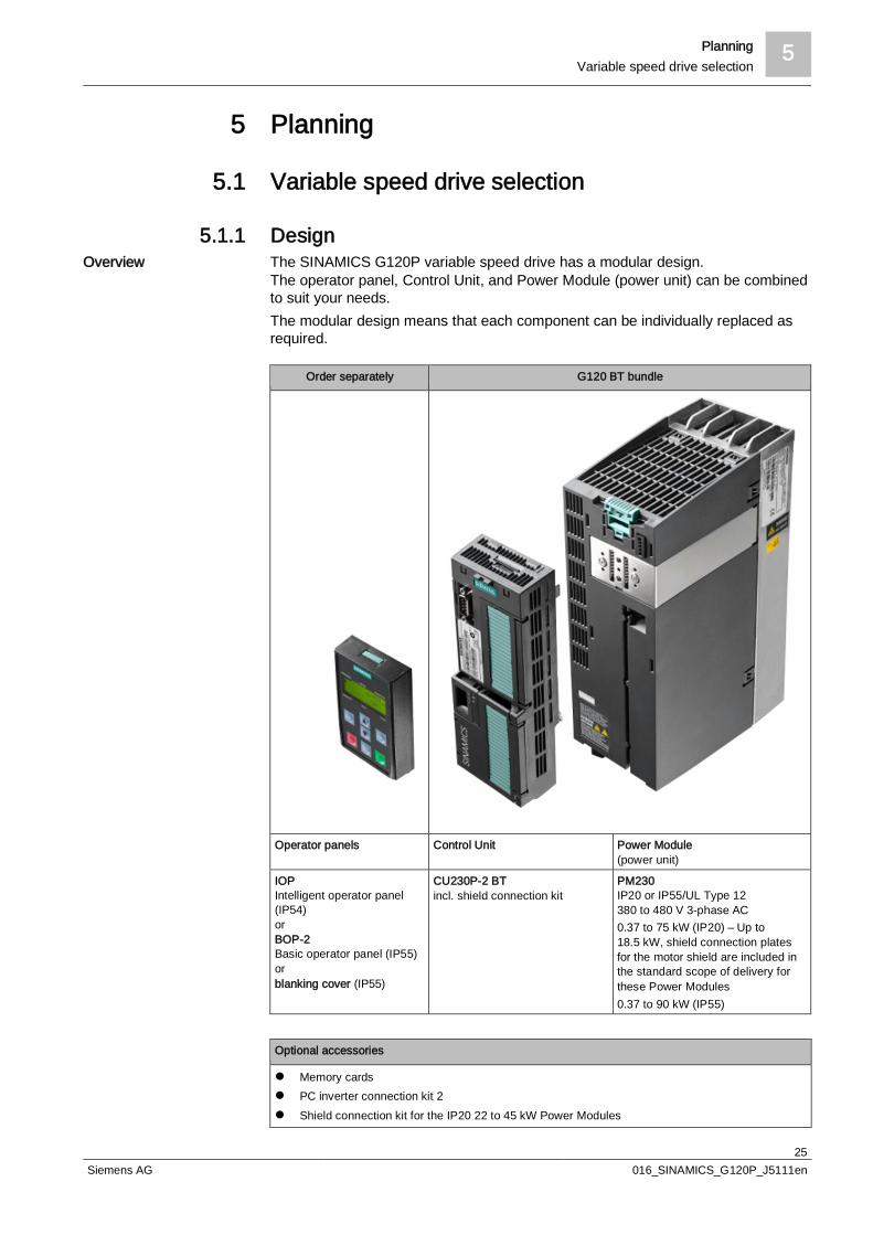
5.1.1 DesignThe SINAMICS G120P variable speed drive has a modular design.The operator panel, Control Unit, and Power Module (power unit) can be combinedto suit your needs.The modular design means that each component can be individually replaced asrequired.
Order separately G120 BT bundle
Operator panels Control Unit Power Module(power unit)
IOPIntelligent operator panel(IP54)orBOP-2Basic operator panel (IP55)orblanking cover (IP55)
CU230P-2 BTincl. shield connection kit
PM230IP20 or IP55/UL Type 12380 to 480 V 3-phase AC0.37 to 75 kW (IP20) – Up to18.5 kW, shield connection platesfor the motor shield are included inthe standard scope of delivery forthese Power Modules0.37 to 90 kW (IP55)
Optional accessories
l Memory cardsl PC inverter connection kit 2l Shield connection kit for the IP20 22 to 45 kW Power Modules
Overview
5 PlanningVariable speed drive selection
26Siemens AG 016_SINAMICS_G120P_J5111en
Optional accessories
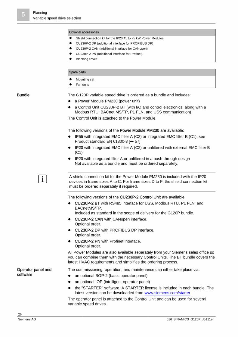
l Shield connection kit for the IP20 45 to 75 kW Power Modulesl CU230P-2 DP (additional interface for PROFIBUS DP)l CU230P-2 CAN (additional interface for CANopen)l CU230P-2 PN (additional interface for Profinet)l Blanking cover
Spare parts
l Mounting setl Fan units
The G120P variable speed drive is ordered as a bundle and includes:l a Power Module PM230 (power unit)l a Control Unit CU230P-2 BT (with I/O and control electronics, along with a
Modbus RTU, BACnet MS/TP, P1 FLN, and USS communication)The Control Unit is attached to the Power Module.
The following versions of the Power Module PM230 are available:l IP55 with integrated EMC filter A (C2) or integrated EMC filter B (C1), see
Product standard EN 61800-3 [ 57]l IP20 with integrated EMC filter A (C2) or unfiltered with external EMC filter B
(C1)l IP20 with integrated filter A or unfiltered in a push-through design
Not available as a bundle and must be ordered separately.
A shield connection kit for the Power Module PM230 is included with the IP20devices in frame sizes A to C. For frame sizes D to F, the shield connection kitmust be ordered separately if required.
The following versions of the CU230P-2 Control Unit are available:l CU230P-2 BT with RS485 interface for USS, Modbus RTU, P1 FLN, and
BACnetMS/TP.Included as standard in the scope of delivery for the G120P bundle.
l CU230P-2 CAN with CANopen interface.Optional order.
l CU230P-2 DP with PROFIBUS DP interface.Optional order.
l CU230P-2 PN with Profinet interface.Optional order.
All Power Modules are also available separately from your Siemens sales office soyou can combine them with the necessary Control Units. The BT bundle covers thelatest HVAC requirements and simplifies the ordering process.
The commissioning, operation, and maintenance can either take place via:l an optional BOP-2 (basic operator panel)l an optional IOP (intelligent operator panel)l the "STARTER" software. A STARTER license is included in each bundle. The
latest version can be downloaded from www.siemens.com/starterThe operator panel is attached to the Control Unit and can be used for severalvariable speed drives.
Bundle
Operator panel andsoftware

Planning 5Variable speed drive selection
27Siemens AG 016_SINAMICS_G120P_J5111en
The optional blanking cover allows you to protect the connections with a remoteoperator panel. The high degree of protection (IP55) is only achieved with theblanking cover or the BOP-2.
5.1.2 Type overview
G120P-a/bcd
G120P a b c d
Type Power [kW] Voltage range IP Filter
3 = 380 to 480 V 2 = 20 A = Class A filterB = Class B filter
3 = 380 to 480 V 5 = 55 A = Class A filterB = Class B filter
The type designation (ASN) G120P-7.5/35A defines a G120P variable speed drivefor a power of 7.5 kW [aaaa] in the voltage range 380 to 480 V [b], degree ofprotection IP55 [c], and filter class A [d].
The G120P is only supplied for the voltage range 380 to 480 V and with class Aor B filters. Unfiltered devices can also be supplied if required, although these arenot normally used in building management systems as they do not meet the EMCstandards.
The devices achieve degree of protection IP55 when a BOP-2 or blanking cover isused. Degree of protection IP54 is achieved with an IOP.
Order no./MLFB Type Filterclass
Framesize
Power (kW)at LO (lowoverload)
Outputcurrent (A)at LO (lowoverload)
Efficiency Power loss[kW]
6SL3200-6AM11-3AH0 G120P-0.37/35A A A 0.37 1.3 0.86 0.06
6SL3200-6AM11-7AH0 G120P-0.55/35A A A 0.55 1.7 0.90 0.06
6SL3200-6AM12-2AH0 G120P-0.75/35A A A 0.75 2.2 0.92 0.06
6SL3200-6AM13-1AH0 G120P-1.1/35A A A 1.1 3.1 0.94 0.07
6SL3200-6AM14-1AH0 G120P-1.5/35A A A 1.5 4.1 0.95 0.08
6SL3200-6AM15-8AH0 G120P-2.2/35A A A 2.2 5.9 0.96 0.1
6SL3200-6AM17-7AH0 G120P-3/35A A A 3 7.7 0.96 0.12
6SL3200-6AM21-0AH0 G120P-4/35A A B 4 10.2 0.97 0.14
6SL3200-6AM21-3AH0 G120P-5.5/35A A B 5.5 13.2 0.97 0.18
6SL3200-6AM21-8AH0 G120P-7.5/35A A B 7.5 18 0.97 0.24
6SL3200-6AM22-6AH0 G120P-11/35A A C 11 26 0.97 0.32
6SL3200-6AM23-2AH0 G120P-15/35A A C 15 32 0.97 0.39
6SL3200-6AM23-8AH0 G120P-18.5/35A A C 18.5 38 0.98 0.46
6SL3200-6AM24-5AH0 G120P-22/35A A D 22 45 0.97 0.52
6SL3200-6AM26-0AH0 G120P-30/35A A D 30 60 0.97 0.68
6SL3200-6AM27-5AH0 G120P-37/35A A E 37 75 0.97 0.99
6SL3200-6AM28-8AH0 G120P-45/35A A E 45 90 0.97 1.2
Type code
Example
Type code for G120Pbundle IP55

5 PlanningVariable speed drive selection
28Siemens AG 016_SINAMICS_G120P_J5111en
6SL3200-6AM31-1AH0 G120P-55/35A A F 55 110 0.97 1.4
6SL3200-6AM31-4AH0 G120P-75/35A A F 75 145 0.97 1.9
6SL3200-6AM31-7AH0 G120P-90/35A A F 90 178 0.97 2.3
6SL3200-6AM11-3BH0 G120P-0.37/35B B A 0.37 1.3 0.86 0.06
6SL3200-6AM11-7BH0 G120P-0.55/35B B A 0.55 1.7 0.90 0.06
6SL3200-6AM12-2BH0 G120P-0.75/35B B A 0.75 2.2 0.92 0.06
6SL3200-6AM13-1BH0 G120P-1.1/35B B A 1.1 3.1 0.94 0.07
6SL3200-6AM14-1BH0 G120P-1.5/35B B A 1.5 4.1 0.95 0.08
6SL3200-6AM15-8BH0 G120P-2.2/35B B A 2.2 5.9 0.96 0.1
6SL3200-6AM17-7BH0 G120P-3/35B B A 3 7.7 0.96 0.12
6SL3200-6AM21-0BH0 G120P-4/35B B B 4 10.2 0.97 0.14
6SL3200-6AM21-3BH0 G120P-5.5/35B B B 5.5 13.2 0.97 0.18
6SL3200-6AM21-8BH0 G120P-7.5/35B B B 7.5 18 0.97 0.24
6SL3200-6AM22-6BH0 G120P-11/35B B C 11 26 0.97 0.32
6SL3200-6AM23-2BH0 G120P-15/35B B C 15 32 0.97 0.39
6SL3200-6AM23-8BH0 G120P-18.5/35B B D 18.5 38 0.97 0.52
6SL3200-6AM24-5BH0 G120P-22/35B B D 22 45 0.97 0.52
6SL3200-6AM26-0BH0 G120P-30/35B B D 30 60 0.97 0.68
6SL3200-6AM27-5BH0 G120P-37/35B B E 37 75 0.97 0.99
6SL3200-6AM28-8BH0 G120P-45/35B B E 45 90 0.97 1.2
6SL3200-6AM31-1BH0 G120P-55/35B B F 55 110 0.97 1.4
6SL3200-6AM31-4BH0 G120P-75/35B B F 75 145 0.97 1.9
6SL3200-6AM31-7BH0 G120P-90/35B B F 90 178 0.97 2.3
Order no./MLFB Type Filterclass
Framesize
Power (kW)at LO (lowoverload)
Outputcurrent (A)at LO (lowoverload)
Efficiency Power loss[kW]
6SL3200-6AE11-3AH0 G120P-0.37/32A A A 0.37 1.3 0.86 0.06
6SL3200-6AE11-7AH0 G120P-0.55/32A A A 0.55 1.7 0.90 0.06
6SL3200-6AE12-2AH0 G120P-0.75/32A A A 0.75 2.2 0.92 0.06
6SL3200-6AE13-1AH0 G120P-1.1/32A A A 1.1 3.1 0.94 0.07
6SL3200-6AE14-1AH0 G120P-1.5/32A A A 1.5 4.1 0.95 0.08
6SL3200-6AE15-8AH0 G120P-2.2/32A A A 2.2 5.9 0.96 0.1
6SL3200-6AE17-7AH0 G120P-3/32A A A 3 7.7 0.96 0.12
6SL3200-6AE21-0AH0 G120P-4/32A A B 4 10.2 0.97 0.14
6SL3200-6AE21-3AH0 G120P-5.5/32A A B 5.5 13.2 0.97 0.18
6SL3200-6AE21-8AH0 G120P-7.5/32A A B 7.5 18 0.97 0.24
6SL3200-6AE22-6AH0 G120P-11/32A A C 11 26 0.97 0.32
6SL3200-6AE23-2AH0 G120P-15/32A A C 15 32 0.97 0.39
6SL3200-6AE23-8AH0 G120P-18.5/32A A C 18.5 38 0.98 0.46
6SL3200-6AE24-5AH0 G120P-22/32A A D 22 45 0.97 0.52
Type code for G120Pbundle IP20
Planning 5Variable speed drive selection
29Siemens AG 016_SINAMICS_G120P_J5111en
6SL3200-6AE26-0AH0 G120P-30/32A A D 30 60 0.97 0.68
6SL3200-6AE27-5AH0 G120P-37/32A A E 37 75 0.97 0.99
6SL3200-6AE28-8AH0 G120P-45/32A A E 45 90 0.97 1.2
6SL3200-6AE31-1AH0 G120P-55/32A A F 55 110 0.97 1.4
6SL3200-6AE31-4AH0 G120P-75/32A A F 75 145 0.97 1.9
6SL3200-6AE11-3BH0 G120P-0.37/32B B A 0.37 1.3 0.97 0.06
6SL3200-6AE11-7BH0 G120P-0.55/32B B A 0.55 1.7 0.86 0.06
6SL3200-6AE12-2BH0 G120P-0.75/32B B A 0.75 2.2 0.90 0.06
6SL3200-6AE13-1BH0 G120P-1.1/32B B A 1.1 3.1 0.92 0.07
6SL3200-6AE14-1BH0 G120P-1.5/32B B A 1.5 4.1 0.94 0.08
6SL3200-6AE15-8BH0 G120P-2.2/32B B A 2.2 5.9 0.95 0.1
6SL3200-6AE17-7BH0 G120P-3/32B B A 3 7.7 0.96 0.12
6SL3200-6AE21-0BH0 G120P-4/32B B B 4 10.2 0.96 0.14
6SL3200-6AE21-3BH0 G120P-5.5/32B B B 5.5 13.2 0.97 0.18
6SL3200-6AE21-8BH0 G120P-7.5/32B B B 7.5 18 0.97 0.24
6SL3200-6AE22-6BH0 G120P-11/32B B C 11 26 0.97 0.32
6SL3200-6AE23-2BH0 G120P-15/32B B C 15 32 0.97 0.39
6SL3200-6AE23-8BH0 G120P-18.5/32B B C 18.5 38 0.97 0.52
6SL3200-6AE24-5BH0 G120P-22/32B B D 22 45 0.97 0.52
6SL3200-6AE26-0BH0 G120P-30/32B B D 30 60 0.97 0.68
6SL3200-6AE27-5BH0 G120P-37/32B B E 37 75 0.97 0.99
6SL3200-6AE28-8BH0 G120P-45/32B B E 45 90 0.97 1.2
6SL3200-6AE31-1BH0 G120P-55/32B B F 55 110 0.97 1.4
6SL3200-6AE31-4BH0 G120P-75/32B B F 75 145 0.97 1.9
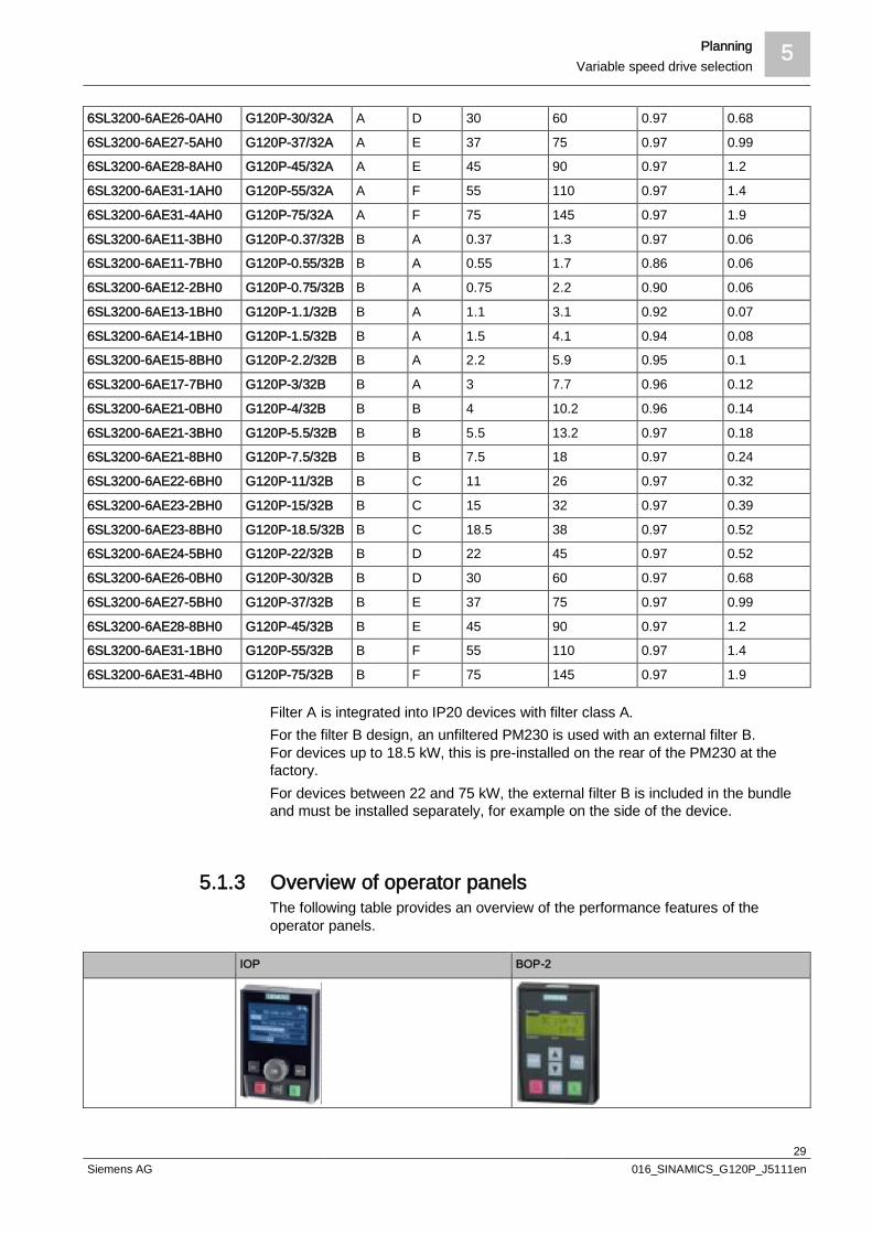
Filter A is integrated into IP20 devices with filter class A.For the filter B design, an unfiltered PM230 is used with an external filter B.For devices up to 18.5 kW, this is pre-installed on the rear of the PM230 at thefactory.For devices between 22 and 75 kW, the external filter B is included in the bundleand must be installed separately, for example on the side of the device.
5.1.3 Overview of operator panelsThe following table provides an overview of the performance features of theoperator panels.
IOP BOP-2

5 PlanningVariable speed drive selection
30Siemens AG 016_SINAMICS_G120P_J5111en
IOP BOP-2
Operator panel l Large plain text displayl Menu-based operation and application wizards
l 7-segment displayl Menu navigation
Possible uses l Directly mounted on SINAMICS G120Pl IP54/UL Type 12 degree of protectionl 5 languages installed at the factory. More can
be downloaded from the Internet
l Directly mounted on SINAMICS G120Pl IP55/UL Type 12 degree of protection
Startup l Series commissioning via the clone function(max. 16 data records)
l User-defined parameter list with a reducednumber of self-selected parameters
l Simple commissioning of standardapplications using application-specific wizards,it is not necessary to know the parameterstructure
l Commissioning largely possible withoutdocumentation thanks to additionalexplanations via the info button
l Series commissioning via the clone function(1 data record)
Operation and GUI l Direct manual operation of the drivel Simple switchover between automatic and
manual operationl Intuitive navigation with rotary-knob controll Graphic display with trend functions for
representing status values such as pressureand flow rate, for example, in bar charts
l Status display with freely selectable units tospecify physical values
l Direct manual operation of the drivel Simple switchover between automatic and manual
operationl Two-line display for indicating up to 2 process
values with text
Minimal maintenanceperiods
l Diagnostics using plain text display, withoutdocumentation, and can be used locally on-site
l Simple update of languages, wizards, andfirmware via USB
l Language packs, operating system updates,and expansions available free athttp://support.automation.siemens.com/WW/view/en/30563514/130000
l Menu assisted diagnostics with 7-segment display
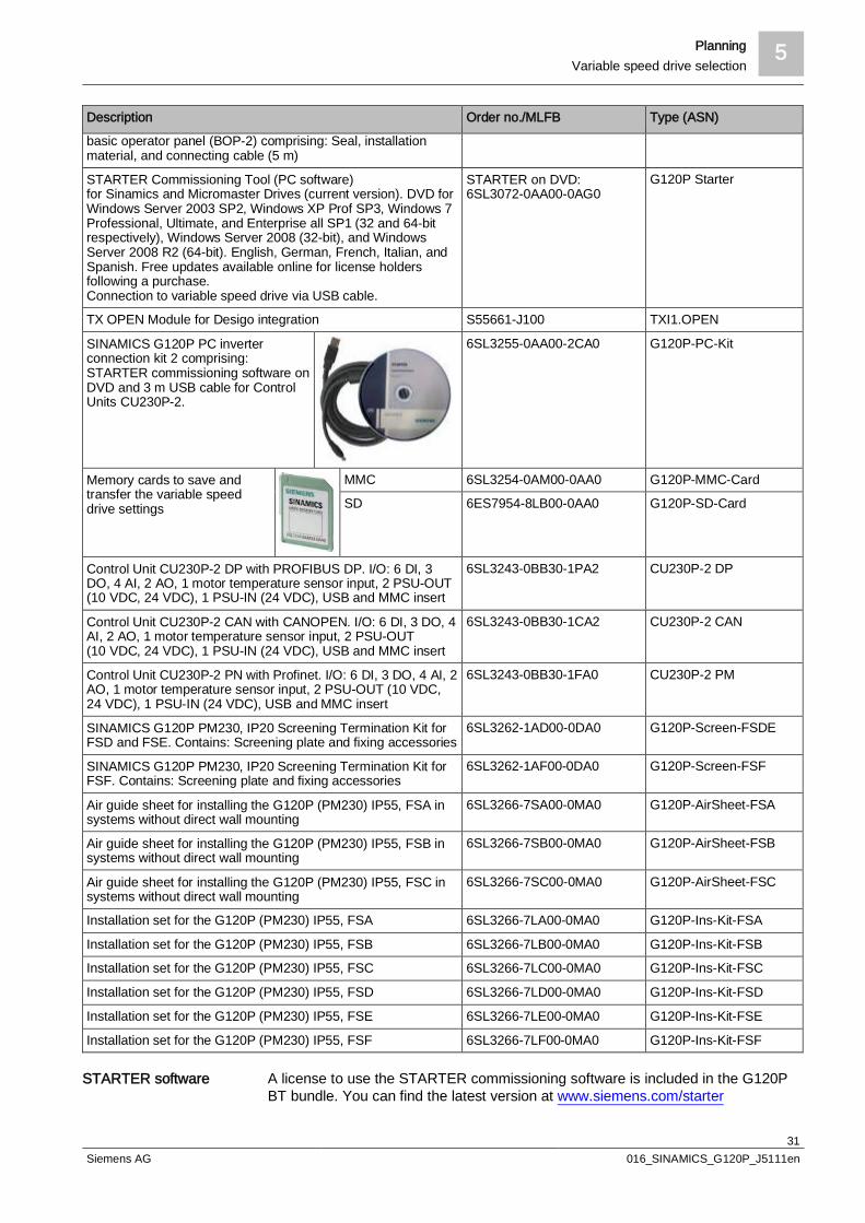
5.1.4 AccessoriesDescription Order no./MLFB Type (ASN)
BOP-2, SINAMICS G120P IP20/IP55, basic operator panel forsnapping onto the variable speed drivel Copying drive parametersl Two-line displayl Guided commissioning
6SL3255-6AA00-4CA0 G120P-BOP-2
IOP, SINAMICS G120P IP20/IP54, intelligent operator panel forsnapping onto the variable speed drivel Copying drive parametersl Plain text displayl Menu-based operation and application wizards
6SL3255-6AA00-4JA1 G120P-IOP-2
SINAMICS G120P blanking cover for POWER MODULEPM230, IP55/UL Type 12 degree of protection
6SL3256-6BA00-0AA0 G120P-BCover
SINAMICS G120P door mounting kit IOP (IP54) or BOP-2(IP55), KIT UL TYPE 12 for intelligent operator panel (IOP) and
6SL3256-6AP00-0JA0 G120P-Door-Kit
Planning 5Variable speed drive selection
31Siemens AG 016_SINAMICS_G120P_J5111en
Description Order no./MLFB Type (ASN)
basic operator panel (BOP-2) comprising: Seal, installationmaterial, and connecting cable (5 m)
STARTER Commissioning Tool (PC software)for Sinamics and Micromaster Drives (current version). DVD forWindows Server 2003 SP2, Windows XP Prof SP3, Windows 7Professional, Ultimate, and Enterprise all SP1 (32 and 64-bitrespectively), Windows Server 2008 (32-bit), and WindowsServer 2008 R2 (64-bit). English, German, French, Italian, andSpanish. Free updates available online for license holdersfollowing a purchase.Connection to variable speed drive via USB cable.
STARTER on DVD:6SL3072-0AA00-0AG0
G120P Starter
TX OPEN Module for Desigo integration S55661-J100 TXI1.OPEN
SINAMICS G120P PC inverterconnection kit 2 comprising:STARTER commissioning software onDVD and 3 m USB cable for ControlUnits CU230P-2.
6SL3255-0AA00-2CA0 G120P-PC-Kit
Memory cards to save andtransfer the variable speeddrive settings
MMC 6SL3254-0AM00-0AA0 G120P-MMC-Card
SD 6ES7954-8LB00-0AA0 G120P-SD-Card
Control Unit CU230P-2 DP with PROFIBUS DP. I/O: 6 DI, 3DO, 4 AI, 2 AO, 1 motor temperature sensor input, 2 PSU-OUT(10 VDC, 24 VDC), 1 PSU-IN (24 VDC), USB and MMC insert
6SL3243-0BB30-1PA2 CU230P-2 DP
Control Unit CU230P-2 CAN with CANOPEN. I/O: 6 DI, 3 DO, 4AI, 2 AO, 1 motor temperature sensor input, 2 PSU-OUT(10 VDC, 24 VDC), 1 PSU-IN (24 VDC), USB and MMC insert
6SL3243-0BB30-1CA2 CU230P-2 CAN
Control Unit CU230P-2 PN with Profinet. I/O: 6 DI, 3 DO, 4 AI, 2AO, 1 motor temperature sensor input, 2 PSU-OUT (10 VDC,24 VDC), 1 PSU-IN (24 VDC), USB and MMC insert
6SL3243-0BB30-1FA0 CU230P-2 PM
SINAMICS G120P PM230, IP20 Screening Termination Kit forFSD and FSE. Contains: Screening plate and fixing accessories
6SL3262-1AD00-0DA0 G120P-Screen-FSDE
SINAMICS G120P PM230, IP20 Screening Termination Kit forFSF. Contains: Screening plate and fixing accessories
6SL3262-1AF00-0DA0 G120P-Screen-FSF
Air guide sheet for installing the G120P (PM230) IP55, FSA insystems without direct wall mounting
6SL3266-7SA00-0MA0 G120P-AirSheet-FSA
Air guide sheet for installing the G120P (PM230) IP55, FSB insystems without direct wall mounting
6SL3266-7SB00-0MA0 G120P-AirSheet-FSB
Air guide sheet for installing the G120P (PM230) IP55, FSC insystems without direct wall mounting
6SL3266-7SC00-0MA0 G120P-AirSheet-FSC
Installation set for the G120P (PM230) IP55, FSA 6SL3266-7LA00-0MA0 G120P-Ins-Kit-FSA
Installation set for the G120P (PM230) IP55, FSB 6SL3266-7LB00-0MA0 G120P-Ins-Kit-FSB
Installation set for the G120P (PM230) IP55, FSC 6SL3266-7LC00-0MA0 G120P-Ins-Kit-FSC
Installation set for the G120P (PM230) IP55, FSD 6SL3266-7LD00-0MA0 G120P-Ins-Kit-FSD
Installation set for the G120P (PM230) IP55, FSE 6SL3266-7LE00-0MA0 G120P-Ins-Kit-FSE
Installation set for the G120P (PM230) IP55, FSF 6SL3266-7LF00-0MA0 G120P-Ins-Kit-FSF
A license to use the STARTER commissioning software is included in the G120PBT bundle. You can find the latest version at www.siemens.com/starter
STARTER software

5 PlanningVariable speed drive selection
32Siemens AG 016_SINAMICS_G120P_J5111en
STARTER is also included as a DVD version in the SINAMICS G120P PC inverterconnection kit 2 accessory and can be ordered separately.
5.1.5 Spare partsDescription Order no./MLFB Type (ASN)
Control Unit CU230P-2 BT with USS, MODBUS RTU,BACNET MS/TP. I/O: 6 DI, 3 DO, 4 AI, 2 AO, 1 motortemperature sensor input, 2 PSU-OUT (10 VDC, 24 VDC), 1PSU-IN (24 VDC), USB and MMC insert.
6SL3243-6BB30-1HA3 CU230P-2 BT
SINAMICS G120P CU Screening Termination Kit 1 contains:Screening plate and fixing accessories for the CONTROLUNIT CU230P-2
6SL3264-1EA00-0FA0 G120P-CUScreen
SINAMICS G120P PM230, IP20 Screening Termination Kitfor FSA. Contains: Screening plate and fixing accessories
6SL3266-1EA00-0KA0 G120P-Screen-FSA
SINAMICS G120P PM230, IP20 Screening Termination Kitfor FSB. Contains: Screening plate and fixing accessories
6SL3266-1EB00-0KA0 G120P-Screen-FSB
SINAMICS G120P PM230, IP20 Screening Termination Kitfor FSC. Contains: Screening plate and fixing accessories
6SL3266-1EC00-0KA0 G120P-Screen-FSC
SINAMICS G120P mounting set for the POWER MODULEPM230 IP55/UL TYPE 12 FSA G120P
6SL3200-0SK02-0AA0 G120P-MSetFSA-IP55
SINAMICS G120P mounting set for the POWER MODULEPM230 IP55/UL TYPE 12 FSB G120P
6SL3200-0SK03-0AA0 G120P-MSetFSB-IP55
SINAMICS G120P mounting set for the POWER MODULEPM230 IP55/UL TYPE 12 FSC G120P
6SL3200-0SK04-0AA0 G120P-MSetFSC-IP55
SINAMICS G120P mounting set for the POWER MODULEPM230 IP55/UL TYPE 12 FSD G120P
6SL3200-0SK05-0AA0 G120P-MSetFSD-IP55
SINAMICS G120P mounting set for the POWER MODULEPM230 IP55/UL TYPE 12 FSE G120P
6SL3200-0SK06-0AA0 G120P-MSetFSE-IP55
SINAMICS G120P mounting set for the POWER MODULEPM230 IP55/UL TYPE 12 FSF G120P
6SL3200-0SK07-0AA0 G120P-MSetFSF-IP55
External fan unit for PM230 IP20 and IP55/UL Type 12 FSAand PM2x0
6SL3200-0SF21-0AA0 G120P-FExtFSA
External fan unit for PM230 IP20 and IP55/UL type 12 FSBand PM2x0
6SL3200-0SF22-0AA0 G120P-FExtFSB
External fan unit for PM230 IP20 and IP55/UL Type 12 FSCand PM2x0
6SL3200-0SF23-0AA0 G120P-FExtFSC
External fan unit for PM230, IP20 FSD and FSE 6SL3200-0SF05-0AA0 G120P-FExtFSDE-IP20
External fan unit for PM230, IP20 FSF 6SL3200-0SF08-0AA0 G120P-FExtFSF-IP20
Internal fan unit for PM230 IP55/UL Type 12 FSA, FSB, andFSC
6SL3200-0SF31-0AA0 G120P-FIntFSAC-IP55
External fan unit for PM230, IP55/UL TYPE 12 FSD and FSE 6SL3200-0SF24-0AA0 G120P-FExtFSDE-IP55
External fan unit for PM230, IP55/UL TYPE 12 FSF 6SL3200-0SF26-0AA0 G120P-FExtFSF-IP55
Internal fan unit for PM230 IP55/UL type 12 FSD, FSE, andFSF
6SL3200-0SF32-0AA0 G120P-FIntFSDF-IP55
5.1.6 Service life of the fanThe average service life of fans is 40,000 hours. In practice, the service life maydiffer from this value, in particular in dusty environments.
Planning 5Variable speed drive selection
33Siemens AG 016_SINAMICS_G120P_J5111en
The fan must be replaced in good time in order to ensure that the drive remainsready for operation.
Replacing the fanInformation about replacing the fan can be found in the following manuals:l Hardware Installation Manual for Power Module PM230 IP55/UL Type 12
(A5E02923635A AA)l Hardware Installation Manual for Power Module PM230 IP20
(A5E03448282A AA)The fans are available as spare parts through your local Siemens branch office.
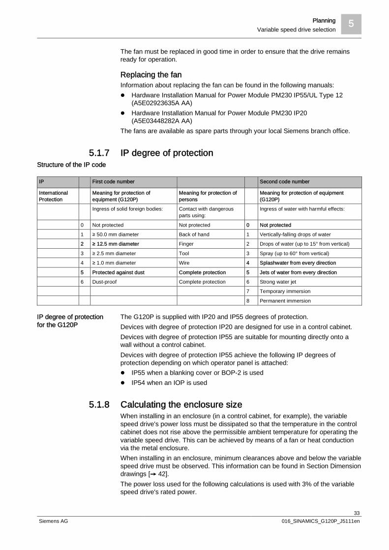
5.1.7 IP degree of protection
IP First code number Second code number
InternationalProtection
Meaning for protection ofequipment (G120P)
Meaning for protection ofpersons
Meaning for protection of equipment(G120P)
Ingress of solid foreign bodies: Contact with dangerousparts using:
Ingress of water with harmful effects:
0 Not protected Not protected 0 Not protected
1 ≥ 50.0 mm diameter Back of hand 1 Vertically-falling drops of water
2 ≥ 12.5 mm diameter Finger 2 Drops of water (up to 15° from vertical)
3 ≥ 2.5 mm diameter Tool 3 Spray (up to 60° from vertical)
4 ≥ 1.0 mm diameter Wire 4 Splashwater from every direction
5 Protected against dust Complete protection 5 Jets of water from every direction
6 Dust-proof Complete protection 6 Strong water jet
7 Temporary immersion
8 Permanent immersion
The G120P is supplied with IP20 and IP55 degrees of protection.Devices with degree of protection IP20 are designed for use in a control cabinet.Devices with degree of protection IP55 are suitable for mounting directly onto awall without a control cabinet.Devices with degree of protection IP55 achieve the following IP degrees ofprotection depending on which operator panel is attached:l IP55 when a blanking cover or BOP-2 is usedl IP54 when an IOP is used
5.1.8 Calculating the enclosure sizeWhen installing in an enclosure (in a control cabinet, for example), the variablespeed drive's power loss must be dissipated so that the temperature in the controlcabinet does not rise above the permissible ambient temperature for operating thevariable speed drive. This can be achieved by means of a fan or heat conductionvia the metal enclosure.When installing in an enclosure, minimum clearances above and below the variablespeed drive must be observed. This information can be found in Section Dimensiondrawings [ 42].The power loss used for the following calculations is used with 3% of the variablespeed drive's rated power.
Structure of the IP code
IP degree of protectionfor the G120P
5 PlanningVariable speed drive selection
34Siemens AG 016_SINAMICS_G120P_J5111en
For the precise calculations, the power loss and efficiency can be found in SectionType overview [ 27].
The required quantity of cooling air is calculated as follows:(G120P power loss + other heat in the enclosure) x 3.1 / dT = m3/hWith:power losses and other heat in [W]dT in [K]
Example:Power loss of 66 W (3% of 2.2 kW for example)No other heat sourcesPermissible ambient temperature for the G120P at low overload (LO) and withoutderating = 40 °CRoom temperature = 25 °CdT = 15 K (40 – 25)Calculation: (66 + 0) x 3.1 / 15 = 13.65A fan with a volume flow of 14 m3 is required.
The minimum enclosure surface required is calculated as follows:(G120P power loss + other heat in the enclosure) / 5.5 / dT = m2
With:power losses and other heat in [W]dT in [K]
Example:Power loss of 66 W (3% of 2.2 kW for example)No other heat sourcesPermissible ambient temperature for the G120P = 40 °CRoom temperature = 25 °CdT = 15 K (40 – 25)Calculation: (66 + 0) / 5.5 / 15 = 13.45An enclosure surface of at least 0.8 m2 is required.
w The following additional points are essential and must be observed:
1. Enclosures that contain variable speed drives must not be installed in locationsthat are exposed to direct sunlight. Even on relatively cool days, the heatingeffect can quickly lead to high temperatures building up in the enclosure.
2. If ambient temperatures sink below 10 °C while the variable speed drive is notin operation, heaters must be provided to prevent the ingress of condensation.
3. If fans with filters are inserted, then cleaning these filters must be part of thenormal maintenance routine.
Enclosure with fans
Enclosure without fan
Planning 5Variable speed drive selection
35Siemens AG 016_SINAMICS_G120P_J5111en
WARNING
Hazardous voltagesThe variable speed drive in the control cabinet carries lethal voltages which canstill be present for 5 minutes after switching off the device. Warning signs for these hazardous voltages must be attached to the
enclosures.
See also2 Dimension drawings [ 42]
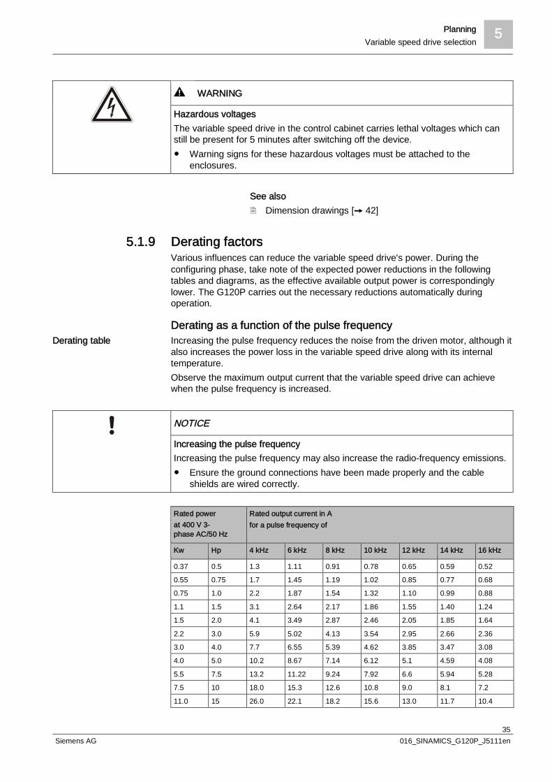
5.1.9 Derating factorsVarious influences can reduce the variable speed drive's power. During theconfiguring phase, take note of the expected power reductions in the followingtables and diagrams, as the effective available output power is correspondinglylower. The G120P carries out the necessary reductions automatically duringoperation.
Derating as a function of the pulse frequencyIncreasing the pulse frequency reduces the noise from the driven motor, although italso increases the power loss in the variable speed drive along with its internaltemperature.Observe the maximum output current that the variable speed drive can achievewhen the pulse frequency is increased.
NOTICE
Increasing the pulse frequencyIncreasing the pulse frequency may also increase the radio-frequency emissions. Ensure the ground connections have been made properly and the cable
shields are wired correctly.
Rated powerat 400 V 3-phase AC/50 Hz
Rated output current in Afor a pulse frequency of
Kw Hp 4 kHz 6 kHz 8 kHz 10 kHz 12 kHz 14 kHz 16 kHz
0.37 0.5 1.3 1.11 0.91 0.78 0.65 0.59 0.52
0.55 0.75 1.7 1.45 1.19 1.02 0.85 0.77 0.68
0.75 1.0 2.2 1.87 1.54 1.32 1.10 0.99 0.88
1.1 1.5 3.1 2.64 2.17 1.86 1.55 1.40 1.24
1.5 2.0 4.1 3.49 2.87 2.46 2.05 1.85 1.64
2.2 3.0 5.9 5.02 4.13 3.54 2.95 2.66 2.36
3.0 4.0 7.7 6.55 5.39 4.62 3.85 3.47 3.08
4.0 5.0 10.2 8.67 7.14 6.12 5.1 4.59 4.08
5.5 7.5 13.2 11.22 9.24 7.92 6.6 5.94 5.28
7.5 10 18.0 15.3 12.6 10.8 9.0 8.1 7.2
11.0 15 26.0 22.1 18.2 15.6 13.0 11.7 10.4
Derating table

5 PlanningVariable speed drive selection
36Siemens AG 016_SINAMICS_G120P_J5111en
Rated powerat 400 V 3-phase AC/50 Hz
Rated output current in Afor a pulse frequency of
Kw Hp 4 kHz 6 kHz 8 kHz 10 kHz 12 kHz 14 kHz 16 kHz
15.0 20 32.0 27.2 22.4 19.2 16.0 14.4 12.8
18.5 25 38.0 32.3 26.6 22.8 19.0 17.1 15.2
22 30 45.0 38.25 31.5 27.0 22.5 20.25 18.0
30 40 60.0 52.7 43.4 37.2 31.0 27.9 24.8
37 50 75.0 63.75 52.5 45.0 37.5 33.75 30.0
45 60 90.0 76.5 63.0 54.0 45.0 40.5 36.0
55 75 110 93.5 77.0 – – – –
75 100 145 123.3 101.5 – – – –
90 125 178 151.3 124.6
Derating in relation to the ambient temperature
Low overload (LO) forPower Modules PM230,frame sizes A to F
100
2535
0
50%7585
60°C504010 30200
G_D
011_
DE
_003
09
C(%
)
T (°C)T (°C) = ambient temperatureC (%) = permissible output current
High overload (HO) forPower Modules PM230,frame sizes A to F
100
25
0
50
%75
60°C504010 30200
G_D
011_
DE_
0030
8
T (°C)
C(%
)
T (°C) = ambient temperatureC (%) = permissible output current

Planning 5Variable speed drive selection
37Siemens AG 016_SINAMICS_G120P_J5111en
Derating in relation to the air pressure in meters above sea level
Permissible output currentin relation to theinstallation altitude
80
100%
0 1000 m
70
90
60
H (m)
G_D
011_
DE
_001
04
30002000 4000
C(%
)
H (m) = installation altitude above sea levelC (%) = permissible output current
Permissible input voltagein relation to theinstallation altitude
80
100%
m
77
70
90
60 G_D
011_
DE_
0010
5
U(%
)
H (m)0 1000 30002000 4000
H (m) = installation altitude above sea levelU (%) = permissible input voltage
Derating in relation to the line voltage
Permissible output currentin relation to the linevoltage
20
40
60
80
100%
0340342 528
360 380 400 420 440 460 480 500 V520 540
U (V)
C(%
)
G_D
011_
DE
_003
24
U (V) = line voltageC (%) = permissible output current
Permissible rated power inrelation to the line voltage
20
40
60
80
100%
0
342 528
G_D
011_
DE
_003
25
340 360 380 400 420 440 460 480 500 V520 540
P(%
)
U (V)

5 PlanningVariable speed drive selection
38Siemens AG 016_SINAMICS_G120P_J5111en
U (V) = line voltageP (%) = permissible rated power
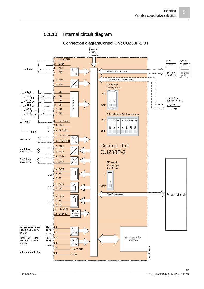
Planning 5Variable speed drive selection
39Siemens AG 016_SINAMICS_G120P_J5111en
5.1.10 Internal circuit diagram
Connection diagramControl Unit CU230P-2 BT

5 PlanningVariable speed drive selection
40Siemens AG 016_SINAMICS_G120P_J5111en
Connection diagram for Power Module PM230 with integrated linefilter class A or B

Planning 5Variable speed drive selection
41Siemens AG 016_SINAMICS_G120P_J5111en
5.1.11 Terminal strips in the Control Unit
The wiring of the terminal strip is displayed by way of an example for every type ofterminal.If more than 6 digital inputs are required, use terminals 3 and 4 (AI 0) or terminals10 and 11 (AI 1) as additional digital inputs DI 11 or DI 12.1. Wiring when using the internal power supplies
DI = high if the switch is closed2. Wiring when using the external power supplies
DI = high if the switch is closed3. Wiring when using the internal power supplies
DI = low if the switch is closed4. Wiring when using the external power supplies
DI = low if the switch is closed
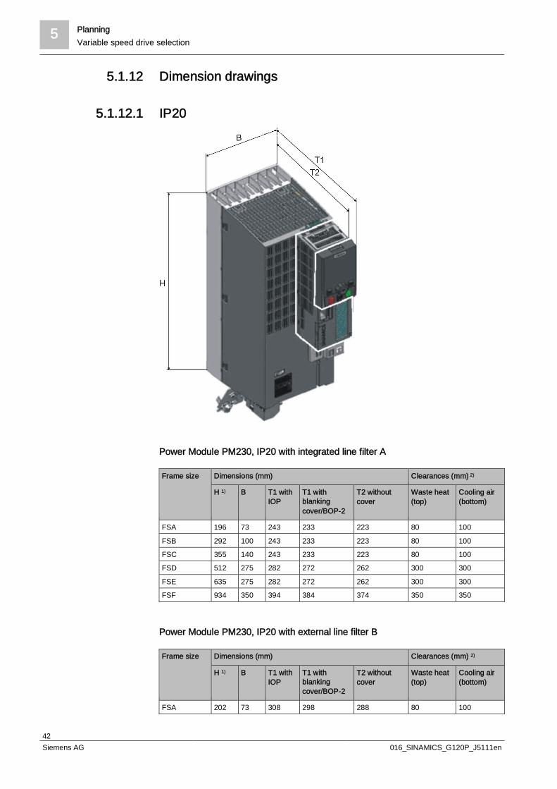
5 PlanningVariable speed drive selection
42Siemens AG 016_SINAMICS_G120P_J5111en
5.1.12 Dimension drawings
5.1.12.1 IP20
Power Module PM230, IP20 with integrated line filter A
Frame size Dimensions (mm) Clearances (mm) 2)
H 1) B T1 withIOP
T1 withblankingcover/BOP-2
T2 withoutcover
Waste heat(top)
Cooling air(bottom)
FSA 196 73 243 233 223 80 100
FSB 292 100 243 233 223 80 100
FSC 355 140 243 233 223 80 100
FSD 512 275 282 272 262 300 300
FSE 635 275 282 272 262 300 300
FSF 934 350 394 384 374 350 350
Power Module PM230, IP20 with external line filter B
Frame size Dimensions (mm) Clearances (mm) 2)
H 1) B T1 withIOP
T1 withblankingcover/BOP-2
T2 withoutcover
Waste heat(top)
Cooling air(bottom)
FSA 202 73 308 298 288 80 100
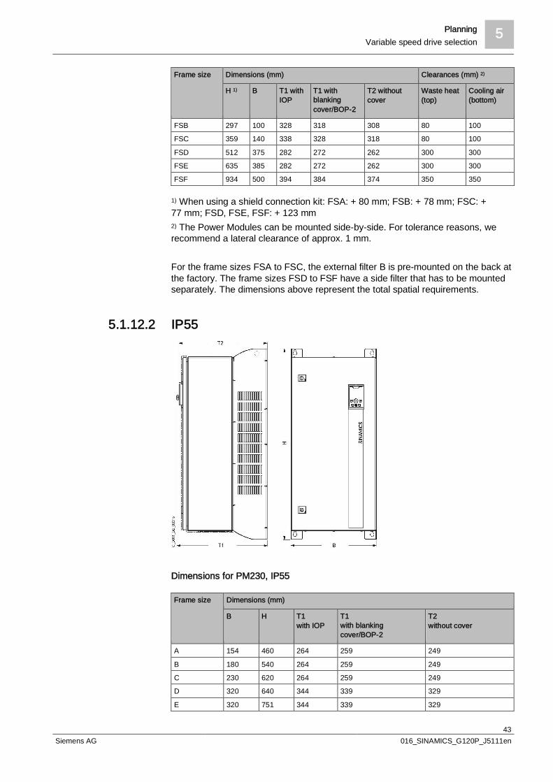
Planning 5Variable speed drive selection
43Siemens AG 016_SINAMICS_G120P_J5111en
Frame size Dimensions (mm) Clearances (mm) 2)
H 1) B T1 withIOP
T1 withblankingcover/BOP-2
T2 withoutcover
Waste heat(top)
Cooling air(bottom)
FSB 297 100 328 318 308 80 100
FSC 359 140 338 328 318 80 100
FSD 512 375 282 272 262 300 300
FSE 635 385 282 272 262 300 300
FSF 934 500 394 384 374 350 350
1) When using a shield connection kit: FSA: + 80 mm; FSB: + 78 mm; FSC: +77 mm; FSD, FSE, FSF: + 123 mm2) The Power Modules can be mounted side-by-side. For tolerance reasons, werecommend a lateral clearance of approx. 1 mm.
For the frame sizes FSA to FSC, the external filter B is pre-mounted on the back atthe factory. The frame sizes FSD to FSF have a side filter that has to be mountedseparately. The dimensions above represent the total spatial requirements.
5.1.12.2 IP55
Dimensions for PM230, IP55
Frame size Dimensions (mm)
B H T1with IOP
T1with blankingcover/BOP-2
T2without cover
A 154 460 264 259 249
B 180 540 264 259 249
C 230 620 264 259 249
D 320 640 344 339 329
E 320 751 344 339 329
5 PlanningMotor selection
44Siemens AG 016_SINAMICS_G120P_J5111en
Frame size Dimensions (mm)
B H T1with IOP
T1with blankingcover/BOP-2
T2without cover
F 410 915 431 426 416
To ensure the cooling capacity, IP55 devices in frame sizes FSA to FSC must bemounted directly onto a flat wall. If this is not possible, for example in the case of asuspended installation on a busbar system, an air guide sheet (availableseparately) must be attached.This is cut to size and comes with the corresponding holes so it can be screweddirectly onto the rear of the Power Module.You can find the available air guide sheets and their order numbers in SectionAccessories [ 30].
5.2 Motor selectionThe technical requirements and ambient conditions play a decisive role whenselecting the motor.
Rated frequencyRated voltage
Operating mode
Degree of protection or type of explosionprotection required
Rated speed (number of poles)
Rated power
Rated torque
Construction type
3-phase AC 50/60 Hz400 or 500 V
Normal operation (continuous operation S1according toDIN EN 60034-1)IP…
n = ……rpm
P = ……kW
M = P x 9,950 / n =…….Nm
IM……
Consult the motor manufacturer to find out whether the motor is suitable for directvariable speed drive operation.
Ambient temperature
Installation altitude
Factors for changes in power
≤ 40 ºC
≤ 1,000 m
None
> 40 ºC
> 1,000 m
Determine the factor for changesin power (for reduction factor,see "Coolant temperature andinstallation altitude"). SeeSection Derating factors [ 35]
The induction motor must be able to provide the required torque, even in theprocess overload range. The thermal overload torque of the induction motor,however, must not be exceeded.A reserve of approximately 10 to 30% is generally added to the motor torque/powerrequirements. This depends on whether the process is direct-driven or, forexample, driven by a belt or gearbox.
Rear panels
Technical requirements
Ambient conditions
Rated torque
Planning 5Compressor operation
45Siemens AG 016_SINAMICS_G120P_J5111en
NOTICE
Undersized motorsUndersized motors cause overvoltages and overcurrents in the variable speeddrive and the motor. In the longer term, the permanent overloading leads to areduction in the motor's service life and permanent overcurrent alarms in theupper output frequency range of the variable speed drive.The G120P calculates an I2T model of the motor and outputs alarms indicatingovercurrents and temperature rises. The G120P only controls the motor up to therated current in order to protect both the motor and the variable speed drive. Thismeans that motors with overly weak dimensions cannot reach the outputfrequency of 50 Hz. Ensure that the motor and the variable speed drive are compatible with each
other. Ensure that the motor's planned operating point is not at the upper end of the
rated torque.
With its comprehensive physical and technical background knowledge, SIZERsoftware provides the user with motor configuration support. You can find it at:www.siemens.com/sizer
5.3 Compressor operationCompressors often require a starting current that is significantly above its base-load current. This means that the selected Power Module must be correspondinglylarger to ensure that it is able to supply the required current.The size of the Power Module also depends on permitted current overload setting.
The G120P has two settings (p0205) for current overload (in % based on thevariable speed drive's base-load current):l HO Duty cycle with high overload (setting 0)
Up to 15 kW200% for 3 s and 150% for 57 s (once per 300 s cycle)From 18.5 kW150% for 60 s (once per 300 s cycle)
l LO Duty cycle with slight overload (setting 1)Up to 18.5 kW150% for 3 s and 110% for 57 s (once per 300 s cycle)From 22 kW110% for 60 s (once per 300 s cycle)
Selecting HO instead of LO reduces the G120P's power rating by one frame size.In doing so, the operating temperature is increased from 40 °C to 50 °C withoutpower reduction (derating) and a larger overload is possible.
A semi-hermetic reciprocating compressor with a rated power of 4.5 kW has abase-load current of 8 A, yet requires a starting current of 16 A when starting up.The closest Power Module that can produce this starting current is the 7.5 kWmodel. This produces a LO output current of 18 A at an ambient temperature ofmax. 40 °C.
Order number 6SL3200-6AM21-0AH0 6SL3200-6AM21-3AH0 6SL3200-6AM21-8AH0
Type G120P-4/35A G120P-5.5/35A G120P-7.5/35A
Configuring tool formotors
HO and LO
Example

5 PlanningCompressor operation
46Siemens AG 016_SINAMICS_G120P_J5111en
LO power 4 kW 5.5 kW 7.5 kW
LO input current 10.5 A 13.6 A 18.6 A
LO output current 10.2 A 13.2 A 18 A
HO power 3 kW 4 kW 5.5 kW
HO input current 8.0 A 10.5 A 13.6 A
HO output current 7.7 A 10.2 A 13.2 A
The HO output power is still 13.2 A. At an overload of 150% and a permissibleambient temperature of 50 °C, its 19.8 A are significantly higher than the required16 A.
w We have used the HO solution as an example. Please proceed as follows:
1. Set the overload to HO (p0205 = 0)
2. Perform basic commissioning with motor identification
3. Set the current limit (p0640) to 16 A
The size and duration of the required compressor starting current are dependenton various factors. There are no general statements that can be made in thisregard, so either contact the compressor manufacturer for the values or use yourown experience.
For centrifugal or turbo compressors (axial or radial) the "V/f" open-loop controloperating mode is adequate. This is the default operating mode.For rotation compressors (rotary piston, root, scroll, screw, liquid ring, and rotaryslide compactors) and piston compressors the sensorless vector control (SLVC)closed-loop operating mode is better suited.This has a higher dynamic power than the V/f operating mode (calculation basedon the characteristic only) and is less susceptible to false tripping as a result ofvarious load-related issues. More information about the control modes is providedunder Control modes of the G120P [ 17].The setting can be made using the STARTER software, IOP, or BOP-2. Pleaseproceed as follows:
1. Select the open-loop/closed-loop control operating mode parameter on linep1300
2. Select the setting 20: (Encoderless) speed control
3. Perform the motor identification by selecting motor data identification on linep1900
4. Select the setting 1: Motor data identification at standstill and when the motor isrotating
a A corresponding alarm is generated
5. Switch on the drive – the motor data identification is now performed
6. Switch the drive back off
a The variable speed drive is now in the SLVC control mode and the motoridentification is complete. The alarm disappears.
The motor data identification can take from 0.3 s to a few minutes. This allows themotor to align itself by up to a quarter of a revolution.You can also make these settings as part of the basic commissioning process.
V/f vs. SLVC

Planning 5Operating motors at higher frequencies
47Siemens AG 016_SINAMICS_G120P_J5111en
w You can then save the settings by transferring them to the non-volatilememory.
1. Select the Save parameters parameter on line p0971
2. Select the setting 10: Save in a non-volatile memory as setting 10
a The settings have now been transferred from the RAM to the ROM.
If you would like to use the V/f control operating mode, select p1300 = 1 (V/f controlwith linear characteristic).
5.4 Operating motors at higher frequencies
5.4.1 GeneralIn addition to variable speeds of up to nrated, operation on a variable speed drivealso enables speeds that are above the rated speed. There are two possibilities:l Field weakening model Operation with 87 Hz characteristic
To operate a motor above the rated motor speed, the variable speed drive andmotor must be laid out accordingly with the appropriate parameters assigned. Payattention to the following values:l The mechanical limit speedsl The increased thermal stressl The increased voltage stress on the motorl The variable speed drive's modulation depth
To achieve higher speeds, it is better to select a motor that has a rated speed closeto the operating speed.
To achieve an operating speed of 1,800 rpm, consider what would be best suitedto the application: a 4-pole motor with a synchronous motor speed of 1,500 rpmand a correspondingly higher frequency, or a 2-pole motor with a synchronousmotor speed of 3,000 rpm and a correspondingly lower frequency.
A motor with the following rating plate is taken as a basis for the followingcalculation examples for both field weakening mode and operation with the 87 Hzcharacteristic:
5.4.2 Field weakening modeIn a physical sense, the field weakening of a motor begins when the variable speeddrive's output voltage can no longer be increased but the frequency continues torise.
Example
Motor rating plate as acalculation example

5 PlanningOperating motors at higher frequencies
48Siemens AG 016_SINAMICS_G120P_J5111en
Generally speaking, "field weakening mode" refers to operating a motor above therated motor frequency with a constant supply voltage.The parameters assigned to the variable speed drive for this operating mode havea maximum speed that is greater than the rated speed (for example1,800 rpm/400 V). As the variable speed drive frequency is increased, the outputvoltage remains constant, the speed increases, but the torque decreases as theflux in the machine decreases.At constant power, the torque decreases at a rate which is inversely proportional tothe speed.Operation in field weakening mode does not depend on the motor's connectiontype (star or delta).
The example motor should run at an (asynchronous) operating speed of 2250 rpm.Star connection.
Required settingsThe motor data is set according to the rating plate. Only the data for the maximumspeed (p1082) and the reference speed (p2000) has to be set to the requiredvalue.
Parameters Description
p0304 Rated motor voltage: 400 V
p0305 Rated motor current: 0.42 A
p0307 Rated motor output: 0.12 kW
p0308 Motor cosPhi: 0.75
p0310 Motor frequency: 50 Hz
p0311 Rated motor speed: 1350 rpm
p0314 Motor pole pairs: 2
p0350 Stator resistance according to measurement (MotID)
p1082 Maximum speed 2,250 rpm
p2000 Reference speed: 2,250 rpm
The following calculations are made within the device. The G120P automaticallysets the parameters according to the calculation results.
Abbreviations
f = Frequency according to rating plate = 50 Hzfoperation = Required operating frequency
Moperation = Operating torqueMKred = Reduced breakdown torquen = Speed according to the rating plate = 1,350 rpm
nsynchron1 = Synchronous speed at 50 Hz = 1,500 rpmnoperation = Required operating speedp = Pole pair
s = Slip
Calculating the required operating frequencyCalculate the 50 Hz slip speed nS1:S = nsynchron1 – n = 1,500 – 1,350 = 150 rpm
Example for calculationpurposes
Example parametersettings
Internal calculations
Planning 5Operating motors at higher frequencies
49Siemens AG 016_SINAMICS_G120P_J5111en
As a result of the specified operating speed (2,250 rpm), the operating frequency isidentified as 80 Hz.
Calculating the motor torque for the field weakening rangeMotor catalog data:l Δ 230 V; 50 Hz; 0.73 A; 0.12 kW; 1,350 rpml Y 400 V; 50 Hz; 0.42 A; 0.12 kW; 1,350 rpml Rated torque MN = 0.85 Nml Motor breakdown torque Mk = 2 Nml Operating frequency foperation = 80 Hz
In the case of the motor in the example, this produces an operating torque of0.53 Nm at an operating frequency of 80 Hz.
Calculating the reduced breakdown torque for the field weakening range (MKRed)
In the case of the motor in the example, this produces a reduced breakdown torqueof 0.78 Nm for 80 Hz.In order to guarantee reliable operation in the field-weakening range, the differencebetween the reduced breakdown torque (MKred) and the (maximum possible)operating torque (Moperation max) must be more than 30%.This is calculated as follows:
The breakdown limit for the motor in the example is 147% of the operating point. Inthe case of the motor in the example, this results in a margin of 47% (MKRed -MKOperation = 147% - 100%). Under the prerequisite that the motor is not subjectto a load higher than 0.53 Nm in continuous operation at the operating point, then itmay be operated at up to 80 Hz in field weakening.
If changes are made to p2000, the analog input and the serial connection areautomatically re-scaled so that the full scale corresponds to this value. Anadditional parameter that is re-scaled as a consequence of changing p2000 is, forexample, the frequency displayed at the analog output.For scaling f*, parameters p0757 - p0760 should be observed.
5.4.3 87 Hz characteristicAs a result of the relatively constant flux in the range above the rated motorfrequency, the 87 Hz characteristic offers an interesting variant.
Information regarding the motor
Example parametersettings
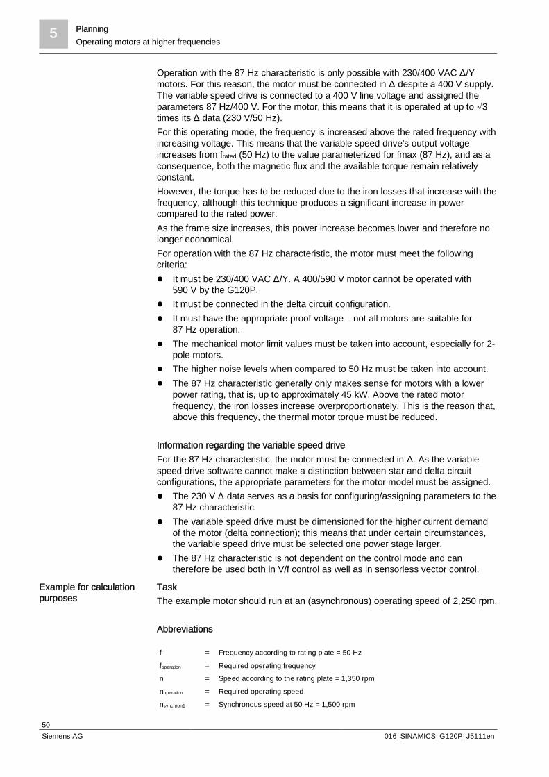
5 PlanningOperating motors at higher frequencies
50Siemens AG 016_SINAMICS_G120P_J5111en
Operation with the 87 Hz characteristic is only possible with 230/400 VAC Δ/Ymotors. For this reason, the motor must be connected in Δ despite a 400 V supply.The variable speed drive is connected to a 400 V line voltage and assigned theparameters 87 Hz/400 V. For the motor, this means that it is operated at up to √3times its Δ data (230 V/50 Hz).For this operating mode, the frequency is increased above the rated frequency withincreasing voltage. This means that the variable speed drive's output voltageincreases from frated (50 Hz) to the value parameterized for fmax (87 Hz), and as aconsequence, both the magnetic flux and the available torque remain relativelyconstant.However, the torque has to be reduced due to the iron losses that increase with thefrequency, although this technique produces a significant increase in powercompared to the rated power.As the frame size increases, this power increase becomes lower and therefore nolonger economical.For operation with the 87 Hz characteristic, the motor must meet the followingcriteria:l It must be 230/400 VAC Δ/Y. A 400/590 V motor cannot be operated with
590 V by the G120P.l It must be connected in the delta circuit configuration.l It must have the appropriate proof voltage – not all motors are suitable for
87 Hz operation.l The mechanical motor limit values must be taken into account, especially for 2-
pole motors.l The higher noise levels when compared to 50 Hz must be taken into account.l The 87 Hz characteristic generally only makes sense for motors with a lower
power rating, that is, up to approximately 45 kW. Above the rated motorfrequency, the iron losses increase overproportionately. This is the reason that,above this frequency, the thermal motor torque must be reduced.
Information regarding the variable speed driveFor the 87 Hz characteristic, the motor must be connected in Δ. As the variablespeed drive software cannot make a distinction between star and delta circuitconfigurations, the appropriate parameters for the motor model must be assigned.l The 230 V Δ data serves as a basis for configuring/assigning parameters to the
87 Hz characteristic.l The variable speed drive must be dimensioned for the higher current demand
of the motor (delta connection); this means that under certain circumstances,the variable speed drive must be selected one power stage larger.
l The 87 Hz characteristic is not dependent on the control mode and cantherefore be used both in V/f control as well as in sensorless vector control.
TaskThe example motor should run at an (asynchronous) operating speed of 2,250 rpm.
Abbreviations
f = Frequency according to rating plate = 50 Hz
foperation = Required operating frequencyn = Speed according to the rating plate = 1,350 rpmnoperation = Required operating speed
nsynchron1 = Synchronous speed at 50 Hz = 1,500 rpm
Example for calculationpurposes

Planning 5Operating motors at higher frequencies
51Siemens AG 016_SINAMICS_G120P_J5111en
nsynchron Synchronous speed at 87 HznS1 Slip speed at 50 HznS Slip speed at 87 Hz
p = Pole pairs = SlipUN = Line voltage 50 Hz (230 V)
UN1 = Line voltage 87 Hz (400 V)
The following calculations are made automatically when using STARTER or IOP.The calculations must be performed manually when using BOP-2.
Calculating the required operating frequencyl Calculate the 50 Hz slip speed nS1:l S = nsynchron1 – n = 1,500 – 1,350 = 150 rpm
Calculating the synchronous speed at 87 Hz
Calculating the slip speed at 87 Hz
The STARTER software uses an algorithm to convert the settings to those for the87 Hz characteristic. The process is slightly different depending on which firmwareversion is used.
w From firmware 4.4.1
1. During the commissioning process, enter the 230 V motor data in the"Configuration/Drive data" screen.
2. Then select the check mark to calculate the 87 Hz characteristic.
Setting parameters withSTARTER
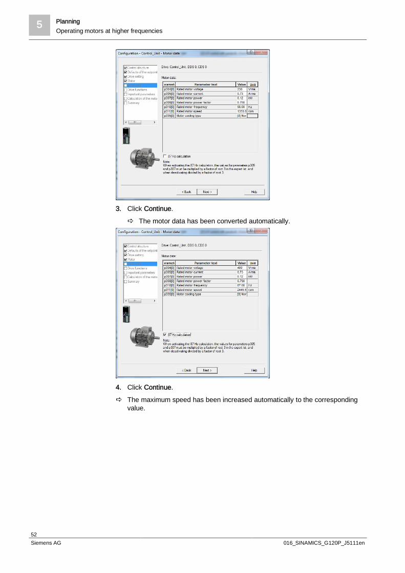
5 PlanningOperating motors at higher frequencies
52Siemens AG 016_SINAMICS_G120P_J5111en
3. Click Continue.
a The motor data has been converted automatically.
4. Click Continue.
a The maximum speed has been increased automatically to the correspondingvalue.

Planning 5Operating motors at higher frequencies
53Siemens AG 016_SINAMICS_G120P_J5111en
w From firmware 4.6
1. During the commissioning process, select the "delta" connection type in the"Configuration/Motor" screen.
2. Click Continue.
3. Enter the 230 V motor data in the "Configuration/Drive data" screen and selectthe check mark to calculate the 87 Hz characteristic.
a The motor data is not changed in the process.

5 PlanningOperating motors at higher frequencies
54Siemens AG 016_SINAMICS_G120P_J5111en
4. Click Continue.
a The motor data has been internally adjusted and the maximum speed has beenincreased automatically to the corresponding value.
When assigning parameters using an intelligent operator panel (IOP), the 87 Hzcharacteristic option can be selected. Then you can simply enter the 230 V motordata, just like for the configuration with the STARTER software. The G120P thenconverts the values automatically.Enter the data as follows:
Parameters Description
p0304 Rated motor voltage: 230 V
p0305 Rated motor current: 0.42 A
p0307 Rated motor output: 0.12 kW
p0308 Motor cosPhi: 0.75
p0310 Motor frequency: 50 Hz
p0311 Rated motor speed: 1,350 rpm
Setting parameters withIOP

Planning 5Operating motors at higher frequencies
55Siemens AG 016_SINAMICS_G120P_J5111en
Once the calculation is complete, the parameters are set as follows for thisexample: (From firmware 4.6, the rating plate data is no longer changed):
Parameters Description
p0304 Rated motor voltage: 400 V
p0305 Rated motor current: 0.73 A
p0307 Rated motor output: 0.21 kW
p0308 Motor cosPhi: 0.75
p0310 Motor frequency: 87 Hz
p0311 Rated motor speed: 2,455 rpm
p1082 Maximum speed: 2,610 rpm
p2000 Reference speed: 2,610 rpm
From firmware 4.4.1
w The BOP-2 basic operator panel does not have an integrated conversionalgorithm for the 87 Hz characteristic. This means the appropriate calculationshave to be completed manually. You can make the necessary settings(including motor parameters) during the setup process.
l For this example, enter the following values:
Parameters Description
p0304 Rated motor voltage: 400 V
p0305 Rated motor current: 0.73 A
p0307 Rated motor output: 0.21 kW
p0308 Motor cosPhi: 0.75
p0310 Motor frequency: 87 Hz
p0311 Rated motor speed: 2,460 rpm
p1082 Maximum speed: 2,610 rpm
p2000 Reference speed: 2,610 rpm
From firmware 4.6
1. Make the settings for p0010=3 (motor commissioning)
2. Make the settings for p0133.0=1 (delta connection) and for p0133.1=1 (87 Hz)
3. Make the settings for p0010=0 (ready)
4. Now complete the setup (without restoring the factory settings) and enter themotor data for the delta connection
If changes are made to p2000, the analog output and the serial connection areautomatically re-scaled so that the full scale corresponds to this value. Thefrequency displayed at the analog output is also re-scaled as a consequence ofchanging p2000.For scaling the scaling characteristic, parameters p0757 - p0760 should beobserved.p0350 applies for the phase value of the stator resistance; the value of theequivalent circuit diagram can be written directly into parameter p0350.
Setting parameters withBOP-2
Further informationregarding the 87 Hzcharacteristic
5 PlanningEMC
56Siemens AG 016_SINAMICS_G120P_J5111en
5.5 EMC
5.5.1 Basic principlesEMC stands for "electromagnetic compatibility" and essentially refers to therequirement that there must be no unacceptable mutual interference or damagewhen operating electrical devices.A distinction is made between various known phenomena, such as radio frequencyinterferences, line harmonic distortions, overvoltages, electromagneticinterferences, and other such interferences by the increased use of powerelectronic devices, microelectronics in automation engineering, and an increasingnumber of radio services, etc.
5.5.2 StandardsTo ensure no disturbances arise, you must observe the emission limit values andthe tolerance of specific immission limit values (immunity).The following standards are particularly significant to variable speed drives withregard to EMC:l Environment standard EN 55011
Radio frequency interferences – limit values and measuring procedures forindustrial, scientific, and medical devices
l Product standard EN 61800-3EMC requirements/test methods for variable-speed electrical drives
l Standard for connecting to public low-voltage networks EN 61000-3-12/EN61000-3-2. Requirements and limit values for harmonic component currents
All G120Ps are CE-certified and therefore manufactured in accordance with thestandards. Different EMC grades are offered depending on the type. Depending onthe location of use (environment), the following classes should be observed toensure smooth operation:
Use in Class according to EN55011
Class according to EN61800-3
First environment (residential andcommercial areas)
Class B, A1 Class C1, C2
Second environment (industrial areas) Class A2 Class C3, C4
The most cost-effective way to ensure a system runs smoothly is to consider thesubject of EMC as early as possible, for example, EMC zones should be defined,cable types determined, and filters provided as early as the planning phase.
5.5.2.1 Environment standard EN 55011The environment standard is a universal standard for devices without a specificproduct standard. It defines emission limit values and the device immunityrequirements depending on the location of use.The following 2 classes are relevant for variable speed drives:
Use in Class according to EN 55011
First environment (residential and commercial areas) Class B, A1

Planning 5EMC
57Siemens AG 016_SINAMICS_G120P_J5111en
Use in Class according to EN 55011
Second environment (industrial areas) Class A2
The limit values for class B (residential and commercial areas) are significantlylower than those for class A1 (industrial areas).Industrial areas also have class A2 for high-frequency applications. This class isnot relevant for variable speed drives.
5.5.2.2 Product standard EN 61800-3In EMC product standard EN 61800-3, criteria for performance during interferencehave been established and the immunity requirements and interference emissionlimiting values have been defined according to the ambient conditions at thelocation of use.The standard does not apply directly to a variable speed drive but to a completedrive system, which comprises the complete circuitry, motor and cables in additionto the variable speed drive.
Drive system (PDS) according to EN 61800-3:
PDS: Power Drive SystemCDM: Complete Drive ModuleBDM: Basic Drive Module
ApplicationsThe permitted limit values are dependent on the application area. A distinction ismade between "first environment" and "second environment". Depending on theenvironment, various device categories are admitted and diverse requirements areplaced on filters and shielding.
Connected to public low-voltage network"Residential area" = "First environment"
Connected to medium-voltage network via owntransformer"Industrial network" = "Second environment"

5 PlanningEMC
58Siemens AG 016_SINAMICS_G120P_J5111en
l Large volume of low-cost equipmentl Few potential sources of interferencel Low limit values
l Many potential sources of interferencel Interference-resistant devicesl High limit values
l Integrated filter class B according to EN55011
l Shielded motor cable,IP55 max. 25 mIP20 max. 50 m
l Line harmonic distortions according to EN61000-3-2 and EN 61000-3-12 must beobserved
l Integrated filter class A1 according to EN55011
l Shielded motor cable, max. 25 ml Other conditions must be met for use in the
first environment (sales and installation byprofessionals, supply voltage < 1,000 V,approval of the network operator, etc.)
l Filter is unnecessaryl Unshielded motor cable is possiblel Separate EMC planning
The Power Module PM230 is typically inserted in categories C1 and C2.The PM230 IP20 or PT are available with an integrated class A line filter or with anexternal class B filter.The PM230 IP55/UL type 12 are available with an integrated class A or B line filter.Unfiltered devices can also be supplied if required, although these are not normallyused in building management systems as they do not meet the EMC standards.
NOTICE
Using unshielded cables and insufficient shield supportIt is not possible to observe the limit values with unshielded cables andinsufficient shield support, as the effect on interference sinks from resultingdisturbance variables can be too great. The limit values are only achieved withshielded cables and good shield support. Please refer to the relevant specifications in Section EMC-compliant wiring [
75].

Planning 5EMC
59Siemens AG 016_SINAMICS_G120P_J5111en
EMC modelThe EMC model serves as a basis for describing electromagnetic phenomena:l Source of interference (sender)
Cause of the interference. Appropriate measures must be taken to eliminate orat least reduce the disturbance variables and their effects produced by thesource of interference.
l Coupling path (path)Transmission path for the disturbance variables produced by the source ofinterference. This allows disturbance variables to spread from the source ofinterference to the interference sink and involves various coupling mechanisms(see graphic).
l Interference sink (receiver)Electrical device whose function can be affected by disturbance variables.
Electromagnetic disturbances can only affect devices or systems if all threecomponents of the EMC model are present. Once the individual components havebeen localized, the mutual electromagnetic compatibility can be increased via thefollowing measures:l Suppressing the source of interference
Minimizing or eliminating the interference emissionsl Increasing the immunity of the interference sink
Minimizing or avoiding damage to the functions caused by disturbancevariables
l Reducing the coupling pathsAttenuating or suppressing the interference coupling
5 PlanningEMC
60Siemens AG 016_SINAMICS_G120P_J5111en
WARNING
Electrical, magnetic, and electromagnetic fields (EMF)Electrical, magnetic, and electromagnetic fields (EMF) that occur during operationcan pose a danger to persons who are present in the direct vicinity of the product– especially persons with pacemakers, implants, or similar devices. The machine/system operator and the people present near the product must
observe the relevant guidelines and standards. These are, for example, EMFDirective 2004/40/EEC and standards EN 12198-1 to -3 in the EuropeanEconomic Area (EEA) and, in Germany, the accident prevention regulationBGV B11 and the associated rule BGR B11 "Electromagnetic fields" from theGerman Employer's Liability Insurance Association.
Hazard analyses must be drawn up for every workplace, from whichmeasures for reducing dangers and their impact on persons are derived andapplied, and exposure and danger zones are defined and observed.
The relevant safety information in the Storage, Transport, Installation,Commissioning, Operation, Maintenance, Disassembly, and Disposal sectionsmust also be taken into account.
Interference emissionsInterference emissions include all types of electrical and magnetic disturbancevariables emitted from a source of interference. The causes and coupling pathsinvolved are essentially dependent on the frequencies that occur.
Conducted line harmonic distortions are particularly significant in the low-frequencyrange. This includes the following phenomena with the corresponding teststandards:l Voltage distortions due to higher-level harmonic currents (EN 61000-3-2/-12)l Periodic voltage dips due to commutation processes in the variable speed
drive's input circuits (EN 60146-1-1)l Voltage supply deviations/flickers due to rapid load changes, particularly
reactive powers (EN 61000-3-3/-11)
CausesThe input circuit for G120P devices typically consists of an uncontrolled rectifier(B6 diode bridge) and the voltage-source DC link composed of capacitors. If theline voltage exceeds the DC-link voltage, the diodes become conductive and thecapacitors are reloaded. This temporarily causes high current pulses to flow, i.e. anon-sinusoidal current is removed from the line.
EffectsThe interference can have the following typical effects:l Overloaded cables, contactors, and switchesl Reduced real power factorl Measuring instrument malfunctionsl Noise disturbances such as buzzing from fluorescent lamps
Corrective measuresKeep the source impedance at the infeed point to a minimum in order to reduce thevoltage distortion for other consumers.
Low-frequencyinterference emissions <9 kHz

Planning 5EMC
61Siemens AG 016_SINAMICS_G120P_J5111en
For additional information, see Chapter . Reduction procedures [ 69]
The G120P meets the following specifications:l THC (Total Harmonic Current): The G120P meets the standard for RSCE
values > 250l PWHC (Partial Weighted Harmonic Current): The G120P meets the standard
for RSCE values: >=250
The high-frequency interference emissions include:l Disturbance voltages according to EN 61800-3l Emitted interference according to EN 61800-3
CausesA variable speed drive's output circuit typically consists of rapidly switching IGBTmodules that operate with switching frequencies between 4 and 16 kHz. Byswitching the IGBT appropriately, the DC-link voltage is switched to the motorwinding.
Course of the interference current Is with unshielded motor cables:
M
ZN
ZE
U
IS
CP
CP
5192
Z54e
n_02
VSD
The parasitic capacitances (CP) are charged and discharged by the variable speeddrive's pulsed output voltage, the interference current IS flows, and high-frequencyelectromagnetic fields (HF radiation) are radiated by the variable speed drive andmotor cables in particular.
EffectsThe interference current must flow back to its source, i.e. to the variable speeddrive's DC link. When using unshielded cables, the interference current flows back,undefined, via the ground (ZE) and mains supply conductor (ZN) impedances suchas grounding rods and cable racks, etc. The interference current and its resultingdisturbance voltage can have a negative impact on – and even damage – plantunits and devices.The electromagnetic fields radiated by the variable speed drive and the motorcable transfer energy and can lead to interference irradiation in other devices.
Corrective measuresThe following measures should be taken to minimize the high-frequencyinterference emissions:l Using shielded motor cablesl Installing a special EMC filter on the line side of the variable speed drive
High-frequencyinterference emissions >9 kHz

5 PlanningEMC
62Siemens AG 016_SINAMICS_G120P_J5111en
NOTICE
High-frequency emitted interference and interference currentHigh-frequency interference emissions and undefined interference currentfeedback can affect the functions of other devices. Be sure to use special EMC motor cables with a high shielding factor and low
parasitic capacities. Connect the cable shield to the variable speed drive enclosure and the motor
enclosure over a large area. The cable shield must not contain any gaps.Equipotential bonding must be ensured on both sides to prevent large,unwanted equalizing currents from flowing along the cable shield.
Interference current when using unshielded motor cables and installing an EMCfilter:
ZN
ZE
IS
M
CP
5192
Z55e
n_02
VSDEMCfilter
The G120P meets the criteria for the following categories according to EN 61800-3:
≤ 25 m shielded motor cable ≤ 50 m shielded motor cable
Conducted Emitted noise Conducted Emitted noise
IP 55 With integratedB filter
C1 C2 C2 C2
With integratedA filter
C2 C2 C3 C3
IP 20 With external Bfilter
C1 C2 C1 C2
With integratedA filter
C2 C2 C3 C3
Regardless of the elementary frequency set, all emission limit values are achievedbetween 4 and 16 kHz.
NOTICE
Using ferrite coresSome frame sizes come with ferrite cores in IP20 and IP55. These are crucial formaintaining the limit values listed here, otherwise the device emits greaterinterference. Mount the ferrite core on the motor/mains supply conductor according to the
installation instructions.

Planning 5EMC
63Siemens AG 016_SINAMICS_G120P_J5111en
ImmunityA specific degree of immunity is required from all devices depending on theirlocation of use. Immunity describes the immunity against individual emissions ofadjacent sources of interference. Immunity in this respect means that, to a certaindegree, a certain level of a disturbance can lead to interference. Should theinterference level be exceeded, it can lead to power failures which are no longertolerable, malfunctions, or even the destruction of devices.
In the low frequency range < 9 kHzl Harmonic components corresponding to EN 61000-2-2/-4l Commutation interruptions corresponding to EN 60146-1-1l Voltage changes, fluctuations, dips, and interruptions corresponding to
EN 61000-2-1l Voltage imbalances and frequency changes corresponding to EN 61000-2-2/-4
In the high-frequency range > 9 kHzl ESD: electrostatic discharge corresponding to EN 61000-4-2l HF radiation corresponding to EN 61000-4-3l Burst: fast transient interferences corresponding to EN 61000-4-4l Surge: high-energy transients corresponding to EN 61000-4-5l HF current on cables corresponding to EN 61000-4-6l Influence through homogeneous high-energy magnetic fields (same and
alternating fields) corresponding to EN 61000-4-8
Corresponding check values and assessment criteria are required for individualdisturbance variables in the product standard EN 61800-3 or in the genericstandards EN 61000-6-1/-2.The limit values listed in the following table are met by the Siemens G120Pvariable speed drive.The SINAMICS G120P is interference resistant in accordance with category C3 ofEN 61800-3, and is capable of withstanding the higher fault values found in theindustrial environment.
EMC phenomena Remark Criterion Limit value
ESD immunityEN 61000-4-2
ESD by air discharge Test level 3 8 kV
ESD by contact discharge Test level 3 6 kV
Immunity against electricalfieldsEN 61000-4-3
Electrical field applied to unit Test level 326 MHz to 1 GHz
10 V/m
Immunity againstinterference pulses EN61000-4-4
Applied to all cable terminations Test level 4 4 kV
Impulse withstand voltageEN 61000-4-5
Applied to the line supply cable Test level 3 2 kV
Immunity against HFinterference, conducted EN61000-4-6
Applied to mains, motor, and controlcables
Test level 40.15 MHz to80 MHz 80% AM(1 KHz)
10 V
Typical disturbancevariables
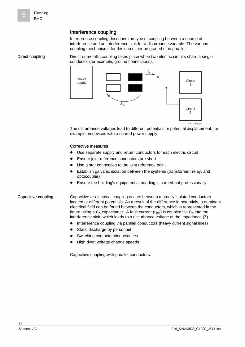
5 PlanningEMC
64Siemens AG 016_SINAMICS_G120P_J5111en
Interference couplingInterference coupling describes the type of coupling between a source ofinterference and an interference sink for a disturbance variable. The variouscoupling mechanisms for this can either be graded or in parallel.
Direct or metallic coupling takes place when two electric circuits share a singleconductor (for example, ground connections).
UInt
Powersupply Circuit
1
Circuit2
5192Z56en_02
The disturbance voltages lead to different potentials or potential displacement, forexample, in devices with a shared power supply.
Corrective measuresl Use separate supply and return conductors for each electric circuitl Ensure joint reference conductors are shortl Use a star connection to the joint reference pointl Establish galvanic isolation between the systems (transformer, relay, and
optocoupler)l Ensure the building's equipotential bonding is carried out professionally
Capacitive or electrical coupling occurs between mutually isolated conductorslocated at different potentials. As a result of the difference in potentials, a dominantelectrical field can be found between the conductors, which is represented in thefigure using a CK capacitance. A fault current (IStör) is coupled via CK into theinterference sink, which leads to a disturbance voltage at the impedance (Z).l Interference coupling via parallel conductors (heavy current signal lines)l Static discharge by personnell Switching contactors/inductancesl High dv/dt voltage change speeds
Capacitive coupling with parallel conductors:
Direct coupling
Capacitive coupling

Planning 5EMC
65Siemens AG 016_SINAMICS_G120P_J5111en
CK
Z
U1
U2
Circuit
IInt
5192
Z57e
n_02
The level of interference current is dependent on the size of the electrical field. Thestrength of the electrical field depends in turn on the potential difference and thedistance between the cables.
Corrective measuresThe simplest measure is to lay the cables and lines appropriately. The followingrules apply:l Increase the distance between the cablesl Lay motor cables separately to mains, control, and signal cables. When doing
so, use separate metallic and grounded cable channelsl Reduce the lengths of parallel cablesl If cables have to be crossed, do so with an angle of 90° as far as possiblel Use shielded cables with low capacitance for the motor cablesl Ensure the building's equipotential bonding is carried out professionally
Interference current flow:
CK
Z
U1
U2
Circuit 2
IInt51
92Z5
8en_
02
When using shielded signal lines and good shield connections, the interferencecurrent (IS) is grounded via the enclosure and has no effects on the internal electriccircuit. To shield against capacitive couplings, the cable shield only has to be laidon one side.
Inductive or magnetic coupling takes place between lines that carry current. Thealternating current that flows through the conductors generates a magnetic fieldthat induces a disturbance voltage in a neighboring conductor or in a conductorloop.
Inductive coupling

5 PlanningEMC
66Siemens AG 016_SINAMICS_G120P_J5111en
I
MK
U2 UInt
Circuit 2
5192
Z59e
n_02
The coupling is not affected by whether or not there is a direct connection betweenboth conductors. Typical sources of interference are:l Transformers, motors, electric welding devicesl Switching high currentsl High di/dt current changing speedl Signal lines with high frequency
Corrective measuresThe inductive and capacitive couplings co-exist between unshielded cables. Bothsides must be grounded when shielding against inductive influences. Be aware ofthe potential equalizing currents when grounding the shielding on both sides.Additional measures for reducing the interference:l Twist supply and return conductors and signal linesl Suppress contactorsl Increase the distance between the cables
Radiative coupling, also known as electromagnetic coupling, is the interactionbetween inductive and capacitive coupling in the form of a radiatedelectromagnetic field.Typical sources of interference are:l Neighboring senders (for example, mobile communication devices)l High-frequency appliancesl Spark gaps in devices (such as spark plugs and welding devices)
Corrective measuresEssentially, the same measures as listed previously also apply in this case. Ensurethat the radiated electromagnetic fields are, for the most part, in the high-frequencyrange. Use suitable shielding materials and protective braided shields to ensure agood shield. Lay the "radiating" cables as close to the ground plane as possible,i.e. reduce the effective antenna height.Inductances (such as contactor, relay, and solenoid valve coils) caused by currentand/or voltage peaks can lead to problems when operating the variable speeddrive, particularly if they are operating on the same network as the G120P.
In such cases, the appropriate windings for the contactors and relays operated onthe AC network must be reduced by quenching elements in the form of an RCseries connection or a varistor.
Radiative coupling
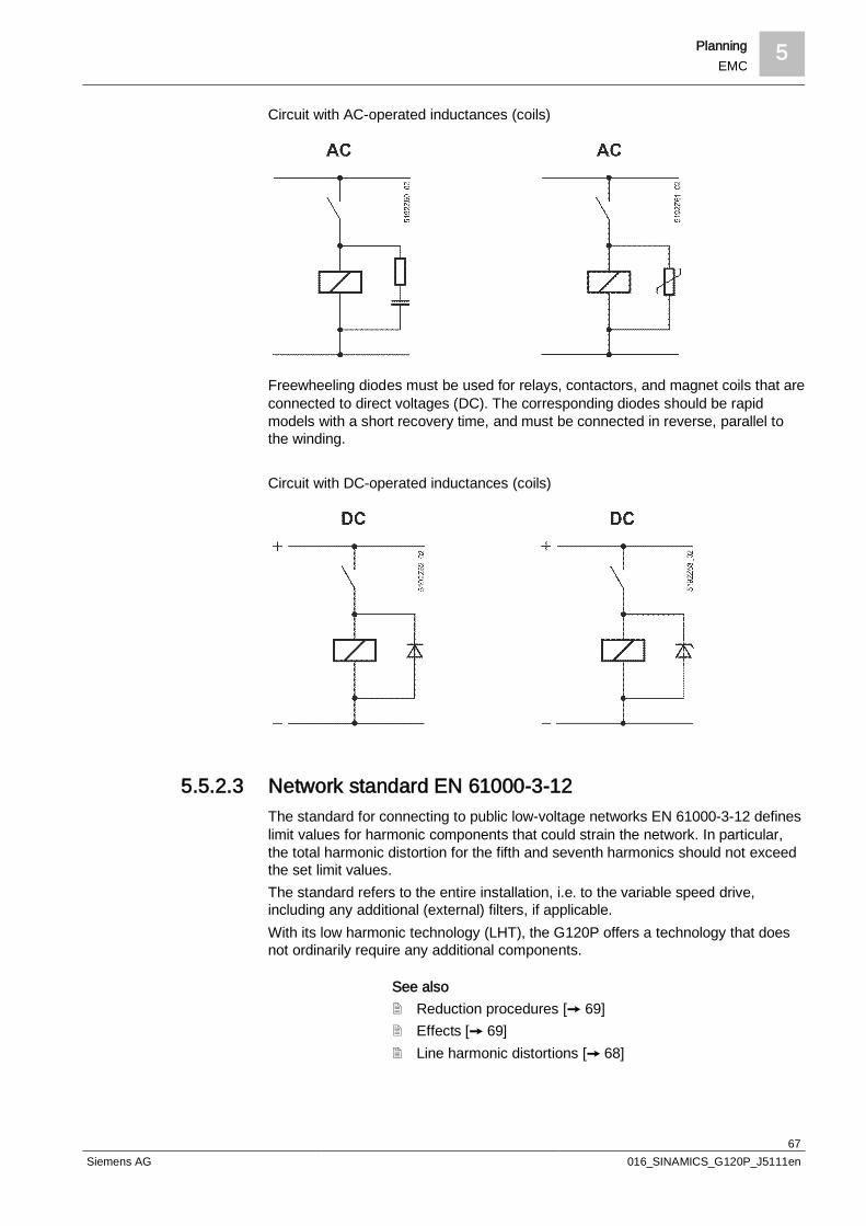
Planning 5EMC
67Siemens AG 016_SINAMICS_G120P_J5111en
Circuit with AC-operated inductances (coils)
Freewheeling diodes must be used for relays, contactors, and magnet coils that areconnected to direct voltages (DC). The corresponding diodes should be rapidmodels with a short recovery time, and must be connected in reverse, parallel tothe winding.
Circuit with DC-operated inductances (coils)
5.5.2.3 Network standard EN 61000-3-12The standard for connecting to public low-voltage networks EN 61000-3-12 defineslimit values for harmonic components that could strain the network. In particular,the total harmonic distortion for the fifth and seventh harmonics should not exceedthe set limit values.The standard refers to the entire installation, i.e. to the variable speed drive,including any additional (external) filters, if applicable.With its low harmonic technology (LHT), the G120P offers a technology that doesnot ordinarily require any additional components.
See also2 Reduction procedures [ 69]2 Effects [ 69]2 Line harmonic distortions [ 68]
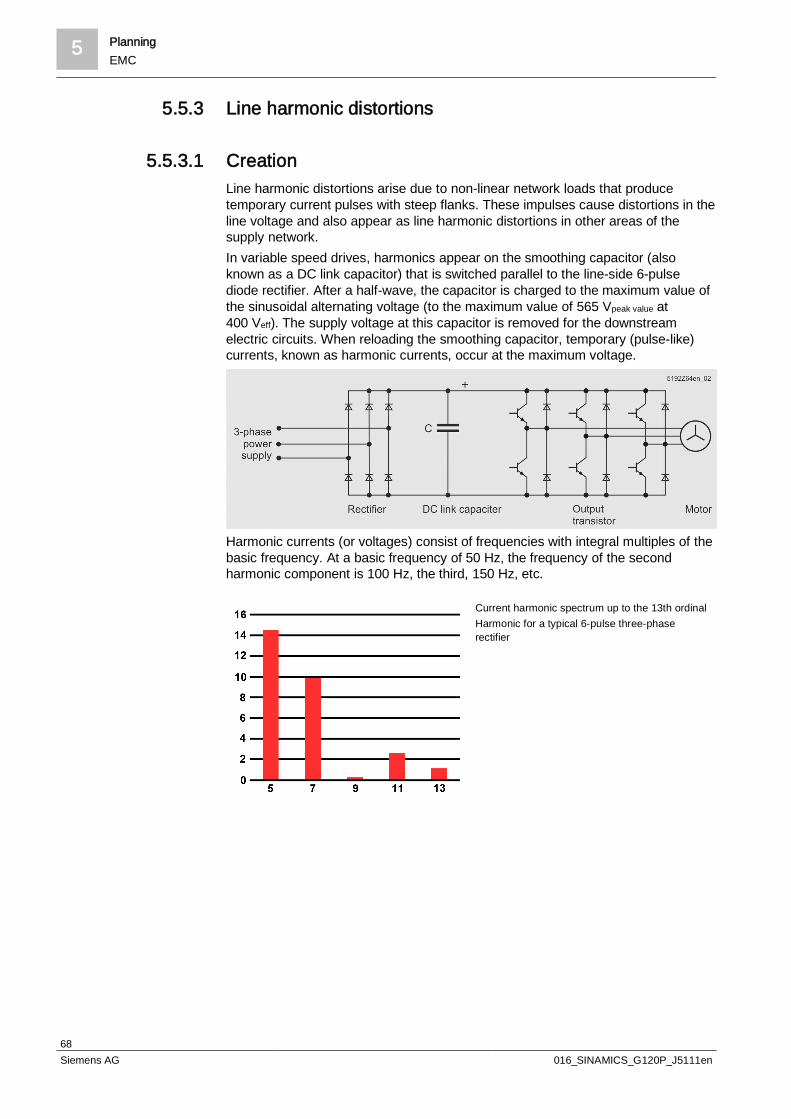
5 PlanningEMC
68Siemens AG 016_SINAMICS_G120P_J5111en
5.5.3 Line harmonic distortions
5.5.3.1 CreationLine harmonic distortions arise due to non-linear network loads that producetemporary current pulses with steep flanks. These impulses cause distortions in theline voltage and also appear as line harmonic distortions in other areas of thesupply network.In variable speed drives, harmonics appear on the smoothing capacitor (alsoknown as a DC link capacitor) that is switched parallel to the line-side 6-pulsediode rectifier. After a half-wave, the capacitor is charged to the maximum value ofthe sinusoidal alternating voltage (to the maximum value of 565 Vpeak value at400 Veff). The supply voltage at this capacitor is removed for the downstreamelectric circuits. When reloading the smoothing capacitor, temporary (pulse-like)currents, known as harmonic currents, occur at the maximum voltage.
Harmonic currents (or voltages) consist of frequencies with integral multiples of thebasic frequency. At a basic frequency of 50 Hz, the frequency of the secondharmonic component is 100 Hz, the third, 150 Hz, etc.
Current harmonic spectrum up to the 13th ordinalHarmonic for a typical 6-pulse three-phaserectifier
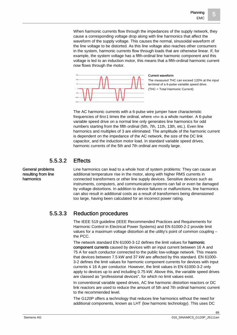
Planning 5EMC
69Siemens AG 016_SINAMICS_G120P_J5111en
When harmonic currents flow through the impedances of the supply network, theycause a corresponding voltage drop along with line harmonics that affect thewaveform of the supply voltage. This causes the normal, sinusoidal waveform ofthe line voltage to be distorted. As this line voltage also reaches other consumersin the system, harmonic currents flow through loads that are otherwise linear. If, forexample, the system voltage has a fifth-ordinal line harmonic component and thisvoltage is led to an induction motor, this means that a fifth-ordinal harmonic currentnow flows through the motor.
Current waveformThe measured THC can exceed 120% at the inputterminal of a 6-pulse variable speed drive.(THC = Total Harmonic Current)
The AC harmonic currents with a 6-pulse wire jumper have characteristicfrequencies of 6n±1 times the ordinal, where «n» is a whole number. A 6-pulsevariable speed drive on a normal line only generates line harmonics for oddnumbers starting from the fifth ordinal (5th, 7th, 11th, 13th, etc.). Even lineharmonics and multiples of 3 are eliminated. The amplitude of the harmonic currentis dependent on the impedance of the AC network, the size of the DC linkcapacitor, and the induction motor load. In standard variable speed drives,harmonic currents of the 5th and 7th ordinal are mostly large.
5.5.3.2 EffectsLine harmonics can lead to a whole host of system problems: They can cause anadditional temperature rise in the motor, along with higher RMS currents inconnected transformers or other line supply devices. Sensitive devices such asinstruments, computers, and communication systems can fail or even be damagedby voltage distortions. In addition to device failures or malfunctions, line harmonicscan also result in additional costs as a result of transformers being dimensionedtoo large, having been calculated for an incorrect power rating.
5.5.3.3 Reduction proceduresThe IEEE 519 guideline (IEEE Recommended Practices and Requirements forHarmonic Control in Electrical Power Systems) and EN 61000-2-2 provide limitvalues for a maximum voltage distortion at the utility's point of common coupling –the PCC.The network standard EN 61000-3-12 defines the limit values for harmoniccomponent currents caused by devices with an input current between 16 A and75 A for each conductor connected to the public low-voltage network. This meansthat devices between 7.5 kW and 37 kW are affected by this standard. EN 61000-3-2 defines the limit values for harmonic component currents for devices with inputcurrents ≤ 16 A per conductor. However, the limit values in EN 61000-3-2 onlyapply to devices up to and including 0.75 kW. Above this, the variable speed drivesare classed as "professional devices", for which no limit values exist.In conventional variable speed drives, AC line harmonic distortion reactors or DClink reactors are used to reduce the amount of 5th and 7th ordinal harmonic currentto the recommended level.The G120P offers a technology that reduces line harmonics without the need foradditional components, known as LHT (low harmonic technology). This uses DC
General problemsresulting from lineharmonics
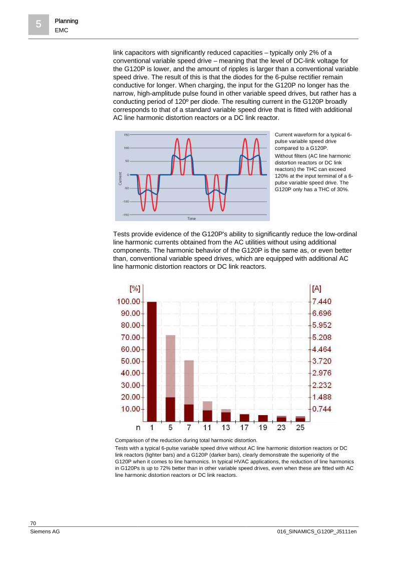
5 PlanningEMC
70Siemens AG 016_SINAMICS_G120P_J5111en
link capacitors with significantly reduced capacities – typically only 2% of aconventional variable speed drive – meaning that the level of DC-link voltage forthe G120P is lower, and the amount of ripples is larger than a conventional variablespeed drive. The result of this is that the diodes for the 6-pulse rectifier remainconductive for longer. When charging, the input for the G120P no longer has thenarrow, high-amplitude pulse found in other variable speed drives, but rather has aconducting period of 120º per diode. The resulting current in the G120P broadlycorresponds to that of a standard variable speed drive that is fitted with additionalAC line harmonic distortion reactors or a DC link reactor.
Current waveform for a typical 6-pulse variable speed drivecompared to a G120P.Without filters (AC line harmonicdistortion reactors or DC linkreactors) the THC can exceed120% at the input terminal of a 6-pulse variable speed drive. TheG120P only has a THC of 30%.
Tests provide evidence of the G120P's ability to significantly reduce the low-ordinalline harmonic currents obtained from the AC utilities without using additionalcomponents. The harmonic behavior of the G120P is the same as, or even betterthan, conventional variable speed drives, which are equipped with additional ACline harmonic distortion reactors or DC link reactors.
Comparison of the reduction during total harmonic distortion.Tests with a typical 6-pulse variable speed drive without AC line harmonic distortion reactors or DClink reactors (lighter bars) and a G120P (darker bars), clearly demonstrate the superiority of theG120P when it comes to line harmonics. In typical HVAC applications, the reduction of line harmonicsin G120Ps is up to 72% better than in other variable speed drives, even when these are fitted with ACline harmonic distortion reactors or DC link reactors.
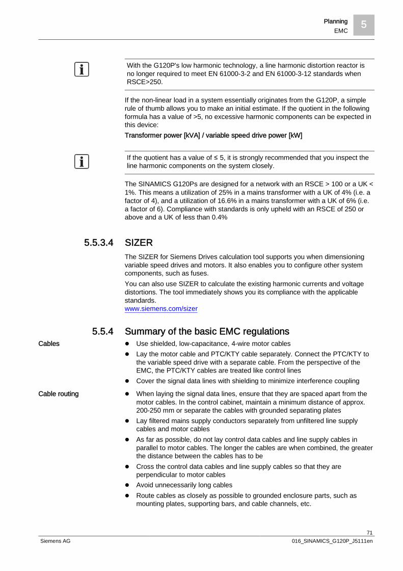
Planning 5EMC
71Siemens AG 016_SINAMICS_G120P_J5111en
With the G120P's low harmonic technology, a line harmonic distortion reactor isno longer required to meet EN 61000-3-2 and EN 61000-3-12 standards whenRSCE>250.
If the non-linear load in a system essentially originates from the G120P, a simplerule of thumb allows you to make an initial estimate. If the quotient in the followingformula has a value of >5, no excessive harmonic components can be expected inthis device:Transformer power [kVA] / variable speed drive power [kW]
If the quotient has a value of ≤ 5, it is strongly recommended that you inspect theline harmonic components on the system closely.
The SINAMICS G120Ps are designed for a network with an RSCE > 100 or a UK <1%. This means a utilization of 25% in a mains transformer with a UK of 4% (i.e. afactor of 4), and a utilization of 16.6% in a mains transformer with a UK of 6% (i.e.a factor of 6). Compliance with standards is only upheld with an RSCE of 250 orabove and a UK of less than 0.4%
5.5.3.4 SIZERThe SIZER for Siemens Drives calculation tool supports you when dimensioningvariable speed drives and motors. It also enables you to configure other systemcomponents, such as fuses.You can also use SIZER to calculate the existing harmonic currents and voltagedistortions. The tool immediately shows you its compliance with the applicablestandards.www.siemens.com/sizer
5.5.4 Summary of the basic EMC regulationsl Use shielded, low-capacitance, 4-wire motor cablesl Lay the motor cable and PTC/KTY cable separately. Connect the PTC/KTY to
the variable speed drive with a separate cable. From the perspective of theEMC, the PTC/KTY cables are treated like control lines
l Cover the signal data lines with shielding to minimize interference coupling
l When laying the signal data lines, ensure that they are spaced apart from themotor cables. In the control cabinet, maintain a minimum distance of approx.200-250 mm or separate the cables with grounded separating plates
l Lay filtered mains supply conductors separately from unfiltered line supplycables and motor cables
l As far as possible, do not lay control data cables and line supply cables inparallel to motor cables. The longer the cables are when combined, the greaterthe distance between the cables has to be
l Cross the control data cables and line supply cables so that they areperpendicular to motor cables
l Avoid unnecessarily long cablesl Route cables as closely as possible to grounded enclosure parts, such as
mounting plates, supporting bars, and cable channels, etc.
Cables
Cable routing

5 PlanningEMC
72Siemens AG 016_SINAMICS_G120P_J5111en
l Lay the signal lines and accompanying equipotential-bonding cable as closelyas possible to each other
l Ground spare cores at both ends. This achieves an additional shielding effectl Whenever possible, route signal lines/data cables into the cabinet on one side
only (from the bottom only, for example)l Ensure signal lines, particularly reference value and actual value lines, are laid
free of interruptions. Ensure that the shielding connection is continuous atseparation points
l Foil shields are not suitable. This is because they are at least 5 times lesseffective than braided shields.
l Lay the cable shields directly onto a busbar from the cable's point of entry intothe cabinet and continue to route it from here
l The shields must be grounded with good conductivity on both sides over alarge area. They must also be connected to the grounded enclosures withsurface conductivity. This is the only way to make them effective againstelectromagnetic interference
l To fix the protective braided shields, it is best to use metal cleats. The cableclamps must connect the shield over a large area and make good contact
l Do not leave any gaps in the shieldl Only use metallic or metalized connector enclosures at the plug-in connections
for shielded cables
l Use equipotential-bonding cables that have been appropriately dimensioned(with a cross-section of at least 16 mm2 CU) to avoid potential differencesbetween devices
l Connect all equipotential-bonding cables in the control cabinet on the centralgrounding bar or on a separate, low resistance, grounded potential equalizingbar
l Use flat ribbon cables to establish a ground connection for devices
5.5.5 EMC-compliant installationWithout interference suppression measures, variable speed drives send outpermanent interfering signals. These interfering signals can cause the followingproblems in the area surrounding the device:l Analog signal errors, for example in sensors, resulting in falsified measured
valuesl Sporadic faultsl Unstable controlsl Errors in other devices in the vicinity of the variable speed drivel Interference from communication devices
To ensure safe, reliable, and trouble-free operation, the devices must beprofessionally installed, and the following interference suppression measures mustbe followed in the context of EMC:
An overview of control cabinet configuration and cabling, along with information onhow to connect the variable speed drive, can be found in the following sections.You will find further details in the installation instructions for the Power Module.
Shield
Equipotential bonding

Planning 5EMC
73Siemens AG 016_SINAMICS_G120P_J5111en
Variable speed drives with degree of protection IP20 must be installed andoperated in an EMC-compatible control cabinet.Variable speed drives with degree of protection IP55 can also installed outside acontrol cabinet.
5.5.6 EMC-compliant designThe cheapest way to suppress interference is to keep sources of interferenceseparate from interference sinks, so bear this in mind in the planning phase.You should divide the devices in use into potential sources of interference orinterference sinks:l In this context, variable speed drives, braking modules, and contactors, for
example, can be counted as sources of interferencel Examples of interference sinks include PLCs, encoders, and sensorsThe entire drive system then has to be divided into EMC zones with the devicesassigned to these zones. The zone concept is clarified in the following diagram:
Zone A Mains connection limit values for the conducted interference emissions and interferenceimmunity must be observed
Zone B Power electrics/electronics, potential sources of interferenceZone C Control/sensor technology, potential interference sinks
Zone D Periphery/interface limit values for the interference immunity must be observedZone E Power electrics/electronics, potential sources of interference-- -- -- Grounded separating plates
Specific requirements regarding the interference emission and the interferenceimmunity apply within each zone. Separate the zones, ideally using metal housingor, within a control cabinet, using grounded separating plates. Filters may have to

5 PlanningEMC
74Siemens AG 016_SINAMICS_G120P_J5111en
be installed at the zone interfaces. Route cables from the various zonesseparately/shielded from each other.
5.5.6.1 Control cabinet designCorrect installation of the control cabinet components (controllers, contactors,display elements, variable speed drive, etc.) produces significant protection againstinternal/external disturbance variables. The essential points in this regard are touse conductive materials, establish good contact and connections for all enclosureparts, and avoid large openings in the cabinet walls. Special EMC cabinets can beinstalled in the case of particularly large shielding attenuation requirements.It is possible to avoid unacceptable mutual interference by installing thecomponents properly within the control cabinet in the defined EMC zones. Thecorrect cable routing and shielding treatment are also crucial.For a standard version control cabinet made of coated sheet steel, good shieldingattenuation can be achieved by following a few simple rules. The fundamentalprinciple is to install the control cabinet as a Faraday cage.l Conventional aluminum or steel control cabinets with a tightly screwed
mounting grate generally have the required ground connections. Thenecessary ground connections are provided in the basic version.
l Connect all the metallic parts and components of the control cabinet (sideplates, rear panels, cover and base plates) to the frame of the cabinet with agood electrical connection. The best way to achieve this is by using the largestpossible contact surface, a variety of individual screwed connections, orextensive connections through wide grounding straps.
l Connect the PE busbar and EMC shielding bus to the control cabinet frameusing a strong electrical connection produced with the largest possible surfacearea.
l Connect all metal enclosures for the devices and the additional componentsinstalled in the control cabinet (such as the variable speed drive or line filter) tothe control cabinet frame via a strong electrical connection and the largestpossible surface area. The most effective way to set this out is to install thedevices and additional components on a blank, highly conductive metal plate,which, in turn, is connected to the control cabinet frame via a strong electricalconnection and the largest possible surface area. It is particularly crucial toconnect them to the PE busbar and EMC shielding bus.
l All connections must be made durable. Screwed connections with painted or anodized metal components must eitherbe made with special (toothed) contact washers that cut through the insulatingsurface to make contact with a metal conductor, or else the insulating surfacemust be removed from the contact points.
l The material of the components to be connected, including the connectionelements (screws, toothed lock washer, rivets, etc.), should be positioned closeto each other in the electrochemical series.
l Coils of contactors, relays, solenoid valves, and motor holding brakes must beequipped with interference suppressors in order to dampen high-frequencyradiation when switching-off (RC elements or varistors with AC coils and free-wheeling diodes or varistors for DC coils). Connect the protective circuit directlyto the coil.
Gaps in the control cabinet wallThe shielding effect of the control cabinet is deteriorated by adding ventilationholes, inspection windows, and operator controls, etc. Each opening with the size

Planning 5EMC
75Siemens AG 016_SINAMICS_G120P_J5111en
of half of the wavelength λ of the interference frequency functions as an antennaand radiates electromagnetic fields. In practice, the slit lengths should be less thanλ/20.
Offset holes or HF grids are generally better as ventilation openings than slits are.Lots of small holes are more effective than a few large ones.
When installing operator controls and operator panels, ensure that the metallicinstallation frames have good all-round contact. Otherwise, EMC seals or coversmay have to be installed.
The best way to ground shields is to use cable entries that have good all-roundcontact with the shield and an HF-proof connection with the enclosure (cabinetwall). This prevents interference fields that arise in the cabinet from being radiatedoutwards via the shielded cable. For this reason, ensure that there is goodconductivity when connecting the outer shield at the control cabinet entry point forall shielded cables to the cabinet enclosure.
The shielding, equipotential bonding, and protective conductor busbars areconnected to the control cabinet ground. Inside the control cabinet, they have thesame reference potential.Shields carry interference currents to reduce unwanted mutual influences. Thepurpose of the shielding busbar is to lay the cable shields when entering the cablesinto the control cabinet. Its connection with the shared control cabinet ground(mounting plate) must be large in surface area, high frequency, and low resistance.Protective conductors (PE, protective earth) only carry current in the event of afault. The central protective conductor busbar must be connected to the groundingbar. The central grounding bar must have a conductive connection with the controlcabinet ground (metal-metal connection). This is the only way for fault andinterference currents to be safely discharged.Under normal operating conditions, reference conductors (neutral conductors,switching ground, 0 V) carry current.The protective and reference conductors must be dimensioned according to therelevant standards and guidelines.The grounding, protective conductor, and shielding concepts must be compatiblewith each other to ensure that unwanted potential displacement/interferencecurrents are avoided.For optimal EMC, perform consistent low and high-frequency equipotential bondingwith good conductivity for all metallic enclosures, cabinets, machines, and devices.
5.5.7 EMC-compliant wiringl Use a shielded cable for the motor. The shield should have the lowest possible
HF impedance and must not contain any gaps.l For signal, control and data cables, only use shielded cables with twisted wires.l Keep the HF contact resistance as low as possible at the connection points
between the shield and enclosure.l Ground the shields for motor and control cables on both sides using EMC cable
glands (EMC fittings, EMC cable clamps, EMC terminals, or similar) toestablish a good 360° contact with the shield.
l Avoid high equalizing currents in the shields by establishing a connection withthe lowest possible resistance (min. 16 mm2 Cu) and impedance between thevariable speed drive enclosure and the ground (equipotential busbar).
l Connect the return ground of the motor controlled by the variable speed drivedirectly at the ground terminal (PE) of the associated variable speed drive.
Ventilation slits
Control elements
Cable entries
Shielding, equipotentialbonding, and protectiveconductor busbars

5 PlanningEMC
76Siemens AG 016_SINAMICS_G120P_J5111en
l Avoid loops in the cables. Ensure that all devices are connected to the supplywith star grounding.
Use flexible grounding straps to connectmoving parts (e.g. cabinet doors and swingframes).In the event of a fault, the ground must nottake on any dangerous touch voltages, andmust be grounded to avoid this occurring.Avoid grounding loops.
Grounded cabinet door:
5.5.7.1 Cable routing in the control cabinetAlways route power cables and signal lines separately. For this purpose, thevarious cables are arranged according to cable groups. Cables belonging to agroup can be combined in a bundle. Lay the various cable groups with thenecessary distance between them.l Whenever possible, route signal lines/ data cables into the cabinet at one point
onlyl Route all cables inside the control cabinet so that they are always as close as
possible to mechanical enclosure parts, for example, control cabinet walls,mounting plates, supporting bars, and metal bars. Laying cables in free spaceleads to increased interference coupling and radiation (antenna effect)
l Lay associated cables (supply and return conductors) togetherl Lay all variable speed drive power cables (line supply cables and motor cables)
so that they are spaced apart from signal and data cables. The minimumclearance is approximately 25 cm. Alternatively, the decoupling in the controlcabinet can be established by means of metal barriers that are connecting tothe mounting plate via a good electrical connection
l Ensure that the cables from the line supply to the line filter are routedseparately from non-filtered power cables with a high interference level, forexample cables between the line filter and variable speed drive, connectingcables between the braking chopper and the associated braking resistor aswell as motor cables
l Route control circuits for contacts (230 VAC) as far as possible from signallines
l Only cross signal and data cables, as well as filtered line supply cables, at rightangles to unfiltered power cables
l Keep all lines as short as possiblel Always lay signal lines, data cables, and the associated potential equalizing
cables in parallel with the smallest possible distance between them
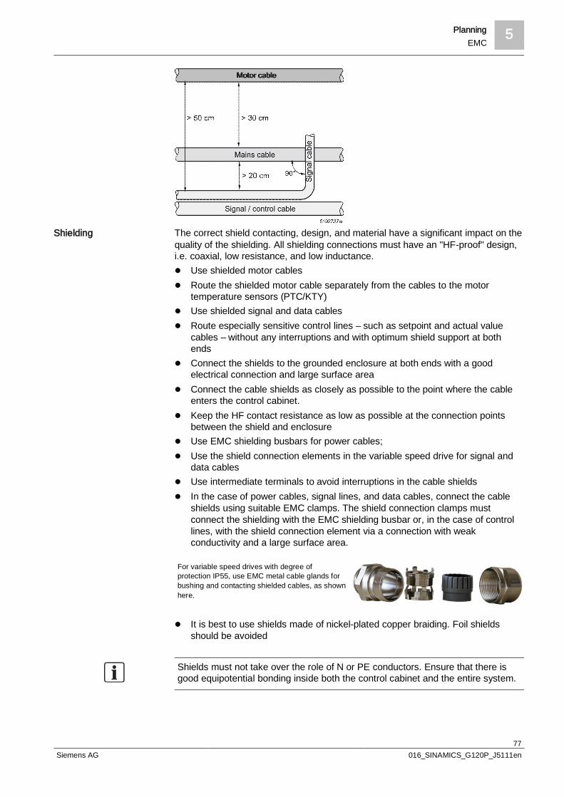
Planning 5EMC
77Siemens AG 016_SINAMICS_G120P_J5111en
The correct shield contacting, design, and material have a significant impact on thequality of the shielding. All shielding connections must have an "HF-proof" design,i.e. coaxial, low resistance, and low inductance.l Use shielded motor cablesl Route the shielded motor cable separately from the cables to the motor
temperature sensors (PTC/KTY)l Use shielded signal and data cablesl Route especially sensitive control lines – such as setpoint and actual value
cables – without any interruptions and with optimum shield support at bothends
l Connect the shields to the grounded enclosure at both ends with a goodelectrical connection and large surface area
l Connect the cable shields as closely as possible to the point where the cableenters the control cabinet.
l Keep the HF contact resistance as low as possible at the connection pointsbetween the shield and enclosure
l Use EMC shielding busbars for power cables;l Use the shield connection elements in the variable speed drive for signal and
data cablesl Use intermediate terminals to avoid interruptions in the cable shieldsl In the case of power cables, signal lines, and data cables, connect the cable
shields using suitable EMC clamps. The shield connection clamps mustconnect the shielding with the EMC shielding busbar or, in the case of controllines, with the shield connection element via a connection with weakconductivity and a large surface area.
For variable speed drives with degree ofprotection IP55, use EMC metal cable glands forbushing and contacting shielded cables, as shownhere.
l It is best to use shields made of nickel-plated copper braiding. Foil shieldsshould be avoided
Shields must not take over the role of N or PE conductors. Ensure that there isgood equipotential bonding inside both the control cabinet and the entire system.
Shielding

5 PlanningEMC
78Siemens AG 016_SINAMICS_G120P_J5111en
Do not use pigtails (wire shield extensions to theterminal) to connect shields
5.5.7.2 Cable routing outside the control cabinetEnsure that there is as much space as possible between the signal and powercables. If it is not possible to establish a large enough distance between them, useshielded cables in protective, grounded cable channels made of metal.l Lay signal, control, and data cables free of interruptionsl Ensure that there is a continuous shield connection to cable separating points
for shielded cablesl Ground the shields for motor and control cables on both sides using EMC cable
glands (EMC fittings, EMC cable clamps, EMC terminals, or similar) toestablish a good 360° contact with the shield
l Avoid high equalizing currents in the shields by establishing a connection withthe lowest possible resistance (min. 16 mm2 Cu) and impedance between thevariable speed drive enclosure and the ground (equipotential busbar)
l Lay the motor cable so that it is as short as possible, generally less than 25 m,see Section Motor connection cable [ 85]
l Lay cables on metallic, grounded cable holders or in cable channels
If it is not possible to feed control, supply, and motor cables intoseparate cable channels or holders, the cable channel/holdermust at least have metallic, electrically conductive separatorsthroughout.
l The longer the cables are when combined, the greater the distance betweenthe cables has to be
l Connect the cable holder's intersection points with each other over a large areaand with good electrical connectivity
l Twist unshielded cables from the same electric circuit (supply and returnconductors) or ensure that the surface area between the supply and returnconductors is as small as possible
l Lay the signal lines and accompanying equipotential-bonding cable as closelyas possible to each other
l Signal lines must not pass devices that generate strong magnetic fields, suchas motors and transformers

Planning 5EMC
79Siemens AG 016_SINAMICS_G120P_J5111en
l Connect the return ground of the motor controlled by the variable speed drivedirectly at the ground connection (PE) of the associated variable speed drive.We recommend the use of 4-wire motor cables. The G120P's motorplugs/terminals have four connections
l Avoid loops in the cablesl Ensure that all devices are connected to the supply with star groundingl Avoid unnecessary cable lengths, even for spare cablesl Complete the internal and external lightning protection and grounding
measures according to the applicable standards
5.5.7.3 EMC-compliant wiring for Power Modules with degree ofprotection IP20Using two examples, the following diagram shows the EMC-compliant installationof Power Modules with and without a shield plate.
The display in the following diagram is not to scale. The terminal cover cannot beremoved. It was only taken out of the diagram to better show the cableconnection.
Without shield plate With shield plate
1 Mains connection 7 Steel band2 Motor connection 8 Cable tie3 Line supply cable (unshielded) 9 Metal mounting plate (unpainted and with a
good electrical conductivity)4 Motor connection cable (shielded) 10 Shield plate (optional)
5 Cable shield
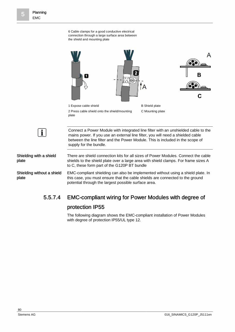
5 PlanningEMC
80Siemens AG 016_SINAMICS_G120P_J5111en
6 Cable clamps for a good conductive electricalconnection through a large surface area betweenthe shield and mounting plate
1 Expose cable shield B Shield plate2 Press cable shield onto the shield/mountingplate
C Mounting plate
Connect a Power Module with integrated line filter with an unshielded cable to themains power. If you use an external line filter, you will need a shielded cablebetween the line filter and the Power Module. This is included in the scope ofsupply for the bundle.
There are shield connection kits for all sizes of Power Modules. Connect the cableshields to the shield plate over a large area with shield clamps. For frame sizes Ato C, these form part of the G120P BT bundle
EMC-compliant shielding can also be implemented without using a shield plate. Inthis case, you must ensure that the cable shields are connected to the groundpotential through the largest possible surface area.
5.5.7.4 EMC-compliant wiring for Power Modules with degree ofprotection IP55The following diagram shows the EMC-compliant installation of Power Moduleswith degree of protection IP55/UL type 12.
Shielding with a shieldplate
Shielding without a shieldplate

Planning 5EMC
81Siemens AG 016_SINAMICS_G120P_J5111en
You must use a shielded cable if you use the control terminals of the Control Unit.The cable shield must be connected to the gland plate through a good electricalconnection using an EMC gland. If a standard gland is used, the shield must belaid on the CU's shield connection kit.
In devices with filter B, it is essential to use an EMC gland to achieve maximumshielding. The shield must be fed through the EMC shield and then laid separatelyagain on the gland plate.
5.5.7.5 Cable gland plate in IP55 modelsA cable gland plate with pre-drilled cable glands can be found on the bottom of thevariable speed drive enclosure. This plate allows you to route the line supply andcontrol cable out of the device and, at the same time, meet the requirements ofboth EMC and degree of protection IP55/UL type 12.The following figures display the cable gland plate as well as its fixing points.Plug unused cable glands with a rubber sleeve to ensure that the cable gland plateis sealed.When re-fitting the gland plate, ensure that the seal on the bottom of the device isattached correctly and that the correct tightening torques are observed, otherwisethe variable speed drive does not fulfill the degree of protection IP55.
Overview

5 PlanningEMC
82Siemens AG 016_SINAMICS_G120P_J5111en
FSA to FSC gland plates
FSD to FSF gland plates
The following table provides the gland plate drilling dimensions for all frame sizesof the PM230. Rubber sleeves are included in the scope of supply for the product.The cable glands are not included in the scope of supply. To ensure the variablespeed drive is protected in accordance with degree of protection IP55, dimensionthe cable glands so that they fit into the corresponding holes with ease.
Frame size Power range (LO) Diameter of power supplycable gland
Diameter of control cablegland
A 0.37 to 3.0 kW(0.5 to 4.0 PS)
20.5 mm(0.80 inches)
20.5 mm(0.80 inches)
B 4.0 to 7.5 kW(5.0 to 10.0 PS)
25.5 mm(1.0 inches)
20.5 mm(0.80 inches)
C C 11.0 to 18.5 kW(14.0 to 24.0 PS)
32.5 mm(1.27 inches)
20.5 mm(0.80 inches)
D D 22.0 to 30.0 kW(29.0 to 40.0 PS)
40.5 mm(1.59 inches)
20.5 mm(0.80 inches)
Drilling dimensions forthe gland plate
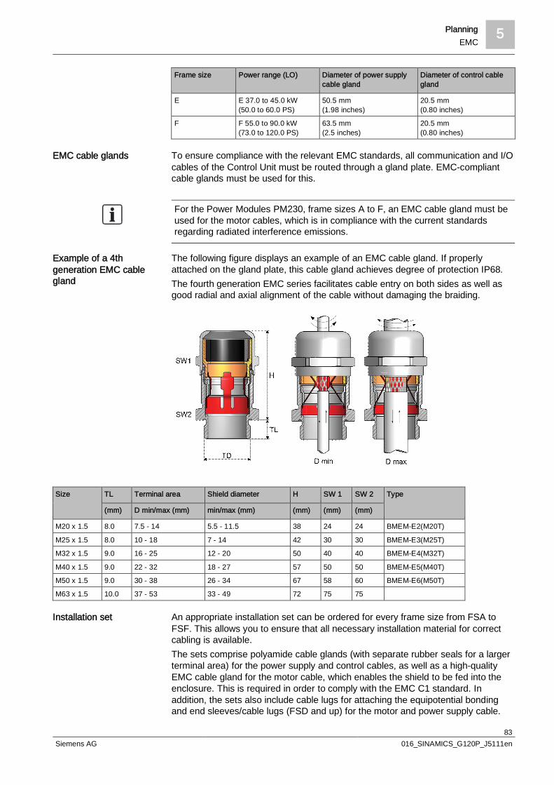
Planning 5EMC
83Siemens AG 016_SINAMICS_G120P_J5111en
Frame size Power range (LO) Diameter of power supplycable gland
Diameter of control cablegland
E E 37.0 to 45.0 kW(50.0 to 60.0 PS)
50.5 mm(1.98 inches)
20.5 mm(0.80 inches)
F F 55.0 to 90.0 kW(73.0 to 120.0 PS)
63.5 mm(2.5 inches)
20.5 mm(0.80 inches)
To ensure compliance with the relevant EMC standards, all communication and I/Ocables of the Control Unit must be routed through a gland plate. EMC-compliantcable glands must be used for this.
For the Power Modules PM230, frame sizes A to F, an EMC cable gland must beused for the motor cables, which is in compliance with the current standardsregarding radiated interference emissions.
The following figure displays an example of an EMC cable gland. If properlyattached on the gland plate, this cable gland achieves degree of protection IP68.The fourth generation EMC series facilitates cable entry on both sides as well asgood radial and axial alignment of the cable without damaging the braiding.
Size TL Terminal area Shield diameter H SW 1 SW 2 Type
(mm) D min/max (mm) min/max (mm) (mm) (mm) (mm)
M20 x 1.5 8.0 7.5 - 14 5.5 - 11.5 38 24 24 BMEM-E2(M20T)
M25 x 1.5 8.0 10 - 18 7 - 14 42 30 30 BMEM-E3(M25T)
M32 x 1.5 9.0 16 - 25 12 - 20 50 40 40 BMEM-E4(M32T)
M40 x 1.5 9.0 22 - 32 18 - 27 57 50 50 BMEM-E5(M40T)
M50 x 1.5 9.0 30 - 38 26 - 34 67 58 60 BMEM-E6(M50T)
M63 x 1.5 10.0 37 - 53 33 - 49 72 75 75
An appropriate installation set can be ordered for every frame size from FSA toFSF. This allows you to ensure that all necessary installation material for correctcabling is available.The sets comprise polyamide cable glands (with separate rubber seals for a largerterminal area) for the power supply and control cables, as well as a high-qualityEMC cable gland for the motor cable, which enables the shield to be fed into theenclosure. This is required in order to comply with the EMC C1 standard. Inaddition, the sets also include cable lugs for attaching the equipotential bondingand end sleeves/cable lugs (FSD and up) for the motor and power supply cable.
EMC cable glands
Example of a 4thgeneration EMC cablegland
Installation set

5 PlanningEMC
84Siemens AG 016_SINAMICS_G120P_J5111en
You can find the available installation sets and their order numbers in SectionAccessories [ 30].A set contains the following components:
FSA FSB FSC FSD FSE FSF
Brass EMC cable gland for motorcables incl. EMC lock nuts
1 x M20x1.5 1 x M25x1.5 1 x M32x1.5 1 x M40x1.5 1 x M50x1.5 1 x M63x1.5
Polyamide cable gland for powersupply cable incl. lock nuts
1 x M20x1.5Terminal area5-12 mm
1 x M25x1.5Terminal area8-17 mm
1 x M32x1.5Terminal area11-21 mm
1 x M40x1.5Terminal area16-28 mm
1 x M50x1.5Terminal area21-38 mm
1 x M63x1.5Terminal area27-44 mm
Polyamide cable gland for controllines incl. lock nuts
3 x M20x1.5Terminal area5-12 mm
3 x M20x1.5Terminal area5-12 mm
3 x M20x1.5Terminal area5-12 mm
4 x M20x1.5Terminal area5-12 mm
4 x M20x1.5Terminal area5-12 mm
4 x M20x1.5Terminal area5-12 mm
Cable lugs for equipotentialbonding
1 x Ø 10 mm2
1 xØ 16 mm2
1 x Ø 10 mm2
1 xØ 16 mm2
1 x Ø 10 mm2
1 xØ 16 mm2
1 xØ 16 mm2
1 xØ 16 mm2
1 xØ 16 mm2
End sleeves for power supply andmotor cables in accordance withDIN 46228 T 1
8 xØ 1 mm2
8 xØ 1.5 mm2
8 xØ 2.5 mm2
8 xØ 2.5 mm2
8 xØ 4 mm2
8 xØ 6 mm2
8 xØ 6 mm2
8 xØ 10 mm2
8 xØ 16 mm2
- - -
Cable lug for power supply andmotor cables
- - - 8 xØ 10 mm2
8 xØ 16 mm2
8 xØ 25 mm2
8 xØ 35 mm2
8 xØ 25 mm2
8 xØ 35 mm2
8 xØ 50 mm2
8 xØ 16 mm2
8 xØ 70 mm2
8 xØ 95 mm2
8 xØ 120 mm2
5.5.7.6 Equipotential bonding and groundingRoute all electrical components separately (with star grounding) to theequipotential bonding.For each variable speed drive, connect the enclosure for the IP55 device version –and the ground connection for the IP20 – to the central ground(grounding/equipotential busbar) via the shortest possible low-resistanceequipotential-bonding cable with low impedance.For equipotential-bonding cables, it is best to use flat, strap-shaped conductorsmade of tin-coated copper braiding or similar (min. cross-section 16 mm2), as thesehave a lower impedance at higher frequencies.
The conductors create the skin effect, which is stronger in conductors with around cross-section than those that are strap-shaped. The effect increases as thefrequency does, because the current density in the outer conductor range issignificantly higher than at the conductor core, as eddy currents cause the currentflow to decelerate in the conductor core.

Planning 5EMC
85Siemens AG 016_SINAMICS_G120P_J5111en
You should also connect each of the motors controlled by the variable speed driveto ground/the monoblock's grounding point using an equipotential-bonding cablewith a large cross-section.Connect all control devices that are connected to the variable speed drive (forexample, a BMS, BAS, or PLC) to the same ground or same grounding point as thevariable speed drive (equipotential busbar) using the shortest possibleequipotential-bonding cable.As the ground must not take on any dangerous touch voltages, even in the event ofa fault, it must be connected to ground using protective conductors.Avoid grounding loops.
The minimum required grounding conductor cross-section for the equipotentialbonding according to EN 61800-5-1 can be found in the following diagram:
p Cross-section of grounding conductor
I Cross-section of line conductor
5.5.7.7 Cables
Supply cableNo special cable types are required for the supply line. Ensure that the wire cross-section corresponds to the current to be fed. All cable manufacturers havestandard cables of 4 x n mm2.
Motor connection cableThe motor cables have a high interference intensity. To limit the emittedinterference, use shielded, low-capacitance, 4-wire motor cables (U, V, W, and PEwith shielding).
Groundingconductor/Line conductor
5.5.7.7.1
5.5.7.7.2

5 PlanningEMC
86Siemens AG 016_SINAMICS_G120P_J5111en
Cable types recommended by Siemens AG:
Manufacturer Description Type Scaling
Prysmian Protoflex EMC-FC 2YSLCY-J 0.6/1 kV DIN VDE 0250
Helukabel TOPFLEX® EMC-3 PLUS2YSLCY-J
2YSLCY-J 0.6/1 kV DIN VDE 0250
Lapp Kabel Ölflex Servo 2YSLCYK-JB 0.6/1 kV DIN VDE 0250
If you use cables made by other manufacturers, ensure that the type designationscorrespond. These describe the physical properties required for EMC-compliantoperation.
Conductor cross-sections for supply and motor cablesObserve the minimum cross-section requirements of the site supplying the energy.
Frame size Power (kW) Min. cross-sectionmm2 (AWG)
Max. cross-sectionmm2 (AWG)
A 0.37 1 (18) 2.5 (14)
0.55 1 (18) 2.5 (14)
0.75 1 (18) 2.5 (14)
1.1 1 (18) 2.5 (14)
1.5 1 (18) 2.5 (14)
2.2 1.5 (16) 2.5 (14)
3 1.5 (16) 2.5 (14)
B 4 2.5 (14) 6 (10)
5.5 4 (12) 6 (10)
7.5 4 (12) 6 (10)
C 11 6 (10) 16 (5)
15 10 (7) 16 (5)
18.5 10 (7) 16 (5)
D 22 16 (5) 35 (2)
30 25 (3) 35 (2)
E 37 25 (3) 50 (1/0)
45 35 (2) 50 (1/0)
F 55 70 (2/0) 120 (4/0)
75 95 (3/0) 120 (4/0)
90 95 (3/0) 120 (4/0)
Cable lengthsThe performance data according to the specifications is only valid if the motorcables do not exceed the following lengths:l 50 m for shielded cablesl 100 m for unshielded cables
5.5.7.7.2.1
Input voltage range 380to 480 VAC, 3-phase
5.5.7.7.2.2

Planning 5Filters
87Siemens AG 016_SINAMICS_G120P_J5111en
Longer motor cables can be used if output filters are inserted. For more informationin this regard, see the REO CNW 833 dv/dt filter and REO CNW 933 sine-wavefilter in Section Filter Overview [ 89].
Where several motors are connected to a variable speed drive, the motor cablelength is made up of the sum of all the individual motor cables.
Signal and data cablesTo minimize interference coupling, only use shielded cables to wire analog inputsand outputs and for communication conductors. The PTC and Klixon temperaturesensors must also be connected to the variable speed drive with a shielded cable.From the perspective of the EMC, the PTC/KTY cables are treated like controllines. For additional information, see Section EMC-compliant wiring [ 75].
5.6 Filters
5.6.1 Adapting the motor to the variable speed drive (outputfilter)Frequency-controlled three-phase asynchronous motors offer many advantages.However, supplying motors with non-sinusoidal currents and voltages from thevariable speed drive also places additional strain on the motors and pressure onthe overall drive and environment.These aspects must be observed when selecting the motor and configuring thedrive. The possible problems are defined below.
The problem essentially arises from the rapid switching operations in the variablespeed drive's Power Module. In variable speed drives with pulse width modulation(PWM), which also includes the G120P, the elementary frequency determines thequality of the interference emitted by the variable speed drive. This interferencecan spread, amongst other things, conducted as symmetrical or asymmetricalinterference currents, even via the motor cables. A proportion of the high frequencycurrent flows as leakage current, amongst other things, via the motor mount toground. In the case of unshielded motor cables, high interference fields can also begenerated (non-conducted interference). Shielded motor cables considerablyreduce the amount of this interference that is radiated.
A further problem lies in the rate of voltage rise for the motor voltages at thevariable speed drive output. With their short switching times, modern power unitswith IGBTs, such as those used in the G120P, achieve voltage pulse slew rates ofbetween 2 and 10 kV at the variable speed drive output. These voltage pulsespass along the motor cable between the variable speed drive and motor astravelling waves. These are reflected at the motor windings, which leads to highvoltage peaks at the motor connections.The excessive voltage peaks can reach double the value of the DC-link voltage,approx. 1,200 V for a 400 V line voltage, for example. These permanently highvoltage pulses lead to premature aging of the winding insulation. Nevertheless, thesupply for three-phase asynchronous motors via variable speed drives with DC-linkvoltages of up to 560 V for conventional motor insulations (standard motor) has nonegative effects on the service life.
5.5.7.7.3

5 PlanningFilters
88Siemens AG 016_SINAMICS_G120P_J5111en
If motors are used that are not insulated according to requirements, then outputfilters must be used.
Dv/dt filter Sine-wave filter
In summary, the following effects can arise when using the variable speed drive:l High-frequency reactive currents in the motor cablel Overvoltage at the motor caused by a high rate of voltage rise and a long motor
cablel Damage to the mount due to leakage currents in the motor mountl Motor noisesl EMC problemsl Damage to the motor insulation
If operating motors directly (without output filter) on a variable speed drive, pleaseobserve the following:l Motors for IGBT variable speed drives (pulse variable speed drives with the
same voltage-source DC link as the G120P) must be designed in insulationclass F according to the rating plate This is the only way that they canwithstand the voltage peaks that arise periodically. You should always obtainconfirmation of suitability from the motor manufacturer, as this is only listed inthe catalog in exceptional cases. In the 400 V range (560 V DC-link voltage),newer production engines can generally be used safely with the conventionalinsulation (Class F) for standard motors
l Be sure to include a filter circuit (output filter) as part of the drive systemconfiguration for older motors, as well as for motors that have not beenconfirmed as suitable for variable speed drives by the manufacturer
l It is possible to make any predictions regarding noise and vibrationalexcitations from conventional motor or drive parameters. Use externalinsulation measures against the increased noise levels. Establish resonancepoints empirically and mask them by assigning appropriate parameters in theG120P. The use of an output filter can reduce the motor's noise levels.
l Self-ventilated motors are well-suited to pump or fan drives with adjustablespeeds
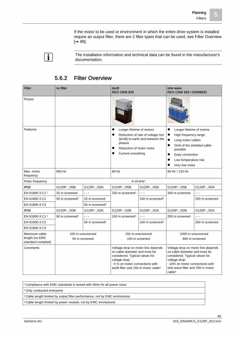
Planning 5Filters
89Siemens AG 016_SINAMICS_G120P_J5111en
If the motor to be used or environment in which the entire drive system is installedrequire an output filter, there are 2 filter types that can be used, see Filter Overview[ 89].
The installation information and technical data can be found in the manufacturer'sdocumentation.
5.6.2 Filter OverviewFilter no filter du/dt
REO CNW 833sine waveREO CNW 933 / CNW9332
Picture
Features l Longer lifetime of motorsl Reduction of rate of voltage rise
(dv/dt) to earth and between thephases
l Reduction of motor noisel Current smoothing
l Longer lifetime of motorsl High frequency rangel Long motor cablesl Omit of the shielded cable
possiblel Easy connectionl Low temperature risel Very low noise
Max. motorfrequency
650 Hz 60 Hz 60 Hz / 120 Hz
Pulse frequency 4-16 kHz1
IP55 G120P-../35B G120P-../35A G120P-../35B G120P-../35A G120P-../35B G120P-../35A
EN 61800-3 C1 2 25 m screened - - - 150 m screened3 - - - 200 m screened - - -
EN 61800-3 C2 50 m screened4 25 m screened 150 m screened3 200 m screened
EN 61800-3 C3 50 m screened4
IP20 G120P-../32B G120P-../32A G120P-../32B G120P-../32A G120P-../32B G120P-../32A
EN 61800-3 C1 2 50 m screened4 - - - 150 m screened3 - - - 200 m screened - - -
EN 61800-3 C2 50 m screened4 150 m screened3 200 m screened
EN 61800-3 C3
Maximum cablelength (no EMCstandard complied)
100 m unscreened50 m screened
150 m unscreened150 m screened
1000 m unscreened600 m screened
Comments Voltage drop on motor line dependson cable diameter and must beconsidered. Typical values forvoltage drop:- 5 % on motor connections withdu/dt filter and 150 m motor cable5
Voltage drop on motor line dependson cable diameter and must beconsidered. Typical values forvoltage drop:- 10% on motor connections withsine wave filter and 250 m motorcable5
1 Compliance with EMC standards is tested with 4kHz for all power sizes2 Only conducted emissions3 Cable length limited by output filter performance, not by EMC emmissions4 Cable length limited by power module, not by EMC emmissions
5 PlanningFuses
90Siemens AG 016_SINAMICS_G120P_J5111en
5 Voltage drop leads to higher currents if same power must be reached
5.7 Fuses
5.7.1 Where are fuses required?For fixed installations, a fuse is required for each cross-section reduction. The fusemust always safeguard the smallest cross-section in the electric circuit. Branchlines to fuses, sockets, and energy consumption meters may be dimensionedweaker provided that the line length does not exceed 2 m in control panels(switching panels, control cabinets) or 1 m in other locations. The branch linesmust be separated from combustible objects by an incombustible and thermalisolating intermediate layer.
5.7.2 Fuse typesThe following fuse types are used:l D system DIAZED screw-in fuse links (fusible links)l LV HRC (low-voltage high-rupturing-capacity fuse links) (up to 600 A) (fusible
links)l Miniature circuit breakers (MCB)l Electromagnetic releasesl Circuit breakers (to bypass a defective variable speed drive yet still safeguard
the motor against overloading)l Thermal overcurrent circuit breakers
DIAZED (diametral two-step Edison screw) screw-in fuse links (as well as fusecartridges or fusible links) are divided into 5 frame sizes.
Size Rated current Thread
D I 2 A, 4 A, 6 A, 10 A, 16 A E 16
D II 6 A, 10 A, 16 A, 20 A, 25 A E 27
D III 35 A, 50 A, 63 A E 33
D IV 80 A, 100 A R 1¼"
D V 125 A, 160 A, 200 A R 2"
Frame sizes D IV and D V are seldom used.
Low-voltage HRC fuse links are also known as blade-type fuses, blade fuses, andmain fuses. These are fusible links, yet they differ in form from screw-in fuse links.They have a larger volume than screw-in fuse links and a massive blade contact atboth ends, which allows them to carry and break larger currents.They are generally used to connect a house to a power supply system, or inelectrical power distribution systems for switchgear assemblies according toEN 60439LV HRC fuses can be used as individual fuses, in which case a fuse handle mustbe inserted/pulled. 3 fuses can also be mounted in a single box, however, in whichcase the cover then serves as a fuse holder and all fuses are inserted or removedat the same time (LV HRC fuse isolators).
D system DIAZEDscrew-in fuse links
Low-voltage high-rupturing-capacity (LVHRC) fuse links
Planning 5Fuses
91Siemens AG 016_SINAMICS_G120P_J5111en
WARNING
Arc generationRemoving this type of fuse when under load poses a high risk of an arc beingproduced. This causes a high current to flow along with high temperatures. Therisk is reduced by using fuse isolators. LV HRC fuses must only be replaced by specialists with the appropriate tools
and necessary protective equipment. The protective equipment is not necessarily essential if it is certain that there
is no load on the relevant electric circuit, as hazardous arcs only arise whenunder load.
The miniature circuit breaker (automatic circuit breaker) offers the followingadvantages over a fuse:l Constant readiness for operation, meaning it is immediately ready to use again
after tripping if there is no more overloadl Low space requirementsl The tripping characteristic does not change due to agingl The line can be utilized better as starting currents do not result in trips when
the switch is selected correctlyl They can be used as switches if specially marked as such with a symbol. In
special cases where the electric circuit is only switched occasionally, it is alsopermitted to have switches that do not bear this symbol
Motor starter protectors are used both as protective devices and switching devicesfor motors. The standard MSP is a three-pole, manually operated switch withthermal overcurrent release. In modern devices, electromagnetic releases are alsoinstalled. Auxiliary contacts are often switched, too. Motor starter protectors arebuilt in various sizes with a rated current of up to approximately 200 A. Thereleases are available in different versions:l Quick-response releases for if the starting current does not rise too high and
last for too long, which is generally the case for no-load starting and motorswith low speeds
l Slow releases for when the motor is intended to start-up under load (heavystarting) or for motors with high speeds
5.7.3 Overcurrent protectionThe electrical cables must be protected against overcurrent to avoid both electricaland fire hazards as a result of cables overheating. This means that all electriccircuits in an installation must be fused against short-circuits and overloads inaccordance with national and international regulations.When taking the measurements, we recommend selecting the next largeststandard value above the G120P's respective maximum input current.
The G120P must be protected against short-circuits to prevent electrical hazards orelectrical fire hazards. The short-circuit protection must always be in place at thestart of the supply. The size of the fuse/miniature circuit breaker is dependent onthe maximum input current.When taking the measurements, we recommend selecting the next largeststandard value above the G120P's respective maximum input current.The fuses must be suitable for use in an electric circuit that can supply asymmetrical current of up to 100,000 A (eff) at a maximum voltage of 480 VAC.
Miniature circuit breakers(MCBs)
Motor starter protectors(MSPs)
Overcurrent protection
Short-circuit protection

5 PlanningFuses
92Siemens AG 016_SINAMICS_G120P_J5111en
The G120P guarantees full short-circuit protection in the event of a short-circuit atthe motor output.
The G120P has internal overload protection which complies with UL508C. I2t isactive for each factory setting. Motor overload protection can also be achieved byusing an external motor PTC.Max. input and output current:
Power(kW)
Frame size Max. input current(LO)
Max. outputcurrent (LO)
RecommendedSiemens fuse
0.37 A 1.3 A 1.3 A 3NE1813-0
0.55 A 1.8 A 1.7 A 3NE1813-0
0.75 A 2.3 A 2.2 A 3NE1813-0
1.1 A 3.2 A 3.1 A 3NE1813-0
1.5 A 4.2 A 4.1 A 3NE1813-0
2.2 A 6.1 A 5.9 A 3NE1813-0
3 A 8.0 A 7.7 A 3NE1813-0
4 B 10.5 A 10.2 A 3NE1813-0
5.5 B 13.6 A 13.2 A 3NE1814-0
7.5 B 18.6 A 18.0 A 3NE1815-0
11 C 26.9 A 26.0 A 3NE1803-0
15 C 33.1 A 32.0 A 3NE1817-0
18.5 C 39.2 A 38.0 A 3NE1817-0
22 D 42 A 45 A 3NE1818-0
30 D 56 A 60 A 3NE1820-0
37 E 70 A 75 A 3NE1021-0
45 E 84 A 90 A 3NE1022-0
55 F 102 A 110 A 3NE1224-0
75 F 135 A 145 A 3NE1225-0
90 F 166 A 178 A 3NE1227-0
5.7.4 Operation with a residual current protective device (RCD)Wherever possible, avoid using RCDs for variable speed drives with EMC filters, asthe leakage currents in these devices are higher than in unfiltered devices.If you require an RCD, use a variable speed drive without EMC filters.In exceptional circumstances, a variable speed drive with filter A can be used.If you require an RCD for fire protection, for example, this must meet the followingconditions. For further information on RCD switches, read the Siemens "Residualcurrent protective devices" guide (order number: E10003-E38-10T-G3011).
In the event of a variable speed drive fault, smooth residual currents or residualcurrents with slight residual ripple can occur. Pulsating-current-sensitive residualcurrent protective devices cannot detect and disconnect such fault currents. Theyare also negatively affected in terms of their tripping function. This is why electricalloads that generate such fault currents in the event of faults must not be operatedwith pulsating-current-sensitive RCDs on the electrical supply network.
Overload protection
Do not use an RCD
Requirements for RCDswitches

Planning 5Service switch
93Siemens AG 016_SINAMICS_G120P_J5111en
As a result, only universal-current-sensitive RCDs (type B) may be used inconjunction with variable speed drives. These are suitable for use in three-phasecurrent systems with 50/60 Hz.
Universal-current-sensitive RCDs (type B) are marked with the symbol.
When planning and installing electrical installations, it must be noted that electricalconsumers, such as variable speed drives, that generate smooth DC fault currentsin the event of a fault are assigned their own circuit with a universal-current-sensitive RCD (type B).It is not permitted to branch electric circuits with these types of electricalconsumers to pulsating-current-sensitive RCDs (type B). Consumers that may bethe source of smooth DC fault currents in the event of a fault would affect thetripping ability of the pulsating-current-sensitive RCDs (type A).
When using residual current operated circuit breakers, the G120P functions withoutunwanted disconnections under the following preconditions:l A G120P with EMC filter A is usedl A type B residual current operated circuit breaker is usedl The trip limit of the residual current operated circuit breaker is 300 mAl The neutral conductor of the network is groundedl Each G120P is supplied by its own residual current operated circuit breakerl The output cables are shorter than 50 m (shielded) or 100 m (unshielded)
NOTICE
Residual current operated circuit breakers in useResidual current operated circuit breakers in use must offer protection againstdirect-current components in the fault current and be suitable for temporarilydischarging peaks in pulse current. Fuse the variable speed drive separately Observe the respective country requirements and those of the regional energy
supplier
5.8 Service switchIn most countries, the standards and safety regulations prescribe a service switchfor service purposes in the motor's supply line, which must be installed betweenthe variable speed drive and the motor.You can safeguard the variable speed drive against operation faults using aservice switch with an additional NO contact. For more information, seerecommended settings 2 on the next page.Breaking a cable at the variable speed drive output when under voltage leads to anovervoltage fault in the variable speed drive due to the induction being reversed. Inextreme cases, it can also result in irreparable damage to the variable speeddrive's power circuit, particularly if a contactor is used instead of a mechanicalswitching device.To perform maintenance, the service technician or customer must first switch offthe entire application (including the variable speed drive) before opening a serviceswitch. There are various ways of preventing the power circuit from becomingirreparably damaged or fault messages from arising due to operation faults.
Operation with residualcurrent operated circuitbreakers

5 PlanningService switch
94Siemens AG 016_SINAMICS_G120P_J5111en
NOTICE
Close the service switch or contactor during operationClosing a switch installed between a variable speed drive and a motor while thevariable speed drive is in operation results in the motor's current consumptionmultiplying by six. If this should occur, the variable speed drive switches off due toovercurrent. Only close the service switch/contactor when the variable speed drive is not in
operation.
MPR = Motor protection relaysSS = Service switchesF = Fuses
Various types of service switches are available, in terms of their design andnumber of contacts. The most common types, with a large red knob, have 3 NOcontacts for the motor supply. However, there are also other service switchesavailable with additional NO contacts or NC contacts, for example the Siemens3LD2.
It is crucial to connect the motor cable shield correctly in the service switch.The shield must be drawn through to the motor from the G120P output withoutinterruptions to prevent any EMC problems from occurring.
If using a normal service switch without additional NO or NC contacts, you cannotsafeguard the variable speed drive against operation faults directly at the serviceswitch. Attach a warning sign to the switch in order to avoid operation faults.
Types of serviceswitches
Connection in the serviceswitch
Recommended settings1

Planning 5Service switch
95Siemens AG 016_SINAMICS_G120P_J5111en
Use a service switch with an additional NO contact for direct variable speed driveprotection against operation faults at the service switch. This requires the switch-oncommand to be fed via the additional NO contact.If the motor supply contactor is opened, the variable speed drive's power circuit isisolated from its output terminals.To isolate the G120P power circuit from the variable speed drive's output terminals,you can use the "Enable operation" digital command. This prevents the reverseinduction that results from operating the service switch from affecting the G120Ppower circuit.
When using the "Enable operation" setting:l The reverse induction that results from operating the service switch has no
effect on the G120P power circuit.
Parameter settings (Enable operation at DI0)
Parameters Description
p0840[0] = r722.0 Switch-on command at DI0
p0852[0] = r722.0 Enable operation with DI0
l Contact closed -> RUN command can be activatedl Contact open -> the motor runs down to a standstill
Technically speaking, you can install the service switch at the input for the variablespeed drive. An additional NO contact is not required for the switch-on command.
WARNING
Dangerous voltage in DC linkThe DC link carries dangerous voltages during the electrical discharge period,which can take up to 5 minutes after isolating the variable speed drive from thenetwork. Wait until the DC link has fully discharged before making adjustments to the
system.
An emergency stop button on the variable speed drive's motor cable orconnecting cable must not be used as an "emergency stop mechanism" (see EN60204, 9.2.5.4). Consult your national standards and safety regulations, as theseusually prescribe a lockable service switch.
Recommended settings2
Service switch at input ofvariable speed drive

5 PlanningOutput contactors and motor protection relays
96Siemens AG 016_SINAMICS_G120P_J5111en
5.9 Output contactors and motor protection relays
Motor contactors are installed on the output side for many variable speed driveapplications.If one of these contactors interrupts the line between the variable speed drive andthe motor during operation, an alarm appears on the G120P's display to warn ofno-load at the variable speed drive. If this happens, the variable speed drivecontinues to run, meaning it still carries voltage at the output. This state does notpose any danger for the variable speed drive.
NOTICE
Close the contactor during operationClosing a switch installed between a variable speed drive and a motor while thevariable speed drive is in operation results in the motor's current consumptionmultiplying by six. If this should occur, the variable speed drive switches off due toovercurrent. Only close the service switch/contactor when the variable speed drive is not in
operation If possible, avoid the use of motor contactors
It only makes sense to use motor contactors for a bypass application. In this case,you must check the controls to ensure that the contactor is not switched on until thevariable speed drive is at a standstill (in standby).You should also ensure that the motor contactor and the variable speed drive'srelease are not switched on together to prevent the error referred to above fromarising.
5.10 Operation on non-grounded networksIt is only possible to operate on non-grounded power supply networks usingG120Ps with degree of protection IP20/NEMA 0 and no EMC filters.Devices with integrated EMC line filters cannot be operated on non-groundednetworks.G120Ps with degree of protection IP55/NEMA 12 cannot be operated on non-grounded power supply networks.IT systems are also classed as non-grounded networks in this context. For moreinformation, also refer to the following section Current distribution systems [ 97]The G120P with degree of protection IP20 functions on non-grounded networksand continues to operate when an input phase is connected to ground. If an outputphase has a ground fault, the G120P switches off and displays a correspondingmessage.
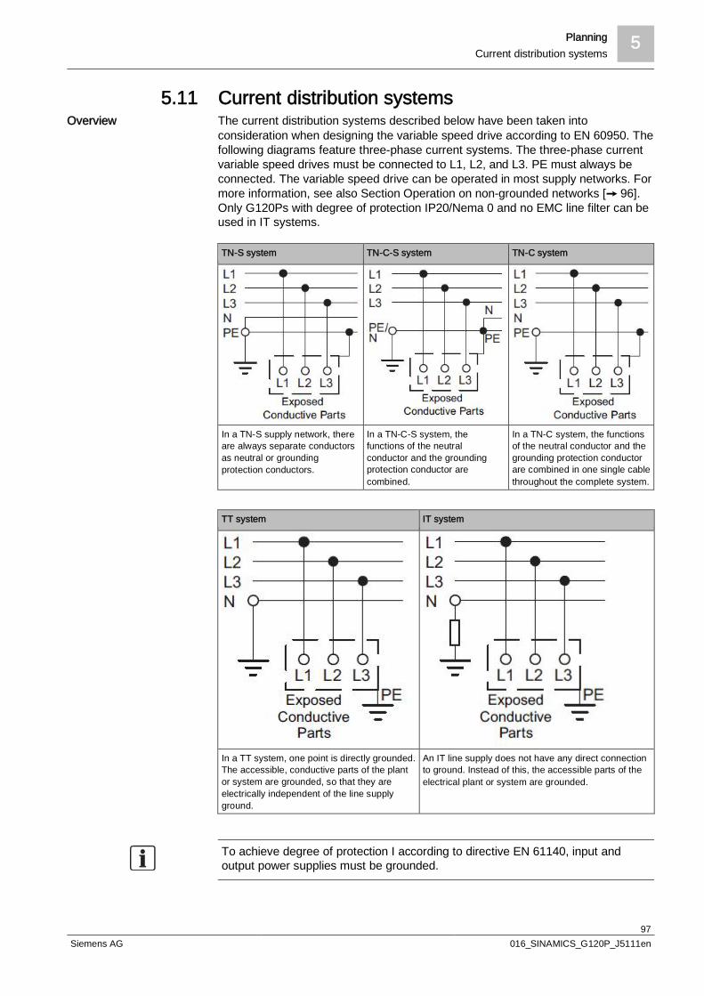
Planning 5Current distribution systems
97Siemens AG 016_SINAMICS_G120P_J5111en
5.11 Current distribution systemsThe current distribution systems described below have been taken intoconsideration when designing the variable speed drive according to EN 60950. Thefollowing diagrams feature three-phase current systems. The three-phase currentvariable speed drives must be connected to L1, L2, and L3. PE must always beconnected. The variable speed drive can be operated in most supply networks. Formore information, see also Section Operation on non-grounded networks [ 96].Only G120Ps with degree of protection IP20/Nema 0 and no EMC line filter can beused in IT systems.
TN-S system TN-C-S system TN-C system
In a TN-S supply network, thereare always separate conductorsas neutral or groundingprotection conductors.
In a TN-C-S system, thefunctions of the neutralconductor and the groundingprotection conductor arecombined.
In a TN-C system, the functionsof the neutral conductor and thegrounding protection conductorare combined in one single cablethroughout the complete system.
TT system IT system
In a TT system, one point is directly grounded.The accessible, conductive parts of the plantor system are grounded, so that they areelectrically independent of the line supplyground.
An IT line supply does not have any direct connectionto ground. Instead of this, the accessible parts of theelectrical plant or system are grounded.
To achieve degree of protection I according to directive EN 61140, input andoutput power supplies must be grounded.
Overview

6 FunctionsOverview of the functions
98Siemens AG 016_SINAMICS_G120P_J5111en
6 Functions
6.1 Overview of the functionsBefore you set the variable speed drive functions, you should complete thefollowing commissioning steps:l Basic commissioningl If required: adjust the terminal stripl If required: configure the fieldbus
Functions relevant to all applications Functions required in special applications only
The functions that you require in each applicationare shown in a dark color in the function overviewabove.In the quick commissioning, the parameters ofthese functions are assigned an appropriate basicsetting, so that in many cases the motor can beoperated without having to assign any otherparameters.
The functions whose parameters you only need toadapt when actually required are shown in whitein the function overview above.
Variable speed drive control isresponsible for all of the othervariable speed drive functions.Among other things, it defines howthe variable speed drive responds toexternal control signals.
The protection functions avoidoverloads and operating states thatcould cause damage to the motor,variable speed drive, and drivenload. The motor temperaturemonitoring, for example, is set here.
The command source defines wherethe control signals are received fromto switch on the motor, e.g. viadigital inputs or a fieldbus.
The status messages provide digitaland analog signals at the ControlUnit outputs or via the fieldbus.Examples include the current speedof the motor or fault message issuedby the variable speed drive.
The setpoint source defines how thespeed setpoint for the motor isspecified, e.g. via an analog input ora fieldbus.
The functions matching theapplication allow you to control amotor holding brake or implement ahigher-level pressure or temperature
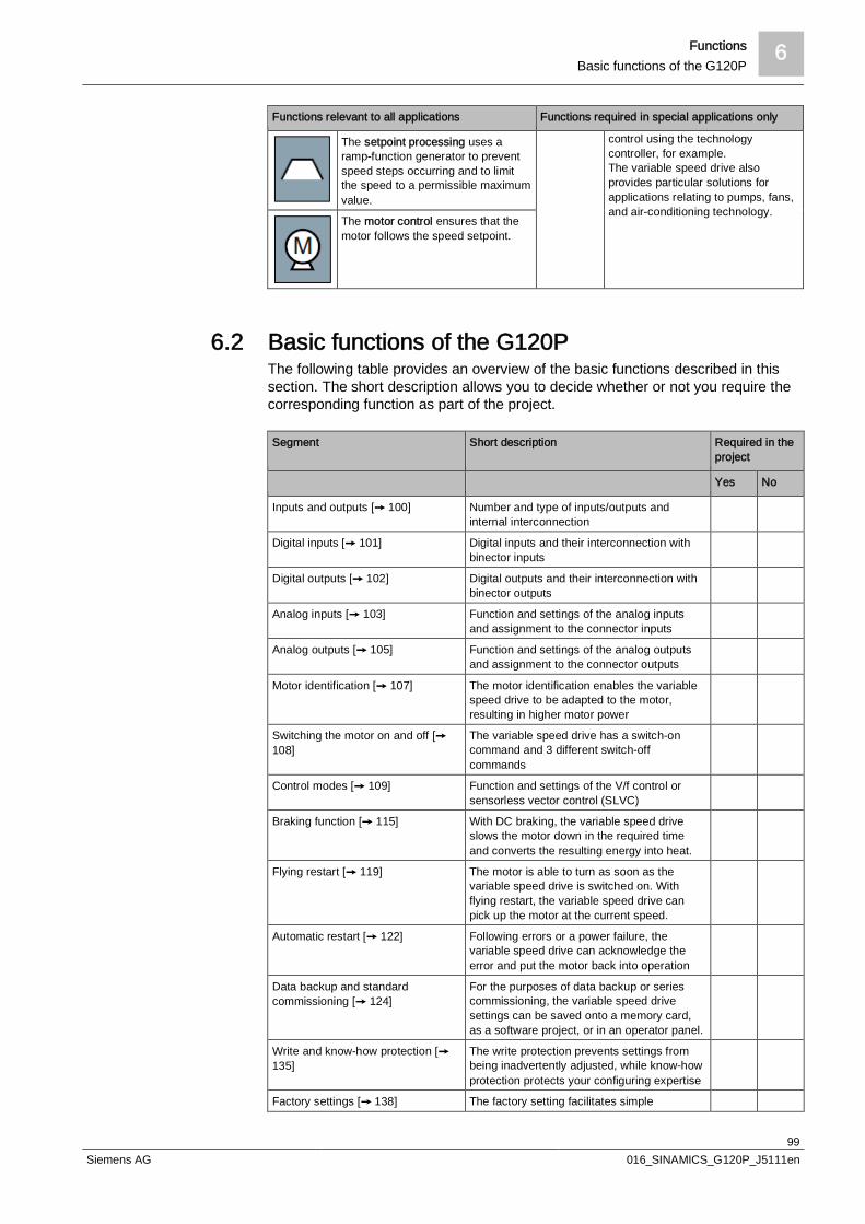
Functions 6Basic functions of the G120P
99Siemens AG 016_SINAMICS_G120P_J5111en
Functions relevant to all applications Functions required in special applications only
The setpoint processing uses aramp-function generator to preventspeed steps occurring and to limitthe speed to a permissible maximumvalue.
control using the technologycontroller, for example.The variable speed drive alsoprovides particular solutions forapplications relating to pumps, fans,and air-conditioning technology.
The motor control ensures that themotor follows the speed setpoint.
6.2 Basic functions of the G120PThe following table provides an overview of the basic functions described in thissection. The short description allows you to decide whether or not you require thecorresponding function as part of the project.
Segment Short description Required in theproject
Yes No
Inputs and outputs [ 100] Number and type of inputs/outputs andinternal interconnection
Digital inputs [ 101] Digital inputs and their interconnection withbinector inputs
Digital outputs [ 102] Digital outputs and their interconnection withbinector outputs
Analog inputs [ 103] Function and settings of the analog inputsand assignment to the connector inputs
Analog outputs [ 105] Function and settings of the analog outputsand assignment to the connector outputs
Motor identification [ 107] The motor identification enables the variablespeed drive to be adapted to the motor,resulting in higher motor power
Switching the motor on and off [108]
The variable speed drive has a switch-oncommand and 3 different switch-offcommands
Control modes [ 109] Function and settings of the V/f control orsensorless vector control (SLVC)
Braking function [ 115] With DC braking, the variable speed driveslows the motor down in the required timeand converts the resulting energy into heat.
Flying restart [ 119] The motor is able to turn as soon as thevariable speed drive is switched on. Withflying restart, the variable speed drive canpick up the motor at the current speed.
Automatic restart [ 122] Following errors or a power failure, thevariable speed drive can acknowledge theerror and put the motor back into operation
Data backup and standardcommissioning [ 124]
For the purposes of data backup or seriescommissioning, the variable speed drivesettings can be saved onto a memory card,as a software project, or in an operator panel.
Write and know-how protection [135]
The write protection prevents settings frombeing inadvertently adjusted, while know-howprotection protects your configuring expertise
Factory settings [ 138] The factory setting facilitates simple

6 FunctionsBasic functions of the G120P
100Siemens AG 016_SINAMICS_G120P_J5111en
Segment Short description Required in theproject
Yes No
applications or serves as a starting point forconfiguring complex applications
6.2.1 Inputs and outputsThe variable speed drive has the following digital and analog inputs and outputs:l 6 isolated digital inputs with a separate potential group to prevent potential
transfersl 3 digital outputsl 4 isolated analog inputs for EMC-compliant installation without the need for
additional componentsl 2 analog outputs
The terminal assignment at the CU's terminal strips can be found in SectionTerminal strips in the Control Unit [ 41].:Permissible wire cross-sections for the terminal connections are: 0.5 to 2.5 mm²
The terminals are connected internally as follows:
Before you adapt the inputs and outputs of the variable speed drive, you shouldhave completed the basic commissioning.In the basic commissioning, select an assignment of the variable speed driveinterfaces from several predefined configurations. This is done using the MacParP0015 macro parameter. Section contains the latest HVAC applications and thecorresponding macro numbers.If none of the predefined configurations completely matches your application, thenyou must adapt the assignment of the individual inputs and outputs. You do this bychanging the internal interconnection of an input or output using BICO technology.
Available inputs andoutputs
Terminal assignment
Internal interconnection
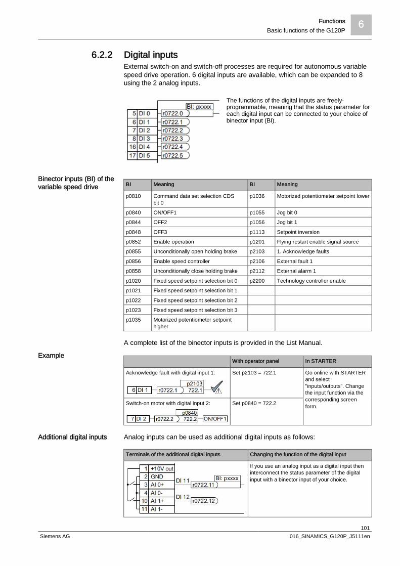
Functions 6Basic functions of the G120P
101Siemens AG 016_SINAMICS_G120P_J5111en
6.2.2 Digital inputsExternal switch-on and switch-off processes are required for autonomous variablespeed drive operation. 6 digital inputs are available, which can be expanded to 8using the 2 analog inputs.
The functions of the digital inputs are freely-programmable, meaning that the status parameter foreach digital input can be connected to your choice ofbinector input (BI).
BI Meaning BI Meaning
p0810 Command data set selection CDSbit 0
p1036 Motorized potentiometer setpoint lower
p0840 ON/OFF1 p1055 Jog bit 0
p0844 OFF2 p1056 Jog bit 1
p0848 OFF3 p1113 Setpoint inversion
p0852 Enable operation p1201 Flying restart enable signal source
p0855 Unconditionally open holding brake p2103 1. Acknowledge faults
p0856 Enable speed controller p2106 External fault 1
p0858 Unconditionally close holding brake p2112 External alarm 1
p1020 Fixed speed setpoint selection bit 0 p2200 Technology controller enable
p1021 Fixed speed setpoint selection bit 1
p1022 Fixed speed setpoint selection bit 2
p1023 Fixed speed setpoint selection bit 3
p1035 Motorized potentiometer setpointhigher
A complete list of the binector inputs is provided in the List Manual.
With operator panel In STARTER
Acknowledge fault with digital input 1: Set p2103 = 722.1 Go online with STARTERand select"inputs/outputs". Changethe input function via thecorresponding screenform.Switch-on motor with digital input 2: Set p0840 = 722.2
Analog inputs can be used as additional digital inputs as follows:
Terminals of the additional digital inputs Changing the function of the digital input
If you use an analog input as a digital input theninterconnect the status parameter of the digitalinput with a binector input of your choice.
Binector inputs (BI) of thevariable speed drive
Example
Additional digital inputs
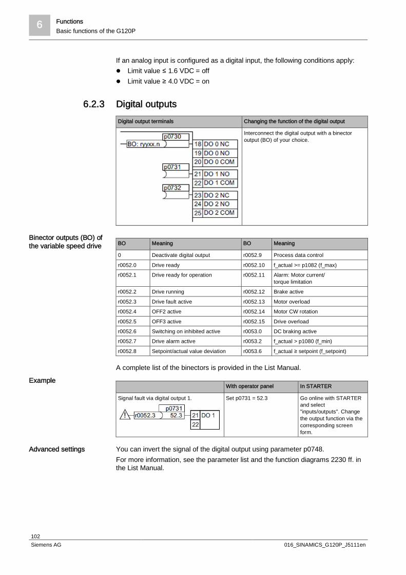
6 FunctionsBasic functions of the G120P
102Siemens AG 016_SINAMICS_G120P_J5111en
If an analog input is configured as a digital input, the following conditions apply:l Limit value ≤ 1.6 VDC = offl Limit value ≥ 4.0 VDC = on
6.2.3 Digital outputsDigital output terminals Changing the function of the digital output
Interconnect the digital output with a binectoroutput (BO) of your choice.
BO Meaning BO Meaning
0 Deactivate digital output r0052.9 Process data control
r0052.0 Drive ready r0052.10 f_actual >= p1082 (f_max)
r0052.1 Drive ready for operation r0052.11 Alarm: Motor current/torque limitation
r0052.2 Drive running r0052.12 Brake active
r0052.3 Drive fault active r0052.13 Motor overload
r0052.4 OFF2 active r0052.14 Motor CW rotation
r0052.5 OFF3 active r0052.15 Drive overload
r0052.6 Switching on inhibited active r0053.0 DC braking active
r0052.7 Drive alarm active r0053.2 f_actual > p1080 (f_min)
r0052.8 Setpoint/actual value deviation r0053.6 f_actual ≥ setpoint (f_setpoint)
A complete list of the binectors is provided in the List Manual.
With operator panel In STARTER
Signal fault via digital output 1. Set p0731 = 52.3 Go online with STARTERand select"inputs/outputs". Changethe output function via thecorresponding screenform.
You can invert the signal of the digital output using parameter p0748.For more information, see the parameter list and the function diagrams 2230 ff. inthe List Manual.
Binector outputs (BO) ofthe variable speed drive
Example
Advanced settings
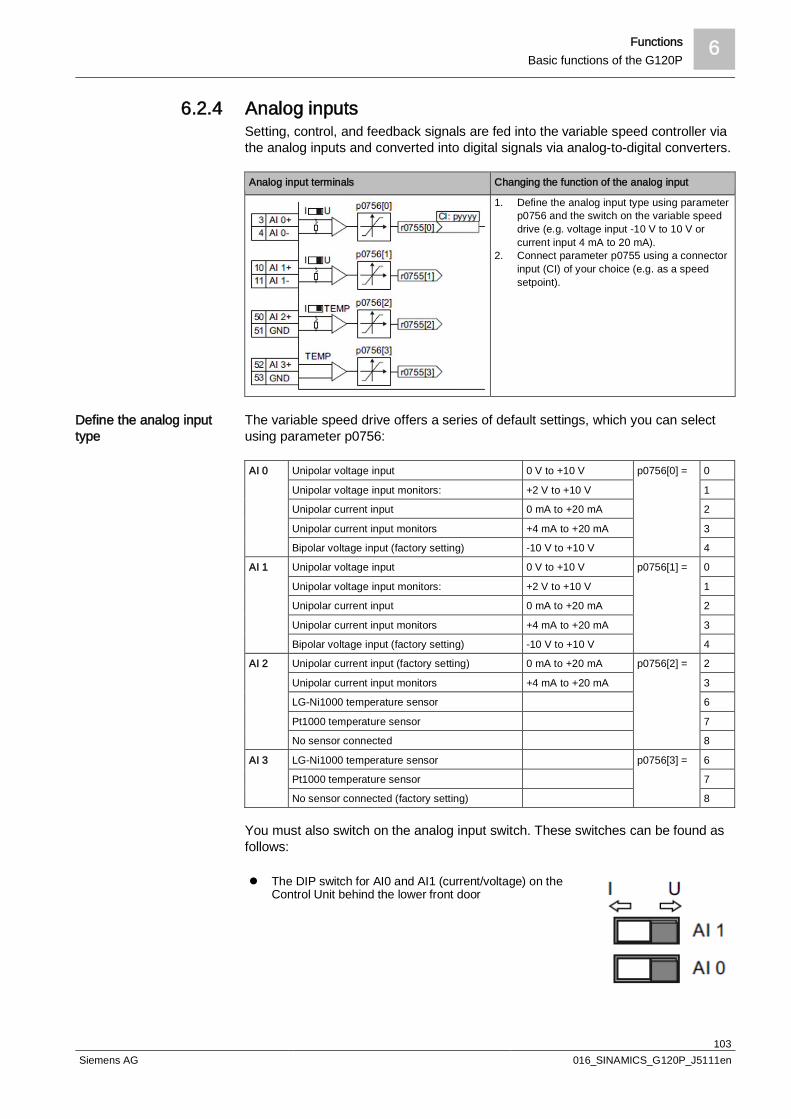
Functions 6Basic functions of the G120P
103Siemens AG 016_SINAMICS_G120P_J5111en
6.2.4 Analog inputsSetting, control, and feedback signals are fed into the variable speed controller viathe analog inputs and converted into digital signals via analog-to-digital converters.
Analog input terminals Changing the function of the analog input
1. Define the analog input type using parameterp0756 and the switch on the variable speeddrive (e.g. voltage input -10 V to 10 V orcurrent input 4 mA to 20 mA).
2. Connect parameter p0755 using a connectorinput (CI) of your choice (e.g. as a speedsetpoint).
The variable speed drive offers a series of default settings, which you can selectusing parameter p0756:
AI 0 Unipolar voltage input 0 V to +10 V p0756[0] = 0
Unipolar voltage input monitors: +2 V to +10 V 1
Unipolar current input 0 mA to +20 mA 2
Unipolar current input monitors +4 mA to +20 mA 3
Bipolar voltage input (factory setting) -10 V to +10 V 4
AI 1 Unipolar voltage input 0 V to +10 V p0756[1] = 0
Unipolar voltage input monitors: +2 V to +10 V 1
Unipolar current input 0 mA to +20 mA 2
Unipolar current input monitors +4 mA to +20 mA 3
Bipolar voltage input (factory setting) -10 V to +10 V 4
AI 2 Unipolar current input (factory setting) 0 mA to +20 mA p0756[2] = 2
Unipolar current input monitors +4 mA to +20 mA 3
LG-Ni1000 temperature sensor 6
Pt1000 temperature sensor 7
No sensor connected 8
AI 3 LG-Ni1000 temperature sensor p0756[3] = 6
Pt1000 temperature sensor 7
No sensor connected (factory setting) 8
You must also switch on the analog input switch. These switches can be found asfollows:
l The DIP switch for AI0 and AI1 (current/voltage) on theControl Unit behind the lower front door
Define the analog inputtype
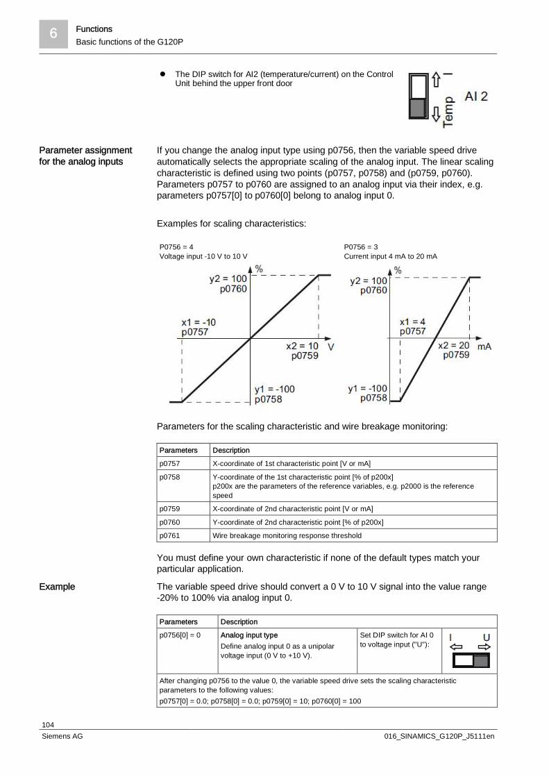
6 FunctionsBasic functions of the G120P
104Siemens AG 016_SINAMICS_G120P_J5111en
l The DIP switch for AI2 (temperature/current) on the ControlUnit behind the upper front door
If you change the analog input type using p0756, then the variable speed driveautomatically selects the appropriate scaling of the analog input. The linear scalingcharacteristic is defined using two points (p0757, p0758) and (p0759, p0760).Parameters p0757 to p0760 are assigned to an analog input via their index, e.g.parameters p0757[0] to p0760[0] belong to analog input 0.
Examples for scaling characteristics:
P0756 = 4Voltage input -10 V to 10 V
P0756 = 3Current input 4 mA to 20 mA
Parameters for the scaling characteristic and wire breakage monitoring:
Parameters Description
p0757 X-coordinate of 1st characteristic point [V or mA]
p0758 Y-coordinate of the 1st characteristic point [% of p200x]p200x are the parameters of the reference variables, e.g. p2000 is the referencespeed
p0759 X-coordinate of 2nd characteristic point [V or mA]
p0760 Y-coordinate of 2nd characteristic point [% of p200x]
p0761 Wire breakage monitoring response threshold
You must define your own characteristic if none of the default types match yourparticular application.
The variable speed drive should convert a 0 V to 10 V signal into the value range-20% to 100% via analog input 0.
Parameters Description
p0756[0] = 0 Analog input typeDefine analog input 0 as a unipolarvoltage input (0 V to +10 V).
Set DIP switch for AI 0to voltage input ("U"):
After changing p0756 to the value 0, the variable speed drive sets the scaling characteristicparameters to the following values:p0757[0] = 0.0; p0758[0] = 0.0; p0759[0] = 10; p0760[0] = 100
Parameter assignmentfor the analog inputs
Example

Functions 6Basic functions of the G120P
105Siemens AG 016_SINAMICS_G120P_J5111en
Adapt the characteristic:
p0757[0] = 0.0 Analog input characteristic (x1, y1)0 V corresponds to 20%
Voltage input, 0 V to 10 V
p0758[0] = 20.0
p0759[0] = 10.0 Analog input characteristic (x2, y2)10 V corresponds to 100%p0760[0] = 100.0
You define the analog input function by interconnecting a connector input of yourchoice with parameter p0755. Parameter p0755 is assigned to the particularanalog input via its index, e.g. parameter p0755[0] is assigned to analog input 0.Connector inputs (CI) of the variable speed drive (selection):
CI Meaning CI Meaning
p1070 Main setpoint p1522 Torque limit, upper
p1075 Supplementary setpoint p2253 Technology controller setpoint 1
p1503 Torque setpoint p2264 Technology controller actualvalue
p1511 Supplementary torque 1
A complete list of the connector inputs is provided in the List Manual.
With operator panel In STARTER
Analog input 0 is the source for theadditional setpoint.
Set p1075 = 755[0] Go online with STARTERand select"inputs/outputs". Changethe output function via thecorresponding screenform.
For more information, see the parameter list and the function diagrams 9566 ff. inthe List Manual.
6.2.5 Analog outputsThe purpose of the analog outputs is essentially to present status variables such asoutput frequency, motor voltage, or current motor current within a scalable area.
Analog output terminals Changing the function of the analog output
1. Define the analog output type using parameterp0776, e.g. voltage output -10 V to 10 V or currentoutput 4 mA to 20 mA).
2. Connect parameter p0771 using a connectoroutput of your choice, e.g. the current speed.Connector outputs are marked with "CO" in theparameter list of the List Manual.
The variable speed drive offers a series of default settings, which you can selectusing parameter p0776:
AO 0 Current output (factory setting) 0 mA to +20 mA p0776[0] = 0
Voltage output 0 V to 10 V 1
Current output +4 mA to +20 mA 2
Defining the analog inputfunction
Example
Define the analog outputtype

6 FunctionsBasic functions of the G120P
106Siemens AG 016_SINAMICS_G120P_J5111en
AO 1 Current output (factory setting) 0 mA to +20 mA p0776[1] = 0
Voltage output 0 V to +10 V 1
Current output +4 mA to +20 mA 2
If you change the analog output type, then the inverter automatically selects theappropriate scaling of the analog output. The linear scaling characteristic is definedusing two points (p0777, p0778) and (p0779, p0780).
P0776 = 1Voltage output 0 V to 10 V
P0776 = 2Current output 4 mA to 20 mA
Parameters p0777 to p0780 are assigned to an analog output via their index, e.g.parameters p0777[0] to p0770[0] belong to analog output 0.
Parameters Description
p0777 X-coordinate of the 1st characteristic point [% of p200x]p200x are the parameters of the reference variables, e.g. p2000 is the referencespeed.
p0778 Y coordinate of the 1st characteristic point [V or mA]
p0779 X coordinate of the 2nd characteristic point [% of p200x]
p0780 Y coordinate of the 2nd characteristic point [V or mA]
You must define your own characteristic if none of the default types match yourparticular application.
The variable speed drive should convert a signal in the value range 0% to 100%into a 6 mA to 12 mA output signal via analog output 0.
Parameters Description
p0776[0] = 2 Analog output typeDefine analog output 0 as current output.
After changing p0776 to the value 2, the variable speed drive sets thescaling characteristic parameters to the following values:p0777[0] = 0.0; p0778[0] = 4.0; p0779[0] = 100.0; p0780[0] = 20.0Adapt the characteristic:
p0777[0] = 0.0 Analog output characteristic (x1, y1)0.0% corresponds to 6 mA
Current output 6 mA to 12 mA
p0778[0] = -6.0
p0779[0] = 100.0 Analog output characteristic (x2, y2)100% corresponds to 12 mAp0780[0] = 12.0
Parameters for thescaling characteristic
Example
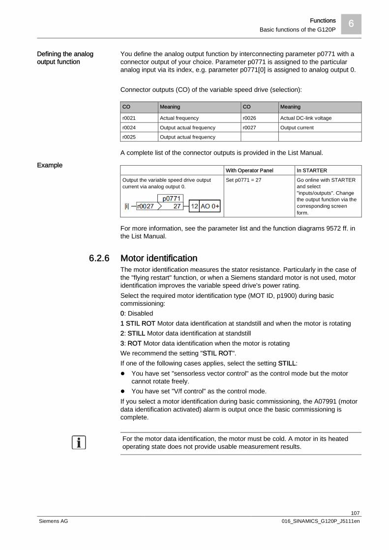
Functions 6Basic functions of the G120P
107Siemens AG 016_SINAMICS_G120P_J5111en
You define the analog output function by interconnecting parameter p0771 with aconnector output of your choice. Parameter p0771 is assigned to the particularanalog input via its index, e.g. parameter p0771[0] is assigned to analog output 0.
Connector outputs (CO) of the variable speed drive (selection):
CO Meaning CO Meaning
r0021 Actual frequency r0026 Actual DC-link voltage
r0024 Output actual frequency r0027 Output current
r0025 Output actual frequency
A complete list of the connector outputs is provided in the List Manual.
With Operator Panel In STARTER
Output the variable speed drive outputcurrent via analog output 0.
Set p0771 = 27 Go online with STARTERand select"inputs/outputs". Changethe output function via thecorresponding screenform.
For more information, see the parameter list and the function diagrams 9572 ff. inthe List Manual.
6.2.6 Motor identificationThe motor identification measures the stator resistance. Particularly in the case ofthe "flying restart" function, or when a Siemens standard motor is not used, motoridentification improves the variable speed drive's power rating.Select the required motor identification type (MOT ID, p1900) during basiccommissioning:0: Disabled1 STIL ROT Motor data identification at standstill and when the motor is rotating2: STILL Motor data identification at standstill3: ROT Motor data identification when the motor is rotatingWe recommend the setting "STIL ROT".If one of the following cases applies, select the setting STILL:l You have set "sensorless vector control" as the control mode but the motor
cannot rotate freely.l You have set "V/f control" as the control mode.If you select a motor identification during basic commissioning, the A07991 (motordata identification activated) alarm is output once the basic commissioning iscomplete.
For the motor data identification, the motor must be cold. A motor in its heatedoperating state does not provide usable measurement results.
Defining the analogoutput function
Example

6 FunctionsBasic functions of the G120P
108Siemens AG 016_SINAMICS_G120P_J5111en
CAUTION
Moving system components and loadsThe motor can move by up to a quarter of a revolution during motor dataidentification, meaning that connected system components and loads may alsomove as a result. This must not pose a safety hazard. Secure hazardous system components and loads before commencing the
motor data identification.
w Proceed as follows once basic commissioning is complete:
1. Switch the drive from AUTO to MANUAL
2. Switch on the drive
a The motor identification is performed
3. Reset the drive from MANUAL back to AUTO
a The drive is ready
The motor identification can be performed using BOP-2, IOP, or STARTERsoftware.You can perform the motor identification from scratch at any time by startingparameter p1900 and selecting the required setting.
6.2.7 Switching the motor on and offAfter switching on the supply voltage, the variable speed drive normally goes intothe "Ready to start" state. In this state, the variable speed drive waits for thecommand to switch on the motor:The variable speed drive switches on the motor with the ON command. Thevariable speed drive changes to the "Operation" state.
You can stop the motor in various ways: The 3 most important OFF commandsare:l OFF1
After the OFF1 command, the variable speed drive brakes the motor with theramp-down time of the ramp-function generator (p1120). The variable speeddrive switches off the motor once standstill has been reached. The variablespeed drive is ready to start again.ON and the subsequent OFF1 command can only be programmed together ata single source (for example, at the digital input).OFF1 can be combined with DC braking.
l OFF2The variable speed drive immediately switches off the motor without firstbraking it. The motor continues to run according to its moment of inertia.The OFF2 command can have a maximum of 2 sources, for example, a digitalinput. The OFF2 command is set by default at the BOP-2 stop button (double-click). This source is even still available when another source is programmedas OFF2, for example, another digital input.
l OFF3This command means "quick stop". After an OFF3 command, the variablespeed drive brakes the motor with the OFF3 ramp-down time. After reachingstandstill, the variable speed drive switches off the motor.The command is frequently used for exceptional operating situations where it is
Performing the motoridentification
Activating
Switching off
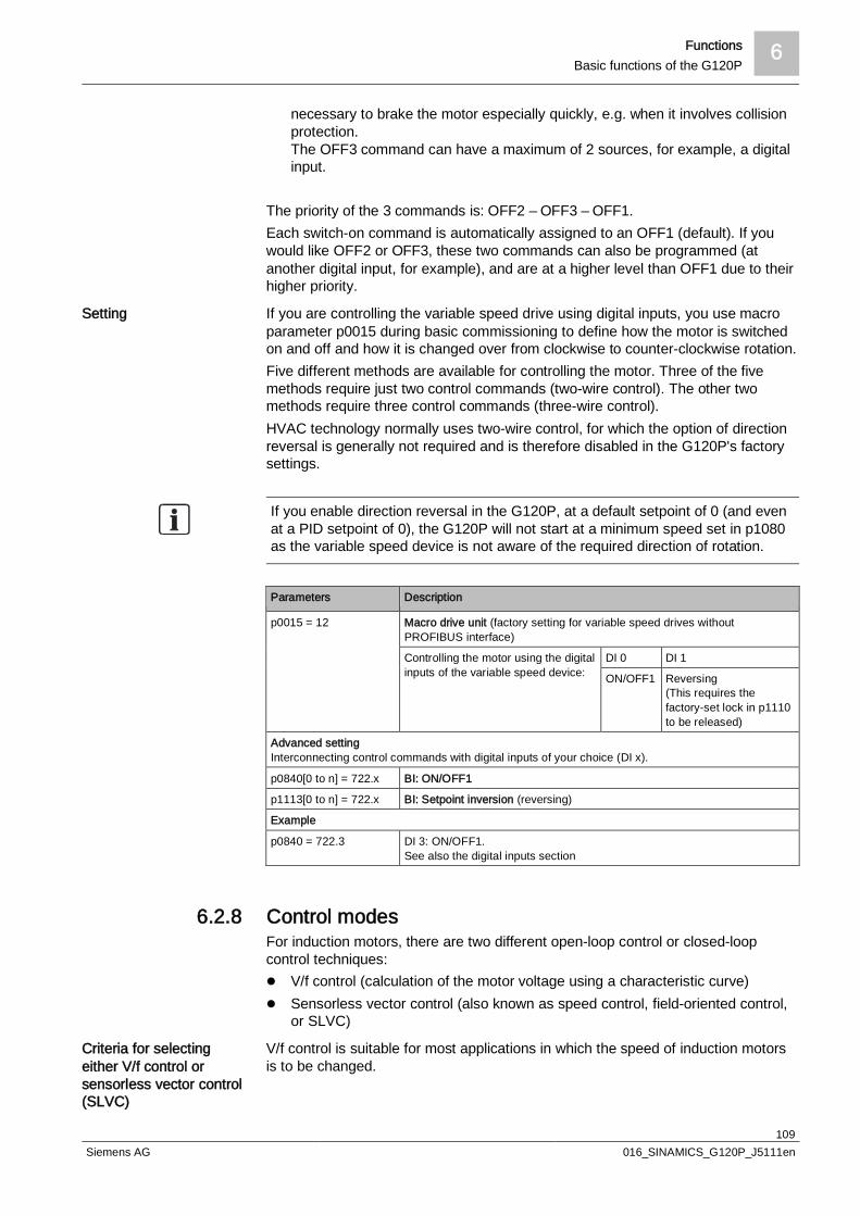
Functions 6Basic functions of the G120P
109Siemens AG 016_SINAMICS_G120P_J5111en
necessary to brake the motor especially quickly, e.g. when it involves collisionprotection.The OFF3 command can have a maximum of 2 sources, for example, a digitalinput.
The priority of the 3 commands is: OFF2 – OFF3 – OFF1.Each switch-on command is automatically assigned to an OFF1 (default). If youwould like OFF2 or OFF3, these two commands can also be programmed (atanother digital input, for example), and are at a higher level than OFF1 due to theirhigher priority.
If you are controlling the variable speed drive using digital inputs, you use macroparameter p0015 during basic commissioning to define how the motor is switchedon and off and how it is changed over from clockwise to counter-clockwise rotation.Five different methods are available for controlling the motor. Three of the fivemethods require just two control commands (two-wire control). The other twomethods require three control commands (three-wire control).HVAC technology normally uses two-wire control, for which the option of directionreversal is generally not required and is therefore disabled in the G120P's factorysettings.
If you enable direction reversal in the G120P, at a default setpoint of 0 (and evenat a PID setpoint of 0), the G120P will not start at a minimum speed set in p1080as the variable speed device is not aware of the required direction of rotation.
Parameters Description
p0015 = 12 Macro drive unit (factory setting for variable speed drives withoutPROFIBUS interface)
Controlling the motor using the digitalinputs of the variable speed device:
DI 0 DI 1
ON/OFF1 Reversing(This requires thefactory-set lock in p1110to be released)
Advanced settingInterconnecting control commands with digital inputs of your choice (DI x).
p0840[0 to n] = 722.x BI: ON/OFF1
p1113[0 to n] = 722.x BI: Setpoint inversion (reversing)
Example
p0840 = 722.3 DI 3: ON/OFF1.See also the digital inputs section
6.2.8 Control modesFor induction motors, there are two different open-loop control or closed-loopcontrol techniques:l V/f control (calculation of the motor voltage using a characteristic curve)l Sensorless vector control (also known as speed control, field-oriented control,
or SLVC)
V/f control is suitable for most applications in which the speed of induction motorsis to be changed.
Setting
Criteria for selectingeither V/f control orsensorless vector control(SLVC)

6 FunctionsBasic functions of the G120P
110Siemens AG 016_SINAMICS_G120P_J5111en
When compared to V/f control, sensorless vector control offers the followingadvantages:l The speed is more stable for motor load changesl Shorter ramp times when the setpoint changesl Larger tolerances for temporary line-side voltage drops or "brown-outs"l Acceleration and braking are possible with an adjustable maximum torquel Improved protection of the motor and the driven machine as a result of
improvements to the adjustable torque limitingl The full torque is possible at standstill.
The torque control is no longer applicable in FW version 4.6, although the torquemonitoring remains unaffected.
It is not permissible to use sensorless vector control in the following cases:l If the motor is too small compared to the variable speed drive. The motor's
rated power must not be less than a quarter of the variable speed drive's ratedpower
l If several motors are connected to one variable speed drivel If a power contactor is used between the variable speed drive and the motor,
and is opened when the motor is powered upl When the maximum motor speed exceeds the following values:
Variable speed drive pulse frequency 4 kHz and higher
Pole number of the motor 2-pole 4-pole 6-pole
Maximum motor speed [rpm] 14400 7200 4800
You are able to define a minimum and maximum speed:l Minimum speed p1080 – factory setting 0 [rpm]
The minimum speed is the lowest speed of the motor independent of the speedsetpoint. A minimum speed > 0 makes sense in applications, where the motorshould be operated with a speed = 0 after it has been switched on. Examplesinclude fans or pumps. For adequate cooling of self-cooling motors, werecommend a minimum speed of at least 20%.
l Maximum speed p1082 – factory setting 1,500 [rpm]The variable speed drive limits the motor speed to this value. The value isautomatically set to the motor's synchronous speed during basiccommissioning.
The ramp-up and ramp-down times define the maximum motor acceleration whenthe speed setpoint changes. The ramp-up and ramp-down time is the time betweenmotor standstill and the maximum speed, or between the maximum speed andmotor standstill.l Ramp-up time – factory setting 10 sl Ramp-down time – factory setting 30 s
Recommended ramp times
0.37 – 3 kW 30 s
4 – 15 kW 60 s
18.5 – 30 kW 90 s
37 – 90 kW 120 s
Defining the minimumand maximum speed
Ramp-up time and ramp-down time
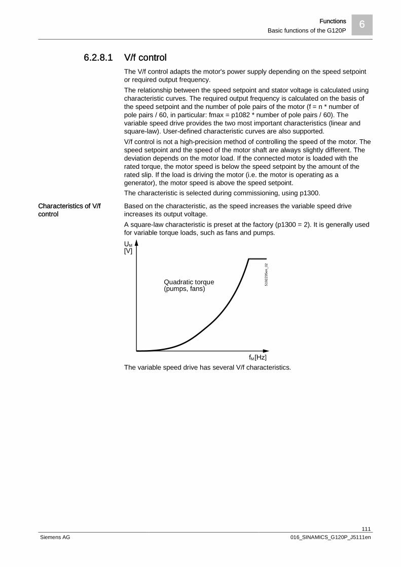
Functions 6Basic functions of the G120P
111Siemens AG 016_SINAMICS_G120P_J5111en
6.2.8.1 V/f controlThe V/f control adapts the motor's power supply depending on the speed setpointor required output frequency.The relationship between the speed setpoint and stator voltage is calculated usingcharacteristic curves. The required output frequency is calculated on the basis ofthe speed setpoint and the number of pole pairs of the motor (f = n * number ofpole pairs / 60, in particular: fmax = p1082 * number of pole pairs / 60). Thevariable speed drive provides the two most important characteristics (linear andsquare-law). User-defined characteristic curves are also supported.V/f control is not a high-precision method of controlling the speed of the motor. Thespeed setpoint and the speed of the motor shaft are always slightly different. Thedeviation depends on the motor load. If the connected motor is loaded with therated torque, the motor speed is below the speed setpoint by the amount of therated slip. If the load is driving the motor (i.e. the motor is operating as agenerator), the motor speed is above the speed setpoint.The characteristic is selected during commissioning, using p1300.
Based on the characteristic, as the speed increases the variable speed driveincreases its output voltage.A square-law characteristic is preset at the factory (p1300 = 2). It is generally usedfor variable torque loads, such as fans and pumps.
Quadratic torque(pumps, fans)
5192
Z05e
n_02
The variable speed drive has several V/f characteristics.
Characteristics of V/fcontrol
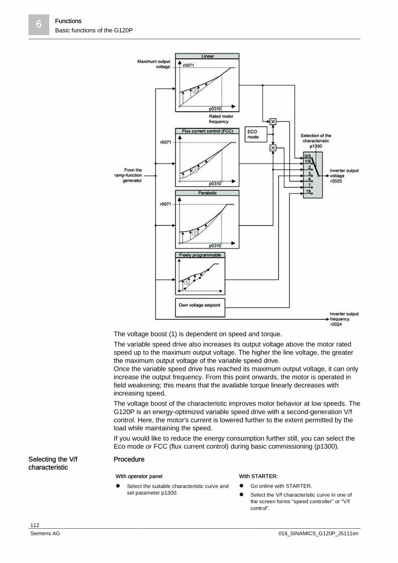
6 FunctionsBasic functions of the G120P
112Siemens AG 016_SINAMICS_G120P_J5111en
The voltage boost (1) is dependent on speed and torque.The variable speed drive also increases its output voltage above the motor ratedspeed up to the maximum output voltage. The higher the line voltage, the greaterthe maximum output voltage of the variable speed drive.Once the variable speed drive has reached its maximum output voltage, it can onlyincrease the output frequency. From this point onwards, the motor is operated infield weakening; this means that the available torque linearly decreases withincreasing speed.The voltage boost of the characteristic improves motor behavior at low speeds. TheG120P is an energy-optimized variable speed drive with a second-generation V/fcontrol. Here, the motor's current is lowered further to the extent permitted by theload while maintaining the speed.If you would like to reduce the energy consumption further still, you can select theEco mode or FCC (flux current control) during basic commissioning (p1300).
Procedure
With operator panel With STARTER:
l Select the suitable characteristic curve andset parameter p1300.
l Go online with STARTER.l Select the V/f characteristic curve in one of
the screen forms "speed controller" or "V/fcontrol".
Selecting the V/fcharacteristic
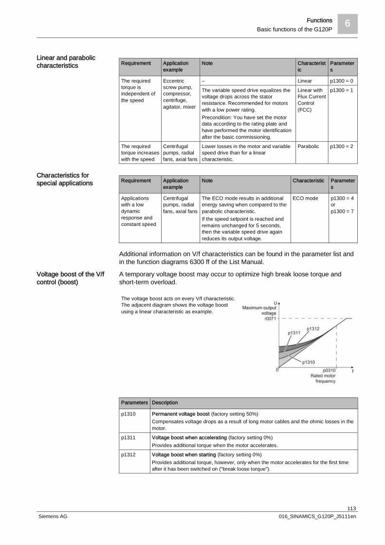
Functions 6Basic functions of the G120P
113Siemens AG 016_SINAMICS_G120P_J5111en
Requirement Applicationexample
Note Characteristic
Parameters
The requiredtorque isindependent ofthe speed
Eccentricscrew pump,compressor,centrifuge,agitator, mixer
– Linear p1300 = 0
The variable speed drive equalizes thevoltage drops across the statorresistance. Recommended for motorswith a low power rating.Precondition: You have set the motordata according to the rating plate andhave performed the motor identificationafter the basic commissioning.
Linear withFlux CurrentControl(FCC)
p1300 = 1
The requiredtorque increaseswith the speed
Centrifugalpumps, radialfans, axial fans
Lower losses in the motor and variablespeed drive than for a linearcharacteristic.
Parabolic p1300 = 2
Requirement Applicationexample
Note Characteristic Parameters
Applicationswith a lowdynamicresponse andconstant speed
Centrifugalpumps, radialfans, axial fans
The ECO mode results in additionalenergy saving when compared to theparabolic characteristic.If the speed setpoint is reached andremains unchanged for 5 seconds,then the variable speed drive againreduces its output voltage.
ECO mode p1300 = 4orp1300 = 7
Additional information on V/f characteristics can be found in the parameter list andin the function diagrams 6300 ff of the List Manual.
A temporary voltage boost may occur to optimize high break loose torque andshort-term overload.
The voltage boost acts on every V/f characteristic.The adjacent diagram shows the voltage boostusing a linear characteristic as example.
Parameters Description
p1310 Permanent voltage boost (factory setting 50%)Compensates voltage drops as a result of long motor cables and the ohmic losses in themotor.
p1311 Voltage boost when accelerating (factory setting 0%)Provides additional torque when the motor accelerates.
p1312 Voltage boost when starting (factory setting 0%)Provides additional torque, however, only when the motor accelerates for the first timeafter it has been switched on ("break loose torque").
Linear and paraboliccharacteristics
Characteristics forspecial applications
Voltage boost of the V/fcontrol (boost)
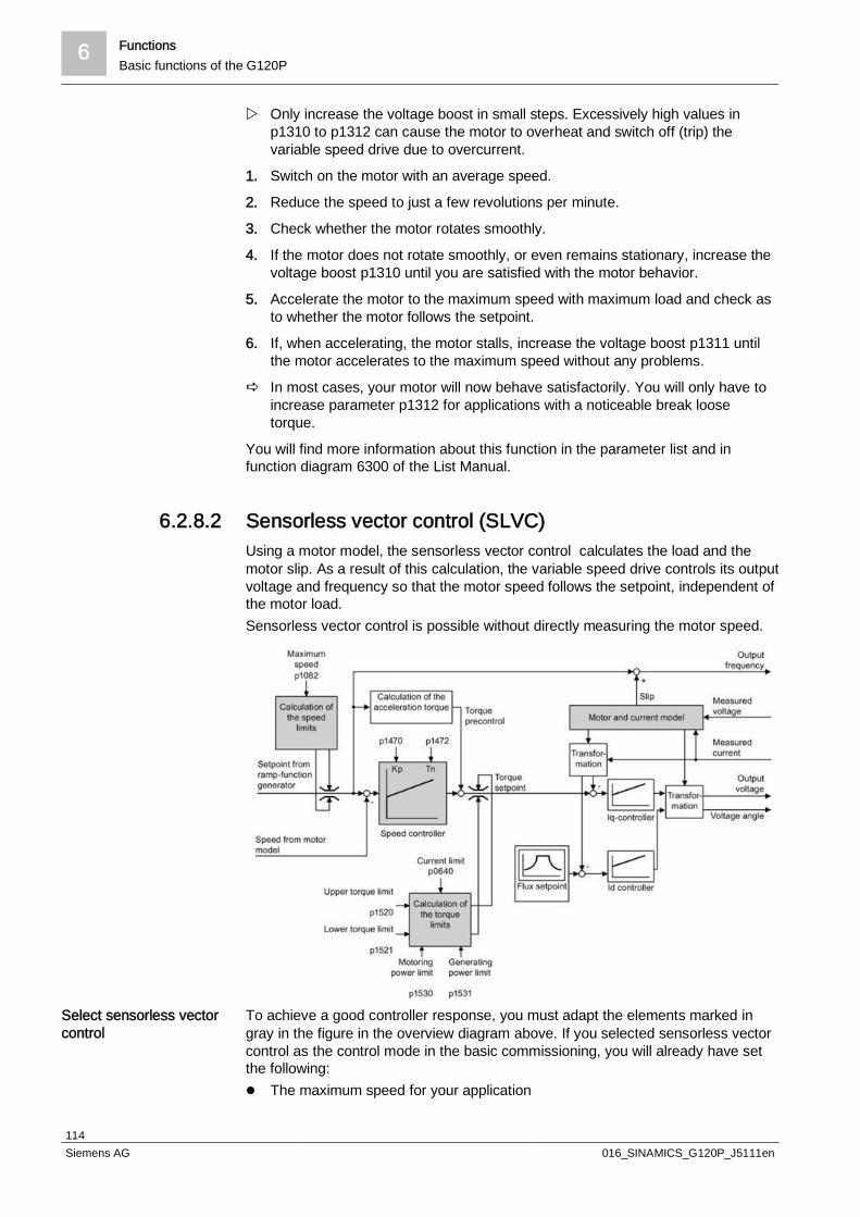
6 FunctionsBasic functions of the G120P
114Siemens AG 016_SINAMICS_G120P_J5111en
w Only increase the voltage boost in small steps. Excessively high values inp1310 to p1312 can cause the motor to overheat and switch off (trip) thevariable speed drive due to overcurrent.
1. Switch on the motor with an average speed.
2. Reduce the speed to just a few revolutions per minute.
3. Check whether the motor rotates smoothly.
4. If the motor does not rotate smoothly, or even remains stationary, increase thevoltage boost p1310 until you are satisfied with the motor behavior.
5. Accelerate the motor to the maximum speed with maximum load and check asto whether the motor follows the setpoint.
6. If, when accelerating, the motor stalls, increase the voltage boost p1311 untilthe motor accelerates to the maximum speed without any problems.
a In most cases, your motor will now behave satisfactorily. You will only have toincrease parameter p1312 for applications with a noticeable break loosetorque.
You will find more information about this function in the parameter list and infunction diagram 6300 of the List Manual.
6.2.8.2 Sensorless vector control (SLVC)Using a motor model, the sensorless vector control calculates the load and themotor slip. As a result of this calculation, the variable speed drive controls its outputvoltage and frequency so that the motor speed follows the setpoint, independent ofthe motor load.Sensorless vector control is possible without directly measuring the motor speed.
To achieve a good controller response, you must adapt the elements marked ingray in the figure in the overview diagram above. If you selected sensorless vectorcontrol as the control mode in the basic commissioning, you will already have setthe following:l The maximum speed for your application
Select sensorless vectorcontrol
Functions 6Basic functions of the G120P
115Siemens AG 016_SINAMICS_G120P_J5111en
l The motor and current model: If the motor data in the variable speed drivecorrespond to the motor data on the rating plate, then the motor and currentmodel in the variable speed drive are correct and the sensorless vector controlcan operate satisfactorily
l The variable speed drive calculates the torque limits matching the current limitthat you have set for the basic commissioning.Regardless of it, you can also set additional positive and negative torque limitsor limit the power of the motor
l The variable speed drive preset the sensorless vector control during self-optimization (rotating measurement)
If you want to optimize the setting further, follow the additional instructions in thissection.Procedure
With operator panel: With STARTER:
l Set p1300 = 20. l Go online with STARTER.l Select "Speed control without encoder" in the
"Speed controller" or "V/f control" screen.
In the following cases you will need to manually optimize the sensorless vectorcontrol:l Your application does not permit self-optimization because the motor cannot
rotate freely.l You are dissatisfied with the result of the variable speed drive's self-
optimization.l The variable speed drive interrupted the self-optimization with a fault message.
6.2.9 Braking functionIf an induction motor electrically brakes the connected load and the mechanicalpower exceeds the electrical losses, then it operates as a generator. The motorconverts mechanical power into electrical power. This may happen in applicationswith large fans, for example.The Power Module PM230 offers the option to convert the generated motor powerinto heat using DC braking.
With DC braking, the variable speed drive outputs an internal OFF2 command forthe time that it takes to demagnetize the motor – and then impresses the brakingcurrent for the duration of the DC braking.
The following operating modes are available for DC braking:
Re-optimizing the speedcontroller
Principle of operation
Operating modes

6 FunctionsBasic functions of the G120P
116Siemens AG 016_SINAMICS_G120P_J5111en
DC braking when the start speed is undershotDC braking is automatically activated as soon as the motor undershoots the startspeed for DC braking. However, the motor speed must have first exceeded thestart speed for DC braking. Once the DC braking time is complete, the variablespeed drive switches to normal operation. If p1230 is set to 0, DC braking can alsobe canceled before the time defined in p1233.
Precondition: p1230 = 1 and p1231 = 14
A2 = DC brake active
DC braking in the event of a faultIf a fault relating to the DC braking occurs (p2101=6), then the variable speed drivefirst brakes the motor along the down ramp until the start speed for DC braking isreached, and then starts DC braking.
Precondition: Fault number and fault response are assigned using p2100 and p2101=6
Sw = Fault presentA2 = DC brake active
Activating DC braking via a control command regardless of the speedDC braking starts regardless of the motor speed s soon as the control commandfor braking (e.g. via DI3: p1230 = 722.3) is issued. If the braking command isrevoked, the variable speed drive returns to normal operation and the motoraccelerates to its setpoint.

Functions 6Basic functions of the G120P
117Siemens AG 016_SINAMICS_G120P_J5111en
The value of p1230 is displayed in r1239.11.
Precondition: p1231 = 4
A1 = DC brake enabledA2 = DC brake active
DC braking when the motor is switched offIf the motor is switched off with OFF1 or OFF3, the variable speed drive first brakesthe motor along the down ramp until the start speed for DC braking is reached, andthen starts DC braking. The motor is then switched into a torque-free condition(OFF2).
Precondition: p1231 = 5 or p1230 = 1 and p1231 = 14
A2 = DC brake active
Continuously turning motorIn the following operating modes, the motor continues to turn after DC braking iscomplete.l DC braking when the start speed for DC braking is undershotl Activating DC braking independent of the speed using a control commandl DC braking when the motor is switched offThe "flying restart" function must therefore be activated in these operating modes.See the Chapter Flying restart [ 119].
The DC braking function can only be set for induction motors.

6 FunctionsBasic functions of the G120P
118Siemens AG 016_SINAMICS_G120P_J5111en
NOTICE
Heat generationDC braking converts some of the kinetic energy of the motor and load into heat inthe motor (temperature rise). The motor will overheat and can be damaged if thebraking operation lasts too long or the motor is braked too often. Avoid braking operations that are too frequent and too long by setting the
parameters accordingly.
Parameters Description
p1230 Activating DC braking (BICO parameter)The value for this parameter (0 or 1) can be either entered directly or specified by meansof an interconnection with a control command.
p1231 Configuring DC brakingp1231 = 0, no DC brakingp1231 = 4, general enabling of DC brakingp1231 = 5, DC braking for OFF1/3, independent of p1230p1231 = 14, enables DC braking for the case that the motor speed undershoots the startspeed for DC braking
Configuring DC braking when faults occur
Parameters Description
p2100 Setting fault number for fault response (factory setting: 0)Enter the fault number for which DC braking should be activated, e.g.: p2100[3] = 7860(external fault 1).
p2101 = 6 Fault response setting (factory setting: 0)Assigning the fault response: p2101[3] = 6.
The fault is assigned an index of p2100. The associated fault response must be assigned the sameindex in p2101.In the List Manual of the variable speed drive – in the "Faults and alarms" list – possible faultresponses are listed for every fault. The entry "DCBRAKE" means that for this particular fault, DCbraking can be set as fault response.
Additional parameters for setting DC braking
Parameters Description
p1232 DC braking, braking current (factory setting: 0 A)Setting the braking current for the DC braking.
p1233 DC braking duration (factory setting: 1 s)
p1234 DC braking start speed (factory setting: 210,000 rpm)DC braking starts – assuming that it has been correspondingly parameterized(p1230/p1231) – as soon as the actual speed falls below this threshold.
p0347 Motor de-excitation timeThe parameter is calculated via p0340 = 1, 3.The inverter can trip due to an overcurrent during DC braking if the de-excitation time istoo short.
Settings

Functions 6Basic functions of the G120P
119Siemens AG 016_SINAMICS_G120P_J5111en
6.2.10 Flying restartIf a variable speed drive is switched on "normally", the motor does not move andthe variable speed drive accelerates the motor from a standstill to the setpointspeed.In many cases, however, the motor rotates at any speed and in any direction, evenwhen it is not driven, for example, in the following situations:l The motor rotates after a brief line interruptionl A flow of air turns the fan impellerl A load with a high moment of inertia drives the motorl A high dynamic pressure allows a pump to run backwardsThe "flying restart" function (p1200) permits the variable speed drive to connect toan unintentionally rotating motor and then captures the motor at its current speedwithout it having to start at zero speed.When starting with a rotating motor, variable speed drives without a flying restartfunction automatically switch off due to overcurrent or cause an excessivemechanical load on the system. This is because they try to bring the rotating motorto zero speed before they accelerate it to the required setpoint.After the ON command, the "flying restart" function initially synchronizes thevariable speed drive output frequency to the motor speed and then accelerates themotor up to the setpoint with normal ramp time.
n = speednw = speed setpointfA = variable speed drive outputfrequencyM = magnetizing motor
The variable speed drive first performs a "standstill check", which means that directcurrent (I DC) is applied for approx. 1 s. This establishes whether the motor is at astandstill or rotating at a speed of more than approx. 10% of the rated speed. If astandstill state is detected, the speed then ramps up as normal.If the motor is rotating, the variable speed drive activates the "flying restart"function and applies a search current (p1202). The frequency initially increases toFmax + 2fslip and the "search" for the actual motor speed begins.Fmax = calculated using the value of p1082.
Method of operation

6 FunctionsBasic functions of the G120P
120Siemens AG 016_SINAMICS_G120P_J5111en
2fslip = uses an internal calculation that shows the difference between a motor'ssynchronous speed (e.g. 1,500 rpm for a 4-pole motor) and its actual rated speed(defined in p0311, e.g. 1,480 rpm). In this example, the slip would be 1.3%.
The "search speed" is defined by the value defined inp1203. If the output frequency (foff) drops, the G120Pdetermines that it has found the actual motor speed when itdetects a reduction in the motor magnet field, i.e. when themotor voltage increases (Voff). The G120P then returns to astandard V/f characteristic and controls the motor speedback to the setpoint.If the motor speed is not found due to the motor rotating inthe opposite direction, the search sequence is repeated inthe other direction, although the p1200 must be set to thevalue of 1 for this. Setting 4 only searches in the direction ofthe variable speed drive's setpoint (forwards or backwards).If the motor is programmed so that it only searches in onedirection and there is a possibility that the motor is rotating inboth directions, the variable speed drive can respond to asudden overcurrent. The G120P may display the A07409alarm (current limit) or even switch off due to fault F07801(overcurrent).
Parameters Description
p1200 Flying restart operating mode (factory setting: 0)
01
4
Flying restart is disabledFlying restart is enabled, motor search performed in both directions,startup in direction of setpointFlying restart is enabled, search performed in direction of setpoint only
p1201 Flying restart enable signal source (factory setting: 1)Defines a control command, e.g. a digital input, through which the flying restart functionis enabled.
p1201 Flying restart search current (factory setting: 90 %)Defines the search current with respect to the motor magnetizing current (r0331), whichflows in the motor while the flying restart function is being used.
p1203 Flying restart search speed factor (factory setting: 150 %)The value influences the speed with which the output frequency is changed during theflying restart. A higher value leads to a longer search time.If the variable speed drive does not find the motor, reduce the search speed (increasep1203).
w To activate the "flying restart" function, simply set the p1200 parameter to avalue other than 0.Determine the required setting for p1200 using the following questions:
1. Decide whether the flying restart is necessary. Is it possible for the motor torotate before the G120P operation is activated? If yes, the "flying restart"function should be activated.
2. Is it possible for the motor to rotate in both directions? If yes, p1200 should beset to 1. Although this generally applies to fans, a pump with a high deliveryhead in a system without non-return valves could rotate in the oppositedirection before starting the variable speed drive.
3. If the "automatic restart" function (p1210) has been activated, the "flyingrestart" function should also be activated. In the event of a power failure ordisconnection when the automatic restart is active, it is possible for the G120Pto start back up while the motor is still running down. If this should occur,activate p1200 with setting 1. The p1200=1 setting means that the G120Pactivates the "flying restart" function if the previous stop command was OFF1
Settings
Setting up the "flyingrestart" function

Functions 6Basic functions of the G120P
121Siemens AG 016_SINAMICS_G120P_J5111en
(normal braking to a standstill) or a shutdown, fault state, OFF2 (run down tostandstill), or OFF3.
4. The p1200=4 setting corresponds to the value 1, although the search is onlyperformed in one direction.
After you have determined the required setting for p1200, you may have to adaptthe parameters p1202 and p1203 to ensure that the G120P captures the rotatingmotor without the mechanical load on the drive mechanics being too high.The standard setting for p1202 is 90%, p1203 is set to 150%. In certainapplications, this can mean that loads are too high for the G120P. In certainapplications, leaving the factory settings as they are can result in the G120Pshutting down due to overcurrent. If a fault or warning is displayed during startupwith an activated "flying restart" function, the p1202/p1203 parameters may have tobe adapted.
w All applications are different and the inertia of every load varies. The followinginformation is for orientation purposes only.Before you begin, first set p1200 to the correct setting for your application.
1. Check the behavior of the "flying restart" function (i.e. ensure that it does notcause excessive loads) by activating the restart at approx. 60% of the fullspeed.
2. Without a speed counter, it can be difficult to establish the actual motor speed.A simple way to check is to accelerate the motor to full speed then activate arun down to standstill, measuring the time it takes for the motor to come to astop. If the motor requires 30 s to come to a standstill, for example, it runs atapprox. 60% of the speed after 12 s.
3. You can activate the run down to standstill as follows: This function can beprogrammed for one of the reserve digital inputs if it is not already available inyour system. To do this, program the "Run down to standstill" function at one ofthe digital inputs (digital input 3 [terminal 8], for example, would be p0844 =r722.3) and establish a connection between terminal 9 and this digital input(terminal 8 in this example).Before the restart can take place, the "Run down to standstill" switch must beclosed to allow the RUN signal to be sent.
w A simple sequence could be as follows:
1. Accelerate the motor to maximum speed.
2. Activate a run down to standstill.
- For this, open 9-8 in the example described.- Close the switch again between 9-8.- Activate the RUN signal after 12 s via (usually) terminals 5-9.
3. After the RUN signal has been applied, the output frequency increases rapidlyand the current increases. Ensure that the current does not increase too muchduring this restart period. If the warning A07409 is displayed then p1202 is setto a value that is too high.
4. The simplest method is to set the BOP-2 (basic operator panel) to currentmonitoring. You can then see how the ampere value changes during the flyingrestart. If you reduce p1202 by 90% (we recommend steps of 10% to aminimum of 50%), the current drops with every check. If the current drops too
6 FunctionsBasic functions of the G120P
122Siemens AG 016_SINAMICS_G120P_J5111en
significantly, this can affect the "flying restart duration", which in turn affects theeffectivity of the flying restart.
5. In larger motors (>30 kW) and motors with high efficiency, the motor slipdecreases. For these motors, it is sometimes advisable to increase the searchtime (p1203) (in steps of 10% again).
6. By completing these two processes step-by-step and checking the effects afterevery change, you should be able to make optimal adjustments to the flyingrestart, i.e. a lower current demand yet with the motor speed reached quickly.
If the variable speed drive simultaneously drives several motors, then you mustonly use the "flying restart" function if all motors run at the same speed (groupdrive with a mechanical coupling).
For systems with large moments of inertia, the default settings for the "flyingrestart" function can lead to disconnections due to overcurrent. You can rectify thisby changing flying restart parameters p1202 (search current) and p1203 (searchspeed).
6.2.11 Automatic restart
WARNING
Automatic restartWhen the automatic restart function is active (p1210 > 1), the motor automaticallystarts after a power failure. Particularly after longer power failures, the restart maytake place unexpectedly for a person on-site. Reduce the risk of accidents due to unexpected restarts in your machine or
system by applying suitable measures, e.g. protective doors or covers.
The automatic restart includes two different functions:l The variable speed drive automatically acknowledges faults.l After a fault occurs or after a power failure, the variable speed drive
automatically switches on the motor again.This automatic restart function is primarily used in applications where the motor iscontrolled locally via the variable speed drive's inputs. In applications with aconnection to a fieldbus, the central control should evaluate the feedback signals ofthe drives, specifically acknowledge faults or switch on the motor.The variable speed drive interprets the following events as power failure:l The variable speed drive signals fault F30003 (DC-link undervoltage), as the
line supply voltage of the variable speed drive has briefly failed.l The variable speed drive power supply has failed for such a long time that the
variable speed drive has been switched off.
l If it is possible that the motor is still rotating for a longer period of time after apower failure or after a fault, then you must also activate the "flying restart"function.
l Using p1210, select the automatic restart mode that best suits your application.We recommend setting 26 for HVAC systems.
Systems with a momentof inertia
Setting the automaticrestart

Functions 6Basic functions of the G120P
123Siemens AG 016_SINAMICS_G120P_J5111en
WARNING
Automatic restart in the event of no communication with the fieldbusWhen connecting the variable speed drive to a fieldbus and setting p1210 = 6, themotor restarts – even if the communication to the fieldbus is interrupted. Themotor cannot be stopped via the interrupted fieldbus. Prevent unwanted restarts in the event of missing bus communication by
entering the fault code for the communication error into parameter p1206.Example: A communication failure via USS, Modbus, or BACnet MS/TP issignaled using fault code F01910. You should therefore set p1206[n] = 1910(n = 0 to 9).
Parameters Description
p1210 Automatic restart mode (factory setting: 0)
0 Disables automatic restart
1 Acknowledges all faults without restarting
4 Automatic restart after line supply failure, without additional startup attempts
6 Restart after fault, with additional startup attempts
14 Restart after line supply failure, after manual acknowledgement
16 Restart after fault, after manual acknowledgement
26 Acknowledges all faults and restarts for an ON command (recommendedsetting for HVAC systems)
p1211 Automatic restart start attempts (factory setting: 3)This parameter is only effective for the settings p1210 = 4, 6, 14, 16, 26.Define the maximum number of start attempts using p1211. After each successfulfault acknowledgement, the variable speed drive decrements its internal counter ofstart attempts by 1.For p1211 = n, up to n + 1 start attempts are made. Fault F07320 is output after n + 1unsuccessful start attempts.The variable speed drive sets the start attempt counter back again to the value ofp1211 if one of the following conditions is fulfilled:l After a successful start attempt, the time in p1213[1] has expired.l After fault F07320, withdraw the ON command and acknowledge the fault.l You change the start value p1211 or the mode p1210.
p1212 Automatic restart wait time start attempt (factory setting: 1 s)This parameter is only effective for the settings p1210 = 4, 6, 26.Examples for setting this parameter:l After a power failure, a certain time must elapse before the motor can be
switched on, e.g. because other machine components are not immediately ready.In this case, set p1212 longer than the time after which all of the fault causeshave been removed.
l In operation, the variable speed drive develops a fault condition. The lower youselect p1212, then the sooner the variable speed drive attempts to switch on themotor again.
p1213[0] Automatic restart monitoring time for restart (factory setting: 60 s)This parameter is only effective for the settings p1210 = 4, 6, 14, 16, 26.With this monitoring function, you limit the time in which the variable speed drive mayattempt to automatically switch on the motor again.The monitoring function starts when a fault is identified and ends with a successfulstart attempt. If the motor has not successfully started after the monitoring time hasexpired, fault F07320 is signaled.Set the monitoring time longer than the sum of the following times:+ p1212+ Time that the variable speed drive requires to start the motor on the fly.

6 FunctionsBasic functions of the G120P
124Siemens AG 016_SINAMICS_G120P_J5111en
Parameters Description
+ Motor magnetizing time (p0346)+ 1 sYou deactivate the monitoring function with p1213 = 0.
p1213[1] Automatic restart monitoring time to reset the fault counter (factory setting: 0 s)This parameter is only effective for the settings p1210 = 4, 6, 14, 16, 26.Using this monitoring time, you prevent faults, which continually occur within a certaintime period, from being automatically acknowledged each time.The monitoring function starts with a successful start attempt and ends after themonitoring time has expired.If the variable speed drive has made more than (p1211 + 1) successful start attemptswithin monitoring time p1213[1], it cancels the automatic restart function and signalsfault F07320. In order to switch on the motor again, you must acknowledge the faultand issue a new ON command.
If you wish to suppress the automatic restart function for certain faults, then youmust enter the appropriate fault numbers in p1206[0 to 9].Example: p1206[0] = 07331 ⇒ No restart for fault F07331.Suppressing the automatic restart only functions for the setting p1210 = 6, 16 or26.
6.2.12 Data backup and standard commissioningAfter commissioning and copying the data into the variable speed drive's ROM(EEprom), your settings are saved in the variable speed drive and protectedagainst power failure.
NOTICE
Defects in the variable speed driveIn the case of a defect in the variable speed drive, your settings may be lost. In addition, you should also save the parameters on a storage medium
outside the variable speed drive.
The following storage media are available for your settings:l Memory cardl PC/PG (via STARTER software)l Operator panel
w Series commissioning is the commissioning of several identical drives. Aftercommissioning of the first drive, you must do the following:
1. Back up the settings of the first variable speed drive to an external storagemedium.
2. Transfer the settings of the first variable speed drive to another one via thestorage medium.
The Control Unit to which the parameters are transferred must have the sameorder number and the same or a higher firmware version as the source ControlUnit.
Advanced settings
External data backup
Series commissioning

Functions 6Basic functions of the G120P
125Siemens AG 016_SINAMICS_G120P_J5111en
6.2.12.1 Backing up and transferring settings using a memory cardWe recommend that you use one of the memory cards with the following ordernumber:l MMC (order number 6SL3254-0AM00-0AA0)Alternatively, you can also use MMC or standard SD cards up to 2 GB. SDHC,SDXC, or other special types of SD cards are not supported.
If you use SD or MMC memory cards from other manufacturers, then you mustformat the memory card as follows:
w MMC: Format FAT 16
1. Insert the card into your PC's card reader.
2. Command to format the card:format x: /fs:fat (x: Drive code of the memory card on your PC)
w SD: Format FAT 32
1. Insert the card into your PC's card reader.
2. Command to format the card:format x: /fs:fat32 (x: Drive code of the memory card on your PC)
Memory cards from third-party manufacturers do not support all functions, e.g. fordownloading. The use of memory cards from other manufacturers is at your ownrisk.
Saving setting on a memory cardWe recommend that you insert the memory card before switching on the variablespeed drive.
Ensure that your variable speed drive is not connected to the computer via USB,otherwise the memory card will be recognized by Windows as a USB massstorage drive and locked for use by the variable speed drive.
The variable speed drive always also backs up its settings on an inserted card.If you wish to backup the variable speed drive settings on a memory card, youhave two options:
w The variable speed drive power supply is switched off.
1. Insert an empty memory card into the variable speed drive.
2. Then switch on the variable speed drive power supply.
Recommended memorycards
Other memory cards
6.2.12.1.1
Automatic backup
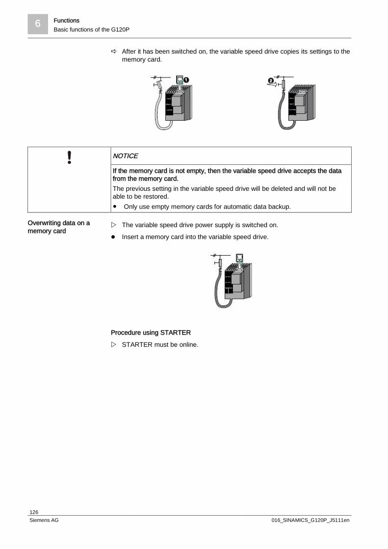
6 FunctionsBasic functions of the G120P
126Siemens AG 016_SINAMICS_G120P_J5111en
a After it has been switched on, the variable speed drive copies its settings to thememory card.
NOTICE
If the memory card is not empty, then the variable speed drive accepts the datafrom the memory card.The previous setting in the variable speed drive will be deleted and will not beable to be restored. Only use empty memory cards for automatic data backup.
w The variable speed drive power supply is switched on.
l Insert a memory card into the variable speed drive.
Procedure using STARTER
w STARTER must be online.
Overwriting data on amemory card

Functions 6Basic functions of the G120P
127Siemens AG 016_SINAMICS_G120P_J5111en
1. In your drive, select "Drive Navigator".
2. Select the "Commissioning" button.
3. Select the button to transfer the settings to the memory card.
4. Select the settings as shown in the diagram and start the data backup.
Procedure with the BOP-2
l Start data transfer in the menu "OPTIONS" – "TO CRD".
Procedure with IOP
1. Choose the Menu option using the rotary knob and confirm with OK.
2. Select the Up/Download setting and confirm with OK.
3. Select From drive to memory card and confirm with OK.
a "Select parameter set on memory card" appears on the display.
4. Select the required number for the parameter set and confirm with OK.
a "The parameter up/download will take some time and cannot be cancelled"appears on the display.
5. Select Continue and confirm with OK (the option to cancel is also available).
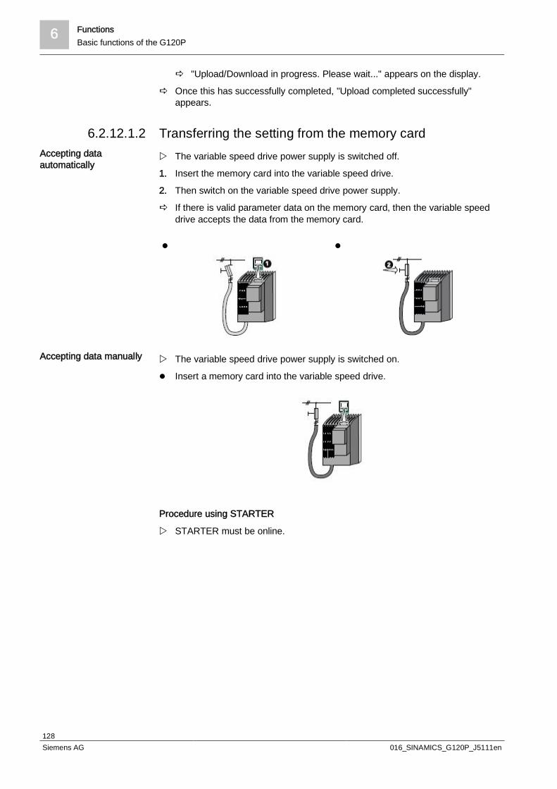
6 FunctionsBasic functions of the G120P
128Siemens AG 016_SINAMICS_G120P_J5111en
a "Upload/Download in progress. Please wait..." appears on the display.
a Once this has successfully completed, "Upload completed successfully"appears.
Transferring the setting from the memory cardw The variable speed drive power supply is switched off.
1. Insert the memory card into the variable speed drive.
2. Then switch on the variable speed drive power supply.
a If there is valid parameter data on the memory card, then the variable speeddrive accepts the data from the memory card.
l l
w The variable speed drive power supply is switched on.
l Insert a memory card into the variable speed drive.
Procedure using STARTER
w STARTER must be online.
6.2.12.1.2Accepting dataautomatically
Accepting data manually
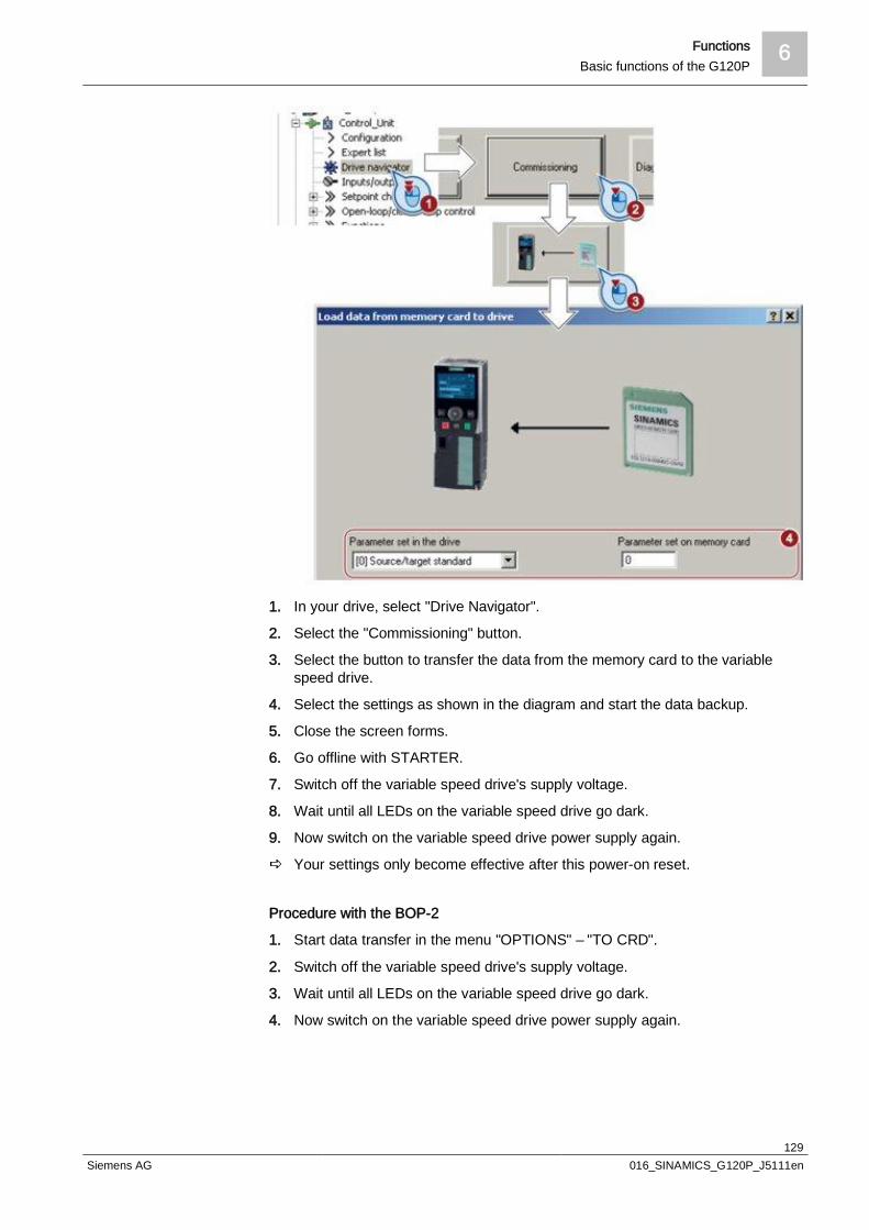
Functions 6Basic functions of the G120P
129Siemens AG 016_SINAMICS_G120P_J5111en
1. In your drive, select "Drive Navigator".
2. Select the "Commissioning" button.
3. Select the button to transfer the data from the memory card to the variablespeed drive.
4. Select the settings as shown in the diagram and start the data backup.
5. Close the screen forms.
6. Go offline with STARTER.
7. Switch off the variable speed drive's supply voltage.
8. Wait until all LEDs on the variable speed drive go dark.
9. Now switch on the variable speed drive power supply again.
a Your settings only become effective after this power-on reset.
Procedure with the BOP-2
1. Start data transfer in the menu "OPTIONS" – "TO CRD".
2. Switch off the variable speed drive's supply voltage.
3. Wait until all LEDs on the variable speed drive go dark.
4. Now switch on the variable speed drive power supply again.

6 FunctionsBasic functions of the G120P
130Siemens AG 016_SINAMICS_G120P_J5111en
a Your settings only become effective after this power-on reset.
Procedure with IOP
1. Choose the Menu option using the rotary knob and confirm with OK.
2. Select the Up/Download setting and confirm with OK.
3. Select From memory card to drive and confirm with OK.
a "Select parameter set on memory card" appears on the display.
4. Select the number for the required parameter set and confirm with OK.
a "The parameter up/download will take some time and cannot be cancelled"appears on the display.
5. Select Continue and confirm with OK (the option to cancel is also available).
a "Upload/Download in progress. Please wait..." appears on the display.
a Once this has successfully completed, "Download completed successfully.Remove the memory card and reboot the drive" appears.
Safely removing the memory card
NOTICE
Removing the memory card incorrectlyThe file system on the memory card can be destroyed if the memory card isremoved while the variable speed drive is switched on without first requesting andconfirming this using the "remove safely" function. The memory card will then nolonger function. Always select "remove safely" before removing the memory card.
Procedure using STARTER
1. In the Drive Navigator, select the following screen form:
6.2.12.1.3
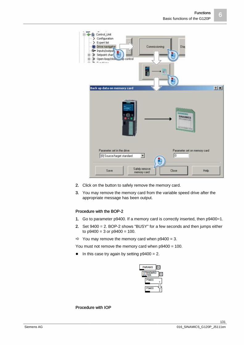
Functions 6Basic functions of the G120P
131Siemens AG 016_SINAMICS_G120P_J5111en
2. Click on the button to safely remove the memory card.
3. You may remove the memory card from the variable speed drive after theappropriate message has been output.
Procedure with the BOP-2
1. Go to parameter p9400. If a memory card is correctly inserted, then p9400=1.
2. Set 9400 = 2. BOP-2 shows "BUSY" for a few seconds and then jumps eitherto p9400 = 3 or p9400 = 100.
a You may remove the memory card when p9400 = 3.
You must not remove the memory card when p9400 = 100.
l In this case try again by setting p9400 = 2.
Procedure with IOP
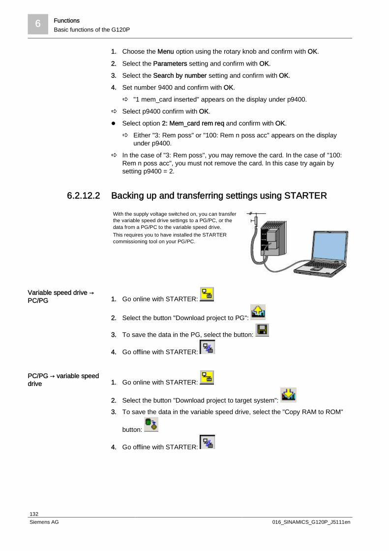
6 FunctionsBasic functions of the G120P
132Siemens AG 016_SINAMICS_G120P_J5111en
1. Choose the Menu option using the rotary knob and confirm with OK.
2. Select the Parameters setting and confirm with OK.
3. Select the Search by number setting and confirm with OK.
4. Set number 9400 and confirm with OK.
a "1 mem_card inserted" appears on the display under p9400.
a Select p9400 confirm with OK.
l Select option 2: Mem_card rem req and confirm with OK.
a Either "3: Rem poss" or "100: Rem n poss acc" appears on the displayunder p9400.
a In the case of "3: Rem poss", you may remove the card. In the case of "100:Rem n poss acc", you must not remove the card. In this case try again bysetting p9400 = 2.
6.2.12.2 Backing up and transferring settings using STARTER
With the supply voltage switched on, you can transferthe variable speed drive settings to a PG/PC, or thedata from a PG/PC to the variable speed drive.This requires you to have installed the STARTERcommissioning tool on your PG/PC.
1. Go online with STARTER:
2. Select the button "Download project to PG":
3. To save the data in the PG, select the button:
4. Go offline with STARTER:
1. Go online with STARTER:
2. Select the button "Download project to target system":3. To save the data in the variable speed drive, select the "Copy RAM to ROM"
button:
4. Go offline with STARTER:
Variable speed drive →PC/PG
PC/PG → variable speeddrive

Functions 6Basic functions of the G120P
133Siemens AG 016_SINAMICS_G120P_J5111en
6.2.12.3 Backing up and transferring settings using an operator
panel
When the power supply is switched on, you can transfer the settings of thevariable speed drive to the BOP-2 or vice versa.
l Start data transfer in the menu "OPTIONS" – "TO BOP".
1. Start data transfer in the menu "OPTIONS" – "FROM BOP".
a In FW version 4.6, this completes the transfer. In FW versions < 4.6, youmust also complete the following steps:
2. Switch off the variable speed drive's supply voltage.
3. Wait until all LEDs on the variable speed drive go dark.
4. Now switch on the variable speed drive power supply again.
a Your settings only become effective after this power-on reset.
1. Choose the Menu option using the rotary knob and confirm with OK.
2. Select the Up/Download setting and confirm with OK.
3. Select Upload from drive and confirm with OK.
a The list of panel parameter sets 0-15 appears on the display.
4. Select the number of the panel parameter set to which you want to save thedata and confirm with OK.
a "Running" appears on the display and a bar shows the progress. You cancancel this using "ESC".
a Once this has successfully completed, "Upload complete" appears.
1. Choose the Menu option using the rotary knob and confirm with OK.
2. Select the Up/Download setting and confirm with OK.
3. Select Download to drive and confirm with OK.
a A list of the available panel parameter sets appears on the display.
4. Select the number of the panel parameter set that you want to save to thevariable speed drive and confirm with OK.
Procedure for variablespeed drive → BOP-2
Procedure for BOP-2 →variable speed drive
Procedure for variablespeed drive → IOP
Procedure for IOP →variable speed drive
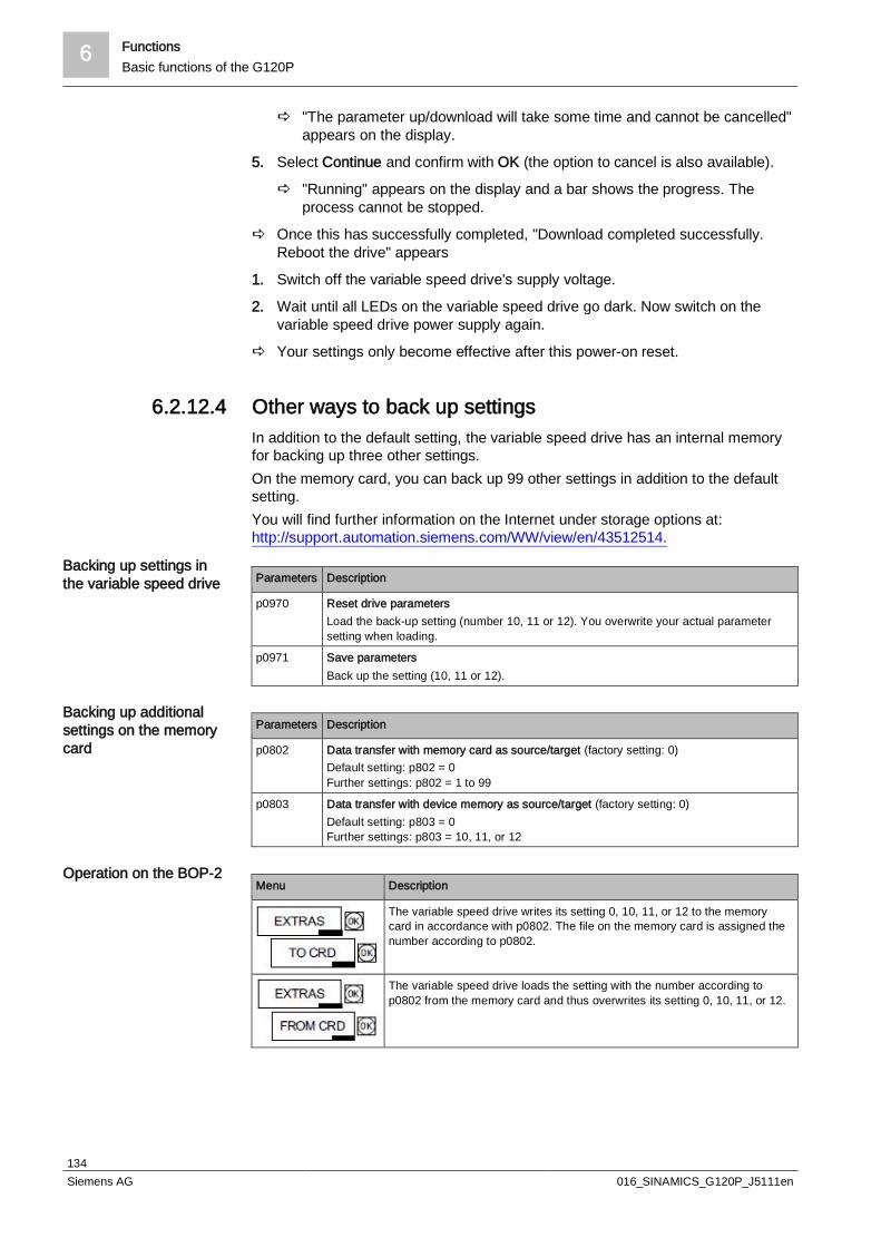
6 FunctionsBasic functions of the G120P
134Siemens AG 016_SINAMICS_G120P_J5111en
a "The parameter up/download will take some time and cannot be cancelled"appears on the display.
5. Select Continue and confirm with OK (the option to cancel is also available).
a "Running" appears on the display and a bar shows the progress. Theprocess cannot be stopped.
a Once this has successfully completed, "Download completed successfully.Reboot the drive" appears
1. Switch off the variable speed drive's supply voltage.
2. Wait until all LEDs on the variable speed drive go dark. Now switch on thevariable speed drive power supply again.
a Your settings only become effective after this power-on reset.
6.2.12.4 Other ways to back up settingsIn addition to the default setting, the variable speed drive has an internal memoryfor backing up three other settings.On the memory card, you can back up 99 other settings in addition to the defaultsetting.You will find further information on the Internet under storage options at:http://support.automation.siemens.com/WW/view/en/43512514.
Parameters Description
p0970 Reset drive parametersLoad the back-up setting (number 10, 11 or 12). You overwrite your actual parametersetting when loading.
p0971 Save parametersBack up the setting (10, 11 or 12).
Parameters Description
p0802 Data transfer with memory card as source/target (factory setting: 0)Default setting: p802 = 0Further settings: p802 = 1 to 99
p0803 Data transfer with device memory as source/target (factory setting: 0)Default setting: p803 = 0Further settings: p803 = 10, 11, or 12
Menu Description
The variable speed drive writes its setting 0, 10, 11, or 12 to the memorycard in accordance with p0802. The file on the memory card is assigned thenumber according to p0802.
The variable speed drive loads the setting with the number according top0802 from the memory card and thus overwrites its setting 0, 10, 11, or 12.
Backing up settings inthe variable speed drive
Backing up additionalsettings on the memorycard
Operation on the BOP-2

Functions 6Basic functions of the G120P
135Siemens AG 016_SINAMICS_G120P_J5111en
6.2.13 Write and know-how protectionThe variable speed drive offers the option to protect configured settings from beingchanged or copied.Write protection and know-how protection are available for this purpose.
Write protection prevents variable speed drive settings from being inadvertentlychanged. No password is required for write protection. There is no encryption.The following functions are excluded from the write protection:l Activating/deactivating write protection (p7761)l Changing the access level (p0003)l Saving parameters (p0971)l Safely removing the memory card (p9400)l Access to service parameters (p3950) – only for service personnel, a password
is requiredl Restoring the factory settingl Uploadl Acknowledging alarms and faultsl Switching over to the control panell Tracel Function generatorl Measuring functionsl Reading out diagnostic bufferThe individual parameters that are excluded from the write protection, can be foundin the List Manual in Chapter "Parameters for write protection and protection ofknow-how".
w To allow you to set write protection, your variable speed drive must beconnected online with STARTER.
1. Select the variable speed drive in your STARTER project with the left mousebutton.
2. Open the shortcut menu by right-clicking.
3. Activate write protection.
Deactivation is executed in analog.To make this setting permanent, you need to copy the settings from RAM to ROM.Otherwise, your settings will be lost when the variable speed drive is switched off.
Write protection –overview
Setting the writeprotection

6 FunctionsBasic functions of the G120P
136Siemens AG 016_SINAMICS_G120P_J5111en
The know-how protection is used, for example, so that a machine manufacturercan encrypt his configuration know-how and protect it against changes or copying.The know-how protection is available in the following versions:l Know-how protection without copy protection (possible with or without memory
card)l Know-how protection with copy protection (possible only with Siemens memory
card)A password is required for the know-how protection.In case of active know-how protection, the STARTER dialog screens are locked.You can, however, read the values of the display parameters from the expert list.The values of the adjustment parameters are not displayed and cannot bechanged.
Actions that are also possible during active know-how protectionl Restoring factory settingsl Acknowledging messagesl Displaying messagesl Displaying the alarm historyl Reading out diagnostic bufferl Switching to the control panel (complete control panel functionality: Fetching
master control, all buttons and setting parameters)l Upload (only parameters that are accessible even though know-how protection
is active)
Actions that are not possible during active know-how protectionl Downloadl Export/importl Tracel Function generatorl Measuring functionsl Automatic controller settingl Stationary/rotating measurementl Deleting the alarm historyThe parameters that are excluded from the know-how protection can be found inthe List Manual in Chapter "Parameters for write protection and protection of know-how".
Creating an exception list for the know-how protectionUsing the exception list, you as a machine manufacturer may make individualadjustable parameters accessible to end customers although know-how protectionis active. You may define the exception list via parameters p7763 and p7764 in theexpert list. Specify the number of parameters for the selection list in p7763. Assignthe individual indexes to the parameter numbers of the selection list in p7764.Factory setting for the exception list:l p7763 = 1 (selection list contains precisely one parameter)l p7764[0] = 7766 (parameter number for entering the password)
Know-how protection –overview
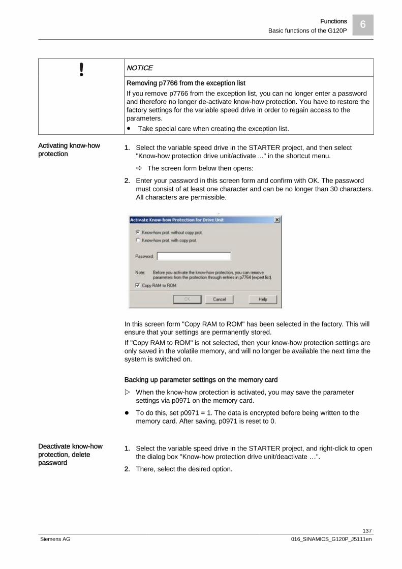
Functions 6Basic functions of the G120P
137Siemens AG 016_SINAMICS_G120P_J5111en
NOTICE
Removing p7766 from the exception listIf you remove p7766 from the exception list, you can no longer enter a passwordand therefore no longer de-activate know-how protection. You have to restore thefactory settings for the variable speed drive in order to regain access to theparameters. Take special care when creating the exception list.
1. Select the variable speed drive in the STARTER project, and then select"Know-how protection drive unit/activate ..." in the shortcut menu.
a The screen form below then opens:
2. Enter your password in this screen form and confirm with OK. The passwordmust consist of at least one character and can be no longer than 30 characters.All characters are permissible.
In this screen form "Copy RAM to ROM" has been selected in the factory. This willensure that your settings are permanently stored.If "Copy RAM to ROM" is not selected, then your know-how protection settings areonly saved in the volatile memory, and will no longer be available the next time thesystem is switched on.
Backing up parameter settings on the memory card
w When the know-how protection is activated, you may save the parametersettings via p0971 on the memory card.
l To do this, set p0971 = 1. The data is encrypted before being written to thememory card. After saving, p0971 is reset to 0.
1. Select the variable speed drive in the STARTER project, and right-click to openthe dialog box "Know-how protection drive unit/deactivate …".
2. There, select the desired option.
Activating know-howprotection
Deactivate know-howprotection, deletepassword

6 FunctionsBasic functions of the G120P
138Siemens AG 016_SINAMICS_G120P_J5111en
3. Enter the password and exit the screen form with OK.
Deactivating know-how protection temporarilyTemporarily deactivating the know-how protection means that you can change thesettings in the variable speed drive until you switch the variable speed drive off andon again, or until you reactivate the know-how protection.
Permanently deactivating know-how protection (deleting password)Permanently deactivating the know-how protection means that you delete thepassword:l Immediately and finally, if you select "Copy RAM to ROM"l Until the next OFF/ON if you do not select "Copy RAM to ROM"
Changing the passwordSelect the variable speed drive in the STARTER project and open the dialog boxvia the shortcut menu "Know-how protection drive unit/change password …".
6.2.14 Factory settings
6.2.14.1 Using the factory settingsw You only have to do the following if the factory settings of the variable speed
drive match your motor and your application.
l Connect the variable speed drive in accordance with the wiring example.
w If you operate the drive on a fieldbus, you have to do the following:
1. Configure your central controller according to the settings of the variable speeddrive.
2. If required by the fieldbus, set the bus address on the variable speed drive.
6.2.14.2 Factory setting of the variable speed drive controlThe variable speed drives are set in the factory so that after it has been switchedon, the motor accelerates in 10 s (based on 1,500 rpm) up to its speed setpoint.After it has been switched off, the motor brakes with a ramp-down time of 30seconds. See also AC motors [ 20] and Motor selection [ 44].
Switching the motor onand off

Functions 6Basic functions of the G120P
139Siemens AG 016_SINAMICS_G120P_J5111en
You can set the required open-loop/closed-loop operating mode in control barp1300. The V/f control with parabolic characteristic is set as standard (setting 2).See V/f control [ 111].
6.2.14.3 Pre-assignment of the control terminalsMany applications already function using the factory settings.The following wiring can be used for Control Units which receive their commandsand setpoints via control terminals (CU230P-2 BT and CU230P-2 CAN) to use thefactory setting.
CU230P-2 BT and CU230P-2 CAN (CANopen)
Open-loop/closed-loopcontrol operating mode
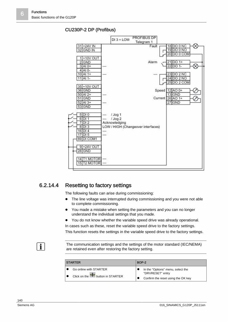
6 FunctionsBasic functions of the G120P
140Siemens AG 016_SINAMICS_G120P_J5111en
CU230P-2 DP (Profibus)
6.2.14.4 Resetting to factory settingsThe following faults can arise during commissioning:l The line voltage was interrupted during commissioning and you were not able
to complete commissioning.l You made a mistake when setting the parameters and you can no longer
understand the individual settings that you made.l You do not know whether the variable speed drive was already operational.In cases such as these, reset the variable speed drive to the factory settings.This function resets the settings in the variable speed drive to the factory settings.
The communication settings and the settings of the motor standard (IEC/NEMA)are retained even after restoring the factory setting.
STARTER BOP-2
l Go online with STARTER
l Click on the button in STARTER
l In the "Options" menu, select the"DRVRESET" entry
l Confirm the reset using the OK key

Functions 6HVAC functions of the G120P
141Siemens AG 016_SINAMICS_G120P_J5111en
6.3 HVAC functions of the G120PThe following table provides an overview of the HVAC functions described in thissection. The short description allows you to decide whether or not you require thecorresponding function as part of the project.
Segment Short description Required in theproject
Yes No
PID controller [ 141] PID controller functions and settings forcontrolling the speed using HVAC-specificprocess variables
Real time clock (RTC) [ 143] The real time clock sets time stamps forevents in the controller, such as faultmessages, alarms, or a reminder for themotor/fan service
Time switch (DTC) [ 144] The time switch is for time-related openloop/closed loop control of the speed forday/night or weekday/weekend, for example
Connection for temperature sensors[ 145]
Permissible temperature sensors, connectionto the analog inputs and their settings
Cascading pumps or fans [ 146] Several graded pumps/fans that can beswitched on and off to cover widemass/volume flows or pressure ranges
Connecting several motors [ 149] Conditions for connecting several motorsoperated in parallel
Multi-zone control [ 150] Minimum, maximum, or mean value control ofseveral setpoint or actual values from variouszones
Energy-saving mode (hibernationmode) [ 153]
Switches the motor off by means of severalcriteria to save energy as soon as a definablelower limit is reached
Bypass (bypassing the variablespeed drive) [ 156]
Variable speed drive behavior in definableframework conditions, for example atmaximum motor power or if the variablespeed drive should fail
Torque monitoring [ 181] Constant torque monitoring to detectdeviations, for example due to a lack of flow,a torn V-belt, or faulty ball bearings
Essential Service Mode(fire/emergency operation) [ 183]
Operating mode to maintain emergencyfunctions for as long as possible, for examplestairwell ventilation in the event of a fire
6.3.1 PID controllerThe G120P has an integrated PID technology controller for controlling the speedusing HVAC-specific process variables such as pressure, temperature, level, orflow.This enables you to establish independent application control without additionalcontrollers.
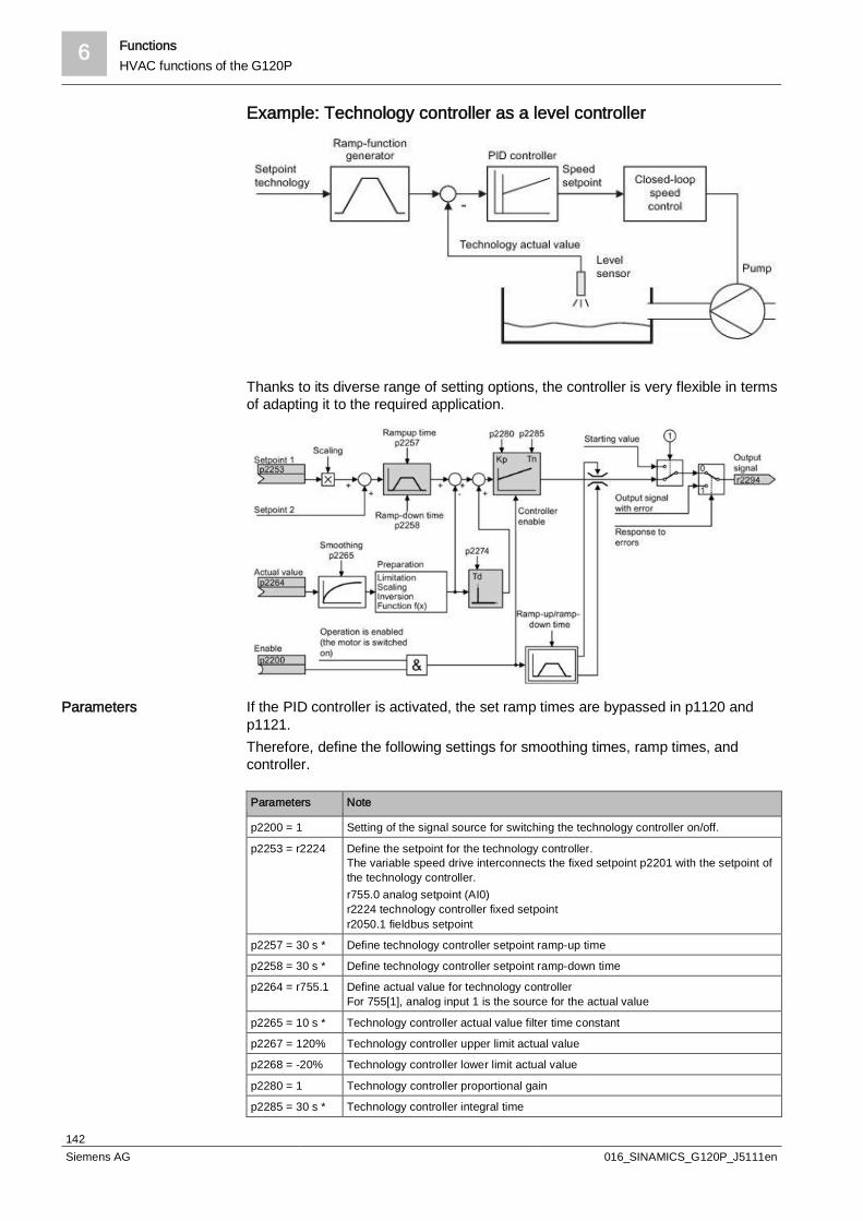
6 FunctionsHVAC functions of the G120P
142Siemens AG 016_SINAMICS_G120P_J5111en
Example: Technology controller as a level controller
Thanks to its diverse range of setting options, the controller is very flexible in termsof adapting it to the required application.
If the PID controller is activated, the set ramp times are bypassed in p1120 andp1121.Therefore, define the following settings for smoothing times, ramp times, andcontroller.
Parameters Note
p2200 = 1 Setting of the signal source for switching the technology controller on/off.
p2253 = r2224 Define the setpoint for the technology controller.The variable speed drive interconnects the fixed setpoint p2201 with the setpoint ofthe technology controller.r755.0 analog setpoint (AI0)r2224 technology controller fixed setpointr2050.1 fieldbus setpoint
p2257 = 30 s * Define technology controller setpoint ramp-up time
p2258 = 30 s * Define technology controller setpoint ramp-down time
p2264 = r755.1 Define actual value for technology controllerFor 755[1], analog input 1 is the source for the actual value
p2265 = 10 s * Technology controller actual value filter time constant
p2267 = 120% Technology controller upper limit actual value
p2268 = -20% Technology controller lower limit actual value
p2280 = 1 Technology controller proportional gain
p2285 = 30 s * Technology controller integral time
Parameters

Functions 6HVAC functions of the G120P
143Siemens AG 016_SINAMICS_G120P_J5111en
Parameters Note
p2293 = 30 s * Technology controller ramp-up/ramp-down time
p2306 = 0 Technology controller fault-signal inversion (heating or cooling)
* The time settings, such as "Technology controller integral time", are dependenton the frame size used. For information on the recommended ramp times, seeControl modes [ 109].The recommended PID controller settings can be parameterized via a macro:l P0010 = 1l P0015 = 120 "PID settings for pumps or fans (only for optimization)"l P0010 = 0You can find additional information in function diagram 7958 of the List Manual.
You can assign parameters to additional technology controllers using the followingparameter ranges:l p11000 to p11099: Free technology controller 0l p11100 to p11199: Free technology controller 1l p11200 to p11299: Free technology controller 2These can be used in an HVAC standalone solution with the G120P, for exampleto control additional components.Refer to the parameter descriptions and function diagram 7970 of the List Manualfor additional details.
Refer also to the application example "Pump pressure control" in Section .
6.3.2 Real time clock (RTC)The real time clock is the basis for time-dependent process controls, e.g.:l Operating hours counter with reminders for the motor/fan servicel Time stamp for fault messages and alarms
The real time clock starts as soon as the Control Unit power supply is switched onfor the first time. The real time clock comprises the time in a 24 hour format and thedate in the "day, month, year" format.After a Control Unit power supply interruption, the real time clock continues to runfor approx. five days.If you wish to use the real time clock, you must set the time and date once whencommissioning. If you restore the variable speed drive's factory setting, the realtime clock parameters are not reset.
Parameters Real time clock (RTC)
p8400[0] RTC time, hour (0 to 23)
p8400[1] RTC time, minute (0 to 59)
p8400[2] RTC time, second (0 to 59)
p8401[0] RTC date, day (1 to 31)
p8401[1] RTC date, month (1 to 12)
p8401[2] RTC date, year (1 to 9999)
r8404 RTC Weekday1: Monday2: Tuesday3: Wednesday4: Thursday5: Friday
Additional technologycontrollers
Example
Format andcommissioning

6 FunctionsHVAC functions of the G120P
144Siemens AG 016_SINAMICS_G120P_J5111en
Parameters Real time clock (RTC)
6: Saturday7: Sunday
p8405 Activate/deactivate RTC alarm A01098Sets whether the real time clock issues an alarm if the time is not running in synchronism(e.g. after a longer power supply interruption).0: Alarm A01098 deactivated1: Alarm A01098 activated
Using the real time clock, you can track the sequence of alarms and faults overtime. In the event of a message appearing, it is stored along with the date and timeand displayed in the corresponding IOP and STARTER dialog boxes.No times are displayed in the BOP-2.
6.3.3 Time switch (DTC)The "time switch" (DTC) function, along with the real time clock in the variablespeed drive, offers the option of controlling when signals are switched on and off.Examples:l Day/night switching of a temperature controll Switching a process control from weekday to weekend
The variable speed drive has three independent parameterizable time switches.Using BICO technology, the time switch output can be interconnected with everybinector of your variable speed drive, e.g. a digital output or a technologycontroller's enable signal.
Example using DTC1
Assigning parameters for the time switchl Enable parameter assignment of the DTC: p8409 = 0.
As long as DTC parameter assignment is enabled, the variable speed drivekeeps the output of all three DTCs (r84x3, x = 1, 2, 3) at LOW.
l Assign parameters for the activation of the weekdays, and the switching on andoff times.
l Enable the setting: p8409 = 1.The variable speed drive enables the DTC output once more.
Additional information is provided in the parameter list of the List Manual.
Accepting the real timeclock in the alarm andfault buffer
Principle of operation ofthe time switch (DTC)
Functions 6HVAC functions of the G120P
145Siemens AG 016_SINAMICS_G120P_J5111en
6.3.4 Connection for temperature sensorsAnalog input AI 2 can be used as a current input or resistance input for atemperature sensor. Both the DIP switch and parameter p0756.2 must be setaccordingly for this purpose.l p0756.2 = 2: Unipolar current input (0 mA to +20 mA)l p0756.2 = 3: Monitored unipolar current input (+4 mA to +20 mA)l p0756.2 = 6: LG-Ni1000 temperature sensorl p0756.2 = 7: Pt1000 temperature sensorl p0756.2 = 8: No sensor connected
Analog input AI 3 is designed as a resistance input for a temperature sensor.Setting options:l p0756.3 = 6: LG-Ni1000 temperature sensorl p0756.3 = 7: Pt1000 temperature sensorl p0756.3 = 8: No sensor connected
The temperature-dependent Pt1000 or LG-Ni1000 resistors can be used assensors. The values of these sensors are supplied via analog input AI 2 or AI 3(p2264 = 756.2 or 756.3) as actual values for the technology controller.The connection is established at AI 2 (terminals 50, 51) or AI 3 (terminals 52, 53).
Measuring ranges and alarm thresholds for LG-Ni1000The measuring range of the LG-Ni1000 sensor extends from -88 to 165 °C. Forvalues outside this range, the variable speed drive outputs alarm A03520"Temperature sensor fault".The fault type is displayed in r2124.
Measuring ranges and alarm thresholds for Pt1000The measuring range of the Pt1000 sensor extends from -88 to 240 °C. Forvalues outside this range, the variable speed drive outputs alarm A03520"Temperature sensor fault".The fault type is displayed in r2124.
Fault values for temperature sensing via AI 2l r2124 = 33: Wire break or sensor not connectedl r2124 = 34: Short-circuit
Fault values for temperature sensing via AI 3l r2124 = 49: Wire break or sensor not connectedl r2124 = 50: Short-circuit
If a temperature sensor is used as an input for the PID controller, the scaling ofthe analog input must be adjusted.– Scaling example for LG-Ni1000:0 °C (p0757) = 0% (p0758); 100 °C (p0759) = 100% (p0760)– Scaling example for Pt1000:0 °C (p0757) = 0% (p0758); 100 °C (p0759) = 80% (p0760)
Analog input AI 2
Analog input AI 3
Permissible temperaturesensors

6 FunctionsHVAC functions of the G120P
146Siemens AG 016_SINAMICS_G120P_J5111en
6.3.5 Cascading pumps or fansThe cascade control function is used in applications that require between one andfour motors to be run at the same time depending on load, so that e.g. highlyvariable pressure ratios or flow volumes can be corrected.
U = power supplyp = pressure sensorMS = motor starterPID = signal to PID technology controller
Cascade control consists of the speed-controlled main drive and up to three otherdrives that are switched-on or switched-off via contactors or motor starters, eitherin a fixed arrangement or dependent on the operating hours.The PID deviation serves as the input signal for activating the other motors. Thecontactors or motor starters are switched by the variable speed drive's digitaloutputs.
For cascade control, the main setpoint must be entered via the technologycontroller (p2251 = 0, p2200 = 1).
If the main drive is run at maximum speed and the deviation on the technologycontroller input continues to increase, the control also switches an external motorto the line. At the same time, the main drive is ramped down to the switch-on/switch-off speed (p2378) to keep the total output power as constant as possible.The technology controller is deactivated while ramping down to the switch-on/switch-off speed.The required total output power can then continue to increase until the main driveachieves the maximum speed again. If the deviation on the technology controllerinput then continues to increase, the control also switches the next external motorto the line. The main drive is then ramped down to the switch-on/switch-off speed(p2378).The process for activating a third motor is exactly the same.A maximum of three external motors can be activated.
Activating externalmotors
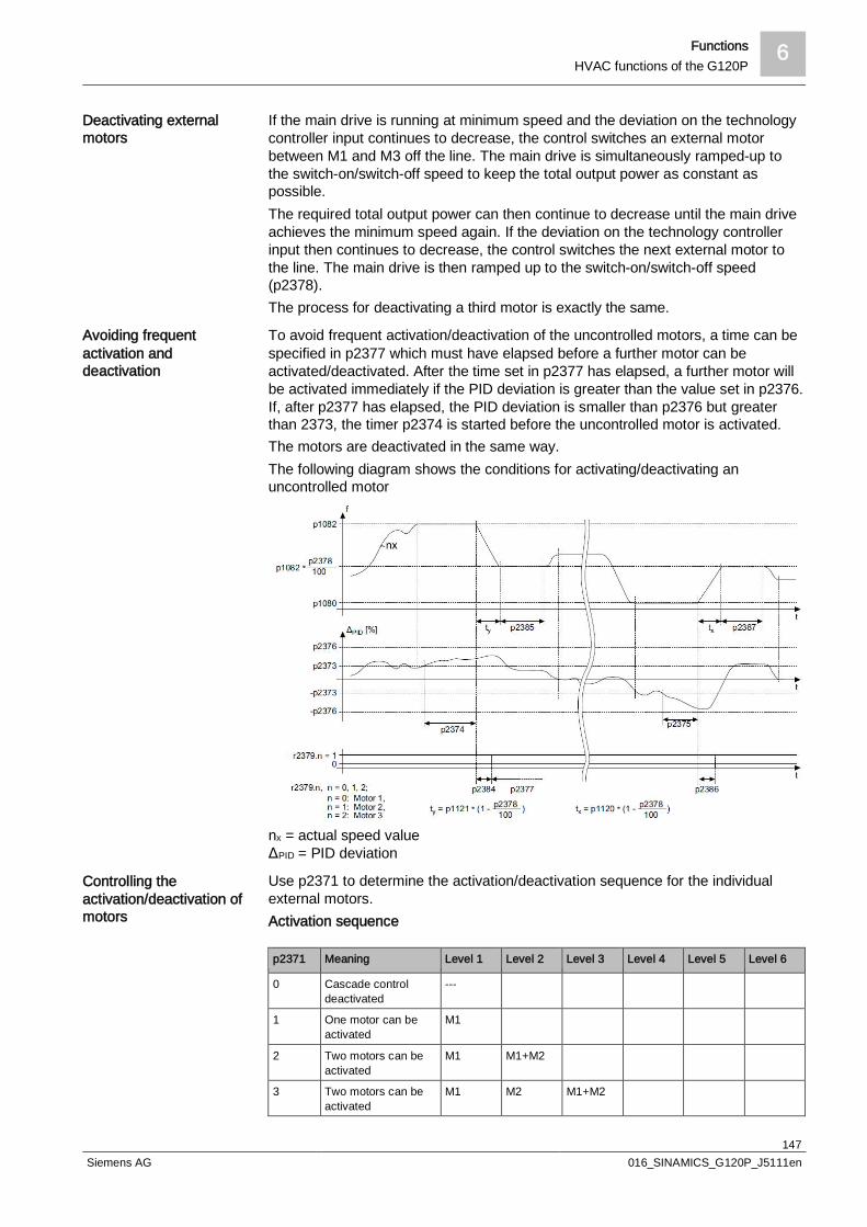
Functions 6HVAC functions of the G120P
147Siemens AG 016_SINAMICS_G120P_J5111en
If the main drive is running at minimum speed and the deviation on the technologycontroller input continues to decrease, the control switches an external motorbetween M1 and M3 off the line. The main drive is simultaneously ramped-up tothe switch-on/switch-off speed to keep the total output power as constant aspossible.The required total output power can then continue to decrease until the main driveachieves the minimum speed again. If the deviation on the technology controllerinput then continues to decrease, the control switches the next external motor tothe line. The main drive is then ramped up to the switch-on/switch-off speed(p2378).The process for deactivating a third motor is exactly the same.
To avoid frequent activation/deactivation of the uncontrolled motors, a time can bespecified in p2377 which must have elapsed before a further motor can beactivated/deactivated. After the time set in p2377 has elapsed, a further motor willbe activated immediately if the PID deviation is greater than the value set in p2376.If, after p2377 has elapsed, the PID deviation is smaller than p2376 but greaterthan 2373, the timer p2374 is started before the uncontrolled motor is activated.The motors are deactivated in the same way.The following diagram shows the conditions for activating/deactivating anuncontrolled motor
nx = actual speed valueΔPID = PID deviation
Use p2371 to determine the activation/deactivation sequence for the individualexternal motors.Activation sequence
p2371 Meaning Level 1 Level 2 Level 3 Level 4 Level 5 Level 6
0 Cascade controldeactivated
---
1 One motor can beactivated
M1
2 Two motors can beactivated
M1 M1+M2
3 Two motors can beactivated
M1 M2 M1+M2
Deactivating externalmotors
Avoiding frequentactivation anddeactivation
Controlling theactivation/deactivation ofmotors
6 FunctionsHVAC functions of the G120P
148Siemens AG 016_SINAMICS_G120P_J5111en
p2371 Meaning Level 1 Level 2 Level 3 Level 4 Level 5 Level 6
4 Three motors can beactivated
M1 M1+M2 M1+M2+M3
5 Three motors can beactivated
M1 M3 M1+M3 M1+M2+M3
6 Three motors can beactivated
M1 M2 M1+M2 M2+M3 M1+M2+M3
7 Three motors can beactivated
M1 M1+M2 M3 M1+M3 M1+M2+M3
8 Three motors can beactivated
M1 M2 M3 M1+M3 M2+M3 M1+M2+M3
Deactivation sequence
p2371 Activated motors Level 1 Level 2 Level 3 Level 4 Level 5 Level 6
1 M1 M1
2 M1+M2 M1+M2 M1
3 M1+M2 M1+M2 M2 M1
4 M1+M2+M3 M1+M2+M3
M1+M2 M1
5 M1+M2+M3 M1+M2+M3
M3+M1 M3 M1
6 M1+M2+M3 M1+M2+M3
M3+M2 M2+M1 M2 M1
7 M1+M2+M3 M1+M2+M3
M3+M1 M3 M2+M1 M1
8 M1+M2+M3 M1+M2+M3
M3+M2 M3+M1 M3 M2 M1
If you are using motors of the same power rating, you can use p2372 to definewhether the motors are to be activated/deactivated following the setting specified inp2371 (p2372 = 0) or based on the operating hours (p2372 = 1, 2 ,3. For details,see parameter list).
p0730 = r2379.0 Signal source for digital output 0Control external motor 1 via DO 0
p0731 = r2379.1 Signal source for digital output 1Control external motor 2 via DO 1
p0732 = r2379.2 Signal source for digital output 2Control external motor 3 via DO 2
p2200 = 1 Technology controller enableActivate technology controller
p2251 = 0 Technology controller modeTechnology controller as main speed setpoint
p2370 Cascade control – enableSignal source for staging on/off
p2371 Cascade control – configurationActivate staging and define activation sequence
p2372 Cascade control – motor selection modeDefine automatic motor activation
p2373 Cascade control – activation thresholdDefine activation threshold
p2374 Cascade control – activation delayDefine delay time
Setting and activating thecascade control
Functions 6HVAC functions of the G120P
149Siemens AG 016_SINAMICS_G120P_J5111en
p2375 Cascade control deactivation delayDefine delay time for destaging
p2376 Cascade control – overcontrol thresholdDefine overcontrol threshold
p2377 Cascade control – interlock timeDefine interlock time
p2378 Cascade control – switch-on/switch-off speedDefining the speed for the main drive after activating/deactivating a motor
r2379 Cascade control – status word
p2380 Cascade control – operating hours
p2381 Cascade control – maximum time for continuous operation
p2382 Cascade control – absolute operating time limit
p2383 Cascade control – deactivation sequenceDefine deactivation sequence for an OFF command
p2384 Cascade control – motor ON delayDefine motor ON delay
p2385 Cascade control – activation speed hold timeDefine speed hold time after activating an external motor
p2386 Cascade control – motor OFF delayDefine motor OFF delay
p2387 Cascade control – deactivation speed hold timeDefine speed hold time after deactivating an external motor
For more details about parameters, please refer to the List Manual.
6.3.6 Connecting several motorsSeveral motors can be connected in parallel at the G120P's output. All connectedmotors start and stop at the same time.Provided all connected motors have the same number of poles, they all turn at thesame speed.
The maximum required output current according to the following formula plays adecisive role in dimensioning the variable speed drive correctly.IVSD ≥ (IMotor 1 + IMotor 2 + ...+ IMotor n) • 1.1The factor 1.1 is for safety purposes in the event that one or more motors areoverloaded.When connecting several motors, the rated currents – not the rated powers – of theindividual motors must be added together to dimension the variable speed drivecorrectly.
Please note the following points when connecting several motors:l The sum of the lengths of all motor connection cables must not exceed the
permitted cable length.The permitted cable lengths for unfiltered devices can be found under Cablelengths [ 86] and those for devices with filters under Filter Overview [ 89].
l To protect the motors, use individual motor protection relays, PTC resistors, orcircuit breakers, as the p0610 protection function "Motor-overtemperatureresponse" does not function during multi-motor operation.
l Motor data identification must not take place during commissioning.l Where possible, avoid using contactors or service switches between variable
speed drives and the individual motors. Details can be found in Section Outputcontactors and motor protection relays [ 96].
6 FunctionsHVAC functions of the G120P
150Siemens AG 016_SINAMICS_G120P_J5111en
NOTICE
Several motors on one variable speed driveIn the case of several motors on one variable speed drive, sensorless vectorcontrol must not be used. Torque monitoring is not available either. The variablespeed drive can only apply the motor model to an individual motor. Use the V/f control mode in this case.
You will find additional information in the Section Control modes [ 109].
NOTICE
Flying restart with several motorsThe "flying restart" function only functions if all motors are running at the samespeed. Use a mechanical motor group coupling or avoid using the flying restart
function.
You will find additional information in the Section Flying restart [ 119].
6.3.7 Multi-zone controlMulti-zone control is used to control quantities such as pressure or temperature viathe technology setpoint deviation. The setpoints and actual values are fed in viathe analog inputs as current (0 to 20 mA) or voltage (0 to 10 V) or as a percentagevia temperature-dependent resistances (LG-Ni1000/Pt1000, 0 °C = 0%;100 °C = 100%).
There are three control variants for multi-zone control, which are selected viap31021:l One setpoint and 1, 2, or 3 actual values
The actual value for the control can be calculated as a mean value, a maximumvalue, or a minimum value. You can find all of the setting options in theparameter list in parameter p31022.– Mean value: The deviation from the setpoint of the mean value of two or
three actual values is controlled.– Minimum value: The deviation from the setpoint of the smallest actual value
is controlled.– Maximum value: The deviation from the setpoint of the highest actual value
is controlled.l Two pairs of setpoints/actual values as a maximum value control (cooling)
The maximum value control compares two pairs of setpoints/actual values andcontrols the actual value that has the largest deviation upwards from itsassociated setpoint. No control takes place when both actual values are belowtheir setpoints.In order to avoid frequent changeover, the variable speed drive only switchesover if the deviation of the controlled setpoint/actual value pair is more than twopercent lower than the deviation of the uncontrolled value pair.
l Two pairs of setpoints/actual values as a minimum value control (heating)The minimum value control compares two pairs of setpoints/actual values andcontrols the actual value that has the largest deviation downwards from itsassociated setpoint. No control takes place when both actual values are above
Control variants for multi-zone control
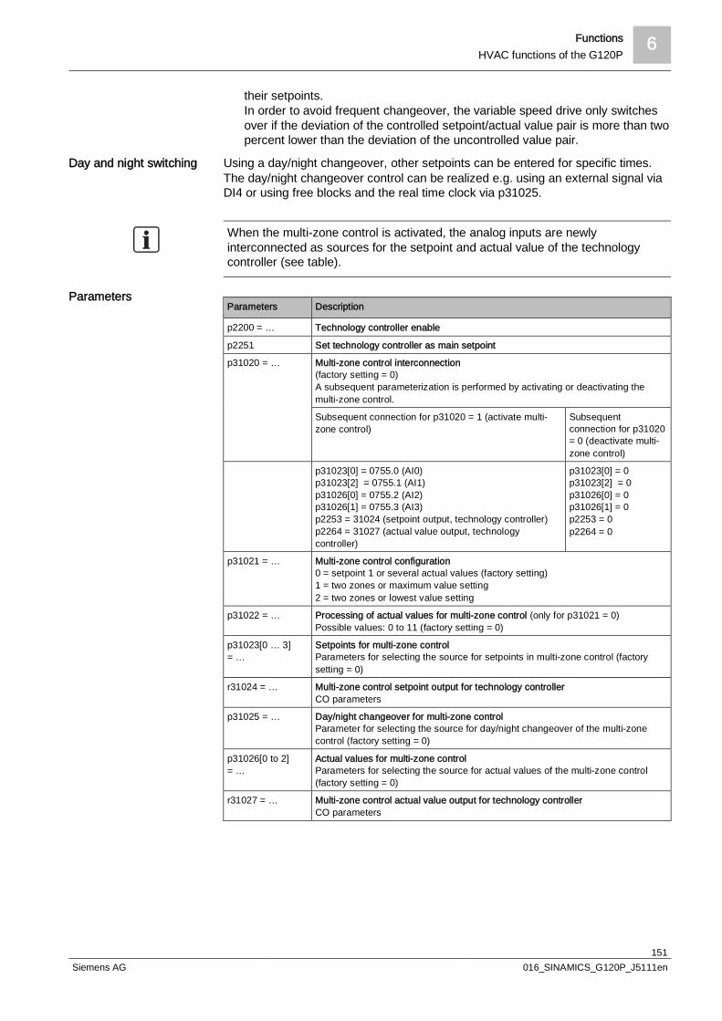
Functions 6HVAC functions of the G120P
151Siemens AG 016_SINAMICS_G120P_J5111en
their setpoints.In order to avoid frequent changeover, the variable speed drive only switchesover if the deviation of the controlled setpoint/actual value pair is more than twopercent lower than the deviation of the uncontrolled value pair.
Using a day/night changeover, other setpoints can be entered for specific times.The day/night changeover control can be realized e.g. using an external signal viaDI4 or using free blocks and the real time clock via p31025.
When the multi-zone control is activated, the analog inputs are newlyinterconnected as sources for the setpoint and actual value of the technologycontroller (see table).
Parameters Description
p2200 = … Technology controller enable
p2251 Set technology controller as main setpoint
p31020 = … Multi-zone control interconnection(factory setting = 0)A subsequent parameterization is performed by activating or deactivating themulti-zone control.
Subsequent connection for p31020 = 1 (activate multi-zone control)
Subsequentconnection for p31020= 0 (deactivate multi-zone control)
p31023[0] = 0755.0 (AI0)p31023[2] = 0755.1 (AI1)p31026[0] = 0755.2 (AI2)p31026[1] = 0755.3 (AI3)p2253 = 31024 (setpoint output, technology controller)p2264 = 31027 (actual value output, technologycontroller)
p31023[0] = 0p31023[2] = 0p31026[0] = 0p31026[1] = 0p2253 = 0p2264 = 0
p31021 = … Multi-zone control configuration0 = setpoint 1 or several actual values (factory setting)1 = two zones or maximum value setting2 = two zones or lowest value setting
p31022 = … Processing of actual values for multi-zone control (only for p31021 = 0)Possible values: 0 to 11 (factory setting = 0)
p31023[0 … 3]= …
Setpoints for multi-zone controlParameters for selecting the source for setpoints in multi-zone control (factorysetting = 0)
r31024 = … Multi-zone control setpoint output for technology controllerCO parameters
p31025 = … Day/night changeover for multi-zone controlParameter for selecting the source for day/night changeover of the multi-zonecontrol (factory setting = 0)
p31026[0 to 2]= …
Actual values for multi-zone controlParameters for selecting the source for actual values of the multi-zone control(factory setting = 0)
r31027 = … Multi-zone control actual value output for technology controllerCO parameters
Day and night switching
Parameters

6 FunctionsHVAC functions of the G120P
152Siemens AG 016_SINAMICS_G120P_J5111en
Please note that when multi-zone control is activated, any BICO interconnectionspresent for analog inputs and for the technology controller's setpoint and actualvalue are cancelled and interconnected with the links defined in the factory.When you deactivate multi-zone control, the associated BICO interconnectionsare cancelled.
The temperature in a large office is measured at three points and transferred to thevariable speed drive using analog inputs. LG-Ni1000 temperature sensors are usedas actual value sensors. The setpoint temperature is specified via the analog input0 and can be set in the range from 8 °C to 30 °C by a controller. Overnight, theaverage temperature should be 16 °C.
Parameter settings
Parameters Description
p2200.0 = 1 Technology controller enable
p2251 = 0 Set technology controller as main setpoint
p2900.0 = 16 Temperature setpoint overnight as a fixed percentage value
p31020 = 1 Activate multi-zone control
p31021 = 0 Select multi-zone control with one setpoint and three actual values
p31022 = 7 Three actual values, one setpoint. The average value of the three actual values isused for the control.
p31023.0 = 755.0 Temperature setpoint via analog input 0
p0756.0 = 0 Select analog input type (voltage input 0 to 10 V)
p0757.0 = 0 /p0758.0 = 8
Set the lower value to 8 °C (0 V ≙ 8 °C)
p0759.0 = 10 /p0760.0 = 30
Set the upper value to 30 °C (10 V ≙ 30 °C)
p31023.1 =2900.0
Supply p31023.1 with the value written in p2900 to reduce the temperatureovernight
p31026.0 = 755.2 Temperature actual value 1 via analog input 2 as a percentage value
p0756.2 = 6 Select analog input type (temperature sensor LG-Ni1000)
p0757.2 = 0 /p0758.2 = 0
Set lower value of the scaling characteristic
p0759.2 = 100 /p0760.2 = 100
Set upper value of the scaling characteristic
p31026.1 = 755.3 Temperature actual value 2 via analog input 3 as a percentage value
p0756.3 = 6 Select analog input type (temperature sensor LG-Ni1000)
p0757.3 = 0 /p0758.3 = 0
Set lower value of the scaling characteristic
p0759.3 = 100 /p0760.3 = 100
Set upper value of the scaling characteristic
p31026.2 = 755.1 Temperature actual value 3 via temperature sensor with current output(0 mA to 20 mA) via analog input 1
p0756.1 = 2 Select analog input type (current input 0 to 20 mA)
p0757.1 = 0 /p0758.1 = 0
Set lower value of the scaling characteristic (0 mA ≙ 0 °C)
p0759.1 = 20 /p0760.1 = 100
Set upper value of the scaling characteristic (20 mA ≙ 100%)
p31025 = 722.4 Changeover from day to night via digital input 4
Example
Functions 6HVAC functions of the G120P
153Siemens AG 016_SINAMICS_G120P_J5111en
You will find more information about this multi-zone control in the parameter listand in function diagram 7972 of the List Manual.
6.3.8 Energy-saving mode (hibernation mode)The energy-saving mode is mainly used for pumps and fans. Typical applicationsinclude pressure and temperature controls.In the energy-saving mode, the variable speed drive stops and starts the motordepending on the system conditions. The energy-saving mode can be activated viathe technology controller (without external commands via terminals or businterface) and via an external setpoint input.The energy-saving mode offers the advantages of energy saving, loweringmechanical wear, and reduced noise.
In the energy-saving mode, if the setpoint is to be entered from the motorizedpotentiometer or from the motorized potentiometer of the technology controller,you must set p1030.4 or p2230.4 = 1.
After the variable speed drive has been powered up, the motor goes into theenergy-saving mode if the energy-saving mode start speed has still not beenreached after the highest value from p1120 (ramp-up time), p2391 (energy-savingmode delay time) and 20 s have expired.
The energy-saving mode starts as soon as the motor speed drops below theenergy-saving mode start speed. However, the motor is only switched off after anadjustable time has expired. If, during this time, the speed setpoint increasesabove the energy-saving mode start speed due to pressure or temperaturechanges, the energy-saving mode is exited and the variable speed drive goes intonormal operation.In the energy-saving mode, the motor is shut down; however, the speed setpointand/or the technology controller deviation are/is monitored.l For an external setpoint input (without technology controller) the speed setpoint
is monitored and the motor is switched-on again as soon as the setpointincreases above the restart speed. The restart speed is calculated as follows:Restart speed = p1080 + p2390 + p2393.The positive speed setpoint is monitored in the factory settings, meaning thatthe motor is switched on as soon as the setpoint exceeds the restart speed.If the negative speed setpoint is also to be monitored, the setpoint amountmust be monitored. This can be set with p1110 = 0.Additional setting options are described in the parameter list, in functiondiagrams 3030 and 3040, as well as in the associated parameter descriptions.
l For a setpoint input via the technology controller, the technology controllerdeviation (r2273) is monitored and the motor is switched back on when thisdeviation is larger than the energy-saving mode restart value (p2392).Only the positive technology controller deviation is monitored in the factorysettings, meaning that the motor is switched on as soon as this deviation islarger than the energy-saving mode restart value (p2392).If the motor is to be switched back on even in the event of negative technologycontroller deviation, the amount of this deviation must be monitored.For this, p2298 = 2292 must be set. The percentage value for the minimumlimit can be entered in p2292.Additional setting options are provided in the parameter list in function diagram7958 and in the associated parameter descriptions.
Operating principle

6 FunctionsHVAC functions of the G120P
154Siemens AG 016_SINAMICS_G120P_J5111en
In order to prevent frequent starts and stops, the speed may be boosted for a shorttime before shutdown (boost). This function can be disabled by setting the boosttime (p2394) to 0.After an adjustable time (p2396) has expired, the energy-saving mode can beended and switched to normal mode, particularly to avoid tank deposits in the caseof liquids.The parameter settings required for the respective variant can be found in thefollowing tables.
In this operating mode, the technology controller must be activated as the setpointsource (p2200) and used as the main setpoint (p2251). The function can beoperated both with and without boost.
The setpoint is provided via an external source (e.g. a temperature sensor) in thisoperating mode. The technology setpoint can be used as a supplementary setpointfor this.
Energy-saving mode using an external setpoint with boost
Energy-saving mode using an external setpoint without boost
Boost functions
Energy-saving mode withsetpoint input using theinternal technologycontroller
Energy-saving mode withexternal setpoint input

Functions 6HVAC functions of the G120P
155Siemens AG 016_SINAMICS_G120P_J5111en
Parameters Description Via tech.setpoint
Via ext.setpoint
p1080 = … Minimum speed x x
0 (factory setting) … 19,500 rpm. Lower limit of the motorspeed is dependent on the speed setpoint.
p1110 = … Block negative directionParameter to block the negative direction
- x
p2200 = … Enable technology controller x -
0 Technology controller deactivated (factory setting)
1 Technology controller activated
p2251 = 1 Technology controller mode x -
0 Technology controller as main setpoint (factory setting)
1 Technology controller as supplementary setpoint
p2298 = … Technology controller minimum limitingParameter for the minimum limiting of the technologycontroller
x -
p2398 = … Energy-saving operating mode x x
0 Energy-saving mode disabled (factory setting)
1 Energy-saving mode enabled
p2390 = … Energy-saving mode start speed0 (factory setting) … 21,000 rpm. As soon as this speed isundershot, the energy-saving mode delay time starts andswitches off the motor once it expires. The energy-savingmode start speed is calculated as follows:Start speed = p1080 + p2390p1080 = minimum speedp2390 = energy-saving mode start speed.
x x
p2391 = … Energy-saving mode delay time0 to 3,599 s (factory setting 120). The energy-saving modedelay time starts as soon as the output frequency of thevariable speed drive drops below the energy-saving modestart speed p2390. If the output frequency increases abovethis threshold during the delay time, the energy-saving modedelay time is interrupted. Otherwise, the motor is switchedoff after the delay time has expired (if necessary, after ashort boost).
x x
p2392 = … Energy-saving mode restart value (in %)Required if the technology controller is used as the mainsetpoint.As soon as the technology controller deviation (r2273)exceeds the energy-saving mode restart value, the variable
x -
Adjustable parameters

6 FunctionsHVAC functions of the G120P
156Siemens AG 016_SINAMICS_G120P_J5111en
Parameters Description Via tech.setpoint
Via ext.setpoint
speed drive switches to normal operation and the motorstarts with a setpoint of 1.05 * (p1080 + p2390). As soon asthis value is reached, the motor continues to operate withthe setpoint of the technology controller (r2260).
p2393 = … Energy-saving mode restart speed (rpm)Required for external setpoint setting. The motor starts assoon as the setpoint exceeds the restart speed. The restartspeed is calculated as follows:Restart speed = p1080 + p2390 + p2393p1080 = minimum speedp2390 = energy-saving mode start speedp2393 = energy-saving mode restart speed
- x
p2394 = … Energy-saving mode boost duration0 (factory setting) to 3,599 s. Before the variable speed driveswitches over into the energy-saving mode, the motor isaccelerated for the time set in p2394 according to theacceleration ramp, but not to more than the speed set inp2395.
x x
p2395 = … Energy-saving mode boost speed0 (factory setting) to 21,000 rpm. Before the variable speeddrive switches over into the energy-saving mode, the motoris accelerated for the time set in p2394 according to theacceleration ramp, but not to more than the speed set inp2395.Caution:Make sure that the boost cannot cause any overpressure oroverflow conditions.
x x
p2396 = … Maximum energy-saving mode shutdown time0 (factory setting) to 863,999 s. At the latest when this timeexpires, the variable speed drive switches to normaloperation and is accelerated up to the start speed (p1080 +p2390). If the variable speed drive switches to normaloperation before this, the shutdown time is reset to the valueset in this parameter.The automatic switch over to normal operation isdeactivated after a specific time via p2396 = 0.
x x
Parameters Description
r2273 Display of the setpoint/actual value deviation of the technology controller
r2397 Actual energy-saving mode output speedActual boost speed before the pulses are inhibited or the actual start speed after restart.
r2399 Energy-saving mode status word
00 Energy-saving mode enabled (p2398 <>0)
01 Energy saving mode active
02 Energy-saving mode delay time active
03 Energy-saving mode boost active
04 Energy-saving mode motor switched off
05 Energy-saving mode motor switched off, cyclical restart active
06 Energy-saving mode motor starts back up.
07 Energy-saving mode supplies ramp-function generator's total setpoint
08 Energy-saving mode bypasses the ramp-function generator in the setpoint channel
6.3.9 Bypass (bypassing the variable speed drive)The integrated bypass function is used in the following cases:
Monitoring parameters

Functions 6HVAC functions of the G120P
157Siemens AG 016_SINAMICS_G120P_J5111en
l If an application is intended to run for a longer period of time with maximummotor power
l If an application requires a variable speed drive bypass system for safetyreasons
The bypass function uses a digital output to control the bypass and variable speeddrive relays. If both digital outputs are already being used for other functions, it ispossible to use an external bypass.
In the bypass function, the motor is either operated by the variable speed drive ordirectly on the line.The bypass is controlled as follows:l Depending on the speed via the variable speed drivel Independently of the speedl Via a signal from the variable speed drivel Via a higher-level controlIf the bypass is controlled by a higher-level control, the control must lock thecontactors so they cannot switch on at the same time.If controlled by the variable speed drive, the digital outputs are used to activate twocontactors via which the motor is powered. The variable speed drive is providedwith contactor position feedback via the digital inputs. This is evaluated. If usingdirect connection logic (high level = ON), both contactors should be NO contacts.
A = Motor starter (mechanical interlocking) ----- Control via digital output- - - - Feedback via digital inputK1 contactor for variable speed driveoperationK2 contactor for bypass operation
At changeover to line operation, contactor K1 is opened (after the variable speeddrive pulses have been inhibited). The system then waits for the motor de-excitation time to elapse, after which contactor K2 is closed, connecting the motordirectly to the line supply.When the motor is switched to the line supply, an equalizing current flows that mustbe taken into account when the protective equipment is selected and dimensioned.When changing over to variable speed drive operation, initially contactor K2 mustbe opened and after the de-excitation time, contactor K1 is closed. The variable
Bypass circuit for controlusing the variable speeddrive
Changeover operationbetween line andvariable speed driveoperation
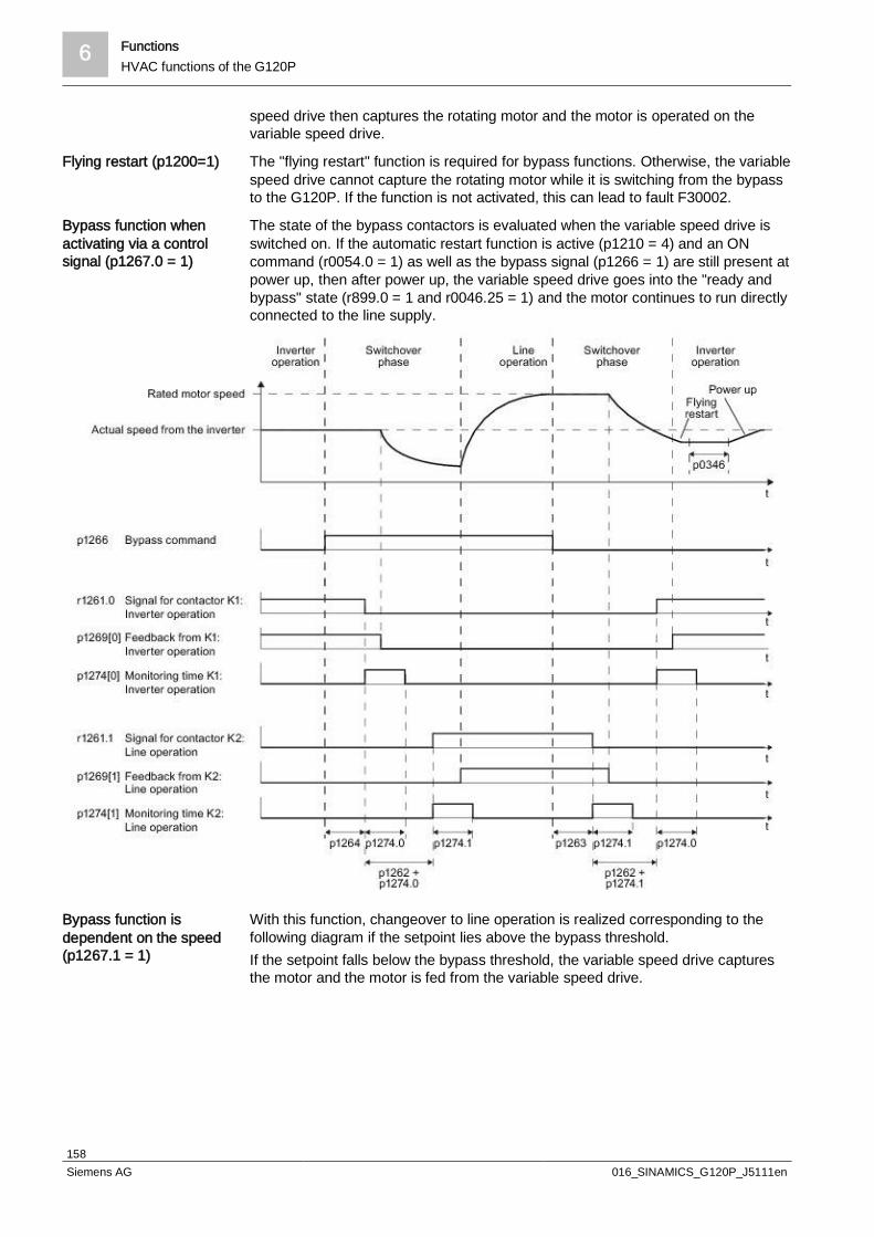
6 FunctionsHVAC functions of the G120P
158Siemens AG 016_SINAMICS_G120P_J5111en
speed drive then captures the rotating motor and the motor is operated on thevariable speed drive.
The "flying restart" function is required for bypass functions. Otherwise, the variablespeed drive cannot capture the rotating motor while it is switching from the bypassto the G120P. If the function is not activated, this can lead to fault F30002.
The state of the bypass contactors is evaluated when the variable speed drive isswitched on. If the automatic restart function is active (p1210 = 4) and an ONcommand (r0054.0 = 1) as well as the bypass signal (p1266 = 1) are still present atpower up, then after power up, the variable speed drive goes into the "ready andbypass" state (r899.0 = 1 and r0046.25 = 1) and the motor continues to run directlyconnected to the line supply.
With this function, changeover to line operation is realized corresponding to thefollowing diagram if the setpoint lies above the bypass threshold.If the setpoint falls below the bypass threshold, the variable speed drive capturesthe motor and the motor is fed from the variable speed drive.
Flying restart (p1200=1)
Bypass function whenactivating via a controlsignal (p1267.0 = 1)
Bypass function isdependent on the speed(p1267.1 = 1)
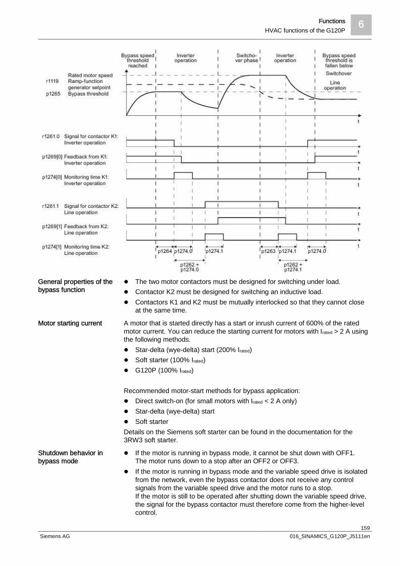
Functions 6HVAC functions of the G120P
159Siemens AG 016_SINAMICS_G120P_J5111en
l The two motor contactors must be designed for switching under load.l Contactor K2 must be designed for switching an inductive load.l Contactors K1 and K2 must be mutually interlocked so that they cannot close
at the same time.
A motor that is started directly has a start or inrush current of 600% of the ratedmotor current. You can reduce the starting current for motors with Irated > 2 A usingthe following methods.l Star-delta (wye-delta) start (200% Irated)l Soft starter (100% Irated)l G120P (100% Irated)
Recommended motor-start methods for bypass application:l Direct switch-on (for small motors with Irated < 2 A only)l Star-delta (wye-delta) startl Soft starterDetails on the Siemens soft starter can be found in the documentation for the3RW3 soft starter.
l If the motor is running in bypass mode, it cannot be shut down with OFF1.The motor runs down to a stop after an OFF2 or OFF3.
l If the motor is running in bypass mode and the variable speed drive is isolatedfrom the network, even the bypass contactor does not receive any controlsignals from the variable speed drive and the motor runs to a stop.If the motor is still to be operated after shutting down the variable speed drive,the signal for the bypass contactor must therefore come from the higher-levelcontrol.
General properties of thebypass function
Motor starting current
Shutdown behavior inbypass mode

6 FunctionsHVAC functions of the G120P
160Siemens AG 016_SINAMICS_G120P_J5111en
l If the motor is running in bypass mode, while the variable speed drive is in the"ready and bypass" state (r899.0 = 1 and r0046.25 = 1), then the motortemperature monitoring via the temperature sensor is active.
l If the motor is running in bypass mode, while the variable speed drive is in the"ready and bypass" state (r899.0 = 1 and r0046.25 = 1), then the overloadprotection for the motor must be realized on the plant or system side.
In high-availability systems or if the ESM function is required, we recommend anexternal bypass solution with an additional network bypass fuse. The externalbypass with supplementary mains fuse provides the system redundancy that isrequired in such applications.See schematic diagram: "External bypass with direct switch-on, troubleshooting –example with supplementary fuse".
Parameters Description
p1260 Bypass configurationActivating the bypass function
r1261 Bypass control/status wordControl and feedback signals for the bypass function.
p1262 Bypass dead timeChangeover time for contactors. This should be longer than the motor's demagnetizingtime.
p1263 Debypass delay timeDelay time for switching back to variable speed drive operation.
p1264 Bypass delay timeDelay time for switching to bypass mode.
p1265 Bypass speed thresholdSpeed threshold for switching to bypass mode.
p1266 Bypass control commandSignal source for switching to bypass mode.
p1267 Bypass changeover source configurationSwitch to bypass mode using speed threshold or control signal.
p1269 Bypass switch feedback signalSignal source for contactor feedback for bypass mode.
p1274 Bypass switch monitoring timeMonitoring time setting for bypass contactors.
For more details about parameters, please refer to the List Manual.
Depending on the bypass setting (p1260), even disconnections can activate thebypass. If the automatic restart is not activated, the motor is driven by the bypassuntil the site maintenance technician manually resets and restarts the G120P.You can, however, automatically acknowledge the disconnection and restart theG120P with the automatic restart. In this case, the drive automatically resets thedisconnection (depending on the settings for the automatic reset) and switchesback from the bypass to the drive.
There may also be an additional advantage for sites where temporary problemscan arise, for example voltage peaks at the G120P inputs lead to shutdown due toovervoltage.Example:You do not want to monitor every fault message caused by a temporary problem,particularly if the G120P cannot reset and restart itself.If the "automatic restart" function is activated in connection with an external bypass(p1210=4 or 6), every power system fault is acknowledged by the G120P within therestart time delay (p1212) and restart time increase (p1213). If there was only a
Temperature monitoringand overload protectionin bypass mode
High-availability,Essential Service Mode(ESM), and bypass
Parameters for settingthe bypass function
Automatic restart afterfailure
Automatic reset and timedelay for fault signals
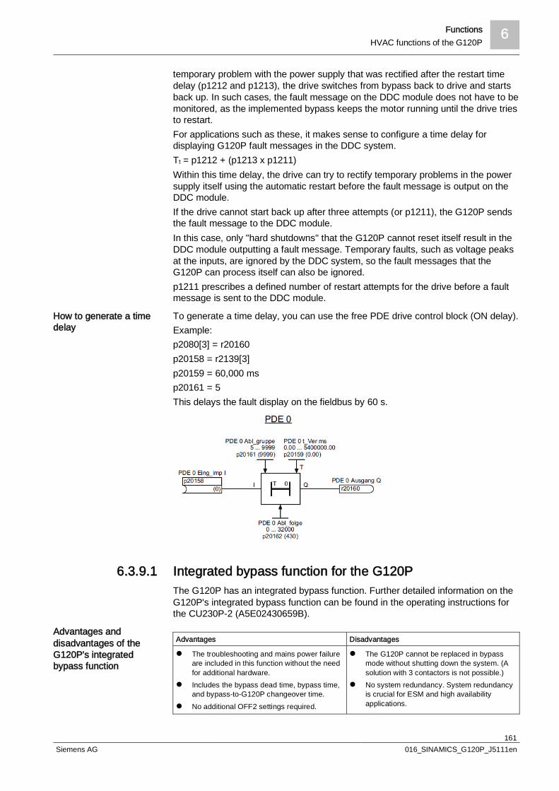
Functions 6HVAC functions of the G120P
161Siemens AG 016_SINAMICS_G120P_J5111en
temporary problem with the power supply that was rectified after the restart timedelay (p1212 and p1213), the drive switches from bypass back to drive and startsback up. In such cases, the fault message on the DDC module does not have to bemonitored, as the implemented bypass keeps the motor running until the drive triesto restart.For applications such as these, it makes sense to configure a time delay fordisplaying G120P fault messages in the DDC system.Tt = p1212 + (p1213 x p1211)Within this time delay, the drive can try to rectify temporary problems in the powersupply itself using the automatic restart before the fault message is output on theDDC module.If the drive cannot start back up after three attempts (or p1211), the G120P sendsthe fault message to the DDC module.In this case, only "hard shutdowns" that the G120P cannot reset itself result in theDDC module outputting a fault message. Temporary faults, such as voltage peaksat the inputs, are ignored by the DDC system, so the fault messages that theG120P can process itself can also be ignored.p1211 prescribes a defined number of restart attempts for the drive before a faultmessage is sent to the DDC module.
To generate a time delay, you can use the free PDE drive control block (ON delay).Example:p2080[3] = r20160p20158 = r2139[3]p20159 = 60,000 msp20161 = 5This delays the fault display on the fieldbus by 60 s.
6.3.9.1 Integrated bypass function for the G120PThe G120P has an integrated bypass function. Further detailed information on theG120P's integrated bypass function can be found in the operating instructions forthe CU230P-2 (A5E02430659B).
Advantages Disadvantages
l The troubleshooting and mains power failureare included in this function without the needfor additional hardware.
l Includes the bypass dead time, bypass time,and bypass-to-G120P changeover time.
l No additional OFF2 settings required.
l The G120P cannot be replaced in bypassmode without shutting down the system. (Asolution with 3 contactors is not possible.)
l No system redundancy. System redundancyis crucial for ESM and high availabilityapplications.
How to generate a timedelay
Advantages anddisadvantages of theG120P's integratedbypass function

6 FunctionsHVAC functions of the G120P
162Siemens AG 016_SINAMICS_G120P_J5111en
l No additional time delay relay required.
Bypass command to DO0.
P No. Value Description
P0730 1261.0 DO0 VSD output relay
P0731 1261.1 DO1 power supply relay
p1260 3 Bypass activated
p1262 s Bypass dead time (should be > p0347)
p1263 s De-bypass time
p1264 s Bypass time
p1266 r0722.5 Bypass control command: DI5
p1267 01 Bypass via signal
p1200 1 Flying restart
p1210 26 Automatic restart
p1212 s Time until the first restart
p1213 s Restart time increase
The three following circuit diagrams display the possible configurations for theG120P's integrated bypass function. The difference between the threeconfigurations is the method of starting the motor. The first example uses directswitch-on, the second circuit diagram displays a star-delta (wye-delta) start, andthe final example uses a soft starter.
Parameter settings forthe G120P integratedbypass function
Setting up the bypassfunction for the G120P

Functions 6HVAC functions of the G120P
163Siemens AG 016_SINAMICS_G120P_J5111en
Internal bypass function with direct switch-on
Legend
K1 VSD contactor S1 EMERGENCY STOP
K2 Bypass contactor S2 G120P ON/OFF command
F1 Fuse (power supply) S3 Bypass command
F4 Fuse (control circuit)
F4N F4 Neutral isolator
F5 Thermal relay

6 FunctionsHVAC functions of the G120P
164Siemens AG 016_SINAMICS_G120P_J5111en
Internal bypass function, direct star-delta (wye-delta)
Legend
K1 ON delay contactor (star-delta (wye-delta) start) F1 Fuse (power supply)
K2 Star (wye) contactor F4 Fuse (control circuit)
K3 Bypass contactor F4N F4 Neutral isolator
K4 Delta contactor F5 Thermal relay
K5 VSD contactor S1 EMERGENCY STOP
S2 G120P ON/OFF command
S3 Bypass command

Functions 6HVAC functions of the G120P
165Siemens AG 016_SINAMICS_G120P_J5111en
Internal bypass function, direct soft starter
Legend
K1 Bypass contactor S1 EMERGENCY STOP
K2 VSD contactor S2 G120P ON/OFF command
F1 Fuse (power supply) S3 Bypass command
F4 Fuse (control circuit) A1 Siemens Sirius soft starter
F4N F4 Neutral isolator
F5 Thermal relay

6 FunctionsHVAC functions of the G120P
166Siemens AG 016_SINAMICS_G120P_J5111en
6.3.9.2 External bypass functionDepending on the application requirements, additional settings and componentsare required for the external bypass solution in order to establish compatibility withthe G120P's internal bypass function.For high-availability applications, you can only achieve the required systemredundancy via the external bypass. The logic for the external bypass can even beimplemented in the DDC system.
The G120P is normally switched off using an OFF1 command. Stopping with OFF1means that the variable speed drive stops the motor with the programmed ramp-down time. In the case of an external bypass, however, the bypass signal starts theramp-down time and immediately opens the output contactor to the G120P.Opening the contactor to the motor while current is flowing can cause irreparabledamage to the G120P's power circuit.A practical solution to this problem is to stop the variable speed drive using the"Operation deactivated" command instead of an OFF1 command (ramp-down)."Operation deactivated" means that the G120P Power Module and its outputs areimmediately separated. The motor runs down to a standstill without ramp-downtime.Set the following parameters to DI0 for this command:
P No. Index Value Description
P0840 0 722.0 BICO connection from DI0 and ON command
P0852 0 722.0 BICO connection from DI0 and "Operation activated" command
In common VSD applications, the VSD ON signal not only starts the drive, but alsocloses the contactor at the VSD output. This leads to disconnections, as thebouncing contactor changes the VSD output resistance.To ensure a soft and appropriate start, the VSD output contactor must be closedbefore the ON command is output at the DIThe contactor must not switch or bounce when the ON signal is applied.Avoid this problem by establishing a time delay for the ON command using thedelay contactor. The VSD contactor should first be closed, then the G120P shouldstart with a short time delay of 3 to 5 seconds via DI.Applications with a contactor at the VSD output (solution with 3 contactors) do notrequire a time delay for the ON signal. If the contactor at the input and output isclosed, the G120P requires a few seconds to power up and get ready foroperation. Once powered up, the G120P is ready. The input and output contactorsare closed properly and no shutdown takes place.
Two questions should be asked as part of the troubleshooting process:l What happens if the G120P shuts down?l What happens if the G120P's external power supply or internal DC power
supply fail?In a standard configuration with an external bypass, the G120P is shut down,although the bypass is not activated. This means that a special configuration isrequired to cover these fault states.Using one of the G120P's digital outputs, you can set up an application thatactivates the bypass in the following ways:l External signal (DI)l G120P fault or shutdownl Power supply failure or internal DC power supply for the G120P
"Operation deactivated"command for avoidingdisconnections
Time delay for ONcommand
Troubleshooting

Functions 6HVAC functions of the G120P
167Siemens AG 016_SINAMICS_G120P_J5111en
This means that all fault states are covered and the G120P application reaches ahigh level of reliability.
With an additional contactor at the G120P input, the VSD is completely isolatedfrom the power supply in bypass mode and can be replaced with ease. This canprovide significant added value for applications that require a high level ofreliability.
Advantages Disadvantages
l Three free digital outputs for other functions ifno troubleshooting is required
l System redundancy: crucial for ESM andhigh availability applications
l No bypass and de-bypass time or bypassdead time
l The troubleshooting only covers one digitaloutput. Only two digital outputs remain forother functions
l ON-command time delay required forconfiguration without a contactor at theG120P input.
The following diagrams provide a practical overview of the common externalbypass applications. Based on the three motor start configurations (direct switch-on, star-delta (wye-delta), soft starter), options are available with:l Contactorsl Troubleshootingl Contactor and troubleshooting
Three contactors
Advantages anddisadvantages of theexternal bypass
Setting up the externalbypass

6 FunctionsHVAC functions of the G120P
168Siemens AG 016_SINAMICS_G120P_J5111en
External bypass with direct switch-on
Legend
K1 Bypass contactor F4N F4 Neutral isolator
K2 VSD contactor F5 Thermal relay
K3 ON delay contactor (VSD ON/OFF command) S1 EMERGENCY STOP
F1 Fuse (power supply) S2 Switch (bypass/VSD/OFF)
F4 Fuse (control circuit) BMS Building management station (ON/OFF command)
Function parameter settings
p0840[0] = 722.0 (BICO connection from ON command toDI0)
p1210 = 26 (automatic restart)
p0852[0] = 722.0 (BICO connection from "Activate operation"command to DI0)
p1200 = 1 (flying restart)

Functions 6HVAC functions of the G120P
169Siemens AG 016_SINAMICS_G120P_J5111en
External bypass with direct switch-on, 3 contactors
Legend
K1 Bypass contactor F4N F4 Neutral isolator
K2 VSD input contactor F5 Thermal relay
K3 VSD output contactor S1 EMERGENCY STOP
F1 Fuse (power supply) S2 Switch (bypass/VSD/OFF)
F4 Fuse (control circuit) BMS Building management station (ON/OFF command)
Function parameter settings
p0840[0] = 722.0 (BICO connection from ON command toDI0)
p1210 = 26 (automatic restart)
p0852[0] = 722.0 (BICO connection from "Activate operation"command to DI0)
p1200 = 1 (flying restart)

6 FunctionsHVAC functions of the G120P
170Siemens AG 016_SINAMICS_G120P_J5111en
External bypass with direct switch-on, troubleshooting
Legend
K1 VSD contactor F4N F4 Neutral isolator
K2 ON delay contactor (VSD ON/OFF command) F5 Thermal relay
K3 Bypass contactor S1 EMERGENCY STOP
F1 Fuse (power supply) S2 Switch (bypass/VSD/OFF)
F4 Fuse (control circuit) BMS Building management station (ON/OFF command)
Function parameter settings
p0840[0] = 722.0 (BICO connection from ON command toDI0)
p1210 = 26 (automatic restart)
p0852[0] = 722.0 (BICO connection from "Activate operation"command to DI0)
p1200 = 1 (flying restart)
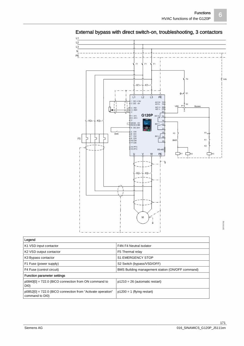
Functions 6HVAC functions of the G120P
171Siemens AG 016_SINAMICS_G120P_J5111en
External bypass with direct switch-on, troubleshooting, 3 contactors
Legend
K1 VSD input contactor F4N F4 Neutral isolator
K2 VSD output contactor F5 Thermal relay
K3 Bypass contactor S1 EMERGENCY STOP
F1 Fuse (power supply) S2 Switch (bypass/VSD/OFF)
F4 Fuse (control circuit) BMS Building management station (ON/OFF command)
Function parameter settings
p0840[0] = 722.0 (BICO connection from ON command toDI0)
p1210 = 26 (automatic restart)
p0852[0] = 722.0 (BICO connection from "Activate operation"command to DI0)
p1200 = 1 (flying restart)

6 FunctionsHVAC functions of the G120P
172Siemens AG 016_SINAMICS_G120P_J5111en
External bypass with direct switch-on, troubleshooting – examplewith supplementary fuse
Legend
K1 VSD contactor F4 Fuse (control circuit)
K2 ON delay contactor (VSD ON/OFF command) F4N F4 Neutral isolator
K3 Bypass contactor F5 Thermal relay
F1 Fuse (power supply) S1 EMERGENCY STOP
F2 Fuse (network bypass current) S2 Switch (bypass/VSD/OFF)
BMS Building management station (ON/OFF command)
Function parameter settings
p0840[0] = 722.0 (BICO connection from ON command toDI0)
p1210 = 26 (automatic restart)
p0852[0] = 722.0 (BICO connection from "Activate operation"command to DI0)
p1200 = 1 (flying restart)

Functions 6HVAC functions of the G120P
173Siemens AG 016_SINAMICS_G120P_J5111en
External bypass with star-delta (wye-delta) start
Legend
K1 ON delay contactor (star-delta (wye-delta) start) F1 Fuse (power supply)
K2 Star (wye) contactor F4 Fuse (control circuit)
K3 Bypass contactor F4N F4 Neutral isolator
K4 Delta contactor F5 Thermal relay
K5 VSD output contactor S1 EMERGENCY STOP
K6 ON delay contactor (VSD ON/OFF command) S2 Switch (bypass/VSD/OFF)
BMS Building management station (ON/OFF command)
Function parameter settings
p0840[0] = 722.0 (BICO connection from ON command toDI0)
p1210 = 26 (automatic restart)
p0852[0] = 722.0 (BICO connection from "Activate operation"command to DI0)
p1200 = 1 (flying restart)

6 FunctionsHVAC functions of the G120P
174Siemens AG 016_SINAMICS_G120P_J5111en
External bypass with star-delta (wye-delta), 3 contactors
Legend
K1 ON delay contactor (star-delta (wye-delta) start) F1 Fuse (power supply)
K2 Star (wye) contactor F4 Fuse (control circuit)
K3 Bypass contactor F4N F4 Neutral isolator
K4 Delta contactor F5 Thermal relay
K5 VSD output contactor S1 EMERGENCY STOP
K6 VSD input contactor S2 Switch (bypass/VSD/OFF)
BMS Building management station (ON/OFF command)
Function parameter settings
p0840[0] = 722.0 (BICO connection from ON command toDI0)
p1210 = 26 (automatic restart)
p0852[0] = 722.0 (BICO connection from "Activate operation"command to DI0)
p1200 = 1 (flying restart)

Functions 6HVAC functions of the G120P
175Siemens AG 016_SINAMICS_G120P_J5111en
External bypass with star-delta (wye-delta) start, troubleshooting
Legend
K1 ON delay contactor (star-delta (wye-delta) start) F1 Fuse (power supply)
K2 Star (wye) contactor F4 Fuse (control circuit)
K3 Bypass contactor F4N F4 Neutral isolator
K4 Delta contactor F5 Thermal relay
K5 VSD output contactor S1 EMERGENCY STOP
K6 ON delay contactor (VSD ON/OFF command) S2 Switch (bypass/VSD/OFF)
BMS Building management station (ON/OFF command)
Function parameter settings
p0840[0] = 722.0 (BICO connection from ON command toDI0)
p1210 = 26 (automatic restart)
p0852[0] = 722.0 (BICO connection from "Activate operation"command to DI0)
p1200 = 1 (flying restart)

6 FunctionsHVAC functions of the G120P
176Siemens AG 016_SINAMICS_G120P_J5111en
External bypass with star-delta (wye-delta), troubleshooting, 3contactors
Legend
K1 ON delay contactor (star-delta (wye-delta) start) F1 Fuse (power supply)
K2 Star (wye) contactor F4 Fuse (control circuit)
K3 Bypass contactor F4N F4 Neutral isolator
K4 Delta contactor F5 Thermal relay
K5 VSD output contactor S1 EMERGENCY STOP
K6 VSD input contactor S2 Switch (bypass/VSD/OFF)
BMS Building management station (ON/OFF command)
Function parameter settings
p0840[0] = 722.0 (BICO connection from ON command toDI0)
p1210 = 26 (automatic restart)
p0852[0] = 722.0 (BICO connection from "Activate operation" p1200 = 1 (flying restart)

Functions 6HVAC functions of the G120P
177Siemens AG 016_SINAMICS_G120P_J5111en
command to DI0)
External bypass with soft start
Legend
K1 Bypass contactor F5 Thermal relay
K2 VSD contactor S1 EMERGENCY STOP
F1 Fuse (power supply) S2 Switch (bypass/VSD/OFF)
F4 Fuse (control circuit) BMS Building management station (ON/OFF command)
F4N F4 Neutral isolator A1 Siemens Sirius soft starter
Function parameter settings
p0840[0] = 722.0 (BICO connection from ON command toDI0)
p1210 = 26 (automatic restart)
p0852[0] = 722.0 (BICO connection from "Activate operation"command to DI0)
p1200 = 1 (flying restart)

6 FunctionsHVAC functions of the G120P
178Siemens AG 016_SINAMICS_G120P_J5111en
External bypass with soft starter, 3 contactors
Legend
K1 Bypass contactor F5 Thermal relay
K2 VSD contactor output S1 EMERGENCY STOP
K3 VSD contactor output S2 Switch (bypass/VSD/OFF)
F1 Fuse (power supply) BMS Building management station (ON/OFF command)
F4 Fuse (control circuit) A1 Siemens Sirius soft starter
F4N F4 Neutral isolator
Function parameter settings
p0840[0] = 722.0 (BICO connection from ON command toDI0)
p1210 = 26 (automatic restart)
p0852[0] = 722.0 (BICO connection from "Activate operation"command to DI0)
p1200 = 1 (flying restart)
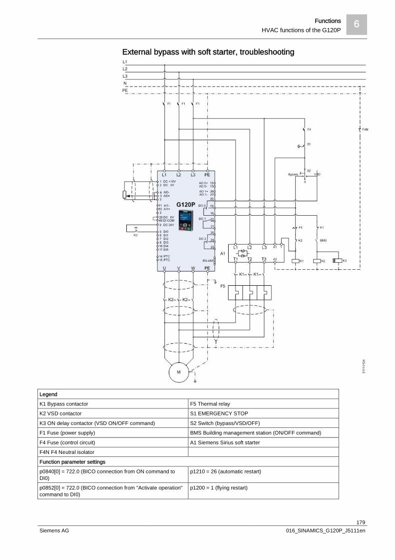
Functions 6HVAC functions of the G120P
179Siemens AG 016_SINAMICS_G120P_J5111en
External bypass with soft starter, troubleshooting
Legend
K1 Bypass contactor F5 Thermal relay
K2 VSD contactor S1 EMERGENCY STOP
K3 ON delay contactor (VSD ON/OFF command) S2 Switch (bypass/VSD/OFF)
F1 Fuse (power supply) BMS Building management station (ON/OFF command)
F4 Fuse (control circuit) A1 Siemens Sirius soft starter
F4N F4 Neutral isolator
Function parameter settings
p0840[0] = 722.0 (BICO connection from ON command toDI0)
p1210 = 26 (automatic restart)
p0852[0] = 722.0 (BICO connection from "Activate operation"command to DI0)
p1200 = 1 (flying restart)

6 FunctionsHVAC functions of the G120P
180Siemens AG 016_SINAMICS_G120P_J5111en
External bypass with soft starter, troubleshooting, 3 contactors
Legend
K1 Bypass contactor F5 Thermal relay
K2 VSD contactor input S1 EMERGENCY STOP
K3 VSD contactor output S2 Switch (bypass/VSD/OFF)
F1 Fuse (power supply) BMS Building management station (ON/OFF command)
F4 Fuse (control circuit) A1 Siemens Sirius soft starter
F4N F4 Neutral isolator
Function parameter settings
p0840[0] = 722.0 (BICO connection from ON command toDI0)
p1210 = 26 (automatic restart)
p0852[0] = 722.0 (BICO connection from "Activate operation"command to DI0)
p1200 = 1 (flying restart)
Functions 6HVAC functions of the G120P
181Siemens AG 016_SINAMICS_G120P_J5111en
6.3.10 Torque monitoringIn many applications, it is desirable to monitor the torque.Using active torque monitoring, the variable speed drive detects critical orhazardous situations and can output a warning to alert a service technician to theproblem.l Detects missing flow rate even if there is no flow rate monitorl Detects torn V-belts even if there is no flow monitorl Detects faulty ball bearings at an early stageThe effect on the torque varies depending on the cause.
If the lack of water supply is due to a closed valve, the required pump torqueincreases in a closed circuit at the same speed.If no water is available due to a leak, for example, the required pump torquedecreases at the same speed.If the torque deviated from the conventional value, the variable speed drive canswitch off the pump and output a warning.
The motor rotates in no-load operation if the v-belts are torn. The required torque atthe same speed drops significantly.The variable speed drive can switch off the fan and output a warning.
A faulty ball bearing increases the required torque at the same speed.The variable speed drive can switch off the drive and output a warning.
NOTICE
Significant deviations from the target torqueSignificant deviations between the actual torque and the target torque cansignificantly reduce the service life of the motor and the driven components, oreven lead to their damage or destruction. Eliminate the cause of the deviation as quickly as possible.
l Use the sensorless vector control (SLVC) for the torque monitoring (p1300) fora higher level of measurement accuracy.
w The permitted torque deviation setting (p2193) must be as accurate as possibleto avoid unnecessary alarms. You can decide when a response (p2181) shouldtake place:- Torque or speed too low- Torque or speed too high- Torque or speed outside the tolerance
l Set the permitted torque deviation in % (+/-) of the conventional value.The setting must be made for each of 3 freely-selectable speeds (p2182,p2183, p2184) on the load curve.
- Input of 3 minimum values for monitoring a torque that is too low(p2186, p2188, p2190)
- Input of 3 maximum values for monitoring a torque that is too high(p2185, p2187, p2189)
- Input of 3 minimum and 3 maximum values for monitoring the torquetolerance(p2185, p2186, p2187, p2188, p2189, p2190)
No water supply to thepump
Torn V-belts
Faulty ball bearings
Control type
Setting the permitteddeviation

6 FunctionsHVAC functions of the G120P
182Siemens AG 016_SINAMICS_G120P_J5111en
a The various setting options allow optimum adaptations to be made to thecorresponding area of application.
The size of the setpoint deviation varies depending on the cause:In the event of a missing water supply or torn V-belts, the deviation is large andsetting the permitted tolerance does not pose any problems.A faulty ball bearing causes smaller deviations and requires the permittedtolerance to be set more accurately.
l Use the adjustable delay time (p2192) to output an alarm. This prevents analarm from being output for temporary deviations.
w To prevent the drive from switching back on automatically after an alarm (A =alarm) or fault (F = fault), the following settings must also be made:
1. Under number p1206, set the parameter "F w/out auto AR" (faults withoutautomatic restart) = 7925, for example
2. Under number p2100, set the parameter "F_no F response" (set fault numberfor fault response) = 7925, for example
3. Under number p2101, set the parameter "Fault response" (fault responsesetting) = 2 (OFF2)
The set value for p1206 and p2100 must correspond with the warning or fault valuethat was set under Load monitoring response (load torque monitoring response)(range 7920-7925). 7925 only applies for the setting M/n out (tolerance monitoringwith fault message F).
Parameters Description
No-load monitoring
p2179 Current limit for no-load detectionIf the variable speed drive current is below this value, the message "no load" is output.
p2180 Delay time for the "no load" message
Stall protection
p2177 Delay time for the "motor locked" message
Speed-dependent torque monitoring
p2181 Load monitoring responseSetting the response for evaluation of load monitoring.0: Load monitoring disabled>0: Load monitoring enabled
p2182 Load monitoring, speed threshold 1
p2183 Load monitoring, speed threshold 2
p2184 Load monitoring, speed threshold 3
p2185 Load monitoring, torque threshold 1, upper
p2186 Load monitoring torque threshold 1, lower
p2187 Load monitoring, torque threshold 2, upper
p2188 Load monitoring torque threshold 2, lower
p2189 Load monitoring, torque threshold 3, upper
p2190 Load monitoring torque threshold 3, lower
p2192 Load monitoring delay timeDelay time for the message "Leave torque monitoring tolerance band"
Delay time
Preventing restarts
Parameters
Functions 6HVAC functions of the G120P
183Siemens AG 016_SINAMICS_G120P_J5111en
For more information about these functions, see the List Manual (function diagram8013 and the parameter list).
6.3.11 Essential Service Mode (fire/emergency operation)The Essential Service Mode (ESM) function ensures that when required, the motoris operated for as long as possible so that, for example, smoke gases can beextracted or people affected by a fire can escape.
NOTICE
Loss of warranty for the variable speed drive in Essential Service ModeIn the case of the Essential Service Mode, the customer can no longer lodge anyclaims for warranty. Essential Service Mode and the faults which arise during thismode are logged in a password-protected memory and can be read by the repaircenter. Only activate the Essential Service Mode in the event of an emergency.
Refer to parameters p3880 to r3889 in the List Manual for more information on theEssential Service Mode.
In order to operate the variable speed drive in the Essential Service Mode, theappropriate degrees of protection and connection and installation guidelinesapplicable to the system should be observed. The current standards can be foundin the ESM G120P guide.
In order to improve air circulation in stairwells, slight underpressure is frequentlygenerated using ventilation control. With this control, a fire would mean that smokegases enter into the stairwell. This would then mean that the stairway would beblocked as an escape or evacuation route.Using the Essential Service Mode function, the ventilation switches over to controlan overpressure. This prevents the propagation of smoke gases in the stairwell,thereby keeping the stairs free as an escape route.
The Essential Service Mode is activated by interconnecting p3880 with a digitalinput of your choice.If you wish to activate the Essential Service Mode with the digital input, forexample, set p3880 = 722.3.
NOTICE
Only 1 command source for the Essential Service ModeThe Essential Service Mode can only be switched on from precisely onecommand source. The setting of the source for the Essential Service Mode viap3880 is always referred to the data set that is currently active. Do not logically combine the digital input for the Essential Service Mode with
any other functions. Detailed information is given in the ESM manual.
The last setpoint recognized is taken as the emergency setpoint in the factorysetting. You can use p3881 to define another value:l p3881 = 0: Last recognized setpoint (factory setting)
Application example
Activating the EssentialService Mode function
6 FunctionsHVAC functions of the G120P
184Siemens AG 016_SINAMICS_G120P_J5111en
l p3881 = 1: Fixed setpoint 15l p3881 = 2: Analog setpointl p3881 = 3: Fieldbusl p3881 = 4: Technology controllerNew to FW4.6 and laterl p3881 = 6: OFF1 -> motor stops with normal ramp timel p3881 = 7: OFF2 -> motor runs to a stop
If you specify the emergency setpoint via the analog setpoint, fieldbus, ortechnology controller, you must ensure the appropriate monitoring so that analternative setpoint can be used in the event of failure.Possible forms of monitoring for the different setpoint sources:l Analog setpoint: Using F03505l Fieldbus status in r2043l Technology controller r2349You will find additional details on this in the List Manual in the function diagrams forEssential Service Mode, setpoint channel, and technology controller.
When in the factory setting, if the setpoint is lost, the drive continues using the lastrecognized setpoint. p3882 can be used to switch to the following values:l p3882 = 0: Last recognized setpoint (factory setting)l p3882 = 1: Fixed speed setpoint which is defined in p1015l p3882 = 2: Maximum speed (value of p1082)
For the technology controller to be able to specify the emergency setpoint, it mustbe activated (p2200 = 1) and set as the main setpoint (p2251 = 0).
l Emergency setpoint via p3881 = 0, 1, 2, 3Depending on the system, it may be necessary to invert the setpoint on site forthe Essential Service Mode. You can therefore use p3883 to determine thedirection of rotation of the emergency setpoint. To do this, p3883 must belinked with a free digital input, e.g. p3883 = r722.12.– p3883 = 0 -> normal direction of rotation in an emergency,– p3883 = 1 -> inverted direction of rotation in an emergency.
l Emergency setpoint via p3881 = 4If the emergency setpoint is specified using the technology controller, it isdepicted using variables within the process and depends on these. Inversionusing a digital input is therefore locked in such cases and must be implementedin the technology controller.
l If the motor is running in bypass operation when the emergency happens, theuser must query the "Bypass control/status word" (r1261) and make anappropriate interconnection to ensure that the motor is switched to the variablespeed drive and continues to run with the emergency setpoint.
l If the variable speed drive has failed in the Essential Service Mode because ofan internal fault and if it cannot be switched back on using the automatic restartfunction, the user can interconnect bit 7 of the status word for the automaticrestart (r1214.7) with p1266 to operate the motor directly on the line. You willfind additional information about bypass operation in the Bypass section.
Direction of rotation inthe Essential ServiceMode
Bypass operation in theEssential Service Mode
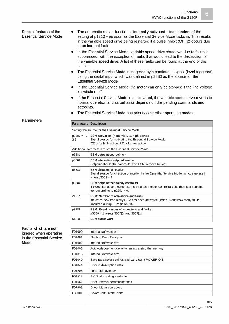
Functions 6HVAC functions of the G120P
185Siemens AG 016_SINAMICS_G120P_J5111en
l The automatic restart function is internally activated – independent of thesetting of p1210 – as soon as the Essential Service Mode kicks in. This resultsin the variable speed drive being restarted if a pulse inhibit (OFF2) occurs dueto an internal fault.
l In the Essential Service Mode, variable speed drive shutdown due to faults issuppressed, with the exception of faults that would lead to the destruction ofthe variable speed drive. A list of these faults can be found at the end of thissection.
l The Essential Service Mode is triggered by a continuous signal (level-triggered)using the digital input which was defined in p3880 as the source for theEssential Service Mode.
l In the Essential Service Mode, the motor can only be stopped if the line voltageis switched off.
l If the Essential Service Mode is deactivated, the variable speed drive reverts tonormal operation and its behavior depends on the pending commands andsetpoints.
l The Essential Service Mode has priority over other operating modes
Parameters Description
Setting the source for the Essential Service Mode
p3880 = 722.3
ESM activation (here, via DI3, high-active)Signal source for activating the Essential Service Mode722.x for high active, 723.x for low active
Additional parameters to set the Essential Service Mode
p3881 ESM setpoint source0 to 4
p3882 ESM alternative setpoint sourceSetpoint should the parameterized ESM setpoint be lost
p3883 ESM direction of rotationSignal source for direction of rotation in the Essential Service Mode, is not evaluatedwhen p3881 = 4
p3884 ESM setpoint technology controllerIf p3884 is not connected up, then the technology controller uses the main setpointcorresponding to p2251 = 0.
r3887 ESM: Number of activations and faultsIndicates how frequently ESM has been activated (index 0) and how many faultsoccurred during ESM (index 1).
p3888 ESM: Reset number of activations and faultsp3888 = 1 resets 3887[0] and 3887[1].
r3889 ESM status word
F01000 Internal software error
F01001 Floating Point Exception
F01002 Internal software error
F01003 Acknowledgement delay when accessing the memory
F01015 Internal software error
F01040 Save parameter settings and carry out a POWER ON
F01044 Error in description data
F01205 Time slice overflow
F01512 BICO: No scaling available
F01662 Error, internal communications
F07901 Drive: Motor overspeed
F30001 Power unit: Overcurrent
Special features of theEssential Service Mode
Parameters
Faults which are notignored when operatingin the Essential ServiceMode

6 FunctionsProtection functions
186Siemens AG 016_SINAMICS_G120P_J5111en
F30002 Power unit: DC-link voltage overvoltage
F30003 Power unit: DC-link voltage undervoltage
F30004 Power unit: Overtemperature heat sink inverter
F30005 Power unit: Overload I2t
F30017 Power unit: Hardware current limit has responded too often
F30021 Power unit: Ground fault
F30024 Power unit: Overtemperature, thermal model
F30025 Power unit: Chip overtemperature
F30027 Power unit: Time monitoring for DC link pre-charging
F30036 Power unit: Internal overtemperature
F30071 No new actual values received from the Power Module
F30072 Setpoints can no longer be transferred to the Power Module
F30105 PU: Actual value sensing fault
F30662 Internal communication error
F30664 Fault during power-up
F30802 Power unit: Time slice overflow
F30805 Power unit: EPROM checksum error
F30809 Power unit: Switching information not valid
6.4 Protection functionsThe variable speed drive offers protection functions against overtemperature andovercurrent for both the variable speed drive as well as the motor. Furthermore, thevariable speed drive protects itself against an excessively high DC link voltagewhen the motor is in generator mode.
6.4.1 Variable speed drive temperature monitoringThe variable speed drive protects itself against overtemperature with differentmonitoring functions:l I2t monitoring (alarm A07805, fault F30005)
The I2t monitoring measures the actual utilization on the basis of a currentreference value.The parameter r0036 [%] displays the current utilization in %. As long as theactual current does not exceed the reference value, then the utilization in r0036= 0.
l Monitoring the chip temperature of the power unit (alarm A05006, fault F30024)The variable speed drive monitors the difference in temperature between thepower chip (IGBT) and the heat sink. The measured values are in r0037[1] [°C].
l Heat sink monitoring (alarm A05000, fault F30004)The variable speed drive monitors the heat sink temperature of the PowerModule. The values are in r0037[0] [°C].
The variable speed drive temperature is essentially determined by the resistivelosses of the output current and the switching losses which occur when pulsing themotor. Parameter p0290 defines how the variable speed drive responds to anexcessively high temperature.
Parameters Description
P0290 Power unit overload reaction (factory setting: 2Setting the reaction to a thermal overload of the power unit:
Variable speed driveresponse

Functions 6Protection functions
187Siemens AG 016_SINAMICS_G120P_J5111en
Parameters Description
0 Reduce output current (in sensorless vector control mode) or speed (in V/f controlmode)
1 No reduction, shutdown when overload threshold is reached (F30024)
2 Reduce pulse frequency and output current (in sensorless vector control mode) orpulse frequency and speed (in V/f mode)
3 Reduce pulse frequency
P0292 Power unit temperature warning threshold (factory setting: Heat sink [0] 5 °C, power semiconductor [1] 15 °C)The value is set as a difference to the shutdown temperature.
6.4.2 Motor temperature monitoring using a temperature sensorWhen operating below the rated speed, the cooling effect of the fan mounted onthe motor shaft is reduced. To ensure that the motors are protected againstoverheating under such circumstances, we recommend installing a temperaturesensor.
You can use one of the following sensors to protect the motor againstovertemperature: Temperature switch (e.g. bimetallic switch) PTC sensor KTY84 sensorConnect the temperature sensor of the motor to terminals 14 and 15 of the variablespeed drive.
The variable speed drive evaluates the temperature switch as follows:l Overtemperature alarm (A07910):
The variable speed drive interprets a resistance ≥ 100 Ω as an open-circuittemperature switch and responds with an alarm.
l Overtemperature fault (F07011):If p0610 = 1 or p0610 = 2, in addition to an alarm, the variable speed driveresponds to this with a fault.
The variable speed drive evaluates the PTC sensor as follows:l Overtemperature alarm (A07910):
For a resistance > 1,650 Ω, the variable speed drive responds with an alarm.l Overtemperature fault (F07011):
If p0610 = 1 or p0610 = 2, in addition to an alarm, the variable speed driveresponds to this with a fault.
l Alarm and fault sensor monitoring (A07015 or F07016):– The variable speed drive interprets a resistance < 20 Ω as a short-circuit.– The variable speed drive responds to the short-circuit with a warning. If thealarm is present longer than 100 ms, then this is followed by a fault.
Connecting atemperature sensor
Temperature switch
PTC sensor
6 FunctionsProtection functions
188Siemens AG 016_SINAMICS_G120P_J5111en
NOTICE
False polarity in the KTY sensorIf a KTY sensor is connected with the incorrect polarity, this can destroy the motordue to overheating, as the variable speed drive cannot detect a motorovertemperature condition. Ensure the correct polarity when connecting the KTY sensor.
The variable speed drive evaluates the KTY sensor as follows:l Temperature measurement:
The variable speed drive determines the motor temperature in the range from -48 °C to 248 °C.
l Overtemperature alarm (A07910):The variable speed drive signals an alarm for a motor temperature > p0604.
l Overtemperature fault (F07011):The variable speed drive signals a fault in the following cases:–Primarily in the case of a motor temperature > p0605.– Also in the case of a motor temperature > p0604 if p0610 = 1 or p0610 = 2.
l Warning and fault sensor monitoring (A07015 or F07016):– Wire breakage:The variable speed drive interprets a resistance > 2,120 Ω as a wire breakage.– Short-circuit:The variable speed drive interprets a resistance < 50 Ω as a short-circuit.– The variable speed drive responds to a wire breakage or short-circuit with analarm.If the alarm lasts for longer than 100 ms, the fault ensues.
Parameters Description
p0335 Specify the motor cooling
0 Self-ventilated - with fan on the motor shaft (factory setting)
1 Forced ventilation - with a separately driven fan
2 Self-ventilated and inner cooling (open-circuit cooling)
3 Forced ventilation and inner cooling (open-circuit cooling)
p0601 Motor temperature sensor type
0 No sensor (factory setting)
1 PTC (→ p0604)
2 KTY84 (→ p0604, p0605)
4 Temperature switch
p0604 Motor temperature alarm threshold (factory setting 130 °C)
p0605 Motor temperature fault threshold (factory setting: 145° C)Setting for KTY84 sensor. The parameter has no significance for a PTC sensor.
p0610 Motor overtemperature responseDetermines the response when the motor temperature reaches the alarm thresholdp0604.
0 Alarm (A07910), but no response of the motor.
1 Alarm (A07910) and reduction of the current limit (factory setting) - this reduces themotor speed.
2 Fault (F07011) and shutdown.
p0640 Current limit (input in A)
Parameters for thetemperature monitoring

Functions 6Protection functions
189Siemens AG 016_SINAMICS_G120P_J5111en
Additional information on the motor temperature monitoring can be found infunction diagram 8016 of the List Manual.
6.4.3 Protecting the motor by calculating the motor temperatureThe temperature calculation is only possible in the sensorless vector control mode(p1300 ≥ 20) and functions by calculating a thermal motor model.
Parameters Description
P0621 = 1 Motor temperature measurement after restarting
0 No temperature identification (factory setting)
1 Temperature identification after the motor is switched on for the first time
2 Temperature measurement each time that the motor is switched on
P0622 Magnetization time of the motor for temperature measurement after starting(set automatically as the result of motor data identification)
P0625 = 20 Ambient motor temperatureEnter the ambient motor temperature in °C at the instant that the motor data is acquired(factory setting: 20 °C).The difference between the motor temperature and motor environment (P0625) must liewithin a tolerance range of approx. ± 5 °C.
6.4.4 Overcurrent protectionDuring sensorless vector control, the motor current remains within the currenttorque limits set.During V/f control, the maximum current controller (Imax controller) protects themotor and variable speed drive against overload by limiting the output current.
If an overload situation occurs, the speed and stator voltage of the motor arereduced until the current is within the permissible range. If the motor is in generatormode, i.e. it is being driven by the connected machine, the Imax controller increasesthe speed and stator voltage of the motor to reduce the current.
The variable speed drive load is only reduced if the motor torque decreases atlower speeds (e.g. for fans).In the generator mode, the current only decreases if the torque decreases at ahigher speed.
You only have to change the factory settings of the Imax controller if the drive tendsto oscillate when it reaches the current limit or it is shut down due to overcurrent.
Parameters Description
p0305 Rated motor current
p0640 Motor current limit
p1340 Proportional gain of the I-max controller for speed reduction
p1341 Integral time of the I-max controller for speed reduction
r0056.13 Status: Imax controller active
r1343 Speed output of Imax controllerShows the amount to which the Imax controller reduces the speed.
Parameters to sense thetemperature withoutusing a temperaturesensor
Method of operation ofImax controller
Settings

6 FunctionsProtection functions
190Siemens AG 016_SINAMICS_G120P_J5111en
For more information about this function, see function diagram 1690 in the ListManual.In the case of overvoltage, the motor switches off with OFF2 and flags the faultF07801.
6.4.5 Protection against short circuitShort-circuit protection is covered by the function Overcurrent protection [ 189] .The G120P detects the short-circuit via the rapid increase in current and outputsthe fault code F30022. It also provides the location of the short-circuit via theadditional bit:l Bit 0: Short-circuit in U phasel Bit 1: Short-circuit in V phasel Bit 2: Short-circuit in W phaseIn the case of a short-circuit at the output terminals on the motor side of thevariable speed drive, the fault code F07807 appears.The following alarms are also output:l A30031 power unit: Hardware current limiting in phase Ul A30032 power unit: Hardware current limiting in phase Vl A30033 power unit: Hardware current limiting in phase WIn the event of a short-circuit, the motor switches off with OFF2.
6.4.6 Protection against ground faultGround fault protection is covered by the function Overcurrent protection [ 189] .As for a short-circuit, the G120P detects the ground fault via the rapid increase incurrent. In the case of a ground fault, however, the total current does not equal 0.The trip values for ground-fault monitoring can be set via p0287.A ground fault is displayed at r3113.05 and also using fault codes F30001 andF30021. In the case of a ground fault in the DC link, fault code F30027 appears.In the event of a short-circuit, the motor is switched off with OFF2.
6.4.7 Phase failureIf a phase should fail, the G120P continues to run up to approx. 50% of the speed,for example in fans and pumps.The value depends on the motor load. In the case of a greater motor load, forexample, in compressors, the achievable speed is significantly lower.In the case of a very high load, the speed can drop to 0. In this case, the motorswitches off with OFF2 and displays the phase failure with the fault code F30011.The fault code for under-voltage in the DC link (F30003) can also appear in theevent of a phase failure.You can add this fault to exception list p1206 to prevent an automatic restart. Forfurther information, refer to Automatic restart [ 122].In this way, you can prevent frequent restart attempts that can lead to the motorwinding overheating due of a lack of cooling.You can also prevent this by reducing the number of restart attempts. By reducingthe G120P's starting current, the time interval compared to conventional variablespeed drives can, however, be significantly less than 6 minutes.

Functions 6Function & logic blocks (BICO technology)
191Siemens AG 016_SINAMICS_G120P_J5111en
6.4.8 Limiting the maximum DC-link voltageAn induction motor operates as a generator if it is driven by the connected load. Agenerator converts mechanical power into electrical power.The electrical power flows back into the variable speed drive and causes VDC inthe variable speed drive to increase.Above a critical DC-link voltage both the variable speed drive and the motor will bedamaged. Before the voltage can reach critical levels, however, the variable speeddrive switches the motor off with the fault message "DC link overvoltage".
To the extent the application permits, the VDC_max controller prevents the DC-linkvoltage from reaching critical levels. The VDC_max controller increases the ramp-down time of the motor during braking, so that the motor feeds back only as littlepower to the variable speed drive as is covered by the losses in the variable speeddrive.The VDC_max controller is not suitable for applications that require permanentmotor generator operation.There are two different groups of parameters for the VDC_max controller,depending on whether the motor is being operated with V/f control or sensorlessvector control.
Parameter forV/f control
Parameter forvector control
Description
p1280 = 1 p1240 = 1 VDC controller or VDC monitoring configuration(factory setting: 1)1: Enable VDC_max controller
r1282 r1242 VDC_max controller switch-in levelShows the value of the DC-link voltage above which the VDC_maxcontroller is active
p1283 p1243 VDC_max controller dynamic factor (factory setting: 100 %)Scaling of the control parameters p1290, p1291, and p1292
p1290 p1250 VDC_max controller proportional gain (factory setting: 1)
p1291 p1251 VDC_max controller integral time(factory setting p1291:40 ms, factory setting p1251:0 ms)
p1292 p1252 VDC_max controller rate time(factory setting p1292:10 ms, factory setting p1252:0 ms)
p1294 p1254 VDC_max controller automatic ON level detection(factory setting p1294:0, factory setting p1254:1)Activates or deactivates the automatic detection of the VDC_maxcontrol's switch-on levels0: Automatic detection disabled1: Automatic detection enabled
p0210 p0210 Unit supply voltageIf p1254 or p1294 = 0, the variable speed drive uses this parameterto calculate the intervention thresholds of the VDC_max controller.Set this parameter to the actual value of the input voltage.
For more information about this function, see function diagram 6320 or 6220 in theList Manual.
6.5 Function & logic blocks (BICO technology)
6.5.1 Basic principlesOpen/closed-loop control functions, communication functions as well as diagnosticand operator functions are implemented in the variable speed drive. Every functioncomprises one or several BICO blocks that are interconnected with one another.
How does the motorgenerate overvoltage?
Protecting the motor andvariable speed driveagainst overvoltage
Operating principle
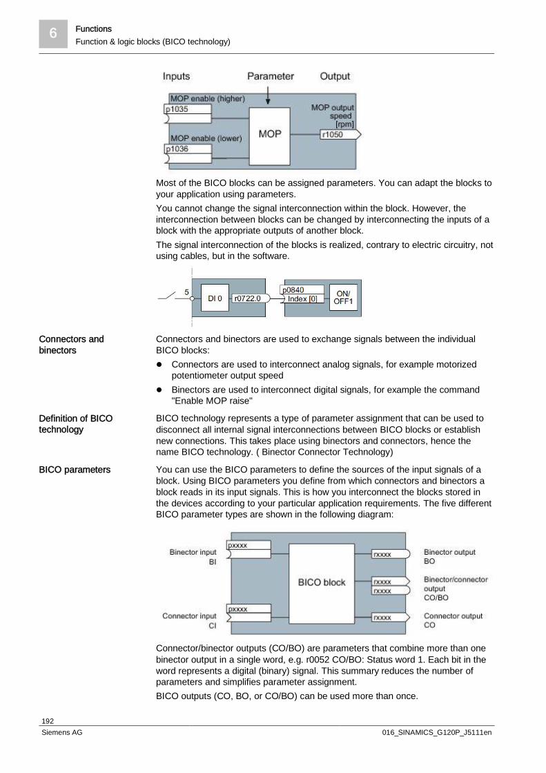
6 FunctionsFunction & logic blocks (BICO technology)
192Siemens AG 016_SINAMICS_G120P_J5111en
Most of the BICO blocks can be assigned parameters. You can adapt the blocks toyour application using parameters.You cannot change the signal interconnection within the block. However, theinterconnection between blocks can be changed by interconnecting the inputs of ablock with the appropriate outputs of another block.The signal interconnection of the blocks is realized, contrary to electric circuitry, notusing cables, but in the software.
Connectors and binectors are used to exchange signals between the individualBICO blocks:l Connectors are used to interconnect analog signals, for example motorized
potentiometer output speedl Binectors are used to interconnect digital signals, for example the command
"Enable MOP raise"
BICO technology represents a type of parameter assignment that can be used todisconnect all internal signal interconnections between BICO blocks or establishnew connections. This takes place using binectors and connectors, hence thename BICO technology. ( Binector Connector Technology)
You can use the BICO parameters to define the sources of the input signals of ablock. Using BICO parameters you define from which connectors and binectors ablock reads in its input signals. This is how you interconnect the blocks stored inthe devices according to your particular application requirements. The five differentBICO parameter types are shown in the following diagram:
Connector/binector outputs (CO/BO) are parameters that combine more than onebinector output in a single word, e.g. r0052 CO/BO: Status word 1. Each bit in theword represents a digital (binary) signal. This summary reduces the number ofparameters and simplifies parameter assignment.BICO outputs (CO, BO, or CO/BO) can be used more than once.
Connectors andbinectors
Definition of BICOtechnology
BICO parameters

Functions 6Function & logic blocks (BICO technology)
193Siemens AG 016_SINAMICS_G120P_J5111en
A new feature of the G120P is the inclusion of logic blocks, which enable logicalconnectives and calculations to be made.
When do you need to use BICO technology?BICO technology allows you to adapt the variable speed drive to a wide range ofdifferent requirements with ease. This does not necessarily have to involve highlycomplex functions.Example 1: Assign a different function to a digital input.Example 2: Switch the speed setpoint from the fixed speed to the analog input.
What precautions should you take when using BICO technology?Always apply caution when handling internal interconnections. Note which changesyou make as you go along since the process of analyzing them later can be quitedifficult.The STARTER commissioning tool offers various screens that make it much easierfor you to use BICO technology. The signals that you can interconnect aredisplayed in plain text, which means that you do not need any prior knowledge ofBICO technology.
What sources of information do you need to help you set parameters using BICOtechnology?This manual is sufficient for simple signal interconnections, e.g. assigning adifferent significance to the digital inputs.The parameter list in the List Manual is sufficient for signal interconnections that gobeyond just simple ones.You can also refer to the function diagrams in the List Manual for complex signalinterconnections.
6.5.2 ExampleA conveyor system is to be configured in such a way that it can only start when twosignals are present simultaneously. These could be the following signals, forexample:l The oil pump is running, although the required pressure level is not reached
until after 5 secondsl The protective door is closedThe task is realized by inserting free blocks between digital input 0 and the internalON/OFF1 command and interconnecting them.
The signal of digital input 0 (DI 0) is fed through a time block (PDE 0) and isinterconnected with the input of a logic block (AND 0). The signal of digital input 1(DI 1) is interconnected to the second input of the logic block. The logic blockoutput issues the ON/OFF1 command to switch on the motor.
Shifting a basic PLCfunctionality into thevariable speed drive

6 FunctionsFunction & logic blocks (BICO technology)
194Siemens AG 016_SINAMICS_G120P_J5111en
Parameter settings
Parameters Description
p20161 = 5 The time block is enabled by assigning to runtime group 5(time slice of 128 ms)
p20162 = 430 Run sequence of the time block within runtime group 5(processing before the AND logic block)
p20032 = 5 The AND logic block is enabled by assigning to runtime group 5(time slice of 128 ms)
p20033 = 440 Run sequence of the AND logic block within runtime group 5(processing after the time block)
p20159 =5000.00
Setting the delay time [ms] of the time module: 5 s
p20158 =722.0
Wiring the DI 0 status to the time module inputr0722.0 = parameter that displays the status of digital input 0
p20030 [0] =20160
Interconnecting the time block to the first AND input
p20030 [1] =722.1
Wiring the DI 1 status to the second AND inputr0722.1 = parameter that displays the status of digital input 1
p0840 =20031
Interconnecting the AND output to the control command ON/OFF1
Explanation of the example using the ON/OFF1 commandParameter P0840[0] is the input of the "ON/OFF1 command" block of the variablespeed drive.Parameter r20031 is the output of the AND block. To interconnect the ON/OFF1command with the output of the AND block, set P0840 to 20031.
Principle when connecting BICO blocks using BICO technologyAn interconnection between two BICO blocks comprises a connector or binectorand a BICO parameter. The interconnection is always established from theperspective of the input of a particular BICO block. This means that the output ofan upstream block must always be assigned to the input of a downstream block.Be sure to enter the number of the connector/binector from which the requiredinput signals are read in a BICO parameter.This interconnection logic involves the question: Where does the signal comefrom?
Functions 6Function & logic blocks (BICO technology)
195Siemens AG 016_SINAMICS_G120P_J5111en
NOTICE
Loss of BICO settingsFor the basic commissioning, you determine the function of the interfaces for yourvariable speed drive via predefined settings using the macro parameter (p0015). Please be aware that if you subsequently select a different predefined setting
for the function of the interfaces, then all BICO interconnections that youchanged will be lost.
6.5.3 Free function blocksIn addition to the BICO blocks for normal control functionality, further BICO blocks(the "free function blocks") are available for additional functions.None of the free function blocks in the variable speed drive are used in the factorysetting.
The following free function blocks are available:l Logic blocks AND, OR, XOR, and NOTl Arithmetic blocks ADD, SUB, MUL, DIV, AVA (device for forming absolute
values), NCM (numeric comparator), and PLI (polyline)l Time modules MFP (pulse generator), PCL (pulse shortening), PDE (ON
delay), PDF (OFF delay), and PST (pulse stretching)l Memory: RSR (RS flip-flop), DSR (D flip-flop)l Switches NSW (numeric change-over switch) and BSW (binary change-over
switch)l Controllers LIM (limiter), PT1 (smoothing element), INT (integrator), and DIF
(differentiating element)l Limit value monitoring (LVM)You will find an overview of all of the free function blocks and their parameters inthe List Manual, in Chapter "Function diagrams" in Section "Free function blocks"(function diagrams 7210 ff).
w Proceed as follows to use a free function block:
1. Select the function block via the function diagram in the parameter list. This iswhere you will find all necessary parameters for interconnecting the block.
2. Assign the block to a runtime group.
3. Define the run sequence within the runtime group. This is only required if youhave assigned several blocks in the same runtime group.
4. Interconnect the block's inputs and outputs with the corresponding signals onthe variable speed drive.
The runtime groups are calculated at different intervals (time slices).
Activating the free blocks
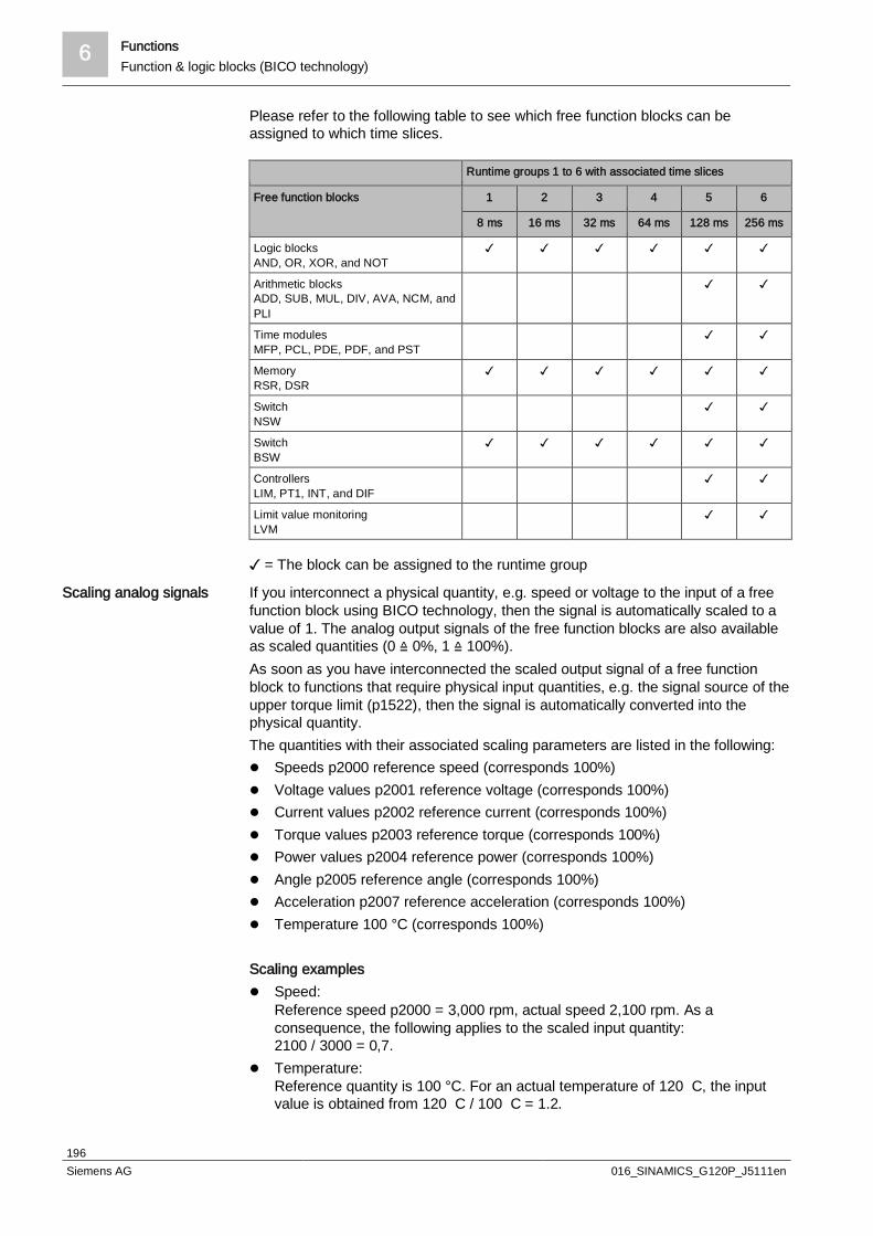
6 FunctionsFunction & logic blocks (BICO technology)
196Siemens AG 016_SINAMICS_G120P_J5111en
Please refer to the following table to see which free function blocks can beassigned to which time slices.
Runtime groups 1 to 6 with associated time slices
Free function blocks 1 2 3 4 5 6
8 ms 16 ms 32 ms 64 ms 128 ms 256 ms
Logic blocksAND, OR, XOR, and NOT
Arithmetic blocksADD, SUB, MUL, DIV, AVA, NCM, andPLI
Time modulesMFP, PCL, PDE, PDF, and PST
MemoryRSR, DSR
SwitchNSW
SwitchBSW
ControllersLIM, PT1, INT, and DIF
Limit value monitoringLVM
= The block can be assigned to the runtime group
If you interconnect a physical quantity, e.g. speed or voltage to the input of a freefunction block using BICO technology, then the signal is automatically scaled to avalue of 1. The analog output signals of the free function blocks are also availableas scaled quantities (0 ≙ 0%, 1 ≙ 100%).As soon as you have interconnected the scaled output signal of a free functionblock to functions that require physical input quantities, e.g. the signal source of theupper torque limit (p1522), then the signal is automatically converted into thephysical quantity.The quantities with their associated scaling parameters are listed in the following:l Speeds p2000 reference speed (corresponds 100%)l Voltage values p2001 reference voltage (corresponds 100%)l Current values p2002 reference current (corresponds 100%)l Torque values p2003 reference torque (corresponds 100%)l Power values p2004 reference power (corresponds 100%)l Angle p2005 reference angle (corresponds 100%)l Acceleration p2007 reference acceleration (corresponds 100%)l Temperature 100 °C (corresponds 100%)
Scaling examplesl Speed:
Reference speed p2000 = 3,000 rpm, actual speed 2,100 rpm. As aconsequence, the following applies to the scaled input quantity:2100 / 3000 = 0,7.
l Temperature:Reference quantity is 100 °C. For an actual temperature of 120 C, the inputvalue is obtained from 120 C / 100 C = 1.2.
Scaling analog signals

Functions 6Function & logic blocks (BICO technology)
197Siemens AG 016_SINAMICS_G120P_J5111en
Enter limits within the function blocks as scaled values. The scaled value can becalculated as follows using the reference parameters:Scaled limit value = physical limit value or value of the reference parameter.The reference parameter assignment can be found in the parameter list in theindividual parameter descriptions.
Example: Logic combination of two digital inputs
w You want to switch on the motor via digital input 0 and also via digital input 1:
1. Activate a free OR block by assigning it to a runtime group, and define the runsequence.
2. Interconnect the status signals of the two digital inputs DI 0 and DI 1 via BICOto the two inputs of the OR block.
3. Interconnect the OR block output with the internal ON command (p0840).
Parameters Description
p20048 = 1 Assignment of block OR 0 to runtime group 1 (factory setting: 9999)The block OR 0 is calculated in the time slice with 8 ms
p20049 = 60 Definition of run sequence within runtime group 1(factory setting: 60)Within one runtime group, the block with the smallest value is calculated first.
p20046 [0] =722.0
Interconnection of first OR 0 input (factory setting: 0)The first OR 0 input is linked to digital input 0 (r0722.0)
p20046 [1] =722.1
Interconnection of second OR 0 input (factory setting: 0)The second OR 0 input is linked to digital input 1 (r0722.1)
p0840 =20047
Interconnection of the OR 0 output (factory setting: 0)The OR 0 output (r20047) is connected with the motor's ON command
You can find additional information in the following manuals:l "Free function blocks" Function Manual
(http://support.automation.siemens.com/WW/view/en/35125827)l "Description of the DCC standard blocks" Function Manual
(http://support.automation.siemens.com/WW/view/en/29193002)

7 CommunicationOverview
198Siemens AG 016_SINAMICS_G120P_J5111en
7 Communication
7.1 OverviewThe CU230P-2 has various interfaces for communication.
The following interfaces are available regardless of the type ordered:l Interface for BOP-2 or IOPl USB for communication with the STARTER software
The following interfaces are also available depending on the type ordered:l The standard CU in the G120P BT bundle, the CU230P-2 BT, has an RS485
interface for connecting to various fieldbus systems (USS, Modbus RTU, andBACnet MS/TP.
l CU230P-2 DP has a SUB-D interface for connecting to PROFIBUS DP.l CU230P-2 CAN has a SUB-D interface for connecting to CANopen.l CU230P-2 PN has an RJ45 interface (Ethernet) for connecting to PROFINET.
123
6
5
4
89
1011
1
52
34
10
8
6
7
9
9
10
Voltage
Memory card slot (MMC or SD card)
DIP switch for AI0and AI1 (terminals3/4 and 10/11)
LG-NI1000 DIP switch AI2( / )terminals 50 51
Interface for an operator panel (IOP or BOP-2)
Digital outputs
Current
Terminal designationTerminal strip
USB interface for STARTERStatus LED
DIP switch for fieldbus address( )for PROFINET no function
Switch for bus terminating resistor
Cur
rent
Example:
Address = 10
AI0AI1
OffOnBit 0 (1)Bit 1 (2)Bit 2 (4)Bit 3 (8)Bit 4 (16)Bit 5 (32)Bit 6 (64)
RDYBF---LNK1, nur bei PROFINETLNK2, nur bei PROFINET
31 +24V IN32 GND IN-35 +10V OUT36 GND50 AI 2+/NI1000
51 GND52 AI 3+/NI1000
53 GND----10 AI 1+11 AI 1-26 AO 1+27 GND
1 +10V OUT2 GND3 AI 0+4 AI 0-12 AO 0+13 GND21 DO 1 NO22 DO 1 COM14 T1 MOTOR15 T2 MOTOR9 +24V OUT28 GND69 DI COM5 DI 06 DI 17 DI 28 DI 316 DI 417
1234
1213212218
19
2324
20
14159
28695678
1617 DI 5
Analo
gIn/
Out
Analo
gIn/O
ut
3132
353650515253
10112627
Analo
gIn/O
utDi
gital
In/Ou
t
25
18DO 0 NC
19DO 0 NO
20DO 0 COM
23DO 2 NC
24DO 2 NO
25DO 2 COM
8
2
NI1
000
LG-
7.2 Interface for BOP-2 or IOPThe operating device and display device for the CU are attached to this interface.The following two devices are available:l BOP-2 basic operator panell IOP intelligent operator panel
The devices are automatically detected by the CU. No configuration is required forthese interfaces.
Overview of theinterfaces
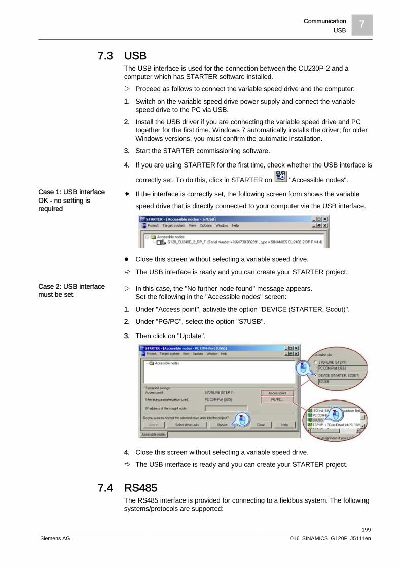
Communication 7USB
199Siemens AG 016_SINAMICS_G120P_J5111en
7.3 USBThe USB interface is used for the connection between the CU230P-2 and acomputer which has STARTER software installed.
w Proceed as follows to connect the variable speed drive and the computer:
1. Switch on the variable speed drive power supply and connect the variablespeed drive to the PC via USB.
2. Install the USB driver if you are connecting the variable speed drive and PCtogether for the first time. Windows 7 automatically installs the driver; for olderWindows versions, you must confirm the automatic installation.
3. Start the STARTER commissioning software.
4. If you are using STARTER for the first time, check whether the USB interface is
correctly set. To do this, click in STARTER on "Accessible nodes".
If the interface is correctly set, the following screen form shows the variablespeed drive that is directly connected to your computer via the USB interface.
l Close this screen without selecting a variable speed drive.
a The USB interface is ready and you can create your STARTER project.
w In this case, the "No further node found" message appears.Set the following in the "Accessible nodes" screen:
1. Under "Access point", activate the option "DEVICE (STARTER, Scout)".
2. Under "PG/PC", select the option "S7USB".
3. Then click on "Update".
4. Close this screen without selecting a variable speed drive.
a The USB interface is ready and you can create your STARTER project.
7.4 RS485The RS485 interface is provided for connecting to a fieldbus system. The followingsystems/protocols are supported:
Case 1: USB interfaceOK - no setting isrequired
Case 2: USB interfacemust be set
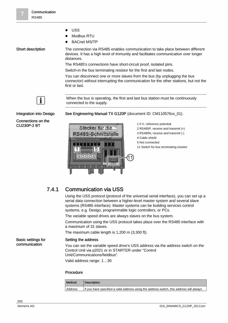
7 CommunicationRS485
200Siemens AG 016_SINAMICS_G120P_J5111en
l USSl Modbus RTUl BACnet MS/TP
The connection via RS485 enables communication to take place between differentdevices. It has a high level of immunity and facilitates communication over longerdistances.The RS485's connections have short-circuit proof, isolated pins.Switch-in the bus terminating resistor for the first and last nodes.You can disconnect one or more slaves from the bus (by unplugging the busconnector) without interrupting the communication for the other stations, but not thefirst or last.
When the bus is operating, the first and last bus station must be continuouslyconnected to the supply.
See Engineering Manual TX G120P (document ID: CM110576xx_01).
1 0 V, reference potential2 RS485P, receive and transmit (+)3 RS485N, receive and transmit (-)4 Cable shield5 Not connected11 Switch for bus terminating resistor
7.4.1 Communication via USSUsing the USS protocol (protocol of the universal serial interface), you can set up aserial data connection between a higher-level master system and several slavesystems (RS485 interface). Master systems can be building services controlsystems, e.g. Desigo, programmable logic controllers, or PCs.The variable speed drives are always slaves on the bus system.Communication using the USS protocol takes place over the RS485 interface witha maximum of 31 slaves.The maximum cable length is 1,200 m (3,300 ft).
Setting the addressYou can set the variable speed drive's USS address via the address switch on theControl Unit via p2021 or in STARTER under "ControlUnit/Communications/fieldbus".Valid address range: 1…30
Procedure
Method Description
Address If you have specified a valid address using the address switch, this address will always
Short description
Integration into Desigo
Connections on theCU230P-2 BT
Basic settings forcommunication
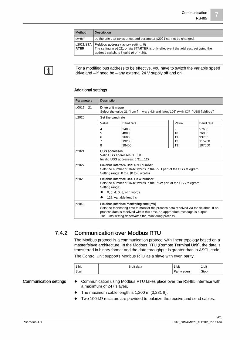
Communication 7RS485
201Siemens AG 016_SINAMICS_G120P_J5111en
Method Description
switch be the one that takes effect and parameter p2021 cannot be changed.
p2021/STARTER
Fieldbus address (factory setting: 0)The setting in p2021 or via STARTER is only effective if the address, set using theaddress switch, is invalid (0 or > 30).
For a modified bus address to be effective, you have to switch the variable speeddrive and – if need be – any external 24 V supply off and on.
Additional settings
Parameters Description
p0015 = 21 Drive unit macroSelect the value 21 (from firmware 4.6 and later: 108) (with IOP: "USS fieldbus")
p2020 Set the baud rate
Value Baud rate Value Baud rate
45678
2400480096001920038400
910111213
576007680093750115200187500
p2021 USS addressesValid USS addresses: 1…30Invalid USS addresses: 0.31…127
p2022 Fieldbus interface USS PZD numberSets the number of 16-bit words in the PZD part of the USS telegramSetting range: 0 to 8 (0 to 8 words)
p2023 Fieldbus interface USS PKW numberSets the number of 16-bit words in the PKW part of the USS telegramSetting range:l 0, 3, 4: 0, 3, or 4 wordsl 127: variable lengths
p2040 Fieldbus interface monitoring time [ms]Sets the monitoring time to monitor the process data received via the fieldbus. If noprocess data is received within this time, an appropriate message is output.The 0 ms setting deactivates the monitoring process.
7.4.2 Communication over Modbus RTUThe Modbus protocol is a communication protocol with linear topology based on amaster/slave architecture. In the Modbus RTU (Remote Terminal Unit), the data istransferred in binary format and the data throughput is greater than in ASCII code.The Control Unit supports Modbus RTU as a slave with even parity.
1 bitStart
8-bit data 1 bitParity even
1 bitStop
l Communication using Modbus RTU takes place over the RS485 interface witha maximum of 247 slaves.
l The maximum cable length is 1,200 m (3,281 ft).l Two 100 kΩ resistors are provided to polarize the receive and send cables.
Communication settings
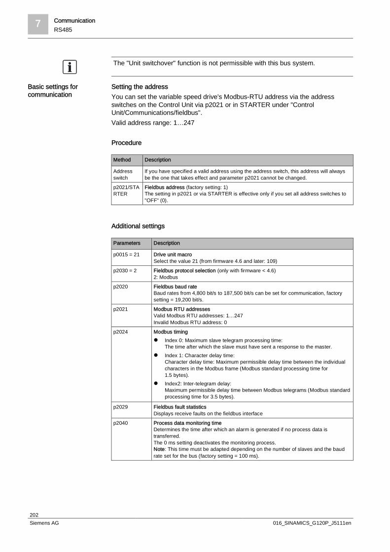
7 CommunicationRS485
202Siemens AG 016_SINAMICS_G120P_J5111en
The "Unit switchover" function is not permissible with this bus system.
Setting the addressYou can set the variable speed drive's Modbus-RTU address via the addressswitches on the Control Unit via p2021 or in STARTER under "ControlUnit/Communications/fieldbus".Valid address range: 1…247
Procedure
Method Description
Addressswitch
If you have specified a valid address using the address switch, this address will alwaysbe the one that takes effect and parameter p2021 cannot be changed.
p2021/STARTER
Fieldbus address (factory setting: 1)The setting in p2021 or via STARTER is effective only if you set all address switches to"OFF" (0).
Additional settings
Parameters Description
p0015 = 21 Drive unit macroSelect the value 21 (from firmware 4.6 and later: 109)
p2030 = 2 Fieldbus protocol selection (only with firmware < 4.6)2: Modbus
p2020 Fieldbus baud rateBaud rates from 4,800 bit/s to 187,500 bit/s can be set for communication, factorysetting = 19,200 bit/s.
p2021 Modbus RTU addressesValid Modbus RTU addresses: 1…247Invalid Modbus RTU address: 0
p2024 Modbus timingl Index 0: Maximum slave telegram processing time:
The time after which the slave must have sent a response to the master.l Index 1: Character delay time:
Character delay time: Maximum permissible delay time between the individualcharacters in the Modbus frame (Modbus standard processing time for1.5 bytes).
l Index2: Inter-telegram delay:Maximum permissible delay time between Modbus telegrams (Modbus standardprocessing time for 3.5 bytes).
p2029 Fieldbus fault statisticsDisplays receive faults on the fieldbus interface
p2040 Process data monitoring timeDetermines the time after which an alarm is generated if no process data istransferred.The 0 ms setting deactivates the monitoring process.Note: This time must be adapted depending on the number of slaves and the baudrate set for the bus (factory setting = 100 ms).
Basic settings forcommunication

Communication 7RS485
203Siemens AG 016_SINAMICS_G120P_J5111en
7.4.3 Communication via BACnet MS/TPIn BACnet, components and systems are considered to be black boxes whichcontain a number of objects. BACnet objects only define behavior outside thedevice, internal functions are not determined by BACnet.Each component is represented by a series of object types and their instances.Each BACnet device has precisely one BACnet device object. A BACnet device isuniquely identified by an NSAP (Network Service Access Point), comprising anetwork number and MAC address. The MAC (Medium Access Control) address isBACnet-specific and must not be confused with the Ethernet MAC address.
The variable speed drive receives control commands and setpoints via serviceinstructions from the control and transmits its status back to the control. Thevariable speed drive can also send telegrams automatically itself and executeservices, e.g. IAm.
l The Control Unit supports BACnet via RS485 (BACnet MS/TP)l The maximum cable length is 1,200 m (3,281 ft).
You will find the Protocol Implementation Conformance Statement (PICS) on theInternet under the following link: BACnet files:http://support.automation.siemens.com/WW/view/en/38439094
The "Unit switchover" function is not permissible with this bus system.
Setting the addressYou can set the variable speed drive's MAC ID using the address switch on theControl Unit via p2021 or in STARTER under "ControlUnit/Communications/fieldbus".Valid address range: 0 to 127 (with address 0, the variable speed drive responds toa broadcast)
w Observe the following to improve performance:
1. Assign the consecutive addresses (1, 2, 3, 4, and not 1, 4, 5, 9, etc.).
2. Restrict the max master in the G120P to the highest address assigned.
3. Max. info frame: 10
For further information, see Chapter 6 in "Basic Ethernet, TCP/IP, and BACnet onEthernet/IP" (CM110666xx).Procedure
Method Description
Addressswitch
If you have specified a valid address using the address switch, this address will alwaysbe the one that takes effect and parameter p2021 cannot be changed.
p2021/STARTER
Fieldbus address (factory setting: 1)The setting in p2021 or via STARTER is effective only if you set all address switches to"OFF" (0).
For a modified bus address to be effective, you have to switch the variable speeddrive and – if need be – any external 24 V supply off and on.
Data exchange with theclient
Communication settings
Protocol ImplementationConformance Statement
Basic settings forcommunication
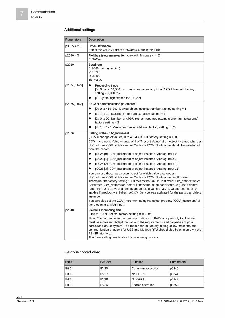
7 CommunicationRS485
204Siemens AG 016_SINAMICS_G120P_J5111en
Additional settings
Parameters Description
p0015 = 21 Drive unit macroSelect the value 21 (from firmware 4.6 and later: 110)
p2030 = 5 Fieldbus telegram selection (only with firmware < 4.6)5: BACnet
p2020 Baud rate6: 9600 (factory setting)7: 192008: 3840010: 76800
p2024[0 to 2] l Processing times[0]: 0 ms to 10,000 ms, maximum processing time (APDU timeout), factorysetting = 1,000 ms,
l [1…2]: No significance for BACnet
p2025[0 to 3] BACnet communication parameterl [0]: 0 to 4194303: Device object instance number, factory setting = 1l [1]: 1 to 10: Maximum info frames, factory setting = 1l [2]: 0 to 99: Number of APDU retries (repeated attempts after fault telegrams),
factory setting = 3l [3]: 1 to 127: Maximum master address, factory setting = 127
p2026 Setting of the COV_Increment(COV = change of values) 0 to 4194303.000, factory setting = 1000COV_Increment: Value change of the "Present Value" of an object instance where anUnConfirmedCOV_Notification or ConfirmedCOV_Notification should be transferredfrom the server.l p2026 [0]: COV_Increment of object instance "Analog Input 0"l p2026 [1]: COV_Increment of object instance "Analog Input 1"l p2026 [2]: COV_Increment of object instance "Analog Input 10"l p2026 [3]: COV_Increment of object instance "Analog Input 11"You can use these parameters to set for which value changes anUnConfirmedCOV_Notification or ConfirmedCOV_Notification result is sent.Therefore, the factory setting 1000 means that an UnConfirmedCOV_Notification orConfirmedCOV_Notification is sent if the value being considered (e.g. for a controlrange from 0 to 10 V) changes by an absolute value of ≥ 0.1. Of course, this onlyapplies if previously a SubscribeCOV_Service was activated for the particular objectinstance.You can also set the COV_Increment using the object property "COV_Increment" ofthe particular analog input.
p2040 Fieldbus monitoring time0 ms to 1,999,999 ms, factory setting = 100 msNote: The factory setting for communication with BACnet is possibly too low andmust be increased. Adapt the value to the requirements and properties of yourparticular plant or system. The reason for the factory setting of 100 ms is that thecommunication protocols for USS and Modbus RTU should also be executed via theRS485 interface.The 0 ms setting deactivates the monitoring process.
Fieldbus control word
r2090 BACnet Function Parameters
Bit 0 BV20 Command execution p0840
Bit 1 BV27 No OFF2 p0844
Bit 2 BV28 No OFF3 p0848
Bit 3 BV26 Enable operation p0852

Communication 7PROFIBUS DP
205Siemens AG 016_SINAMICS_G120P_J5111en
r2090 BACnet Function Parameters
Bit 4 BV26 Permit RFG enable p1140
Bit 5 BV26 Enable RFG p1141
Bit 6 BV26 Enable setpoint p1142
Bit 7 BV22 Acknowledge faults p2103
Bit 8 N/A Reserved -
Bit 9 N/A Reserved -
Bit 10 BV93 Master control by PLC p0854
Bit 11 BV21 Inversion direction p1113
Bit 12 N/A Reserved -
Bit 13 N/A MOP setpoint raise p1035
Bit 14 N/A MOP setpoint lower p1036
Bit 15 N/A Reserved -
The configuration workload can be reduced by leaving out values which are notrequired. In this case, the appropriate parameters must be set manually.Example: If you are not using BV93, set p0854 to 1.
7.5 PROFIBUS DPCU230P-2 DP has a SUB-D interface for connecting to PROFIBUS DP.
1) Shield, ground connection2 Not assigned3 RxD/TxD-P, receive and transmit (B/B’)4 CNTR-P, control signal5 DGND, reference potential for data (C/C’)6 VP, supply voltage7 Not assigned8 RxD/TxD-N, receive and transmit (A/A’)9 Not assigned
Check the communication settings using the following points. If you answer "Yes"to the questions, you have correctly set the communication settings and can controlthe variable speed drive via the fieldbus.l Is the variable speed drive correctly connected to the PROFIBUS?l Have you configured the communication between the variable speed drive and
the higher-level controller?l Do the bus addresses in the variable speed drive and the higher-level controller
match?l Is the same telegram set in the higher-level controller and in the variable speed
drive?l Are the signals that the variable speed drive and the controller exchange via
PROFIBUS correctly interconnected?You can find information on the individual points in the following sections.
Permissible cable lengths, routing and shielding the PROFIBUS cableInformation can be found on the Internet:
Connections on theCU230P-2 DP
Checklist forcommunication viaPROFIBUS
Connecting the variablespeed drive toPROFIBUS

7 CommunicationPROFIBUS DP
206Siemens AG 016_SINAMICS_G120P_J5111en
l Product supporthttp://www.automation.siemens.com/net/html_00/support/printkatalog.htm
l PROFIBUS user organization installation guidelineshttp://www.profibus.com/community/regional-pi-associations/germany-new/downloads/installations-richtlinien
Recommended PROFIBUS connectorsWe recommend connectors with the following order numbers for connecting thePROFIBUS cable:l 6GK1500-0FC00l 6GK1500-0EA02
Pin assignment at the variable speed drive
You must supply the Control Unit with 24 V DC at terminals 31 and 32 if you wishto maintain communication with the control system when the line voltage isswitched off.In the case of short interruptions of the 24 V voltage supply, the variable speeddrive may report the fault F without communications with the controller beinginterrupted.
To be able to configure communication between the variable speed drive andcontrol, you require the GSD description file of the variable speed drive.
Procedure
w Import the GSD of the variable speed drive into the PROFIBUS master, i.e. intoyour control system.
1. There are two ways of obtaining the GSD for your variable speed drive:– You can find the GSD for a SINAMICS variable speed drive on the Internetunderhttp://support.automation.siemens.com/WW/view/en/22339653/133100– The GSD is saved in the variable speed drive. The GSD is written to thedirectory /SIEMENS/SINAMICS/DATA/CFG if you insert a memory card intothe variable speed drive and set p0804 to 12.
2. Configure the communication between the control and the variable speed drivein your control.
You can set the variable speed drive's PROFIBUS address via the address switchon the Control Unit via p0918 or in STARTER under "ControlUnit/Communications/PROFIBUS".Valid address range: 1…125
Procedure
Method Description
Addressswitch
If you have specified a valid address with the address switches, this address will alwaysbe the one that takes effect and parameter p0918 cannot be changed.
p0918/STARTER
PROFIBUS address (factory setting: 126)Setting in p0918 or via STARTER is effective only if you set all address switches to"OFF" (0) or "ON" (1).
Configuringcommunication to thecontrol
Setting the address

Communication 7CANopen
207Siemens AG 016_SINAMICS_G120P_J5111en
For a modified bus address to be effective, you have to switch the variable speeddrive and – if need be – any external 24 V supply off and on.
During basic commissioning, you have defined a telegram for communication.In order to set a different telegram, you may need to also adapt the assignment ofthe interfaces.
Procedure
w Carry out the basic commissioning again
1. Adapt the interface assignment
2. Select the telegram.
Parameters Description
p0015 Macro drive unitConfigure the interface in basic commissioning, and select a telegram.
p0922 PROFIdrive telegram selection (factory setting for variable speed drives with PROFIBUSor PROFINET interfaces: Standard telegram 1, PZD-2/2)Settings for the transmit and receive telegram.
1:20:350:352353:354:999:
Standard telegram 1, PZD-2/2Standard telegram 20, PZD-2/6SIEMENS telegram 350, PZD-4/4SIEMENS telegram 352, PZD-6/6SIEMENS telegram 353, PZD-2/2, PKW-4/4SIEMENS telegram 354, PZD-6/6, PKW-4/4Expand telegrams and change signal interconnection
7.6 CANopenCU230P-2 CAN has an interface for CANopen.
General information about CAN can be found on the CAN Internet site under:http://www.cancia.orgThe CANdictionary under CANdownloads provides an explanation of CANterminology: http://www.can-cia.org/index.php?id=6The EDS file is the description file of the SINAMICS G120 variable speed drive forCANopen networks.If you load the EDS file into your CAN controller, you can use the objects of theDSP 402 device profile.l You can find the EDS file of the variable speed drive on the Internet under:
http://support.automation.siemens.com/WW/view/en/48351511
Select telegram
General information onCAN
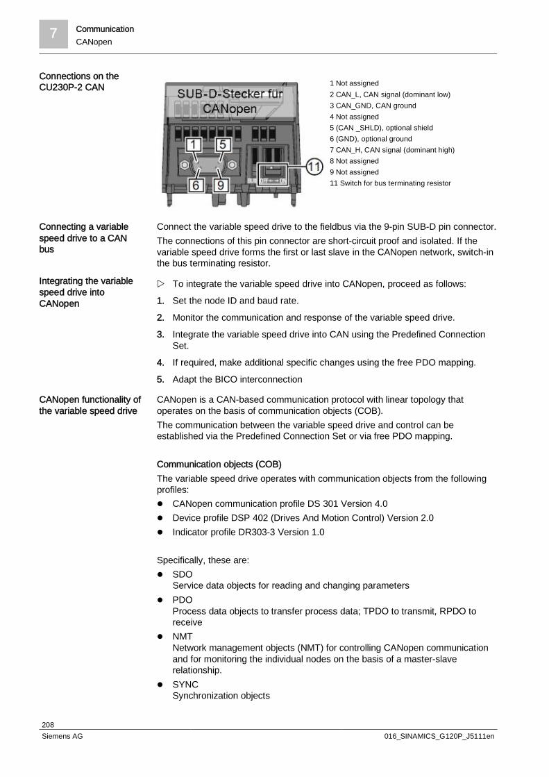
7 CommunicationCANopen
208Siemens AG 016_SINAMICS_G120P_J5111en
1 Not assigned2 CAN_L, CAN signal (dominant low)3 CAN_GND, CAN ground4 Not assigned5 (CAN _SHLD), optional shield6 (GND), optional ground7 CAN_H, CAN signal (dominant high)8 Not assigned9 Not assigned11 Switch for bus terminating resistor
Connect the variable speed drive to the fieldbus via the 9-pin SUB-D pin connector.The connections of this pin connector are short-circuit proof and isolated. If thevariable speed drive forms the first or last slave in the CANopen network, switch-inthe bus terminating resistor.
w To integrate the variable speed drive into CANopen, proceed as follows:
1. Set the node ID and baud rate.
2. Monitor the communication and response of the variable speed drive.
3. Integrate the variable speed drive into CAN using the Predefined ConnectionSet.
4. If required, make additional specific changes using the free PDO mapping.
5. Adapt the BICO interconnection
CANopen is a CAN-based communication protocol with linear topology thatoperates on the basis of communication objects (COB).The communication between the variable speed drive and control can beestablished via the Predefined Connection Set or via free PDO mapping.
Communication objects (COB)The variable speed drive operates with communication objects from the followingprofiles:l CANopen communication profile DS 301 Version 4.0l Device profile DSP 402 (Drives And Motion Control) Version 2.0l Indicator profile DR303-3 Version 1.0
Specifically, these are:l SDO
Service data objects for reading and changing parametersl PDO
Process data objects to transfer process data; TPDO to transmit, RPDO toreceive
l NMTNetwork management objects (NMT) for controlling CANopen communicationand for monitoring the individual nodes on the basis of a master-slaverelationship.
l SYNCSynchronization objects
Connections on theCU230P-2 CAN
Connecting a variablespeed drive to a CANbus
Integrating the variablespeed drive intoCANopen
CANopen functionality ofthe variable speed drive
Communication 7PROFINET
209Siemens AG 016_SINAMICS_G120P_J5111en
l EMCYTime stamp and fault messages
COB IDA communication object includes data – which is transferred – and an 11-bit COBID, which uniquely identifies it. The priority when executing the communicationobjects is controlled using the COB ID. The communication object with the lowestCOB ID has the highest priority.
COB ID for individual communication objectsYou will find the specifications for the COB IDs of the individual communicationobjects below:l COB IDNMT = 0 cannot be changedl COB IDSYNC = free – in most cases, this is preassigned with 80 hexl COB IDEMCY = free – in most cases COB IDSYNC + node ID = COB IDEMCYl COB IDTPDO = free in free PDO mappingl COB IDRPDO = free in free PDO mappingl COB IDTSDO = 580 + node IDl COB IDRSDO = 600 + node IDl COB IDNode Guarding/Heartbeat = 700 + node ID
Setting the node ID and baud rateIn the variable speed drive, you must set the node ID and the baud rate to permitcommunication.
Changes made to the node ID or baud rate only become effective after switchingoff and on again. It is particularly important that any external 24 V supply isswitched off.Note that before turning off, you must save the changes using RAM -> ROM.The currently active node ID is displayed in parameter r8621.
You can define the node ID either using the address switch on the CU viaparameter p8620 or in STARTER in the screen form under"Control Unit/Communications/CAN" under the CAN interface tab.Valid address range: 1…126When a valid node ID has been set using the address switches, then this is alwayseffective and p8620 cannot be changed.If you set all address switches to "OFF" (0) or "ON" (1), specify the node ID viap8620 or STARTER.
Setting the data transmission rateYou can set the transmission rate in the range from 10 kbit/s to 1 Mbit/s usingparameter p8622 or in the STARTER screen form "ControlUnit/Communication/CAN" under the CAN interface tab.
7.7 PROFINETCU230P-2 PN has an RJ45 interface for connecting to PROFINET
CommissioningCANopen

7 CommunicationPROFINET
210Siemens AG 016_SINAMICS_G120P_J5111en
1 RX+, receive data +2 RX-, receive data -3 TX+. transmit data +4 Not assigned5 Not assigned6 TX-, transmit data -7 Not assigned8 Not assigned
The Control Unit provides the following functions:l IRT
without isochronous model MRP
Media redundancy, not bumpless with 200 msPrecondition: Ring topology
l MRPDMedia redundancy, bumplessPrecondition: IRT and the ring topology created in the control
l Diagnostic interruptAccording to error classes specified in the PROFIdrive profile
l Device replacement without removable mediumPrecondition: Topology created in the control
The Control Units have two RJ45 sockets, which you can use to implement a linetopology. You can implement all topologies by using switches.
General information on PROFINET can be found on the Internet under IndustrialCommunication:http://www.automation.siemens.com/mcms/automation/de/industriellekommunikation/profinet/Seiten/Default.aspxThe configuration of the functions is described in the PROFINET systemdescription manual.http://support.automation.siemens.com/WW/view/en/19292127
Check the communication settings using the following points. If you answer "Yes"to the questions, you have correctly set the communication settings and can controlthe variable speed drive via the fieldbus.l Is the variable speed drive correctly connected to the PROFINET?l Do the IP address and device name in the variable speed drive and controller
match?l Is the same telegram set in the variable speed drive as in the higher-level
controller?l Are the signals that the variable speed drive and the controller exchange via
PROFINET correctly interconnected?
Connect the variable speed drive (IO device) and your PG/PC (IO supervisor) viaPROFINET cables with the control.
Recommended PROFINET connectors and pin assignment
Connections on theCU230P-2 PN
Functions
Additional information
Checklist forcommunication viaPROFINET
Connecting the variablespeed drive toPROFINET

Communication 7PROFINET
211Siemens AG 016_SINAMICS_G120P_J5111en
We recommend the following connector with order number: 6GK1901-1BB10-2Ax0for connecting the PROFINET cable.Instructions for assembling the SIMATIC NET Industrial Ethernet FastConnectRF45 Plug 180 can be found on the Internet under product information "Assemblyinstructions for SIMATIC NET Industrial Ethernet FastConnect RJ45 Plug" at:http://support.automation.siemens.com/WW/view/en/37217116/133300
Laying and shielding the PROFINET cableInformation can be found on the Internet: PROFIBUS user organization installationguidelines at:http://www.profibus.com/community/regional-pi-associations/germanynew/downloads/installations-richtlinien/
In order to establish communication between the variable speed drive and controlsystem via PROFINET, load the device file of the variable speed drive "GSDML"into your control.You can then configure the communication.
Procedure
w Import the GSDML of the variable speed drive into the PROFINET controller,i.e. into your control system.You have two options for obtaining the GSDML for your variable speed drive:
1. You can find the GDSML for the SINAMICS variable speed drive on theInternet at:http://support.automation.siemens.com/WW/view/en/22339653/133100
2. The GSDML is saved in the variable speed drive. The GSDML is written to thedirectory /SIEMENS/SINAMICS/DATA/CFG if you insert a memory card intothe variable speed drive and set p0804 to 12.
3. Configure the communication between the control and the variable speed drivein your control.
During basic commissioning, you have defined a telegram for communication.In order to set a different telegram, you may need to also adapt the assignment ofthe interfaces.
Procedure
w Carry out the basic commissioning again
1. Adapt the interface assignment
2. Select the telegram.
Parameters Description
p0015 Macro drive unitConfigure the interface in basic commissioning, and select a telegram.
p0922 PROFIdrive telegram selection (factory setting for variable speed drives with PROFIBUSor PROFINET interfaces: Standard telegram 1, PZD-2/2)Settings for the transmit and receive telegram.
1:20:350:352353:
Standard telegram 1, PZD-2/2Standard telegram 20, PZD-2/6SIEMENS telegram 350, PZD-4/4SIEMENS telegram 352, PZD-6/6SIEMENS telegram 353, PZD-2/2, PKW-4/4
Configuringcommunication to thecontrol
Select telegram

7 CommunicationPROFINET
212Siemens AG 016_SINAMICS_G120P_J5111en
Parameters Description
354:999:
SIEMENS telegram 354, PZD-6/6, PKW-4/4Expand telegrams and change signal interconnection
The variable speed drive allows you to transmit fault and alarmmessages/diagnostic messages to the control according to the PROFIdrive errorclasses.The functionality must be selected in the control and activated by a ramp-up.You can output the messages directly on an HMI panel via the control.
Activating diagnostics viathe control

Applications 8Universal application
213Siemens AG 016_SINAMICS_G120P_J5111en
8 Applications
8.1 Universal applicationl Macro 101 "Universal application"l Setpoint via a 0 to 10 V signall Analog setpoint can be overridden with 3 fixed speedsl Flying restart and automatic restart are activatedl Essential Service Mode (in the event of fire) with a
fixed setpointl The fault code is generated via digital output 0l The operating display is generated via digital output 2Note:In the case of the Essential Service Mode, the customercan no longer lodge any claims for warranty. EssentialService Mode and the faults which arise during this modeare logged in a password-protected memory and can beread by the repair center.
L1L2L3PE
L1 L2 L3
u v w
9
5
M3
6
7
8
16
17
14
15
AIN 0+
AIN 0-
PTC A
PTC B
DIN 0
DIN 1
DIN 2
DIN 3
DIN 4
DIN 5
3
40 - 10 V
P24V
25
24
23
22
21
20
19
18
AOUT 0+
AOUT 0-
AOUT 1+
AOUT 1-
Optional
DO 0
DO 1
DO 2
External Fault
ESM Activation
Fix speed 1
Fix speed 2
Fix speed 3
ControlSystem
28
69GND
DI COM
12
13
26
27
ON / OFF
Fuses
Fault
Speed (0..20mA)
Output current (0..20mA)
Enable secondVSD
Operation
Parameters Value Description
p731 r52.2 Signal source for terminal DO 1
p756[0] 0 Unipolar voltage input (0 to 10 V)
p840[0] r20047.0 ON/OFF (OFF1)
p1000[0] 32 Speed setpoint selection
p1001[0] 800 rpm Fixed speed setpoint 1
p1002[0] 1000 rpm Fixed speed setpoint 2
p1003[0] 1,200 rpm Fixed speed setpoint 3
p1015[0] 1,500 rpm Fixed speed setpoint 15
p1020[0] r722.3 Fixed speed setpoint selection bit 0
p1021[0] r722.4 Fixed speed setpoint selection bit 1
p1022[0] r722.5 Fixed speed setpoint selection bit 2
p1071[0] r20220 Main setpoint scaling
p1113[0] 0 Setpoint inversion
p1200[0] 1 Flying restart always active (start in setpoint direction)
p1210 26 Acknowledging all faults and restarting for an ON command
p2103[0] 0 Acknowledge faults
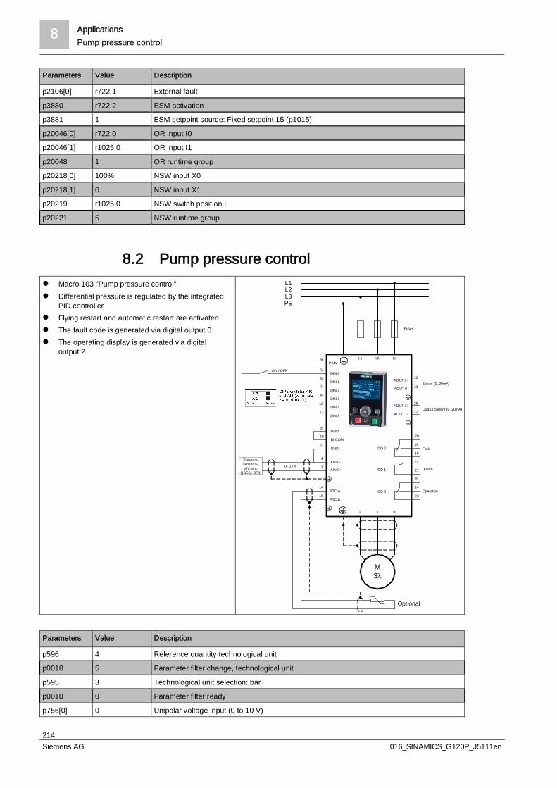
8 ApplicationsPump pressure control
214Siemens AG 016_SINAMICS_G120P_J5111en
Parameters Value Description
p2106[0] r722.1 External fault
p3880 r722.2 ESM activation
p3881 1 ESM setpoint source: Fixed setpoint 15 (p1015)
p20046[0] r722.0 OR input I0
p20046[1] r1025.0 OR input I1
p20048 1 OR runtime group
p20218[0] 100% NSW input X0
p20218[1] 0 NSW input X1
p20219 r1025.0 NSW switch position I
p20221 5 NSW runtime group
8.2 Pump pressure controll Macro 103 "Pump pressure control"l Differential pressure is regulated by the integrated
PID controllerl Flying restart and automatic restart are activatedl The fault code is generated via digital output 0l The operating display is generated via digital
output 2
L1L2L3PE
L1 L2 L3
u v w
9
5
M3l
6
7
8
16
17
14
15
AIN 0+
AIN 0-
PTC A
PTC B
DIN 0
DIN 1
DIN 2
DIN 3
DIN 4
DIN 5
3
4
0 - 10 V
P24V
25
24
23
22
21
20
19
18
AOUT 0+
AOUT 0-
AOUT 1+
AOUT 1-
Optional
DO 0
DO 1
DO 2
Pressuresensor 0-10V, e.g.
QBE64-DP4
28
69GND
DI COM2
GND
12
13
26
27
Fuses
ON / OFF
Fault
Alarm
Operation
Speed (0..20mA)
Output current (0..20mA)
Parameters Value Description
p596 4 Reference quantity technological unit
p0010 5 Parameter filter change, technological unit
p595 3 Technological unit selection: bar
p0010 0 Parameter filter ready
p756[0] 0 Unipolar voltage input (0 to 10 V)
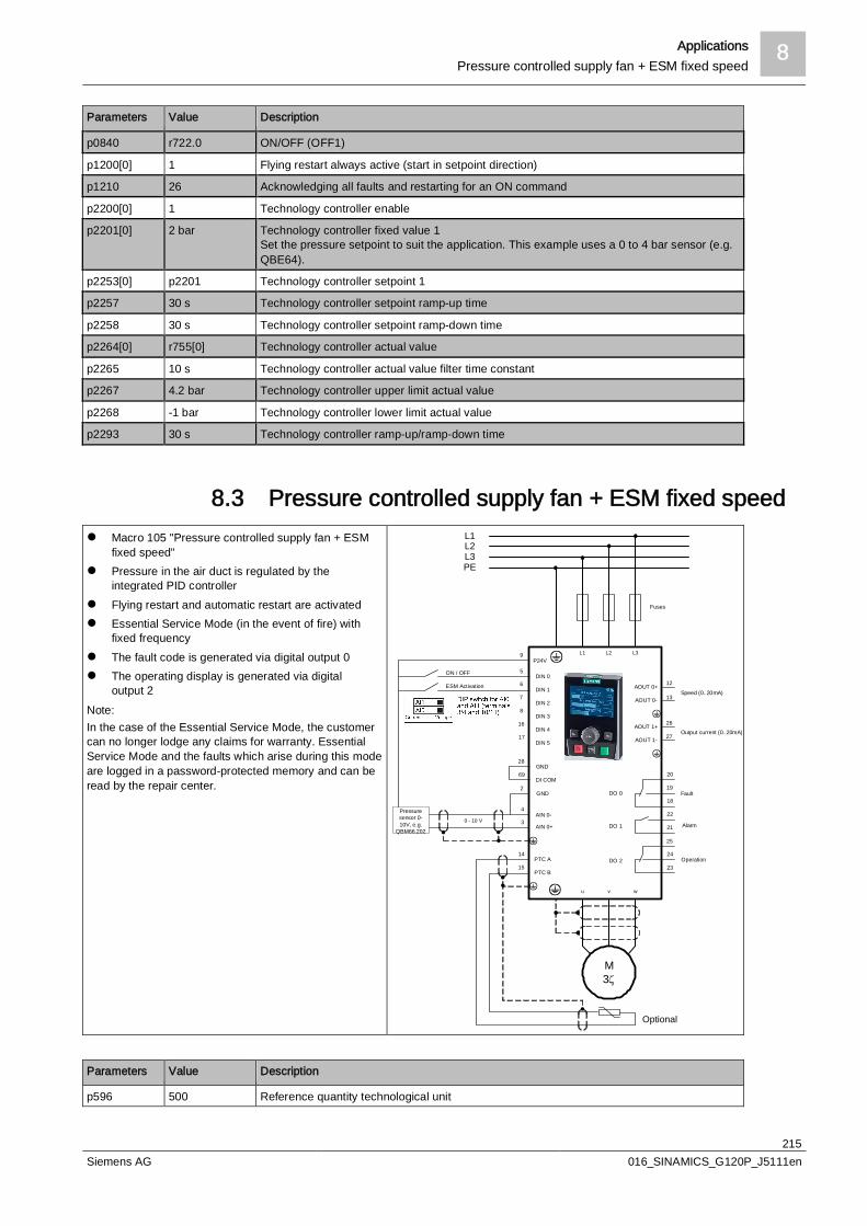
Applications 8Pressure controlled supply fan + ESM fixed speed
215Siemens AG 016_SINAMICS_G120P_J5111en
Parameters Value Description
p0840 r722.0 ON/OFF (OFF1)
p1200[0] 1 Flying restart always active (start in setpoint direction)
p1210 26 Acknowledging all faults and restarting for an ON command
p2200[0] 1 Technology controller enable
p2201[0] 2 bar Technology controller fixed value 1Set the pressure setpoint to suit the application. This example uses a 0 to 4 bar sensor (e.g.QBE64).
p2253[0] p2201 Technology controller setpoint 1
p2257 30 s Technology controller setpoint ramp-up time
p2258 30 s Technology controller setpoint ramp-down time
p2264[0] r755[0] Technology controller actual value
p2265 10 s Technology controller actual value filter time constant
p2267 4.2 bar Technology controller upper limit actual value
p2268 -1 bar Technology controller lower limit actual value
p2293 30 s Technology controller ramp-up/ramp-down time
8.3 Pressure controlled supply fan + ESM fixed speedl Macro 105 "Pressure controlled supply fan + ESM
fixed speed"l Pressure in the air duct is regulated by the
integrated PID controllerl Flying restart and automatic restart are activatedl Essential Service Mode (in the event of fire) with
fixed frequencyl The fault code is generated via digital output 0l The operating display is generated via digital
output 2Note:In the case of the Essential Service Mode, the customercan no longer lodge any claims for warranty. EssentialService Mode and the faults which arise during this modeare logged in a password-protected memory and can beread by the repair center.
L1L2L3PE
L1 L2 L3
u v w
9
5
M3z
6
7
8
16
17
14
15
AIN 0+
AIN 0-
PTC A
PTC B
DIN 0
DIN 1
DIN 2
DIN 3
DIN 4
DIN 5
3
4
0 - 10 V
P24V
25
24
23
22
21
20
19
18
AOUT 0+
AOUT 0-
AOUT 1+
AOUT 1-
Optional
DO 0
DO 1
DO 2
Pressuresensor 0-10V, e.g.
QBM66.202
28
69GND
DI COM
ESM Activation
2GND
12
13
26
27
Fuses
ON / OFF
Fault
Alarm
Operation
Speed (0..20mA)
Output current (0..20mA)
Parameters Value Description
p596 500 Reference quantity technological unit

8 ApplicationsPressure controlled supply fan + ESM fixed speed
216Siemens AG 016_SINAMICS_G120P_J5111en
Parameters Value Description
p0010 5 Parameter filter change, technological unit
p595 5 Technological unit selection: Pa
p0010 0 Parameter filter ready
p756[0] 0 Unipolar voltage input (0 to 10 V)
p0840 r722.0 ON/OFF (OFF1)
p1015[0] 1,350 rpm Fixed speed setpoint 15
p1113[0] 0 Setpoint inversion
p1200[0] 1 Flying restart always active (start in setpoint direction)
p1210 26 Acknowledging all faults and restarting for an ON command
p2200[0] 1 Technology controller enable
p2201[0] 200 Pa Technology controller fixed value 1
p2253[0] p2201 Technology controller setpoint 1
p2257 30 s Technology controller setpoint ramp-up time
p2258 30 s Technology controller setpoint ramp-down time
p2264[0] r755[0] Technology controller actual value
p2265 10 s Technology controller actual value filter time constant
p2267 600 Pa Technology controller upper limit actual value
p2268 -50 Pa Technology controller lower limit actual value
p2293 30 s Technology controller ramp-up/ramp-down time
p3880 r722.1 ESM activation
p3881 1 ESM setpoint source: Fixed setpoint 15 (p1015)
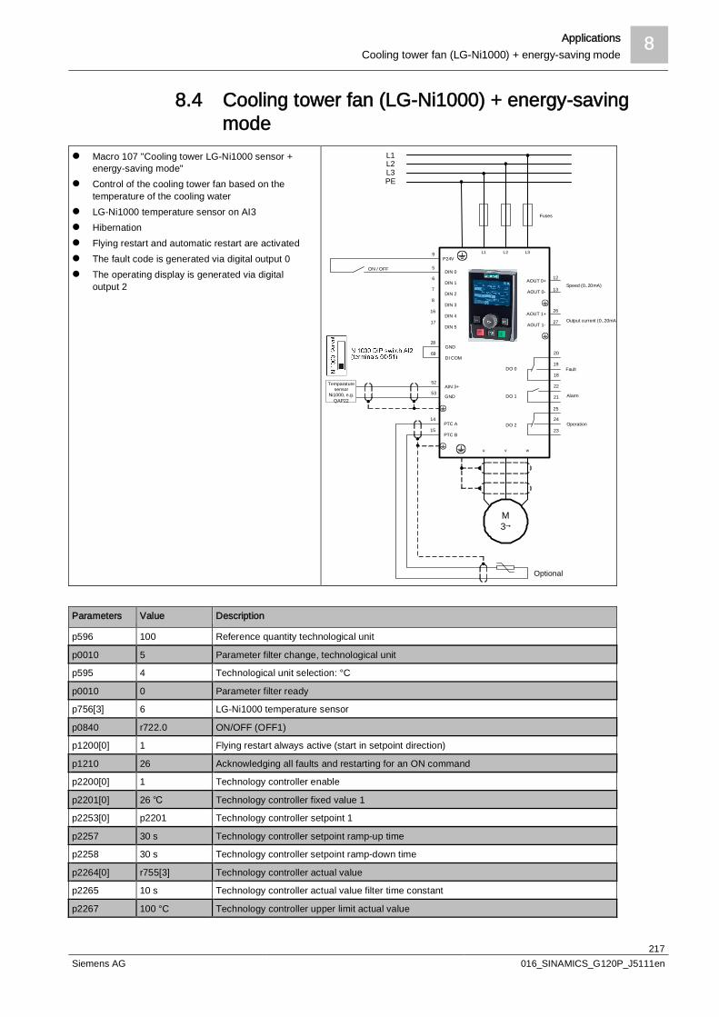
Applications 8Cooling tower fan (LG-Ni1000) + energy-saving mode
217Siemens AG 016_SINAMICS_G120P_J5111en
8.4 Cooling tower fan (LG-Ni1000) + energy-savingmode
l Macro 107 "Cooling tower LG-Ni1000 sensor +energy-saving mode"
l Control of the cooling tower fan based on thetemperature of the cooling water
l LG-Ni1000 temperature sensor on AI3l Hibernationl Flying restart and automatic restart are activatedl The fault code is generated via digital output 0l The operating display is generated via digital
output 2
L1L2L3PE
L1 L2 L3
u v w
9
5
M3
6
7
8
16
17
14
15
GND
AIN 3+
PTC A
PTC B
DIN 0
DIN 1
DIN 2
DIN 3
DIN 4
DIN 5
53
52
P24V
25
24
23
22
21
20
19
18
AOUT 0+
AOUT 0-
AOUT 1+
AOUT 1-
Optional
DO 0
DO 1
DO 2
Temparaturesensor
Ni1000, e.g.QAP22
28
69GND
DI COM
12
13
26
27
Fuses
ON / OFF
Fault
Alarm
Operation
Speed (0..20mA)
Output current (0..20mA)
Parameters Value Description
p596 100 Reference quantity technological unit
p0010 5 Parameter filter change, technological unit
p595 4 Technological unit selection: °C
p0010 0 Parameter filter ready
p756[3] 6 LG-Ni1000 temperature sensor
p0840 r722.0 ON/OFF (OFF1)
p1200[0] 1 Flying restart always active (start in setpoint direction)
p1210 26 Acknowledging all faults and restarting for an ON command
p2200[0] 1 Technology controller enable
p2201[0] 26 Technology controller fixed value 1
p2253[0] p2201 Technology controller setpoint 1
p2257 30 s Technology controller setpoint ramp-up time
p2258 30 s Technology controller setpoint ramp-down time
p2264[0] r755[3] Technology controller actual value
p2265 10 s Technology controller actual value filter time constant
p2267 100 °C Technology controller upper limit actual value
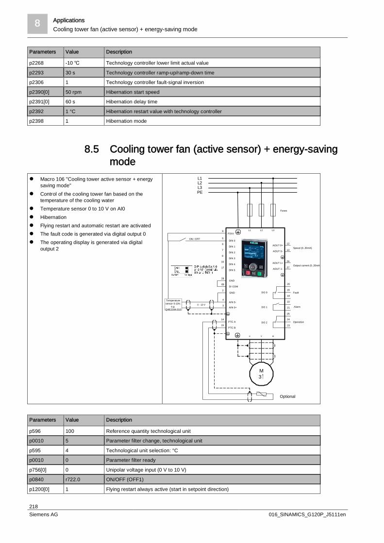
8 ApplicationsCooling tower fan (active sensor) + energy-saving mode
218Siemens AG 016_SINAMICS_G120P_J5111en
Parameters Value Description
p2268 -10 Technology controller lower limit actual value
p2293 30 s Technology controller ramp-up/ramp-down time
p2306 1 Technology controller fault-signal inversion
p2390[0] 50 rpm Hibernation start speed
p2391[0] 60 s Hibernation delay time
p2392 1 °C Hibernation restart value with technology controller
p2398 1 Hibernation mode
8.5 Cooling tower fan (active sensor) + energy-savingmode
l Macro 106 "Cooling tower active sensor + energysaving mode"
l Control of the cooling tower fan based on thetemperature of the cooling water
l Temperature sensor 0 to 10 V on AI0l Hibernationl Flying restart and automatic restart are activatedl The fault code is generated via digital output 0l The operating display is generated via digital
output 2
L1L2L3PE
L1 L2 L3
u v w
9
5
M3
6
7
8
16
17
14
15PTC A
PTC B
DIN 0
DIN 1
DIN 2
DIN 3
DIN 4
DIN 5
P24V
25
24
23
22
21
20
19
18
AOUT 0+
AOUT 0-
AOUT 1+
AOUT 1-
Optional
DO 0
DO 1
DO 2
28
69GND
DI COM
AIN 0+
AIN 0-3
4
0 - 10 V
Temperaturesensor 0-10V,
e.g.QAE2164.010
2GND
12
13
26
27
Fuses
ON / OFF
Fault
Alarm
Operation
Speed (0..20mA)
Output current (0..20mA)
Parameters Value Description
p596 100 Reference quantity technological unit
p0010 5 Parameter filter change, technological unit
p595 4 Technological unit selection: °C
p0010 0 Parameter filter ready
p756[0] 0 Unipolar voltage input (0 V to 10 V)
p0840 r722.0 ON/OFF (OFF1)
p1200[0] 1 Flying restart always active (start in setpoint direction)
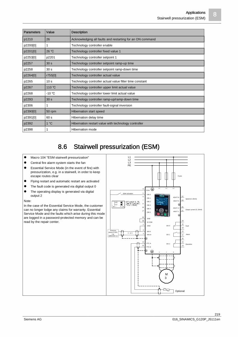
Applications 8Stairwell pressurization (ESM)
219Siemens AG 016_SINAMICS_G120P_J5111en
Parameters Value Description
p1210 26 Acknowledging all faults and restarting for an ON command
p2200[0] 1 Technology controller enable
p2201[0] 26 Technology controller fixed value 1
p2253[0] p2201 Technology controller setpoint 1
p2257 30 s Technology controller setpoint ramp-up time
p2258 30 s Technology controller setpoint ramp-down time
p2264[0] r755[0] Technology controller actual value
p2265 10 s Technology controller actual value filter time constant
p2267 110 Technology controller upper limit actual value
p2268 -10 Technology controller lower limit actual value
p2293 30 s Technology controller ramp-up/ramp-down time
p2306 1 Technology controller fault-signal inversion
p2390[0] 50 rpm Hibernation start speed
p2391[0] 60 s Hibernation delay time
p2392 1 °C Hibernation restart value with technology controller
p2398 1 Hibernation mode
8.6 Stairwell pressurization (ESM)l Macro 104 "ESM stairwell pressurization"l Central fire alarm system starts the fanl Essential Service Mode (in the event of fire) with
pressurization, e.g. in a stairwell, in order to keepescape routes clear
l Flying restart and automatic restart are activatedl The fault code is generated via digital output 0l The operating display is generated via digital
output 2Note:In the case of the Essential Service Mode, the customercan no longer lodge any claims for warranty. EssentialService Mode and the faults which arise during this modeare logged in a password-protected memory and can beread by the repair center.
L1L2L3PE
L1 L2 L3
u v w
9
5
M3
6
7
8
16
17
14
15
AIN 0+
AIN 0-
PTC A
PTC B
DIN 0
DIN 1
DIN 2
DIN 3
DIN 4
DIN 5
3
4
0 - 10 V
P24V
25
24
23
22
21
20
19
18
AOUT 0+
AOUT 0-
AOUT 1+
AOUT 1-
Optional
DO 0
DO 1
DO 2
ESM Activation
Pressuresensor 0-10V,
e.g.QBM2030-1U
28
69GND
DI COM2
GND
12
13
26
27
Fuses
Fault
Alarm
Operation
Speed (0..20mA)
Output current (0..20mA)
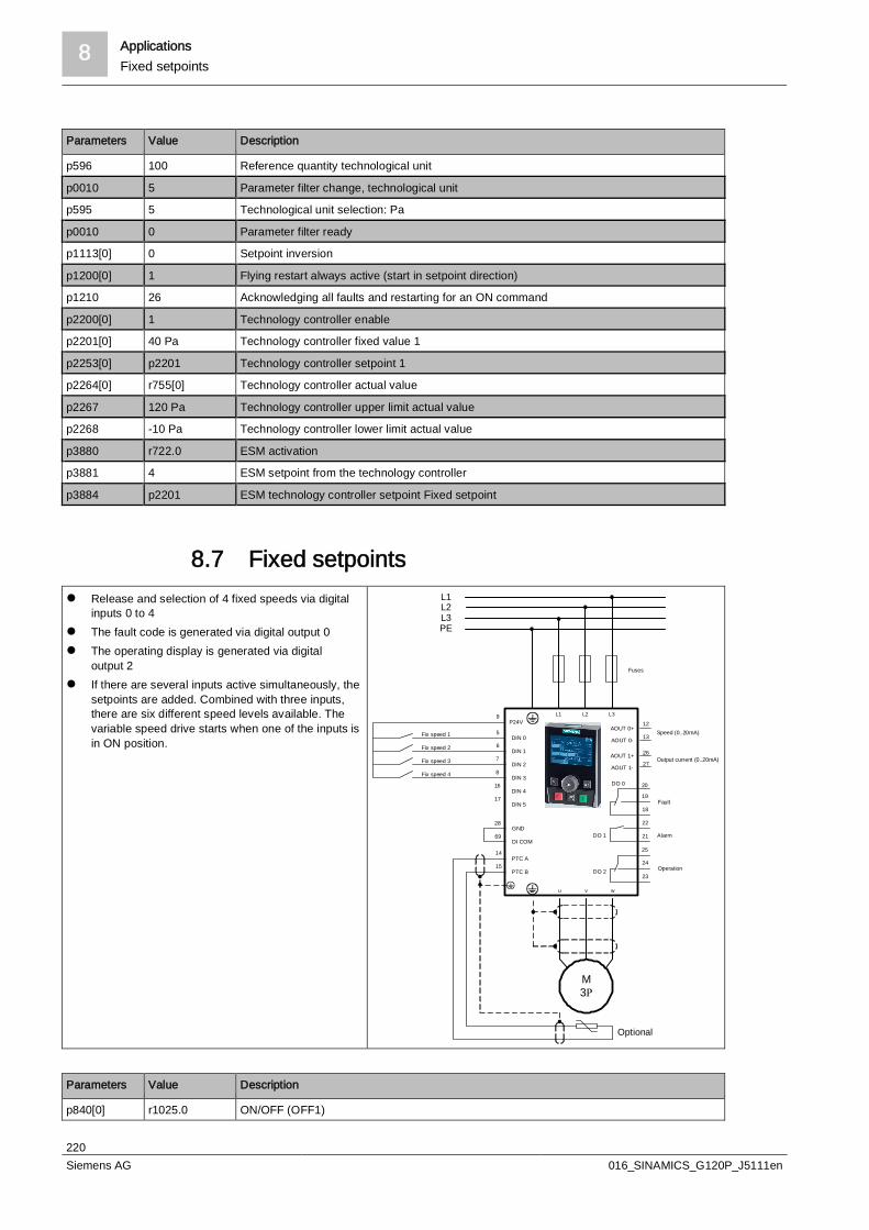
8 ApplicationsFixed setpoints
220Siemens AG 016_SINAMICS_G120P_J5111en
Parameters Value Description
p596 100 Reference quantity technological unit
p0010 5 Parameter filter change, technological unit
p595 5 Technological unit selection: Pa
p0010 0 Parameter filter ready
p1113[0] 0 Setpoint inversion
p1200[0] 1 Flying restart always active (start in setpoint direction)
p1210 26 Acknowledging all faults and restarting for an ON command
p2200[0] 1 Technology controller enable
p2201[0] 40 Pa Technology controller fixed value 1
p2253[0] p2201 Technology controller setpoint 1
p2264[0] r755[0] Technology controller actual value
p2267 120 Pa Technology controller upper limit actual value
p2268 -10 Pa Technology controller lower limit actual value
p3880 r722.0 ESM activation
p3881 4 ESM setpoint from the technology controller
p3884 p2201 ESM technology controller setpoint Fixed setpoint
8.7 Fixed setpointsl Release and selection of 4 fixed speeds via digital
inputs 0 to 4l The fault code is generated via digital output 0l The operating display is generated via digital
output 2l If there are several inputs active simultaneously, the
setpoints are added. Combined with three inputs,there are six different speed levels available. Thevariable speed drive starts when one of the inputs isin ON position.
L1L2L3PE
L1 L2 L3
u v w
9
5
M3R
6
7
8
16
17
14
15PTC A
PTC B
DIN 0
DIN 1
DIN 2
DIN 3
DIN 4
DIN 5
P24V
25
24
23
22
21
20
19
18
Optional
DO 0
DO 1
DO 2
Fix speed 1
Fix speed 2
Fix speed 3
28
69GND
DI COM
Fix speed 4
AOUT 0+
AOUT 0-
AOUT 1+
AOUT 1-
12
13
26
27
Fuses
Fault
Alarm
Operation
Speed (0..20mA)
Output current (0..20mA)
Parameters Value Description
p840[0] r1025.0 ON/OFF (OFF1)

Applications 8CO2 sensor, 2 PID setpoints
221Siemens AG 016_SINAMICS_G120P_J5111en
Parameters Value Description
p1000[0] 3 Speed setpoint selection: Fixed speed
p1001[0] 300 rpm Fixed speed setpoint 1
p1002[0] 600 rpm Fixed speed setpoint 2
p1003[0] 900 rpm Fixed speed setpoint 3
p1004[0] 1,200 rpm Fixed speed setpoint 4
p1020[0] r722.0 BI: Fixed speed setpoint selection bit 0
p1021[0] r722.1 BI: Fixed speed setpoint selection bit 1
p1022[0] r722.2 BI: Fixed speed setpoint selection bit 2
p1023[0] r722.3 BI: Fixed speed setpoint selection bit 3
p1113[0] 0 BI: Setpoint inversion
p2103[0] 0 BI: 1. Acknowledge faults
8.8 CO2 sensor, 2 PID setpointsl ON/OFF and PID setpoint selection via DI0 or DI2l Set the fixed setpoint (50% corresponding to the
CO2 equivalent 1,000 ppm)l External alarm at DI1. The fan is stopped.l The fault code is generated via digital output 0l The operating display is generated via digital
output 2l If DI0 and DI2 are active simultaneously, the
setpoints are added. The variable speed drive startswhen one of the inputs is in ON position.
L1L2L3PE
L1 L2 L3
u v w
9
5
M3n
6
7
8
16
17
14
15
AIN 0+
AIN 0-
PTC A
PTC B
DIN 0
DIN 1
DIN 2
DIN 3
DIN 4
DIN 5
3
4
0 - 10 V
P24V
25
24
23
22
21
20
19
18
AOUT 0+
AOUT 0-
AOUT 1+
AOUT 1-
Optional
DO 0
DO 1
DO 2
Air quality sensor0-10V, e.g.QPM2100
28
69GND
DI COM2
GND
External fault
ON / OFF Setpoint 2
12
13
26
27
Fuses
ON / OFF Setpoint 1
Fault
Alarm
Operation
Speed (0..20mA)
Output current (0..20mA)
Parameters Value Description
p756[0] 0 Unipolar voltage input (0 to 10 V)
p840[0] r2225.0 ON/OFF (OFF1)
p1113[0] 0 Setpoint inversion
p2103[0] 0 BI: 1. Acknowledge faults
p2106[0] r722.1 External fault

8 ApplicationsCO2 sensor, 2 PID setpoints
222Siemens AG 016_SINAMICS_G120P_J5111en
Parameters Value Description
p2200[0] 1 Technology controller enable
p2201[0] 50 Technology controller fixed value 1
p2203[0] 10 Technology controller fixed value 3
p2220[0] r722.0 BI: Technology controller fixed value selection bit 0
p2222[0] r722.2 BI: Technology controller fixed value selection bit 2
p2253[0] r2224 Technology controller setpoint 1
p2264[0] r755[0] Technology controller actual value
p2267 120% Technology controller upper limit actual value
p2268 -10% Technology controller lower limit actual value
p2306 1 Technology controller fault-signal inversion
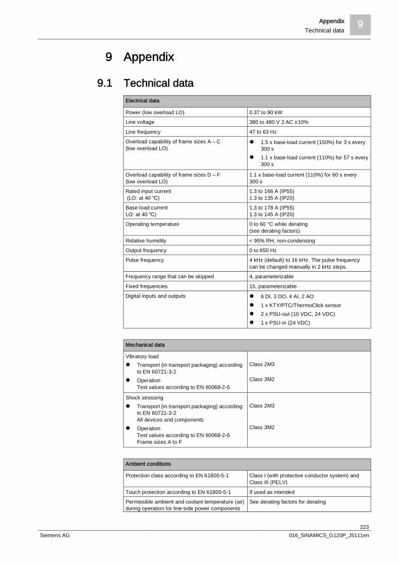
Appendix 9Technical data
223Siemens AG 016_SINAMICS_G120P_J5111en
9 Appendix
9.1 Technical dataElectrical data
Power (low overload LO) 0.37 to 90 kW
Line voltage 380 to 480 V 3 AC ±10%
Line frequency 47 to 63 Hz
Overload capability of frame sizes A – C(low overload LO)
l 1.5 x base-load current (150%) for 3 s every300 s
l 1.1 x base-load current (110%) for 57 s every300 s
Overload capability of frame sizes D – F(low overload LO)
1.1 x base-load current (110%) for 60 s every300 s
Rated input current (LO: at 40 )
1.3 to 166 A (IP55)1.3 to 135 A (IP20)
Base-load currentLO: at 40 )
1.3 to 178 A (IP55)1.3 to 145 A (IP20)
Operating temperature 0 to 60 °C while derating(see derating factors)
Relative humidity < 95% RH, non-condensing
Output frequency 0 to 650 Hz
Pulse frequency 4 kHz (default) to 16 kHz. The pulse frequencycan be changed manually in 2 kHz steps.
Frequency range that can be skipped 4, parameterizable
Fixed frequencies 15, parameterizable
Digital inputs and outputs l 6 DI, 3 DO, 4 AI, 2 AOl 1 x KTY/PTC/ThermoClick sensorl 2 x PSU-out (10 VDC, 24 VDC)l 1 x PSU-in (24 VDC)
Mechanical data
Vibratory loadl Transport (in transport packaging) according
to EN 60721-3-2l Operation
Test values according to EN 60068-2-6
Class 2M3
Class 3M2
Shock stressingl Transport (in transport packaging) according
to EN 60721-3-2All devices and components
l OperationTest values according to EN 60068-2-6Frame sizes A to F
Class 2M3
Class 3M2
Ambient conditions
Protection class according to EN 61800-5-1 Class I (with protective conductor system) andClass III (PELV)
Touch protection according to EN 61800-5-1 If used as intended
Permissible ambient and coolant temperature (air)during operation for line-side power components
See derating factors for derating

9 AppendixTechnical data
224Siemens AG 016_SINAMICS_G120P_J5111en
Ambient conditions
and Power Modulesl Low overload
(low overload LO)
l High overload(high overload HO)
0 to 40 °C (32 to 104 °F) without derating> 40 to 60 (104 to 160 °F) with derating
0 to 50 (32 to 122 °F) without derating> 50 to 60 (122 to 160 °F) with derating
Permissible ambient and coolant temperature (air)during operation for Control Units andsupplementary system components
l With CU230P-2: 0 to 60 °C (32 to 140 °F)l With IOP-2: 0 to 50 °C (32 to 122 °F)l With BOP-2: 0 to 50 °C (32 to 122 °F)l With blanking cover: 0 to 60 °C (32 to 140 °F)l Up to 2000 m above sea level
Climatic ambient conditionsl Storage (in transport packaging) according to
EN 60721-3-1l Transport (in transport packaging) according
to EN 60721-3-2
l Operation acc. to EN 60721-3-3
Class 1K3Temperature -25 to 55 (-13…131 °F)Class 2K4Temperature -40 to 70 (104…158 °F), max.humidity 95% at 40 °C (104 °F)Class 3K3Condensation, splashwater, and ice formationnot permitted(EN 60204, Part 1)
Environmental class/harmful chemicalsubstances:l Storage (in transport packaging) according to
EN 60721-3-1l Transport (in transport packaging) according
to EN 60721-3-2l Operation acc. to EN 60721-3-3
Class 1C2
Class 2C2
Class 3C2
Organic/biological influences:l Storage (in transport packaging) according to
EN 60721-3-1l Transport (in transport packaging) according
to EN 60721-3-2l Operation acc. to EN 60721-3-3
Class 1B1
Class 2B1
Class 3B1
Degree of pollution according to EN 61800-5-1 2
Standards and Directives
Standards conformance UL, CE, c-tick
CE marking According to Low-Voltage Directive 2006/95/EC
EMC Directive acc. to EN 61800-3: 2004l Frame sizes FSA to FSF with integrated line
filter class Al Frame sizes FSA to FSF with integrated or
external line filter class B
With shielded motor cable up to 25 m:Category C2, corresponds to Class A acc. toEN 55011Category C1, corresponds to class B acc. toEN 55011 for conducted interference emission
Variable-speed electrical power drive systems –part 3: EMC product standard including specifictest methods
EN 61800-3: 2004
Electromagnetic compatibility – part 3-12: Limitvalues for temperature monitoring
EN 61000-3-12: 2011 (RSCE > 250)
UL approval for frame sizes FSD to FSF will be available soon.

Appendix 9Technical data
225Siemens AG 016_SINAMICS_G120P_J5111en

Index entries
226Siemens AG 016_SINAMICS_G120P_J5111en
Index entriesNumerics87 Hz characteristic, 24, 47, 49
AActivating free blocks, 195Activation sequence, 147Ambient conditions, 44, 57Analog inputs, 103Analog outputs, 105Automatic restart, 122
BBACnet, 203BACnet MS/TP, 198BICO, 100, 152, 191Binector inputs (BI), 101Binector outputs (BO), 102Blanking cover, 25, 30Boost, 154Boost), 113BOP-2, 25, 29, 30, 198Braking function, 115Burst, 63Bus protocol, 198Bypass, 157
Essential Service Mode, 184Bypassing the variable speed drive, 157
CCable
Motor connection, 85Signals and data, 87
cableSupply, 85
Cable cross-sections, 86Cable lengths, 86Cable routing, 78Calculating the enclosure size, 33CANopen, 207CAN-open, 198Capacitive coupling, 64Cascade control, 146Category C1, C2, C3, 58CE conformity, 14
Characteristics, 112Chip temperature, 186Circuit breaker, 90Class A1, 56, 58Class B, 56, 58Class A2, 57Compactors, 45Compressors, 45Conductor cross-sections, 86Connections, 39Connector inputs (CI), 105Connector outputs (CO), 107Control cabinet, 73, 74, 90
Cable routing, 76coupling
Capacitive, 64Direct, 64Inductive, 65Radiative, 66
Coupling path, 59CU230P-2 BT, 26CU230P-2 CAN, 26CU230P-2 DP, 26CU230P-2 PN, 26
DData backup, 124Data cable, 87DC braking, 115DC link, 16DC link reactor, 69Deactivation sequence, 148Declaration of conformity, 14Degrees of protection, 26Delta connection, 24Derating, 35, 35DIAZED, 90Digital inputs, 101Digital outputs, 102Diode rectifier bridge, 16Direct coupling, 64Direction of rotation, 184Disturbance variable, 59Disturbance variables, 63
Index entries
227Siemens AG 016_SINAMICS_G120P_J5111en
Disturbance voltages, 61Door mounting kit, 30DTC, 144
EEC conformity, 14Electromagnetic compatibility, 56Electromagnetic release, 90EMC, 56, 72
Basic regulations, 71Cable, 86Data cable, 87Gland, 80Wiring, 75, 79, 80Zones, 73
EMC model, 59Emergency operation, 183EMF, 60Emission limit values, 56Emissions, 60EN 55011, 56, 56EN 60146-1-1, 63EN 61000-2-2/-4, 63EN 61000-3-12, 56EN 61000-4-3, 63EN 61800-3, 56, 57EN 61000-4-2, 63EN 61000-6-1/-2, 63EN 61800-5-1, 85Enclosure size, 33Energy saving, 18Energy-saving mode, 153Environment standard, 56, 56Equipotential bonding, 72, 77, 84Equipotential busbar, 78ESD, 63, 63ESM, 183Essential Service Mode, 183
FFactory settings, 138Faults
Automatic acknowledgement, 122Field weakening mode, 22, 47, 48Field weakening operation, 24
FilterClass A, 26, 27Class B, 26, 27
Filter classes, 56, 58Fire operation, 183First environment, 57Flying restart, 107, 119, 119Free function blocks, 195Frequency, 23Function blocks, 195Function overview, 98Fuse, 90
GGrounding, 84Grounding conductor, 85
HHarmonic components, 63Harmonic currents, 60Heat sink monitoring, 186HF radiation, 63Hibernation mode, 153High-frequency range, 63HO/LO, 45
II max, 189I2t monitoring, 186Immission limit values, 56Immunity, 57, 57, 63, 63Induction motor, 44Induction motors, 20Inductive coupling, 65Input current, max., 92Inputs, 100
Analog, 103Digital, 101
Interfaces, 198Interference coupling, 64Interference current, 65Interference emission, 73Interference emissions, 60Interference immunity, 73Interference sink, 59Interference sinks, 73Interference source, 59

Index entries
228Siemens AG 016_SINAMICS_G120P_J5111en
Interference suppressors, 74Interferences, 56IOP, 25, 29, 30, 198IP code, 33IP degree of protection, 33
KKnow-how protection, 136KTY84 sensor, 187
LLG-Ni1000, 145Line conductor, 85Line harmonic distortion reactor, 69Line harmonic distortions, 56, 68Logic combination, 197Low Harmonic Technology, 70Low-frequency range, 63LV HRC, 90
MMax. DC-link voltage, 191Max. input and output current, 92MCB, 90Memory card, 31Miniature circuit breaker, 90Modbus RTU, 198Moment of inertia, 122Monitoring
Temperature motor, 187, 189Variable speed drive temperature, 186
Motor breakdown torque, 49Motor components, 21Motor connection cable, 85Motor data, 44Motor identification, 107Motor insulation, 87Motor protection, 189Motor protection relay, 96Mounting set, 32MSP, 91Multi-zone control, 150
NNetwork standard, 56Number of pole pairs, 111
OOFF1, OFF2, OFF3, 108ON, 108Operating frequency, 48, 51Operating speed, 48Ordinal, 69Ordinals, 69Output contactor, 96Output current, max., 92Output filter, 87Outputs, 100
Analog, 105outputs
Digital, 102Overcurrent, 122Overcurrent circuit breaker, 90Overcurrent protection, 189overcurrent protection, 91Overload, 45Overload protection, 92Overvoltage, 191
PParameters, 22PID controller, 141PID deviation, 146Pole pair, 22Pole pairs, 23Potential displacement, 64Power factor (cos ö), 23Pre-assignment of the control terminals, 139Product standard, 56, 57PROFIBUS DP, 198, 205PROFINET, 198, 209Protective conductor, 85Pt1000, 145PTC sensor, 187PWM, 17, 87
RRadiative coupling, 66Radio frequency interferences, 56Rated current, 23Rated power, 23Rated speed, 24Rated torque, 44, 49

Index entries
229Siemens AG 016_SINAMICS_G120P_J5111en
Rating plate, 23RCD switch, 92Real time clock, 143Reset, 140, 140, 140Residual current protection, 92RJ45, 209Rotor, 21rpm, 23RS485, 198, 200, 201, 203RTC, 143Runtime groups, 195
SScaling analog signals, 196Scaling characteristics, 104, 106Screening Termination
Kit, 31Kit, 32
Search current, 122Search speed, 122Second environment, 57Sensorless vector control, 17, 107, 109, 114, 114Series commissioning, 124Service switch, 93Shielding, 77, 78, 79, 80, 80, 80, 94Shields, 72Short-circuit protection, 91Signal line, 87Signal words, 10SIZER, 45, 71Skin effect, 84Slip speed, 51SLVC, 46, 109, 114Sources of interference, 73Speed, 23Speed control, 109Star connection, 24STARTER, 31, 51, 199Starting current, 22Starting torque, 22Stator, 21Stator resistance measurement, 107SUB-D, 205, 208Supply cable, 85Surge, 63Symbols, 10
Synchronous motors, 20Synchronous speed, 51
TTechnology controller, 141Temperature monitoring, 186, 187Temperature sensor, 187Temperature sensors, 145Temperature switch, 187Three-wire control, 109Time slices, 195Time switch, 144Torque, 22Torque monitoring, 181, 181Two-wire control, 109TX OPEN, 31Type code, 27
UUSB, 198, 199USS, 198, 200
VV/f, 46V/f control, 17, 107, 109, 111Vector control, 109, 114Voltage, 23Voltage pulses, 87Voltage-source DC link, 60
WWinding insulation, 87Wire breakage monitoring, 104Write protection, 135

Issued bySiemens Schweiz AGInfrastructure & Cities SectorBuilding Technologies DivisionInternational HeadquartersGubelstrasse 22CH-6301 ZugTel. +41 41-724 24 24www.siemens.com/buildingtechnologies
© 2012-2013Technical specifications and availability subject to change without notice.
Document ID 016_SINAMICS_G120P_J5111en
Edition


