64 • www.Hydra-Cell.com G25 Series Maximum Flow Rate: 20.0 gpm (75.9 l/min) Maximum Pressure: 1000 psi (69 bar) for Metallic Pump Heads 350 psi (24 bar) for Non-metallic Pump Heads G25 with Cast Iron pump head G25 with Brass pump head G25 with Polypropylene pump head G25 with Stainless Steel pump head and ANSI flanges
Transcript
64 • www.Hydra-Cell.com
G25 Series MaximumFlowRate: 20.0gpm(75.9l/min) Maximum Pressure: 1000 psi (69 bar) for Metallic Pump Heads 350psi(24bar)forNon-metallicPumpHeads
G25 with Cast Iron pump head
G25 with Brass pump head G25 with Polypropylene pump head G25 with Stainless Steel pump head and ANSI flanges
Performance and specification ratings apply to G25 configurations unless specifically noted otherwise.
66 • www.Hydra-Cell.com
G25 Series Specifications
For technical assistance in pump selection, see Frequently Asked Questions on page 162, Design Considerations on page 163, and Installation Guidelines on pages 164-165.
Flow Capacities @ 69 bar (1000 psi) 6-pole Motor @ 50 Hz Model rpm gpm l/min G25-X 960 18.2 69.0 G25-E 960 16.6 63.0 G25-S 960 13.2 50.0 G25-I 960 9.5 36.0Flow Capacities @ 69 bar (1000 psi) 8-pole Motor @ 50 Hz Model rpm gpm l/min G25-X 730 13.9 52.8 G25-E 730 12.9 48.8 G25-S 730 10.3 39.1 G25-I 730 7.9 29.9Delivery @ 69 bar (1000 psi) Model gal/rev liters/rev G25-X 0.0190 0.0721 G25-E 0.0174 0.0660 G25-S 0.0141 0.0535 G25-I 0.0103 0.0389 Maximum Discharge Pressure Metallic Heads: 69 bar (1000 psi) Non-metallic Heads: 17 bar (250 psi) Polypropylene 24 bar (350 psi) PVDF Maximum Inlet Pressure 17 bar (250 psi) Maximum Operating Temperature Metallic Heads: 121˚C (250˚F) - Consult factory for correct component selection for temperatures from 71˚C (160˚F) to 121˚C (250˚F). Non-metallic Heads: 60˚C (140˚F)Maximum Solids Size 800 microns Inlet Port 1-1/2 inch BSPT 1-1/2 inch NPT 150lb ANSI RF flange Discharge Port 1 inch BSPT 1 inch NPT 600lb ANSI RF flange Shaft Diameter 28.6 mm (1-1/8 inch) Shaft Rotation Reverse (bi-directional) Bearings Tapered roller bearings Oil Capacity 3.1 liters (3.3 US quarts) - See pages 96 and 97 for oil selection and specification. Weight Metallic Heads: 56.8 kg (125 lbs.) Non-metallic Heads: 40.9 kg (90 lbs.)
Calculating Required Power
50 x rpm +
gpm x psi = electric motor hp
63,000 1,460
When using a variable frequency drive (VFD) calculate the hp or kW at minimum and maximum pump speed to ensure the correct hp or kW motor is selected. Note that motor manufacturers typically de-rate the service factor to 1.0 when operating with a VFD.
0
1
2
3
4
5
6
7
0
2
4
6
8
10
12
14
16
18
20
22
24
0 200 400 600 800 1000 1200
NP
SH
r (m
ete
rs o
f w
ate
r)
NP
SH
r (f
eet
of
wate
r)
Revolutions Per Minute
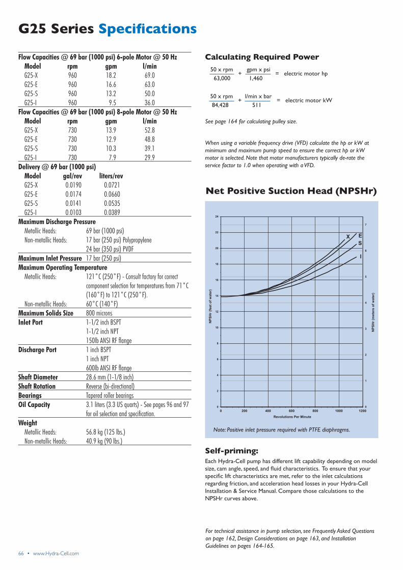
X E
S
I
Net Positive Suction Head (NPSHr)
Self-priming: Each Hydra-Cell pump has different lift capability depending on model size,camangle,speed,andfluidcharacteristics.Toensurethatyourspecificliftcharacteristicsaremet,refertotheinletcalculationsregarding friction, and acceleration head losses in your Hydra-Cell Installation & Service Manual. Compare those calculations to the NPSHrcurvesabove.
Note: Positive inlet pressure required with PTFE diaphragms.
50 x rpm +l/minxbar
= electric motor kW 84,428 511
See page 164 for calculating pulley size.
www.Hydra-Cell.com • 67
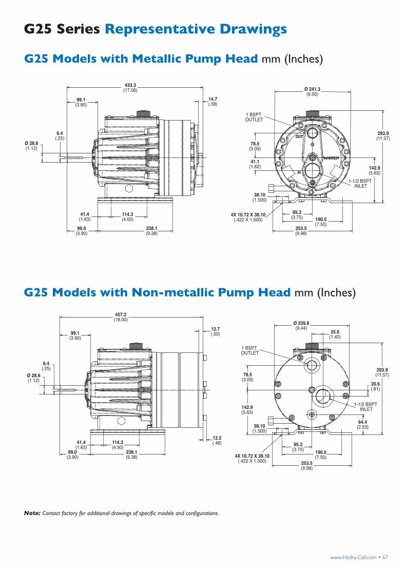
G25 Series Representative Drawings
G25 Models with Metallic Pump Head mm (Inches)
433.3(17.06)
99.1(3.90)
99.0(3.90)
6.4(.25)
Ø 28.6(1.12)
41.4(1.63)
114.3(4.50)
238.1(9.38)
14.7(.58)
Ø 241.3(9.50)
1 BSPT OUTLET
293.9(11.57)
142.9(5.63)
1-1/2 BSPT INLET
4X 10.72 X 38.10(.422 X 1.500)
38.10(1.500)
95.3(3.75)
253.5(9.98)
190.5(7.50)
41.1(1.62)
78.5(3.09)
G25 Models with Non-metallic Pump Head mm (Inches)
457.2(18.00)
99.1(3.90)
99.0(3.90)
6.4(.25)
41.4(1.63)
114.3(4.50)
238.1(9.38)
12.7(.50)
12.2(.48)
Ø 28.6(1.12)
1 BSPT OUTLET
4X 10.72 X 38.10(.422 X 1.500)
38.10(1.500)
95.3(3.75)
253.5(9.98)
190.5(7.50)
142.9(5.63)
78.5(3.09)
64.4(2.53)
20.6(.81)
Ø 239.8(9.44)
293.9(11.57)
35.6(1.40)
1-1/2 BSPT INLET
Note: Contact factory for additional drawings of specific models and configurations.
68 • www.Hydra-Cell.com
G25 Series Adapters/Valves
Pump/Motor Adapter mm (Inches)
Part Number: A04-041-1201
Must be ordered separately for G25 models for use withIEC132framemotors,B5flange.
NEMA adapter available - consult factory.
Part Number: A04-041-1203
Must be ordered separately for G25 models for use withIEC160framemotors,B14flange.
NEMA adapter available - consult factory.
Part Number: A04-041-1205
Must be ordered separately for G25 models for use withIEC160-180framemotors,B5flange.
NEMA adapter available - consult factory.
202.3 (7.97)
103.2 (4.06)
Ø 120.7 (4.75)MAX COUPLER O.D.
Ø 327.7 (12.90)
A seal-less C63 Pressure Regulating Valve is recommended for Hydra-Cell G25 pumping systems, especially for high-pressure requirements or whenhandlingdirtyfluids.
See page 88 for more information.
A C23 Pressure Regulating Valve provides a capable, lower-cost alternative to C63 valves for Hydra-Cell G25 pumping systems.
See page 84 for more information.
Valve Selection
208.4 (8.21)
109.3 (4.30)
Ø 120.7 (4.75)MAX COUPLER O.D.
Ø 249.9 (9.84)
207.9 (8.19)
108.8 (4.28)
Ø 120.7 (4.75)MAX COUPLER O.D.
Ø 327.7 (12.90)
www.Hydra-Cell.com • 69
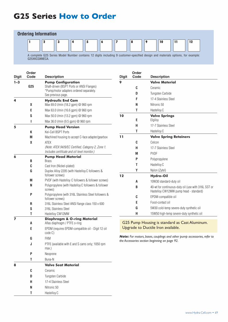
Ordering Information
G25 Series How to Order
A complete G25 Series Model Number contains 12 digits including 9 customer-specified design and materials options, for example: G25XKCGNNECA.
1-3 Pump Configuration G25 Shaft-driven (BSPT Ports or ANSI Flanges) *Pump/motor adapters ordered separately. See previous page.
4 Hydraulic End Cam X Max 69.0 l/min (18.2 gpm) @ 960 rpm
E Max 63.0 l/min (16.6 gpm) @ 960 rpm
S Max 50.0 l/min (13.2 gpm) @ 960 rpm
I Max 36.0 l/min (9.5 gpm) @ 960 rpm
5 Pump Head Version K Kel-Cell BSPT Ports M Machined housing to accept C-face adapter/gearbox
X ATEX (Note: ATEX 94/9/EC Certified, Category 2, Zone 1. Includes certificate and oil level monitor.)6 Pump Head Material B Brass C Cast Iron (Nickel-plated) G Duplex Alloy 2205 (with Hastelloy C followers & follower screws) M PVDF (with Hastelloy C followers & follower screws) N Polypropylene (with Hastelloy C followers & follower screws) P Polypropylene (with 316L Stainless Steel followers & follower screws) R 316L Stainless Steel ANSI flange class 150 x 600 S 316L Stainless Steel T Hastelloy CW12MW7 Diaphragm & O-ring Material A Aflas diaphragm / PTFE o-ring
E EPDM (requires EPDM-compatible oil - Digit 12 oil code C)
G FKM
J PTFE (available with E and S cams only; 1050 rpm max.)
P Neoprene
T Buna-N
8 Valve Seat Material
C Ceramic
D Tungsten Carbide
H 17-4 Stainless Steel
N Nitronic 50
T Hastelloy C
9 Valve Material
C Ceramic
D Tungsten Carbide
F 17-4 Stainless Steel
N Nitronic 50
T Hastelloy C
10 Valve Springs E Elgiloy
H 17-7 Stainless Steel
T Hastelloy C
11 Valve Spring Retainers
C Celcon
H 17-7 Stainless Steel
M PVDF
P Polypropylene
T Hastelloy C
Y Nylon (Zytel)
12 Hydra-Oil
A 10W30 standard-duty oil
B 40-wt for continuous-duty oil (use with 316L SST or Hastelloy CW12MW pump head - standard)
C EPDM-compatible oil
E Food-contact oil
G 5W30 cold-temp severe-duty synthetic oil
H 15W50 high-temp severe-duty synthetic oil
Order Digit Code Description
Order Digit Code Description
Note: For motors, bases, couplings and other pump accessories, refer to the Accessories section beginning on page 92.
G25 Pump Housing is standard as Cast Aluminum. UpgradetoDuctileIronavailable.