Solid State Relay G3RV 1 Ordering Information List of Models SSR and Socket Combinations Classification Enclosure rating Input voltage Type of connection Contact form SPST Plug-in terminals General-purpose Unsealed AC/DC Screw terminals G3RV-SL700 Push-in terminals G3RV-SL500 Input voltage Screw terminals Push-in terminals 12 VDC G3RV-SL700-D DC12 G3RV-SL500-D DC12 G3RV-SL700-A(L) DC12 G3RV-SL500-A(L) DC12 24 VDC G3RV-SL700-D DC24 G3RV-SL500-D DC24 G3RV-SL700-A(L) DC24 G3RV-SL500-A(L) DC24 24 VAC/DC G3RV-SL700-D AC/DC24 G3RV-SL500-D AC/DC24 G3RV-SL700-A(L) AC/DC24 G3RV-SL500-A(L) AC/DC24 48 VAC/DC G3RV-SL700-D AC/DC48 G3RV-SL500-D AC/DC48 G3RV-SL700-A(L) AC/DC48 G3RV-SL500-A(L) AC/DC48 110 VAC G3RV-SL700-D AC110 G3RV-SL500-D AC110 G3RV-SL700-A(L) AC110 G3RV-SL500-A(L) AC110 230 VAC G3RV-SL700-D AC230 G3RV-SL500-D AC230 G3RV-SL700-A(L) AC230 G3RV-SL500-A(L) AC230 Relay and Socket Combinations are c UL us listed. LISTED Slimmest OMRON plug-in SSR with maximum width 6.2 mm • Long electrical life and high speed switching • Large plug-in terminals for reliable connection • G3RV-D (DC load) models can manage resistive loads of 100 µA to 3.0 A • LED indicator for visible operation checking • Convenient quick electrical connections possible with G3RV push-in models and cross bar connectors • Low power consumption for energy savings • G3RV is cUL listed when correct relay is matched with the G3RV Socket Model Number Structure Model Number Legend 1. Basic Model Name G3RV: Solid State Relay 2. Auxiliary Type Designation SL: Slim Solid State Relay and socket combination 3. Wire Connection 5. Input Voltage 700: Screw Terminals (Complete part numbers listed in the SSR and Socket 500: Push-in (screwless) terminals Combinations Chart below) 4. Output voltage specifications A(L): AC Output .. TRIAC * A: with Zero cross function AL: without Zero cross function D: DC Output .. MOS FET 1 2 3 4 5 G3RV-SL - L Solid State Relays G3RV
Transcript
Solid State Relay G3RV 1
Solid State Relays G3RV 1
Ordering Information
List of Models
SSR and Socket Combinations
Classification Enclosure rating Input voltage Type of connection Contact formSPST
Note: Relay and Socket Combinationsare cULus listed.
LISTED
Slimmest OMRON plug-in SSR with maximum width 6.2 mm• Long electrical life and high speed switching• Large plug-in terminals for reliable connection• G3RV-D (DC load) models can manage resistive loads of
100 µA to 3.0 A• LED indicator for visible operation checking• Convenient quick electrical connections possible with G3RV
push-in models and cross bar connectors• Low power consumption for energy savings• G3RV is cUL listed when correct relay is matched with the
G3RV Socket
Model Number Structure
Model Number Legend
1. Basic Model NameG3RV: Solid State Relay
2. Auxiliary Type DesignationSL: Slim Solid State Relay and socket combination
3. Wire Connection 5. Input Voltage700: Screw Terminals (Complete part numbers listed in the SSR and Socket500: Push-in (screwless) terminals Combinations Chart below)
4. Output voltage specificationsA(L): AC Output .. TRIAC
* A: with Zero cross function AL: without Zero cross functionD: DC Output .. MOS FET
1 2 3 4 5G3RV-SL - L
Solid State Relays
G3RV
2
Specifications
Solid State Relay G3RV
2 Solid State Relays G3RV
Specifications
Ratings (at an Ambient Temperature of 25°C)
Input
G3RV-SL700/500-A Series
G3RV-SL700/500-AL Series
G3RV-SL700/500-D Series
Output
Rated voltage Rated current Must operate voltage
Must release voltage
Input voltage
AC DC % of rated voltage
50 Hz 60 Hz
12 VDC --- --- 15 mA 10.8V 1V ±10%
24 VDC --- --- 12 mA 21.6V
24 VAC/DC 20 mA 21 mA 11 mA 21.6V
48 VAC/DC 10 mA 11 mA 6 mA 43.2V
110 VAC 7.5 mA 8.2 mA --- 99V
230 VAC 7.3 mA 8.6 mA --- 207V
Rated voltage Rated current Must operate voltage
Must release voltage
Input voltage
AC DC % of rated voltage
50 Hz 60 Hz
12 VDC --- --- 8 mA 10.8V 1V ±10%
24 VDC --- --- 4.5 mA 21.6V
24 VAC/DC 10.7 mA 11.1 mA 4.3 mA 21.6V
48 VAC/DC 9.6 mA 10.2 mA 6 mA 43.2V
110 VAC 6.8 mA 7.5 mA --- 99V
230 VAC 6.8 mA 8.1 mA --- 207V
Item G3RV-SL700/500-A(L) G3RV-SL700/500-D
Rated load voltage AC100~240V (50/60Hz) DC5~24V
Load voltage range AC75~264V (50/60Hz) DC3~26.4V
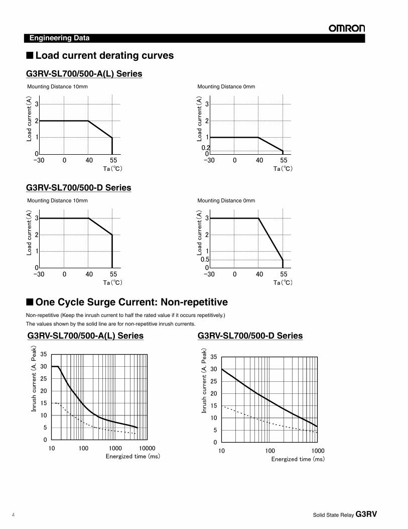
Load current 0.1~2A (Ta=40°C) 100µA~3A (Ta=40°C)
Inrush current 30A (60Hz/1cycle) 30A (60Hz/1cycle)
Permissible I2t ; Joule Integral (Reference value)
Cable length as indictadby model number.@@@ = length in centimeters
Split into 4 sectionsLength = 30 cm
40 Wire
B
A
D
C
Control line AWG26/0.14 mm2, tin-plated copperDiameter cable 10.6 mm (one end splits into 4 sections: A, B, C, DOperating voltage 60 VDCContinuous current per signal wire 0.5 AMax. total current, 4 bytes, each 1.0 ATest voltage 0.5 KV, 50 Hz, 1 minOperating temperature range –20°C to +50°C
P2RV-AC
C
Cable, single sided 10 pole IDC connector, to connect to P2RVC-8-O-F
10 pole IDC mounting to P2RVC-8-O-F
Technical data
List of ModelsModel number Cable length
P2RV-A100C 1.0 mP2RV-A200C 2.0 mP2RV-A300C 3.0 mP2RV-A500C 5.0 m
WHITEGREYPURPLEBLUEGREENYELLOWORANGEREDBROWNBLACK
10987654321
Ope
n en
d
Cable length as indictadby model number.@@@ = length in centimeters
Outer isolation removedLength = 30 cm
10 Wire
Control line AWG26/0.14 mm2, tin-plated copperDiameter cable 6.8 mmOperating voltage 60 VDCContinuous current per signal wire 0.5 AMax. total current 1.0 ATest voltage 0.5 KV, 50 Hz, 1 minOperating temperature range –20∞C to +50∞C
Solid State Relay G3RV
Accessories
7
6 Solid State Relays G3RV
SSR for Maintenance (Replacement SSRs)
Model Number Legend
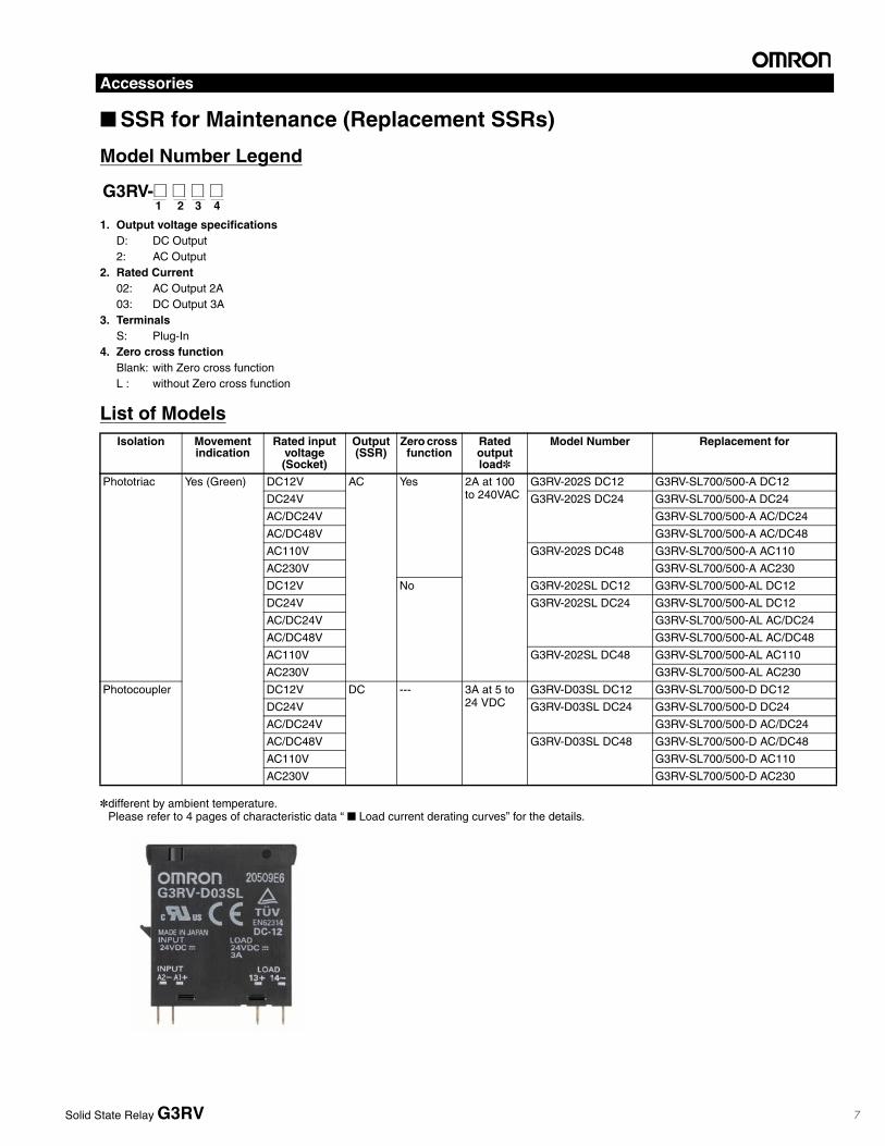
1. Output voltage specificationsD: DC Output2: AC Output
2. Rated Current02: AC Output 2A03: DC Output 3A
3. TerminalsS: Plug-In
4. Zero cross functionBlank: with Zero cross functionL : without Zero cross function
List of Models
*different by ambient temperature.Please refer to 4 pages of characteristic data “ Load current derating curves” for the details.
1 2 3 4G3RV-@ @ @ @
Isolation Movement indication
Rated input voltage (Socket)
Output (SSR)
Zero cross function
Rated output load*
Model Number Replacement for
Phototriac Yes (Green) DC12V AC Yes 2A at 100 to 240VAC
G3RV-202S DC12 G3RV-SL700/500-A DC12
DC24V G3RV-202S DC24 G3RV-SL700/500-A DC24
AC/DC24V G3RV-SL700/500-A AC/DC24
AC/DC48V G3RV-SL700/500-A AC/DC48
AC110V G3RV-202S DC48 G3RV-SL700/500-A AC110
AC230V G3RV-SL700/500-A AC230
DC12V No G3RV-202SL DC12 G3RV-SL700/500-AL DC12
DC24V G3RV-202SL DC24 G3RV-SL700/500-AL DC12
AC/DC24V G3RV-SL700/500-AL AC/DC24
AC/DC48V G3RV-SL700/500-AL AC/DC48
AC110V G3RV-202SL DC48 G3RV-SL700/500-AL AC110
AC230V G3RV-SL700/500-AL AC230
Photocoupler DC12V DC --- 3A at 5 to 24 VDC
G3RV-D03SL DC12 G3RV-SL700/500-D DC12
DC24V G3RV-D03SL DC24 G3RV-SL700/500-D DC24
AC/DC24V G3RV-SL700/500-D AC/DC24
AC/DC48V G3RV-D03SL DC48 G3RV-SL700/500-D AC/DC48
AC110V G3RV-SL700/500-D AC110
AC230V G3RV-SL700/500-D AC230
Solid State Relay G3RV
Accessories
8
Accessories
Solid State Relays G3RV 7
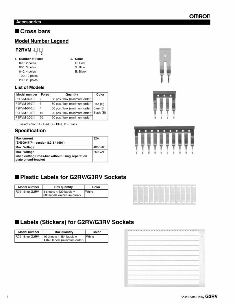
Cross bars
Model Number Legend
1. Number of Poles 2. Color020: 2 poles R: Red030: 3 poles S: Blue040: 4 poles B: Black100: 10 poles200: 20 poles
List of Models
@ select color: R = Red, S = Blue, B = Black
Specification
Plastic Labels for G2RV/G3RV Sockets
Labels (Stickers) for G2RV/G3RV Sockets
Model number Poles Quantity Color
P2RVM-020@ 2 60 pcs / box (minimum order)
Red (R)Blue (S)Black (B)
P2RVM-030@ 3 60 pcs / box (minimum order)
P2RVM-040@ 4 60 pcs / box (minimum order)
P2RVM-100@ 10 20 pcs / box (minimum order)
P2RVM-200@ 20 20 pcs / box (minimum order)
Max current(EN60947-7-1 section 8.3.3 / 1991)
32A
Max. Voltage 400 VAC
Max. Voltagewhen cutting Cross-bar without using separation plate or end-bracket
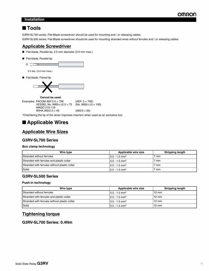
*Chamfering the tip of the driver improves insertion when used as an exclusive tool.
Applicable Wires
Applicable Wire Sizes
G3RV-SL700 Series
Box clamp technology
G3RV-SL500 Series
Push-in technology
Tightening torque
G3RV-SL700 Series: 0.4Nm
2.5 dia. (3.0 mm max.)
Cannot be used.
Flat-blade, Flared-tip
Flat-blade, Parallel-tip
Wire type Applicable wire size Stripping length
Stranded without ferrules 0.5 - 1.5 mm2 7 mm
Stranded with ferrules and plastic collar 0.5 - 1.5 mm2 7 mm
Stranded with ferrules without plastic collar 0.5 - 1.5 mm2 7 mm
Solid 0.5 - 1.5 mm2 7 mm
Wire type Applicable wire size Stripping length
Stranded without ferrules 0.5 - 1.5 mm2 12 mm
Stranded with ferrules and plastic collar 0.5 - 1.5 mm2 12 mm
Stranded with ferrules without plastic collar 0.5 - 1.5 mm2 12 mm
Solid 0.5 - 1.5 mm2 12 mm
Solid State Relay G3RV
Installation
Solid State Relay G3RV
12
Solid State Relays G3RV 11
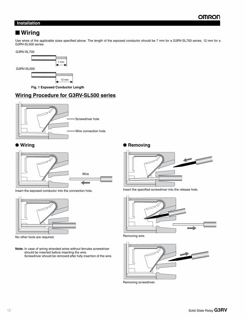
WiringUse wires of the applicable sizes specified above. The length of the exposed conductor should be 7 mm for a G3RV-SL700 series, 12 mm for aG3RV-SL500 series.
Wiring Procedure for G3RV-SL500 series
Wiring
Insert the exposed conductor into the connection hole.
No other tools are required.
Note: In case of wiring stranded wires without ferrules screwdriver should be inserted before inserting the wire. Screwdriver should be removed after fully insertion of the wire.
Removing
Insert the specified screwdriver into the release hole.
Removing wire.
Removing screwdriver.
7 mm
Fig. 1 Exposed Conductor Length
12 mm
G3RV-SL700
G3RV-SL500
Screwdriver hole
Wire connection hole
Wire
Solid State Relay G3RV
Installation
13
12 Solid State Relays G3RV
Precautions
Precautions for Connection• Do not move the screwdriver up, down, or from side to side while it
is inserted in the hole. Doing so may cause damage to internal components (e.g., deformation of the clamp spring or cracks in the housing) or cause deterioration of insulation.
• Do not insert the screwdriver at an angle. Doing so may break the side of socket and result in a short-circuit.
• Do not insert two or more wires in the hole. Wires may come in contact with the spring causing a temperature rise or be subject to sparks.
• Insert the screwdriver along the hole wall as shown below.
• If lubricating liquid, such as oil, is present on the tip of screwdriver, the screwdriver may fall out resulting in injury to the operator.
• Insert the screwdriver into the bottom of the hole. It may not be possible to connect cables properly if the screwdriver is inserted incorrectly.
General Precautions• Do not use the product if it has been dropped on the ground.
Dropping the product may adversely affect performance.• Confirm that the socket is securely attached to the mounting track
before wiring. If the socket is mounted insecurely it may fall and injure the operator.
• Ensure that the socket is not charged during wiring and maintenance. Not doing so may result in electric shock.
• Do not pour water or cleansing agents on the product. Doing so may result in electric shock.
• Do not use the socket in locations subject to solvents or alkaline chemicals.
• Do not use the socket in locations subject to ultraviolet light (e.g., direct sunlight). Doing so may result in markings fading, rust, corrosion, or resin deterioration.
• Do not dispose the product in fire.
Removing from Mounting RailTo remove the socket from the mounting rail, insert the tip of screwdriver in the fixture rail, and move it in the direction shown below.
Screwdriver
Solid State Relay G3RVSolid State Relay G3RV
Precautions
14
Precautions
Solid State Relays G3RV 13
Definition of Precautionary Information
Precautions for Safe Use Shipping
When shipping the G3RV, be sure to avoid the following:• Conditions where the G3RV is exposed to water.
• High ambient temperatures and humidity.
• Inadequate packaging
Failure to avoid these conditions while shipping G3RV will lead to damage, malfunction, or deterioration.
Operating and Storage Locations
Do not use or store the G3RV in the locations listed below. Failure to do so may result in damage, malfunction, or deterioration of performance characteristics.• Locations subject to rain or water drops.
• Locations subject to exposure to water, or oil, or chemicals.
• Locations subject to high temperatures or high humidity.
• Locations subject to ambient temperatures outside the range from -30 to +100 centigrade.
• Locations subject to relative humidity outside the range 45% to 85%.
• Locations subject to corrosive or flammable gases.
• Locations subject to dust (especially iron dust) or salts.
• Locations subject to barrier.
• Locations subject to static electricity or other forms of noise.
• Locations subject to strong electromagnetic fields.
• Locations subject to possible exposure to radioactivity.
Handling
• Be sure to provide adequate air flow to G3RV. Failure to do so can cause the G3RV to overheat leading to short circuit and burning.
• Do not install G3RV Relay with bent terminals into the socket. Doing so could lead to poor electrical connection and hazardous conditions.
• Be sure to mount G3RV's with clean hands. Performing mounting with oil stained hands or coated with metal powder could result in hazardous outcomes.
Mounting
• Be sure to mount the G3RV in the specified orientation. Mounting the G3RV in a different orientation could lead to abnormal heat generation causing output elements to short leading to burning.
• G3RV's are SSR's and generate heat. Be sure to control ambient temperature in setting where G3RV is used. If mounted in an enclosed space, install a fan to insure G3RV is properly ventilated.
• Be sure that the G3RV clicks into place when mounting it to DIN Track. The G3RV may fall if it is not mounted correctly.
Wiring
• Use a wire an adequate size for current to be applied. Abnormal heating of wire may cause burning.
• Do not use any wires with damaged sheaths. These may cause electric shock.
• Confirm that wiring to G3RV Socket is not used in pipe or duct for high voltage power supply. Using a wire in pipe or duct connected to high voltage power supply will generate induction causing malfunction or damage.
• Be sure to conduct wiring with the power supply turned OFF. Touching the terminals when they are charged may occasionally result in minor electric shock.
Using
• Select a load within the rated range. Inappropriate load may cause misoperation, trouble or burning.
• Select the power supply within the rated frequency range. Inappropriate power frequency may cause misoperation, trouble or burning.
Precautions for Correct Use G3RV uses electronics parts inside, so that any dropping,
vibration, and physical shock beyond the standard level should be prevented. Failure to do so may result in damage, malfunction, or deterioration of performance characteristics.
Be sure to use tightening torque of 0.4 N·m for screw terminal G3RV. Failure to do so could result in short circuit failure and burning.
Be sure to use proper voltage/current to G3RV input and output terminals. Failure to do so could result in short circuit failure and burning.
WARNING
Indicates a potentially hazardous situation which, if not avoided, will result in minor or moderate injury, or may result in serious injury or death. Additionally there may be significant property damage.
CAUTION A potentially hazardous situation by misuse, may result in property damage only accident.
CAUTION
Minor hazard by electric shock may occasionally occur. Do not touch the G3RV's terminal (Charging part) while the power supply turned on.
The G3RV may occasionally rupture in case of a short circuit.To protect against short-circuit accident, install a protective device, such as a quick-burning fuse or a circuit breaker or the like, on the power supply.
Minor hazard by electric shock may occasionally occur. Do not touch the G3RV's main circuit terminals immediately after the power is turned OFF. The internal snubber circuit is charged. * 202S,SL,G3RV-A(L) Type only
Minor hazard by burns may occasionally occur. Do not touch the G3RV or the heat sink either while the power supply is ON, or immediately after the power is turned OFF.The G3RV and the heat sink will be hot.
Solid State Relay G3RV
15
Safety Precautions
14 Solid State Relays G3RV
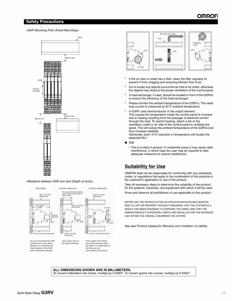
Mounting<SSR Mounting Pitch (Panel Mounting)>
<Relations between SSR and duct (Depth of duct)>
<Ventilation Outside the Control Panel>
* If the air inlet or outlet has a filter, clean the filter regularly to prevent it from clogging and ensuring efficient flow of air.
* Do no locate any objects around the air inlet or air outlet, otherwise the objects may obstruct the proper ventilation of the control panel.
* A heat exchanger, if used, should be located in front of the G2RVs to ensure the efficiency of the heat exchanger.
* Please monitor the ambient temperature of the G3RV's. The rated load current is measured at 25°C ambient temperature.
* A G3RV uses semiconductor in the output element. This causes the temperature inside the control panel to increase due to heating resulting from the passage of electrical current through the load. To restrict heating, attach a fan to the ventilation outlet or air inlet of the control panel to ventilate the panel. This will reduce the ambient temperature of the G3RVs and thus increase reliability. (Generally, each 10°C reduction in temperature will double the expected life.)EMI• This is a class A product. In residential areas it may cause radio
interference, in which case the user may be required to take adequate measures to reduce interference.
Suitability for UseOMRON shall not be responsible for conformity with any standards, codes, or regulations that apply to the combination of the products in the customer's application or use of the product.Take all necessary steps to determine the suitability of the product for the systems, machines, and equipment with which it will be used. Know and observe all prohibitions of use applicable to this product.
NEVER USE THE PRODUCTS FOR AN APPLICATION INVOLVING SERIOUS RISK TO LIFE OR PROPERTY WITHOUT ENSURING THAT THE SYSTEM AS A WHOLE HAS BEEN DESIGNED TO ADDRESS THE RISKS, AND THAT THE OMRON PRODUCT IS PROPERLY RATED AND INSTALLED FOR THE INTENDED USE WITHIN THE OVERALL EQUIPMENT OR SYSTEM.
See also Product catalog for Warranty and Limitation of Liability.
Duct
60mm min.
80mm min.30mm min.
SSR
Vertical direction
Counter measure(1)Duct Depth Counter measure(2)
Duct or air flow obstruction
The depth of SSR
SSR SSR SSR
Vertical direction
Duct or air flow obstruction Duct or air flow obstruction
Duct or air flow obstruction
The recommended width is 1/2 as large as the depth of SSR or less Duct or air flow
obstruction
Air flow Duct or air flow obstruction
Do not surrounded the SSRwith the duct in the depth direction, or otherwise the heat radiation of the S5R will be adversely affected.
If the height of the ducts can not be lowered, place the SSR or a metal base so that they are not surrounded by the ducts.
Use a short duct in the depth direction.
Metal base
SSR SSRSSR
Air inlet
Be aware of air flow
Duct
Ventllation outlet
In the interest of product improvement, specifications are subject to change without notice.
ALL DIMENSIONS SHOWN ARE IN MILLIMETERS.To convert millimeters into inches, multiply by 0.03937. To convert grams into ounces, multiply by 0.03527.
Cat. No. J180-E1-02Solid State Relay G3RVSolid State Relay G3RV
16
Read and Understand This CatalogPlease read and understand this catalog before purchasing the products. Please consult your OMRON representative if you have any questions orcomments.
Warranty and Limitations of Liability
WARRANTYOMRON's exclusive warranty is that the products are free from defects in materials and workmanship for a period of one year (or other period if specified)from date of sale by OMRON.
OMRON MAKES NO WARRANTY OR REPRESENTATION, EXPRESS OR IMPLIED, REGARDING NON-INFRINGEMENT, MERCHANTABILITY, ORFITNESS FOR PARTICULAR PURPOSE OF THE PRODUCTS. ANY BUYER OR USER ACKNOWLEDGES THAT THE BUYER OR USER ALONE HASDETERMINED THAT THE PRODUCTS WILL SUITABLY MEET THE REQUIREMENTS OF THEIR INTENDED USE. OMRON DISCLAIMS ALL OTHERWARRANTIES, EXPRESS OR IMPLIED.
LIMITATIONS OF LIABILITYOMRON SHALL NOT BE RESPONSIBLE FOR SPECIAL, INDIRECT, OR CONSEQUENTIAL DAMAGES, LOSS OF PROFITS OR COMMERCIAL LOSSIN ANY WAY CONNECTED WITH THE PRODUCTS, WHETHER SUCH CLAIM IS BASED ON CONTRACT, WARRANTY, NEGLIGENCE, OR STRICTLIABILITY.
In no event shall the responsibility of OMRON for any act exceed the individual price of the product on which liability is asserted.
IN NO EVENT SHALL OMRON BE RESPONSIBLE FOR WARRANTY, REPAIR, OR OTHER CLAIMS REGARDING THE PRODUCTS UNLESSOMRON'S ANALYSIS CONFIRMS THAT THE PRODUCTS WERE PROPERLY HANDLED, STORED, INSTALLED, AND MAINTAINED AND NOTSUBJECT TO CONTAMINATION, ABUSE, MISUSE, OR INAPPROPRIATE MODIFICATION OR REPAIR.
Application Considerations
SUITABILITY FOR USEOMRON shall not be responsible for conformity with any standards, codes, or regulations that apply to the combination of products in the customer'sapplication or use of the products.
At the customer's request, OMRON will provide applicable third party certification documents identifying ratings and limitations of use that apply to theproducts. This information by itself is not sufficient for a complete determination of the suitability of the products in combination with the end product,machine, system, or other application or use.
The following are some examples of applications for which particular attention must be given. This is not intended to be an exhaustive list of all possibleuses of the products, nor is it intended to imply that the uses listed may be suitable for the products:
• Outdoor use, uses involving potential chemical contamination or electrical interference, or conditions or uses not described in this catalog.
• Nuclear energy control systems, combustion systems, railroad systems, aviation systems, medical equipment, amusement machines, vehicles,safety equipment, and installations subject to separate industry or government regulations.
• Systems, machines, and equipment that could present a risk to life or property.
Please know and observe all prohibitions of use applicable to the products.
NEVER USE THE PRODUCTS FOR AN APPLICATION INVOLVING SERIOUS RISK TO LIFE OR PROPERTY WITHOUT ENSURING THAT THESYSTEM AS A WHOLE HAS BEEN DESIGNED TO ADDRESS THE RISKS, AND THAT THE OMRON PRODUCTS ARE PROPERLY RATED ANDINSTALLED FOR THE INTENDED USE WITHIN THE OVERALL EQUIPMENT OR SYSTEM.
PROGRAMMABLE PRODUCTSOMRON shall not be responsible for the user's programming of a programmable product, or any consequence thereof.
Disclaimers
CHANGE IN SPECIFICATIONSProduct specifications and accessories may be changed at any time based on improvements and other reasons.
It is our practice to change model numbers when published ratings or features are changed, or when significant construction changes are made.However, some specifications of the products may be changed without any notice. When in doubt, special model numbers may be assigned to fix orestablish key specifications for your application on your request. Please consult with your OMRON representative at any time to confirm actualspecifications of purchased products.
DIMENSIONS AND WEIGHTSDimensions and weights are nominal and are not to be used for manufacturing purposes, even when tolerances are shown.
PERFORMANCE DATAPerformance data given in this catalog is provided as a guide for the user in determining suitability and does not constitute a warranty. It may represent theresult of OMRON’s test conditions, and the users must correlate it to actual application requirements. Actual performance is subject to the OMRONWarranty and Limitations of Liability.
ERRORS AND OMISSIONSThe information in this document has been carefully checked and is believed to be accurate; however, no responsibility is assumed for clerical,typographical, or proofreading errors, or omissions.
2010.1In the interest of product improvement, specifications are subject to change without notice.