183
G486ESV AIO Rev. 0 + System Board User’s Manual - D26550610 -

G486ESV AIORev. 0 +
System BoardUser’s Manual
- D26550610 -

v Copyright 1995 by DFI, Inc.
All rights reserved.
No part of this document may be copied, reproduced inany form or by any means or used to make any trans-formation/adaptation without the prior written consentof DFI, Inc.
DFI, Inc. makes no warranties with respect to thisdocumentation and disclaims any implied warranties ofmerchantability, quality, or fitness for any particularpurpose. The information in this document is subject tochange without notice. DFI, Inc. reserves the right tomake revisions to this publication and to make changesto any and/or all parts of its content, at any time,without obligation to notify any person or entity of suchchanges. Further, DFI, Inc. assumes no responsibilityfor any errors that may appear in this document.
DFI is a registered trademark, and G486ESV AIO is atrademark of Diamond Flower, Inc. All other productnames mentioned are trademarks or registered trade-marks of their respective companies.

v FCC Statement on Class BThis equipment has been tested and found to complywith the limits for a Class B digital device, pursuant toPart 15 of the FCC rules. These limits are designed toprovide reasonable protection against harmful interfer-ence when the equipment is operated in a residentialinstallation. This equipment generates, uses and canradiate radio frequency energy and, if not installed andused in accordance with the instruction manual, maycause harmful interference to radio communications.However, there is no guarantee that interference willnot occur in a particular installation. If this equipmentdoes cause harmful interference to radio or televisionreception, which can be determined by turning theequipment off and on, the user is encouraged to try tocorrect the interference by one or more of the followingmeasures:
• Reorient or relocate the receiving antenna.• Increase the separation between the equipment and
the receiver.• Connect the equipment into an outlet on a circuit
different from that to which the receiver isconnected.
• Consult the dealer or an experienced radio TVtechnician for help.
Notice:
1. The changes or modifications not expresslyapproved by the party responsible for compliancecould void the user's authority to operate theequipment.
2. Shielded interface cables must be used in order tocomply with the emission limits.

1-11-31-7
2-12-12-22-22-32-32-62-62-82-8
2-82-112-132-152-172-212-232-282-282-482-542-552-572-602-612-612-62
v Table of Contents v
Introduction ..........................................................................Features and Specifications ...............................................Package Checklist ..............................................................
Installation Overview ..............................................................Preparing the Area .............................................................Handling the System Board ...............................................
Tips in Handling the System Board .............................Hardware Installation ..........................................................
Memory Installation ......................................................Installing the Modules ...........................................
Board Configuration ............................................................Jumper Settings ...........................................................
Jumper Settings for Display Type, PasswordClear, Internal/External Speaker andFlash EPROM ..................................................
Jumper Settings for VL-Bus Add-on Board ..........Jumper Settings for Built-in VGA ..........................Jumper Settings for Parallel Port ..........................Jumper Settings for Built-in LAN ..........................
Cache Configuration ....................................................Jumper Settings for Cache Memory .....................
CPU Installation and Upgrade .....................................Jumper Settings for CPUs ....................................Installing Upgrade CPUs .......................................
Upgrading the Video Memory from 1MB to 2MB ........Installing the Remote Boot ROM .................................
Installing the System Board ................................................Build-in Ports ......................................................................
Serial Ports ..................................................................Connecting the Serial Ports ..................................
Parallel Port .................................................................

2-622-632-642-642-652-652-662-662-662-672-682-692-692-702-702-71
3-113-13-23-53-63-7
3-103-113-113-123-133-143-14
4-14-14-2
Floppy Disk Drive Connector .............................................Connecting the Floppy Disk Cable .............................
IDE Hard Disk Connector ..................................................Connecting the IDE Hard Disk Interface ....................Adding a Second IDE Hard Drive ...............................Preparing an IDE Drive for Use ..................................
PS/2 Mouse Port ................................................................Analog Connector ...............................................................
Connecting the Analog Connector ..............................AUI Connector ....................................................................
Ethernet Cable .............................................................BNC Connector ..................................................................
Cheapernet Cable ........................................................Twisted-Pair Connector ......................................................
Twisted-Pair Cable ......................................................ECT-100 .............................................................................
Initial Setup Program .............................................................Award BIOS CMOS Setup Utility .......................................
Standard CMOS Setup ................................................BIOS Features Setup ..................................................Chipset Features Setup ...............................................Power Management Setup ..........................................Load BIOS Defaults .....................................................Load Setup Defaults ....................................................Password Setting .........................................................IDE HDD Auto Detection .............................................HDD Low Level Format ...............................................Save and Exit Setup ....................................................Exit Without Saving .....................................................
Setmode Configuration Utility ...............................................Setmode .............................................................................Main Function Manu ...........................................................

Configure Currently Enabled Card ..............................Configure Card from Disabled Card ............................Read the Configuration Registers ...............................Set Shared Memory Addresses ...................................Initialize Board and Perform Loopback Test ...............Quit and Return to DOS ..............................................
Configurating via the Command Line ................................Basic Manu and Keyboard Operation .........................
Getmode .............................................................................
LAN Software Driver Installation ..........................................Novell Netware ...................................................................
IPXSVR ........................................................................ODI ...............................................................................
Installing the DOS ODI Driver ..............................Installing the ODI Server Driver ............................
Microsoft LAN Manager and Windows for Workgroups .....Installing the Microsoft LAN Manager Drivers .............Installing the Windows for Workgroups Drivers ...........
Packet Driver ......................................................................Installing the Packet Driver ..........................................
SCO UNIX Streams Driver .................................................Installation Procedure ..................................................
VGA Software Driver Installation ..........................................
Troubleshooting Checklist ....................................................
Appendix A: Types of Modules ............................................Appendix B: System Error Report ........................................Appendix C: Memory & I/O Maps .........................................Appendix D: 16-Bit Slot Pin Assignments ...........................Appendix E: VL-Bus Slot Pin Assignments ........................Appendix F: Connector Pin Assingments ...........................
4-24-114-124-134-144-154-154-174-18
5-15-15-15-55-5
5-105-135-135-165-175-175-185-19
6-1
7-1
A-1B-1C-1D-1E-1F-1

Appendix G: Award BIOS Hard Disk Table ..........................Appendix H: LAN Software Diskettes ...................................Appendix I: Reference Table .................................................Appendix J: System Overview ..............................................
G-1H-1I-1J-1

Green All-In-One System Board
This page left intentionally blank.

G486ESV AIO
v IntroductionThe G486ESV AIO is an Energy Star Compliant all-in-one system board that supports the EnvironmentalProtection Agency's Green PC requirements. It reducesenergy consumption by automatically turning off periph-erals, or the entire system, when not in use.
The G486ESV AIO offers several advanced featuresintegrated into the system board. It has a VESAVL-Bus Windows accelerated VGA controller withdisplay resolutions of 640x480 with 16.8M colors,800x600 with 65536 colors, and 1024x768 with 256colors. If the video memory is 2MB, it can display1280x1024 with 256 colors. It also has an enhanced IDEcontroller, an ECP/EPP parallel port, two serial ports, aPS/2 mouse port and a PS/2 keyboard connector.
The G486ESV AIO accommodates the full series ofIntel 486TM, AMD and Cyrix 5V CPUs.
The G486ESV AIO may also use 3.3V CPUs:Intel486TM DX4, running at 75MHz and 100MHz,AMD 486DX2-66/80NV8T and AMD 486DX4-75/100NV8T, Cyrix's Cx486DX2V, running at 50MHz and66MHz or Cyrix's Cx486DX2V, running at 80MHz.
The G486ESV AIO is equipped with a riser card con-nector for ISA and VL-Bus expansion. The all-in-onesystem board design of the G486ESV AIO allows theuser the ability to add expansion cards to the systemwhile keeping deskspace required to a minimum. With ariser card, which is usually supplied by the computerchassis manufacturer, installed in the system, you can
Introduction u 1-1

Green All-In-One System Board
plug expansion boards in horizontally instead of verti-cally. The number of ISA and VL-Bus slots on the risercard will depend on the type of all-in-one case used.
The G486ESV AIO supports optional AUI, BNC andRJ-45 Ethernet ports and is NE2000/NE2000 Plus(widely used in Novell NetWare) and WD/SMCEthercard Plus 16 (widely used in the UNIX environ-ment) hardware compatible.
The system board can be configured to ten differentmemory sizes from 1MB to 64MB using 256Kx36,512Kx36, 1Mx36, 2Mx36, 4Mx36 and 8Mx36 HSIMmodules.
Note:This board must be installed in an “all-in-one stylecomputer chassis” with LPX/LPM form factor.
1-2 u Introduction

G486ESV AIO
Microprocessor• 5V CPUs
Intel 486SX/DX/DX2 (full series) and PentiumTM
OverDrive ProcessorAMD 486DX/DXL/DXL2 (full series)Cyrix 486SX/DX/DX2 (full series)
• 3.3V CPUsIntel 486DX4-75/100AMD 486DX2-66/80NV8T, 486DX4-75/100NV8TCyrix 486DX2V-50/66, 486DX2V-80 (custom
version)
Energy Efficient Design• Supports both 3.3V (optional) and 5V CPUs• Supports system power management• Supports CPU stopped clock• Supports optional external power management
switch• Supports power saving video mode• Optional low power on-board Ethernet
Flexible Power Management Scheme• Hardware supports auto-state transition mechanism• System BIOS supports Microsoft's APM and
provides basic power management control for DPMScompliant monitor and power saving peripherals
• Hardware provides flexible event-driven powermanagement scheme and easy CPU transition state(Ready, Standby and Suspend)
• Optional advanced SMM power management utilityprovided for sophisticated users
Features and Specifications
Introduction u 1-3

Green All-In-One System Board
High Performance VL-Bus Windows Accelerator• Uses S3 Trio64 (standard) or Trio32 GUI graphic
controller• 2MB (Trio32) or 2MB (Trio64)• Resolutions: 640x480, 16.8M colors, 75Hz
800x600, 65536 colors, 75Hz1024x768, 256 colors, 75Hz1280x1024, 256 colors, 75Hz (2MB)
• WinMark (1024x768, 256 colors, 70Hz,486DX2-66/486DX4-100, 2MB, Trio64):
486DX2-66 WinMark 3.11: 54 megapixels/secWinMark 4.0: 17 megapixels/sec
486DX4-100 WinMark 3.11: 61 megapixels/secWinMark 4.0: 23 megapixels/sec
Super I/O Interface and Fast IDE• Uses NS PC87332VF super I/O controller• Two NS16C550 compatible serial ports• One EPP/ECP parallel port• Supports 360K, 720K, 1.2MB, 1.44MB and
2.88MB floppy drives• Build-in fast IDE interface supports Mode 3 HDD
Industrial Standard Ethernet Controller (Optional)• Uses NS DP83905 or compatible Ethernet controller• NE2000, NE2000 Plus, SMC Ethercard Plus 16
hardware/software compatible• Supports Novell 2.15, 3.11, 4.01 and SCO UNIX• Supports 10Base-2 (COAX), 10Base-5 (AUI) and
10Base-T (Twisted-pair)• Supports Remote Boot ROM socket
System Chip Set• EC802GL: system and cache controller• EC100G: data buffer
1-4 u Introduction

G486ESV AIO
Introduction u 1-5
BIOS• Award system BIOS• Supports IDE HDDs larger than 528MB under DOS
(LBA mode only)• S3 VGA BIOS• Remote boot ROM (optional)• Flash EPROM and utility supported (optional)
Cache Memory• 128K, 256K, 512K or 1MB• Supports direct map write-back or write-through
cache
Memory Onboard• 1MB to 64MB
DRAM Type• 256Kx36, 512x36K, 1Mx36, 2Mx36, 4Mx36 and
8Mx36• Supports single and/or double density SIMMs• Four 72-pin SIMM sockets
CPU Socket• 237-pin ZIF socket (Intel Socket 3)
Slot• One riser card connector for ISA and VL-Bus
expansion
Connectors• Two DB-9P serial ports• One DB-25S parallel port• One IDE disk connector• One floppy drive connector• One DB-15 analog VGA connector

Green All-In-One System Board
1-6 u Introduction
• One VGA feature connector• Two mini-DIN-6 connectors for the PS/2 keyboard
and PS/2 mouse• One AUI, BNC and RJ-45 Ethernet port (optional)
Tooling Holes• LPX form factor
PCB• 4 layers, 33cm (12.9") x 22.8cm (8.9")

G486ESV AIO
Package Checklist
The G486ESV AIO package contains the followingitems:
• The G486ESV AIO system board• The G486ESV AIO user's manual• Four Trio32/64 utility/driver diskettes• Two NET700-EC/ET/ECT driver diskettes (optional)• One 34-pin floppy disk drive cable• One 40-pin IDE hard disk cable• One 15-pin AUI connector cable for chassis
mounting (optional)• One ECT-100: a card-edge bracket holding the AUI,
BNC and RJ-45 connectors (optional)
If any of these items are missing or damaged, pleasecontact your dealer or sales representative for assistance.
Introduction u 1-7

Green All-In-One System Board
2-1 u Installation Overview
v Installation OverviewThis chapter summarizes the steps in installing theG486ESV AIO system board into your system unit. Italso includes a description of the area in which youmust work and directions for memory installation.Before installing the system board, obtain the memoryyou plan to install. Please refer to the memory chart onpage 2-4 for the number and type of HSIM modulesneeded for the amount of memory you require.
Preparing the Area
Before unpacking the system board, make sure thelocation you have selected is relatively free of dust andstatic. Excessive exposure to dust, static electricity,direct sunlight, excessive humidity, extreme cold, andwater can damage the operational capabilities of yoursystem board. Avoid placing the unit on soft surfacessuch as beds and carpeted floors which can hinder aircirculation. These areas also attract static electricitywhich can damage some circuits on your system board.
Be sure that the power source has a properly grounded,three-pronged socket. It is essential that the powerconnection be properly grounded for correct functioningof your system board. For further protection, we recom-mend that you use a surge protection socket. This willprotect the system board from damage that may resultfrom a power surge on the line.
Move items that generate magnetic fields away fromyour system board, since magnetic fields can alsodamage your system board. Once you have selected theideal location, unpack the G486ESV AIO system boardcarefully.

G486ESV AIO
Handling the System Board
It is quite easy to inadvertently damage your systemboard even before installing it in your system unit.Static electrical discharge can damage computer compo-nents without causing any signs of physical damage.You must take extra care in handling the system boardto ensure against electrostatic build-up.
Tips in Handling the System Board
1) To prevent electrostatic build-up, leave the board inits anti-static bag until you are ready to install it.
2) Do all preparation work on a static-free surface withcomponents facing up.
3) Hold the system board by its edges only. Be carefulnot to touch any of the components, contacts or
connections, especially gold contacts on the board.
4) Avoid touching the pins or contacts on all modulesand connectors. Hold modules and connectors by
their ends.
Warning:Electrostatic discharge (ESD) can damage your upgradeprocessor, disk drives, add-in boards, and othercomponents. Perform the upgrade instructionprocedures described at an ESD workstation only. Ifsuch a station is not available, you can provide someESD portection by wearing an antistatic wrist strap andattaching it to a metal part of the system chassis. If awrist strap is unavailable, establish and maintaincontact with the system chassis throughout anyprocedures requiring ESD protection.
Installation Overview u 2-2
Green All-In-One System Board
2-3 u Installation Overview
Hardware Installation
Memory Installation
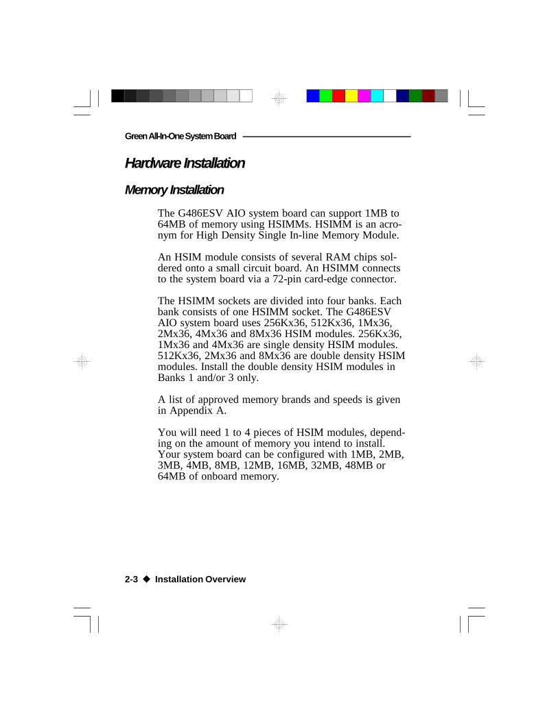
The G486ESV AIO system board can support 1MB to64MB of memory using HSIMMs. HSIMM is an acro-nym for High Density Single In-line Memory Module.
An HSIM module consists of several RAM chips sol-dered onto a small circuit board. An HSIMM connectsto the system board via a 72-pin card-edge connector.
The HSIMM sockets are divided into four banks. Eachbank consists of one HSIMM socket. The G486ESVAIO system board uses 256Kx36, 512Kx36, 1Mx36,2Mx36, 4Mx36 and 8Mx36 HSIM modules. 256Kx36,1Mx36 and 4Mx36 are single density HSIM modules.512Kx36, 2Mx36 and 8Mx36 are double density HSIMmodules. Install the double density HSIM modules inBanks 1 and/or 3 only.
A list of approved memory brands and speeds is givenin Appendix A.
You will need 1 to 4 pieces of HSIM modules, depend-ing on the amount of memory you intend to install.Your system board can be configured with 1MB, 2MB,3MB, 4MB, 8MB, 12MB, 16MB, 32MB, 48MB or64MB of onboard memory.
G486ESV AIO
Installation Overview u 2-4
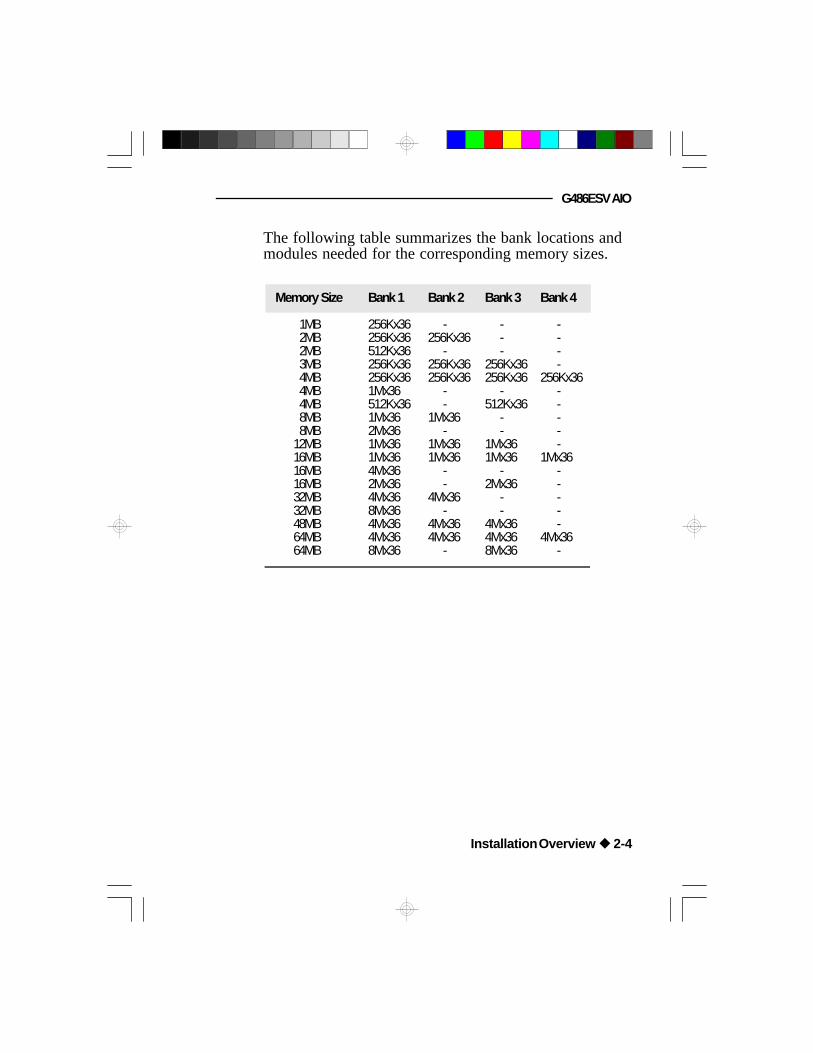
The following table summarizes the bank locations andmodules needed for the corresponding memory sizes.
Memory Size Bank 1 Bank 2 Bank 3 Bank 4
1MB 256Kx36 - - -2MB 256Kx36 256Kx36 - -2MB 512Kx36 - - -3MB 256Kx36 256Kx36 256Kx36 -4MB 256Kx36 256Kx36 256Kx36 256Kx364MB 1Mx36 - - -4MB 512Kx36 - 512Kx36 -8MB 1Mx36 1Mx36 - -8MB 2Mx36 - - -
12MB 1Mx36 1Mx36 1Mx36 -16MB 1Mx36 1Mx36 1Mx36 1Mx3616MB 4Mx36 - - -16MB 2Mx36 - 2Mx36 -32MB 4Mx36 4Mx36 - -32MB 8Mx36 - - -48MB 4Mx36 4Mx36 4Mx36 -64MB 4Mx36 4Mx36 4Mx36 4Mx3664MB 8Mx36 - 8Mx36 -

Green All-In-One System Board
2-5 u Installation Overview
ISA
Slot
VE
SA
Slot
ZIF Socket
EC802GL EC100G
Trio64/32
Locations of the HSIMM Socketson the G486ESV AIO System Board
SM4
SM2
SM3
SM1
Bank 4
Bank 3
Bank 2
Bank 1
Pin 1 of the HSIM socket

G486ESV AIO
1. Position the HSIM module above the HSIMMsocket, with the chips of the module facing thecenter of the system board.
2. Seat the module at an angle into the bank. Makesure it is completely seated. Tilt the module uprightuntil it locks in place in the socket.
Board Configuration
Installing the Modules
An HSIM module simply snaps into a socket on thesystem board. Pin 1 of the HSIMM must correspondwith Pin 1 of the socket.
Installation Overview u 2-6
Note:If you are using a DX2 or DX4 CPU, the correspondingjumpers must be set according to the CPU's base speed.Divide the speed of a DX2 CPU by two and the speed ofa DX4 CPU by three to come up with the CPU's basespeed. For example, if you are using a DX2-66 CPU,dividing 66 by 2 will give you 33. If you are using aDX4-75 CPU, dividing 75 by 3 will give you 25.

Green All-In-One System Board
2-7 u Installation Overview
CN1
ISA
Slot
VE
SA
Slot
SM1
SM2
SM3
SM4
ZIF Socket
EC802GL EC100G
Trio64/32
U53
U54
KB1J6CN3CN4CN5CN6
DP83905
CN2J5 CN2
J3
J2J4 PL1
JP4
JP5
JP2
JP89JP
35
JP90
JP26
JP18 JP17
JP28
JP6JP7 JP8
JP14
JP68
J13
JP83JP50
JP53
JP93
JP94
JP95JP97JP65
JP92
JP74JP75
JP91JP31
J9
JP66
JP73
JP81J11 JP86
JP57
JP58 - JP63
JP55JP38
J10
Locations of Jumpers and Connectorson the G486ESV AIO System Board
JP37JP36
J8

G486ESV AIO
Jumper Settings
Installation Overview u 2-8
Jumper Settings for Display Type, Password Clear, Internal/External Speaker and Flash EPROM
Flash EP
RO
M
J8
JP50 JP4
JP5
Locations of Jumpers JP4, JP5, J8 and JP50on the G486ESV AIO System Board

Green All-In-One System Board
2-9 u Installation Overview
Jumper JP4Display Type Select
Jumper JP4 must match the type of display adapterinstalled. If you are using the built-in VGA adapter or aVGA add-on card, set pins 1 and 2 to On. If you areusing a monochrome add-on card, set pins 2 and 3 toOn.
2
1
3
1-2 On: Color Display(Default)
2-3 On: Mono Display
2
1
3
Jumper JP5Password Clear
If you set a password in the “Password Setting” optionand forget your password, power off your system and setJumper JP5 to On to clear the password stored in yourCMOS. Now power on your system. After your systemhas detected the floppy or hard drive, turn it off againand set JP5 to Off.
On: Clear Password Off: Normal(Default)

G486ESV AIO
Installation Overview u 2-10
Jumper J8Internal/External Speaker
The G486ESV AIO comes with an internal speaker. Ifthere is a problem with the internal speaker, or if youprefer to use an external speaker, remove the jumperfrom pins 1 and 2 and connect the external speaker tothis jumper.
Jumper JP50Flash EPROM Voltage
The G486ESV AIO supports 5 Volt and 12 Volt FlashEPROM. If your system board is using an EPROM or 5Volt Flash EPROM, set Jumper JP50 pins 1 and 2 toOn. Change JP50 pins 2 and 3 to On if you are using a12 Volt Flash EPROM.
2-3 On:12V Flash EPROM
1-2 On:EPROM or 5V FlashEPROM (Default)
1 2 3 4
1-2 On: Internal Speaker(Default)
2
1
3
2
1
3

Green All-In-One System Board
2-11 u Installation Overview
Jumper Settings for VL-Bus Add-On Board
JP37JP36
Locations of Jumpers JP36 and JP37on the G486ESV AIO System Board

G486ESV AIO
Installation Overview u 2-12
Jumper JP36CPU External Clock Speed for VL-Bus Board
If a VL-Bus board is installed in the G486ESV AIOsystem board, Jumper JP36 pins 1 and 2 must be set toOn if the CPU external clock speed is greater than33MHz. Pins 2 and 3 must be set to On if the CPUexternal clock speed is less than or equal to 33MHz.
1 2 3 1 2 3
2-3 On: CPUExternal Clock Speed
< = 33MHz(Default)
1-2 On: CPUExternal Clock Speed
> 33MHz
Jumper JP37High Speed Mode for VL-Bus Board
Set Jumper JP37 pins 1 and 2 to On only if each of theVESA VL-Bus add-on boards, installed in the VL-Busslots on the riser card, supports Zero Wait State. If youare not sure whether your add-on boards support ZeroWait State, set JP37 pins 2 and 3 to On; otherwise, asystem error may occur.
1 2 3 1 2 3
2-3 On: One WaitState (Default)
1-2 On: Zero WaitState

Green All-In-One System Board
2-13 u Installation Overview
Jumper Settings for Built-in VGA
Location of Jumper JP68 on the G486ESV AIOSystem Board
JP68

G486ESV AIO
Installation Overview u 2-14
Jumper JP68Built-in VESA VGA Enable/Disable
The G486ESV AIO supports a 15-pin analog connectorbuilt onto the system board. If you wish to install aVGA add-on board, set pins 1-2 to On to disable thebuilt-in VGA. Install the VGA add-on board on the risercard.
1 2 3 1 2 3
2-3 On:Built-in VGA Enabled
(Default)
1-2 On:Built-in VGA Disabled

Green All-In-One System Board
2-15 u Installation Overview
Jumper Settings for Parallel Port
Location of Jumper JP26 on the G486ESV AIOSystem Board
JP26

G486ESV AIO
Jumper JP26ECP DMA Select
If your G486ESV AIO system board is using aNS PC87322 I/O chip, leave Jumper JP26 in its defaultsetting. If your G486ESV AIO is using a NS PC87332 I/O chip, it will support an ECP parallel port, allowingyou to use DMA Channel 1 or 3. Set Jumper JP26according to the DMA channel used by the systemboard.
2 4 6
1 3 5
1-3, 2-4 On: DMAChannel 1(Default)
2 4 6
1 3 5
3-5, 4-6 On: DMAChannel 3
Installation Overview u 2-16

Green All-In-One System Board
2-17 u Installation Overview
Jumper Settings for the Built-in LAN
Locations of Jumper JP35, JP89 and JP90on the G486ESV AIO System Board
JP89JP35
JP90
G486ESV AIO
Installation Overview u 2-18
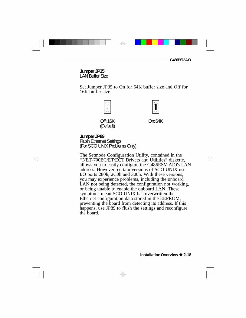
Set Jumper JP35 to On for 64K buffer size and Off for16K buffer size.
Off: 16K(Default)
On: 64K
Jumper JP89Flush Ethernet Settings(For SCO UNIX Problems Only)
Jumper JP35LAN Buffer Size
The Setmode Configuration Utility, contained in the“NET-700EC/ET/ECT Drivers and Utilities” diskette,allows you to easily configure the G486ESV AIO's LANaddress. However, certain versions of SCO UNIX useI/O ports 280h, 2C0h and 300h. With these versions,you may experience problems, including the onboardLAN not being detected, the configuration not working,or being unable to enable the onboard LAN. Thesesymptoms mean SCO UNIX has overwritten theEthernet configuration data stored in the EEPROM,preventing the board from detecting its address. If thishappens, use JP89 to flush the settings and reconfigurethe board.

Green All-In-One System Board
The default setting of Jumper JP89 is 2-3 On. Toreconfigure the board:
1. Power off your system.
2. Set Jumper JP89 to 1-2 On.
3. Power on your system.
4. Configure the board to IRQ3 and I/O port 300 usingthe SETMODE Configuration Utility.
5. Save the configuration to EEPROM.
6. Power off your system again.
7. Reset Jumper JP89 to 2-3 On.
8. Power on your system again to reconfigure yourboard.
2
1
3
2
1
3
2-3: On(Default)
1-2: On
2-19 u Installation Overview

G486ESV AIO
Jumper JP90Built-in LAN Enable/Disable
The G486ESV AIO supports AUI, BNC and RJ-45connectors built onto the system board. If you wish toinstall a LAN add-on board, set pins 2 and 3 to On todisable the built-in LAN. Install the LAN add-on boardon the riser card.
2
1
3
2
1
3
1-2 On: Enabled(Default)
2-3 On: Disabled
Installation Overview u 2-20

Green All-In-One System Board
Cache Configuration
The G486ESV AIO system board can be configured tocache sizes of 128KB, 256KB, 512KB and 1MB.256KB is the default size.
The SRAM socket is a dual socket, allowing you toinstall either a 32K x 8 or 128K x 8 SRAM. One 32K x8 or 128K x 8 SRAM tag RAM chip is required to storethe cacheable addresses. The system board automaticallydetects the cacheable system RAM size based on thesize of cache installed. SRAM and tag RAM chipsshould have speeds of 20ns.
2-21 u Installation Overview
Cache Size U1/U5/U9/U14 U2/U6/U10/U15 U21
128KB
256KB *512KB1MB
32Kx8
32Kx8128Kx8128Kx8
-
32Kx8-
128Kx8
32Kx8or
8Kx832Kx832Kx8128Kx8
* Default setting
Note:U1/U5/U9/U14 (Bank 0) and U2/U6/U10/U15 (Bank 1)are locations for the 32Kx8 SRAM or 128Kx8 SRAM.
When installing the cache chips, populate Bank 0 firstand then Bank 1. For example, to configure 128K ofcache memory, install four 32Kx8 chips in Bank 0 andleave the SRAM sockets of Bank 1 empty.
The table on the next page summarizes the cacheablesystem RAM size for the corresponding cache size.

G486ESV AIO
Installation Overview u 2-22
Cache Memory Cacheable System RAM Size
128KB 32MB256KB* 64MB512KB 64MB1MB 64MB
* Default setting
Locations of the SRAMs on theG486ESV AIO System Board
U1U5U9U14
Bank 0
Bank 1
U10U15 U2U6
U21 (Tag)
Green All-In-One System Board
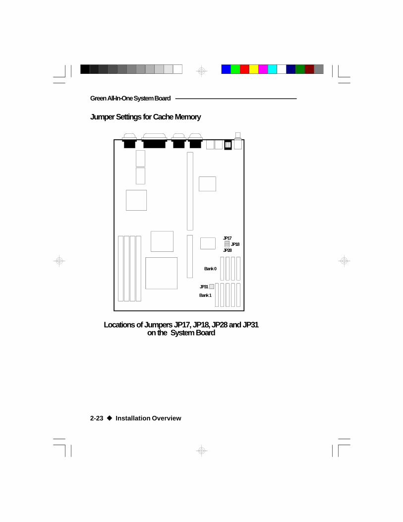
Jumper Settings for Cache Memory
Locations of Jumpers JP17, JP18, JP28 and JP31on the System Board
JP31
JP18JP17
JP28
2-23 u Installation Overview
Bank 0
Bank 1

G486ESV AIO
Installation Overview u 2-24
128KB Cache SRAM
Bank 0
32Kx8
32Kx8
32Kx8
32Kx8U14
U9
U5
U1
Bank 1
U10
U15
U21
1 2 3
JP28JP18JP17 1
3
5
2
4
6
JP31
Note:
This refers to an emptySRAM socket.
U6
U2
32Kx8/8Kx8 (TAG)
Green All-In-One System Board
2-25 u Installation Overview
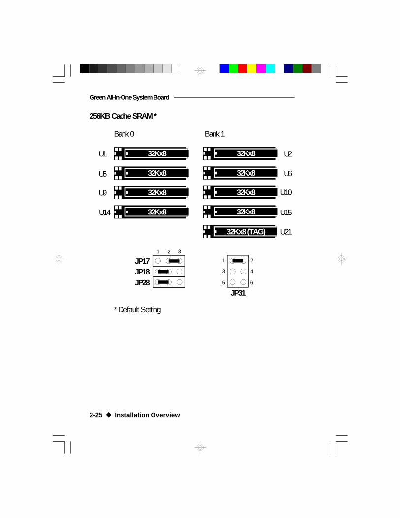
256KB Cache SRAM *
Bank 0
32Kx8
32Kx8
32Kx8
32Kx8U14
U9
U5
U1
Bank 1
1 2 3
JP28JP18JP17 1
3
5
2
4
6
32Kx8 (TAG)
32Kx8
32Kx8
32Kx8
32Kx8
U10
U15
U21
JP31
* Default Setting
U6
U2
G486ESV AIO
Installation Overview u 2-26
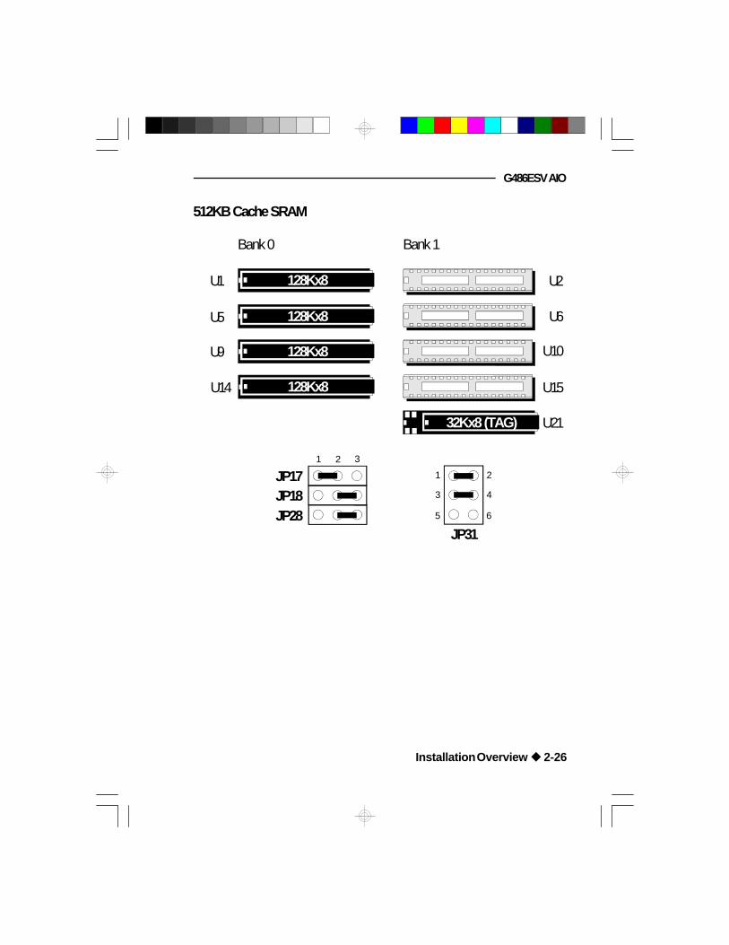
512KB Cache SRAM
Bank 0
U14
U9
U5
U1
32Kx8 (TAG)
Bank 1
U10
U15
U21
1 2 3
JP28JP18JP17 1
3
5
2
4
6
U6
U2
JP31
128Kx8
128Kx8
128Kx8
128Kx8

Green All-In-One System Board
2-27 u Installation Overview
Bank 0
U14
U9
U5
U1
Bank 1
1 2 3
JP28JP18JP17 1
3
5
2
4
6
U10
U15
U21
U6
U2
1MB Cache SRAM
JP31
128Kx8
128Kx8
128Kx8
128Kx8
128Kx8
128Kx8
128Kx8
128Kx8
128Kx8 (TAG)

G486ESV AIO
Installation Overview u 2-28
CPU Installation and UpgradeJumper Settings for CPUs
ISA
Slot
VE
SA
Slot
ZIF Socket
EC100G
Trio64/32
DP83905
JP6JP7 JP8
JP14
JP83
JP53
JP93JP95JP97JP65
JP92
JP74JP75
JP91
JP57
JP58 - JP63
JP55JP38
JP2
JP73
JP94

Green All-In-One System Board
Intel 486SX
JP93
2
1
3
JP94
JP97JP95
JP65
1 2 3
JP60JP59JP58
JP63JP62JP61
1 2 3
JP75JP74
JP91
JP38
JP92
JP8JP7JP6
JP55 JP73
2-29 u Installation Overview
Intel 486SX
1

G486ESV AIO
Note:Make sure Jumper JP53 is set correctly. This jumper isused to select the CPU external clock speed. The exter-nal CPU clock speed of the Intel 486SX CPU is equal toits internal clock speed. Please refer to page 2-45.
Jumper JP57 is used to select the CPU voltage. Makesure it is set correctly. Please refer to page 2-46.
Please refer to page 2-47 of the manual to determinethe appropriate setting for Jumper JP83.
Installation Overview u 2-30

Green All-In-One System Board
Intel 486DX/DX2/DX4
JP93
2
1
3
JP94
JP97JP95
JP65
1 2 3
JP60JP59JP58
JP63JP62JP61
1 2 3
JP75JP74
JP91
JP38
JP92
JP8JP7JP6
JP55 JP73
2-31 u Installation Overview
1
Intel 486DX/DX2/DX4

G486ESV AIO
Installation Overview u 2-32
Note:Make sure Jumper JP53 is set correctly. The externalCPU clock speed of the Intel 486DX CPU is equal to itsinternal clock speed. To get the external CPU clockspeed of the Intel 486DX2 CPU, divide its internal clockspeed by 2. To get the external CPU clock speed of theIntel 486DX4, divide its internal clock speed by 3.Please refer to page 2-45.
Jumper JP57 is used to select the CPU voltage. Makesure it is set correctly. Please refer to page 2-46.
Please refer to page 2-47 of the manual to determinethe appropriate setting for Jumper JP83.

Green All-In-One System Board
AMD Am486DX/DX4
JP93
2
1
3
JP94
JP97JP95
JP65
1 2 3
JP60JP59JP58
JP63JP62JP61
1 2 3
JP75JP74
JP91
JP38
JP92
JP8JP7JP6
JP55 JP73
2-33 u Installation Overview
1
AMD Am486DX/DX4

G486ESV AIO
Note:Make sure Jumper JP53 is set correctly. The externalCPU clock speed of the AMD Am486DX CPU is equalto its internal clock speed. To get the external CPUclock speed of the AMD Am486DX4, divide its internalclock speed by 3. Please refer to page 2-45.
Jumper JP57 is used to select the CPU voltage. Makesure it is set correctly. Please refer to page 2-46.
Please refer to page 2-47 of the manual to determinethe appropriate setting for Jumper JP83.
Installation Overview u 2-34

Green All-In-One System Board
Intel Write-back 486 CPU
JP93
2
1
3
JP94
JP97JP95
JP65
1 2 3
JP60JP59JP58
JP63JP62JP61
1 2 3
JP75JP74
JP91
JP38
JP92
JP8JP7JP6
JP55 JP73
2-35 u Installation Overview
1
Intel Write-back486 CPU

G486ESV AIO
Installation Overview u 2-36
Note:Make sure Jumper JP53 is set correctly. To get theexternal CPU clock speed of the Intel Write-back 486CPU, divide its internal clock speed by 2. Please referto page 2-45.
Jumper JP57 is used to select the CPU voltage. Makesure it is set correctly. Please refer to page 2-46.
Please refer to page 2-47 of the manual to determinethe appropriate setting for Jumper JP83.

Green All-In-One System Board
Intel Pentium OverDrive Processor
JP93
2
1
3
JP94
JP97JP95
JP65
1 2 3
JP60JP59JP58
JP63JP62JP61
1 2 3
JP75JP74
JP91
JP38
JP92
JP8JP7JP6
JP55 JP73
2-37 u Installation Overview
1
Intel PentiumOverDriveProcessor

G486ESV AIO
Installation Overview u 2-38
Note:Make sure Jumper JP53 is set correctly. To get theexternal CPU clock speed of the Pentium OverDriveProcessor, divide its internal clock speed by 2.5. Pleaserefer to page 2-45.
Jumper JP57 is used to select the CPU voltage. Makesure it is set correctly. Please refer to page 2-46.
Please refer to page 2-47 of the manual to determinethe appropriate setting for Jumper JP83.

Green All-In-One System Board
JP93
2
1
3
JP94
JP97JP95
JP65
1 2 3
JP60JP59JP58
JP63JP62JP61
1 2 3
JP75JP74
JP91
JP38
JP92
JP8JP7JP6
JP55 JP73
2-39 u Installation Overview
AMD Am486DX2
1
AMD Am486DX2

G486ESV AIO
Installation Overview u 2-40
Note:Make sure Jumper JP53 is set correctly. To get theexternal CPU clock speed of the AMD Am486DX2,divide its internal clock speed by 2. Please refer to page2-45.
Jumper JP57 is used to select the CPU voltage. Makesure it is set correctly. Please refer to page 2-46.
Please refer to page 2-47 of the manual to determinethe appropriate setting for Jumper JP83.
Green All-In-One System Board
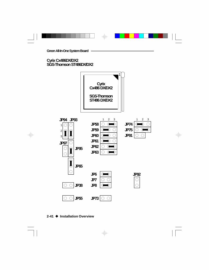
Cyrix Cx486DX/DX2SGS-Thomson ST486DX/DX2
2-41 u Installation Overview
JP93
2
1
3
JP94
JP97JP95
JP65
1 2 3
JP60JP59JP58
JP63JP62JP61
1 2 3
JP75JP74
JP91
JP38
JP92
JP8JP7JP6
JP55 JP73
1
CyrixCx486 DX/DX2
SGS-ThomsonST486 DX/DX2

G486ESV AIO
Note:Make sure Jumper JP53 is set correctly. The externalCPU clock speed of the Cyrix Cx486DX CPU is equalto its internal clock speed. To get the external CPUclock speed of the Cyrix Cx486DX2, divide its internalclock speed by 2. Please refer to page 2-45.
The external CPU clock speed of the SGS-ThomsonST486DX CPU is equal to its internal clock speed. Toget the external CPU clock speed of the SGS-ThomsonST486DX2, divide its internal clock speed by 2. Pleaserefer to page 2-45.
Jumper JP57 is used to select the CPU voltage. Makesure it is set correctly. Please refer to page 2-46.
Please refer to page 2-47 of the manual to determinethe appropriate setting for Jumper JP83.
Installation Overview u 2-42

Green All-In-One System Board
UMC U5 CPUs
JP93
2
1
3
JP94
JP97JP95
JP65
1 2 3
JP60JP59JP58
JP63JP62JP61
1 2 3
JP75JP74
JP91
JP38
JP92
JP8JP7JP6
JP55 JP73
2-43 u Installation Overview
1
UMC U5 CPUs

G486ESV AIO
Installation Overview u 2-44
Note:Make sure Jumper JP53 is set correctly. The externalCPU clock speed of every UMC U5 CPU is equal to itsinternal clock speed. Please refer to page 2-45.
Jumper JP57 is used to select the CPU voltage. Makesure it is set correctly. Please refer to page 2-46.
Please refer to page 2-47 of the manual to determinethe appropriate setting for Jumper JP83.
Green All-In-One System Board
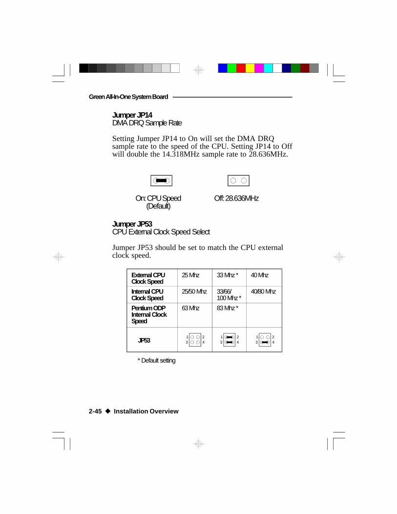
Jumper JP14DMA DRQ Sample Rate
Setting Jumper JP14 to On will set the DMA DRQsample rate to the speed of the CPU. Setting JP14 to Offwill double the 14.318MHz sample rate to 28.636MHz.
On: CPU Speed(Default)
Off: 28.636MHz
Jumper JP53CPU External Clock Speed Select
Jumper JP53 should be set to match the CPU externalclock speed.
2-45 u Installation Overview
Internal CPUClock Speed
External CPUClock Speed
Pentium ODPInternal ClockSpeed
JP53
25 Mhz
25/50 Mhz
63 Mhz
13 4
2
83 Mhz *
33/66/100 Mhz *
33 Mhz *
13 4
2
40 Mhz
40/80 Mhz
13 4
2
* Default setting

G486ESV AIO
Jumper JP57CPU Voltage Select
Set Jumper JP57 according to the voltage of the CPUinstalled in your system board.
5 3 1
6 4 2
Pins 1-3, 2-4 On:5V CPUs(Default)
5 3 1
6 4 2
Pins 3-5, 4-6 On:3.45V CPUs
3.45V CPUs:
AMD -A80486DX4-100NV8TA80486DX2-80NV8TA80486DX2-66NV8T
Cyrix -Cx486DX2-V66GPCx486DX2-V80GPCx486DX2-V50GP
Intel 486 -A80486DX4-100A80486DX4-75
UMC -U5SLV-SUPER25U5SLV-SUPER33
Installation Overview u 2-46
Green All-In-One System Board
2-47 u Installation Overview
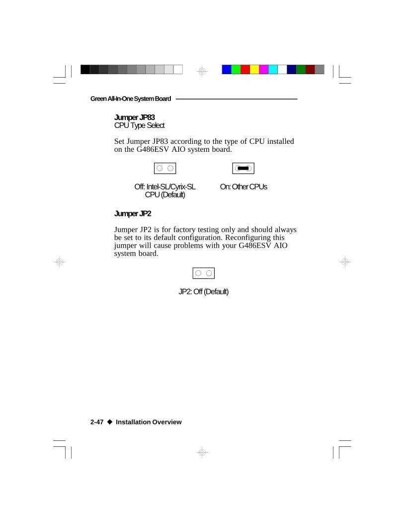
On: Other CPUsOff: Intel-SL/Cyrix-SLCPU (Default)
Jumper JP2
Jumper JP2 is for factory testing only and should alwaysbe set to its default configuration. Reconfiguring thisjumper will cause problems with your G486ESV AIOsystem board.
JP2: Off (Default)
Jumper JP83CPU Type Select
Set Jumper JP83 according to the type of CPU installedon the G486ESV AIO system board.

G486ESV AIO
Installing Upgrade CPUs
The G486ESV AIO is equipped with a 237-pin ZeroInsertion Force (ZIF) socket at location U43 of thesystem board. This socket is designed for easy removalof the old CPU and easy insertion of the upgrade CPU.The socket allows you to carefully place the new CPUinto its position. If you need to apply excessive force toinsert the CPU, the installation is being done incorrectly.
Location of the ZIF Socket on theG486ESV AIO System Board
ZIF Socket
Pin one of the socket
Installation Overview u 2-48

Green All-In-One System Board
Warning:Open the socket only if actually installing a CPU. Thewarranty on the original CPU will be voided if the S/Nseal is broken. Installation of an OverDriveTM Processorwill not affect the original system warranty.
The ZIF socket consists of four rows of pin holes oneach side. Install the 80486SX, 80486DX, 80486DX2 orthe Intel486TM OverDrive Processor, which only hasthree rows of pins, in the three inner rows of the socket.The outermost row of pin holes should be visible on allfour sides of the socket when any of these CPUs isinstalled. The PentiumTM OverDrive Processor has fourrows of pins on each side, and should be installed so itcovers all the pin holes of the ZIF socket.
To avoid improper installation, the ZIF socket isdesigned with a Plug/Keying mechanism. There areseveral holes in the socket that are plugged, so the CPUwill only go in one way. If you are unable to easilyinsert the CPU, please verify pin 1 of the CPU is beingplugged into pin 1 of the socket. The location of pin 1is shown on the next page.
Caution:You will need to change the CPU-type jumper settings.(Please see the previous pages of this manual.)
Before proceeding with the upgrade, take note of thefollowing. The microprocessor and heat sink may be hotif the system has been running. To avoid the possibilityof a burn, power the system off and let the processorand heat sink cool for 10 minutes.
2-49 u Installation Overview

G486ESV AIO
Zero Insertion Force (ZIF) Socket
To install an upgrade CPU, do the following.
1. Make sure the handle on the side of the ZIF socketis up. To raise the handle, push down, pull it out tothe side a little and raise it as far as it will go. Thetop plate will slide back. Do not use screw drivers orother tools to open the socket, or damage may occurto the system or socket. It may be necessary toinitially apply a small amount of sideways force tofree the handle from its retaining “tab.” Once clearof the “tab,” the handle will open relatively easily.
Installation Overview u 2-50

Green All-In-One System Board
Pin 1 of the ZIF Socket
Lifting the Handle
2. Once the lever is completely up, remove the oldCPU by carefully lifting it straight out of the socket.You are now ready to insert the new CPU.
2-51 u Installation Overview

G486ESV AIO
3. Position the CPU above the ZIF socket. Make surepin 1 of the CPU is aligned with pin 1 of the socket.Lower the chip until the pins are inserted properly intheir corresponding holes. Remember that very littleforce is needed to install the CPU. If the CPU willnot easily insert, please verify you have pin 1 of theCPU aligned with pin 1 of the socket. Applying toomuch pressure can damage the CPU or the socket.
Positioning the CPU Above the ZIF Socket
4. Push the handle down until the handle locks intoplace. The top plate will slide forward. You will feelsome resistance as the pressure starts to secure theCPU in the socket. This is normal and will notdamage the CPU. However, if the handle is notcompletely closed, damage to the CPU and/orsystem board may result.
Installation Overview u 2-52

Green All-In-One System Board
Clearance Requirements
The Pentium OverDrive processor comes with a heatsink mounted on top. To maintain proper airflow oncethe upgrade is installed on the system board, theprocessor and heat sink require certain space clearances.
The clearance above the OverDrive processor's fan/heat-sink must be at least 0.4 in. The clearance on at least 3of 4 sides of the processor must be at least 0.2 in. Thecables (for floppy drive, hard drive CD-ROM, etc.) mustbe routed clear of the CPU and its airspace.
Fan Exhaust
The CPU must be kept cool by using a fan exhaustconfiguration in connection with the heatsink. Thetemperature of the air entering the fan/heatsink cannotexceed 45°C.
In order to provide proper airflow to the CPU, allmovable obstructions (power supply cables, cards,floppy disk cables) must be clear of the CPU heatsink/fan component. Please see the clearance requirementsabove for more information.
Note:Verify that Jumper JP57 (CPU Vcc Select) is set tomatch the voltage of your upgrade CPU. Refer to page2-37 for more information.
2-53 u Installation Overview

G486ESV AIO
Upgrading the Video Memory from 1MB to 2MB
If your G486ESV AIO is equipped with 1MB of videomemory, it can be upgraded to 2MB by installing twoadditional 256Kx16 DRAM chips. This will allow 256colors to be simultaneously displayed in the 1280x1024mode. The DRAM speed should be 70ns and we recom-mend using the same brand of chips as those alreadyinstalled. Insert the DRAM chips in the empty DRAMsockets (U53 and U54) on your system board as shownbelow.
U54
U53
Installation Overview u 2-54

Green All-In-One System Board
Installing the Remote Boot ROM
This chapter describes how to install the optional Re-mote Boot ROM. The location of the socket is shownbelow.
The Remote Boot ROM Socket on theG486ESV AIO System Board
Remote BootROM Socket
2-55 u Installation Overview

G486ESV AIO
To ease insertion of the Boot ROM chip into the socket,the pins or legs must be slightly bent. This is done byholding one side of the chip against a flat surface andgently pushing the chip. Be careful not to bend the legstoo much.
When all the pins have been slightly bent, the chip isready for insertion. Align the notch on the Boot ROMwith the notch on the socket as shown below.
BOOT ROM
Before pushing the chip into its socket, make sure thepins are all aligned with the holes in the socket. If a pinis not inserted properly, the boot ROM will not func-tion. Please note, a pin may bend up under the chip andlead you to mistakenly believe it is inserted properly.
Installation Overview u 2-56

Green All-In-One System Board
Installing the System Board
Before installing the system board into your system unit,you should prepare the tools you will use:
You will need:• one medium size, flat-bladed screwdriver• one medium Philips screwdriver• one nutdriver, 3/16" or 5mm• one grounded wriststrap is strongly
recommended to protect the board against staticelectricity discharges.
Step 1
Unlock your system unit. Turn off the power and dis-connect all power cords and cables.
Step 2
Remove the system unit cover. Refer to the manufac-turer's instructions if necessary.
Step 3
Remove expansion cards seated in any of the expansionslots and detach all connectors from the old systemboard.
Step 4
Loosen the screws holding the original system board andremove the board from the system. Save the screws.
2-57 u Installation Overview

G486ESV AIO
Step 5
Insert the HSIM modules into the HSIMM banks on theG486ESV AIO. The quantity and location of the HSIMmodules depend upon the memory configuration andtype of modules you intend to use.
Step 6
Set the appropriate jumpers.
Step 7
Install the prepared G486ESV AIO system board intothe case and replace the screws.
Step 8
If you are using the AUI connector, or the ECT-100,you will have to locate for a free slot at the back of thesystem unit's case to install the additional ports. Whenyou have chosen a suitable slot, remove the screw andthe slot cover. Save the slot cover for future use. Youwill be using the screws in the next step.
Note:The ECT-100 is a card-edge bracket holding the AUI,BNC and RJ-45 connectors.
Step 9
Insert the bracket holding the AUI connector or theECT-100 bracket into the vacant slot. Secure the bracketwith the slot cover screw.
Installation Overview u 2-58

Green All-In-One System Board
Step 10
Reinstall all cards and replace the system unit cover.
Step 11
Plug in any peripherals, such as a mouse, modem orprinter, into the appropriate ports on the G486ESV AIOboard. Reconnect all power cords and cables.
2-59 u Installation Overview

G486ESV AIO
Built-in Ports
The G486ESV AIO system board is equipped with twoserial ports, one EPP parallel printer port, one FDDconnector, one IDE hard disk interface, one BNC con-nector, one RJ-45 connector, one AUI connector, oneanalog connector, one feature connector, one PS/2mouse port and one PS/2 keyboard connector. Thechapter, “Initial Setup Program”, describes the softwaresetup procedures of these functions.
J3LANExtra
J5AUI
Connector
J4Floppy Disk
DriveConnector
J2IDE HDDConnector
AnalogConnector
ParallelPrinterPort
COM2 COM1
J13 Feature Connector
CN6 CN5 CN4 CN3 J6
CN
1
KB
1
BNCConnector
CN2RJ-45Connector
PS/2KeyboardConnector
PS/2 MousePort
Installation Overview u 2-60

Green All-In-One System Board
Serial Ports
The built-in primary (COM1) and secondary (COM2)serial ports are RS-232C asynchronous communicationports that can be used with modems, serial printers,remote display terminals, and other serial devices. Theseserial ports use the following system I/O addresses:
Connecting the Serial Ports
The primary serial port (COM1) and secondary serialport (COM2) are 9-pin connectors on the system board.Connect the serial port cable to Connector CN3 for theCOM1 primary serial port and the other serial port cableto Connector CN4 for the COM2 secondary serial port.Make sure the colored stripes on the ribbon cables alignwith pin 1 of Connectors CN3 and CN4.
Port Configuration I/O Address
COM1 3F8hCOM2 2F8h
COM3/COM4 220h/228h, 2E8h/2E0h,3E8h/2E8h or 338h/238h
2-61 u Installation Overview

G486ESV AIO
Parallel Port
The G486ESV AIO system board has a standard con-nector for interfacing your PC to a parallel printer. Thisport is compatible with both IBM AT printer ports andthe new, high speed, bi-directional Enhanced ParallelPort standard. The parallel port on your system boardcan be set to any of the following system I/O addresses:
Port Configuration I/O Address
LPT1 3BC-3BE HexLPT2 378-37F HexLPT3 278-27F Hex
Floppy Disk Drive Connector
The G486ESV AIO system board has a built-in floppydisk controller that supports two standard floppy diskdrives. You can install any 360KB/720KB/1.2MB/1.44MB/2.88MB floppy disk drives.
Installation Overview u 2-62

Green All-In-One System Board
Connecting the Floppy Disk Cable
The Floppy Disk Connector on theG486ESV AIO System Board
Step 1Install the 34-pin header connector into the floppy diskconnector (J4) on the G486ESV AIO system board, withthe colored edge of the ribbon aligned to pin 1.
Step 2Install the other 34-pin header connector(s) into the diskdrive(s), with the colored edge of the daisy chainedribbon cable aligned to pin 1 of the drive edgeconnector(s). The end-most connector should be at-tached to the drive you want to be Drive A.
Pin 1Stripe
2-63 u Installation Overview

G486ESV AIO
Pin 1 Stripe
IDE Hard Disk Connector
The G486ESV AIO system board will interface two IDE(Integrated Drive Electronics) hard disk drives. An IDEdrive is a hard drive with the controller electronics builtinto the disk assembly. The integration of the controllerand the drive as a single unit increases both the reliabil-ity and performance by eliminating redundant circuitry.
Note:Only IDE drives can be connected to the IDE interface.
Connecting the IDE Hard Disk interface
The IDE Hard Disk Connector on theG486ESV AIO System Board
Installation Overview u 2-64

Green All-In-One System Board
Step 1Install the 40-pin header connector into the hard diskconnector (J2) on the G486ESV AIO system board, withthe colored edge of the ribbon aligned to pin 1.
Step 2Install the other 40-pin header connector(s) into the diskdrive(s), with the colored edge of the daisy chainedribbon cable aligned to pin 1 of the drive edgeconnector(s). The end-most connector should be at-tached to the drive you want to be Drive C.
Note:Refer to your disk drive user's manual for informationabout selecting proper drive switch settings.
Adding a Second IDE Hard Drive
When using two IDE drives, one must be set as themaster and the other as the slave. Follow the instruc-tions provided by the drive manufacturer for setting thejumpers and/or switches on the drives. No changes areneeded on the G486ESV AIO system board whenadding a second hard drive.
We recommend that both IDE hard drives be from thesame manufacturer. In a few cases, drives from twomanufacturers will not function properly when usedtogether. The problem lies in the two drives, not theG486ESV AIO system board.
Preparing an IDE Drive for Use
IDE disk drives are already low-level formatted, withany bad-track errors entered, when shipped by the drivemanufacturer. Do not attempt to do a low-level format,or you may cause serious damage to the drive.
2-65 u Installation Overview

G486ESV AIO
To use an IDE drive, you need to enter the drive type(this information is provided by the drive manufacturer)into the system's CMOS setup table. Then run FDISKand FORMAT provided with DOS.
Note:Do not run FDISK and FORMAT on a drive that hasalready been formatted, or you will lose all programsand data stored on the drive.
PS/2 Mouse Port
A 6-pin PS/2 mouse port is built-in to theG486ESV AIO system board. Connect your PS/2mouse to Connector J6 on the system board.
Analog Connector
The G486ESV AIO system board is equipped with abuilt-in 15-pin VGA analog connector that supports1280x1024 graphics resolution in 256 colors with 2MBof maximum video memory onboard. It supports hori-zontal sync and vertical sync for VESA Display Ad-vanced Power Management (DAPM) compliant moni-tors.
Connecting the Analog Connector
The G486ESV AIO system board can only be used withan analog video display using a 15-pin D-shell cableconnector (standard VGA monitor connection). If yourmonitor supports analog video, but does not have a15-pin D-shell connector, see your monitor dealer for anadapter or optional cable.
Installation Overview u 2-66

Green All-In-One System Board
Insert the VGA monitor video connector into the 15-pinVGA analog connector on the G486ESV AIO systemboard and plug the VGA monitor power cord into agrounded three-pronged power outlet. Refer to yourmonitor reference manual for more information.
Note:Some monitors have a switch that chooses betweenanalog and TTL (or digital) operation. If your monitorhas such a switch, set it for analog operation.
AUI Connector
The G486ESV AIO supports an AUI connector. TheAUI connector is a 15-pin connector attached to aribbon cable. Attach the ribbon cable, which came withthe G486ESV AIO, to connector J5 on the systemboard. Make sure the colored stripe on the ribbon cablealigns with pin 1 of connector J5 as shown below.
The AUI Connector on the G486ESV AIO System Board
AUI Connector
2-67 u Installation Overview

G486ESV AIO
Ethernet Cable
Use RG-11 Ethernet cable and the 15-pin AUI connec-tor for standard Ethernet installation.
Connect the station end of the transceiver cable to theAUI connector of the G486ESV AIO system board.Tighten the screws on the adapter plate. Be careful notto tighten them too much. Connect the other end of thetransceiver cable to the transceiver box.
To connect one station to another, RG-11 thick trunkcable must be connected from one station's transceiverbox to another station's transceiver box.
Connecting a Transceiver Cable to theG486ESV AIO System Board
AUI Connector
Transceiver Cable
Installation Overview u 2-68

Green All-In-One System Board
BNC Connector
The G486ESV AIO supports an optional BNC connec-tor at location CN1 of the system board.
Cheapernet Cable
Use RG-58 A/U thin Ethernet cable and the BNCconnector for Cheapernet installation.
To connect a BNC T-connector to the BNC connector ofthe G486ESV AIO system board, align the post of theBNC connector with the slot of the BNCT-connector. Push the T-connector into the BNC con-nector and twist the T-connector sleeve clockwise as faras it will go.
Connect the RG-58 cable to one end of the BNCT-connector. To hook one station to another, connectRG-58 cable from one-end of the T-connector to oneend of the T-connector of the next system.
Connecting a BNC T-Connector to the G486ECV-AIO
BNC Connector
BNCT-Connector
Cheapernet Cable
2-69 u Installation Overview

G486ESV AIO
Twisted-Pair Connector
The G486ESV AIO supports an optional RJ-45 connec-tor at location CN2 of the system board.
Twisted-Pair Cable
Use twisted-pair cable and the RJ-45 modular phonejack connector for Twisted-Pair installation.
Twisted-Pair installation is done by connecting themodular connector of the twisted-pair cable to the RJ-45modular phone jack connector of the G486ESV AIOsystem board.
Each station in the network is connected to a port on ahub. This type of installation is favorable, since onestation can go down without affecting the rest of thenetwork.
Connecting a Modular Connectorto the G486ESV AIO System Board
RJ-45 Connector
Modular ConnectorTwisted-Pair Cable
Installation Overview u 2-70

Green All-In-One System Board
J5
J3
J2
J1 BNC ConnectorAUI Connector
RJ-45 Connector
ECT-100
If your G486ESV AIO system board is not equippedwith a BNC or RJ-45 connector, an optional ECT-100will be provided upon request.The ECT-100 is a card-edge metal bracket holding the AUI, BNC and RJ-45connectors.
Step 1Attach the ribbon cable connected to J1 of the ECT-100 toconnector J5 (AUI Connector) on the G486ESV AIOboard, with the colored edge of the ribbon aligned to pin 1.
Step 2Attach the ribbon cable connected to J2 of the ECT-100 toconnector J3 (LAN Extra) on the G486ESV AIO board,with the colored edge of the ribbon aligned to pin 1.
Connecting the ECT-100 to the G486ESV AIO System Board
2-71 u Installation Overview

G486ESV AIO
v Initial Setup ProgramAfter you power up your system, the BIOS messageappears on your screen and the memory count begins.
After the memory test, the following message willappear on the screen:
Press CTRL-ALT-ESC/DEL to enter setup
If the message disappears before you respond, restartyour system or press the “Reset” button. You may alsorestart the system by pressing the <Ctrl> <Alt> <Del>keys. If you do not press these keys at the correct timeand the system does not boot, the following error mes-sage will appear:
Press F1 to continue or Del to enter Setup
If you have set a password and selected “System” in theSecurity Option of the BIOS Feature Setup menu, youwill be prompted for the password everytime the systemis rebooted or any time you try to enter Setup. Type inthe correct password and press <Enter>.
If you selected “Setup” in the Security Option, you willbe prompted for the password only when you try toenter Setup. Refer to the “BIOS Features Setup” sectionfor more information.
Award BIOS CMOS Setup Utility
Press <Ctrl> <Alt> <Esc> or <Del> to enter the Setuputility. A screen similar to the one on the next page willappear.
Initial Setup Program u 3-1

Green All-In-One System Board
Use the arrow keys to highlight the option you want andpress <Enter>.
Standard CMOS Setup
Use the arrow keys to highlight “Standard CMOSSetup” and press <Enter>, a screen similar to the onebelow will appear.
3-2 u Initial Setup Program

G486ESV AIO
Date and TimeSets the time and date for the system. Press <F3> forthe calendar.
Drive C and Drive DIf you have added a hard drive, you must select theappropriate type for the drive. The G486ESV AIO has46 pre-set types and one user-definable type. Use the<Page Up> or <Page Down> keys to select the appropri-ate type for the drive.
The table in Appendix G gives a complete listing of theavailable drive types. Any given hard drive must be setto one specific drive-type number. Please refer to yourhard drive documentation to find the appropriate typenumber.
If none of the pre-set types is appropriate for your harddrive, choose “User,” which is the user-definable type.To use this type, highlight either hard disk C or D,depending on your hard drive configuration. Use thearrow keys until type “User” is showing.
You might want to use the “IDE HDD Auto Detection”option to set the appropriate type for your drive. Referto page 3-12 of this manual.
Fill in all the parameters as specified by the drivemanufacturer. If either of the drives is not present, select“None” and press <Enter>.
Drive A and Drive BThese options are used to select the type of floppy diskdrives installed in your system. If either of the drives isnot present, select “None.” Make sure you choose thecorrect drive type; otherwise, your system might im-properly format the device.
Initial Setup Program u 3-3

Green All-In-One System Board
VideoThis is used to select the type of video adapter installedin your system.
Halt onThis option selects when the system will halt if an erroris detected during power up.
No Errors: The system boot will not stop for anyerrors detected.
All Errors: The system will stop whenever the BIOSdetects a non-fatal error.
All, But Keyboard: The system will stop for anyerrors except a keyboard error.
All, But Diskette: The system will stop for anyerrors except a disk error.
All, But Disk/Key: The system will stop for anyerrors except a keyboard or diskerror.
MemoryThe lower right hand corner shows the base memorysize, extended memory size, and the other memory sizeof your system. You cannot alter these items; yourcomputer automatically detects and displays them.
The Other Memory size refers to the memory located inthe 640K to 1024K address space. This is the memoryused for different applications. DOS uses this area toload device drivers to maximize free base memory forapplication programs. Most use this for the ShadowRAM.
3-4 u Initial Setup Program

G486ESV AIO
BIOS Features Setup
Use the arrow keys to highlight “BIOS Features Setup”and press <Enter>; a screen similar to the one belowwill appear.
The Virus Warning option may be set to “enabled” or“disabled.” When enabled, the BIOS issues a warningwhen any program or virus sends a Disk Format com-mand or attempts to write to the boot sector of the harddisk drive.
If you choose “System” in the Security Option, you willbe prompted for a password every time you cold bootyour system or access setup. If you choose “Setup,” youwill be prompted for a password only when trying toaccess setup.
If the changes you made are incorrect or you changeyour mind, press <F6> or <F7> to return to the defaultsettings. Press <Esc> after making the changes to returnto the main menu.
Initial Setup Program u 3-5

Green All-In-One System Board
Chipset Features Setup
The G486ESV AIO uses the EFAR EC802G chipset.The Chipset Features Setup allows you to modify somefunctions to optimize system performance.
If you press <Enter>, a screen similar to the one belowwill appear.
If the Auto Configuration option is set to “Enabled,”the Cache write wait state, External cache burst read,DRAM R/W wait state, and AT bus clock selectionoptions will automatically be set to their maximum(fastest) values. However, if the G486ESV AIO systemboard becomes unstable, set the Auto Configurationoption to “Disabled”. This will allow you to reset theseoptions to a slower value.
The Chipset Features Setup option also allows you toenable or disable the onboard serial ports, parallel port,floppy disk controller and hard disk controller.
3-6 u Initial Setup Program

G486ESV AIO
Use the arrow keys to move the highlight bar to theoption you wish to change or modify. Use the <PageUp>, <Page Down>, <+> or <-> keys to make thecorresponding changes.
If the changes you made are incorrect or you changeyour mind, press <F6> or <F7> to return to the defaultsettings. Press <Esc> after making the changes to returnto the main menu.
Power Management Setup
Use the arrow keys to highlight “Power ManagementSetup” and press <Enter>, a screen similar to the onebelow will appear.
Choosing “User Defined” in the Power Managementoption will allow you to set the time of the powermanagement features. “Min Power Saving” and “MaxPower Saving” will set the minimum and maximumvalue of these options respectively. Choose “Disabled”if you do not wish your system to enter the green mode.
Initial Setup Program u 3-7

Green All-In-One System Board
Enabling the DMA request check, Interrupt check,Parallel port check, Serial port check, Hard disk checkor Video write check will allow your system to enter thegreen mode and resume anytime there is an interruptgenerated from these ports. If any of these options is setto “Disabled,” the system will enter the green mode, butwill not resume operation, even if there is an interruptgenerated from these ports, unless you press any key onthe keyboard or move the mouse.
where:
P-Event Primary EventS-Event Secondary EventSB-Timer Standby TimerSP-Timer Suspend TimerI-Timer Intermediate Timer
The gray arrows and circle indicate optional state andstate transitions.
3-8 u Initial Setup Program

G486ESV AIO
Standby Mode TimerThe system will go into Standby Mode after the systemis inactive for the duration set in this timer. In StandbyMode, the system conserves power by slowing the CPUto an intermediate speed, which you can define in theStandby Mode Speed entry.
Suspend Mode TimerAfter the system enters Standby Mode, the system willgo into Suspend Mode after the system is inactive forthe duration set in this timer. You can prolong operationof the system in Standby Mode by defining secondaryevents. Secondary events are defined using the EventClass fields on the right side of this setup screen. If asecondary event occurs while the Suspend Timer iscounting, the Suspend counter starts from the beginningagain.
In Suspend Mode, the system conserves power byslowing the CPU to the speed set in the Suspend ModeSpeed entry. In Suspend Mode, the system also blanksthe screen. Suspend Mode gives greater power savingsthan Standby Mode.
Video Standby TimerThe monitor screen will go blank after the system isinactive for the duration set in this timer. In the VideoOff Method field, you can specify how the screen isblanked. Greatest power savings are achieved if youselect the “V/H SYNC+Blank” selection.
HDD Standby TimerThe hard disk drive motor will stop spinning after theduration set in this timer. Most current-model IDE harddrives support this feature.
Initial Setup Program u 3-9

Green All-In-One System Board
Intermediate TimerWhen the system is in Standby Mode, it will be set intoIntermediate Mode by a secondary event. After theIntermediate Timer runs out, the system will return toStandby Mode. The Standby Mode timer will startcounting from the beginning. Secondary events allowyou to run your system at the intermediate StandbyMode speed.
IRQ5-15 Event Class, Video Write ClassPrimary events will set the system into Ready Mode forfull-speed operation. If the system is in intermediate-speed Standby Mode, secondary events will prolongoperation in Standby Mode.
Load BIOS Defaults
If, for some reason, the CMOS becomes corrupted, thesystem can be reconfigured with the default valuesstored in the ROM chips. The BIOS default valuesprovide the slowest performance for the system. Youshould use these values only if you are having hardwareproblems.
Highlight this option on the main menu and press<Enter>. The message below will appear.
Load BIOS Defaults (Y/N)? N
Type “Y” and press <Enter> to return to the BIOS setupdefault values. After pressing <Enter>, you will bereturned to the main menu.
3-10 u Initial Setup Program

G486ESV AIO
Initial Setup Program u 3-11
Load Setup Defaults
The Setup default values are very stable and should beselected as standard values for your system. Highlightthis option on the main menu and press <Enter>. Themessage below will appear.
Load Setup Defaults (Y/N)? N
Type “Y” and press <Enter> to return to the Setupdefault values. After pressing <Enter>, you will bereturned to the main menu.
To configure your system for optimum performance,you must reset the options under the Chipset Featuressetup. You are advised to do so only under the instruc-tion of a technical engineer, otherwise, failure mayoccur.
Password Setting
If you want to set a password, make sure the SecurityOption under the BIOS Features Setup is set to “Sys-tem” or “Setup”. Refer to the BIOS Features Setupoption for more information.
Use the arrow keys to highlight the Password Settingoption and press <Enter>. The message below willappear.
Enter Password:
Type in the password. You are limited to eight charac-ters. Type in a password that is eight characters long orshorter. When done, the following message will appear:
Confirm Password:

Green All-In-One System Board
You are asked to verify the password. Type in exactlythe same password. If you type in a wrong password,you will be prompted to enter the correct passwordagain. Otherwise, enter a new password.
To delete or disable the password function, simply press<Enter> instead of typing in a new password. If forsome reason, you forget your password, a jumper can beset to clear the password. Refer to Jumper JP5 under theJumper Settings section for more information.
Press the <Esc> key to return to the main menu.
IDE HDD Auto Detection
This option detects the hard disk parameters for the harddisk drives installed in your system. Highlight thisoption and press <Enter>. A screen similar to the onebelow will appear.
3-12 u Initial Setup Program

G486ESV AIO
The screen displays the parameters detected and allowsyou to accept or reject the parameters. Type “Y” andpress <Enter> to accept the parameters, or press <Esc>to abort. If you select “Y”, the parameters of the harddisk will be displayed in the Standard CMOS Setup.
HDD Low Level Format
This option will format, set the interleave mode and doa media analysis of your hard drives. Highlight thisoption and press <Enter>. A screen similar to the onebelow will appear.
Warning:Do not attempt to do a low-level format on an IDEdrive, or you may cause serious damage to the drive.IDE disk drives are already low-level formatted, withany bad-track errors entered, when shipped by the drivemanufacturer.
Use the arrow keys to select an option and press <En-
Initial Setup Program u 3-13

Green All-In-One System Board
ter> to accept the option. Press <Esc> when done.Save & Exit Setup
When all the changes have been made, highlight “Save& Exit Setup” and press <Enter>. The message belowwill appear:
Save to CMOS and Exit (Y/N)? N
Type “Y” and press <Enter>. The following messagewill appear:
Reboot System (Y/N)? N
Type “Y” and press <Enter>. The modifications youhave made will be written into the CMOS memory, andthe system will reboot. You will once again see theinitial diagnostics on the screen. If you wish to makeadditional changes to the setup, press <Ctrl> <Alt><Esc> or <Del> after memory testing is done.
Exit Without Saving
When you do not want to save the changes you havemade, highlight this option and press <Enter>. Themessage below will appear:
Quit Without Saving (Y/N)? N
Type “Y” and press <Enter>. The system will rebootand you will once again see the initial diagnostics on thescreen. If you wish to make any changes to the setup,press <Ctrl> <Alt> <Esc> or <Del> after memorytesting is done.
3-14 u Initial Setup Program

G486ESV AIO
v Setmode Configuration UtilityThe G486ESV AIO board supports optional AUI, BNCand RJ-45 connectors built onto the system board. Theonboard LAN may be configured using either theSetmode Configuration Utility or the Command Lineunder DOS. This allows easy configuration of its portand address settings, without the use of jumpers.
Setmode
Setmode allows you to configure the onboard LAN's I/Oport, IRQ channel, architecture, memory address, andperform a loopback test. The utility also allows you toview the current values in configuration registers A andB.
To run the Setmode utility:
Insert the “NET-700EC/ET/ECT Drivers and Utilities”diskette 1 into drive A: (or B:) and type the followingcommand:
A:\>CD Setmode <Enter>A:\Setmode>Setmode <Enter>
A screen similar to the one on the next page will appear.
Setmode Configuration Utility u 4-1

Green All-In One System Board
Main Functions Menu
“Main Functions” consists of six menus that will helpyou configure the G486ESV AIO's onboard LAN. Payspecial attention to the “Notes” and “Warnings” men-tioned in this section of the manual. They contain impor-tant information that can be the difference between asuccessful and unsuccessful configuration.
Configure Currently Enabled Card
The “Configure Currently Enabled Card” menu allowsyou to configure or change the configuration of theonboard LAN.
Use the arrow keys to move to this menu and press<Enter>, or simply press the function key <F1>. Ascreen similar to the one on the next page will appear.
4-2 u Setmode Configuration Utility
G486ESV AIO
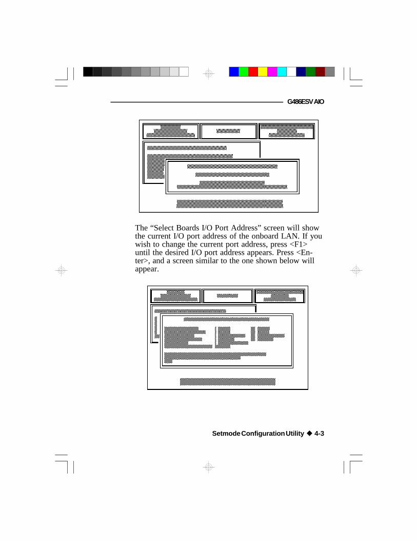
The “Select Boards I/O Port Address” screen will showthe current I/O port address of the onboard LAN. If youwish to change the current port address, press <F1>until the desired I/O port address appears. Press <En-ter>, and a screen similar to the one shown below willappear.
Setmode Configuration Utility u 4-3

Green All-In One System Board
Note:If the message, “No board was present at this address”,appears on the screen, check the following:
1. The address you have selected may not be available.Select another address.
If you wish to view the current address, run theGetmode utility. Refer to the “Getmode” sectionfor more information.
2. If you have selected all of the available addressesand you still get the same message, the onboardLAN may have been disabled. Enable it by usingthe "Configure Card From Disabled Card" menu.Refer to page 4-11 for more information.
You may also use Jumper JP90 to enable theonboard LAN. Refer to page 2-19 for moreinformation.
The “DFI NET-700 Change Configuration” screenallows you to change the configuration of the onboardLAN. Displayed on the screen are the default values forthe I/O Base Address, Interrupt Assignment, PhysicalMedia and Board Architecture. It also includes the“Boot PROM” and “Advanced Configuration” options.
Unless you know of any conflicts with these defaultsettings, configure the onboard LAN with these valuesby selecting the “Update Registers & Save Configurationto EEPROM” option (refer to page 4-10 for moreinformation).
4-4 u Setmode Configuration Utility

G486ESV AIO
If you wish to reconfigure the onboard LAN, use thearrow keys to select the desired option, then press<Enter>.
If your system is installed with a printer port and youronboard LAN is configured under Shared Memorymode, do not choose I/O port 0x360. Under SharedMemory mode, I/O port 0x360 conflicts with the printerport. If you have accidentally chosen 0x360, the onboardLAN will automatically be configured to 0x2C0.
The following steps will show you how to reconfigurethe onboard LAN to another I/O port address.
1. Power off your system and turn it on again.
2. Run the Setmode Configuration Utility.
3. Choose the “Configure Currently Enabled Card”menu.
4. The “Select Board I/O Port Address” screen willappear. Press <F1> to select address 0x2C0. Press<Enter>.
Important:You can only reconfigure the onboard LAN toanother port address if you select 0x2C0 first.
5. The “DFI NET-700 Change Configuration” screenwill appear. Use the arrow keys to select the “I/OBase Address” option and press <Enter> to selectthe appropriate port address.
Setmode Configuration Utility u 4-5

Green All-In One System Board
6. Choose “Update Registers & Save Configuration toEEPROM” to save the newly configured values toEEPROM.
The first four options in the “DFI NET-700 ChangeConfiguration” screen appear in two sets of values, the“current values” and the “new values” (displayed on therightmost column of the screen). Each “new value”changes as you press <Enter>. Continue pressing<Enter> until the desired value appears on the screen.
I/O Base Address
The onboard LAN of your G486ESV AIO board sup-ports the following I/O base addresses: 0x240, 0x280,0x2C0, 0x300, 0x320, 0x340 and 0x360.
This option also allows you to set the onboard LAN toits “Disabled” mode. Under this mode, the onboard LANdoes not appear in any I/O port address, avoiding con-flicts with any add-on board installed in your system. Toenable the onboard LAN, refer to the section “ConfigureCard from Disabled Card” on page 4-11 or Jumper JP90on page 2-19.
Interrupt Assignment
You may configure the onboard LAN to the followinginterrupt request lines: IRQ3-IRQ5, IRQ9-IRQ12 andIRQ15.
4-6 u Setmode Configuration Utility

G486ESV AIO
Physical Media
The onboard LAN of your G486ESV AIO board sup-ports the following physical layer interface: Thin Ether-net, Thick Ethernet, TPI (10BaseT) and TPI (non spec.).
Board Architecture
The onboard LAN can function in two different modes,I/O mode (NE-2000 compatible) and Shared Memorymode (Western Digital/SMC compatible).
Boot PROM
The default setting is “No Boot PROM”. If you have aBoot PROM installed on your G486ESV AIO board,you must alter the setting to the size of the Boot PROMused.
Use the arrow keys to move to the “Boot PROM”option and press <Enter>. A “Boot PROM Select” boxsimilar to the one shown below will appear.
Setmode Configuration Utility u 4-7

Green All-In One System Board
If an 8/16 PROM is installed in the Boot PROM socket,use the arrow keys to select the “Boot PROM with Size8/16K” option and press <Enter>. A “Boot PROMAddress” box similar to the one shown below willappear.
On the other hand, if a 32K PROM is installed, selectthe “Boot PROM with Size 32K” option and press<Enter>. A “Boot PROM Address” box similar to theone shown below will appear.
4-8 u Setmode Configuration Utility

G486ESV AIO
Use the arrow keys to select the appropriate BootPROM address and press <Enter>. The last line on thebox will display the address you have selected. Select“Return to Previous Menu” or press <Esc> to return tothe “DFI NET-700 Change Configuration” screen.
Advanced Configuration
Use the arrow keys to move to this option and press<Enter>. A screen similar to the one shown below willappear.
The “DFI NET-700 Register Flags” screen displays thedefault settings of the available options. Only alter thesettings of the first three options if you encounter acompatibility problem.
Setmode Configuration Utility u 4-9

Green All-In One System Board
The fourth option, TPI Link Integrity Checking Enabled,will allow you to check the linkage between the sendand receive twisted-pair lines, and ensure properfunction.
Use the arrow keys to move to the desired option andpress <Enter> to make the appropriate selections.
Pressing “Return to Previous Menu” or <Esc> willreturn you to the “DFI NET-700 Change Configuration”screen.
Update Registers & Save Configuration to EEPROM
If you choose this option, the configuration you havemodified will be updated. It will also save the newlyconfigured values to the EEPROM, so that when youreboot your system, the onboard LAN will initialize withthese new configurations.
Warning:Only write to the EEPROM after you have successfullypassed the initialization and loopback test. Refer to thesection “Initialize Board and Perform Loopback Test”on page 4-14.
Update Registers to New Configurations
If you choose this option, the configuration you havemodified will be updated. However, the newconfiguration will not be saved to the EEPROM.Therefore, if you reboot your system, the onboard LANwill initialize using the old configuration.
4-10 u Setmode Configuration Utility
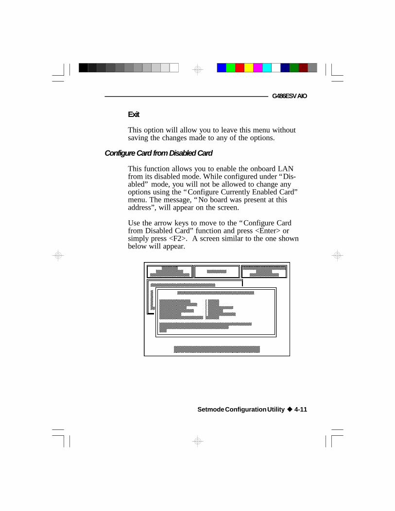
G486ESV AIO
Exit
This option will allow you to leave this menu withoutsaving the changes made to any of the options.
Configure Card from Disabled Card
This function allows you to enable the onboard LANfrom its disabled mode. While configured under “Dis-abled” mode, you will not be allowed to change anyoptions using the “Configure Currently Enabled Card”menu. The message, “No board was present at thisaddress”, will appear on the screen.
Use the arrow keys to move to the “Configure Cardfrom Disabled Card” function and press <Enter> orsimply press <F2>. A screen similar to the one shownbelow will appear.
Setmode Configuration Utility u 4-11

Green All-In One System Board
This function is identical in operation to the “ConfigureCurrently Enabled Card” menu. The only difference isthat the “current values” are not displayed on the screen.
After setting the appropriate options, use the arrow keysto move to the “Update Registers & Save Configurationto EEPROM” option and press <Enter>. The message,“Board Enabled Correctly”, will appear on the screen.
The Setmode Configuration Utility allows you to enablethe onboard LAN once. If you have disabled theonboard LAN for the second time, you must reboot yoursystem first to enable it.
Note:If the onboard LAN was enabled to an address thatconflicts with a device in the system, the error message,“No board was present at this address”, will appear.You must reconfigure the onboard LAN to its correctvalues.
Read the Configuration Registers
This menu displays the current values of ConfigurationRegisters A and B, Shared Memory Control Registers 1and 2, and AT Detect Register. If your onboard LAN isconfigured under I/O mode, you may ignore the valuesof the second and third options. Use the arrow keys tomove to this function and press <Enter>, or simply press<F3>. A screen similar to the one on the next page willappear.
4-12 u Setmode Configuration Utility

G486ESV AIO
Set Shared Memory Addresses
This menu is only accessible when the architecture isconfigured to “Shared Memory” mode. You mustspecify the address of the buffer memory space underthis mode.
Use the arrow keys to move to this function and press<Enter>, or simply press <F4>. A “Shared MemoryAddress” screen similar to the following will appear.
Setmode Configuration Utility u 4-13

Green All-In One System Board
Type the value on the space opposite the “MemoryAddress Value” and press <Esc> to return to the mainmenu.
Initialize Board and Perform Loopback Test
This menu performs initialization and loopback tests ofthe onboard LAN. Use the arrow keys to move to thisfunction and press <Enter>, or simply press <F5>. Ascreen similar to the following one will appear.
Failure to pass any of these tests will require you tocheck the configuration again for any conflicts. This testmust be completed without any errors for the onboardLAN to function properly.
Press <Esc> to return to the main menu.
4-14 u Setmode Configuration Utility

G486ESV AIO
Quit and Return to DOS
Selecting this menu will return you to DOS. Use thearrow keys to move to this function and press <Enter>,or simply press <F10>. A screen similar to the oneshown below will appear. Press “X” to exit or “C” tocontinue.
Configuring via the Command Line
The user may, via the command line, select part of aparticular hardware configuration as shown below:
Setmode [hardware {io_mode I shared_memory} ][input {text} ] [speedy {fast I slow} ][nocablesearch]
Each of the command line options consists of a keywordfollowed by a parameter, except “nocablesearch”, whichsimply disables the automatic cable type select procedurenormally done on initialization.
Setmode Configuration Utility u 4-15

Green All-In One System Board
The command line options may be placed in anenvironment variable named “ETHER”. The environmentvariable is treated exactly like a command line argument.In addition, the Setmode program has built-in defaultsfor all of the command line arguments. The priority ofspecifying the options for each method are shown below.
lowest built-in default environment variablehighest changes during execution
A brief description of each option keyword is givenbelow.
hardware { shared_memory I io_mode }:
Controls a particular hardware configuration wherethe onboard LAN of your G486ESV AIO systemboard will operate. The default hardwareconfiguration is “io_mode”.
input { text }:
Controls the initial input to the program. The textconsists of characters to be initially entered beforereading the characters from the keyboard. This allowsthe program to run through an initial set of menusand stop at the particular menu in which the user isinterested. The text is composed of the characters youwould enter to run the program through the menus.In addition to straight text, the following list ofescape codes are also valid:
4-16 u Setmode Configuration Utility

G486ESV AIO
\r is equivalent to pressing return\n is equivalent to pressing return\e is equivalent to pressing <esc>\dx causes a short delay (software loop),
“x” is a number between 0 and 9\sx causes the input to proceed slowly (software
loop),“x” is a number between 0 and 9
speedy { fast I slow }:
Controls the speed of the video updates for a CGAcontroller. If a CGA controller is used, then Fastmode may produce snow on the screen. Default is setto Fast mode.
nocablesearch:
This option stops the software from automaticallyselecting the cable type to be used. The default isconfigured to automatically select the cable type oninitialization. “Nocablesearch” must be used when theonboard LAN is set to non-software configurable.
Basic Menu and Keyboard Operation
The G486ESV AIO program is controlled by functionkeys. The simple data entry menu is NIC (NetworkInterface Card) shared memory addresses and theoperation of the function keys are displayed in thismenu. The following keys have special meaning:
Setmode Configuration Utility u 4-17

Green All-In One System Board
BACKSPACE erases the most recently enteredcharacter
CONTROL-X erases the entire inputENTER completes the data entry
Getmode
“Getmode” will allow you to view the configuration ofthe onboard LAN, including its Architecture,I/O Base Address, IRQ Channel and Physical LayerInterface, without having to run the Setmode Configura-tion Utility.
To view:
Insert the “NET-700EC/ET/ECT Drivers and Utilities”diskette 1 into drive A: (or B:) and type the followingcommands that appear in bold face type:
A:\>CD GETMODE <Enter>A:\GETMODE>GETMODE <Enter>
A screen similar to the following one will appear.
4-18 u Setmode Configuration Utility
G486ESV AIO
The G486ESV AIO board is designed to be 100%hardware compatible with Novell's NE-2000,NE-2000+ and Western Digital/SMC's Ethercard Plus 16(8013EBT).
Included with the G486ESV AIO board are two LANsoftware driver diskettes. The “NET-700EC/ET/ECTDrivers and Utilities” diskette 1 is for the followingnetwork operating systems: Novell Netware 2.x andNetware 3.x, Packet Driver, and Microsoft's LANManager and Windows for Workgroups. These driversare installed in different directories and subdirectories ofthe diskette. The “NET-700EC/ET/ECT Drivers andUtilities for SCO UNIX” diskette 2 contains the SCOUNIX Streams driver. Refer to Appendix H, whichdetails the file structure of the driver diskettes, to findthe specific driver you need.
Novell Netware
The “NET-700EC/ET/ECT Drivers and Utilities” dis-kette 1 includes a directory, “NETWARE”, for Novellservers and workstations. This directory contains theIPXSVR (for Novell Netware 2.x server) and ODI (forNovell Netware 3.x) subdirectories.
IPXSVR
IPXSVR includes the SYSIO (NE-2000 compatible) andthe SYSMEM (WD compatible) files.
v LAN Software Driver Installation
LAN Software Driver Installation u 5-1

Green All-In One System Board
The SYSIO subdirectory contains the following devicedrivers:
ANET700I.OBJBNET700I.OBJCNET700I.OBJDNET700I.OBJNET700I.LAN
The SYSMEM subdirectory contains the followingdevice drivers:
ANET700M.OBJBNET700M.OBJCNET700M.OBJDNET700M.OBJNET700M.LAN
Important:The device drivers you use must correspond to thearchitecture of the onboard LAN, either I/O mode(NE-2000 compatible) or Shared Memory mode(WD compatible).
Install the device drivers that are under the SYSIOsubdirectory if the architecture of your onboard LAN isconfigured to I/O mode. Install the device drivers thatare under the SYSMEM subdirectory if your onboardLAN is configured to Shared Memory mode. Refer tothe section “Setmode Configuration Utility” for moreinformation.
5-2 u LAN Software Driver Installation

G486ESV AIO
Installing the Drivers and Utilities Using the Floppy Disk Method
This section shows you how to install the device driversthrough a floppy disk.
To install:
1. Prepare a blank floppy diskette. We will call it the“working diskette”.
2. Format the “working diskette”.
3. After you have formatted the “working diskette”,name the volume label of the diskette similar to theone shown in bold face type below:
Volume Label (11 characters, ENTER for none)?LAN_DRV_542
Refer to your DOS manual for more information onthe “volume label”.
4. Copy the device drivers under the SYSIO orSYSMEM subdirectory into the “working diskette”.
5. Run the Novell Installation Utility. You will use the“working diskette” to install the device drivers intothe utility.
Refer to Novell's manual for the LAN Driversinstallation procedure.
LAN Software Driver Installation u 5-3

Green All-In One System Board
Installing the Drivers and Utilities Using the Hard Disk or NetworkDrive Method
This section shows you how to install the device driversinto Novell's Netware directory.
To install:
1. Make sure you are in the Netware workingdirectory on the hard disk, or you are in thenetwork drive mapped to the Netware workingdirectory.
Let's presume your Netware working directory is indrive C, you must create a subdirectory similar to theone shown in bold face type below:
C:\NETWARE>MD LAN_DRV_.542 <Enter>
2. Copy the following device drivers into theLAN_DRV_.542 subdirectory if the onboard LAN isconfigured to be NE-2000 compatible:
ANET700I.OBJ, BNET700I.OJ,CNET700I.OBJ and DNET700I.OBJ
If the board is configured to be WD compatible,copy the following device drivers into theLAN_DRV_.542 subdirectory:
ANET700M.OBJ, BNET700M.OBJ,CNET700M.OBJ and DNET700M.OBJ
5-4 u LAN Software Driver Installation

G486ESV AIO
3. Copy the NET700I.LAN (NE-2000 compatible) or theNET700M.LAN (WD compatible) to the SYSTEM-1directory if you are using Netware v2.2. If you areusing Netware v2.15, copy the NET700I.LAN(NE-2000 compatible) or the NET700M.LAN (WDcompatible) to the AUXGEN directory.
Note:Only use the *.LAN files if you are using NetWarev2.15C or later or ELS Level II v2.15 or later.
ODI
ODI includes the DOS and SVR files. TheNET700.COM driver, contained in the DOSsubdirectory, is used to initialize the G486ESV AIOboard installed in the workstation. The NET700.LANdriver, contained in the SVR subdirectory, is used toinitialize the G486ESV AIO board installed in the server.
Installing the DOS ODI Driver
You can load the NET700.COM DOS ODI driverthrough the DOS command line or through a batch filesuch as AUTOEXEC.BAT. To install:
1. Create a subdirectory in your boot drive with thefollowing files:
LAN Software Driver Installation u 5-5

Green All-In One System Board
• NETX.COM - Netware Shell (used withconventional memory workstations)
• LSL.COM - Link Support Layer• NET700.COM - The G486ESV AIO
DOS ODI driver• The IPX protocol stack file (IPXODI.COM, for
instance)• NET.CFG - Optional (for configuring options
different from the default settings)
The NETX.COM file may be replaced withNET3.COM, NET4.COM, or NET5.COM,depending on which version of Novell you areusing.
NETX.COM, LSL.COM and IPXODI.COM can beobtained from the Workstation Driver Diskette inthe Novell Client Software Package. Copy theNET700.COM and NET.CFG (optional) from theODI DOS directory of the “NET-700EC/ET/ECTDrivers and Utilities” diskette 1 to the subdirectory.
2. To manually load these files from the DOS prompteach time the system is restarted, type the followingcommands, in the given order, to initialize DOSODI driver support and the IPX protocol stack:
LSL.COM <Enter>NET700.COM <Enter>IPXODI.COM <Enter>NETX.COM <Enter>
5-6 u LAN Software Driver Installation

G486ESV AIO
3. To automatically load these files, use the DOS texteditor to create and/or modify an AUTOEXEC.BATfile, then save it to the disk. Load the files in thefollowing order: link support layer, LAN driver,protocol stacks, then the shell. YourAUTOEXEC.BAT file should look similar to thefollowing:
\<subdirectory>\LSL\<subdirectory>\NET700.COM\<subdirectory>\IPXODI\<subdirectory>\NETX
4. To change the default settings of the driver loaded,you must create a NET.CFG file on the workstationdiskette.
You can use NET.CFG to change the driver'sinterrupt channel, node address, shared memorybase address, port address, cable type, frame type,and the speed of the transmitting buffer. You canalso use it to enable the TPI link using a protocolother than IPXODI. Refer to the “NET.CFG forNetware” section on page 5-8 for more information.
Warning:The frame type of the NET700.COM driver(workstation) has a different default value fromthat of the NET700.LAN driver (for the server).Make sure their frame types are the same,otherwise, your workstation and server will notwork properly.
LAN Software Driver Installation u 5-7

Green All-In One System Board
5. Reboot the workstation. After NETX is executed,and if a server is present, it will attach to the server.Logging into the network ensures that theAUTOEXEC.BAT and CONFIG.SYS files youcreated will connect you to the network. To log in,type:
F: <Enter>F:\login
Refer to Novell's manual for more information oninstalling the DOS ODI driver.
NET.CFG for Netware
If you wish to change the driver's configuration from itsdefault settings, or if you are using multiple protocols,you must create a NET.CFG file. The driver will use thedefault value of the options that were not changed.
The following table shows the available options and theirsupported values for the NET700.COM driver.
Options Supported Values
INT [3]* [4] [5] [9] [10] [11] [12] [15]CFG [I/O]* [RAM]MEM [D0000]* [C0000] [C4000] [C8000] [CC000]
[D4000] [D8000] [DC000]PORT [300]* [240] [280] [2c0] [320] [340] [360]CABLE [THIN]* [THICK] [TP] [LTP]FRAME [ETHERNET_802.2]* [ETHERNET_802.3]
[ETHERNET_ii] [ETHERNET_SNAP]TX BUFS [1] [2] [3]* [4] [5] [6] [7] [8] [9] [10]
* Default value
5-8 u LAN Software Driver Installation
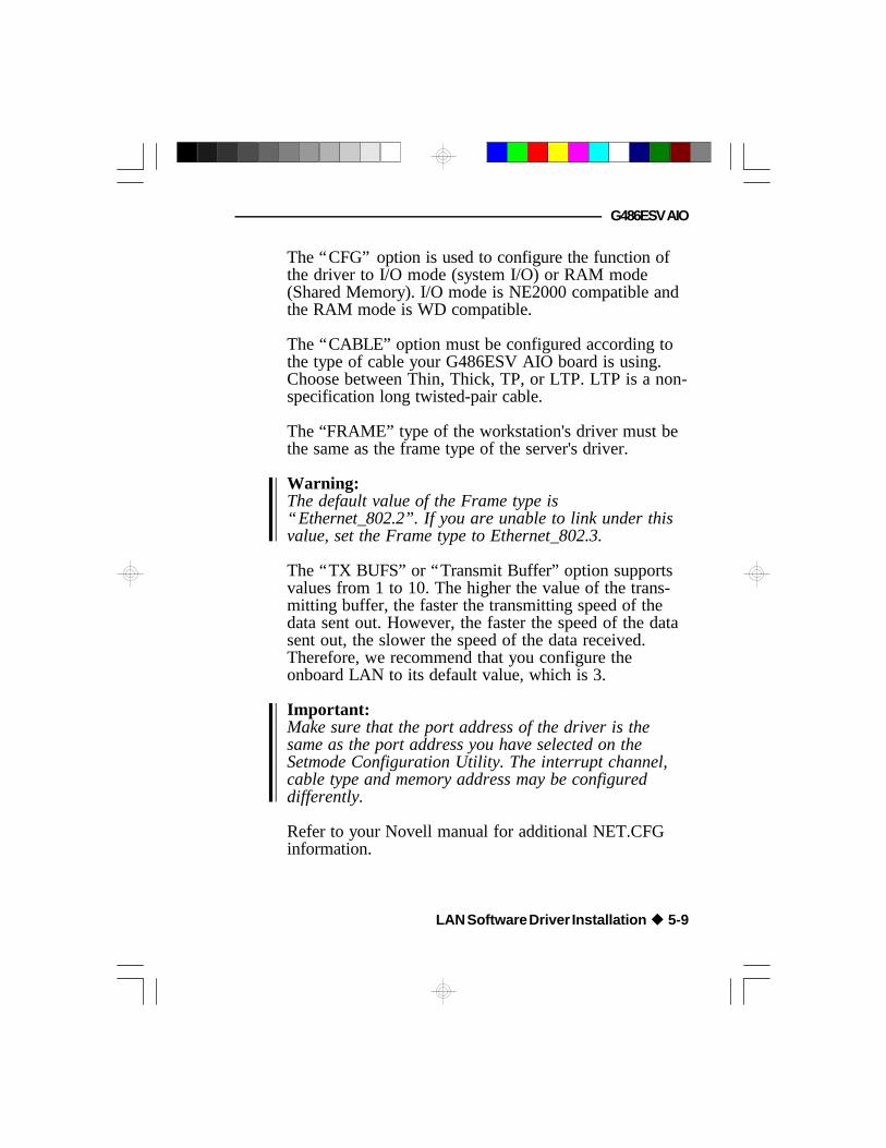
G486ESV AIO
The “CFG” option is used to configure the function ofthe driver to I/O mode (system I/O) or RAM mode(Shared Memory). I/O mode is NE2000 compatible andthe RAM mode is WD compatible.
The “CABLE” option must be configured according tothe type of cable your G486ESV AIO board is using.Choose between Thin, Thick, TP, or LTP. LTP is a non-specification long twisted-pair cable.
The “FRAME” type of the workstation's driver must bethe same as the frame type of the server's driver.
Warning:The default value of the Frame type is“Ethernet_802.2”. If you are unable to link under thisvalue, set the Frame type to Ethernet_802.3.
The “TX BUFS” or “Transmit Buffer” option supportsvalues from 1 to 10. The higher the value of the trans-mitting buffer, the faster the transmitting speed of thedata sent out. However, the faster the speed of the datasent out, the slower the speed of the data received.Therefore, we recommend that you configure theonboard LAN to its default value, which is 3.
Important:Make sure that the port address of the driver is thesame as the port address you have selected on theSetmode Configuration Utility. The interrupt channel,cable type and memory address may be configureddifferently.
Refer to your Novell manual for additional NET.CFGinformation.
LAN Software Driver Installation u 5-9

Green All-In One System Board
Installing the ODI Server Driver
Use the LOAD and BIND command to load theNetware 3.x Open Datalink Interface (ODI) serverdriver. For more information on these commands, referto Novell's manual on loading the Netware 3.x LANdriver. The device driver for the ODI server isNET700.LAN.
You may install the driver either by using the servercommand line prompted by “:” or by editing theAUTOEXEC.NCF. If you use the server command line,you need to install the driver each time you boot thesystem. If you edit the AUTOEXEC.NCF, it will auto-matically load the driver each time you boot your sys-tem.
1. Install NetWare 3.x into your system.
2. Copy the ODI server driver, NET700.LAN, fromthe “NET-700EC/ET/ECT Drivers and Utilities”diskette 1, into the hard disk drive directory wherethe Netware 3.x system files are located.
3. Run NetWare 3.x by executing the SERVER.EXEfile. Refer to Novell's manual on loading diskdrivers and mounting volumes.
5-10 u LAN Software Driver Installation

G486ESV AIO
4. To install the driver manually and change thedefault settings, type the following command at thefile server console to access the installation utility:
:LOAD INSTALL <Enter>
The “Netware 386 Installation” screen will appear.Choose the “System Options” option and press<Enter>.
The “Available System Options” screen will appear.Choose the “Edit AUTOEXEC.NCF File” optionand press <Enter>.
The “File Server AUTOEXEC.NCF File” screenwill appear. Add the following command lines ifyou are configuring the board to its I/O mode:
LOAD C:NET700 CFG=I/O PORT=300 INT=3 CABLE=THINTX BUFS=3 FRAME=ETHERNET_802.3
BIND IPX to NET700 [CFG=I/O PORT=300 INT=3FRAME=ETHERNET 802.3] net=xxx
Add the following command lines if you areconfiguring the board to its Shared Memory mode:
LOAD C:NET700 PORT=280 INT=a CFG=RAM MEM=D0000CABLE=THIN TX BUFS=5 FRAME=ETHERNET_802.3
BIND IPX to NET700 [PORT=280 MEM=D0000 INT=aFRAME=ETHERNET 802.3] net=xxx
If the values of the interrupt line, memory addressand I/O port address were not included in thecommand line, you will be prompted to includethese values. The driver will use the default valueof the other options that were not changed.
LAN Software Driver Installation u 5-11

Green All-In One System Board
Warning:The frame type of the NET700.LAN driver(server) has a different default value from thatof the NET700.COM driver (for the workstation).Make sure their frame types are the same,otherwise, your workstation and server will notwork properly.
5. After you have configured the onboard LAN, pressthe <Esc> key; the “Save AUTOEXEC.NCF File?”screen will appear. Select “Yes” to save the newconfiguration.
Important:Do not modify the configuration under the“Create the AUTOEXEC.NCF File” option. Ifyou have accidentally selected this option, press<Esc> and the “Save AUTOEXEC.NCF File?”screen will appear. Select “No” to quit withoutsaving the changes. If you choose “Yes”, it willoverwrite the previous configuration which maycause problems with your G486ESV AIO board.
6. Reboot your system. The system will reboot usingthe new configuration.
5-12 u LAN Software Driver Installation

G486ESV AIO
Microsoft LAN Manager and Windows forWorkgroups
In order to use Microsoft LAN Manager, you must firstinstall Microsoft LAN Manager 2.1 and Windows forWorkgroups into your system. Your computer can beused as a LAN Manager server, workstation, enhancedworkstation for MS-DOS, or a basic workstation forMS-DOS. Please refer to Microsoft's LAN Manager/Windows for Workgroups Installation Guide for thesystem hardware and software requirements as well asthe installation procedure of the LAN Manager/Windowsfor Workgroups software.
Installing the Microsoft LAN Manager Drivers
The drivers contained in the MSLANMAN.DOS andMSLANMAN.OS2 directories must be installed in themenu of LAN Manager 2.1 or later. Use the LANManager SETUP program to install these drivers. Referto the section “Importing Additional Network Driversand Utilities” in the Microsoft LAN Manager InstallationGuide for more information.
The SETUP utility of Microsoft LAN Manager willinstall the drivers contained in the MSLANMAN.DOSand MSLANMAN.OS2 directories. SETUP requires thatthe two information files, NIF and PROTOCOL.INI, beincluded in order to install the drivers.
The NIF file provides the information the SETUP utilitywill need to coordinate and install the various availabledrivers. Information contained in these two files includesthe driver name, the path on the diskette where thedriver is stored, and the type of driver.
LAN Software Driver Installation u 5-13

Green All-In One System Board
The PROTOCOL.INI file is used by the LANMANProtocol manager and netbind program at startup time.This file contains the NDIS and Transport specificparameters for the network. Both the NDIS (drivers)and Transport (NETBEUI) will have their ownPROTOCOL.INI. When SETUP installs NDIS andTransport, the two PROTOCOL.INI files will be mergedinto one file.
The “NET-700EC/ET/ECT Drivers and Utilities” dis-kette 1 is created with the base directory structure asshown in Appendix H. The Microsoft Setup Utility willalways look into the NIF directory for the NDIS driversnetwork information files. Additional directories that arecreated to store the drivers should be consistent with theinstall directory structure. Shown below are the conven-tions that are used with Setup.
1. Install the Microsoft LAN Manager DOS or OS/2workstation installation disk into your system.
2. Follow the instructions given by Microsoft to installthe workstation drivers.
3. If the drivers are in the menu, choose this option.Otherwise, select the “IMPORT” option to importthe drivers from the “NET-700EC/ET/ECT Driversand Utilities” diskette 1.
4. Complete the installation process according to theinstructions given by Microsoft.
As an example, the CONFIG.SYS, AUTOEXEC.BATand PROTOCOL.INI files will appear similar to theones shown on the next page:
5-14 u LAN Software Driver Installation
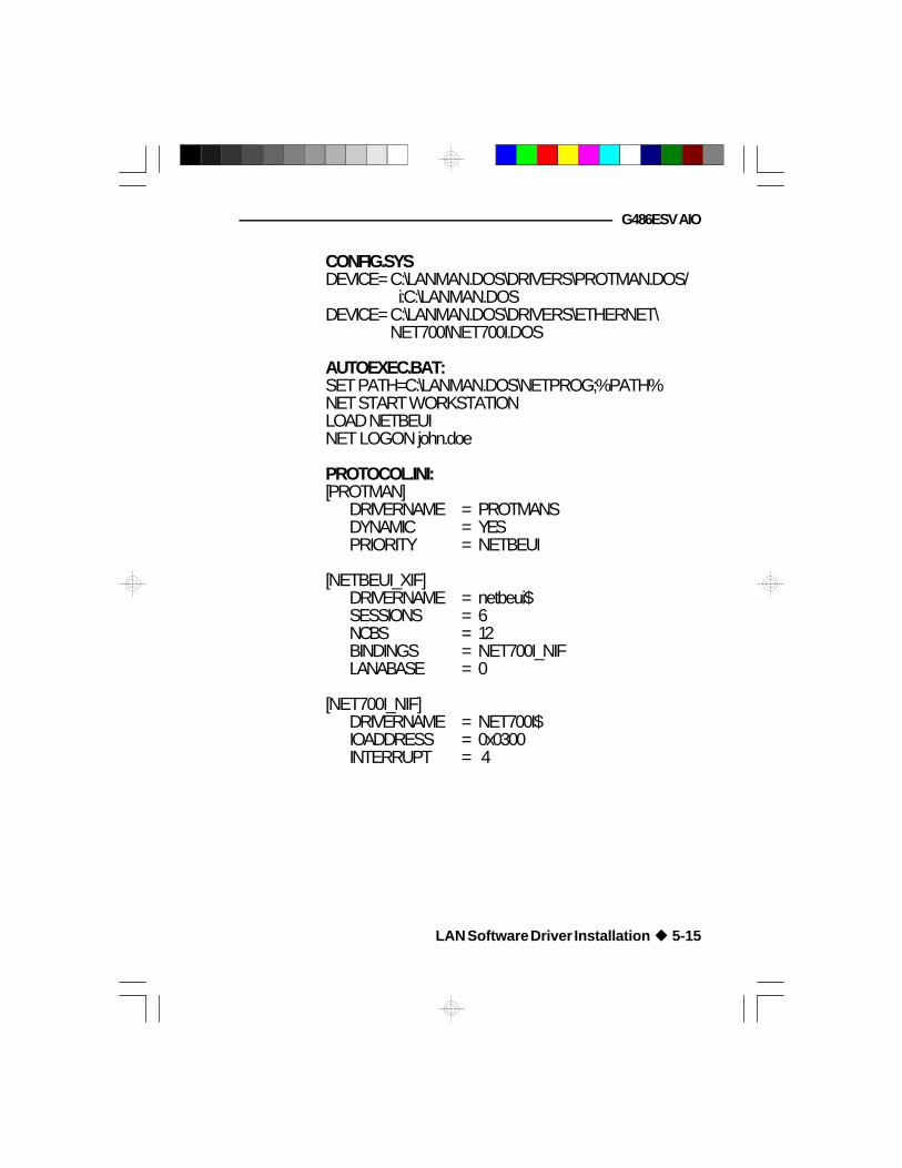
G486ESV AIO
CONFIG.SYSDEVICE=C:\LANMAN.DOS\DRIVERS\PROTMAN.DOS/
i:C:\LANMAN.DOSDEVICE=C:\LANMAN.DOS\DRIVERS\ETHERNET\
NET700I\NET700I.DOS
AUTOEXEC.BAT:SET PATH=C:\LANMAN.DOS\NETPROG;%PATH%NET START WORKSTATIONLOAD NETBEUINET LOGON john.doe
PROTOCOL.INI:[PROTMAN]
DRIVERNAME = PROTMANSDYNAMIC = YESPRIORITY = NETBEUI
[NETBEUI_XIF]DRIVERNAME = netbeui$SESSIONS = 6NCBS = 12BINDINGS = NET700I_NIFLANABASE = 0
[NET700I_NIF]DRIVERNAME = NET700I$IOADDRESS = 0x0300INTERRUPT = 4
LAN Software Driver Installation u 5-15

Green All-In One System Board
Installing the Windows for Workgroups Drivers
To install:
1. Choose the “Control Panel” icon under the ProgramManager's Main Group.
2. From the “Control Panel” screen, choose the“Network” icon.
3. The “Network Settings” dialog box will appear.Choose the “Adapters” option.
4. The “Network Adapters” dialog box will appear.Choose “Add”.
5. Under the list of network adapters, select the“Unlisted or Updated Network Adapter” option.
6. Insert the “NET-700EC/ET/ECT Drivers andUtilities” diskette 1 into drive A (or drive B) andtype the drive and directory where the driver islocated as shown below.
A:\MSLANMAN.DOS\DRIVERS\ETHERNET\NET700
Choose OK.
You can also use the “Browse” option to locate andselect the drive and directory where the driver islocated. Choose OK to exit the “Browse” dialogbox.
5-16 u LAN Software Driver Installation

G486ESV AIO
Packet Driver
The “NET-700EC/ET/ECT Drivers and Utilities” dis-kette 1 includes a Packet driver for your G486ESV AIOboard.
The PKT directory on diskette 1 contains twosubdirectories: SYSIO and SYSMEM. TheNet700I.COM driver under the SYSIO subdirectory isNE-2000+ compatible and the Net700M.COM driverunder the SYSMEM subdirectory is WD 8013 compat-ible.
Important:The device driver you use must correspond to thearchitecture of the onboard LAN, either I/O mode (NE-2000 compatible) or Shared Memory mode (WD com-patible).
Install the device driver that is under the SYSIOsubdirectory if the architecture of your onboard LAN isconfigured to I/O mode. Install the device driver that isunder the SYSMEM subdirectory if your onboard LANis configured to Shared Memory mode. Refer to thesection “Setmode Configuration Utility” for moreinformation.
Installing the Packet Driver
Insert the “NET-700EC/ET/ECT Drivers and Utilities”diskette 1 into drive A: (or B:) and type the appropriatecommand line.
The command line format of the Packet driver is:
NET700I <PACKET INT NO> <IRQ> <I/O BASE>
LAN Software Driver Installation u 5-17

Green All-In One System Board
(when the board is configured to I/O mode)NET700M <PACKET INT NO> <IRQ> <I/O BASE><MEM ADDR>(when the board is configured to Shared Memory
mode)
Listed below are the available options and their corre-sponding addresses:
<PACKET INT NO> Set Software Interrupt Number0x60 - 0x80
<IRQ> Set Hardware Interrupt Number0x3, 0x4, 0x5, 0x9, 0xa, 0xb,0xc, 0xf
<I/O BASE> Set I/O Base Address0x300, 0x320, 0x340, 0x360,0x240, 0x280, 0x2C0
<MEM ADDR> Set Memory Segment Address0xd000, 0xd400, 0xd800, 0xdc00,
0xc000, 0xc400,0xc800, 0xcc00
Shown below is an example of how the commandline should appear:
C:>A:\SYSMEM\NET700M.COM 0x60 0x3 0x300 0xD000
SCO UNIX Streams Driver
Before installing the G486ESV AIO's SCO UNIXStreams Driver, the Base System (N1-N5, M1, P1-P4),Extended System (ed, vi, link kit), TCP/IP and NFS(P11-P15) modules of the SCO Open Desk Top v3.2 orthe Basic System, Extended System, and SCO TCP/IPRuntime System of the SCO System v/386 release 3.2or later must first be installed in your system.
5-18 u LAN Software Driver Installation

G486ESV AIO
Installation Procedure
Installing the SCO UNIX Streams Driver
1. Login to the SCO UNIX operating system.
2. Type “custom” and press <Enter> to run theCustom utility. The Custom utility is provided bySCO for software installation.
3. Select the “Install” option and press <Enter>. The“Install” screen will appear.
4. Select “A New Product” option from the “Install”screen and press <Enter>. You will find this optionon the lower right side of the screen.
5. Select the “Entire Product” option and press<Enter>.
6. Insert the “NET-700EC/ET/ECT Drivers andUtilities” diskette 2 into the floppy drive. Select“Continue” to proceed with the installation processor “Quit” to stop the installation.
Making Special File and System Files
1. Type “1” to configure the onboard LAN to I/Omode or “2” to configure it to Shared Memory
mode, and press <Enter>.
2. Your board is now configured to the mode youhave selected. The message below will appear:
LAN Software Driver Installation u 5-19

Green All-In One System Board
Add, remove or modify the en700 or q to quit (a/r/m/q):
Type “A” and press <Enter> to add the “en700”driver and setup the board's hardware interface.
3. The message below will appear:
Please choose one of the following IRQ, I/O Baseand RAM Base or enter q to quit
IRQ: (3 4 5 9 10 11 12 15) [5]:
The default value is “[5]”. Type the desired valueand press <Enter>.
The option shown below will appear:
I/O base: (240 320 340 300) [240]:
The default value is “[240]”. Type the desiredvalue and press <Enter>. The next option willappear:
RAM base: (d000 d4000 d8000 dc000) [d4000]:
This message will only appear if you have chosen“2” to configure your board to Shared memorymode, in Step 1.
The default value is “[d4000]”. Type the desiredvalue and press <Enter>.
Note:i) IRQ3 and IRQ4 are for the device “sio”. You
may remove one of them, but not both.ii) IRQ11 and IRQ15 are for devices “ad” and
5-20 u LAN Software Driver Installation

G486ESV AIO
“wd1” respectively. Removing either of themwill cause a kernel linking error.
iii) Do not select I/O address “300”. Youronboard LAN will not work properly underthis address. Refer to your Open DesktopInstallation Guide for more information.
To use the default values of the IRQ, I/O baseaddress and RAM base address, you may just press
<Enter> without typing any values.
If you wish to modify the configuration, exit the“Custom” utility and type the “mkdev en70”command.
4. After you have finished installing the driver, themessage below will appear:
Relink the kernel now? (y/n/q)
The kernel must be relinked and the operatingsystem rebuilt to install the driver into the
kernel.Type “Y” and press <Enter>.
Linking with TCP/IP
1. The new configuration has been added to thesystem. The message below will appear:
Do you want this kernel to boot by default? (y/n)
Type “Y” and press <Enter>.
2. The next message will appear:
LAN Software Driver Installation u 5-21

Green All-In One System Board
Do you want the kernel environment rebuilt? (y/n)
Type “Y” and press <Enter>.3. Once the kernel has been successfully linked and
installed, the message below will appear:
Relink the TCP now? (y/n/q)
Type “Y” and press <Enter>.
4. The message below will appear:
Please choose one of the drivers listed above orenter q to quit:
Type “en70” and press <Enter>.
“en70” is the driver that will allow your onboardLAN to interact with TCP/IP.
Refer to the Open Desktop Installation Guide foradditional steps to complete the TCP/IP driverinstallation.
Rebooting the System
Reboot your system by typing the command “init 6”,then press <Enter>.
Note:1. The “en700” driver can only support the
G486ESV AIO's onboard LAN.2. The “netstat -I en70” command is not supported by
the “en700” driver.
5-22 u LAN Software Driver Installation

G486ESV AIO
v VGA Software Driver Installation
The G486ESV AIO package includes four VGAsoftware driver diskettes. These are:
• Trio 32/64 Drives for Windows NT 3.5• Trio 32/64 Drivers for OS/2 2.0 and 2.1
(Disk 1 of 2)• Trio 32/64 Drivers for OS/2 2.0 and 2.1
(Disk 2 of 2)• Trio 32/64 Utilities, DOS and Windows 3.1 Drivers
The diskettes contain “Read Me” files which provideinformation on driver installation.
VGA Software Driver Installation u 6-1

Green All-In One System Board
v Troubleshooting Checklist
If you experience difficulty with the G486ESV AIOsystem board, please refer to the checklist below. If youstill cannot isolate the problem, please contact yourdealer.
1) Check the jumper settings to ensure that the jumpersare properly set. If in doubt, refer to the “BoardConfiguration” section.
2) Verify that all HSIM modules are seated securelyinto the bank sockets.
3) Make sure the HSIM modules are in the correctlocations.
4) Check that all populated memory banks are filledwith valid size HSIMMs.
5) If your board fails to function, place the board on aflat surface and seat all socketed components
(gently press each component into itssocket).
6) Recheck the CMOS settings.
7) If you have no display, but the computer otherwiseappears to be working:
a. Recheck your monitor's power cable and On-Offswitch.
b. Make sure your brightness and contrast controlsare turned up.
7-1 u Troubleshooting Checklist

G486ESV AIO
c. If your monitor has a “TTL-Analog” switch,make sure that it is set to Analog.
8) If your screen image is distorted or goes blank whensoftware is run, the software may not be config-
ured properly to use the video. Rein-stall or change the configuration of the soft-ware to use EGA or VGA.
Extended Mode Problems
Your G486ESV AIO board is designed to be compatiblewith all standard VGA display modes and monitors. Inaddition, it offers several extended modes, with higher-than-standard resolution, to those monitors capable ofdisplaying them.
In general, VGA-compatible monitors fall into twocategories: standard “fixed-frequency” VGA monitorsand multi-frequency (multi-scanning) monitors. Multi-frequency monitors are more expensive than standardVGA monitors, and support higher resolutions thancalled for in the original VGA standard.
Note:Standard VGA monitors work with a fixed set offrequencies based only on the original VGA standard.Multi-frequency monitors work with additional scanningfrequencies.
Most standard “fixed-frequency” VGA monitors willdisplay Hi-Rez VGA board's 132-column modes.However, the 800 x 600 and 1024 x 768 extendedgraphics modes use a higher horizontal scanningfrequency than “fixed-frequency” VGA monitors arecapable of displaying. To use these modes, you musthave a multi-frequency monitor. Troubleshooting Checklist u 7-2
Green All-In One System Board
If you are having problems displaying some modes, butnot others, check the range of synchronization signalswith which your monitor is supposed to work. If thisinformation is not in the monitor's documentation,contact the monitor manufacturer or service representa-tive.
Note:On most monitors that accept either analog or TTLinputs, the text-color switch (if present) will not functionin the analog (VGA) mode.
Picture Size and Position
If you have a monitor capable of displaying theG486ESV AIO board's extended modes, you may findthat you will need to adjust the horizontal and verticalsize and position controls when you switch betweenstandard and extended modes. This is normal formulti-frequency monitors.
Interlacing
In the interlaced 1024x768 mode, the odd-numbered andeven-numbered sets of lines composing an image arealternately drawn on the screen. The sets of lines, called“fields”, alternate about 87 times a second (87Hz). Acomplete “frame” consists of two fields (odd and even),so it is completely refreshed at half the field rate, i.e.,43.5 times per second (43.5Hz). This is normal andresults from the lower persistence phosphors used inthese monitors.
7-3 u Troubleshooting Checklist

G486ESV AIO
v Appendix A: Types of ModulesThe G486ESV AIO system board allows you to popu-late memory with 256Kx36, 512Kx36, 1Mx36, 2Mx36,4Mx36 and 8Mx36 HSIM modules. The followingmodules have been tested with this board. Most unt-ested brands will work but a few may fail to do so.
For HSIM 256Kx36 Modules
Brand Chip Number
Hitachi HM514280-JP8OKI M516256B-80J
Fujitsu 81C4256-80
For HSIM 512Kx36 Modules
Brand Chip Number
Panasonic MN41C256SJ-08OKI M514256B-80JHitachi HM514280-JP8NEC 44256-70
For HSIM 1Mx36 Modules
Brand Chip Number
Toshiba TC514400ASJL-70Fujitsu 814400-80OKI M514400A-70SJNEC 4218160-60
Appendix A u A-1

Green All-In One System Board
For HSIM 2Mx36 Modules
Brand Chip Number
Micron 4C4001JDJ-6NEC 4218160-60OKI M511000B-70J
For HSIM 4Mx36 Modules
Brand Chip Number
NEC 4217400-80Mitsubishi M5M417400BJFujitsu 8117400-70PJOKI M514100B-70SJ
For HSIM 8Mx36 Modules
Brand Chip Number
OKI M511000BNEC GT-4MFujitsu 81C1000A-80
A-2 u Appendix A

G486ESV AIO
v Appendix B: System Error Report
Description
OEM specific-cache control.
Processor status (1FLAGS) verification.Test the following processor status flagscarry, zero, sign, overflow.The BIOS will set each of these flags,verify they are set, then turn each flagoff and verify it is off.
Read/Write/Verify all CPU registersexcept SS,SP and BP with data patternFF and 00.
Disable NMI, PIE, AIE, UEI, SQWV.Disable video, parity checking, DMA.Reset math coprocessor.Clear all page registers, CMOSshutdown byte.Initialize timer 0, 1 and 2, including setEISA timer to a known state.Initialize DMA controllers 0 and 1.Initialize interrupt controllers 0 and 1.Initialize EISA extended registers.
RAM must be periodically refreshed inorder to keep the memory from decaying.This function assures that the memoryrefresh function is working properly.
Keyboard controller initialization.
Verifies CMOS is working correctly,detects bad battery.
POST (hex)
C0
1
2
3
4
5
6
7
Name
Turn off chipsetcache
Processor test 1
Processor test 2
Initialize chips
Test memory refreshtoggle
Blank video, initializekeyboard
Reserved
Test CMOS interfaceand battery status
Appendix B u B-1

Green All-In One System Board
POST (hex)
BE
C1
C5
C6
8
9
A
B
C
D
E
Name
Chipset defaultinitialization
Memory presencetest
Early shadow
Cache presencetest
Setup low memory
Early cacheinitialization
Setup interruptvector table
Test CMOS RAMchecksum
Initialize keyboard
Initialize videointerface
Test videomemory
Description
Program chipset registers with power onBIOS defaults.
OEM Specific-Test to size on-boardmemory.
OEM Specific-Early Shadow enable forfast boot.
External cache size detection.
Early chip set initialization.Memory presence test.OEM chip set routines.Clear low 64K of memory.Test first 64K memory.
Cyrix CPU initialization.Cache initialization.
Initialize first 120 interrupt vectors withSPURIOUS_INT_HDLR and initializeINT 00h-1Fh according to INT_TBL.
Test CMOS RAM checksum, if bad, orinsert key pressed, load defaults.
Detect type of keyboard controller(optional).Set NUM_LOCK status.
Detect CPU clock.Read CMOS location 14h to find out typeof video in use.Detect and initialize video adapter.
Test video memory, write sign-onmessage to screen.Setup shadow RAM - Enable shadowaccording to Setup.
B-2 u Appendix B

G486ESV AIO
POST (hex)
F
10
11
12-13
14
15
16
17
18
19
1A
1B-1E
1F
Name
Test DMAcontroller 0
Test DMAcontroller 1
Test DMA pageregisters
Reserved
Test timer counter 2
Test 8259-1 maskbits
Test 8259-2 maskbits
Test stuck 8259'sinterrupt bits
Test 8259 interruptfunctionality
Test stuck NMIbits (Parity/IO check)
Reserved
Set EISA mode
Description
BIOS checksum test.Keyboard detect and initialization.
Test DMA page registers.
Test 8254 timer 0 counter 2.
Verify 8259 channel 1 masked interrupts byalternately turning off and on the interruptlines.
Verify 8259 channel 2 masked interrupts byalternately turning off and on the interruptlines.
Turn off interrupts then verify no interruptmask register is on.
Force an interrupt and verify the interruptoccurred.
Verify NMI can be cleared.
Display CPU clock.
If EISA non-volatile memory checksum isgood, execute EISA initialization. If not,execute ISA tests and clear EISA mode flag.Test EISA Configuration Memory Integrity(checksum & communication interface).
Appendix B u B-3

Green All-In One System Board
POST (hex)
20
21-2F
30
31
32
33-3B
3C
3D
3E
3F
BF
40
41
Name
Enable slot 0
Enable slots 1 - 15
Size base andextended memory
Test base andextended memory
Test EISA extendedmemory
Reserved
Setup enabled
Initialize and installmouse
Setup cachecontroller
Reserved
Chipset initialization
Initialize floppy driveand controller
Description
Initialize slot 0 (system board).
Initialize slots 1 through 15.
Size base memory from 256K to 640K andextended memory above 1MB.
Test base memory from 256K to 640K andextended memory above 1MB using variouspatterns.Note: This will be skipped in EISA mode andcan be "skipped" with ESC key in ISA mode.
If EISA mode flag is set then test EISAmemory found in slots initialization.Note: This will be skipped in ISA mode andcan be "skipped" with Esc key in EISA mode.
Detect if mouse is present, initialize mouse,install interrupt vectors.
Initialize cache controller.
Program chipset registers with Setup values.
Display virus protest disable or enable.
Initialize floppy disk drive controller and anydrives.
B-4 u Appendix B

G486ESV AIO
POST (hex)
42
43
44
45
46
47
48-4D
4E
4F
50
51
52
53
60
61
Name
Initialize hard driveand controller
Detect and initializeserial/parallel ports
Reserved
Detect and initializemath coprocessor
Reserved
Reserved
Reserved
ManufacturingPOST Loop orDisplay Messages
Security check
Write CMOS
Pre-boot enable
Initialize optionROMs
Initialize time value
Setup virus protect
Set boot speed
Description
Initialize hard drive controller and any drives.
Initialize any serial and parallel ports (alsogame port).
Initialize math coprocessor.
Reboot if manufacturing POST loop pin isset. Otherwise display any messages(i. e. any non-fatal errors that were detectedduring POST) and enter Setup.
Ask password security (optional).
Write all CMOS values back to RAM andclear screen.
Enable parity checker.Enable NMI, enable cache before boot.
Initialize any option ROMs present fromC8000h to EFFFFh.Note: When FSCAN option is enabled, willinitialize from C8000h to F7FFFh.
Initialize time value in 40h: BIOS area.
Setup virus protect according to Setup.
Set system speed for boot.
Appendix B u B-5

Green All-In One System Board
POST (hex)
62
63
B0
B1
E1-EF
FF
Name
Setup NumLock
Boot attempt
Spurious
Unclaimed NMI
Setup pages
Boot
Description
Setup NumLock status according to Setup.
Set low stack.Boot via INT 19h.
If interrupt occurs in protected mode.
If unmasked NMI occurs, displayPress F1 to disable NMI, F2 reboot.
E1-Page 1, E2-Page 2, etc.
B-6 u Appendix B
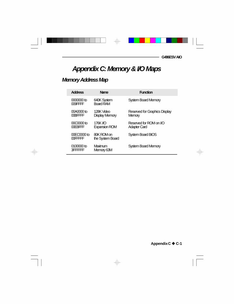
G486ESV AIO
v Appendix C: Memory & I/O MapsMemory Address Map
Address Name Function
0000000 to 640K System System Board Memory009FFFF Board RAM
00A0000 to 128K Video Reserved for Graphics Display00BFFFF Display Memory Memory
00C0000 to 176K I/O Reserved for ROM on I/O00EBFFF Expansion ROM Adapter Card
00EC0000 to 80K ROM on System Board BIOS00FFFFF the System Board
0100000 to Maximum System Board Memory3FFFFFF Memory 63M
Appendix C u C-1

Green All-In One System Board
I/O Address Map
I/O Address Function
000-01F DMA Controller 1, 8237A-5020-03F Interrupt Controller 1, 8259A, Master040-05F Timer, 8254-2060-06F 8742 (Keyboard Controller)070-07F Real-time Clock, NMI
(Non-maskable Interrupt) Mask080-09F DMA Page Memory, 74LS6120A0-08F Interrupt Controller 2, 8259A0C0-0DF DMA Controller 2, 8237A-50E8 Shadow RAM and Cache Control Bit0F0 Clear Numeric Processor
Extension Busy0F1 Reset Numeric Processor Extension0F8-OFF Numeric Processor Extension1F0-1F8 Fixed Disk200-207 Game I/O278-27F Parallel Printer Port 22F8-2FF Serial Port 2300-31F Prototype Card360-36F Reserved378-37F Parallel Printer Port 1380-38F SDLC, Bisynchronous 23A0-3AF Bisynchronous 13B0-3BF Monochrome Display and Printer Adapter3C0-3CF Reserved3D0-3DF Color/Graphics Monitor Adapter3F0-3F7 Diskette Controller3F8-3FF Serial Port 1
Note:The I/O address hex 000 to 0FF are reserved for thesystem board I/0. Hex 100 to 3FF are available on theI/O channels.
C-2 u Appendix C

G486ESV AIO
v Appendix D: 16-Bit Slot Pin Assign-ments
- 01 -- 02 -- 03 -- 04 -- 05 -- 06 -- 07 -- 08 -- 09 -- 10 -- 11 -- 12 -- 13 -- 14 -- 15 -- 16 -- 17 -- 18 -- 19 -- 20 -- 21 -- 22 -- 23 -- 24 -- 25 -- 26 -- 27 -- 28 -- 29 -- 30 -- 31 -- 32 -- 33 -- 34 -- 35 -- 36 -- 37 -- 38 -- 39 -- 40 -- 41 -- 42 -- 43 -- 44 -- 45 -- 46 -- 47 -- 48 -- 49 -- 50 -- 51 -- 52 -- 53- 54 -- 55 -- 56 -- 57 -- 58 -- 59 -- 60 -
B+12V+5VGndGnd
Reset Drv+5V DC
IRQ9-5V DCDRQ2
-12V DCOWS
+12V DCGnd
-SEMEMW-SEMEMR
-IOW-IOR
-Dack3-DRQ3-Dack1DRQ1
-RefreshCLK
IRQ7IRQ6IRQ5IRQ4IRQ3
-Dack2T/C
Bale+5V DC
OSCGndGnd+5V+5V
-Mem CS16-I/O CS16
IRQ10IRQ11IRQ12IRQ15IRQ14-Dack0DRQ0
-Dack5DRQ5
-Dack6DRQ6
-Dack7DRQ7
+5V DC-Master
GndGndGnd+5V+5V+5V
SBHELA23LA22LA21LA20LA19LA18LA17-Memr-MemwSD08SD09SD10SD11SD12SD13SD14SD15GndGndGnd+5V+5V
Solder Side A+12VGndGnd-I/O ChckSD7SD6SD5SD4SD3SD2SD1SD0-I/O ChrdyAENSA19SA18SA17SA16SA15SA14SA13SA12SA11SA10SA9SA8SA7SA6SA5SA4SA3SA2SA1SA0GndGnd+5V
Component Side
Appendix D u D-1

Green All-In One System Board
v Appendix E: VL-Bus Slot Pin AssignmentsComponent Side Solder Side
- 01 -- 02 -- 03 -- 04 -- 05 -- 06 -- 07 -- 08 -- 09 -- 10 -- 11 -- 12 -- 13 -- 14 -- 15 -- 16 -- 17 -- 18 -- 19 -- 20 -- 21 -- 22 -- 23 -- 24 -- 25 -- 26 -- 27 -- 28 -- 29 -- 30 -- 31 -- 32 -- 33 -- 34 -- 35 -- 36 -- 37 -- 38 -- 39 -- 40 -- 41 -- 42 -- 43 -- 44 -- 45 -
- 48 -- 49 -- 50 -- 51 -- 52 -- 53 -- 54 -- 55 -- 56 -- 57 -- 58 -
ADAT01DAT03GNDDAT05DAT07DAT09DAT11DAT13DAT15GNDDAT17VccDAT19DAT21DAT23DAT25GNDDAT27DAT29DAT31ADR30ADR28ADR26GNDADR24ADR22VccADR20ADR18ADR16ADR14ADR12ADR10ADR08GNDADR06ADR04WBACK#BE0#VccBE1#BE2#GNDBE3#ADS#
LRDY#LDEV<x>#LREQ<x>#GNDLGNT<x>#VccID2ID3ID4LKEN#LEADS#
BDAT00DAT02DAT04DAT06DAT08
GNDDAT10DAT12
VccDAT14DAT16DAT18DAT20
GNDDAT22DAT24DAT26DAT28DAT30
VccADR31
GNDADR29ADR27ADR25ADR23ADR21ADR19
GNDADR17ADR15
VccADR13ADR11ADR09ADR07ADR05
GNDADR03ADR02
n/cRESET#
D/C#M/IO#W/R#
RDYRTN#GNDIRQ9
BRDY#BLAST#
ID0ID1
GNDLCLK
VccLBS16#
Note:Side "A" of the connector is the add-in boardcomponent side.Side "B" of the connector is the add-in board solderside.
E-1 u Appendix E

G486ESV AIO
Pin Name No. LBC1 LBC2 LBM3 LBT
ADR<31..2> 30 O I O IADS# 1 O I O IBE<3..0> 4 O I O IBLAST# 1 O I O IBRDY# 1 I O I OD/C# 1 O I O IDAT<31..0> 32 I/O I/O I/O I/OID<4..0> 5 O O I IIRQ9 1 I I O OLBS16# 1 I O I OLCLK 1 O O I ILDEV<x>#4 1 I N/A N/A OLEADS# 1 O I O ILGNT<x>#4 1 O O I N/ALKEN# 1 O O I ILRDY# 1 I I N/A OLREQ<x>#4 1 I I O OM/IO# 1 O I O IRDYRTN# 1 O O I IRESET# 1 O O I IW/R# 1 O I O IWBACK# 1 O O I N/A(power) 8(ground) 14(reserved) 1
Total per slot 112
1 Direction of signals for the LBC if the host CPU or a system I/O busmaster is active.
2 Direction of signals for the LBC if an LBM is active.3 Direction of signals for any LBM while it owns the VL-Bus.4 One unique signal per slot or device.
Note:LBC = VL Local Bus ControllerLBM = VL Local Bus MasterLBT = VL Local Bus Target
Appendix E u E-2

Green All-In One System Board
v Appendix F: Connector Pin Assignments
CN1
ISA
Slot
VE
SA
Slot
SM1
SM2
SM3
SM4
ZIF Socket
EC802GL EC100G
Trio64/32
U53
U54
KB1J6CN3CN4CN5CN6
DP83905
CN2J5 CN2
J3
J2J4 PL1
J13
J9
JP66JP81J11 JP86
Locations of Connectors on the G486ESV AIOSystem Board
J8J10
F-1 u Appendix F

G486ESV AIO
Connector J2IDE Hard Disk Drive Connector
Pin
123456789
1011121314151617181920212223242526272829
Function
-ResetGroundD7D8D6D9D5D10D4D11D3D12D2D13D1D14D0D15GroundReservedReservedGround-IOWGround-IORGroundReservedBALEReserved
Appendix F u F-2
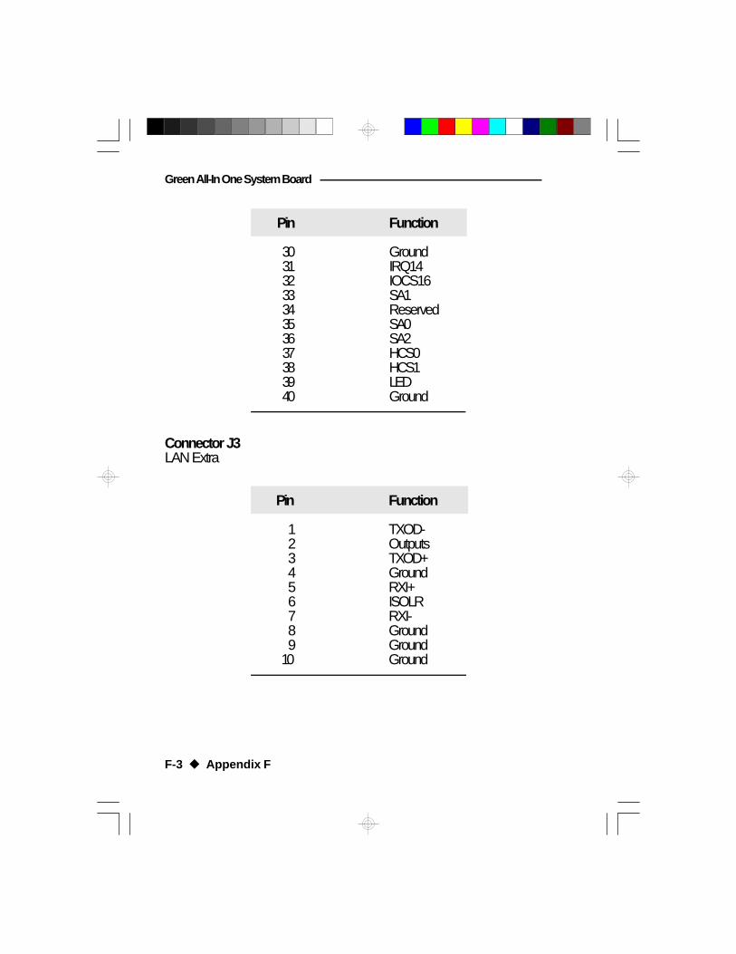
Green All-In One System Board
Pin
3031323334353637383940
Function
GroundIRQ14IOCS16SA1ReservedSA0SA2HCS0HCS1LEDGround
Connector J3LAN Extra
Pin
123456789
10
Function
TXOD-OutputsTXOD+GroundRXI+ISOLRRXI-GroundGroundGround
F-3 u Appendix F

G486ESV AIO
Connector J4Floppy Disk Drive Connector
Pin
123456789
10111213141516171819202122232425
Function
GroundDENSELGroundReservedGroundDrate0GroundIndexGroundMTR0GroundDR1GroundDR0GroundMTR1Drate1DirGroundStepGroundWrite DataGroundWrite GateGround
Appendix F u F-4

Green All-In One System Board
Connector J5AUI Connector
Pin
262728293031323334
Function
Track 0MSENWr ProtectGroundRead DataGroundHead SelectGroundDisk Change
Pin
123456789
10111213141516
Function
GroundCD+TX+GroundRX+Ground+5VGroundCD-TX-GroundRX-+12VGround+5VReserved
F-5 u Appendix F

G486ESV AIO
Connector J6PS/2 Mouse Connector
Pin
123456
Function
Mouse DataReservedGround+5VMouse ClockReserved
Connector J8Speaker Connector
Pin
1234
Function
SignalConnector to BuzzerGround+5V
Appendix F u F-6

Green All-In One System Board
The fan, installed on top of the CPU, automaticallystops once your system enters the Green mode.
Connector J9Fan Connector
Pin Function
1 +12V2 Ground
Connector J10Power LED/Keylock Connector
Pin Function
1 LED Signal2 Reserved3 Ground4 Keylock Signal5 Ground
Connector J11Reset Switch Connector
Pin Function
1 Reset2 Ground
F-7 u Appendix F

G486ESV AIO
Connector J13Feature Connector
1920212223242526
GroundBlankGroundH SyncNot UsedV SyncNot UsedGround
Pin
123456789
101112131415161718
Function
GroundPD0GroundPD1GroundPD2EnVideoPD3EnSyncPD4EnPclkPD5Not UsedPD6GroundPD7GroundPclk
Appendix F u F-8

Green All-In One System Board
Connector JP66IDE LED
Pin
12
Function
VccSignal
Connector JP81Standby Mode LED
Pin
12
Function
GroundSignal
Connector JP86Standby Mode Switch Connector
Pin
12
Function
GroundSignal
F-9 u Appendix F

G486ESV AIO
Connector KB1PS/2 Keyboard Connector
Pin
123456
Function
Keyboard DataReservedGround+5VKeyboard ClockReserved
Pin
123456789
101112
Connector PL1Power Connector
Function
Power Good+5V+12V-12VGroundGroundGroundGround-5V+5V+5V+5V
Appendix F u F-10

Green All-In One System Board
Connector CN1BNC Connector
Pin
12
Function
ISOLROutputs
Connector CN2RJ-45 Connector
Pin
12345678
Function
TXOD-TXOD+RXI+ReservedReservedRIX-ReservedReserved
F-11 u Appendix F

G486ESV AIO
Connectors CN3 and CN4Primary and Secondary Serial Ports
Pin
123456789
Function
DCD (Data Carrier Detect)RX (Receive Data)TX (Transmit Data)DTR (Data Terminal Ready)Ground (Signal Ground)DSR (Data Set Ready)RTS (Request to Send)CTS (Clear to Send)RI (Ring Indicator)
Connector CN5Parallel Printer Port
Pin
123456789
1011
Function
-StrobeData 0Data 1Data 2Data 3Data 4Data 5Data 6Data 7-AckBusy
Appendix F u F-12

Green All-In One System Board
Pin
1213141516171819202122232425
Function
Paper EmptySelect-Autofd-Error-Init-SlctinGroundGroundGroundGroundGroundGroundGroundGround
F-13 u Appendix F

G486ESV AIO
Connector CN6Analog Connector
Pin
123456789
101112131415
Function
RedGreenBlueNot UsedGroundRed Return (ground)Green Return (ground)Blue Return (ground)Key (no pin)Sync Return (ground)Not UsedDDC1 - DataHorizontal SyncVertical SyncDDC1 - CLK
Appendix F u F-14

Green All-In One System Board
v Appendix G: Award BIOS Hard Disk Table
Type
1
2
3456
789
10111213
141516
1718192021222324252627
28
Size(MB)
Cylinders Heads Sectors
17
17
17171717
17171717171717
17
17
1717171717171717171717
17
TEAC SD510,MMI 112, 5412Seagate ST225,ST4026
Seagate ST125,Tandon TM262
Tandon TM 703
Disctron 526,MMI M125
Microscience HH725,Syquest 3250, 3425
Seagate ST4038
Seagate ST4051Seagate ST4096Maxtor 2085Maxtor 2140,Priam S14Maxtor 2190,Priam S19
10
20
30624620
3030
11220354920
42
20
40565930423010407671
111
152
306
615
615940940615
462733900820855855306
733
612
977977
1024733733306977
1024122412241224
1024
4
4
6864
85
153578
7
4
5775754597
11
15
ExampleModel
WritePrecomp
128
300
300512512
None
256NoneNoneNoneNoneNone
128
None
0
300None
512300300300
0NoneNoneNoneNone
None
LandZone
305
615
615940940615
511733901820855855319
733
663
977977
1023732732733336976
102312231223
1223
(Reserved)
G-1 u Appendix G

G486ESV AIO
Type
29
30
3132333435363738394041
42
43444546
Size(MB)
Cylinders Heads Sectors
17
17
1717171717171717171717
26
17263338
Maxtor 1085,Micropolis 1325Maxtor 1105 1120,4780Maxtor 1170CDC 9415
Maxtor 1140, 4380Seagate ST251Seagate 4053Miniscribe 3053/6053Miniscribe 3053/6053RLLMiniscribe 3650Miniscribe 3675 RLLConner CP3104Conner CP3204
68
93
836985
10211011917
1361144042
65
4061
100203
1024
918
9251024102410241024102410241024918820
1024
1024
809809776684
8
11
119
101213142
161565
5
668
16
ExampleModel
WritePrecomp
None
None
NoneNoneNoneNoneNoneNoneNoneNoneNoneNoneNone
None
NoneNoneNoneNone
LandZone
1023
1023
1023926
1023102310231023102310231023820
1023
1023
852852775685
User
Appendix G u G-2

Green All-In One System Board
v Appendix H: LAN Software Diskettes
NET-700EC/ET/ECT Drivers and Utilities (Diskette 1)
The “NET-700EC/ET/ECT Drivers and Utilities” dis-kette 1 contains drivers for Netware 2.x and 3.x, LANManager 2.1, Windows for Workgroups and Packetdriver.
NET-700EC/ET/ECT Drivers and Utilities for SCO UNIX(Diskette 2)
The “NET-700EC/ET/ECT Drivers and Utilities forSCO UNIX” diskette 2 contains drivers for SCO UNIX3.2.x. Please review the contents of the diskette for alisting of files it contains.
H-1 u Appendix H

G486ESV AIO
S3 Video Modes
v Appendix I: Reference Table
Mode(Hex)
Dot Clock(MHz)
40.000
40.000
25.175
25.175
31.500
31.500
36.00
40.000
50.000
49.500
36.000
40.000
50.000
49.500
44.900
65.000
75.000
80.000
44.900
65.000
75.000
80.000
RefreshRate(Hz)
70
70
70
60
72
75
56
60
72
75
56
60
72
75
43 (I)
60
70
75
43 (I)
60
70
75
Sweep(KHz)
Bits/Pixel
ScreenResolution
VBEDITMode
31.5
31.5
31.5
31.5
37.9
37.5
35.1
37.9
48.1
47.5
35.1
37.9
48.1
46.8
35.5
48.4
56.5
60.2
35.5
48.4
56.5
60.2
4
4
8
8
8
8
4
4
4
4
8
8
8
8
4
4
4
4
8
8
8
8
54
55
68
69
69
69
6A
6A
6A
6A
6B
6B
6B
6B
6C
6C
6C
6C
6D
6D
6D
6D
10A
109
100
101
101
101
102
102
102
102
103
103
103
103
104
104
104
104
105
105
105
105
132x43 Chars
132x25 Chars
640x400
640x480
640x480
640x480
800x600
800x600
800x600
800x600
800x600
800x600
800x600
800x600
1024x768
1024x768
1024x768
1024x768
1024x768
1024x768
1024x768
1024x768
Appendix I u I-1

Green All-In One System Board
45 (I)
45 (I)
60
72
75
60
72
75
60
72
75
60
72
75
60
72
75
60
72
75
60
72
75
Mode(Hex)
Dot Clock(MHz)
RefreshRate(Hz)
Sweep(KHz)
Bits/Pixel
ScreenResolution
VBEDITMode
6E
6F
6F
6F
6F
70
70
70
71
71
71
72
72
72
73
73
73
74
74
74
75
75
75
106
107
107
107
107
110
110
110
111
111
111
112
112
112
113
113
113
114
114
114
115
115
115
1280x1024
1280x1024
1280x1024
1280x1024
1280x1024
640x480
640x480
640x480
640x480
640x480
640x480
640x480
640x480
640x480
800x600
800x600
800x600
800x600
800x600
800x600
800x600
800x600
800x600
4
8
8
8
8
15
15
15
16
16
16
32
32
32
15
15
15
16
16
16
32
32
32
47.7
47.7
63.7
77.7
79.5
31.5
37.5
37.5
31.5
37.5
37.5
31.5
37.9
37.5
37.9
48.1
46.8
37.9
48.1
46.8
37.9
48.1
46.8
75.000
75.000
110.000
130.000
135.000
25.175
31.500
31.500
25.175
31.500
31.500
25.175
31.500
31.500
40.000
50.000
49.500
40.000
50.000
49.500
40.000
50.000
49.500
I-2 u Appendix I

G486ESV AIO
1024x768
1024x768
1024x768
1024x768
1024x768
1024x768
1024x768
1024x768
1024x768
1280x1024
1280x1024
1600x1200
640x480
640x480
640x480
800x600
800x600
800x600
800x600
800x600
800x600
800x600
800x600
Mode(Hex)
Dot Clock(MHz)
RefreshRate(Hz)
Sweep(KHz)
Bits/Pixel
ScreenResolution
VBEDITMode
116
116
116
116
117
117
117
117
118
119
11A
120
201
201
201
202
202
202
202
203
203
203
203
76
76
76
76
77
77
77
77
78
79
7A
7C
49
49
49
4A
4A
4A
4A
4B
4B
4B
4B
16
15
15
15
16
16
16
16
32
15
16
8
8
8
8
4
4
4
4
8
8
8
8
35.0
48.9
56.5
60.4
35.0
48.9
56.5
60.4
35.2
48.7
48.7
62.0
31.5
37.9
37.5
35.1
37.9
48.1
46.9
35.1
37.9
48.1
46.8
43 (I)
60
70
75
43 (I)
60
70
75
43 (I)
45 (I)
45 (I)
48.5 (I)
60
72
75
56
60
72
75
56
60
72
75
44.900
65.000
75.000
80.000
44.900
65.000
75.000
80.000
44.900
75.000
75.000
130.000
25.175
31.500
31.500
36.000
40.000
50.000
49.500
36.000
40.000
50.000
49.500
Appendix I u I-3

Green All-In One System Board
Mode(Hex)
Dot Clock(MHz)
RefreshRate(Hz)
Sweep(KHz)
Bits/Pixel
ScreenResolution
VBEDITMode
204
204
204
204
4C
4C
4C
4C
4
4
4
4
35.5
48.4
56.5
60.3
44.900
65.000
75.000
80.000
1024x768
1024x768
1024x768
1024x768
43 (I)
60
70
75
205
205
205
205
207
208
208
208
208
1024x768
1024x768
1024x768
1024x768
1152x864
1280x1024
1280x1024
1280x1024
1280x1024
8
8
8
8
8
4
4
4
4
35.5
48.4
56.5
60.2
55.3
47.7
63.7
77.7
79.8
43 (I)
60
70
75
60
43 (I)
60
72
75
44.900
65.000
75.000
80.000
80.000
75.000
110.000
130.000
135.000
4D
4D
4D
4D
4E
4F
4F
4F
4F
I-4 u Appendix I

G486ESV AIO
Ch0-Reserved for UserCh1-SDLCCh2-DisketteCh3-Reserved for User
DMA Controller 1
Appendix J: System Overview
DMA Channels
DMA Controller 2
Ch4-Cascade for CTRL 1Ch5-Reserved for UserCh6-Reserved for UserCh7-Reserved for User
Note:DMA controller 1 supports 8-bit data transfer.DMA controller 2 supports 16-bit data transfer.
Address Generation for DMA Channels 3 to 0
Source DMA Page Memory DMA Controller 1
Address A23 < >A16 A15 < > A0
Address Generation for DMA Channels 7 to 5
Source DMA Page Memory DMA Controller 2
Address A23 < >A17 A16 < > A1
Appendix J u J-1

Green All-In One System Board
Page Memory Address
I/O Port Address
0081H0082H0083H0087H0089H008AH008BH
DMA Channel 2DMA Channel 3DMA Channel 1DMA Channel 0DMA Channel 6DMA Channel 7DMA Channel 5
System Interrupts
Page Memory
NMI Parity or I/O Channel Check
Note:The non-maskable interrupt (NMI) of the G486ESV AIOis used to report memory parity errors. The memoryparity is derived from the system board memory and I/Oadapter optional memory.
Interrupt Controller 1
IRQ0-Timer Output (Out 0)IRQ1-Keyboard (Output Buffer Full)
IRQ2-Interrupt from INTR2IRQ3-Serial Port 2IRQ4-Serial Port 1IRQ5-Parallel Port 278, 378IRQ6-Diskette ControllerIRQ7-Parallel Port 378, 3BC
Interrupt Controller 2
IRQ8-Realtime Clock INTIRQ9-Software Redirected
to INT 0AH (IRQ2)IRQ10-ReservedIRQ11-ReservedIRQ12-PS/2 MouseIRQ13-CoprocessorIRQ14-Fixed Disk ControllerIRQ15-Reserved
J-2 u Appendix J

G486ESV AIO
Note:Any or all interrupts including NMI may be masked.The 16 levels of system interrupts have the followingpriority: IRQ0>IRQ1>IRQ8>IRQ9>IRQ10>IRQ11>IRQ12>IRQ13>IRQ14>IRQ15>IRQ3>IRQ4>IRQ5>IRQ6>IRQ7.
System Timers
Channel 0 System Timer (IRQ0)
Channel 1 Refresh Request Generator(15us Rate Generator Period Signal)
Tone Generation for SpeakerChannel 2
Real-Time Clock
Address
000102030405060708090A0B0C0D
Function
SecondsSecond AlarmMinutesMinute AlarmHoursHour AlarmDay of WeekDate of MonthMonthYearRegister ARegister BRegister CRegister D
Appendix J u J-3

Green All-In One System Board

G486ESV AIO


![BlueData - KC Wirefree · BlueData KC-1114 Class 1 Bluetooth Hi Power Data Module Version December 10, 2014 Page 6 Interface Pins AIO Interface Pins [1‐2] AIO 0 and AIO 1 are enabled](https://static.documents.pub/doc/80x56/603bdfac99cc8f637211fb90/bluedata-kc-bluedata-kc-1114-class-1-bluetooth-hi-power-data-module-version-december.jpg)


![FP-AIO-610 and cFP-AIO-610 Operating Instructions ... the user manual for the FieldPoint network module you are ... Input Circuitry on One Channel of the [c]FP-AIO-610 ... FP-AIO-610](https://static.documents.pub/doc/80x56/5b46f8f17f8b9a501f8c819a/fp-aio-610-and-cfp-aio-610-operating-instructions-the-user-manual-for-the-fieldpoint.jpg)
![AIO-PHOA232 | Portraiture · Web view[Type text][Type text][Type text] COURSE CODE: AIO-PHOA232 Portraiture Milestone 5. AIO-PHOA232 | Portraiture](https://static.documents.pub/doc/80x56/60211ff80165680e0b567d86/aio-phoa232-portraiture-web-view-type-texttype-texttype-text-course-code.jpg)


