1 GAIL GAS LIMITED CITY GAS DISTRIBUTION PROJECT CLIENT JOB NO. - SPECIFICATION FOR ONSHORE PIPELINE CONSTRUCTION TOTAL SHEETS 14 DOCUMENT NO 11 0290 02 07 02 016 0 16.10.09 ISSUED FOR TENDER GV AP SB B 25.08.09 ISSUED FOR CLIENT’S COMMENTS BG AP SB A 24.08.09 ISSUED FOR IDC BG AP SB REV DATE DESCRIPTION PREP CHK APPR Page 101 of 775
8.0 LINING UP .............................................................................................................................................10
1.1 This specification defines the minimum requirements for the various activities to be carried out by Contractor for the construction of onshore pipelines.
1.2 The various activities covered in this specification include all works during the following stages of
pipeline construction :
- Clearing, grubbing and grading of right-of-way ; - Staking of the pipeline route ; - Handling, hauling, stringing and stacking/storing of all materials ; - Trenching ; - Field – bending of line pipe ; - Lining-up and Welding - Pipeline laying ; - Backfilling ; - Tie-in ; - Hydrostatic testing, dewatering and drying - Installation of auxiliary facilities and appurtenances forming a part of pipeline installation; - Clean-up and restoration of right-of-way;
1.3 Contractor shall submit detailed work procedures including drawings, calculations, as required equipment and manpower deployment details for the all pipeline activities to Owner for approval. Entire work shall be carried out as per approved procedures and to the satisfaction of Owner.
2.0 DEFINITIONS
For this specification the following definitions shall apply: OWNER : GAIL (GAS) LIMITED CONSULTANT : WOOD GROUP ENGINEERING INDIA PVT. LTD.(WGI) CONTRACTOR : The company named as such in the deed. SHALL/MUST/IS TO BE : A mandatory requirement
SHOULD : A non-mandatory requirement, advisory or Recommendation
3.0 REFERENCE CODES, STANDARDS AND SPECIFICATIONS
3.1 Reference has been made in this specification to the latest codes, standards and specifications:
i.) ASME B31.8 - Gas Transmission and Distribution Piping systems
ii) ASME B31.4 - Pipeline transportation systems for liquid hydrocarbons and other liquids.
iii) API 1104 - Standard for Welding Pipelines and related facilities
iv) API 1105 - Bulletin on construction practices for oil and products pipelines
v) Part 192
Title 49
- Transportation of natural and other gas by pipeline (U.S Department of Transportation – Pipeline safety standards)
Page 103 of 775
DOCUMENT NO. REV
11-0290-02-07-02-016 0
SPECIFICATION FOR ONSHORE PIPELINE CONSTRUCTION
SHEET 4 OF 14
vi) Part 195 - Transportation of liquids by pipeline (U.S department of Transportation – Pipeline safety standards)
vii) PNGRB NOTIFICATION
Dated: 27/08/08
Schedule-1
- Technical Standards and specifications including safety standards for city or local natural gas distribution network.
viii) OISD 141 - Design construction requirements for cross-country hydrocarbon pipelines.
4.0 RIGHT-OF-WAY (ROW)
4.1 General
Contractor shall notify Owner well in advance during the progress of work, the method of construction for crossing road, pipeline and other existing installations, services and obstacles.
Where the ROW comes within the area of influence of high voltage electrical installations, the special measures shall be taken.
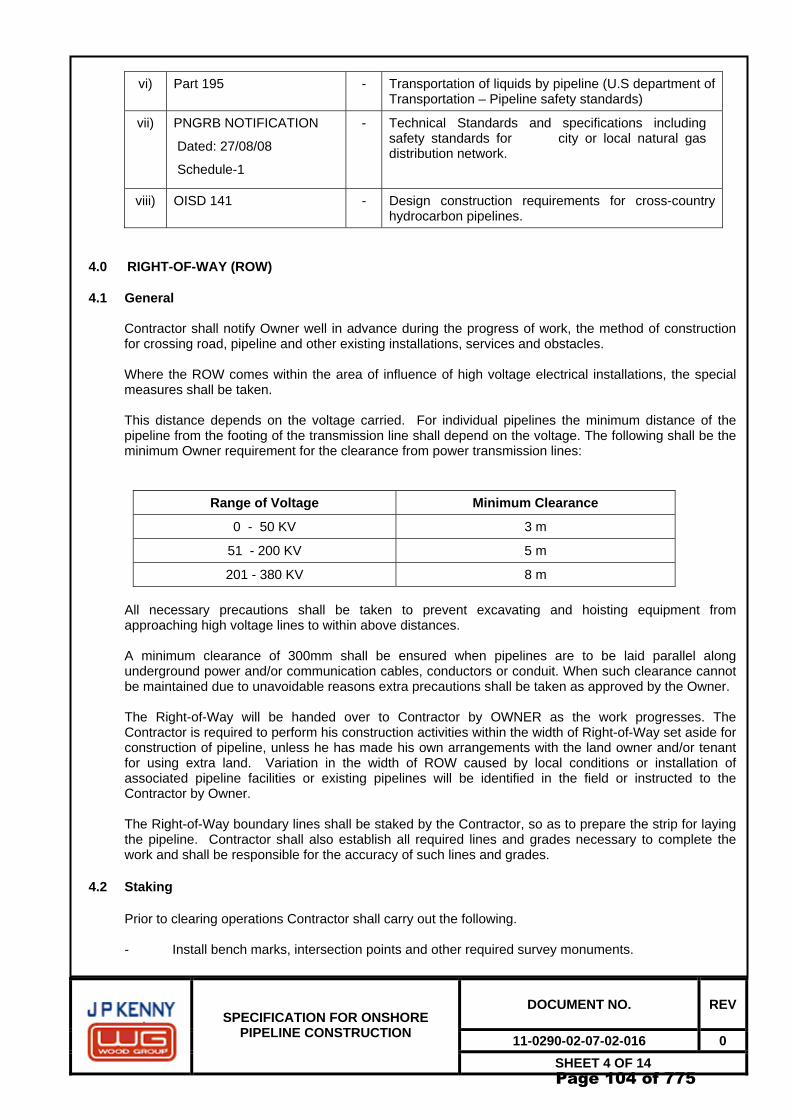
This distance depends on the voltage carried. For individual pipelines the minimum distance of the pipeline from the footing of the transmission line shall depend on the voltage. The following shall be the minimum Owner requirement for the clearance from power transmission lines:
Range of Voltage Minimum Clearance
0 - 50 KV 3 m
51 - 200 KV 5 m
201 - 380 KV 8 m All necessary precautions shall be taken to prevent excavating and hoisting equipment from approaching high voltage lines to within above distances.
A minimum clearance of 300mm shall be ensured when pipelines are to be laid parallel along underground power and/or communication cables, conductors or conduit. When such clearance cannot be maintained due to unavoidable reasons extra precautions shall be taken as approved by the Owner.
The Right-of-Way will be handed over to Contractor by OWNER as the work progresses. The Contractor is required to perform his construction activities within the width of Right-of-Way set aside for construction of pipeline, unless he has made his own arrangements with the land owner and/or tenant for using extra land. Variation in the width of ROW caused by local conditions or installation of associated pipeline facilities or existing pipelines will be identified in the field or instructed to the Contractor by Owner.
The Right-of-Way boundary lines shall be staked by the Contractor, so as to prepare the strip for laying the pipeline. Contractor shall also establish all required lines and grades necessary to complete the work and shall be responsible for the accuracy of such lines and grades.
4.2 Staking
Prior to clearing operations Contractor shall carry out the following. - Install bench marks, intersection points and other required survey monuments.
Page 104 of 775
DOCUMENT NO. REV
11-0290-02-07-02-016 0
SPECIFICATION FOR ONSHORE PIPELINE CONSTRUCTION
SHEET 5 OF 14
- Stake markers in the centerline of the pipeline at distances of maximum 100 meters for straight line sections and maximum 10 meters for horizontal bends. Stake two ROW markers at boundaries at least at every 100 metres.
- Install distinct markers locating and indicating special points, such as but not limited to:
Contract limits, obstacle crossings, change of wall thickness, including corresponding chainage etc.
- All markers shall be of suitable materials so as to last till replacement with permanent markers and shall be colored distinctly for easy identification. Type, material and coloring of stake markers shall be subjected to approval of Owner. Any deviation from the approved alignment shall be executed by Contractor after seeking Owner’s approval in writing prior to clearing operations.
- Contractor shall be responsible for the maintenance and replacement of the reference line markers until the permanent pipeline markers are placed.
4.3 Fencing
If Owner demands, contractor shall install temporary fencing on either side of ROW wherever it is required to ensure safety and non-interference with others. For convenience of construction, Contractor shall install temporary gates to the fencing as per Owner’s guidelines.
4.4 Clearing and Grading
4.4.1 Clearing of Obstacles
Any obstacle, which may hinder the construction and laying of the pipeline along the approved pipeline route and for a strip of land of the size provided shall be removed.
4.4.2 Clearing of Vegetation
All grubbed stumps, timber bush, undergrowth and roots shall be cut and removed from the ROW and shall be disposed off in a method satisfactory to Owner and authorities having jurisdictions. ROW cross fall shall not exceed 10%.
4.4.3 Uprooting of Trees
All trees which may hinder the construction of the pipeline along the approved pipeline route that belong to the protected green belt, reserved forest and other areas demarcated by the government authorities and any other tree in the opinion of the Owner requiring relocation / re-plantation shall be relocated and replanted by the Contractor at an alternate location as recommended by the jurisdiction authorities / Owner. All such uprooting and re-plantation of trees shall be carried out by the Contractor in a manner that is satisfactory to the jurisdiction authorities / Owner.
Contractor shall submit a procedure for uprooting and replanting of trees to the Owner for approval.
Trees that are required to be uprooted and not specified / recommended for re-plantation by the jurisdiction authorities / Owner shall be disposed of as debris and cleared from the ROW / Project site by the Contractor.
4.4.4 Grading of ROW
Contractor shall grade the pipeline Right-of-way as required for proper installation of the pipeline, for providing access to the pipeline during construction, and for ensuring that the pipeline is constructed in accordance with the most up-to-date engineering and construction practices. During entire period of
Page 105 of 775
DOCUMENT NO. REV
11-0290-02-07-02-016 0
SPECIFICATION FOR ONSHORE PIPELINE CONSTRUCTION
SHEET 6 OF 14
pipeline construction and testing, Contractor shall maintain the ROW in motorable condition. Final cleared & graded ROW shall be subjected to approval of Owner.
4.5 Approach roads
Grading operations should normally be carried out along the Right-of-way with mechanical excavators or manually. In certain areas, grading may have to be resorted exclusively by blasting.
In plain, rough or steep terrain, Contractor may have to grade access roads and temporary bypass roads for its own use. Where such access roads do not fall on the Right-of-way, Contractor shall obtain necessary written permission from land owners and tenants and be responsible for all damages caused by the construction and use of such roads at no extra cost to Owner. Where rocky terrain is encountered, grading shall be carried out in all types of solid rocks which cannot be removed until loosened by blasting, drilling or by other recognised methods of quarrying solid rocks.
4.6 Provision of detours
Contractor shall be responsible for moving his equipment and men across or around watercourses and road crossings. This may require the construction of temporary bridges or culverts. Contractor shall ensure that such temporary works shall not interfere with normal water flow, avoid overflows, traffic, keep the existing morphology unchanged and shall not unduly damage the banks of water courses. No public ditches or drains shall be filled or bridged for passage of equipment until Contractor has secured written approval of the authorities having jurisdiction over the same. Contractor shall furnish OWNER a copy of all such approval.
4.7 Off right-of-way damages
Any damage to property outside ROW shall be restored or settled to the Contractor’s account.
5.0 HANDLING, HAULING, STRINGING AND STORING OF MATERIALS
5.1 General
Contractor shall be fully responsible for all materials and their identification until the time such that the pipes and other materials are installed in permanent installation.
Contractor shall be fully responsible for arranging and paying for stacking/storage areas for the pipeline materials. However, method of stacking/storage shall be approved by Owner.
5.2 Line pipes
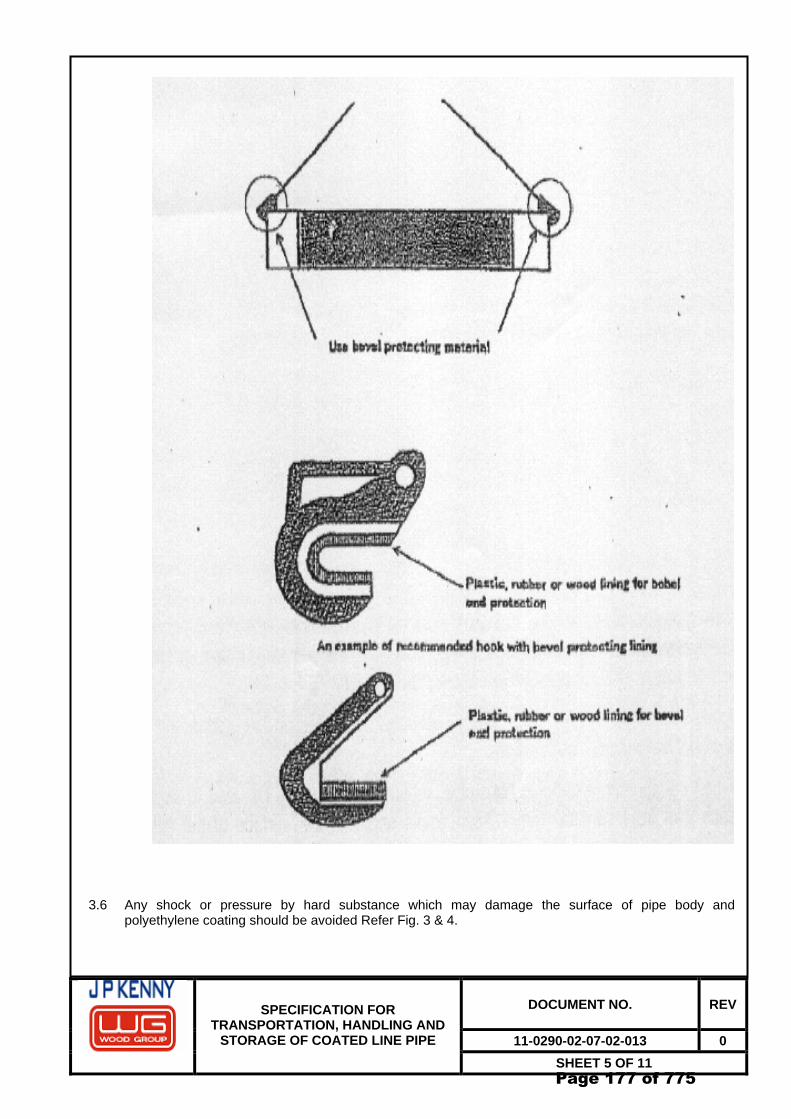
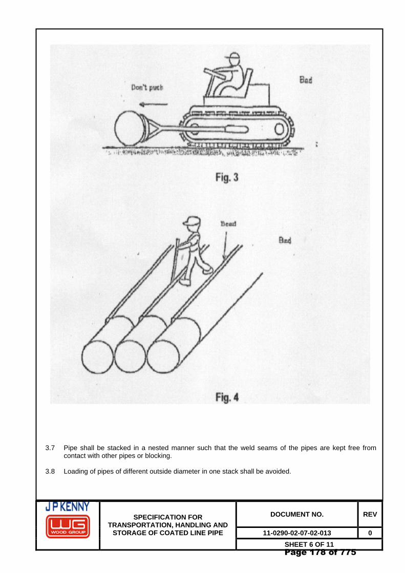
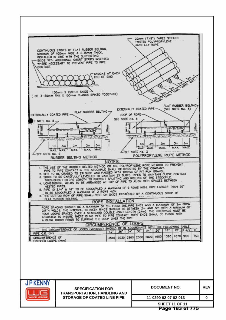
The Contractor shall load, unload, transport and stockpile the bare/coated pipes using approved suitable means and in a manner to avoid damage to the pipe and coating. Contractor shall submit to Owner a complete procedure indicating the manner and arrangement used for handling, transportation and stacking of bare/coated pipes for Owner’s approval prior to commencement of handling operations.
Stacks shall consist of limited number of layers so that the pressure exercised by the pipes own weight does not cause damage to the coating. Contractor shall submit the staking height calculations as per API RP 5L1 to Owner for approval. Stacks of different diameters, wall thickness and damaged rejected pipe shall be separately segregated and identified properly. The pipes shall be stacked at a slope so that driving rain does not collect inside the pipe.
The ends of pipes during handling and stacking shall be protected with bevel protectors. Supports shall be provided for at least 10% of the pipeline length. These supports shall be lined with rubber protection. The second layer and subsequent layers shall be separated from each other by material such as straw in plastic covers or mineral wool strips or equivalent.
Materials excluding line pipes shall be stored in sheltered storages.
Page 106 of 775
DOCUMENT NO. REV
11-0290-02-07-02-016 0
SPECIFICATION FOR ONSHORE PIPELINE CONSTRUCTION
SHEET 7 OF 14
5.3 Stringing of pipe
Pipes shall be unloaded from the stringing trucks/trailors and lowered to the ground by means of boom tractor or swinging crane or other suitable equipment using lifting devices. Dragging or sliding of pipe shall not be permitted. Special precaution shall be taken during stringing of corrosion coated pipe as per the special requirements of previous paragraph. Stringing of pipe shall only be carried out in daylight and after clearing and grading operations have been completed. Pipe shall not be strung on the Right-of-way in rocky areas where blasting may be required, until all blasting is complete and the area is cleared of all debris. Contractor shall submit to Owner for approval a complete procedure for stringing of line pipes.
5.4 Repair of damaged pipes
After the pipe has been strung on the Right-of-way it shall be inspected by the Contractor and the Owner and all defective pipes and pipe ends shall be repaired. Defective pipe shall be repaired or rejected as the Owner may direct as per the requirements of specification.
5.5 Identification
For all pipes, the number and length shall be identified and recorded properly. Before a pipe end is cut, the painted pipe number and cold die stamped pipe number shall be transferred by Contractor in presence of Owner to either side of the joint which is to be made by cutting.
6.0 TRENCHING
6.1 Contractor shall excavate and maintain the pipeline trench on the staked center line of the pipeline taking into account the curves of the pipeline.
6.2 Excavation
6.2.1 Contractor shall, by any method approved by Owner, dig the pipeline trench on the cleared and graded
Right-of-way.
6.2.2 In cultivated land the arable soil shall be properly prescribed and same to be replaced at original place during backfilling as advised by Owner.
Care shall be exercised to see that fresh soil recovered from trenching operation, intended to be used for backfilling over the laid pipe in the trench, is not mixed with loose debris or foreign material. The excavated material shall never be deposited over or against the strung pipe.
6.2.3 In steep slope areas or on the hillside, before commencing the works, proper barriers or other protection
shall be provided to prevent the removed materials from rolling downhill.
6.2.4 In certain slopy sections, before the trench cuts through the water table, proper drainage shall be ensured both near the ditch and the right-of-way in order to guarantee soil stability.
6.3 Blasting
6.3.1 Contractor shall execute the blasting as per approved procedures, which will also detail out safety
precautions to safe guard the existing pipelines.
6.3.2 No blasting is allowed within 15m of any existing pipeline or structures (either above or below ground).
Where blasting is to be carried out, between 50m and 15m away from any existing pipelines or structures (either below or above ground), the Contractor shall submit a procedure for controlled blasting e.g. break-holes, slit trench etc. Contractor shall perform a trial blast for Owner’s approval.
Page 107 of 775
DOCUMENT NO. REV
11-0290-02-07-02-016 0
SPECIFICATION FOR ONSHORE PIPELINE CONSTRUCTION
SHEET 8 OF 14
6.4 Normal cover and trench dimensions The trench shall be excavated to a minimum width maintaining clearance on both sides of the installed pipeline and to a depth to maintain the cover of the pipeline as indicated in the other contract documents or approved procedure.
Pipeline shall be laid with at least 500mm free clearance from the obstacles or as specified in the drawings or wherever it is required by concerned authorities. The following minimum cover shall be maintained:
Location Minimum cover a) Normal Excavation 1m b) Drains, Ditches lined & Unlined
Note: 1. The above-mentioned minimum cover requirements shall be valid for all class locations. 2. Minimum depth of cover shall be measured from the top of pipe coating/ casing pipe to the top
of undisturbed surface of the soil, or top of graded working strip whichever is lower. 3. Cover shall be measured from the top of road or top of rail, as the case may be. 4. In case of rivers, which are prone to scour and erosion, adequate safe cover (min.2.5m) shall
be provided below the predicted scour profile during the lifetime of pipeline. Contractor shall establish the scour level based on data provided by authorities.
At points where the contour of the earth may require extra depth to fit the minimum radius of the bend as specified or to eliminate unnecessary bending of pipe or where deeper trench is required at the approaches to crossings of roadways, streams etc. contractor shall excavate such additional depths as may be necessary at no extra cost to Owner.
6.5 Negative buoyancy to the pipe
Contractor shall dewater if necessary, using well point system or other suitable systems, and then install the pipe in the trench and backfill the trench. All underground utilities shall be located and protected as per the guidelines of jurisdiction authority/Owner. Contractor shall check if up-floating danger for the pipeline is present in open trench. If such danger of up-floating is present, Contractor shall take appropriate measures to prevent up-floating such as applying soil dams and dewatering of trench or temporary filling of water into the line (in exceptional cases) as approved by Owner. Contractor shall furnish details of all negative buoyancy calculations to the Owner for approval. Contractor shall carry out any anti buoyancy measures only after obtaining Owner’s approval for such calculations. In case of presence of water on the ditch bottom when the pipeline is being laid, the ditch shall be drained to the extent and for the time required to make a visual inspection of the ditch bottom. After such inspection, the presence of water will be allowed provided its level does not cause sliding of the ditch sides and pipe floating before backfilling. Wherever up-floating of the pipeline after backfilling is indicated, anti-buoyancy measures shall be provided by Contractor for areas indicated in the drawings or as may be encountered during construction using the following method: - Applying a continuous concrete coating around the pipe
Page 108 of 775
DOCUMENT NO. REV
11-0290-02-07-02-016 0
SPECIFICATION FOR ONSHORE PIPELINE CONSTRUCTION
SHEET 9 OF 14
Any other anti-buoyancy method adopted by the Contractor shall require prior written approval from the Owner. The above provisions shall be in accordance with the relevant specifications and/or approved procedures / drawings and to the satisfaction of Owner.
6.6 Padding
In all cases where rock or gravel or hard soil is encountered in the bottom of the trench, extra padding shall be provided by Contractor as per Owner’s instructions. The thickness of the compacted padding shall not be less than 150mm. In those areas that are to be padded, the trench shall be at least 150mm deeper than otherwise required, and evenly and sufficiently padded to keep the pipe when in place, at least 150mm above bottom of excavated trench.
The thickness of compacted padding on top of pipe shall be at least 150mm.Exact extent of trench padding shall be as per Owner’s instructions. Padding materials that are approved by Owner shall be graded soil / sand and/or other materials containing no gravel, rock, or lumps of hard soil.
Contractor shall keep the trench in good condition until the pipe is laid.
7.0 BENDING
Contractor shall preferably provide for changes of vertical and horizontal alignment by making elastic bends. Contractor may provide cold field bends, at his option for change of direction and change of slope. Owner at his option may authorise fabricated bends for installation at points where in Owner’s judgement the use of such bends is unavoidable.
Over bends shall be made in such a manner that the centre of the bend clears the high points of the trench bottom. Sag bends shall fit the bottom of the trench and side bends shall conform and leave specified clearance to the outside wall of the trench.
7.1 Cold field bends
7.1.1 The minimum radius of cold field bends shall be as follows:
Nominal Pipe Size (NPS)
Minimum Radius of Cold Bend
Less than 12”
21D
14 “ - 18 “
30D
Greater than 20 “
40D
Spiral SAW line pipes shall not be used for fabrication of cold field bends.
Contractor shall use a bending machine and mandrel and employ recognized and accepted methods of
bending of coated pipe in accordance with good pipeline construction practice. However, bending machines shall be capable of making bends without wrinkles, buckles, stretching and with minimum damage to the coating.
7.1.2 Contractor shall, before the start of the work, submit and demonstrate to Owner a bending procedure,
which shall conform with the recommendations of the bending machine manufacturer. The procedure
Page 109 of 775
DOCUMENT NO. REV
11-0290-02-07-02-016 0
SPECIFICATION FOR ONSHORE PIPELINE CONSTRUCTION
SHEET 10 OF 14
shall include amongst other steps – lengths, maximum degree per pull and method and accuracy of measurement during pulling of the bend. This procedure and the equipment used shall be subjected to Owner’s approval.
7.1.3 For welded pipes, longitudinal seam shall be suitably placed as per approved procedure so that the
weld seam shall not be overstressed.
7.1.4 The ends of each bent length shall be straight and not involved anyway in the bending. The length of the straight section shall permit easy joining. In no event shall the end of the bend be closer than 1.0m from the end of a pipe.
7.1.5 The ovality used on each pipe by bending shall be less than 2.5% of the nominal diameter at any point.
Ovality is defined as the reduction or increase in the internal diameter of the pipe compared with the nominal internal diameter. A check shall be performed on all bends in the presence of Owner by passing a gauging pig / buckle detector consisting of two discs with a diameter equal to 95% of the nominal internal diameter of the pipe connected rigidly together at a distance equal to 300mm.
7.1.6 Cold bent pipes on site shall have the corrosion coating carefully checked with the aid of a holiday
detector for cracks in the coating down to the pipe wall. It must also be checked whether the coating has been disbanded from the pipe wall during bending by beating with a wooden mallet along the outer radius. Any defects or disbanding of the coating caused during bending shall be repaired at the Contractor’s expense in accordance with Owner’s approved procedures.
7.2 Mitre and unsatisfactory bends
All bends showing buckling, wrinkles, cracks or other visible defects or which are in any way in disagreement, in whole or in part, with this specification shall be rejected.
No mitre bends shall be permitted in the construction of the pipeline. Cutting of factory made bends and cold field bends for any purpose is not permitted.
8.0 LINING UP
Each length of pipe shall be thoroughly examined internally and externally to make sure that it is free from visual defects, damage, severe corrosion (sea water pitting), dirt, animals or any other foreign objects. Each length of the pipe shall be adequately swabbed, either by use of canvas belt disc of proper diameter or by other methods approved by the Owner. Damaged/ corroded pipes shall be kept separate. Each length of pipe shall be pulled through just before being welded. Contactor shall submit a detail procedure for Lining of line pipe to Owner for approval.
8.1 Pipe defects and repairs
8.1.1 Acceptability of defects in the pipe detected during inspection at the work site shall be determined in
accordance with approved procedures or Code ASME B31.8/B31.4 whichever is more stringent.
8.1.2 Repair on line pipe shall be executed as specified in specification or Code ASME B31.8 whichever is more stringent.
Repair of damaged pipe ends by hammering and/or heating is not allowed. Contractor shall submit
detailed procedure for pipe defects and repairs to Owner for approval
8.2 Skid spacing
8.2.1 A strip of soft material shall be placed in between skid and pipe to protect the external coating of pipe from any damage.
8.2.2 The pipes shall be maintained from skids at the minimum distance of 500mm above ground.
Page 110 of 775
DOCUMENT NO. REV
11-0290-02-07-02-016 0
SPECIFICATION FOR ONSHORE PIPELINE CONSTRUCTION
SHEET 11 OF 14
8.3 Night caps/temporary caps
After each day’s work or when work is interrupted, the open ends of the welded strings of pipes shall be capped with a securely closed metal cap as approved by Owner.
9.0 LAYING
9.1 Lowering in trench
9.1.1 Lowering shall follow as soon as possible, after the completion of the field joint coating of the pipeline. In the case of parallel pipelines, laying shall be carried out by means of successive operations, if possible without interruption. Contractor shall submit a detail procedure for lowering of pipeline to Owner for approval.
9.1.2 Before lowering in, a complete check by a full circle holiday detector for pipe coating and for field joint
coating shall be carried out and all damages repaired as agreed by Owner at Contractor’s cost. All the points on the pipeline where the coating has been in contact with either skids or with lifting equipment shall be properly checked. Where water is present in the trench, no laying shall be permitted until the ditch has been drained.
9.1.3 The pipeline shall be lifted and laid using, for all movements, necessary suitable equipment of non-
abrasive material having adequate width for the fragility of the coating. Care shall be exercised while removing the slings from around the coated pipe after it has been lowered into the trench. Any damage caused to the coating shall be promptly repaired. Lowering in utilizing standard pipe cradles shall be permitted if Contractor demonstrates that pipe coating is not damaged. No sling shall be put around field joint coating.
9.1.4 The portion of the pipeline between trench and bank shall be supported by as many side-booms as
required and approved by Owner for holding the line in gentle S-curve maintaining minimum elastic bend radius as specified in approved procedure. Lowering in and back filling shall preferably be carried out at the highest ambient temperature.
In laying parallel pipelines in the same trench, the minimum distances between the pipelines indicated in the approved drawings shall be maintained.
9.1.5 Over-head sections
a) The following works shall be completed before proceeding with the assembly and laying of overhead pipelines :
- Construction of the pipe support structures or of mounts on supports. - Paints and/or coating of the pipework, as indicated in the engineering specification.
b) The erection of the supports shall be carried out taking care that the elevation and alignment is
in accordance with the drawings.
In the case of metal work supports, pre-fabrication and/or assembly shall take into account the maximum allowed free span and the supports shall not interfere with the pipeline welds.
c) In case roller supports are used, the rollers shall be lubricated, and then checked for smooth
rotation. In case of seizure, the defect shall be repaired or roller shall be replaced. In the case of overhead section where the pipeline is slanting, the alignment of the end supports shall be made after placing the pipeline in position. Before installation of the pipe section, all the rollers shall be perfectly centered acting on the seat of the support plates.
The above alignment operations shall be carried out before connecting the overhead section with the ends of the buried section.
Page 111 of 775
DOCUMENT NO. REV
11-0290-02-07-02-016 0
SPECIFICATION FOR ONSHORE PIPELINE CONSTRUCTION
SHEET 12 OF 14
d) Lifting, moving and laying of the pipeline shall be carried out in accordance with the provisions
of this specification.
An insulation sheet shall be installed to isolate the pipe from the support or support from the earth. The sheet shall be hard polyethylene at least 5mm thick. It shall extend to at least 25 mm outside the saddles or clamps.
e) Moving supports, if any shall be centered on their support and allow for a movement of at least 300mm in both directions.
f) A comprehensive report / method statement on the laying operation to be used shall be
submitted to the Owner well in advance for approval. The report as a minimum shall include, but not limited to the following:
- Method of installation by lifting (as a preferred method). - Pulling method and related calculations, whenever lifting method cannot be used. - Pulling device and its characteristics. - Method of anchoring the pulling device - Characteristics of the pulling rope - Braking device, if any. - Pipeline assembly system.
10.0 BACK-FILLING
10.1 Backfilling shall be carried out immediately after the pipeline has been laid in the trench, inspected and approved by the Owner, so as to provide a natural anchorage for the pipeline, thus avoiding long exposure of coating to high temperature, damaging actions of adverse weather conditions, sliding down of trench sides and pipe movement in the trench. If immediate back filling is not possible, a covering of at least 200mm of earth shall be placed over and around the pipe coatings. Contractor shall submit to Owner the detailed procedure for backfilling for approval.
10.2 As directed by Client/PMC, wherever hard rocks/soil are encountered, padding and rock shield shall be
provided across the pipe to cover all exposed pipe area to avoid any possible damages during back filling of hard materials like rock, gravel, lumps of hard soil etc.
10.3 When trench has been dug through roads, all back fills shall be executed by sand or suitable material
as approved by Owner and shall be thoroughly compacted. In certain cases, special compaction methods, such as moistening or ramming of the backfill in layer may be required as advised by Owner.
10.4 In areas prone to soil erosion, back filling shall be carried out as per approved procedures, carefully and
to the satisfaction of the Owner/authorities having jurisdiction.
10.5 Contractor shall furnish materials and install breakers in the trench in step areas (slope generally 10% and more) for the purpose of preventing erosion of the backfill. The type of breakers installed shall be as per the approved drawings. Breakers shall be constructed of grout bags filled with a mixture of 4: 1 Sand: Portland cement at Owner’s direction.
11.0 PIPELINE TIE-IN
11.1 The unconnected sections of the pipeline at various locations have to be tied in after the sections are coated, lowered and backfilled. The sections to be connected shall have at the ends - sections of over lapping, uncovered pipe of sufficient length to absorb, without including excessive stresses in the steel, small displacements necessary for perfect alignment and connection of the ends.
Page 112 of 775
DOCUMENT NO. REV
11-0290-02-07-02-016 0
SPECIFICATION FOR ONSHORE PIPELINE CONSTRUCTION
SHEET 13 OF 14
11.2 If a pup end cannot be avoided for tie-in, the minimum length that shall be added is 1.0 meters and two
or more such pups shall not be welded together. All cut-off lengths greater than 1.0 meters shall be moved ahead in order to be welded into the pipeline at a suitable location. Tie-in with two or more pups may be used provided that they each have minimum length of 1.0 meter and are separated by an entire length of pipe. In no case more than three (3) welds shall be permitted on a 10 meter length of pipeline.
11.3 Maximum post hydrostatic tie-ins (Golden tie – ins) shall be limited to 10 nos. only.
12.0 CROSSINGS
Pipe line sections at all major crossings like State and National Highways, Railways, major canals and lined canal / distributaries shall be laid by boring with casing pipe complying to all other statutory requirements. All other crossings shall be executed by open cut method unless otherwise specified in the Contract or specified by statutory authorities.
13.0 INSTALLATION OF INSULATING JOINTS
13.1 Insulating joints shall be installed at the locations shown in the drawings. Contractor shall obtain approval from the Owner before installation of the insulating joints.
13.2 Handling and installation of the insulating joints shall be carried out with all precautions required to
avoid damage and excessive stresses and that the original pup length is not reduced.
13.3 The insulating joints and the welded joints shall be protected by external coating as per the relevant specifications issued for the purpose.
14.0 WORKING SPREAD LIMITATIONS
Contractor shall, in general, observe the following maximum distances between the working mainline spread. Between Row grading, clearing and backfilling : 05Kms.(To be confirmed) Between Backfilling and final clean up : 05Kms.(To be confirmed)
15.0 CLEAN-UP & RESTORATION OF RIGHT-OF-WAY
15.1 After all required tests have been concluded satisfactorily Contractor shall clean up the site as laid down in the specifications issued for the purpose. The site finish shall be graded in accordance with the approved drawings.
15.2 Contractor shall restore the Row and all sites used for the construction of pipelines, water crossings and
other structures in accordance with Owner’s instructions, and deliver them to the satisfaction of OWNER.
16.0 PIPELINE MARKERS
16.1 Contractor shall submit detailed drawings for pipeline markers to the Owner for approval. After approval, all markers shall be installed along the pipeline route as advised by Owner. As a minimum the markings shall be provided at intervals / spacing as follows:
Marker Type Minimum Spacing Requirement
Kilo Meter Post One marker every one kilometre
Page 113 of 775
DOCUMENT NO. REV
11-0290-02-07-02-016 0
SPECIFICATION FOR ONSHORE PIPELINE CONSTRUCTION
SHEET 14 OF 14
Aerial Marker One marker at every five kilometres
Navigable Water ways One each on either bank of the navigable water way
Boundary Markers One each on either side of the boundary of the ROW at intervals of 250 m.
Direction Markers One at the centre of curvature of the turning point .
One each at a distance of 200 m on either side of the alignment.
Warning Signs:
All road / railroad crossings
Water course, nala, canal
One no. on either side of the road / railroad
a) One no. for width less than 15m
b) Two nos. on either side of the crossing for width greater than 15 m and all cased crossings
Page 114 of 775
GAIL GAS LIMITED
CITY GAS DISTRIBUTION PROJECT
CLIENT JOB NO. - SPECIFICATION OF WATER CROSSING BY TRENCHING
13.0 FINAL CLEAN-UP ........................................................................................................................................9
This specification defines the minimum technical requirements for the various activities to be performed by Contractor for the construction of pipeline at major water crossings by conventional trenching method. Provisions of this specification are applicable only for "major water crossings” specifically named as such in the Contract.
1.2 Responsibility
Contractor shall be deemed to have inspected and examined the work area and its surroundings and to have satisfied himself so far as practicable as to the form and nature thereof, including sub-surface conditions, hydrological and climatic conditions, the extent and nature of the work and materials necessary for the completion of the work, and the means of access to the work area. Contractor shall be deemed to have obtained the necessary information mentioned above to risks, contingencies and all other circumstances, which may influence the work.
2.0 DEFINITION
For this specification the following definitions shall apply: OWNER : GAIL (GAS) LIMITED
CONSULTANT : WOOD GROUP ENGINEERING INDIA PVT. LTD. (WGI)
CONTRACTOR : The Company named as such in the deed.
SHALL/MUST/IS TO BE : A mandatory requirement SHOULD : A non-mandatory requirement, advisory or recommendation
3.0 REFERENCES
3.1 Codes and Standards Reference has been made in this specification to the latest edition/revision of the following codes,
standards and specification. a) ANSI B 31.8 Gas Transmissions and Distribution Piping System b) ANSI B 31.4 Liquid Petroleum Transportation Piping System c) API RP 1102 Steel Pipeline Crossing Railroads and Highways
d) Part 192 Title 49 Transportation of Natural and other Gas by Pipeline (US Department of Transportation – Pipeline Safety Standards)
e) Part 195 Transportation of Liquids by Pipeline (US Department of Transportation – Pipeline Safety Standards).
f) OISD 141 Design Construction Requirements for Cross Country Hydrocarbon Pipelines
g) PNGRB NOTIFICATION Technical Standards and specifications including safety standards for Dated: 27/08/08 city or local natural gas distribution network.
Schedule-1
Page 117 of 775
DOCUMENT NO. REV
011-290-02-07-02-018 0
SPECIFICATION OF WATER CROSSING BY TRENCHING
SHEET 4 OF 9
4.0 PROJECT GENERAL REQUIREMENTS
4.1 Before start of the construction, CONTRACTOR shall submit in triplicate to Owner/Consultant for approval for each major water crossing a complete report containing the following as minimum:
i) Installation methodology. ii) Proposed time schedule, indicating start and finish dates and detailed break-up of duration for all critical
activities associated with the work. iii) Required work area along with layout and location and other drawings / sketches iv) Equipment (including number and capacity of each equipment) and proposed manpower deployment
during construction. v) Proposed sub-contractors and/or vendors along with their scope of work.
All works of the pipeline major water crossing shall be performed in accordance with the approved
construction drawings, procedures, other applicable documents as per the Contract, good pipeline construction practices and as directed by Owner/Consultant.
The description of the installation method as a minimum shall include the followings as applicable:
a) Study of water currents in relation to the method of pulling. b) Preparation of fabrication yard and launching Areas. c) Pipeline construction details (hauling, stringing. welding, concrete coating etc.) d) Pre-test procedure. e) Procedure for anti-corrosion coating of field joints. f) Pulling method and related calculations. g) Pulling arrangement including launching and anchoring device. h) Dredging /trenching methodology. i) Method of rectification of damages to the pipeline, during launching. j) Final test procedure after back-filling. k) Method of back-filling, bank protection and survey. l) Safety systems during operations. m) Communication. n) Abandonment and recovery procedures.
Approval by Owner/Consultant for the methods used by Contractor shall in no way relieve Contractor
from the sole responsibility for safe and satisfactory installation of the pipe in crossing.
4.2 Owner’s responsibility to obtain necessary permits from the Authorities having jurisdiction, for performing the work. Contractor shall comply with all the conditions and requirements issued by authorities having jurisdiction in the area where the work is to be performed.
Contractor shall make own arrangement for temporary roads, bypasses and diversions. 4.3 Prior to start of any work, Contractor shall carry out a survey of the major water crossings and
acquaint himself with site conditions and collect any data regarding the water velocity and the tidal variations, and flow pattern and shall verify the suitability of his equipment and the method of construction.
5.0 METHODOLOGY
This brief methodology is intended to describe the best management practices ( BMPs) for mitigating environmental damage on account of natural gas pipelines crossing rivers and streams by open cut method;
Options are: (1) Open Cut Dry (“Isolated”) Crossing (2) Open Cut Wet (“In-stream”) Crossing
Page 118 of 775
DOCUMENT NO. REV
011-290-02-07-02-018 0
SPECIFICATION OF WATER CROSSING BY TRENCHING
SHEET 5 OF 9
1) Open Cut Dry (“Isolated”) Crossing:
This method is best suited for narrow streams and crossings (widths not greater than 10.0m, and flows greater than 4cu.m/sec).
Under this method, the stream is isolated and then diverted around the pipeline crossing while a trench is excavated and the pipeline installed.
This may be done in two stages, each being approximately half of the river crossing at a time.
After isolation of the first half of the crossing, a flexible casing pipe with inside diameter larger than outside diameter of the carrier pipe is installed at the required depth of cover.
The cofferdam is then dismantled, and reinstalled on the opposite side of crossing such that it encompasses the end of the just installed carrier pipe.
The second half of crossing is excavated, and the pipeline or carrier pipe is pulled through the casing pipe to the other side of crossing. The stream is then stabilized, and allowed to return to its bed.
2) Open Cut Wet Crossing
Under this method, the stream is not diverted during construction.
The pipe is installed and backfilled while the stream continues flowing through the site. To minimize environmental damage, it is necessary to complete construction in the shortest possible time;
6.0 TRENCHING
6.1 Dredging/Excavation
6.1.1 Contractor shall dredge or excavate the trench for the crossing in conformity with the approved drawings. The trench shall be excavated to such depth as required to provide the minimum cover and the pipeline configuration as specified. The pipeline profile of the crossing shall be followed as accurately as possible. Before laying, the trench shall be cleaned and levelled. The trench shall be subject to verification by Owner/Consultant prior to installation of the pipeline.
6.1.2 Contractor is fully responsible for the execution of the blasting, whenever permitted, the dredging and excavation work, hopping of the soil, transportation, dumping on Owner /Consultant.
6.1.3 Navigation traffic through the waterway shall not be obstructed, unless permission has been given
thereto. Contractor shall issue all necessary publications according to the local regulations. Instructions given by Authorities shall be followed accurately and immediately, so that no hindrance occurs to the traffic through the waterway.
Contractor cannot request a compensation if his work is hampered or delayed due to weather conditions, any obstacles or by any traffic on the spot, where work is executed.
6.1.4 During the execution of dredging work, the Contractor shall take bearing measurements and levels on
behalf of Owner/consultant. Contractor shall render assistance for this purpose and make available for Owner/consultant appropriate equipment's, survey boats, and manpower before the excavation work of the water-crossing trench can be started. Contractor, if so desired by Owner/consultant, shall make cross-profiles at intervals of not more than 10.0m of the bottom of the watercourse along the surveyed
centre line of the water crossing. Vertical measurements shall be taken with a sonic recording device and shall be taken with such accuracy that each depth is known within 0.2m. Vertical measurements shall be taken at points
Page 119 of 775
DOCUMENT NO. REV
011-290-02-07-02-018 0
SPECIFICATION OF WATER CROSSING BY TRENCHING
SHEET 6 OF 9
averaging not more than 5.0m apart and no two measurements shall be more than 7.0m apart. The cross profiles shall extend at least 10m on both sides of the top of the trench.
All measurements shall be witnessed by Owner/Consultant. The resulting profile, corrected to the elevation of the undisturbed water-course, shall be plotted on a 1:200 vertical and horizontal scale.
6.1.5 Immediately before installation of the water crossing to the excavated trench,
Contractor shall prepare a profile of the trench bottom along the surveyed centre line of the water crossing for comparison with the reference profile. Contractor shall also make cross sections of the trench at intervals of not more than 25m. All profile and cross section measurements shall be taken as specified and shall be witnessed by Owner/Consultant.
The above data shall be submitted to Owner/Consultant for approval and Owner/Consultant will approve or reject the trench excavation as completed within 24 hours after receipt of the profile and cross section.
6.1.6 Contractor shall keep the trench in good condition until the pipe is pulled into position. Contractor shall
do whatever is required to excavate and maintain the trench, install the pipe in it and backfill the trench in accordance with the Owner/Consultant specifications at no extra cost to Owner/Consultant.
6.1.7 Contractor shall grade the trench in such a manner so as to give the maximum amount of uniform
support to the pipeline when it is pulled into place. The maximum unsupported span shall not exceed 8m.
6.2 Method of Discharge
In case the Contractor uses pumping lines to discharge the soil, he shall obtain all necessary permits for carrying out such activities.
Pumping lines, discharges and siphons shall be installed by Contractor and removed before the completion of the work. All crossings with existing roads, the pumping lines shall be led through a casing pipe bored/jacked under the road or led through a porch over the road. A stress calculation must then be handed over to Owner/Consultant.
All the necessary provisions to embank the dumping area and also the soil basins shall be made by Contractor. Contractor shall be responsible for transportation of the soil and dumping on land and is liable for damage to works of third parties caused by leakage of pumping lines etc. Contractor shall at all time prevent overflow of pumping water, soil or sand embankments, or roads.
Contractor shall also safeguard Owner/consultant from claims of compensation by third parties due to encountered damage.
6.3 Dikes, Dams and Weirs
Contractor shall install temporary provisions in the existing dikes, dams, etc. to prevent flooding of low areas.
As a general requirement in existing dikes, dams etc., a double substituting weir must be installed before start of excavation in the existing dike or dam. Such a double substituting weir can be a closed wall of sheet piling, supported by soil. The provisions shall be such that the underwater profile of the dredged trench, the water movement caused by ships, etc. causes no slides/cave-ins of the dike or dam.
7.0 CONTINUOUS CONCRETE COATING
Contractor shall provide concrete coating over the pipeline including the bends in accordance with the specification issued for the purpose and approved procedure. Contractor shall coat the weld joints in
Page 120 of 775
DOCUMENT NO. REV
011-290-02-07-02-018 0
SPECIFICATION OF WATER CROSSING BY TRENCHING
SHEET 7 OF 9
order to arrive at a continuously concrete coated pipeline. However such concrete coating on the weld joints shall be applied after the pre-hydrostatic testing.
8.0 HYDROSTATIC TESTING
Contractor shall carry out pre and post hydrostatic testing of the pipeline section at the crossing. After post hydro-static test the pipeline section shall be integrated with the main line for the final hydrostatic testing along mainline. The testing of the pipeline section shall be in accordance with document No. 11-0290-01-07-02-020 Hydrostatic Testing Specification.
9.0 INSTALLATION
9.1 Contractor shall submit a detailed methodology, which is to be adopted for installing the pipeline to owner/consultant for approval. Contractor shall calculate all stresses in the pipeline while laying and check whether the stresses remain within permissible limits. A set of all calculations shall be submitted to the Owner/consultant for approval.
9.2 The equipment for pipe pulling shall be in good condition and the pipeline shall be laid without impact or
jerking and is not subjected to stresses of any type other than those, which are allowable. Minimum allowed radius of curvature shall be followed particularly at the end of the launching way towards the water in the freely suspended section.
9.3 After the water-crossing section has been installed in place, Contractor shall fill this section including
the pertaining land sections with water for testing.
9.4 Contractor shall check if the position and cover over the pipeline at the water crossing are in accordance with the approval drawing, by means of a profile of the pipeline, before and after the water-crossing section is filled with water. Contractor shall lower each pipeline section, which is not sufficiently deep either by dredging or by jetting the underlying ground.
9.5 The maximum allowed horizontal deviation from the required centre-line shall be limited by the
following:
Pipe Size Max. Deviation from center line Diameter < 16” 300 mm Diameter > 16” 500 mm
9.6 Contractor shall ensure that prior to backfill, the pipeline when laid in the trench shall conform to
the bottom contour of the trench, so that it will be firmly, uniformly and continuously supported. Contractor shall facilitate the work of the diver and shall furnish the necessary equipment and helpers (other than actual diving equipment) necessary for the diver/inspector to perform inspection work at the bottom of the trench by Owner/Consultant
9.7 If the pipe does not properly fit inside the trench or does not rest at sufficient depth to satisfy the minimum requirements of cover as specified in approved drawings, the Contractor shall make necessary corrections either to the trench or to the pipe alignment or to both so that the pipe, when finally in position inside the trench, shall fully meet the specifications and relay the pipeline to the specification, failing which Contractor may be asked to remove the pipeline and delay the pipeline to meet the specification. This shall be done at no extra cost to the Owner/Consultant.
9.8 Installation of parallel pipelines (if applicable)
When Parallel pipelines are required to be installed for major water crossing. Contractor shall comply with the following requirements.
9.8.1 Depending on the diameters of the parallel pipelines, the characteristics of the crossing and the
limitations of Contractor's equipment, Contractor may propose installation of the parallel pipelines either together in a combined operation or separately in a common trench.
Page 121 of 775
DOCUMENT NO. REV
011-290-02-07-02-018 0
SPECIFICATION OF WATER CROSSING BY TRENCHING
SHEET 8 OF 9
9.8.2 If the pipelines are installed together, the minimum clear distance between the parallel pipelines
(measures from the outside diameters of the concrete coated pipes) shall be 300mm. Contractor shall provide spacers at sufficient intervals along the length of the pipe section(s), securely fixed to the pipes, or shall propose other suitable alternative methods, so as to ensure that the stipulated minimum clear distance is maintained, The spacers may be removed before the trench is back-filled.
Contractor shall furnish detailed drawings for the pipe assembly showing the details of spacers/other arrangements for Owner/Consultant’s approval before start of construction.
9.8.3 If the parallel pipelines are installed separately in a common trench, the minimum clear distance
between the parallel pipelines in the trench shall be 3.0 m. Contractor shall ensure that this minimum spacing be maintained till the time the trench is back-filled.
10.0 BACK-FILLING AND BANK PROTECTION
10.1 Back Filling
Back-filling of the water-crossing section shall be performed as described in the following clauses:
10.1.1The bottom of the waterway shall be reinstalled to its original level by back-filling the trench in a manner and with suitable material and as prescribed and approved by the authorities and Owner/Consultant. In case material other than the original soil is required, this shall be supplied and applied by Contractor.
Wherever boulders, rock, gravel and other hard objects are encountered, they shall not be placed directly on the pipe. Sufficient earth, sand or selected and approved backfill material shall be used as padding at trench bottom of 500mm thick around and over the pipeline. Remaining portion of the trench will be filled with excavated or other material.
Wherever required by Owner/Consultant, Contractor shall cover the (nearly) back-filled trench with a layer of rock boulders as approved by Owner/consultant over a width equal to the width of the excavated trench with an extra of 5m on either side at no extra cost to Owner/consultant.
10.1.2Back-filling progress of the trench shall be checked continuously, and a daily progress report shall be
made and submitted to Owner/Consultant.
10.1.3All embankments and/or dikes, bed and banks shall be reinstated to their original state and levels, unless otherwise prescribed in the drawings by the Contractor.
10.1.4All remaining soil deposits shall be cleaned by Contractor to the satisfaction of Owner/consultant.
10.2 Bank Protection
Contractor shall back-fill the trenches in banks of major water crossings with soil/ crushed stone approved by Owner/consultant. The fill at the banks shall be tapped firmly and reinforced as directed by Owner/Consultant to the satisfaction of authorities having jurisdiction thereof. Quality of soil and size of crushed stones shall be as approved by Owner/Consultant. After the trench has been back-filled and during the clean up works, the water crossing shall be cleaned across the whole width of ROW.
Unless stipulated otherwise by the authorities or by Owner/consultant , Contractor shall protect the banks of the major water crossing by using gravel and boulders filled embankment mattresses of galvanized iron wire to be laid over the back-filled, compacted and graded banks. In case slope of the banks is 1: 1 or more, bank protection shall be carried out using gabion baskets. Bank protection works shall be carried out by Contractor in accordance with the approved drawings. All materials required for such works shall be supplied by Contractor and all works carried out in accordance with approved specifications, approved drawings, instructions of Owner/consultant and to the complete satisfaction of authorities having jurisdiction.
Page 122 of 775
DOCUMENT NO. REV
011-290-02-07-02-018 0
SPECIFICATION OF WATER CROSSING BY TRENCHING
SHEET 9 OF 9
The width of the above protection shall be equal to the bank excavation and damage and further
extending 10m on either sides. The depth of the restoration on the slope shall be determined by the following levels:
i) Base of trench ii) 5m shore of top of bank.
10.3 Gauging
Before final hydrostatic testing, Contractor shall gauge the diameter of the pipeline by passing a gauging (caliper) pig through the pipeline. The gauging plate shall have a diameter equal to 95% of the internal diameter of the pipe.
11.0 FINAL HYDROSTATIC TEST
The complete water crossing must be tested immediately after the approved backfilling of the trench. The test procedure shall result in a hoop stress in pipe corresponding to 90% SMYS of the pipe material. After temperature stabilization, pressure shall be retained in the pipeline for a minimum 24 hours and recorded by manothermograph. The hydrostatic testing shall be carried out in accordance with approved procedures.
12.0 POST-CONSTRUCTION SURVEY
Alter laying of the pipeline, Contractor shall carry out a post-construction survey jointly with Owner/consultant. Contractor shall promptly correct any defects brought to the notice of Contractor at his own expense to the complete satisfaction of Owner/consultant.
13.0 FINAL CLEAN-UP
After completion of construction, Contractor shall clear the site of all balance construction material, construction equipment, debris and all other items to the satisfaction of the Owner/consultant.
14.0 DOCUMENTATION
14.1 In addition to the documents specified elsewhere in this specification, Contractor shall submit to the
owner/consultant six copies each of the following documents/records:
i) Records of Non Destructive Testing of Welds, Joint Coating, Lowering, Back filling, Hydro-testing and all other testing. ii) Clearance certificates from the land owners and authorities having jurisdiction regarding satisfactory clean up and restoration of pipeline ROU and work areas.
14.2 After completion of construction, Contractor shall prepare and furnish six sets of copies and two sets of reproducible of As-Built drawings for the crossings. As-built drawings shall be as a minimum, include the following information:
i) True profile of the bed and banks of the water crossing along the pipeline after back--filling. ii) True profile of the pipeline as installed and the depth of cover to top of pipe at regular intervals. iii) Location and angle of sag bends and over bends. iv) Cross sections along the pipeline indicating nature and extent of backfill materials, thickness of
concrete coating to pipe etc., v) Method and extent of bank protection.
Page 123 of 775
GAIL GAS LIMITED
CITY GAS DISTRIBUTION PROJECT
CLIENT JOB NO. - SPECIFICATION FOR HYDROTESTING OF PIPELINES
10.0 TEST REPORT / DOCUMENTATION...................................................................................................11
11.0 PRECAUTIONS DURING THE TEST ...................................................................................................12
Page 125 of 775
DOCUMENT NO. REV
11-0290-02-07-02-020 0
SPECIFICATION FOR HYDROTESTING OF PIPELINES
SHEET 3 OF 16
1.0 SCOPE
1.1 This specification defines the minimum technical requirements for supply, works and operations to be performed by Contractor for hydrostatic testing of cross country pipelines transporting hydrocarbons in liquid or gaseous phase.
2.0 DEFINITIONS
For this specification the following definitions shall apply: OWNER : GAIL (GAS) LIMITED
CONSULTANT : WOOD GROUP ENGINEERING INDIA PVT. LTD. (WGI)
CONTRACTOR : The Company named as such in the Contract.
SHALL/MUST/IS TO BE : A mandatory requirement
SHOULD : A non-mandatory requirement, advisory or recommendation.
3.0 REFERENCE DOCUMENTS AND SPECIFICATIONS
3.1 Reference has been made in this specification to the latest codes and standards.
3.2 Project specifications i) 11-0290-02-07-02-026 Specification for Construction of Pipeline Major
Water Crossing Using Directional Drilling Method. ii) 11-0290-02-07-02-018 Specification for Major Water Crossing by Trenching iii) 11-0290-02-07-02-016 Job Specification for Onshore Pipeline Construction.
iv) 11-0290-02-07-02-017 Job Specification for Crossing Roads, Rail Road and
Minor Water Ways. v) 11-0290-02-07-02-021 Specification for Cleaning and Drying of Pipelines.
4.0 FUNCTIONAL REQUIREMENTS
4.1 Hydrostatic test shall be performed on the entire length of the pipeline. Hydrostatic test shall be performed in accordance with approved test diagrams for each test section. The maximum length of each test section shall not exceed 25 kilometers. The hydrostatic testing shall exclude all the facilities that are installed as a part of the scrapper station. For hydrostatic testing, temporary test headers shall be provided and the pipeline section between the headers shall be tested as per approved procedure. The test shall not commence until the pipeline has been cleaned, gauged and flooded as per this specification.
Wherever pipeline is installed through casing or by HDD, the pipe strings/sections, shall be pre-tested
and post-tested. The pre/post testing requirements, test pressures and holding period shall be as per relevant specification specified in section 3.2 above. Hydrostatic test shall include all those sections, which have been previously tested i.e. rail, road and water crossings.
4.2 In addition to the above, for pipeline sections, which in Owner’s/consultant’s opinion, once installed
would require an inordinate amount of effort for repair in case of a leak, a provisional pre-test shall be
Page 126 of 775
DOCUMENT NO. REV
11-0290-02-07-02-020 0
SPECIFICATION FOR HYDROTESTING OF PIPELINES
SHEET 4 OF 16
conducted in consultation with the Owner/consultant. However, after installation, all such pre-tested sections shall be tested again along with the entire pipeline.
4.3 Hydrostatic testing of the mainline shall be done only after completion of all mechanical and civil works
i.e., all welds have been accepted and the pipeline has been laid and backfilled according to the specifications. Further, the test shall commence only after the pipeline has been cleaned, pigged, gauged and flooded as per this specification. Contractor shall perform all works required for testing after obtaining written approval from the Owner/consultant. All pipe work in test sections shall be adequately supported to hold loads imposed by weight of water.
4.4 Corrosion Inhibitor
If considered necessary by Owner/consultant the Contractor shall provide corrosion inhibitor to the water to be used for hydrotesting.
Contractor (not the inhibitor manufacturer) shall get the inhibitor tested for corrosion inhibition and
microbiological control efficiency from competent Govt./PSU Laboratory. The test report shall be submitted to company for approval prior to undertaking hydrotesting works.
The dosage as recommended by Company shall only be adopted.
Contractor is to ensure that the numbers of golden welds that remain untested are a minimum. The hydrotest for the total pipeline system indicating the estimated number of subsections, which will hydrotested, shall be part of the procedure. The consecutive test sections shall be constructed with adequate overlap and planning so that tie-in can be carried out with a single weld. If tie-in cannot be carried out with a single weld, then that length of pipe shall be pre-tested at the specified test pressure for duration not less than three hours. All tie-in welds not subjected to pressure testing shall be welded and subjected to radiographical and ultrasonic inspection.
4.5 The maximum variation in altitude within the test sections shall be restricted as far as possible within 60
meters.
4.6 Contractor shall prepare a detailed test procedure and submit for Owner/Consultant’s approval at least one month before the scheduled commencement of tests. The procedure shall strictly comply with the requirements of this specification. The procedure shall include all temporary materials and equipment, but not limited to the following items:
a) A test diagram indicating all fittings, test ends, vents, valves test headers, temporary connections,
instruments, thermocouples, relevant elevations and ratings. The diagram shall also indicate injection location and intake and discharge lines. The P&ID and pipeline drawings shall be marked up showing the battery limit of the test section.
b) The hydrostatic test diagram shall also indicate pipeline wall thickness, length of test sections, specified minimum test pressure, points of maximum and minimum elevations and their relationship
to the pressure at the test point. c) Estimated amount of test water, water sources, results of test sample, including required concentration of corrosion inhibitors and additives, procedure for inhibitor injection and control of
concentration. d) Cleaning, gauging, filling and flushing procedures, including a complete description of all proposed
equipment and instruments (including spares), their location and set-up. e) The type and sequence of pigs and the pig tracking system for cleaning and removal of air
pockets. Drawings of pigs, pig inspection procedures, including procedures to be followed. f) Pressure testing procedure including a complete description of all proposed equipment and
instruments (including spares), their location and set-up, and proposed system for observation and recording of data during the pressure test.
Page 127 of 775
DOCUMENT NO. REV
11-0290-02-07-02-020 0
SPECIFICATION FOR HYDROTESTING OF PIPELINES
SHEET 5 OF 16
g) Procedure for filling, pressurization and residual air volume determination. h) Procedure for thermal stabilization and pressure and temperature monitoring during stabilization
and hold period. i) Theoretical pressure volume and pressure temperature curves including calculating steps. j) Procedure for detection and location of leaks. k) Procedure for depressurization, dewatering the pipeline section after testing, including a complete description of all proposed equipment and instruments (including spares), their location
and set-up, the type and sequence of pigs and the pig tracking system if required along with the pig specification.
l) Formats for recording the test data, calculation sheets etc. m) HSE requirements during filling, hydrotesting, water disposal, use of chemicals, etc. n) An emergency procedure in the event of a test failure through rupture. o) Contingency procedure for removal of stuck pig/blocked pigs in pipeline.
4.7 Equipment and Instrumentation
The Contractor shall furnish all necessary equipment for performing the work as stated in cleaning, 0flushing, filling, levelling, stabilizing, testing and dewatering procedures.
This shall include, but not be limited to the following equipment and instruments. 1) Sufficient number of Pigs for filling, cleaning and gauging of the pipeline
2) Air compressors for cleaning, gauging & dewatering of minimum 3000 Nm3/h capacity 0-100
bar. 3) Calibration of all measuring instruments in Owner/ Consultant approved laboratory.
4) Fill pumps: The Contractor shall determine the type and number of fill pumps in order to
guarantee the following: a) Differential head 20% greater than the maximum required.
Flow rate : Minimum 200 m3/h
Maximum 1000 m3/h
If a single pump is used, a standby unit must be available. The stuffing boxes of the pumps must be sealed to prevent air from entering the internals of the pump.
5) Breakwater tanks with filters for water filling and chemical dosing.
6) Variable speed positive displacement pumps equipped with a stroke counter to pressurize the
line with a known volume per stroke and capable of exceeding the maximum test pressure by atleast 20 bar.
7) Two positive displacement meters and/or turbine flow meters with flow straightners to measure the
volume of water used for filling the line. These meters shall be provided with a calibration certificate not older than six months. However all instruments used for measurement of volume of water added for pressurization shall have calibration certificates not older than one month.
Page 128 of 775
DOCUMENT NO. REV
11-0290-02-07-02-020 0
SPECIFICATION FOR HYDROTESTING OF PIPELINES
SHEET 6 OF 16
8) Large diameter (6” Minimum) Bourdon Pressure gauges of suitable pressure range (1.5 x test
pressure to be measured) and accuracy of + 0.1% of the full-scale value. These shall be calibrated at site with dead weight tester. Its calibration shall be checked at the beginning, end and during the hydrotest period. The pressure gauges shall be installed at both ends of the test section.
9) Pressure recording instruments with pressure sensors and 24-hour charts. These shall be
calibrated against dead weight tester. 10) Dead weight testers with an accuracy of 0.01 bar measuring in increments and sensitivity of 0.05
bar shall be provided with a calibration certificate no older than one month. The pressure range of the dead weight tester shall be 1.5 times the hydrotest pressure.
11) Two temperature recorders for fill water with an accuracy of + 1% of full-scale range. The scale
range shall be 0º to 60ºC and the sensitivity shall be 0.1ºC. The temperature shall be recorded throughout filling stage.
12) Thermocouples for measuring the pipe wall temperature with an accuracy of + 0.2ºC. 13) Ambient/Environmental temperature shall be recorded throughout hydrotest duration from the
beginning of pressurization. The recorder shall have a range of 0ºC to 60ºC and shall have an accuracy of + 1% of full-scale range. Two recorders one at each end shall be used.
14) A barograph with an accuracy of + 0.8millibar and measuring increments of 1mbar. Two laboratory thermometers (thermocouples based) of 0ºC to 60ºC range, with an accuracy of +
0.1ºC to be used in thermowells. The temperature measuring instruments shall be provided with NPL calibration certificate not older than one month. These shall be used for calibration of the temperature recorders.
15) Portable tanks of sufficient size to provide a continuous supply of water to the pump during
pressurizing. 16) Means to measure the volume of water necessary to drop the line pressure by 0.5 bar (container on
scales or graduated cylinder). Resolution shall be 0.0005% of fill volume of the pipeline. 17) Injection facilities to inject additives for anti-corrosion, oxygen scavenger and bactericides into the
test medium in the required proportions. 18) The temporary test headers shall be installed according to the testing sections fixed in the test
procedure manual. Proper piping and valve arrangements shall be available to allow launching and receiving of each pig independently. The test heads, manifolds etc., shall be pre-tested for four hours at a pressure equal to 110% of maximum test pressure. The manifolds, test heads, end closures and other temporary testing equipment shall be designed as per recognized codes and shall be either flange/bolted or welded to the pipeline section.
19) A good and well laid out test cabin shall be located at a safe distance and shall have sufficient
space to house all instruments and record of data. 20) Communication equipment suitable for a continuous connection between the beginning and the end
of the test section and with the inspection team along the line, in accordance with the requirements of Local Authorities.
21) Thermocouples for measuring the temperature of the pipe wall shall be installed on the pipeline to
be tested:
Page 129 of 775
DOCUMENT NO. REV
11-0290-02-07-02-020 0
SPECIFICATION FOR HYDROTESTING OF PIPELINES
SHEET 7 OF 16
- 1 thermocouple at about 500 m distance from the pumping head. - 1 thermocouple every 2500 m of the pipe. - 1 thermocouple at about 500 m distance from the terminal head.
These instruments shall be installed atleast 2 days before the commencement of test so that the ground temperature trend is well established. 22) All instruments used for measurement shall be certified for accuracy, repeatability and sensitivity. 23) The temperature along the pipeline section shall be measured prior to start of water filling, during
filling, during thermal stabilization, and during hydrotest. The recording frequency shall be in terms of every four hours or lesser based on site condition or as directed by the Owner.
In addition to above, Owner/Consultant reserves the right to demand installing more thermocouples as per site conditions.
Thermocouples shall be attached on the external surface of the pipe after removal of external coating and shall be adequately protected. Owner/Consultant coating instruction shall be followed.
5.0 TEST DURATION AND PRESSURE
5.1 The duration of hydrostatic test shall be minimum 24 hours after stabilization and the test pressure shall be as indicated in approved hydrostatic test diagram.
5.2 Unless otherwise specified in the Contract, Minimum test pressure shall be 1.5 times the design
pressure, at the highest point of the test section. However, the maximum test pressure at the lowest point of the test section or at the section with the least wall thickness shall be limited to hoop stress resulting in 95% of SMYS.
5.3 Pre-testing:
Pre-testing of pipe shall be carried out of carrier pipes in case of cased crossings, pipe strings in case of HDD, pipe before concrete coating and as specified elsewhere in the tender document at a test pressure limited to hoop stress resulting in 95 % of SMYS. The test duration shall be 6 hours and shall be properly recorded.
6.0 PROCEDURES
The test medium shall be soft non-aggressive water. The water to be used shall be filtered, potable and free from sand or silt. The water shall be free of dissolved substances, harmful chemicals, bacteria etc., which could be harmful to the pipe or which could form internal deposits in the pipeline. The water quality shall correspond to filtration through a 50 micron filter and the average content of suspended matter shall not exceed 20g/m3. Contractor shall submit laboratory test reports of water used for testing.
Contractor shall provide Owner/Consultant approved corrosion inhibitors, oxygen scavengers and bactericides to
be added to the test water as required. The Contractor shall furnish and install all temporary piping which may be necessary to connect from source of water to its pumps and manifolds/tankages. All temporary piping shall be adequately supported during the pressure test. Pressure hoses used shall be properly armoured and shall have a safe working pressure atleast equal to twice the hydrostatic test pressure. The hoses shall be anchored to prevent pipe whip and shall not be used inside the test cabin. All hoses shall be pre-tested atleast for one hour at their rated working pressure.
6.1 Cleaning & Calliper Pigging
Before filling operation the Contractor shall clean the pipeline by air driven pigs to remove all mill scale, rust/sand,
weld debris and other metallic particles from the internal of pipe sections. The finishing touch shall be executed with pigs provided with air jet holes or nozzles to keep the internal dust in turbulence ahead of the pigs. Contractor to
Page 130 of 775
DOCUMENT NO. REV
11-0290-02-07-02-020 0
SPECIFICATION FOR HYDROTESTING OF PIPELINES
SHEET 8 OF 16
ensure that the cleaning pigs does not damage pipeline components and facilities. The number of pig runs shall depend upon the cleaning results and shall be determined by the Owner/Consultant Representative at site. In case of stuck/blocked pigs, contractor to submit detail action plan at site for Owner’s approval before proceeding with any remedial measures. Pig train speed shall be maintained between 0.5 m/sec to 1 m/sec. Progress of pig train shall be monitored. Contractor has to furnish detailed procedure including placement of pig locators on the line.
During filling the pigs used shall be capable of providing positive air/water interface and minimise air entertainment.
All spaces in which air could be entrapped such as valve bodies, bypass pipe work etc. should be vented and sealed. The cleaning fluids shall remove chemical particles and organisms. The cleaning and gauging train design, number of pigs, train velocity etc., shall be based on pipeline size and gradient along pipeline route. Care should be taken in downhill pipe sections where air pressure shall be maintained to ensure that pigs do not move ahead of line fill resulting in air pockets being trapped at the uphill. The pressure produced by downhill point of water column on the pig shall be balanced by sufficient back pressure.
After cleaning, pipeline will be flushed with minimum 1 km of pipeline volume and water shall be filled with corrosion
inhibitor by propelling minimum 2 pigs with water column of 100 meters.
6.2 Thermal Stabilisation
After a check has been made to confirm whether the pressure has attained at least 1 bar (g) on the highest section, the thermal stabilization can be started.
Thermal equilibrium between the pipeline and environment shall be checked through the thermocouples installed on the pipeline.
Temperature readings shall be taken at 4 hour intervals. Thermal stabilization shall be done for 24 hours and shall be considered to have been achieved when a difference not higher than 1ºC is attained between the average values of the last two readings. Owner/Consultant shall approve thermal stabilization completion before pressurization.
6.3 Pressurisation
The pressurization rate shall not be more than 2 bar/min. Pressure shall be recorded by using a dead weight tester and confirmation shall be done with pressure gauge on the same header. Water volume shall also be recorded with respect to pressure. - Each 5 bar increments upto 80% of test pressure as recorded by the dead weight tester.
- Each 2 bar increment between 80% of test pressure as recorded by the dead weight tester.
- Each 0.2 bar increments between 90% of the test pressure upto full test pressure as recorded by
dead weight tester.
Pressure cycling and Air volume ratio calculations requirements: i) Pressurise to 50% of test pressure, hold pressure for 1 hour, and collect water for air volume
calculations. ii) Drop pressure to static head of test section at test head.
iii) Re-Pressurise to 75% of test pressure, hold pressure for 1 hour, and collect water for air
volume calculations. iv) Drop pressure to static head of test section at the test head.
v) Re-pressurise to test pressure and hold for stabilization.
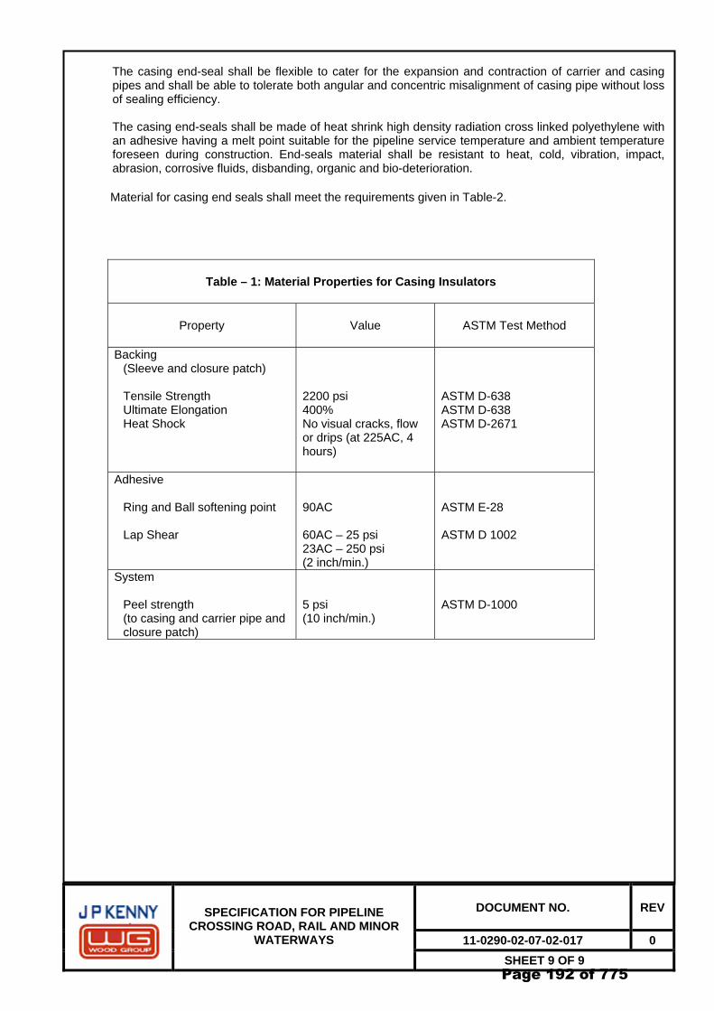
6.4 Air Volume Calculation
In order to check the presence of air in the pipeline, two separate consecutive pressure lowering of 0.5 bar shall be carried out.
Page 131 of 775
DOCUMENT NO. REV
11-0290-02-07-02-020 0
SPECIFICATION FOR HYDROTESTING OF PIPELINES
SHEET 9 OF 16
For calculation of air in the pipeline the second pressure lowering shall be used, and the relevant drained water shall be accurately measured (V1). This amount measured shall be compared to the theoretical amount (V2) corresponding to the pressure lowering that has been carried out, by using the procedure outlined in the specification.
If no air is present in the length under test:
V1 --- = 1 V2
The above ratio is acceptable, provided it shall not differ from ‘1’ by more than 6% (i.e. 1.06).
If ratio is found to be above within limits, then pressurization can proceed. If not, water refilling shall be carried out by another run of batching pigs after depressurizing the pipeline.
Simultaneously contractor shall also construct a plot of pressure volume from the initial stage of pressurization until a definite linear relationship is obtained. The theoretical P/V plot shall also be plotted on the same graph. Once 50% of test pressure is reached, the linear curve shall be extrapolated backwards to cut the volume axis. The measured air volume and its percentage of pipeline test section volume shall be calculated. On completion of the air inclusion P/V plot, a separate P/V plot should commence and continue until the test pressure is reached. The slopes of the actual P/V plot and theoretical P/V plot shall be compared and all calculations and graphs shall be submitted to Owner/Consultant for information.
6.5 Testing (pressure holding test)
After the section has been pressurized and the air column test has given acceptable results the test pressure shall be held for a minimum of 48 hours (24 hours for strength test and 24 hours for leak test) after stabilization for 24 hours. After temperature and pressure are stabilized, (for the 24 hours leak test) the injection pump shall be disconnected and all connections at the test heads shall be checked for leakage. The pressure and temperature recorders shall then be started once again with the charts in a real time orientation for continuous recording throughout the test duration. No further pumping is permitted during the test period. During the testing period the following measurements shall be recorded/reported:
- Every one-hour pressure measurements from dead weight testers.
- Every two hours the ambient temperature and the pipe temperature at the thermocouples and
fill water temperature. - Barometric pressure for every one hour. All data shall be recorded on appropriate formats attached to the hydrostatic test procedure manual. Care shall be taken that the maximum test pressures are not exceeded. If the water temperature increases resulting in increased test pressure above maximum test pressure limits, then bleeding of water shall be done to bring the test pressure within limits. Bleed-off water shall be accurately measured and recorded.
7.0 ACCEPTANCE
The hydrostatic test shall be considered as positive if pressure has kept a constant value throughout the test duration, except for change due to temperature effects. Such changes shall be evaluated as described below.
The pressure change value as a function of temperature change shall be algebraically added to the pressure value as read on the meters. The methodology for calculation of pressure change due to
Page 132 of 775
DOCUMENT NO. REV
11-0290-02-07-02-020 0
SPECIFICATION FOR HYDROTESTING OF PIPELINES
SHEET 10 OF 16
temperature shall be as per section 9.0 of this specification. The pressure value thus adjusted shall be compared with the test and shall be considered as acceptable if the difference is less than or equal to 0.2% of test pressure. In case of doubt or if for any reason the test pressure has been reduced other than for bleed-off excess pressure, the test duration shall be extended by 24 hours.
If test section doesn’t meet the above requirement, Contractor shall determine by search the location of
leakage or failure. All leaks and failures within the pipe wall or weld seam shall be repaired by replacement of entire pipe or pipes in which leakage or failure occurs. In those cases, where leaks occur in circumferential welds the Owner/Consultant shall determine the method of repair. Contractor shall comply with instructions of the Owner/Consultant’s representative whether to replace a section of the line pipe that includes the line leak or whether to repair the circumferential weld. The repair shall be carried out as per specifications. Where failures occur in pipeline field bends, bends shall be replaced with same degree bends. After completion of repairs, the hydrostatic test shall be repeated as a complete cycle, as per this specification. All repairs and retesting shall be carried out at the expense of the Contractor. All work of reinstalling line pipes to replace failed pipes shall be carried out as per specifications. For Owner/Consultant verification, all failed pipes shall be stored, marked, and tagged indicating date and location of failure and pressure at which failure occurred. The failed areas shall be greased to prevent corrosive action.
8.0 TERMINATION
After the positive results of testing and all the data have been gathered, the test shall be terminated upon written approval given by Owner/Consultant.
The pipeline shall be slowly depressurized at a moderate and constant rate as instructed by Owner/Consultant.
Contractor shall dispose of test water in a responsible manner to the satisfaction of the local authorities, client and contiguous property owners. There shall be minimum damage to environment and shall not result in any ground water contamination.
All thermocouples installed on the line shall be removed and coating repaired to satisfaction of the client. All piping and instrument connections shall be blanked, plugged or capped as per requirements.
9.0 CALCULATIONS
The theoretical water amount that is necessary for filling the section to be tested shall be obtained from the geometrical volume of the section considering the pipe tolerances.
The theoretical water amount that is necessary for pressurizing the section shall be calculated by
means of the following formula:
Vp = (0.884 r1/t+A) x 10-6xVtxΔPxK Where: Vp = computed water amount required to raise the pressure by ‘ΔP’ in the section to be tested (m3) Vt = geometrical volume of the section (m3) ΔP = Pressure rise (bar) r1 = nominal inner radius of the pipe (mm) t = nominal pipe thickness (mm)
Page 133 of 775
DOCUMENT NO. REV
11-0290-02-07-02-020 0
SPECIFICATION FOR HYDROTESTING OF PIPELINES
SHEET 11 OF 16
A = isothermal compressibility value for water at the pressurization temperature in the P range (bar-1).
K = a dimensionless coefficient that is equal to a value of 1.02 for Longitudinally welded
pipe, and 1.0 for seamless pipe. The pressure change due to a water temperature change shall be calculated through the following
formula: ΔP = B * ∆T / { ( 0.884 r1 / t )+ A } Where; ΔP = Pressure change resulting from a temperature change (bar). ΔT = Algebraic difference between water temperature at the beginning of the test and water
temperature as measured at the end of the test (ºC). B = Value of the difference between the thermal expansion of water at the pressure and
temperature as measured at the end of the test and that of Steel (ºC). Refer Table-1. A = Isothermal compressibility value of water as estimated at the pressure and temperature
values obtained at the end of test (bar–1). r1 = nominal inner radius of the pipe (mm). t = nominal pipe thickness (mm).
10.0 TEST REPORT / DOCUMENTATION
A complete report signed by Contractor and the Owner/ consultant Representative shall be submitted upon completion of the hydrostatic testing operations for each test section.
The report shall contain as minimum:
- Cleaning, flushing, filling and testing procedure used - Schematic layout of cleaning, filling and testing facilities
- All Instruments calibration certificates
- A profile of the pipeline that shows the test sites, all instrument and injection connections.
- Pipe filing logs and records. - Hydrotest chemicals specification, dosage, injection records specifications and certificates. - Pig specifications - Pigging records including details of pig runs. - Pressurisation and stabilisation records and charts with all information specified. - Pressure and temperature recording charts with appropriate information inscribed thereon. - Dead weight tester logs and recordings - Air volume calculations and plots
Page 134 of 775
DOCUMENT NO. REV
11-0290-02-07-02-020 0
SPECIFICATION FOR HYDROTESTING OF PIPELINES
SHEET 12 OF 16
- Pressure – temperature change calculations - Profiles of pipelines with elevations - Environmental data, barometric data - Depressurisation logs and records - Disposal method of test water - Records and photograph of all leaks/failure, location of failure and method of repair - Schematic isometric drawing of test header with all auxiliaries. - Daily log of events.
11.0 PRECAUTIONS DURING THE TEST
In addition to all that has been expressly described in the procedures for carrying out the test, the following requirements shall also be complied with.
11.1 During the hydrotest, no other activities shall be performed on or near pipeline being tested. Further, the
test sections shall be kept under continuous surveillance by regular patrols during test and with continuous communication.
11.2 Signs stating “PIPE UNDER TEST – KEEP OFF” shall be placed where the test ends are located. Such
areas shall be suitably guarded throughout the duration of the test. In case pressurizing is done from the shore end, the entire operational area shall suitably be fenced to prevent entry of unauthorized personnel. The warning sign shall also be in Local Language.
11.3 All personnel working on the hydrotest spread shall be instructed on the possible dangers connected
with the high-pressure test operations. During the testing, operations, unauthorized personnel shall not be allowed near by the test head location. Test cabin shall be atleast 10 m away from the pipeline so that it is not affected by any pipeline failure.
11.4 All precautions pertaining to handling and disposal of chemicals shall be as per manufacturer’s
standards.
11.5 All pumps shall have overprotection devices set @ 5 bar g above test pressure.
11.6 The pressure shall be reduced to a safe level of 1 bar g before any work is permitted on the pipeline section.
11.7 All crossing areas and areas of public access should be patrolled during test.
11.8 Contractor to ensure that all safety precautions comply with statutory and other national/state and local regulations and shall give notice to the concerned authorities regarding the intention to carry out the test.
11.9 Contractor to ensure that a hydrotest organisation chart is made and all personnel are fully aware of
their responsibilities and scope of work.
Page 135 of 775
DOCUMENT NO. REV
11-0290-02-07-02-020 0
SPECIFICATION FOR HYDROTESTING OF PIPELINES
SHEET 13 OF 16
Table 1:Difference between the water thermal expansion factor and the steel thermal expansion factor (ºC-1).
3.0 CLEANING AND DRYING.......................................................................................................................3
Page 141 of 775
DOCUMENT NO. REV
011-290-02-07-02-021 0
SPECIFICATION FOR DRYING AND CLEANING OF PIPES
SHEET 3 OF 5
1.0 SCOPE
This specification covers the minimum requirements to be followed by the contractor in carrying out cleaning and drying operation of pipeline after testing.
2.0 DEFINITIONS
For this specification the following definitions shall apply:
OWNER/CONSULTANT : GAIL (GAS) LIMITED CONSULTANT : WOOD GROUP ENGINEERING INDIA PVT. LTD. (WGI) CONTRACTOR : The Company named as such in the Contract. SHALL/MUST/IS TO BE : A mandatory requirement
SHOULD : A non-mandatory requirement, advisory or recommendation
3.0 CLEANING AND DRYING
3.1 Pipe Construction
For pipeline construction once the test (resistance and leak test) results have been declared satisfactory, the cleaning and drying operations shall be carried out. The pipeline section to be cleaned and dried is to be sealed at the ends by means of welded testing pig traps. These end stations are equipped with instruments for permanent measurement of the temperature, pressure and dew point. After de-watering, conventional pigs and foam pigs shall be run through the pipelines as many times as necessary until internal surface is free of dirt, such as welding slags, rust, oil and dust particles. The compressors used to draw the pigs shall have an absorption drying units with adequate dew point outlet. After having measured a constant dew point of -80 C during the last run, the pipeline is closed for at least 24 hours.
Except otherwise specified the dew point is fixed at -80C, during this time the dew point is measured every 4 hours. If the dew point has not increased after 24 hours, the pipeline is considered dry. It is left at 0.2 bar overpressure dry air or under Nitrogen. Dew point measurements are carried out under the supervision of and in consultation with the Owner / Owner’s Representative at the other end from the drying installation. The Contractor shall only use oil – free and soundproofed compressors for supply to the drying units. When venting the pipeline sections, there shall always be a Contractors staff present and the public authorities concerned shall be informed by the Contractor.
3.2 Dewatering and Swabbing Of Pipeline
Dewatering of a pipeline section shall be done to facilitate EGP / calliper pigging. During the dewatering operation, the major quantity of water shall be removed from the main pipeline.
The disposal of the water shall be performed such that no harm is done to the environment and the dewatering procedure, to be submitted by the pipeline contractor for Company/Company’s representative’s approval, should indicate this safe disposal methodology.
The Swabbing operation shall consist of running several suitable foam pig trains using air as propellant through the pipeline. This is done by operating numerous swabbing pigs so that the weight increase in pig before & after the swabbing driving operation is not more than 25%. During swabbing operation, the residual free water content in the pipeline shall be reduced to an acceptable lower value for EGP.
Page 142 of 775
DOCUMENT NO. REV
011-290-02-07-02-021 0
SPECIFICATION FOR DRYING AND CLEANING OF PIPES
SHEET 4 OF 5
It is the responsibility of the pipeline contractor to develop a suitable dewatering and swabbing procedure and submit the same for Company/ Company’s representative’s approval. Operational Requirements
The pipeline contractor may use suitable dewatering for pipeline dewatering purpose. In such case, at least two dewatering pig runs is to be completed with air as propellant. The pipeline contractor shall provide suitable compressor for dewatering and swabbing.
Sealing pigs shall be used and will be suitable for traversing the whole length of the pipeline segment being dewatered, without damaging the internal pipe-wall.
If dewatering pigs are used, the minimum speed and the backpressure of the pigs to be maintained during dewatering operation shall be proposed by the pipeline contractor to do continuous operation and without pig getting stuck.
Upon arrival of the pigs at the receiving end, the pipeline contractor in the presence of Company/Company’s representative shall remove the pigs without delay.
For swabbing, suitable foam pigs shall be used by pipeline contractor and will be suitable for traversing the whole length of the pipeline segment being swabbed. Before starting swabbing operation, the pipeline contractor has to weight the swabbing pigs and record the weight. On arrival of the pigs at the receiving, the pipeline contractor should judge the weight gained by the swabbing and shall again weight the pigs. Acceptance Criteria
Before proceeding to the next stage of operation, the pipeline contractor shall ensure that bulk of the water has been removed from the pipeline system and swabbing is done to meet the requirement of EGP. Note-1: After dewatering and swabbing of the main pipeline segment, other Contractor shall carry out
Electronic Geometry Pigging (EGP) / calliper pigging of the pipeline.
Note-2: Ideally, EGP / calliper pigging shall be followed by commissioning activities of the pipeline. If subsequent to EGP activities, commissioning activities of the pipeline is taken up after long time delay then adequate measures should be taken to preserve the pipeline during this idle period so that internal corrosion does not occur. Suitable preservative fluid should be introduced in the pipeline and the pipeline should be kept bottled up with this preservative inside it.
3.3 Drying
Unless otherwise stipulated the piping shall be dried with compressed air. The compressors used for drying shall have an absorption drying units with adequate dew point outlet.
Valves shall be drained as much as possible in the half – open position under air pressure through the vent pipes under the supervision of and in consultation with the Owner / Owner’s Representative. Manipulation of the valves without the supervision of the Owner / Owner’s Representative is strictly forbidden. The blowing shall be continued until a constant dew point of -80 C (or other dew point as per TS) is measured. Subsequently, the pipe shall be closed for 24 hours. If the dew point has not increased after 24 hours, the installation is considered dry.
• The piping to be dried must have the necessary measuring devices to measure constantly the temperature, pressure and dew point.
• The piping is considered dry if following several measurements in 24 hours and at several branches of the pipe the dew point measurements are constant and the desired value is not exceeded.
Page 143 of 775
DOCUMENT NO. REV
011-290-02-07-02-021 0
SPECIFICATION FOR DRYING AND CLEANING OF PIPES
SHEET 5 OF 5
For faster drying, the Contractor may propose drying with heated Nitrogen. The temperature shall be limited to +500 0C.
Page 144 of 775
GAIL GAS LIMITED
CITY GAS DISTRIBUTION PROJECT
CLIENT JOB NO. - SPECIFICATION FOR INSPECTION AND TESTING OF
PRODUCTION WELD TOTAL SHEETS 06
DOCUMENT NO 11 0290 02 07 02 023
0 16.10.09 ISSUED FOR TENDER GV AP SB
B 25.08.09 ISSUED FOR CLIENT’S COMMENTS BG AP SB
A 24.08.09 ISSUED FOR IDC BG AP SB
REV DATE DESCRIPTION PREP CHK APPR
1Page 145 of 775
DOCUMENT NO. REV
11-0290-02-07-02-023 0
SPECIFICATION FOR INSPECTION AND TESTING OF PRODUCTION WELD
4.0 TESTING OF WELDED JOINTS AND ACCEPTANCE CRITERIA..............................................................3
5.0 IMPLEMENTATION OF THE NON-DESTRUCTIVE TESTS........................................................................5
6.0 ANNOUNCEMENT OF TEST RESULTS......................................................................................................5
7.0 INSPECTION OF FILMS BY CONTRACTOR...............................................................................................6
8.0 LOCAL REPAIRS AND CUTOUT DEFECTIVE WELDS .............................................................................6
Page 146 of 775
DOCUMENT NO. REV
11-0290-02-07-02-023 0
SPECIFICATION FOR INSPECTION AND TESTING OF PRODUCTION WELD
SHEET 3 OF 6
1.0 PURPOSE
This Specification defines the minimum technical requirements for the various activities to be carried out by Contractor for Inspection & Testing of Production Weld.
2.0 DEFINITION
For this specification the following definitions shall apply: OWNER - GAIL (GAS) LIMITED CONSULTANT - WOOD GROUP ENGINEERING INDIA PVT. LTD. (WGI) CONTRACTOR - The Company named as such in the deed. SHALL/MUST/ISTO BE - A mandatory requirement SHOULD - A non-mandatory requirement, advisory or recommendation.
3.0 GENERAL
Except otherwise stated by the Owner / Consultant for the number of field butt welds selected for non-destructive examination the ASME B 31.8 shall govern.
The Consultant shall determine the non-destructive examination method applicable and their specific field application.
The Owner / Consultant shall supervise and inspect the welding activities in accordance with the provisions laid down in the Codes.
The Owner / Consultant is also exclusively responsible for its personal interventions and decisions as supervisor and inspector of the welding activities.
Except otherwise stated by the Owner and the Consultant. The inspection and testing of production welds will be carried out in accordance with the provisions of the ASME B 31.8 code and the standard mentioned in this chapter.
4.0 TESTING OF WELDED JOINTS AND ACCEPTANCE CRITERIA
The welded joints shall be tested prior to painting or coating.
4.1 Non – destructive testing
4.1.1 Visual Inspection
The visual inspection shall be interpreted in accordance with API 1104 with the following additional requirements:
• Arc ignition Points
o ≤ 0.5 mm: acceptable if ground out
o > 0.5 mm: unacceptable and cut out
• Clamp Crates
o ≤ 0.5 mm: acceptable if ground out
o 0.5 mm – 1.5 mm: acceptable if ground out and welded according to repair procedure.
Page 147 of 775
DOCUMENT NO. REV
11-0290-02-07-02-023 0
SPECIFICATION FOR INSPECTION AND TESTING OF PRODUCTION WELD
SHEET 4 OF 6
o > 0.5 mm: unacceptable and cut out
4.1.2 Radiographic Testing
4.1.2.1 Test method and acceptance criteria
Radiographic testing with X rays or gamma rays shall be carried out in accordance with the provisions of API Std 1104.
4.1.3 Ultrasonic Testing
4.1.3.1 Test Method and Acceptance criteria
The ultrasonic testing shall be carried out in accordance with ASME V-Art. 5 and API 1104.
The number of field joints welds selected for ultrasonic examination is specified by the Owner / Consultant.
4.1.3.2 Scope of the Test
a) Minimum test planned
• For the stations and valves stations all welds shall be inspected by ultrasonic testing.
• Welded joints, which are welded using external clamps (e.g. tie-in welds) shall be 100% ultrasonically tested.
b) Supplementary Tests
Further to a decision by the Owner / Consultant (for example in the event of cracks) all the welds carried out in the course of that day may be tested with ultrasonic testing and if necessary this inspection may be extended to all welds. If these tests bring to light any defective welds, the Contractor shall carry out the repairs at his own expense.
4.2 Other test method
As well as the non-destructive tests describe above, the Owner / Consultant, decide to carry out additional destructive or non-destructive tests, such as:
• Magnetic Particle Test
• Liquid Penetrant test
• Weld Sampling
• Any other destructive or non – destructive test methods
The acceptance criteria for the magnetic partial test and liquid penetrant test are defined on the basis of the following standards:
• Magnetic particle test
o Method: ASME V-Art 7
o Acceptance criteria ASME VIII Div 1 – App 6 and API 1104.
• Liquid penetrant test
o Method: ASME V-Art 6
Page 148 of 775
DOCUMENT NO. REV
11-0290-02-07-02-023 0
SPECIFICATION FOR INSPECTION AND TESTING OF PRODUCTION WELD
SHEET 5 OF 6
o Acceptance criteria ASMEVIII – Div 1 – APP 8 and API 1104
The acceptance criteria for the weld samples shall be the same as for the welding procedure qualification.
4.3 Destructive test
At least one production weld (to be checked by Owner / Consultant) will be cut out during the first week of welding production and sent for destructive testing. Other production welds (Cut-out) to be sent for destructive testing shall be chosen by Owner / Consultant. The frequency of other production weld shall be one joint / 05 km with a minimum of 50 cm of material on either side of the weld.
Contractor will not be entitled for any type of compensation for any destructive test deemed necessary by Owner/ Consultant.
The destructive testing shall be carried out in accordance with section 5.6 of API 1104. All tests shall be carried out in Owner /Consultant approved laboratory.
5.0 IMPLEMENTATION OF THE NON-DESTRUCTIVE TESTS
Radiographic tests will be carried out daily after the completion of the welding on the day’s welding pipeline stretch.
No tests shall be carried out on strings, which are still being welded even if the usual deadlines are compromised as a result.
Ultrasonic tests shall in principle be carried out 24 hours after welding.
6.0 ANNOUNCEMENT OF TEST RESULTS
The NDT results shall be sent to contractor by Owner / Consultant / TPI during normal working hour in the following day as agrees with Owner.
6.1 Welding of tie-ins and repairs
6.1.1 Radiographic Testing
Subject to the approval of the Owner / Consultant, in urgent cases, TPI shall inform the Contractor verbally of the provisional test results within the hour following the photograph by interpreting the wet film.
The results shall not be definitive until the dry firm has been examined.
The deadline for verbal communication of he definitive results shall be twelve hours following the announcement of the results when they have been interpreted from the wet film.
6.1.2 Visual and ultrasonic Testing
The results of these tests shall be given verbally at the time of the test.
Written communication of he results shall be carried out n the same way as described in clause 6.0.
Page 149 of 775
DOCUMENT NO. REV
11-0290-02-07-02-023 0
SPECIFICATION FOR INSPECTION AND TESTING OF PRODUCTION WELD
SHEET 6 OF 6
7.0 INSPECTION OF FILMS BY CONTRACTOR
Before carrying out any repairs, the Contractor may inspect the relevant film himself. The film remains the property of the Owner.
8.0 LOCAL REPAIRS AND CUTOUT DEFECTIVE WELDS
8.1 General
The Contractor shall be obliged to repair welds or re-weld or cut out welds which are deemed defective by the TPI. This shall be carried out within normal working hours.
Each repair of defective weld, whether local or total, shall be carried out with two working days following the announcement of the results by TPI.
Section 10 of API 1104 is applicable with the following requirements.
All cracks other than carter cracks or star cracks (ref 9.3.10 of API 1104) shall not be repaired by welding. The cracks must be removed by cutting out the weld.
All other defects except superficial defects detected by NDT can only be repaired by welding after approval by TPI on site.
Superficial defects can be removed by grinding provided min. thickness of pipe is respected. After grinding, the ground area will be inspected by liquid penetrant test or magnetic particle test.
The weld repairs shall be tested by X-rays, UT and / or MT as required by TPI at site.
A second repair on weld is not acceptable and weld must be cut out if defects are detected in repair.
Incase of cut out of weld, & zone of at least 5 cm of the pipe material shall be removed on both side of the weld. The new bevel should be checked by penetrant test in the absence of defect.
The cut out welds shall be preserved in the weld number for further investigation.
Page 150 of 775
GAIL GAS LIMITED
CITY GAS DISTRIBUTION PROJECT
CLIENT JOB NO. - SPECIFICATION FOR PIPELINE MARKERS
REFERENCE DRAWINGS:- WOODGROUP ENGINEERING INDIA PVT. LTD STANDARD DRAWINGS 1-07-010 : PIPELINE WARNING SIGN 1-07-011 : DIRECTION MARKER 1-07-013 : K.M. POST 1-07-015 : AERIAL MARKER 1-07-016 : NAVIGABLE WATERWAY PIPELINE CROSSING WARNING SIGN 1-07-017 : TYPICAL ROW BOUNDARY MARKER
Page 152 of 775
DOCUMENT NO. REV
11-0290-02-07-02-024 0
SPECIFICATION FOR PIPELINE MARKERS
SHEET 3 OF 4
1.0 SCOPE
1.1 This specification covers the minimum requirements for supply, fabrication and erection of pipeline markers to be installed by CONTRACTOR at various locations along the route of the pipeline.
1.2 This specification shall be read in conjunction with the conditions of all specifications and documents
included in the CONTRACT between OWNER and CONTRACTOR.
2.0 REFERENCE CODES
Reference has been made in this specification to the latest revision of the following code: API RP 1109 : Recommended practice for marking liquid petroleum pipeline facilities.
3.0 GENERAL
3.1 CONTRACTOR shall supply, fabricate and install the pipeline markers along the pipeline route as per WOODGROUP ENGINEERING INDIA PVT. LTD. standard drawings. The locations of markers as indicated in the approved drawings shall be treated for guidance purposes only and the exact location of the markers shall be based on AS BUILT drawing and as directed by the OWNER.
3.2 The pipeline markers shall be fabricated and installed in accordance with the standard drawings
included herein. Before start of fabrication of the markers, CONTRACTOR shall prepare and submit for OWNER’S approval the detailed scheme for the marker plates as applicable for the project.
3.3 The pipeline markers shall be installed, as far as possible, at locations such that they do not cause any
hindrance to the regular use of the land or to the traffic.
4.0 AERIAL MARKERS
Aerial markers shall in general be installed along the pipeline at every five (5) kilometres intervals and at places specified by OWNER. Refer Standard Drawing No. 1-07-015 for details.
5.0 KILOMETRE MARKERS
Kilometre markers shall in general be installed along the pipeline between the aerial markers at every one (1) kilometre interval. Markers shall indicate cumulative chainage in kilometres from the reference station, as directed by OWNER. A kilometre marker is not required if the relative length between its location and any pipeline warning sign is less than 200 metres. Refer Standard Drawing No. 1-07-013 for details.
6.0 PIPELINE WARNING SIGN
Pipeline Warning Sign shall in general be installed at • National, State Highway & Other Road Crossings (above 15m width) : 2 Nos. Min. • Other Road Crossings (less than 15m width) : 1 No. Min. • Railway Crossings : 2 Nos. Min. • Water Crossings (less than 15m width) : 1 No. Min. • Water Crossings (above 15m width) : 2 Nos. Min. • SV Stations & TOP Station : 1 No. Min.
Page 153 of 775
DOCUMENT NO. REV
11-0290-02-07-02-024 0
SPECIFICATION FOR PIPELINE MARKERS
SHEET 4 OF 4
• And at any other location of importance as observed by OWNER /OWNER’S Representative during construction.
Pipeline Warning Sign shall identify the existence of the pipeline and display the name of the
COMPANY, with an emergency telephone number, as shown in Standard Drawing No. 1-07-010 for details.
7.0 ROW BOUNDARY MARKERS
Right-of-Way boundary markers shall be fabricated and installed as per the drawings at every 250 metres interval along the entire pipeline route. These shall be installed on either side of the pipeline route to define the ROW boundary limits. These shall also be installed at pipeline turning points to maintain the continuity of the ROW limits. Refer WOOD GROUP ENGINEERING INDIA PVT. LTD Standard Drawing No. 1-07-017 for details.
8.0 DIRECTION MARKERS
Direction markers as shown in WOODGROUP ENGINEERING INDIA PVT. LTD Standard Drawing No. 1-07-011 shall be installed to identify the significant turning points of the pipeline during serial traverse. One direction marker shall be installed at each turning point along the pipeline alignment. Two more directional markers shall be installed along the Pipeline alignment on either side of the Turning Point at 200 m from Turning Point of the pipeline route.
The Navigable Waterway Pipeline Crossing Warning Sign shall be fabricated in accordance with Standard Drawing No. 1-07-016 Such Warning Sign shall be installed one on each bank of navigable water courses at the pipeline crossing location, in lieu of the Pipeline Warning Sign described in clause 6.0 of this specification.
13.0 DISPOSAL OF DETERIORATED EXPLOSIVES ................................................................................... 9
Page 156 of 775
DOCUMENT NO. REV
11-0290-02-07-02-025 0
SPECIFICATION FOR CONTROLLED ROCK BLASTING
SHEET 3 OF 9
1.0 SCOPE
1.1 This specification covers the minimum requirements for materials, personnel, transportation, storage and use of explosives for grading of Right of Use (ROU) and excavation of trenches for the burial of pipelines in rocky terrain.
1 .2 This specification does not cover the construction or operation of permanent magazines.
2.0 REFERENCE DOCUMENTS
2.1 The following National and International regulations and codes shall be used: BS 5607 : Safe use of Explosives in the Construction Industry NFPA-495 : Manufacture, Transportation, Storage & Usage of Explosive Materials. IS 4081 : Safety Code for Blasting and related drilling operations
Applicable Safety Rules of CCOE, Nagpur
2.2 Definitions For this specification the following definitions shall apply:
OWNER - GAIL (GAS) LIMITED CONSULTANT - WOOD GROUP ENGINEERING INDIA PVT. LTD. (WGI) CONTRACTOR - The Company named as such in the deed. SHALL/MUST/IS TO BE - A mandatory requirement SHOULD - A non-mandatory requirement, advisory or recommendation
3.0 GENERAL
3.1 The CONTRACTOR shall acquaint himself and comply with all the applicable local laws and regulations concerning storing, handling and the use of explosives. All such laws, regulations and rules etc., as enforced from time to time shall be binding upon CONTRACTOR. National/Local Laws and regulation shall take precedence over this specification in the event of conflict. All conflicts shall be brought to the notice of the OWNER.
3.2 The requirements stated herein however in no way relieve the CONTRACTOR of his responsibility of
carrying out safe blasting operations and shall be solely responsible for damages and claims thereof.
3.3 The use of explosives requires an approval from the Chief Controller of Explosives and/or his authorized Inspector. It shall be the responsibility of the CONTRACTOR to obtain all such permits and observe all requirements regarding the safe storage, handling and use of explosives. All expenses incurred in this regard shall be to CONTRACTOR’s account.
3.4 Contractor shall inform the OWNER in writing at least four (4) weeks prior to planned use of
explosives. 3.5 Contractor shall notify the OWNER prior to any blasting in the proximity of overhead power lines,
roads, communication lines, pipelines, utility services or other services and structures above and below ground. Before, starting blasting operations, local authorities and owners of utilities shall be
Page 157 of 775
DOCUMENT NO. REV
11-0290-02-07-02-025 0
SPECIFICATION FOR CONTROLLED ROCK BLASTING
SHEET 4 OF 9
consulted to check on the presence of services which could be damaged and their approval obtained to undertake blasting operations. The distances to nearest structures (houses, offices, factories) or service shall also be taken into consideration when planning blasts so that ground vibration and air-over pressure is kept within acceptable levels as given in section 11.0 of this specification.
3.6 CONTRACTOR shall prepare an Explosives Handling and usage Procedure for the information of the
OWNER which shall incorporate the following: - Detailed procedure and calculations - Nature of blasting operations, including hole diameter, depth and presence of cavities. - Rock characteristics. - Type of explosives.
- Temperature likely to be encountered in use.
3.7 Unless specified otherwise, blasting shall not be allowed within 20 m of any above ground or underground structure, Pipelines or other facilities. However, in case it is necessary to carry out blasting operation with in 20m from any under ground or above ground structures, Pipelines or other facilities, the blasting may be allowed, at discretion of Owner, subjected to the following:
a) Minimum clear distance from the facility is 5 m. b) Contractor Demonstrates the blasting technique proposed by him doesn’t result in any
damage to existing facility. (Contractor shall carry out mock demonstration as per the direction of the Owner/Consultant for this purpose).
c) Contractor fulfils the condition laid out by the Owner of existing facilities.
d) Contractor fulfils the requirement laid out by the National / Local Laws and Regulations and
other statutory / regulatory Authorities.
In case of presence of overhead power lines/cables, specific approval shall be obtained by Contractor from the concerned Authorities having jurisdiction over it.
4.0 MATERIALS
4.1 All materials such as explosives, detonators, fuses, tamping materials etc. that are proposed to be used by the CONTRACTOR in blasting operations, shall be as Approved for use in the Country.
4.2 All electric detonators used in the blast shall be of the same electrical sensitivity and be
produced/procured from the same manufacturer.
4.3 The detonators used shall be capable of giving effective blasting of the explosives. Damaged explosive materials shall be destroyed by a responsible person as per manufacturer’s instructions or returned to the manufacturer.
4.4 No explosive material shall be abandoned.
4.5 All blasting materials and testing equipment shall be regularly tested for correct performance. The
intervals between tests shall be decided after consideration of the local factors, but tests shall always be carried out if the blasting materials and/or test equipment have been subjected to abnormal conditions, or following misfires. Guidelines/recommendations of the manufacturer shall be adhered to.
Page 158 of 775
DOCUMENT NO. REV
11-0290-02-07-02-025 0
SPECIFICATION FOR CONTROLLED ROCK BLASTING
SHEET 5 OF 9
4.6 All packaging and other waste materials gathered together during blasting operation shall be burnt after the blast has been fired. The burning site shall be chosen at a safe distance with due respect to prevailing wind strength and direction, at least 100 meters from explosives stores and other premises. A minimum of two fire extinguishers shall be on hand during burning activities.
5.0 PERSONNEL
5.1 Excavation by blasting will be permitted only under personal supervision of competent and licensed persons and by trained workmen.
5.2 The storage of explosives shall be in the charge of a person approved by the OWNER. OWNER may,
if necessary, ask police inquiries being made as to his reliability, antecedents etc.
6.0 STORAGE OF EXPLOSIVES
6.1 The CONTRACTOR shall build a magazine for storing the explosives. The site of the magazine, its capacity and design shall be subject to approval by the OWNER and the Inspector of Explosives before the fabrication is taken up. As a rule the explosives should be stored in a clean, dry, well ventilated, bullet proof and fire proof building, at an isolated site. Adequate security shall be provided to ensure no unauthorized entry into the magazine. A notice shall be hung next to magazine entrance prohibiting entry of unauthorized persons.
6.2 CONTRACTOR shall comply with National/Local Regulations and specifications for truck mounted
mobile explosives store. Mobile stores shall only carry ONE Day’s Explosives requirements and shall be parked overnight inside the compound at the authorized magazine.
6.3 All safety precautions and necessary equipment for maintenance, operation of mobile stores, as
required by local authorities or regulatory bodies shall also be installed/provided on the Mobile Store.
6.4 A careful and day-to-day account of all explosives shall be kept by the CONTRACTOR in a register and in an approved manner. The register shall be produced by the CONTRACTOR, for the inspection of the OWNER / Inspector of Explosives when so required by the later. Any loss, damage or theft shall be reported immediately to the necessary local authorities and to the OWNER.
6.5 The magazine shall on no account be opened during or on the approach of a thunderstorm and no
person shall remain in the vicinity of the magazine during such period.
6.6 Magazine-shoes without nails shall, at all times, be kept in the magazine, and a wood-tub or cement trough, filled with water shall be fixed near the door of the magazine.
6.7 Persons entering the magazine must put on the magazine-shoes.
I) Not to put their feet on the clean floor unless they have magazine-shoes on.
II) Not to allow the magazine-shoes to touch the ground outside the clean floor.
III) Not to allow any dirt or grit to fall on the clean floor.
6.8 No matches or inflammable material shall be allowed in the magazine. Light shall be obtained from an electric storage battery lamp.
6.9 No person having articles of steel or iron on him shall be allowed to enter the magazine. No tools or
implements other than those of copper, brass, gun metal or wood shall be allowed inside the magazine.
Page 159 of 775
DOCUMENT NO. REV
11-0290-02-07-02-025 0
SPECIFICATION FOR CONTROLLED ROCK BLASTING
SHEET 6 OF 9
Oily cotton, rags, wastes and articles liable to spontaneous ignition, shall not be allowed inside the magazine.
6.10 Boxes of explosives shall not be thrown down or dragged along the floor and shall be stacked on
wooden trestles. Open boxes of explosives shall never be exposed to the direct rays of the sun. Empty boxes or loose packing materials shall not be kept inside the magazine.
6.11 The magazine shall have a lightning conductor, which shall be got tested at least periodically, by an
officer authorized by the OWNER, the testing fee shall be to the CONTRACTOR’s account.
6.12 The magazine shall be inspected periodically by an officer representing the OWNER, who will see that all the rules are strictly complied with. He will notify all omissions etc. to the CONTRACTOR, who shall rectify the defects within a period of 3 days from the date of receipt of the notice, failing which the OWNER may take whatever actions it considers suitable.
7.0 PREPARATION OF EXPLOSIVES
7.1 CONTRACTOR shall submit the following procedure for INFORMATION of the OWNER as a minimum.
- Loading of explosives - Drilling of new holes and extending existing holes - Handling of explosives at site - Tamping explosives into holes - Machines, tools and cables required - Initiation of blasting - Safety of personnel - Vibration control - Blast pattern and shot size establishment - Misfires - Emergency procedures
7.2 Trial blasts in conjunction with vibration recording shall be carried out for each rock and trench type, in order to assess rock breakability and vibration levels. These trial blasts shall be carried out prior to actual trench blasting of the pipeline route. CONTRACTOR shall conduct trial digs as directed by OWNER in order to check suitability of the blasting pattern and to measure vibration levels to ensure vibration levels are below the allowable maximum.
7.3 “Weight per Distance Tables” shall be drawn up from these trials.
7.4 The detonators shall never be forced into the primer cartridge. It shall be inserted in a hole made by a
wooden, copper, brass or aluminium pricker. The detonator shall be firmly embedded in the primer so that it is not pulled out of place during loading.
7.5 Detonators shall be activated electrically. In proximity of electric over-head power lines,
CONTRACTOR may use non-electric system with the approval of OWNER. Fly rock shall be minimized by the use of approved blast mats and by careful selection of shot size and drill hole configuration.
Page 160 of 775
DOCUMENT NO. REV
11-0290-02-07-02-025 0
SPECIFICATION FOR CONTROLLED ROCK BLASTING
SHEET 7 OF 9
7.6 Use of explosives is prohibited in areas exposed to flammable gases or dust.
7.7 Explosive and detonators shall be carried in separate boxes, tightly closed, and transported
separately. For the conveyance of primers special containers shall be used.
7.8 Explosives shall be stored and used chronologically to ensure that the ones received earlier are being used first.
7.9 A make-up house shall be provided at each working place in which cartridges shall be made up by
experienced men as required. The make-up house shall be separated from other buildings. Only electric storage battery lamps shall be used in this house.
7.10 No smoking shall be allowed in the make-up house.
8.0 PREPARATION OF PRIMERS
The primers shall not be prepared near open flames or fires. The work of preparation of primers shall always be entrusted to the qualified and approved personnel. Primers shall be used as soon as possible after they are ready.
9.0 CHARGING OF HOLES
9. 1 The work of charging shall not commence before all the drilling work at the site is completed and the OWNER has satisfied itself to that effect by actual inspection.
9.2 The lead wires shall be kept away from conductors or sources of stray current. While charging, open
lamps/flames shall be kept away.
9.3 Only wooden tamping rods without any kind of metal on them shall be used.
9.4 Only one cartridge shall be inserted at a time and gently inserted to the required depth with the tamping rod. The sand, clay or other tamping material used for filling the hole completely shall not be tamped too hard.
9.5 Blasting shall not take place after sunset or before sunrise unless specific approval is first obtained by
CONTRACTOR from local authorities and the OWNER.
9.6 The site of blasting operations shall be prominently demarcated by red danger flags. The order of fire shall be given only by the supervisor-in-charge of the work and this order shall be given only after giving the warning signal three times, so as to enable all the labour, watchmen etc. to reach safe shelter and after having ascertained that nobody is within the danger zone.
9.7 A buegle with a distinctive note shall be used to give the warning signals. The buegle shall not be
used for any other purpose. All the labour shall be made acquainted with the sound of the buegle and shall be strictly warned to leave their work immediately at the first warning signal and to take safe shelters, and not to leave the shelters until the all clear signals have been given.
9.8 All the roads and foot-paths leading to the blasting area shall be watched. 10.0 ELECTRICAL FIRING
10.1 Only the Supervisor-in-charge shall keep the key of the firing apparatus and shall keep it always with himself.
10.2 Special apparatus shall be used as source of current for the firing operations. Power lines shall not be
tapped for the purpose.
Page 161 of 775
DOCUMENT NO. REV
11-0290-02-07-02-025 0
SPECIFICATION FOR CONTROLLED ROCK BLASTING
SHEET 8 OF 9
10.3 The firing cable shall have a proper insulating cover so as to avoid short circuiting due to contact with
water, metallic parts or rock.
10.4 The use of earth as a return line shall not be permitted.
10.5 The firing cable shall be connected to the source of current only after ascertaining that nobody is in the area of blasting.
10.6 Before firing, the circuit shall be checked by a suitable apparatus.
10.7 After firing, whether with or without an actual blast, the contact between the firing cable and the source
of current shall be cut off before any person is allowed to leave the shelter.
10.8 During storms, charging with electrical detonators shall be suspended. The charges already placed into the holes shall be blasted as quickly as possible after taking all the safety precautions and giving necessary warning signals. If this is not possible, the site shall be abandoned till the storm has passed.
11.0 VIBRATION RECORDING
11.1 CONTRACTOR shall use OWNER approved vibration recording system capable of measurement in three axes (tri-axial). The device shall have an accuracy of 0.0025 mm and a resonance of 2 Hz. The device shall measure both frequency and amplitude of vibration.
11.2 All the measurement devices shall be calibrated by an APPROVED certification body.
11.3 Particle velocity shall not exceed the following:
11.3. 1 Areas not with 500 m of existing facilities
- 50 mm/sec at a surface measured distance of 15 m from trench center line.
11.3.2 Areas with existing buried or above ground facilities within 500 m. - 20 mm/sec. At a surface measured distance from the trench center line towards the nearest
existing facilities.
11.4 The particle velocity levels are provided for the guidance only, CONTRACTOR shall be responsible and liable for any injury to life or damage to property/facilities.
11.5 Air-over pressure/sound levels shall be limited to 100 db in inhabitated areas.
12.0 MISFIRES
12. 1 If it is suspected that part of the blast has failed to fire, or is delayed, sufficient time shall be allowed to lapse before entering the danger zone. When fuse and blasting caps are used, a safe time should be allowed and then the Supervisor alone shall leave the shelter to see the misfire.
12.2 Drilling near the hole that has misfired shall not be permitted until one of the two following operations
has been carried out by the Supervisor: I) The Supervisor should very carefully (when the tamping is of damp clay) extract the tamping with
a wooden scraper or jet of water or compressed air (using a pipe of soft material) and withdraw the fuse with the primer and detonator attached. A fresh primer and detonator with fuse shall then be placed in this hole and fired.
II) The Supervisor shall get one foot of the tamping cleaned off and indicate the direction by placing a
stick in the hole. Another hole may then be drilled at least 9” away and parallel to it, this hole
Page 162 of 775
DOCUMENT NO. REV
11-0290-02-07-02-025 0
SPECIFICATION FOR CONTROLLED ROCK BLASTING
SHEET 9 OF 9
should then be charged and fired. The balance of the cartridges and detonators found in the muck shall be removed.
12.3 The Supervisor shall at once report to the office all cases of misfire, the cause of the misfire and the
steps taken in connection therewith.
12.4 If a misfire has been found to be due to defective detonator, or explosive, the whole quantity from the box from which the defective articles were taken must be returned to the manufacturer for inspection to ascertain whether the whole box contains defective materials.
12.5 Re-drilling the holes that have misfired either wholly or partly shall not be permitted.
13.0 DISPOSAL OF DETERIORATED EXPLOSIVES
All deteriorated explosive shall be disposed off in an approved manner. The Contractor shall prepare said disposal Plan, which shall be approved by Owner / Local Authorities / Controller of explosives. The quantity of deteriorated explosive to be disposed off shall be intimated to Owner prior to its disposal. All the records of such disposal shall be maintained by Contractor.
Page 163 of 775
GAIL GAS LIMITED
CITY GAS DISTRIBUTION PROJECT
CLIENT JOB NO. - SPECIFICATION FOR MAJOR WATER CROSSING BY HORIZONTAL DIRECTIONAL DRILLING (HDD)
This specification defines the minimum technical requirements for the various activities to be performed by the Contractor for the engineering and construction of pipeline at major river crossings using directional drilling technique.
2.0 DEFINITIONS
For this specification the following definitions shall apply: OWNER/CONSULTANT : GAIL (GAS) LIMITED CONSULTANT : WOOD GROUP ENGINEERING INDIA PVT. LTD. (WGI) CONTRACTOR : The Company named as such in the Contract. SHALL/MUST/IS TO BE : A mandatory requirement.
SHOULD : A non-mandatory requirement, advisory or recommendation.
3.0 REFERENCES
3.1 Codes and Standards
Reference has been made in this specification to the latest edition/revision of the following codes, standards and specification.
a) ANSI B 31.8 - Gas Transmission and Distribution Piping System.
b) ANSI B 31.4 - Liquid Petroleum Transportation Piping Systems
c) API RP 1102 - Steel pipeline crossing railroads and highways.
d) Part 192 Title 49 - Transportation of Natural and other Gas by Pipeline (US Department Of Transportation Pipeline Safety Standards). e) OISD 141 - Design construction requirements for cross country hydrocarbon pipelines f) PNGRB NOTIFICATION - Technical Standards and specifications including safety
Dated: 27/08/08 standards for city or local natural gas distribution network.
Schedule-1
3.2 Project Documents
The following project documents/specification shall be applicable for this specification. i) 11-0290-02-07-02-016 - Specification for Onshore Pipeline Construction. ii) 11-0290-02-07-02-014 - Specification for welding of Onshore pipeline for Gas Transmission
4.0 DESIGN & ENGINEERING
4.1 The minimum requirements of limits of each river crossing shall be as defined in the preliminary drawings furnished by Owner/Consultant. Contractor may change the limits slightly to suit his requirement and installation technique, with prior written approval from Owner/Consultant and authorities having jurisdiction.
Page 166 of 775
DOCUMENT NO. REV
11-0290-02-07-02-026 0
SPECIFICATION FOR MAJOR WATER
CROSSING BY HORIZONTAL DIRECTIONAL DRILLING (HDD)
SHEET 4 OF 9
4.2 Within the entire limits of crosser, as defined in the drawings, the cover to top of corrosion coated pipe
shall be at least 2.5 Meters below the “specified" minimum scour level profile for the river with normal soil below river bed, and at least 1.5 meters below the "specified” minimum scour level per stile for the river with rock sub-strata. Contractor shall establish the scour depths in consultation with authorities having jurisdiction and the same shall be approved by the Owner/Consultant.
4.3 The entry and exit points of the pipeline at ground level shall not come within the limits of crossing as
defined for individual crossings.
4.4 Contractor shall carry out calculations for determining the maximum permissible overburden on pipe, to check that the empty pipeline is safe from collapse at any point along the drilled crossing section.
4.5 Contractor shall submit the detailed calculations for stress analysis, overburden calculations, coating
stresses etc. to Owner/Consultant for approval.
4.6 Stress Analysis
Contractor shall determine the minimum allowable elastic bend radius for pipe from the following considerations.
4.6.1 Pipeline Maximum Longitudinal Stress During Installation.
Total maximum equivalent stress in the pipeline due to tension, bending and overburden pressure down hole at any location shall not exceed 90% of the SMYS of the pipe material
Contractor shall, in order to check this requirement, evaluate the maximum tension forces to which the pipeline is subjected at any phase of its installation during the pulling operation.
4.6.2 Pipeline Maximum Equivalent Stress during service shall be governed by the requirements of ANSI B
31.8/OISD 141 as applicable.
After installation, the pipeline shall be hydrostatically tested to a pressure of 1.5 times design pressure in accordance with Specification for Hydrostatic Testing – 11-0290-01-07-02-020.
According to OISD 141 - the total of the following shall not exceed the SMYS of the pipe material.
a) The combined stress due to expansion
b) The longitudinal pressure stress
c) The longitudinal bending stress due to external loads. In addition to the above, the sum of (b) and (c) shall not exceed 75% of SMYS.
4.7 The minimum allowable radius of curvature for the pipeline shall be 1000 times the outside diameter of the pipeline.
4.8 Pipeline configuration along the support string before entry point
For each crossing, Contractor shall determine the required pipeline configuration in order to allow smooth pull in the crossing entry point and admissible stress in the supported pipeline string. Pipeline combined stress shall not exceed 90% of the specified minimum yield strength for line pipe material.
Contractor shall furnish all calculations and specify the number of required supports, description of the supports their coordinates and capacity in metric ton. Contractor shall also furnish a drawing of the launching ramp indicating the pipeline configuration.
Page 167 of 775
DOCUMENT NO. REV
11-0290-02-07-02-026 0
SPECIFICATION FOR MAJOR WATER
CROSSING BY HORIZONTAL DIRECTIONAL DRILLING (HDD)
SHEET 5 OF 9
The distance between each roller shall also be specified.
4.9 Contractor shall, based on results of design and engineering carried out by him, prepare construction drawings for each river crossing and shall submit the same for Owner/Consultant's approval, Construction drawings shall indicate the pipeline profile with levels furnished at sufficient intervals. Details such as, entry, exit points and angles, radius of curvature, etc. shall also be indicated. Contractor shall also calculate the total length of pipeline required as well as the maximum tension required on the pull head of the rig.
All construction works shall be carried out in accordance with the construction drawings, approved by Owner/consultant.
Before commencement of any installation works, Contractor shall furnish for Owner/consultant's approval all design calculations as specified above.
5.0 CONSTRUCTION
The method of Construction shall comply with all the conditions and requirement issued by Authorities having jurisdiction in the area where the work is to be performed.
If no public road exists, Contractor shall arrange for access to his work area at no extra cost to Owner/consultant.
Contractor shall carry out geo-technical and hydrographical survey and the same shall be submitted to Owner/consultant for review and approval.
CONTRACTOR shall use three layer Polyethylene coated pipes for execution of HDD. Spiral SAW line pipes shall not be used for HDD crossings.
5.1 Installation Procedure
Contractor shall, before commencing any work at site, submit for Owner/consultant's approval a detailed installation procedure for each river crossing.
The installation procedure as a minimum shall include the following:
a. Project Manpower deployment at site and co-ordination office.
b. Time schedule for construction.
c. Details of equipment: Contractor shall furnish the complete list of all equipment to be deployed for
preparation of pipe string and installation of crossing including technical characteristics and capacity of each equipment including instrumentation, monitoring and control equipment.
d. Preparation of fabrication yard and launching areas.
e. Pipeline string preparation (hauling, stringing, welding, etc.).
f. Pre & Post hydrostatic test procedure.
g. Method of installation covering all stages of construction, viz. Rig up, Pilot Hole, Back-reaming,
Pulling Rig Down, Back filling, etc.
h. Calculations for maximum pulling force on the rig.
The time schedule shall be in accordance with overall time schedule for the project.
Page 168 of 775
DOCUMENT NO. REV
11-0290-02-07-02-026 0
SPECIFICATION FOR MAJOR WATER
CROSSING BY HORIZONTAL DIRECTIONAL DRILLING (HDD)
SHEET 6 OF 9
Approval by Owner/Consultant of the methods used by Contractor shall in no way relieve Contractor from the sole responsibility for safe and satisfactory installation of the crossing.
5.2 R.O.W. Preparation Contractor shall arrange additional land required for pipeline string preparation, rig set-up and launching operations. Contractor shall clear and grade the length of ROW required for installation of the land portion and drilled river-crossing portion. Contractor shall do such grading on ROW as is necessary and properly to perform the pipeline construction operations, to provide access to the pipeline construction and to ensure safe construction of pipeline.
Contractor shall ensure that his construction activities shall not cause inconvenience to public nor shall there be any undue interference with the normal use of the land and watercourses.
5.3 Handling, Hauling, Storing And Stringing Of Pipes And Other Materials
Contractor shall be fully responsible for arranging and paying for storage areas. Contractor shall load, unload, transport and stock-pile the coated pipes using approved suitable means and in a manner to avoid damage to the pipe and coating. Transportation and handling of coated pipes shall also comply with requirements of API RP 5L-1.
5.4 Pipe String
Complete pipe string shall be prepared as a single string for pulling:
5.5 Lining-Up, Welding & Field Joint Completion
The lining-up, welding and field joint coating completion shall be in accordance with Specification No. 011-0290-01-07-02-014 and 011-0290-01-07-02-007
5.6 Installation
5.6.1 Installation shall be taken in accordance with approved installation procedures.
5.6.2 The lateral offset of the actual exit point of the pilot hole from the calculated and theoretical exit point
shall not exceed +/- 0.5% of the length of the crossing, however the actual exit point shall not come outside the ROU limits of the pipeline.
The length tolerance shall not exceed +/- 0.5% of the crossing length, subject to the condition that the actual exit point shall be within the limits of crossing as defined in the approved drawings.
5.6.3 Back reaming shall be done separately from the pipeline pulling operation. The size of the back-reamed
hole shall be adequate (approximately 1.5 times the pipeline diameter) to allow enough clearance for smooth pull-back of the pipeline.
5.6.4 Contractor shall be responsible for maintaining the drilled hole till such time the pipeline is pulled in.
5.6.5 During pulling operation, the buoyancy of the pipeline shall be controlled by suitable approved methods
so as to maintain the buoyancy as close as possible to zero during pull-back in order to reduce friction forces of the pipeline in the hole.
Bentonite slurry of specified viscosity shall be pumped into the hole, preventing the wall from collapsing and protecting the pipeline coating.
5.6.6 Contractor shall provide suitable facilities to Owner/consultant's personnel to witness all stages of
construction.
Page 169 of 775
DOCUMENT NO. REV
11-0290-02-07-02-026 0
SPECIFICATION FOR MAJOR WATER
CROSSING BY HORIZONTAL DIRECTIONAL DRILLING (HDD)
SHEET 7 OF 9
5.6.7 Contractor shall be responsible for the integrity of the corrosion coating and shall apply necessary approved protective coatings.
Coating inspection of the pipeline after completion of pulling operation shall be made by:
a) Pulling the pipe to the extent possible with normal rig set tip at the exit point;
b) Excavating the adjacent portion tip to and including the first held joint.
The pipeline and joint coating shall be examined visually and with holiday detectors for defect. The length to be inspected shall, as a minimum, be one pipe length and one joint coating. In case damages/holidays are detected in the first pipe length/ joint, the subsequent pipe length / joint shall be exposed and coating integrity checks shall be made. If found acceptable by Owner/consultant, the first pipe length/ joint shall be repaired and/or replaced as directed by Owner/consultant. If the coating of second pipe length/ joint is also found damaged, Contractor shall propose further course of action and Owner/consultant's instructions shall be followed. All such works shall be done at no extra cost to Owner/consultant.
5.6.8 Before final hydrostatic testing, Contractor shall prove the diameter of the pipeline by passing a gauging
(calliper) pig through the pipeline. The gauging pig shall have a diameter equal to 95% of the nominal internal diameter of the pipe. Contractor shall supply and install all temporary scraper launchers/ receivers and other equipment, piping and materials and consumables for the purpose.
5.6.9 Contractor shall obtain plans and full details of all existing and planned underground services from the
relevant Local Authorities and shall be responsible for location and protection of the same. Contractor shall execute the work at the crossings as per guidelines of the authorities having jurisdiction and to the satisfaction of the Owner/consultant.
5.6.10 After pulling the pipeline across the drilled crossing, Contractor shall cut the extended portion of the
pipeline at the entry and exit points. Thereafter, the drilled portion of the pipeline shall be cut at suitable location/depth and extended on either bank by installing a cold field bend with minimum bend radius as specified in the relevant specification and a straight pipe length of 12m, such that at the ends the top of the pipeline is minimum 1.0m below the natural ground level.
5.7 Hydrostatic Testing
5.7.1 Pre- testing
Contractor shall hydrostatically pre-test the complete pipe string of each river crossing before installation as per approved procedure.
The section of the pipeline corresponding to the river crossing shall, before installation, be subjected to hydrostatic pre-testing to a combined equivalent stress of 95% SMYS of line pipe as specified in this specification. After the temperature has been stabilized, the pressure shall be maintained in the pipeline for at least 6(six) hours and recorded by manothermograph. During the test, Contractor shall check all welds for leakage. Failure, if any, during the test shall be rectified by the Contractor to the satisfaction of Owner/consultant at no extra cost. The method adopted for pre-hydrotesting shall be in accordance with Specification.
5.7.2 Post Installation Hydrostatic Test
Post installation hydrostatic test shall be in accordance with Specification No. 11-0290-01-07-02-020
5.7.3 De watering-Cleaning –Drying
Once the tests have been declared satisfactory, the pipeline shall be de watered and properly cleaned and dried as per Specification No. 11-0290-01-07-02-021.
Page 170 of 775
DOCUMENT NO. REV
11-0290-02-07-02-026 0
SPECIFICATION FOR MAJOR WATER
CROSSING BY HORIZONTAL DIRECTIONAL DRILLING (HDD)
SHEET 8 OF 9
5.8 Fencing
Contractor shall supply all materials and install G.I. Wire Chain link security fencing at HDD site.
5.9 Idle Time Preservation Of Pipeline
If directed by Owner/consultant, Contractor shall supply all materials and consumables including water, corrosion inhibitor and shall install all piping connections, valves, instrumentation, etc., perform all works for preservation of pipeline by pressurization with inhibitor added water. Contractor shall use approved inhibitors and shall determine the required dosages of inhibitors and pressure for idle time preservation of the pipeline for a period of maximum six months from the date of completion of construction.
Corrosion inhibitors and dosages shall be subjected to Owner/consultant's approval prior to use.
5.10 Final Clean Up
After completion of construction, Contractor shall clear the sites of all balance material and debris to the satisfaction of owner/consultant and authorities having jurisdiction.
The ground occupied during the work shall be reinstated to its original condition as quickly as possible after the completion of work.
Contractor shall take due care in disposing off inhibitor added water so that it doesn’t cause any adverse affect on the surrounding environment.
5.11 Markings
The location of the pipe shall be clearly marked by suitable means: conventional yellow markers, overhead markers, sign etc.
6.0 DOCUMENTATION
6.1 In addition to the documents specified elsewhere in this specification, Contractor shall submit to the Owner/consultant six copies each of the following documents/records.
6.2 During the course of execution of the crossing contractor shall generate/compile the following data. It
shall be obligatory on part of the Contractor to furnish this data to Owner/consultant for the event it is required for.
Detailed drilling log and down hole data, including but not limited to, the following:
a) Torque and pulling/pushing force
b) Data on drilling fluid consisting of the following:
i) Density. ii) Type of mud and additive employed. iii) Mixing, pumping & cleaning.
Wash and drill pipe data, viz.
a) Dimension and material properties,
Page 171 of 775
DOCUMENT NO. REV
11-0290-02-07-02-026 0
SPECIFICATION FOR MAJOR WATER
CROSSING BY HORIZONTAL DIRECTIONAL DRILLING (HDD)
SHEET 9 OF 9
b) Data on APT classification, c) Type of inspection previously carried out on these pipes. d) Topics of the permits obtained from authorities having jurisdiction for the various works. e) Detail profile of the drilled hole along with the water level variations.
f) Records of hydrostatic pre-testing and final testing g) Record of Non Destructive Testing of welds. h) Clearance certificates from the land Owner/consultant, authorities having jurisdiction
regarding satisfactory clean-up and restoration of pipeline ROU and work areas.
6.3 After completion of construction, contractor shall prepare and furnish six sets of copies and two sets of reproducible of As-Built drawings for the crossings. As built drawings shall, as a minimum include the following information:
− True profile of the river bed and banks along the pipeline;
− True profile of the pipeline as installed;
− Depth of cover to top of-pipe at regular intervals;
− 'Location of entry and exit points and angles of entry and exit, along with lateral offset of exit
point from the original pipeline alignment; − Location and angle of field bends;
− Location of pipeline markers.
6.4 All documents shall be in English language.
Page 172 of 775
GAIL GAS LIMITED
CITY GAS DISTRIBUTION PROJECT
CLIENT JOB NO. - SPECIFICATION FOR TRANSPORTATION, HANDLING AND
7 STORAGE AT PIPE YARD ............................................................................................................................... 8
Page 174 of 775
DOCUMENT NO. REV
11-0290-02-07-02-013 0
SPECIFICATION FOR TRANSPORTATION, HANDLING AND
STORAGE OF COATED LINE PIPE SHEET 3 OF 11
1 SCOPE
This specification covers the minimum requirements for transportation and handling of bare and Polyethylene coated line pipe.
2 CODES, REGULATIONS AND STANDARDS
2.1 Contractor shall meet or exceed the requirements of the latest edition of the following codes, regulations and standards, except as superseded herein. In cases where more than one code, regulation or standard apply to the same condition, the most stringent shall be followed. In the even of a conflict between this specification and other specifications or correspondence, the OWNER / CONSULTANT shall be consulted and a ruling, in writing, shall be obtained before any work is started.
API RP 5L 1 Recommended Practice for Railroad Transportation of Steel Line Pipe. API RP 5LW Recommended Practice for Transportation of Line Pipe on Barges and Marine Vessels. DIN 30670 Polyethylene Coatings for Steel Pipes and Fittings.
All Laws and Regulations of Authorities having jurisdiction over transportation of goods in all locations between the point of lading and the destination.
2.2 Some requirements in this specification may be modified by specific requirements in the Purchase
Specification. In case of conflict, the specific requirements supersede this specification.
2.3 Any deviation from this specification must be approved, in writing, by OWNER / CONSULTANT. Such written approval must be obtained prior to the commencement of any work which would constitute such a deviation.
3 GENERAL
3.1 Definitions For this specification the following definitions shall apply: OWNER - GAIL (GAS) LTD. CONSULTANT - Wood Group Engineering India Pvt. Ltd. ( WGI ) CONTRACTOR - The Company named as such in the deed. SHALL/MUST/IS TO BE - A mandatory requirement SHOULD - A non-mandatory requirement, advisory or recommendation.
3.2 Transportation and handling of line pipe to this specification shall meet the requirements of API RP 5L1 OR API RP 5LW as applicable, as well as the requirements of this specification which exceed the requirements of API RP 5L1 or API RP 5LW.
3.3 Pipe shall be transported, handled and stored in a manner such that corrosion and mechanical
damage, to both pipe and coating are prevented until the pipe has been delivered to designated stockpile area.
3.4 Special attention shall be paid for loading/unloading and handling works so as to prevent damage of
pipe body and polyethylene.
Page 175 of 775
DOCUMENT NO. REV
11-0290-02-07-02-013 0
3.5 Nylon Sling or pipe handling hooks which do not damage pipe ends shall be used for loading/unloading and stacking Refer Fig. 1 & 2.
SPECIFICATION FOR TRANSPORTATION, HANDLING AND
STORAGE OF COATED LINE PIPE SHEET 4 OF 11
Page 176 of 775
DOCUMENT NO. REV
11-0290-02-07-02-013 0
SPECIFICATION FOR TRANSPORTATION, HANDLING AND
STORAGE OF COATED LINE PIPE SHEET 5 OF 11
Fig.2
3.6 Any shock or pressure by hard substance which may damage the surface of pipe body and polyethylene coating should be avoided Refer Fig. 3 & 4.
Page 177 of 775
DOCUMENT NO. REV
11-0290-02-07-02-013 0
3.7 Pipe shall be stacked in a nested manner such that the weld seams of the pipes are kept free from contact with other pipes or blocking.
3.8 Loading of pipes of different outside diameter in one stack shall be avoided.
SPECIFICATION FOR TRANSPORTATION, HANDLING AND
STORAGE OF COATED LINE PIPE SHEET 6 OF 11
Page 178 of 775
DOCUMENT NO. REV
11-0290-02-07-02-013 0
SPECIFICATION FOR TRANSPORTATION, HANDLING AND
STORAGE OF COATED LINE PIPE SHEET 7 OF 11
3.9 Any additional requirements to be applied to a particular purchase shall be included on specification sheets accompanying the Purchase inquiry. This specification sheet shall be deemed as part of the project specification.
3.10 If pipes of the same outside diameter but different wall thickness or steel grade are loaded in one stack,
pipe with the higher steel grade shall be loaded under lower steel grade, or heavier wall thickness shall be loaded under lighter wall thickness. For loads of mixed steel grade and wall thickness, the product of steel grade and wall thickness shall be used to determine stacking order.
3.11 Joints shorter than the average joint length shall be loaded on top, and in any case shall not be loaded
in bottom tiers.
4 TRUCK/ TRAILOR TRANSPORTATION
4.1 Transportation of line pipe by truck to this specification shall comply with the laws and regulations of authorities having the jurisdiction over transportation of goods in all jurisdictions between the point of loading and location of destination. Loading and handling procedures shall comply with the requirements of API RP 5L1 for loading and handling for rail transportation where applicable.
4.2 Wooden Dunnage shall be laid at approximately same interval. Soft material such as rubber sheet
should preferably be applied between pipe and dunnage.
4.3 Pipe shall be stacked in a nested manner such that the weld seams of the pipes are kept free from contact with other pipes or blocking.
4.4 Loading of pipes of different outside diameter in one stack shall be avoided.
4.5 If pipes of the same outside diameter but different wall thickness or steel grade are loaded in one stack,
pipe with the higher steel grade shall be loaded under lower steel grade, or heavier wall thickness shall be loaded under lighter wall thickness. For loads of mixed steel grade and wall thickness, the product of steel grade and wall thickness shall be used to determine stacking order.
4.6 Joints shorter than the average joint length shall be loaded on top, and in any case shall not be loaded
in bottom tiers.
4.7 Pipe shall be stacked suitably so as not to deform the bottom layers of the pipe.
4.8 Trucks shall be provided with fenders/mud flaps to prevent stones and gravel from impacting the pipe
4.9 When transporting exterior coated pipe, rubber padding shall be used to separate each joint from contact with adjacent joints and with the surface of the rail car. Reasonable care shall be used in handling to ensure that the pipe reaches its destination with coating intact and undamaged.
4.10 Details of handling/loading procedures for each size or type of pipe shall be provided in writing to
OWNER / CONSULTANT for approval, prior to commencement of loading operations. OWNER / CONSULTANT review and/or approval of Contractor’s procedures do not relieve the Contractor of any responsibility for complying with all of the requirements of this specification.
5 INSPECTION
Contractor shall give OWNER / CONSULTANT a minimum of ten (10) working days written notice, prior to commencement of any loading/unloading operations. OWNER / CONSULTANT reserves the right to inspect at any time, without advance notice, at point of loading, or at any point in transit, any loading/unloading or transportation operation.
Page 179 of 775
DOCUMENT NO. REV
11-0290-02-07-02-013 0
6 SAFETY
Contractor shall comply with local Occupational Health and Safety laws and regulations and with local laws and regulations governing transportation of goods by railroad, truck or water as applicable.
7 STORAGE AT PIPE YARD
7.1 To avoid sinking, the pipe yard shall be compacted and levelled.
7.2 Proper drainage of water shall be maintained so that there is no water logging in the pipe yard.
7.3 The approach to pipe yard shall be motorable.
7.4 All the development plans for pipe yard shall be submitted for OWNER / CONSULTANT approval.
7.5 Special attention shall be paid for loading/unloading and handling pipes so as to prevent damage of pipe body and coating.
7.6 Nylon slings or pipe-handling hooks which do not damage pipe ends shall be used for
loading/unloading and stacking.
7.7 Any shocks or pressure by hard substance which may damage the surface of the pipe body and coating should be avoided.
7.8 Pipes can be stored horizontally and parallely. Refer Fig. 5.
7.9 Wooden Dunnage shall be laid on the ground approximately at the same interval.
SPECIFICATION FOR TRANSPORTATION, HANDLING AND
STORAGE OF COATED LINE PIPE SHEET 8 OF 11
Page 180 of 775
DOCUMENT NO. REV
11-0290-02-07-02-013 0
7.10 For both ends of bottom tier suitable wooden stoppage shall be applied and fixed with nails or spikes. Refer Fig. 6.
7.11 Applicable international standard shall be followed for storage of the coated and bare pipes at pipe yard. Contractor to furnish copies of relevant standard followed. Pipes shall be placed so as they don’t contact each other.
7.12 The parts of equipments/items which come in direct contact with pipes for handling the coated pipes
shall be of rubber coated or such material which can avoid damage to the pipes.
7.13 Pipes should be stored using pallets, rubber sheets or any other soft material.
7.14 Rubber sheet or any other soft material to be used in between pipes to avoid pipe to pipe contact so as to avoid damage to pipes.
SPECIFICATION FOR TRANSPORTATION, HANDLING AND
STORAGE OF COATED LINE PIPE SHEET 9 OF 11
Page 181 of 775
DOCUMENT NO. REV
11-0290-02-07-02-013 0
SPECIFICATION FOR TRANSPORTATION, HANDLING AND
STORAGE OF COATED LINE PIPE SHEET 10 OF 11
Page 182 of 775
DOCUMENT NO. REV
11-0290-02-07-02-013 0
SPECIFICATION FOR TRANSPORTATION, HANDLING AND
STORAGE OF COATED LINE PIPE SHEET 11 OF 11
Page 183 of 775
GAIL GAS LIMITED
CITY GAS DISTRIBUTION PROJECT
CLIENT JOB NO. - SPECIFICATION FOR PIPELINE CROSSING ROAD, RAIL AND
1.1 This Specification defines the minimum technical requirements for the various activities to be carried out by Contractor for the installation of pipelines at roads, railroads, minor watercourses and other service crossings.
2.0 DEFINITIONS
For this specification the following definitions shall apply:
OWNER : GAIL (GAS) LIMITED
CONSULTANT : WOOD GROUP ENGINEERING INDIA PVT. LTD. (WGI)
CONTRACTOR : The Company names as such in the contract.
SHALL/MUST/TO BE : A mandatory requirement.
SHOULD : A non-mandatory requirement, advisory or recommendation.
3.0 REFERENCES
3.1 Codes and Standards
Reference has been made in this specification to the latest edition/revision of the following codes, standards and specification.
a) ASME B 31.8 Gas Transmission and Distribution Piping System b) ASME B 31.4 Liquid Petroleum Transportation Piping System c) API RP 1102 Steel Pipeline Crossing Railroads and Highways
d) Part 192 Title 49 Transportation of Natural and other Gas by Pipeline (US Department of Transportation – Pipeline Safety Standards)
e) Part 195 Transportation of Liquids by Pipeline (US Department of Transportation – Pipeline Safety Standards).
f) OISD 141 Design Construction Requirements for Cross Country Hydrocarbon Pipelines
g) PNGRB NOTIFICATION Technical Standards and specifications including safety
Dated: 27/08/08 Standards for city or local natural gas distribution network. Schedule-1
ii)11-0290-02-07-02-014 : Specification for welding of onshore pipeline for Gas Transportation.
Page 186 of 775
DOCUMENT NO. REV
11-0290-02-07-02-017 0
SPECIFICATION FOR PIPELINE
CROSSING ROAD, RAIL AND MINOR WATERWAYS
SHEET 4 OF 9
4.0 PROJECT GENERAL REQUIREMENTS
4.1 Laying of pipeline at crossing of roads, railroads, buried services, canals and minor watercourses is allowed only after obtaining approval from the authorities having jurisdiction. Contractor shall make suitable arrangements for safeguarding the roads, etc., and the verges and/or banks thereof and the buried services with appropriate provisions.
4.2 The Contractor shall submit a detailed report including the following for individual crossing for approval by the Owner/consultant:-
- Time Schedule
- Working methodology
- Equipment and Manpower deployment
- Test Procedure
4.3 Pipeline sections for crossings of roads, railroads, canals and rivers etc., shall be hydrostatically pre-
tested ex-site, prior to joint coating and post tested after installation.
4.4 Pipeline sections at all major crossings like State/National Highways, railways, major canals and lined canals/distributaries shall be laid by boring with casing pipe complying with all other statutory requirements.
4.5 Contractor shall take suitable measures for the protection of pipeline from overhead high tension power
lines by providing plastic gratings/concrete slabs as per approved drawings/job standards.
4.6 All the pipeline sections to be laid at major and critical crossings shall be pre and post hydrostatically tested as specified in above clause. In this regard, Owner’s/consultant’s decision is binding on the Contractor.
5.0 ROAD AND RAIL ROAD CROSSINGS
5.1 The work under crossing shall include necessary clearing, grading and trenching to required depths and widths, welding of casing (when required) and carrier pipes, coating, lowering-in, backfilling, clean-up, restoration to the original condition and further strengthening and protective works, testing, installation of assemblies, insulators and seals and temporary works such as sheet pilling, bridges, etc.
Before the installation work of crossing commences the Contractor shall provide suitable barricade, temporary bridge/bypass work (especially where roads are open-cut) with railing, if required by Owner/Consultant for safety of traffic. Adequate traffic warning signals and/or traffic lights and suitable diversions shall be provided as directed by Owner/Consultant or authorities having jurisdiction over these areas. Such diversions shall not cross the pipeline where it has already been installed, unless proper safeguarding at Owner’s/Consultant’s opinion is ensured.
The work shall be carried out in accordance with the approved drawings/job standards, as directed by Owner/Consultant and to the satisfaction of Owner/Consultant and the authorities having jurisdiction over the facility crossed. The work carried out for road and railroad crossings shall meet the minimum requirements of API RP 1102, latest edition.
Page 187 of 775
DOCUMENT NO. REV
11-0290-02-07-02-017 0
SPECIFICATION FOR PIPELINE
CROSSING ROAD, RAIL AND MINOR WATERWAYS
SHEET 5 OF 9
6.0 CROSSING OF BURIED SERVICES
6.1 The pipeline under construction may pass above or below the existing buried facilities such as pipelines, cables, etc. Type of crossing shall be such that a minimum depth of cover, as required in the drawings and specifications, is guaranteed. The minimum clearance required between pipeline and the existing facility shall be 500mm unless otherwise specified.
Whenever buried services in the ROW are to be crossed by Contractor, Contractor shall safeguard the buried facilities and the required protecting precaution shall be executed as approved by Owner/Consultant of the buried service.
6.3 For buried services to be crossed by boring/jacking, the provisions of relevant Operator specification
7.0 MINOR WATER WAYS
7.1 Minor water crossing are crossings of (future) ditches, distributaries, canals, water courses, rivers,
streams, etc., whether the bed(s) contain(s) water or not, and not being specified as ‘Major Water Crossing’ in the Contract.
7.2 Whenever minor water crossings in the ROW are to be crossed, Contractor shall install suitable
temporary bridges as advised by Owner/consultant / Authority jurisdiction and further comply with the provision as laid down in this specification.
7.3 Before executing the work, Contractor shall carry out detailed/survey to determine the nature of flow
rate of the watercourse with the object of determining what precautions are necessary to be taken care during period of execution.
7.4 In the case of crossings of watercourses for which no special methods of laying are required, crossing
spool piece shall be assembled and subsequently laid. Bends shall be of cold field type.
Whenever required by Owner/Consultant, Contractor shall, before start of construction, execute a soil investigation. Based on such soil investigation he shall prepare construction drawings, work method, Equipment and Manpower deployment and time schedule for approval by Owner/Consultant. The depth of the existing bottom of a minor watercourse crossing shall be determined in relation to the adjacent ground level by taking the average of four measurements. Contractor shall take special care to check with the concerned authorities for special conditions applying to working on, over, under or through minor water crossing and Contractor shall comply with all such conditions. Written arrangements with authorities shall be drawn up in co-operation with Owner/Consultant.
7.5 The minimum cover over the pipe shall be as specified in the relevant approved drawings and
specifications.
7.6 For crossings beneath the bed of watercourses, the pipe section shall be made in such a way that it conforms to the existing or future bed as indicated in the approved drawings. In crossings for which an individual drawing has not been prepared, the minimum cover of the pipeline shall not be less than that indicated in the standard drawings for a similar type of crossing.
7.7 Whenever the crossing requires a straight section of pipe between the lower bends coinciding with the
riverbed, this section shall be laid at a single horizontal level.
7.8 For crossing of ditches, canals, banked channels, etc., by boring, the pipe section shall be prepared, laid and tested in accordance with the applicable provisions of Section 8.0 of this specification.
Page 188 of 775
DOCUMENT NO. REV
11-0290-02-07-02-017 0
SPECIFICATION FOR PIPELINE
CROSSING ROAD, RAIL AND MINOR WATERWAYS
SHEET 6 OF 9
7.9 The Contractor shall arrange temporary installation on diversion as may be necessary; to ensure the
effective functioning of watercourses to be crossed, to the entire satisfaction of the concerned local authorities as well as the Owner.
7.10 Banks and trenches of minor water crossings shall be backfilled with soil which is to be approved by
Owner/Consultant and shall be thoroughly compacted to prevent soil and bank erosion as per the drawings and standards to the satisfaction of authorities having jurisdiction thereof and Owner/Consultant.
Whenever boulders, rock, gravel and other hard objects are encountered, they shall not be placed directly on the pipe. Sufficient earth, sand or other selected and approved backfill material shall be placed initially around and over the pipe to provide a protective padding or cushion extending to a minimum thickness of 30 centimeters around the pipe before backfilling remainder of the trench with excavated or other material as per approved drawings and standards. After the trench has been backfilled and during the clean-up works, the minor water crossing shall be cleaned at least across the whole width of the ROW.
When specified in the Contract, Contractor shall repair the ditch/river/stream bank with materials to be supplied by him as follows:
The excavation shall be backfilled with well compacted soil followed by a minimum 0.25m thick layer of properly shaped boulders (75mm to 150mm) encased in a net of galvanised iron wire of 3mm diameter spaced at a maximum distance of 50mm.This is to be laid over the backfilled, compacted and graded banks.
7.11 The crossing of any embankments shall be carried out strictly in accordance with approved drawings. No drilling work on embankments shall be permitted without prior written approval from the relevant
Authorities.
8.0 CASED CROSSING
8.1 Jacking of line pipe for crossing are not allowed at any circumstances. Whenever boring is to be carried out, casing pipe shall be used.
Before start of the boring/jacking, Contractor shall carry out a soil investigation and determine the
ground water table. Based on such investigations, Contractor shall prepare construction drawing, methodology, equipment and manpower deployment details and submit the same to Owner/Consultant for approval which shall also include work schedule and soil investigation report.
During the execution of the boring the ground water table over the length of the boring shall be lowered
up to at least 0.50m below bottom of the pipeline. This water table is to be regularly inspected and maintained by Contractor and reported to Owner/Consultant.
To safeguard the stability of the bore pit, Contractor shall, if necessary in Owner/Consultant’s opinion,
use a closed sheet piling, which shall extend at least over 50% of the length in undisturbed soil. The length of casing pipe shall extend to the crossing (road, railroad, etc.), minimum 0.6m extra on either side of the crossing (Road, railroad, etc.).
In approaches to the crossing, Contractor shall eliminate unnecessary bending of pipe by conforming to
the contour of the ground by gradually deepening the ditch at such approaches.
8.2 The bottom of the trench and/or the pit for at least twelve (12) meters at the approach to each end of a casing shall be graded and if necessary backfilled with clean sand and compacted upto atleast 95%
Page 189 of 775
DOCUMENT NO. REV
11-0290-02-07-02-017 0
SPECIFICATION FOR PIPELINE
CROSSING ROAD, RAIL AND MINOR WATERWAYS
SHEET 7 OF 9
Proctor density to an elevation that will provide sufficient and continuous support to the pipeline so that the pipeline remains correctly aligned at the casing ends during and after backfilling.
8.3 The diameter of the hole for a bored section shall have diameter as close as practicable to the outside
diameter of the carrier or casing pipe.
Equipment proper operation shall be demonstrated before the work is commenced to the satisfaction of Owner/Consultant.
Removal of soil from the pipeline during jacking shall be done mechanically by means of a standard,
locked augur, which has to be safeguarded against jacking, ahead of the pipe. If, in the opinion of the Owner/Consultant, fluid sand may arise, an inner pipe with funnel shall be used.
During boring/jacking the progress of the pipe to be jacked and the cutting capacity of the augur shall be
mutually adjusted, by regulating the speed of the augur, to prevent the road from bulging (rpm too low) or cave-ins (rpm too high). In any case no more soil shall be removed than the volume of the pipe. Augur drive shall be provided with a clutch. During the progress of the work, readings of the gauge pipes, jacking pressure observed etc. shall be recorded in a logbook which should be presented to Owner/Consultant upon request. All information shall be supplied to Owner/Consultant on completion of the work.
Owner/Consultant reserves the right to inspect certain lengths of pipes to assess damages, if any, to the corrosion coating of the carrier pipe used for boring. Contractor shall weld additional lengths of pipe and pull the required extra lengths for Owner’s inspection. If during inspection any defects are noticed, Contractor, in consultation with Owner/Consultant, shall carry out the remedial measures required.
8.4 All the execution of the work, loading/unloading of material shall be carried out within the proximity of
the crossing as allotted by Owner/Authorities. Casing must be laid with a single gradient in order to allow for an easy insertion and, if necessary at a future date, to allow for the removal or replacement of the pipeline, leaving the casing undisturbed.
8.5 Welding of casing and vent/drain pipes need not be radiographed, however, only normal visual
inspection shall be carried out. Before welding, the single length of pipe shall be inspected in order to check that there is no out of roundness and dents. If these defects cannot be repaired, the defective section shall be cut out.
8.6 The assembly of vent pipe units as approved by Owner/Consultant shall be carried out by direct
insertion and welding to the ends of the casing pipe before introducing the carrier pipe. The operation of assembling and extending the vent pipe shall be carried out in such a way that there is no contact with the carrier pipe. The painting/coating on the vent pipes shall be applied before backfilling as per relevant specifications/approved procedures.
8.7 The casing pipe shall be considered ready for installation of the carrier pipe, after careful inspection and
internal cleaning with the removal of soil, mud, stones and all other foreign materials.
8.8 Insulators, as approved by Owner/Consultant, shall be securely fastened to the carrier pipe with all bolts and fixtures firmly tightened. The number of insulators and spacing shall be as shown in the project drawings or at 2.5 meters whichever is more stringent. At the end of both sides of the casing, a double set of insulators shall be installed. Casing insulators and end materials are to be conformed as per Section 9.0 of this specification.
Care must be taken in pushing or pulling carrier pipe into the casing so that the pipe is aligned correctly
in the casing and that the pushing or pulling force is evenly and constantly applied to avoid damages to the insulators. A nose piece having a diameter equal to that of the pipe shall be welded on the front and back end of the carrier pipe to facilitate installation of the carrier pipe properly in the casing and to keep it dry and clean.
Page 190 of 775
DOCUMENT NO. REV
11-0290-02-07-02-017 0
SPECIFICATION FOR PIPELINE
CROSSING ROAD, RAIL AND MINOR WATERWAYS
SHEET 8 OF 9
8.9 After installation of the carrier pipe section, but prior to making tie-in welds and backfilling, an electrical test shall be conducted by the Contractor in the presence of the Owner/Consultant, to determine the resistance between the casing and the carrier pipe or the carrier and the soil. These tests shall show at least a resistance of 100000-ohm/m2 after backfilling and compaction. Additional tests shall be conducted to determine, if the casing is electrically shorted to the pipe. If the installation is found to be shorted, Contractor shall make the necessary corrections and repairs, until a test to the satisfaction of the Owner is obtained.
9.0 CASING INSULATORS
Pipeline insulators shall be used to support the carrier pipe inside the casing pipe and electrically isolate the carrier pipe from the casing pipe at the cased crossings.
Manufacturer shall obtain prior approval from Owner/Consultant on drawing/design of casing insulators.
9.1 It shall be made in segments duly held together with cadmium plates. Bolts and nuts are to be supplied with casing insulators.
The number of segments shall be two for pipe diameters upto 12” (generally). For larger diameters, the number of segments may be more than two, but their number shall be kept minimum. Casing insulators shall be made of injection moulded high density polyethylene or other material equivalent or superior as approved by Owner/Consultant and shall meet the requirements given in Table-1.
Table – 1: Material Properties for Casing Insulators
Property Value ASTM Test Method
Dielectric Strength 450-500 Volts/Mil D-149
Compressive Strength 3200 psi D-695
Tensile Strength 3100-5000 psi D-638, D-651
Impact Strength 4.Oft.lb./inch of notch D-256
Water Absorption 0.01% D-570
9.2 Casing end-seals Casing end seals are intended to be used for sealing the annular space between casing pipe and carrier pipe at casing ends so as to prevent ingress of moisture and water.
Manufacturer shall obtain approval from Owner/Consultant on design/drawing of end seals. The seals shall be suitable for the casing and carrier pipe diameter as applicable for each case.
Page 191 of 775
DOCUMENT NO. REV
11-0290-02-07-02-017 0
SPECIFICATION FOR PIPELINE
CROSSING ROAD, RAIL AND MINOR WATERWAYS
SHEET 9 OF 9
The casing end-seal shall be flexible to cater for the expansion and contraction of carrier and casing pipes and shall be able to tolerate both angular and concentric misalignment of casing pipe without loss of sealing efficiency.
The casing end-seals shall be made of heat shrink high density radiation cross linked polyethylene with an adhesive having a melt point suitable for the pipeline service temperature and ambient temperature foreseen during construction. End-seals material shall be resistant to heat, cold, vibration, impact, abrasion, corrosive fluids, disbanding, organic and bio-deterioration.
Material for casing end seals shall meet the requirements given in Table-2.
Table – 1: Material Properties for Casing Insulators
SPECIFICATION FOR PRECOMMISSIONING & COMMISSIONING
OF PIPELINE SYSTEM SHEET 3 OF 9
1.0 SCOPE
The specification covers the minimum technical requirements for testing and commissioning of entire pipeline facilities including Commissioning activities such as pre-commissioning checks, dewatering, swabbing, flushing/blowing, leak testing etc.
2.0 DEFINITIONS
For this specification the following definitions shall apply: OWNER - GAIL (GAS) LIMITED CONSULTANT - WOOD GROUP ENGINEERING INDIA PVT. LTD. (WGI) CONTRACTOR - The Company named as such in the deed. SHALL/MUST/IS TO BE - A mandatory requirement SHOULD - A non-mandatory requirement, advisory or recommendation
3.0 GENERAL
The scope of work for testing & commissioning including Pre – Commissioning activities shall include but not limited to the manpower, machinery & equipments, detailed Procedures, Materials & Consumable, Communications etc. to perform the work satisfactorily . Contractor shall prepare detailed procedures for piping, dewatering, swabbing, pigging & commissioning of the pipeline, covering all aspects of work for owner’s approval. Contractors shall design & supply all temporary line connections Valves, Instruments, as required during the various operations. In the event of any details which are not fully addressed, it is warranted by Contractor that work shall be performed in accordance with the specification & the best recognised practices in the onshore pipeline industry.
4.0 RESPONSIBILITY OF CONTRACTOR
The pipeline contractor shall be responsible for all the pre-commissioning and commissioning activities that need to be carried out for the project.
4.1 Pre-commissioning
In order to execute and perform pre-commissioning activities, the pipeline contractor shall be responsible for (but not limited to) the following:-
• Carrying out pre-commissioning checks of the pipeline system including Pig Launchers/Pig
Receiver at Despatch Station/Tap-off Stations/Receipt Stations, Sectionalizing Valve (SV) Stations (if applicable) and their associated facilities under the scope of work to ascertain that the project has been mechanically completed in all respects.
• Checking of field instruments, laying out survey of pipeline, checking of communication
system, checking of Electrical, Instrumentation system, controls & interlock etc.
Page 195 of 775
DOCUMENT NO. REV
11-0290-02-07-02-022 0
SPECIFICATION FOR PRECOMMISSIONING & COMMISSIONING
OF PIPELINE SYSTEM SHEET 4 OF 9
• Dewatering of Pipeline and above ground piping, flushing/air-blowing and leak testing of piping i.e. piping and equipments under their scope of work.
• Supply and supervision of manpower for pre-commissioning.
• Operation of machinery and equipment for pre-commissioning.
• Supply and use of materials/consumables as required for the pre-commissioning activities.
• Erection of all temporary facilities like pig launcher/receiver, line connections, spool pieces,
pigs and requisite accessories, valves, instruments, manpower etc. as required during various operations.
• Preparation of detailed pre-commissioning procedures, activity schedules, bar charts,
schemes etc.
This shall include preparation of detailed procedures for dewatering, electronic geometric pigging / calliper pigging (By other Contractor), idle time preservation (if applicable), removal of idle time preservers (if applicable, flushing/blowing, leak testing and shall address the sequence and methodology describing all operations, data on materials, equipments, instruments, consumables (e.g. Pigs and associated items), communication systems, necessary calculations, detailed time schedule and organization chart.
• All necessary work to perform the job successfully including all modifications that would be required at various stages.
The pipeline contractor shall demonstrate to the OWNER / CONSULTANT (for approval) the successful completion of all the above mentioned activities. In the event of any detail, which is not fully addressed, the pipeline contractor should warrant that work shall be performed in accordance with the relevant codes, OWNER / CONSULTANT’s specifications and the best recognized engineering guidelines and practices being followed in the on-shore gas pipeline industry.
4.2 Commissioning
In order to execute and perform commissioning related activities, the pipeline contractor shall be responsible for providing all support/assistance required for commissioning under the overall guidance and supervision of OWNER / CONSULTANT. Contractor shall submit a detailed commissioning procedure for OWNER / CONSULTANT approval. The pipeline contractor shall be also responsible to coordinate with the Composite Contractor(s), who is responsible for commissioning of the cathodic protection of the entire pipeline so that the commissioning process can proceed uninterruptedly in a harmonious manner for the entire project. Commissioning assistance broadly covers the following activities:
• Commissioning checks including Safety Review prior to start of commissioning activities to achieve ‘Ready for commissioning’ status for pipeline
• Surveillance of pipeline and attending leaks and operation of SVs and metering station (at
• Supply and supervision of manpower for commissioning. Manning of SV and Tap-Off Station/Receipt Stations for pig tracking, pig receiving and other activities.
• Supply and operation of machinery and equipment for commissioning, if required.
Page 196 of 775
DOCUMENT NO. REV
11-0290-02-07-02-022 0
SPECIFICATION FOR PRECOMMISSIONING & COMMISSIONING
OF PIPELINE SYSTEM SHEET 5 OF 9
• Supply of Nitrogen and its associated accessories for purging required for carrying out commissioning.
• Supply and use of materials/consumables as required for the commissioning activities. • Any other assistance required by OWNER / CONSULTANT. • Erection and supply of all temporary line connections, spool pieces, strainers, valves,
instruments, manpower etc. as required during various operations. • Ensuring all communication facilities is in place and in proper working condition prior to
start of commissioning activities of the pipeline system. • Stabilization and total system operation for 72 hrs with all instruments controls &
interlocks working satisfactorily at normal operating conditions. On completion of this stage one month operating run period will start.
• All necessary work to perform the job successfully including all modifications that would
be required. In the event of any detail, which is not fully addressed, contractor should warrant that work should be performed in accordance with the relevant codes, Owner’s specifications and the best recognized engineering guidelines and practices being followed in the onshore pipeline industry.
4.3 Pre-commissioning Activities
4.3.1 Pre-commissioning Checks
Pre-commissioning checks shall be carried out for the pipeline system to ascertain that the pipeline system has been mechanically completed in all respect. These checks shall cover all the facilities of the main pipeline, including Metering Stations, tap-Off Stations, Receipt Stations, Sectionalizing Valve Stations, as applicable. The pre-commissioning checks shall include the following:
A) System Checks The entire facilities shall be checked against the latest P&ID’s, Engineering and Vendor
Drawings/Documents and other design specifications. Any shortcoming observed shall be listed down in the form of punch lists and these should be duly attended or liquidated. The pipeline contractor should check the stations systems from the angle of pre-commissioning and commissioning and spell out any additional requirement of vents/drains, temporary arrangement/modification etc. that may be required during the pre-commissioning and commissioning activities and arrange for the same in consultation with the OWNER / CONSULTANT representative.
B) Checking of Field Instrument All the field instruments like actuated valves, shutdown valves, transmitters, solenoid valves,
shut down switches, alarms etc. shall be checked physically and also for their intended application by simulating the actual conditions. It will also include checking of different meters, gauges, action of actuated valves, control valves, shutdown valves etc.
C) Survey of the Pipelines
This shall be performed to confirm that proper fittings/supports, Cathodic protection system, route markers, warning signs, fencing around SV stations, etc. have been installed along the pipeline.
Page 197 of 775
DOCUMENT NO. REV
11-0290-02-07-02-022 0
SPECIFICATION FOR PRECOMMISSIONING & COMMISSIONING
OF PIPELINE SYSTEM SHEET 6 OF 9
D) Checking of Communication System
This is to check that there is proper communication with adequate back-up power to ensure uninterrupted communication.
E) Checking of Electrical Distribution System
This is to ensure safety and also to ensure an uninterrupted power supply during start-up and normal pipeline operation.
F) Checking of Instrument, controls & Interlocks
This is to check that instrument controls and interlocks are functional as per the normal operating conditions.
G) Checking of Utilities
This is to check that utilities like power system, etc. are available prior to start-up.
H) Any other checks as may be considered necessary.
4.3.2 Pre-commissioning works for the above ground piping (Dispatch Station, Metering Stations, Receipt Stations etc. under the scope of work)
4.3.2.1 Dewatering (Hydro Test Water)
General Dewatering of a piping system shall be done subsequent to the hydro-test of the respective piping
section. During the dewatering operation, the major quantity (to the maximum extent possible) of hydro-test water shall be removed from the main interconnecting piping work in the stations. A standard blind shall be arranged and provided at the inlet and outlet nozzles of pumps and sump tank to avoid entry of debris/dirt/mud etc., before start-up of pre-commissioning activities.
Operational Requirements The dewatering operation of the piping work in the stations shall consist of physically draining the water content in the piping work by opening low point drains and/or end flanges. If required, air shall be used to push-off water from the pipes. The pipeline contractor shall arrange suitable compressor for such purposes.
Flushing/Blowing of Aboveground Piping in the Terminal Flushing/blowing of the above ground piping with water/air to remove debris/dirt/mud from within the piping has to be performed by the pipeline contractor. Subsequent to water flushing, to ensure complete cleanliness of the piping work, air blowing/cardboard blasting method has to be adopted. All instruments, control valves, orifice plates etc. to be dismantled from the piping work and any gap produced should be bridged with suitable temporary spool. Proper supporting of the piping, during such flushing/blowing activities is to be ensured by the pipeline contractor. The pipeline contractor has to make arrangement of clean water/air for these flushing / blowing activities. The pipeline contractor should submit a plan/methodology for carrying out such activities detailing out each aspect/step.
Acceptance Criteria
Page 198 of 775
DOCUMENT NO. REV
11-0290-02-07-02-022 0
SPECIFICATION FOR PRECOMMISSIONING & COMMISSIONING
OF PIPELINE SYSTEM SHEET 7 OF 9
The pipeline contractor shall specify when flushing/air blowing is completed to the satisfaction of the Owner/Consultant, and shall obtain approval of the Owner/Consultant before proceeding to the next step.
4.3.2.2 Internal Cleaning of Equipment
General Equipments like Scraper Launcher, filters, Corrosion Inhibitor Dosing Tanks, Sump Tanks and Scraper Receiver are to be checked for internal cleanliness and shall be ensured by the pipeline contractor.
Acceptance Criteria The laying contractor has to demonstrate cleanliness of the internals of all equipment to the satisfaction of the Owner/Consultant and obtain approval for final box up of the equipment.
4.3.2.3 After dewatering / swabbing is over & all functional checks carried out as specified in pre-
commissioning checks, drying of the pipeline is to be closed out with compressed air. The pipeline shall be dried to achieve a content dew point of -80C as specified in specification No. 11-0290-01-07-02-021.
4.3.2.4 Trial Run of Rotating Equipments
The pipeline contractor has to arrange for trial run of the sump pump with water for short duration of time. The pipeline contractor has to arrange all temporary arrangements required for such trial runs. The pipeline contractor has to submit procedure/method statement regarding how he plans to take such trial runs and take approval of the Owner/Consultant, before actually proceeding for the same. If pump vendor(s) is available for such trial run, the pipeline contractor has to provide all sorts of assistance to the vendor and help the vendor in completing the successful trial run.
4.4 Commissioning Related Activities
Safety Review Prior to Start of Commissioning Activities A pre-start-up safety review of the cross-country pipeline system shall be arranged by the pipeline contractor, involving all concerned in the commissioning. The Owner/Consultant shall also participate in the pre-start-up safety review. The pipeline contractor shall generate all requisite formats to record the findings of such Safety Review.
Ready for Commissioning After completion of pre-commissioning activities and Owner approved safety start-up review followed by liquidation of review punch list points, the pipeline contractor shall notify the Owner/Consultant that the pipeline systems in totality are ready in all respects for hydrocarbon-in. ‘Ready for commissioning status’ shall be jointly assessed by Owner/Consultant, composite work contractor, Pipeline contractor. After such joint assessment, if all the criteria are met, it will then be declared by the Owner that the entire pipeline system has reached a stage of ‘Ready for Commissioning’. It should be noted that if the actual commissioning of the stations is taken up after idle time of sufficient length, then before starting the rotating equipment again, revisioning of the rotating equipments has to be done in presence of pump vendor(s). The pipeline contractor has to provide all sorts of assistance during such revisioning activities.
Page 199 of 775
DOCUMENT NO. REV
11-0290-02-07-02-022 0
SPECIFICATION FOR PRECOMMISSIONING & COMMISSIONING
OF PIPELINE SYSTEM SHEET 8 OF 9
Commissioning and Stabilization
The pipeline contractor shall be responsible for providing all necessary assistance to carry out commissioning activities under the overall guidance and supervision of Owner/Consultant for the entire pipeline system. Commissioning of pipeline shall be considered completed when the line is charged with product natural gas at operating pressure and the total system operated at normal operating pressure for a minimum period of 72 hrs with all the instruments, controls & interlock satisfactorily at normal operating conditions. Contractor shall submit a detailed commissioning procedure for owner’s approval.
5.0 DOCUMENTATION
The pipeline contractor shall submit the complete description, detailed procedures and time schedule for all of the following activities for approval of the Owner/Consultant. • Pre-commissioning Checks • Dewatering • Swabbing • Flushing / Blowing • Low Pressure Leak Test with Air • Drying • Idle Time Preservation (if applicable), including Removal of Preservers All these documents should be prepared covering all aspects of HSE, quality assurance and quality control plans. The pipeline contractor shall ensure that his documents are related to “as-built” conditions of the pipeline, equipment and structures involved. Documents shall also contain all safety plans, procedures to be followed while carrying out the activities. Upon successful completion of the work, the pipeline contractor shall prepare a final report of the work which shall include necessary charts, diagrams, graphs, calculations, recordings, daily logs, measurements, details of the operation etc. Report shall also include all certificates of calibration of instruments required, together with records of calibration performed at site prior to the start of any operation and the approved pre-commissioning and commissioning formats and check sheets.
6.0 SPARES AND CONSUMABLES
The pipeline contractor shall identify and arrange for supply of manpower, spares, tools, tackles and consumables as required for pre-commissioning and commissioning activities.
7.0 SAFETY
The pipeline contractor shall follow the safety practices during execution of pre-commissioning and commissioning works as detailed in the scope of work. The pipeline contractor shall also maintain and follow all safety practices equivalent or better than those being practiced by the industry during pre-commissioning and commissioning activities. A dedicated safety department from the pipeline contractor’s side should be available for the job.