www.lyonsengineers.com GAIL INDIA LIMITED ARC INVENTORY CREATION PROJECT FOR LAST MILE CONNECTIVITY VOLUME II OF II (TECHNICAL) BID DOCUMENT FOR PROCUREMENT OF MONOLITHIC ISOLATING JOINT (BID DOCUMENT NO - 034/LEPL/GAIL/05-R0) E-Tender ref No. 8000014402 DOMESTIC COMPETITIVE BIDDING Lyons Engineering Pvt. Ltd.
Transcript
www.lyonsengineers.com
GAIL INDIA LIMITED
ARC INVENTORY CREATION PROJECT FOR LAST MILE CONNECTIVITY
VOLUME II OF II (TECHNICAL)
BID DOCUMENT FOR PROCUREMENT OF MONOLITHIC ISOLATING JOINT (BID DOCUMENT NO - 034/LEPL/GAIL/05-R0)
E-Tender ref No. 8000014402
DOMESTIC COMPETITIVE BIDDING
Lyons Engineering Pvt. Ltd.
GAIL INDIA LIMITED
SUPPLY OF MONOLITHIC ISOLATING JOINT FOR GAIL ARC - INVENTORY CREATION FOR LAST MILE CONNECTIVITY PROJECT
1.0 INTRODUCTION ................................................................................................................... 3 2.0 TECHNICAL SPECIFICATIONS ......................................................................................... 3 A. DESCRIPTION OF GOODS ADD/OR SERVICES .............................................................. 5 1.0 GENERAL NOTES ................................................................................................................ 5 2.0 COMPLIANCE WITH SPECIFICATION ............................................................................. 5 3.0 VENDOR's/SUPPLIER SCOPE ............................................................................................. 6 4.0 INSPECTION .......................................................................................................................... 6 5.0 APPLICABLE DOCUMENTS ............................................................................................... 6 6.0 VENDOR's documents ............................................................................................................ 6 7.0 DOCUMENTS NUMBERING AND FORMAT ................................................................... 6
2 of 29
Material Requisition
Document No. Rev
GAIL-034000-PL-MR-005 0
Page 3 of 9
1.0 INTRODUCTION
GAIL India limited intend to create an inventory of monolithic isolation joint for last mile connectivity for 02 (two) years annual rate contract. Lyon Engineering Pvt. Ltd. (LEPL) is now inviting tenders on open domestic competitive bidding basis for procurement of “monolithic isolation joint” for this project. The present document covers the technical specifications for this procurement enquiry. It forms an integral part and is to be read in conjunction with ‘Volume I of II’ Commercial.
2.0 TECHNICAL SPECIFICATIONS
The technical specifications for this present tender enquiry are as listed in material Requisition (No. GAIL-034000-PL-MR-005)
3 of 29
Material Requisition
Document No. Rev
GAIL-034000-PL-MR-005 0
Page 4 of 9
GAIL (INDIA) LTD. ANNUAL RATE CONTRACT MATERIAL REQUISITION (MR) MONOLITHIC ISOLATION JOINT (4”, 6” AND 10” SIZE)
4 of 29
Material Requisition
Document No. Rev
GAIL-034000-PL-MR-005 0
Page 5 of 9
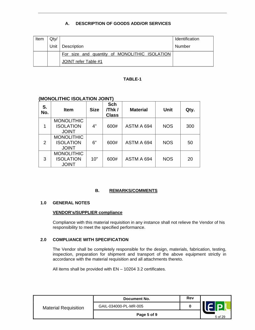
A. DESCRIPTION OF GOODS ADD/OR SERVICES
Item Qty/
Unit Description
Identification
Number
For size and quantity of MONOLITHIC ISOLATION
JOINT refer Table #1
TABLE-1
(MONOLITHIC ISOLATION JOINT)
S. No.
Item Size Sch
/Thk / Class
Material Unit Qty.
1 MONOLITHIC ISOLATION
JOINT 4” 600# ASTM A 694 NOS 300
2 MONOLITHIC ISOLATION
JOINT 6” 600# ASTM A 694 NOS 50
3 MONOLITHIC ISOLATION
JOINT 10" 600# ASTM A 694 NOS 20
B. REMARKS/COMMENTS
1.0 GENERAL NOTES
VENDOR's/SUPPLIER compliance Compliance with this material requisition in any instance shall not relieve the Vendor of his responsibility to meet the specified performance.
2.0 COMPLIANCE WITH SPECIFICATION
The Vendor shall be completely responsible for the design, materials, fabrication, testing, inspection, preparation for shipment and transport of the above equipment strictly in accordance with the material requisition and all attachments thereto. All items shall be provided with EN – 10204 3.2 certificates.
5 of 29
Material Requisition
Document No. Rev
GAIL-034000-PL-MR-005 0
Page 6 of 9
3.0 VENDOR's/SUPPLIER SCOPE
Vendor scope of work is included the equipment with all internals and accessories shown on the data sheets, specifications and all unmentioned parts necessary for a satisfactory operation and testing except those which are indicated to be out of the Vendor's supply.
4.0 INSPECTION
Vendor shall appoint a TPIA anyone of the following for inspection purpose without any extra cost to the owner, as set out and specified in the codes and particular documents forming this MR. Vendor has to propose minimum 2 nos. of below listed agencies to be approved by owner/owner’s representative.
a) Lloyd Register of Industrial Services b) Technische Ulierwachungs Verein (TUV) - NORD c) Det Norske Veritas (DNV) – GL d) Bureau Veritas e) SGS f) American Bureau services g) APPLUS VELOSI h) Certification Engineers international Limited (CEIL)
In addition to the above, owner also reserves the right to inspect and witness any tests during manufacturing at their own or through authorized representative.
5.0 APPLICABLE DOCUMENTS
General prescriptions, requirements and information are listed in annex C of this Material Requisition.
6.0 VENDOR's documents
Vendor shall submit the documents as listed under point D of this material requisition. All documents shall be submitted in english language only.
7.0 DOCUMENTS NUMBERING AND FORMAT
Vendor shall strictly follow the document numbering procedure in their document as instructed by the owner.
6 of 29
Material Requisition
Document No. Rev
GAIL-034000-PL-MR-005 0
Page 7 of 9
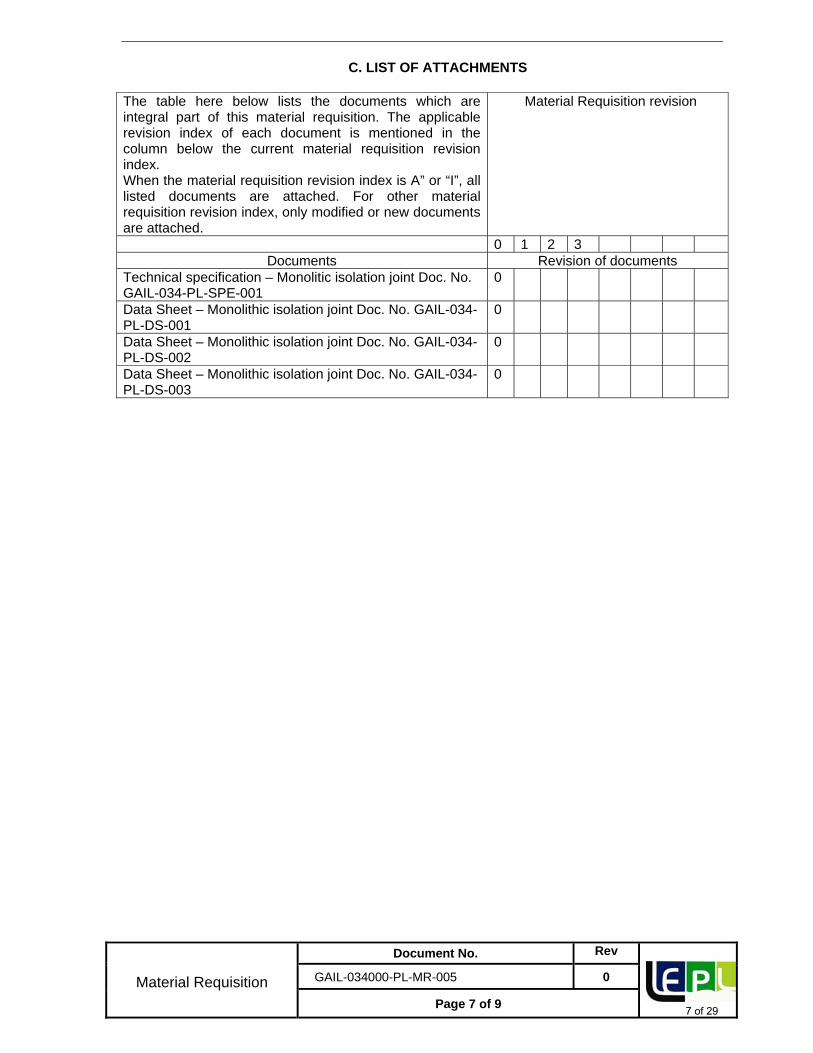
C. LIST OF ATTACHMENTS
The table here below lists the documents which are integral part of this material requisition. The applicable revision index of each document is mentioned in the column below the current material requisition revision index. When the material requisition revision index is A” or “I”, all listed documents are attached. For other material requisition revision index, only modified or new documents are attached.
Data Sheet – Monolithic isolation joint Doc. No. GAIL-034-PL-DS-001
0
Data Sheet – Monolithic isolation joint Doc. No. GAIL-034-PL-DS-002
0
Data Sheet – Monolithic isolation joint Doc. No. GAIL-034-PL-DS-003
0
7 of 29
Material Requisition
Document No. Rev
GAIL-034000-PL-MR-005 0
Page 8 of 9
D. DOCUMENTS & DATA REQUIREMENTS
The table hereunder specifies the quantities and the nature of the documents to be submitted by the Contractor / Vendor / Supplier to the Engineer. The documents required at the inquiry stage and to be included in the bid are listed under column A. The documents required after award of the Agreement and subject to the written approval of the Engineer are listed under column B. The final and certified documents are listed under column C. Any document, even when preliminary, shall be binding and therefore duly identified and signed by the Contractor/Vendor/Supplier. It shall bear the Engineer’s project reference, the Material Requisition number and the identification number. The documents are fully part of the supply which shall be complete only if and when the documents complying fully with the material requisition requirements are received by the engineer.
Item Document and Data Document Index No.
A B C No. of copies
No. of copies
Required date
No. of copies
Required date
1 Completed data sheet for Monolithic insulation joint
CDS 3 6 2 weeks 6 2 weeks + with final tech. file
2 Drawing / data submittal list / schedule
DLS 3 6 2 weeks + monthly
6 2 weeks
3 Progress report PRT - 6 2 weeks + monthly
6 2 weeks
4 Outline drawing + material specification + unit weight + Bill of materials (on drawings)
OMS - 6 2 weeks 6 2 weeks + with final tech. file
5 Code compliance certificate
CCC - 6 2 weeks 6 2 weeks + with final tech. file
6 Welding procedure specification and records WPS/PQR
WPS - 6 2 weeks 6 2 weeks + with final tech. file
7 QA/QC program* QAP 3 6 2 weeks 6 2 weeks + with final tech. file
8 Inspection and test procedures
ITP 3 6 2 weeks 6 2 weeks + with final tech. file
9 List of fabrication and LOF - 6 2 weeks 6 2 weeks +
8 of 29
Material Requisition
Document No. Rev
GAIL-034000-PL-MR-005 0
Page 9 of 9
control operations (LOFC)
with final tech. file
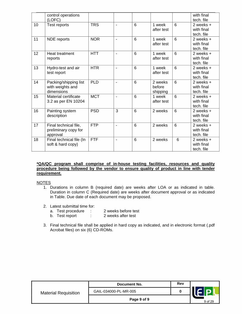
10 Test reports TRS - 6 1 week after test
6 2 weeks + with final tech. file
11 NDE reports NOR - 6 1 week after test
6 2 weeks + with final tech. file
12 Heat treatment reports
HTT - 6 1 week after test
6 2 weeks + with final tech. file
13 Hydro-test and air test report
HTR - 6 1 week after test
6 2 weeks + with final tech. file
14 Packing/shipping list with weights and dimensions
PLD - 6 2 weeks before shipping
6 2 weeks + with final tech. file
15 Material certificate 3.2 as per EN 10204
MCT - 6 1 week after test
6 2 weeks + with final tech. file
16 Painting system description
PSD 3 6 2 weeks 6 2 weeks + with final tech. file
17 Final technical file, preliminary copy for approval
FTP - 6 2 weeks 6 2 weeks + with final tech. file
18 Final technical file (In soft & hard copy)
FTF - 6 2 weeks 6 2 weeks + with final tech. file
*QA/QC program shall comprise of in-house testing facilities, resources and quality procedure being followed by the vendor to ensure quality of product in line with tender requirement.
NOTES
1. Durations in column B (required date) are weeks after LOA or as indicated in table. Duration in column C (Required date) are weeks after document approval or as indicated in Table. Due date of each document may be proposed.
2. Latest submittal time for: a. Test procedure : 2 weeks before test b. Test report : 2 weeks after test
3. Final technical file shall be applied in hard copy as indicated, and in electronic format (.pdf Acrobat files) on six (6) CD-ROMs.
9 of 29
ENGINEERING STANDARD
TECHNICAL SPECIFICATION FOR MONOLITHIC ISOLATION JOINT
GAIL‐034‐PL‐SPE‐001
0 30.01.19 Issued for Tender AP JR SB
Rev Date Purpose Prepared
By Checked
By Approved
By
10 of 29
Technical Specification For Monolithic Isolation Joint
3.0 MATERIALS .5 4.0 DESIGN AND CONSTRUCTION REQUIREMENTS .6 5.0 INSPECTION & TESTING .8 6.0 TEST CERTIFICATES 10 7.0 PAINTING, MARKING & SHIPMENT 10 8.0 SPARES AND ACCESSORIES 11 9.0 DOCUMENTATION 11
11 of 29
Technical Specification For Monolithic Isolation Joint
Doc No. Rev
GAIL-034-PL-SPE-001 0
Page 3 of 11
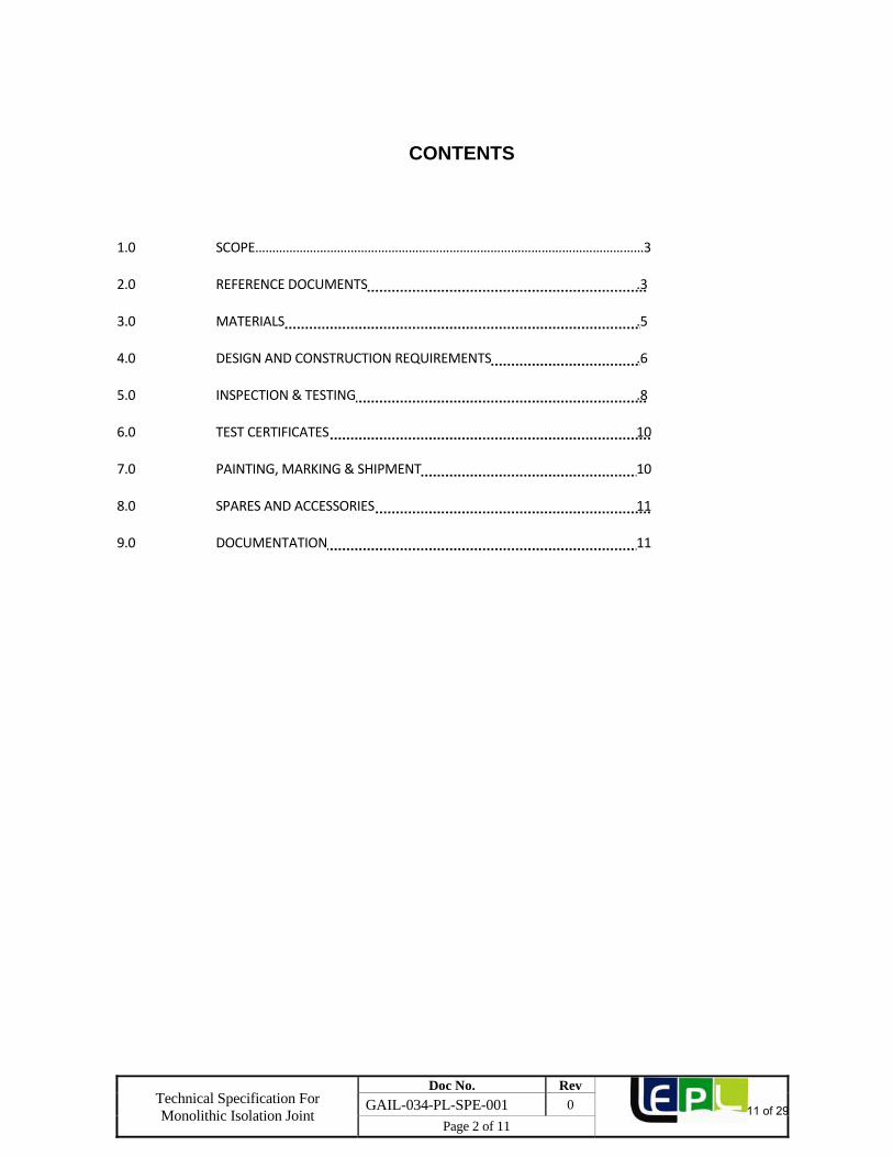
1.0 SCOPE
This specification defines the minimum technical requirements for the design, manufacture, testing and supply of carbon steel Insulating joints to be installed in onshore pipelines of Natural Gas services.
1.1 Abbreviations
The following definitions shall apply:
ASME : American Society of Mechanical Engineers.
ASNT : American Society for Non‐destructive Testing.
ASTM : American Society for Testing and Materials.
ISO : International Standards Organization.
NDE : Non‐destructive Examination.
MSS : Manufacturers Standardization Society.
NPS : Nominal Pipe Size.
UNS : Unified Numbering System.
1.2 Compliance
Compliance by the manufacturer with this specification shall not relieve him of his responsibilities to supply to meet the specified requirements and/or local codes governing health and safety.
The MANUFACTURER shall notify the purchaser / PMC / Owner in writing, of any proposed deviation from this Specification. The purchaser / PMC / Owner decision in respect of concession requests will be final. The MANUFACTURER shall continually verify the quality and fitness for purpose of the Monolithic Isolation Joint, and shall propose appropriate actions/measures if any aspects of manufacture are found to be unsatisfactory.
1.3 Quality Conformance
The MANUFACTURER shall demonstrate to the satisfaction of the purchaser / PMC / Owner that his activities within the scope of this document are in accordance with the relevant section of BS EN ISO 9001. The MANUFACTURER shall submit to the purchaser / PMC / Owner for review and approval, a Quality Plan and procedural specifications prior to commencement of work. The Quality Plan shall define all sub Manufacturer’s involvement in the work. The review in this Specification shall only indicate a general requirement and shall not relieve the MANUFACTURER of his obligations to comply with the requirements
1.4 Safety
Safety is paramount. All work shall be performed in accordance with the safety requirements listed in the contract documentation.
2.0 REFERENCE DOCUMENTS 2.1 Reference has been made in this specification to the latest edition of, the following Codes,
Standards and Specifications.
12 of 29
Technical Specification For Monolithic Isolation Joint
Doc No. Rev
GAIL-034-PL-SPE-001 0
Page 4 of 11
API 1104 : Specification for welding pipelines and related facilities.
ASME B 31.3 : Process piping. API 5L : Specification for Line Pipe
ASME B 31.8 : Gas Transmission and Distribution piping systems.
ASME Section VIII : Boiler & pressure Vessel Code. BPVC Section V : Non-Destructive Examination.
BPVC Section IX : Welding and Brazing qualifications ASME B16.9 : Factory made Wrought Butt Weld Fittings. ASTM A 370 : Standard Test Methods and Definitions for Mechanical Testing
of steel Products. ASTM B 733 : Auto catalytic Nickel Phosphorous coating on metals. ASME B16.34 : Valves – Flanged, Threaded and welding end
ANSI B 16.25 : Butt Welding Ends
ASTM A694 : Standard Specification for Carbon and Alloy Steel Forgings for
Pipe Flanges, Fittings, Valves, and Parts for High‐Pressure
Transmission Service
ASTM D2000 : Classification system for Rubber Products in Automotive.
ASTM D709 : Specification for Laminated Thermosetting Materials MSS-SP-75 : Specification for High Test Wrought Welding Fittings BS-EN-I0204 : Metallic Products - Types of Inspection Documents
ISO 2808 : Paints and Varnishes Determination of Film thickness
ISO 8501-1 : Preparation of Steel Substrates before Application of Paints and
Related Products - Visual Assessment of Surface Cleanliness.
PNGRB : Petroleum & Natural Gas Regulatory Board
EN 1024 : Metallic Materials‐Types of inspection documents.
NACE RP 286 : The electrical isolation of catholically protected pipelines. ISO 13623 : Petroleum & Natural Gas industry –Pipeline transportation
system. ISO 14313 : Petroleum & Natural Gas Industry, Pipeline transportation
system –pipeline valves. SSPC‐VIS‐I : Steel structures painting council‐Visual standard
13 of 29
Technical Specification For Monolithic Isolation Joint
Doc No. Rev
GAIL-034-PL-SPE-001 0
Page 5 of 11
SP‐10 : Surface Preparation. MSS‐SP‐25 : Standard marking systems for valves, Fittings, Flanges and
union. MSS‐SP‐75 : Specification for High Test Wrought welding fittings.
MSS‐SP‐53 : Quality standard for steel casting and forging for valves, flanges, fittings and other piping components –Magnetic particle Examination method.
OIL INDUSTRY SAFETY DIRECTORATE (OISD STANDARDS)
OISD 106 : Process design and operating philosophies on pressure relief and disposal system
OISD 113 : Classification of Area for electrical installation at Hydrocarbon
and handling facilities OISD 115 : Guidelines on Fire Fighting, Equipment and Appliance in
Petroleum Industry
OISD 163 : Process control room safety OISD 226 : Natural Gas Transmission pipelines and city gas distribution
networks. OISD 118 : Layouts for Oil & Gas Installation
OISD 141 : Design and Construction Requirements for Cross Country Hydrocarbon Pipelines.
MISCELLANEOUS
NEC : National Electric Code. ISO 2409 : Paints and Varnishes - Cross-Cut test.
In case of conflict between various requirements of this specification and reference standardsmentioned above, more stringent requirement shall apply unless otherwise agreed by Purchaser.
3.0 MATERIALS 3.1 Material for the pressure containing parts of the isolation joints shall be as indicated in the
monolithic isolation joint data sheets. Material for pups shall be equivalent or superior to the material of connecting pipeline, which is indicated in the data sheets. Pup piece material shall be such as to limit the thickness of pup piece to be welded with pipeline. Other part shall be as per Manufacturer's standard suitable for the service condition indicated in Isolation Joint Data Sheets and shall be subject to approval by purchaser / Purchaser’s representative.
All process wetted parts, metallic and non‐metallic shall be suitable for the commissioning fluids
and service specified by the company. Manufacturer shall confirm that all wetted parts are suitable for treated water/sea water environment, which may be used during field testing.
3.2 Isolation joints which are subjected to field welding by purchaser shall have carbon equivalent (CE)
not exceeding 0.43 based on check analysis for each heat of steel calculated according to the following formula:
CE = C + Mn/6 + (Cr+Mo+V)/5 + (Ni +Cu)/15
14 of 29
Technical Specification For Monolithic Isolation Joint
Doc No. Rev
GAIL-034-PL-SPE-001 0
Page 6 of 11
3.3 Charpy V‐notch test shall be conducted on each heat of base material, weld metal and heat
affected zone of all pressure containing parts such as body, welding ends in accordance with the impact test provisions of ASTM A 370 at a temperature of ‐20 °C. The charpy impact test specimens shall be taken in the direction of principal grain flow and notched perpendicular to the original surface of the plate of forging. Average impact energy value of three full sized specimens shall be 35 joules. Minimum impact energy value of individual specimen shall be 28 joules. No specimen shall exhibit less than 80% shear area.
3.4 Carbon steel used for the manufacture shall be fully killed. 3.5 Hardness test shall be carried out as per ASTM A370 for each heat of steel used. The maximum
hardness of base metal, weld metal and heat affected zone of all pressure parts shall be 248 HV10, unless specified otherwise.
4.0 DESIGN & CONSTRUCTION REQUIREMENTS 4.1 Mechanical 4.1.1 Isolation joints shall be of integral type fabricated by welding and with suitable pups on either side.
A corrosion allowance as indicated in data sheet shall be considered in design. Bolted and threaded joints are not acceptable.
4.1.2 All materials used for the manufacture of the Isolation joint shall be in accordance with clause 4.0
of this Specification. 41.3 Isolation joints shall be designed using the design principles of ASME Section‐VIII Div. 1. 4.1.4 Isolation joint design and materials shall be capable of being vacuum tested to 5 millibar. 4.1.5 The reinforcement of inside weld seam, in case pups fabricated from LSAW pipes, shall be removed
for a distance of at least 50mm from each end to facilitate welding. 4.1.8 Isolation joints shall allow free passage of scraper/ instrumented pigs. The internal bore shall be
same as that of connecting pipe including its tolerances. 4.1.9 The Isolation joint shall be formed by sandwiching and locking in positions the Isolation material in
a bell and spigot type of joint. The joint shall be assembled in such a way that its various components are firmly locked in position and the completed joint is capable of withstanding stresses due to designed operating conditions and field hydrostatic testing.
4.1.10 Isolation joints shall be suitable for aboveground installations as indicated in the data sheets. 4.1.11 All welds shall be made by welders and welding procedures qualified in accordance with the
provisions ASME section IX. The procedure qualification shall include impact test and hardness test and shall meet the requirements of clause 3.3 & 3.5 of this specification.
4.1.12 Repair welding on parent metal is not allowed. Purchaser’s representative for each repair shall
carry out repair of welds only after specific approval. Welders shall carry out the repair welding and welding procedures duly qualified as per ASME section IX and records for each repair shall be maintained.
4.1.13 Calculations shall be provided to show that the designed joint can withstand torsional stress up to
10% of the SMYS of the pup piece material.
15 of 29
Technical Specification For Monolithic Isolation Joint
Doc No. Rev
GAIL-034-PL-SPE-001 0
Page 7 of 11
4.1.14. The Manufacturer shall submit the detailed sectional drawing of the longitudinal face of the joint. The cross sectional drawing shall show all parts, materials, dimensions surface finishes and tolerances.
4.1.15. The insulating joint material shall be resistant to creep. 4.1.16. The external fasteners shall be hot dip galvanized as per ASTM A 153. 4.1.17. The selected seal material shall be resistant to the chemicals and the operating temperature and
pressure of the pipe system. At least 90% of the gasket shall be in contact with bare metal surface. The sealing gasket shall be of sufficient thickness and shall be made out of one piece of material, no joints are permitted.
4.1.18. No stress inducing recess, protrusions or notches, are permitted in the internal surface of the supplied joint. Additional fillers are not permitted to fill these flaws.
4.1.19. The cavities inside the joint shall be filled with low viscosity dielectric material that solidifies on curing. Air pockets and impurities in the dielectric material shall not be accepted.
4.1.20.. The Manufacturer shall submit the detailed sectional drawing of the longitudinal face of the joint. The cross sectional drawing shall show all parts, materials, dimensions surface finishes and tolerances.
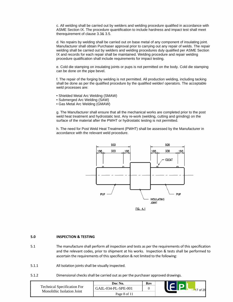
4.2 Electrical 4.2.1 The average dielectric strength of the Isolation joint shall be minimum 15 kilo Volts or more. 4.2.2 Two cleats shall be provided on the pups on either side of the Isolation joint for connecting 10 mm2
and 50 mm2 cables for measurement/ shorting purposes. Cleats shall be attached to the Isolation joint by welding.
4.3 NON METALLIC COMPONENTS
Minimum thickness requirement of insulating material shall comply with NACE RP 0286. Epoxy resin filler material used shall be CIBA Araldite CY-220 & Araldite HT-951 hardener or an approved equivalent.
Insulating rings and joint filler material shall be flame resistant and capable of safely withstanding the maximum operating temperature without distortion or loss of insulating properties. Non-metallic seal materials, if provided, shall be resistant to amine based corrosion inhibitors and explosive decompression. The spacing ring shall be of epoxy glass fiber reinforced laminate. It shall possess high insulating properties that would comply with ASTM D 709 Type TV, Group G.1.1 properties. The materials compressive properties shall be equal to or greater than 450 MPa. The epoxy glass fiber laminates material shall possess anti-aging properties. The spacing ring, sealing gasket and filling material shall be resistant to flames and diffusion of gases, absorption of moisture and shall be capable of maintaining their required compressive strength and insulating properties over the design life of the pipeline. Adhesive sealant or a low viscosity, cold curing thermosetting resin shall be used as filling material. Its compressive strength shall be equal to or greater than 150 MPa. Plastic material shall be compatible to the materials they are in contact with. The Manufacturer shall give the details of the plastic used and its mechanical, chemical and temperature resistance properties.
4.4 WELDING
a. All welds except closing weld shall be butt welds. The closing weld shall be full penetration girth weld in accordance with ASME BPVC Section VIII, Division I. The weld design shall conform to the ASME acceptable standards. Fillet welds if required, shall have minimum two passes. b. Welding end of the pipe pups to be welded to the insulating joint shall be prepared in accordance with ASME B31.4/ B31.8, as applicable. All butt weld ends shall be checked for surface defectsusing dye penetrate prior to welding.
16 of 29
Technical Specification For Monolithic Isolation Joint
Doc No. Rev
GAIL-034-PL-SPE-001 0
Page 8 of 11
c. All welding shall be carried out by welders and welding procedure qualified in accordance with ASME Section IX. The procedure quantification to include hardness and impact test shall meet therequirement of clause 3.3& 3.5. d. No repairs by welding shall be carried out on base metal of any component of insulating joint. Manufacturer shall obtain Purchaser approval prior to carrying out any repair of welds. The repair welding shall be carried out by welders and welding procedures duly qualified per ASME Section IX and records for each repair shall be maintained. Welding procedure and repair welding procedure qualification shall include requirements for impact testing.
e. Cold die stamping on insulating joints or pups is not permitted on the body. Cold die stamping can be done on the pipe bevel.
f. The repair of the forging by welding is not permitted. All production welding, including tacking shall be done as per the qualified procedure by the qualified welder/ operators. The acceptable weld processes are: • Shielded Metal Arc Welding (SMAW) • Submerged Arc Welding (SAW) • Gas Metal Arc Welding (GMAW)
g. The Manufacturer shall ensure that all the mechanical works are completed prior to the post weld heat treatment and hydrostatic test. Any re-work (welding, cutting and grinding) on the surface of the material after the PWHT or hydrostatic testing is not permitted. h. The need for Post Weld Heat Treatment (PWHT) shall be assessed by the Manufacturer in accordance with the relevant weld procedure.
5.0 INSPECTION & TESTING 5.1 The manufacture shall perform all inspection and tests as per the requirements of this specification
and the relevant codes, prior to shipment at his works. Inspection & tests shall be performed to ascertain the requirements of this specification & not limited to the following:
5.1.1 All Isolation joints shall be visually inspected. 5.1.2 Dimensional checks shall be carried out as per the purchaser approved drawings.
17 of 29
Technical Specification For Monolithic Isolation Joint
Doc No. Rev
GAIL-034-PL-SPE-001 0
Page 9 of 11
5.1.3 Chemical composition and mechanical properties including hardness shall be checked as per
relevant material standards and this specification, for each heat of steel used. 5.1.4 Non‐destructive inspection of Isolation joints shall be carried out as given below:
a) 100% radiography shall be carried out on all butt & repair welds of pressure containing parts. Acceptance limits shall be as per API 1104.
Welds, which in purchaser's representative opinion cannot be inspected by radiographic
methods, shall be checked by ultrasonic or magnetic particle methods. Acceptance criteria shall be as per ASME Section VIII Appendix‐12 and Appendix‐6 respectively.
b) All finished weld ends shall be 100% ultrasonically tested for lamination type defects for a
distance of 50mm from the ends. Any lamination is not acceptable.
c) All forgings shall be wet magnetic particle inspected on 100% of forged surfaces. Method and
acceptance shall comply with MSS‐SP‐53 and ASME Sec VIII DIV 2.
d) All fillet weld of thickness < 6mm shall be examined 100% by magnetic particle inspection and
6mm shall be examined 100% by UT. Acceptance criteria for MPI & UT shall be as per ASME Sec.VIII Appendix‐6 & Appendix‐12 respectively.
5.1.5 Isolation joint shall be hydrostatically tested to a pressure as indicated in data sheet. The test
duration shall be of 60 minutes. 5.1.6 Upon successful completion of hydrostatic testing, the joint shall be subjected to a minimum of 40
Pressure cycles from 10 bars to 85% of the hydrostatic test pressure. After cycling, the pressure shallbe raised to the hydrostatic test pressure and maintained for at least 30 minutes.
5.1.6 After the hydrostatic test Isolation joints shall be tested with air at 7 bar (g) for 10 minutes.The tightness shall be checked by immersion or with a frothing agent. No leakage shall be acceptable.
5.1.7 Dielectric Test
a) Insulation resistance of each Isolation joint shall be at least 50 mega‐ohms when checked with1000 V DC.
b) Isolation joint before and after the hydrostatic test, shall be tested for dielectric integrity for
one minute at 5000 V A.C., 50 cycles and the leakage current before and after hydrostatic test shall be equal. Testing time voltage and leakage shall be recorded and certified. No repair shall be permitted to the Isolation joints failed in the above mentioned tests.
5.2 Purchaser reserves the right to perform stage wise inspection and witness test as indicated in Para
5.1 at Manufacturer's works prior to shipment. Manufacturer shall give reasonable notice of time and shall provide without charge reasonable access and facilities required for inspection to the purchaser's Representative.
Inspection and tests performed/witnessed by the Purchaser's Representative shall in no way
relieve the Manufacturer's obligation to perform the required inspection and test. 6.0 TEST CERTIFICATES
18 of 29
Technical Specification For Monolithic Isolation Joint
Doc No. Rev
GAIL-034-PL-SPE-001 0
Page 10 of 11
6.1 Manufacturer shall submit following certificates to Purchaser's Representative.
a) Test certificates relevant to the chemical analysis and mechanical properties including hardness of the materials used for construction of Isolation joint as per this specification and relevant standards.
b) Test reports on non‐destructive testing. c) Test certificates for hydrostatic and air tests. d) Test certificate for electrical resistance test.
e) Test report for dielectric strength test. 7.0 PAINTING, MARKING AND SHIPMENT 7.1 Isolation joint surface shall be thoroughly cleaned, freed from rust and grease and applied with
sufficient coats of corrosion resistant paint. Surface preparation shall be carried out by shot blasting to SP‐10 in accordance with "steel structures painting council ‐ Visual standard SSPC‐VIS‐l." External surfaces of Isolation joints shall be painted with three coats of suitable epoxy resin with a minimum dry film thickness of 320 microns and it shall be suitable for corrosive industrial environment.
Manufacturer shall indicate the type of corrosion resistant paint used, in the drawings submitted
for approval. 7.2 Isolation joints shall be marked with indelible paint with the following data:‐ a. Manufacturer's name b. Suitable for‐ inch nominal diameter pipeline c. End thickness in mm d. Material
e. Design Pressure/ Hydrostatic Test Pressure f. ANSI Class Rating
g. Tag No.
h. Year of Manufacture
i. PO No.
7.3 Isolation joints shall be suitably protected to avoid any damage during transit. Metallic bevel
protectors shall be provided to weld ends. 7.4 Only those Isolation joints, which have been inspected and certified by Purchaser, shall be shipped.
19 of 29
Technical Specification For Monolithic Isolation Joint
Doc No. Rev
GAIL-034-PL-SPE-001 0
Page 11 of 11
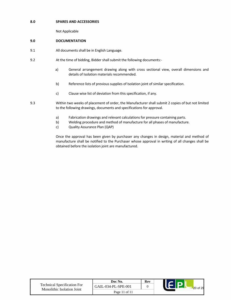
8.0 SPARES AND ACCESSORIES Not Applicable 9.0 DOCUMENTATION 9.1 All documents shall be in English Language. 9.2 At the time of bidding, Bidder shall submit the following documents:‐ a) General arrangement drawing along with cross sectional view, overall dimensions and
details of Isolation materials recommended. b) Reference lists of previous supplies of Isolation joint of similar specification. c) Clause wise list of deviation from this specification, if any.
9.3 Within two weeks of placement of order, the Manufacturer shall submit 2 copies of but not limited
to the following drawings, documents and specifications for approval. a) Fabrication drawings and relevant calculations for pressure containing parts. b) Welding procedure and method of manufacture for all phases of manufacture. c) Quality Assurance Plan (QAP) Once the approval has been given by purchaser any changes in design, material and method of
manufacture shall be notified to the Purchaser whose approval in writing of all changes shall be obtained before the isolation joint are manufactured.
20 of 29
Lyons Engineering Pvt. Ltd.
DATA SHEET FOR INSULATING JOINT
Doc No. GAIL-034-PL-DS-001 Page 1 of 3
0 30.01.19 Issued for Tender
AP TR SB
Rev. Date Purpose Prepared By: Checked By: Approved By:
Tag No. : As per PO
Owner Specification No. : GAIL-034-PL-SPE-001
Design Std : ASME BPVC SEC VIII DIV 1, ASME B31.8
Size : 4”
ANSI Rating : 600#
End Connection : Butt Weld Ends ASME B16.25/ ASME B 31.8
VALVE DESIGN CONDITION
Corrosion Allowance : 0.5 mm Temperature in °C
: (‐)20 to (+)65
Service : Natural Gas (Non‐sour)
Installation : A/G
Design Factor : 0.5 Connecting Pipe : 4 Inch (API 5L X42), 6.4 mm WT
VALVE MATERIAL SPECIFICATION (Equivalent or superior)
Description Material Specified Material Offered**
Body MSS SP‐75, WPHY Gr. 42/ ASTM A 694 Gr. F 42.
Pup Piece Seamless API 5L X‐42 6.4 mm
Insulation As per specification
**‐ To be filled by vendor
21 of 29
Lyons Engineering Pvt. Ltd.
DATA SHEET FOR INSULATING JOINT
Doc No. GAIL-034-PL-DS-001 Page 2 of 3
0 30.01.19 Issued for Tender
AP TR SB
Rev. Date Purpose Prepared By: Checked By: Approved By:
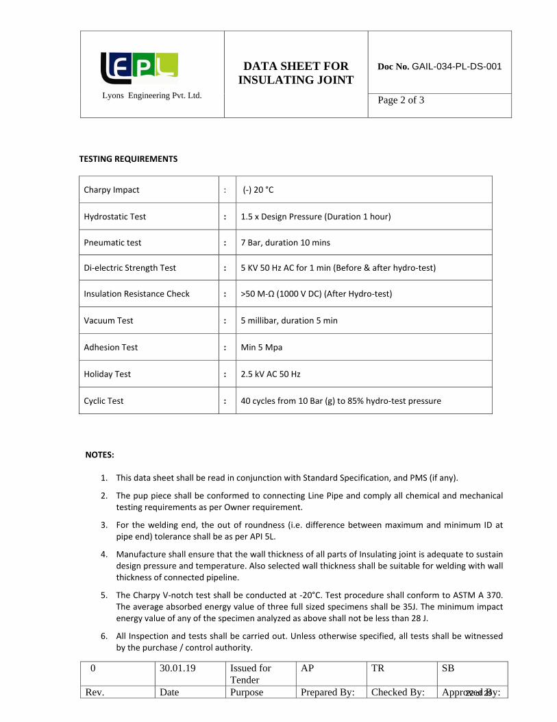
TESTING REQUIREMENTS
Charpy Impact : (‐) 20 °C
Hydrostatic Test : 1.5 x Design Pressure (Duration 1 hour)
Pneumatic test : 7 Bar, duration 10 mins
Di‐electric Strength Test : 5 KV 50 Hz AC for 1 min (Before & after hydro‐test)
Cyclic Test : 40 cycles from 10 Bar (g) to 85% hydro‐test pressure
NOTES:
1. This data sheet shall be read in conjunction with Standard Specification, and PMS (if any).
2. The pup piece shall be conformed to connecting Line Pipe and comply all chemical and mechanical testing requirements as per Owner requirement.
3. For the welding end, the out of roundness (i.e. difference between maximum and minimum ID at pipe end) tolerance shall be as per API 5L.
4. Manufacture shall ensure that the wall thickness of all parts of Insulating joint is adequate to sustain design pressure and temperature. Also selected wall thickness shall be suitable for welding with wall thickness of connected pipeline.
5. The Charpy V‐notch test shall be conducted at ‐20°C. Test procedure shall conform to ASTM A 370. The average absorbed energy value of three full sized specimens shall be 35J. The minimum impact energy value of any of the specimen analyzed as above shall not be less than 28 J.
6. All Inspection and tests shall be carried out. Unless otherwise specified, all tests shall be witnessed by the purchase / control authority.
22 of 29
Lyons Engineering Pvt. Ltd.
DATA SHEET FOR INSULATING JOINT
Doc No. GAIL-034-PL-DS-001 Page 3 of 3
0 30.01.19 Issued for Tender
AP TR SB
Rev. Date Purpose Prepared By: Checked By: Approved By:
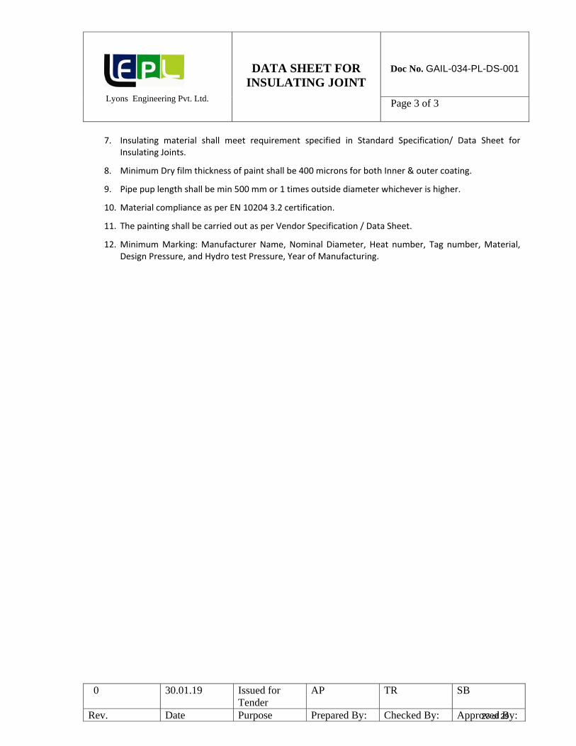
7. Insulating material shall meet requirement specified in Standard Specification/ Data Sheet for Insulating Joints.
8. Minimum Dry film thickness of paint shall be 400 microns for both Inner & outer coating.
9. Pipe pup length shall be min 500 mm or 1 times outside diameter whichever is higher.
10. Material compliance as per EN 10204 3.2 certification.
11. The painting shall be carried out as per Vendor Specification / Data Sheet.
12. Minimum Marking: Manufacturer Name, Nominal Diameter, Heat number, Tag number, Material, Design Pressure, and Hydro test Pressure, Year of Manufacturing.
23 of 29
Lyons Engineering Pvt. Ltd.
DATA SHEET FOR INSULATING JOINT
Doc No. GAIL-034-PL-DS-002 Page 1 of 3
0 30.01.19 Issued for Tender
AP TR SB
Rev. Date Purpose Prepared By: Checked By: Approved By:
Tag No. : As per PO
Owner Specification No. : GAIL-034-PL-SPE-001
Design Std : ASME BPVC SEC VIII DIV 1, ASME B31.8
Size : 6”
ANSI Rating : 600#
End Connection : Butt Weld Ends ASME B16.25/ ASME B 31.8
VALVE DESIGN CONDITION
Corrosion Allowance : 0.5 mm Temperature in °C
: (‐)20 to (+)65
Service : Natural Gas (Non‐sour)
Installation : A/G
Design Factor : 0.5 Connecting Pipe : 6 Inch (API 5L X52), 6.4 mm WT
VALVE MATERIAL SPECIFICATION (Equivalent or superior)
Description Material Specified Material Offered**
Body MSS SP‐75, WPHY Gr. 52/ ASTM A 694 Gr. F 52.
Pup Piece Seamless API 5L X‐52 6.4 mm
Insulation As per specification
**‐ To be filled by vendor
24 of 29
Lyons Engineering Pvt. Ltd.
DATA SHEET FOR INSULATING JOINT
Doc No. GAIL-034-PL-DS-002 Page 2 of 3
0 30.01.19 Issued for Tender
AP TR SB
Rev. Date Purpose Prepared By: Checked By: Approved By:
TESTING REQUIREMENTS
Charpy Impact : (‐) 20 °C
Hydrostatic Test : 1.5 x Design Pressure (Duration 1 hour)
Pneumatic test : 7 Bar, duration 10 mins
Di‐electric Strength Test : 5 KV 50 Hz AC for 1 min (Before & after hydro‐test)
Cyclic Test : 40 cycles from 10 Bar (g) to 85% hydro‐test pressure
NOTES:
1. This data sheet shall be read in conjunction with Standard Specification and PMS (if any).
2. The pup piece shall be conformed to connecting Line Pipe and comply all chemical and mechanical testing requirements as per Owner requirement.
3. For the welding end, the out of roundness (i.e. difference between maximum and minimum ID at pipe end) tolerance shall be as per API 5L.
4. Manufacture shall ensure that the wall thickness of all parts of Insulating joint is adequate to sustain design pressure and temperature. Also selected wall thickness shall be suitable for welding with wall thickness of connected pipeline.
5. The Charpy V‐notch test shall be conducted at ‐20°C. Test procedure shall conform to ASTM A 370. The average absorbed energy value of three full sized specimens shall be 35J. The minimum impact energy value of any of the specimen analyzed as above shall not be less than 28 J.
6. All Inspection and tests shall be carried out. Unless otherwise specified, all tests shall be witnessed by the purchase / control authority.
25 of 29
Lyons Engineering Pvt. Ltd.
DATA SHEET FOR INSULATING JOINT
Doc No. GAIL-034-PL-DS-002 Page 3 of 3
0 30.01.19 Issued for Tender
AP TR SB
Rev. Date Purpose Prepared By: Checked By: Approved By:
7. Insulating material shall meet requirement specified in Standard Specification/ Data Sheet for Insulating Joints.
8. Minimum Dry film thickness of paint shall be 400 microns for both Inner & outer coating.
9. Pipe pup length shall be min 500 mm or 1 times outside diameter whichever is higher.
10. Material compliance as per EN 10204 3.2 certification.
11. The painting shall be carried out as per Vendor Specification / Data Sheet.
12. Minimum Marking: Manufacturer Name, Nominal Diameter, Heat number, Tag number, Material, Design Pressure, and Hydro test Pressure, Year of Manufacturing.
26 of 29
Lyons Engineering Pvt. Ltd.
DATA SHEET FOR INSULATING JOINT
Doc No. GAIL-034-PL-DS-003 Page 1 of 3
0 30.01.19 Issed for Tender
AP TR SB
Rev. Date Purpose Prepared By: Checked By: Approved By:
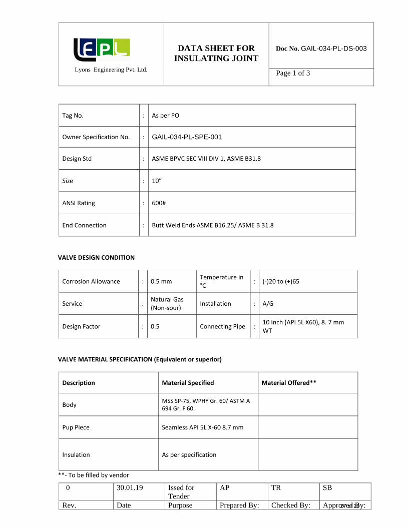
Tag No. : As per PO
Owner Specification No. : GAIL-034-PL-SPE-001
Design Std : ASME BPVC SEC VIII DIV 1, ASME B31.8
Size : 10”
ANSI Rating : 600#
End Connection : Butt Weld Ends ASME B16.25/ ASME B 31.8
VALVE DESIGN CONDITION
Corrosion Allowance : 0.5 mm Temperature in °C
: (‐)20 to (+)65
Service : Natural Gas (Non‐sour)
Installation : A/G
Design Factor : 0.5 Connecting Pipe : 10 Inch (API 5L X60), 8. 7 mm WT
VALVE MATERIAL SPECIFICATION (Equivalent or superior)
Description Material Specified Material Offered**
Body MSS SP‐75, WPHY Gr. 60/ ASTM A 694 Gr. F 60.
Pup Piece Seamless API 5L X‐60 8.7 mm
Insulation As per specification
**‐ To be filled by vendor
27 of 29
Lyons Engineering Pvt. Ltd.
DATA SHEET FOR INSULATING JOINT
Doc No. GAIL-034-PL-DS-003 Page 2 of 3
0 30.01.19 Issed for Tender
AP TR SB
Rev. Date Purpose Prepared By: Checked By: Approved By:
TESTING REQUIREMENTS
Charpy Impact : (‐) 20 °C
Hydrostatic Test : 1.5 x Design Pressure (Duration 1 hour)
Pneumatic test : 7 Bar, duration 10 mins
Di‐electric Strength Test : 5 KV 50 Hz AC for 1 min (Before & after hydro‐test)
Cyclic Test : 40 cycles from 10 Bar (g) to 85% hydro‐test pressure
NOTES:
1. This data sheet shall be read in conjunction with Standard Specification and PMS (if any).
2. The pup piece shall be conformed to connecting Line Pipe and comply all chemical and mechanical testing requirements as per Owner requirement.
3. For the welding end, the out of roundness (i.e. difference between maximum and minimum ID at pipe end) tolerance shall be as per API 5L.
4. Manufacture shall ensure that the wall thickness of all parts of Insulating joint is adequate to sustain design pressure and temperature. Also selected wall thickness shall be suitable for welding with wall thickness of connected pipeline.
5. The Charpy V‐notch test shall be conducted at ‐20°C. Test procedure shall conform to ASTM A 370. The average absorbed energy value of three full sized specimens shall be 35J. The minimum impact energy value of any of the specimen analyzed as above shall not be less than 28 J.
6. All Inspection and tests shall be carried out. Unless otherwise specified, all tests shall be witnessed by the purchase / control authority.
28 of 29
Lyons Engineering Pvt. Ltd.
DATA SHEET FOR INSULATING JOINT
Doc No. GAIL-034-PL-DS-003 Page 3 of 3
0 30.01.19 Issed for Tender
AP TR SB
Rev. Date Purpose Prepared By: Checked By: Approved By:
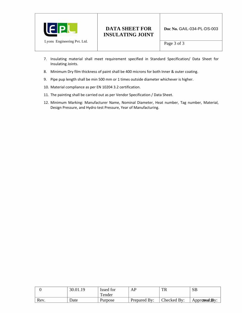
7. Insulating material shall meet requirement specified in Standard Specification/ Data Sheet for Insulating Joints.
8. Minimum Dry film thickness of paint shall be 400 microns for both Inner & outer coating.
9. Pipe pup length shall be min 500 mm or 1 times outside diameter whichever is higher.
10. Material compliance as per EN 10204 3.2 certification.
11. The painting shall be carried out as per Vendor Specification / Data Sheet.
12. Minimum Marking: Manufacturer Name, Nominal Diameter, Heat number, Tag number, Material, Design Pressure, and Hydro test Pressure, Year of Manufacturing.