“Galileo Galilei” (GG): space test of the weak Equivalence Principle to 10 -17 and laboratory demonstrations A. M. Nobili, 1, 2 M. Shao, 3 R. Pegna, 2 G. Zavattini, 4, 5 S. G. Turyshev, 3 D. M. Lucchesi, 6, 2 A. De Michele, 1 S. Doravari, 7 G. L. Comandi, 2 T. R. Saravanan, 1 F. Palmonari, 8, 9 G. Catastini, 10 and A. Anselmi 10 1 Dept. of Physics “E. Fermi”, University of Pisa, Largo Bruno Pontecorvo 3, 56127 Pisa, Italy 2 INFN-Istituto Nazionale di Fisica Nucleare, Sezione di Pisa, Largo Bruno Pontecorvo 3, 56127 Pisa, Italy 3 Jet Propulsion Laboratory, California Inst. of Tech., 4800 Oak Grove Dr., Pasadena, CA 91109, USA 4 Dept. of Physics, University of Ferrara, Via Saragat 1, 44122 Ferrara, Italy 5 INFN-Istituto Nazionale di Fisica Nucleare, Sezione di Ferrara, Via Saragat 1, 44122 Ferrara, Italy 6 INAF-IAPS-Istituto di Astrofisica e Planetologia Spaziali, Via Fosso del Cavaliere 100, 00133 Roma, Italy 7 California Inst. of Tech., Pasadena, CA 91109 8 Dept. of Physics, University of Bologna, Viale Berti Pichat 6/2 40127 Bologna, Italy 9 INFN-Istituto Nazionale di Fisica Nucleare, Sezione di Bologna, Viale Berti Pichat 6/2 40127 Bologna, Italy 10 Thales Alenia Space Italia, Strada Antica di Collegno 253, 10146 Torino, Italy (Dated: 22 February 2012; Revised 27 May 2012; Final revision July 2012) The small satellite “Galileo Galilei” (GG) will test the Universality of Free Fall, hence the Weak Equivalence Principle which is the founding pillar of General Relativity to 1 part in 10 17 . It will use proof masses whose atoms differ substantially from one another in their mass energy-content, so as to maximize the chance of violation. GG will improve by 4 orders of magnitude the current best “E¨ ot-Wash” tests based on slowly rotating torsion balances, which have been able to reach their thermal noise level. In GG the expected violation signal is a relative displacement between the proof masses of ’ 0.6 pm caused by a differential acceleration a GG ’ 8 · 10 -17 ms -2 pointing to the center of mass of the Earth as the satellite orbits around it at νGG ’ 1.7 · 10 -4 Hz. GG will fly an innovative acceleration sensor based on rapidly rotating macroscopic test masses weakly coupled in 2D which up-converts the signal to νspin ’ 1Hz, a value well above the frequency of natural oscillations of the masses relative to each other ν d =1/T d ’ 1/(540 s). The sensor is unique in that it ensures high rotation frequency, low thermal noise and no attenuation of the signal strength[1]. A readout based on a very low noise laser interferometry gauge developed at JPL (’ 1 pm/ √ Hz @ 1 Hz demonstrated) allows the short integration time to be fully exploited. A full scale sensor with the same degrees of freedom and the same dynamical features as the one to fly in GG has been set-up on ground (GGG). The proof masses of GGG are affected by acceleration and tilt noise acting on the rotating shaft because of ball bearings and terrain microseismicity (both absent in space). Overall, by means of appropriate 2D flexure joints, these noise sources have been reduced by a factor almost 10 5 down to a differential acceleration between the proof masses of ’ 7 · 10 -11 m/s 2 (@ 1.7 · 10 -4 Hz up-converted by rotation to ’ 0.2 Hz). The corresponding noise in the relative displacements of the proof masses, read by co-rotating capacitance bridges, is ’ 180 pm, which is 300 times larger than the target in space. GGG error budget shows that it can reach a differential acceleration sensitivity a GGGgoal ’ 8 · 10 -16 m/s 2 , not limited by thermal noise. This value is only a factor 10 larger than what GG must reach in space to meet its target, and slightly smaller than the acceleration noise of the torsion balance. It can be achieved partly by means of weaker joints and an optimized mechanical design –so as to improve the attenuation factor– and partly by replacing the current ball bearings with much less noisy air bearings (also used in torsion balance tests) so as to reduce input noise. A laser gauge readout with noise level r laser-ro ’ 30 pm/ √ Hz @ 0.2 ÷ 3 Hz will be implemented. I. WHY TESTING THE WEAK EQUIVALENCE PRINCIPLE IN SPACE? General Relativity (GR) is the best theory of gravity to-date. It governs physics at the macroscopic and cosmic scales and it has been highly successful. However, all attempts at merging gravity with the other forces of nature have failed and most of the mass of the universe is unexplained. GR is based on the hypothesis that the gravitational force is composition independent: in a gravitational field all bodies fall with the same acceleration regardless of their mass and composition. This property is unique to gravity. It is referred to as the Universality of Free Fall, and it is the direct consequence of the equivalence between inertial and gravitational mass assumed by Newton in 1687 in the opening
Transcript
“Galileo Galilei” (GG): space test of the weak Equivalence Principle to10−17 and laboratory demonstrations
A. M. Nobili,1, 2 M. Shao,3 R. Pegna,2 G. Zavattini,4, 5 S. G. Turyshev,3
D. M. Lucchesi,6, 2 A. De Michele,1 S. Doravari,7 G. L. Comandi,2
T. R. Saravanan,1 F. Palmonari,8, 9 G. Catastini,10 and A. Anselmi10
1 Dept. of Physics “E. Fermi”, University of Pisa,Largo Bruno Pontecorvo 3, 56127 Pisa, Italy
2INFN-Istituto Nazionale di Fisica Nucleare, Sezione di Pisa,Largo Bruno Pontecorvo 3, 56127 Pisa, Italy
3Jet Propulsion Laboratory, California Inst. of Tech.,4800 Oak Grove Dr., Pasadena, CA 91109, USA
4 Dept. of Physics, University of Ferrara, Via Saragat 1, 44122 Ferrara, Italy5INFN-Istituto Nazionale di Fisica Nucleare,
Sezione di Ferrara, Via Saragat 1, 44122 Ferrara, Italy6 INAF-IAPS-Istituto di Astrofisica e Planetologia Spaziali,
Via Fosso del Cavaliere 100, 00133 Roma, Italy7 California Inst. of Tech., Pasadena, CA 91109
8 Dept. of Physics, University of Bologna,Viale Berti Pichat 6/2 40127 Bologna, Italy
9INFN-Istituto Nazionale di Fisica Nucleare, Sezione di Bologna,Viale Berti Pichat 6/2 40127 Bologna, Italy
10Thales Alenia Space Italia, Strada Antica di Collegno 253, 10146 Torino, Italy(Dated: 22 February 2012; Revised 27 May 2012; Final revision July 2012)
The small satellite “Galileo Galilei” (GG) will test the Universality of Free Fall, hence the WeakEquivalence Principle which is the founding pillar of General Relativity to 1 part in 1017. It willuse proof masses whose atoms differ substantially from one another in their mass energy-content,so as to maximize the chance of violation. GG will improve by 4 orders of magnitude the currentbest “Eot-Wash” tests based on slowly rotating torsion balances, which have been able to reachtheir thermal noise level. In GG the expected violation signal is a relative displacement betweenthe proof masses of ' 0.6 pm caused by a differential acceleration aGG ' 8 · 10−17 ms−2 pointing tothe center of mass of the Earth as the satellite orbits around it at νGG ' 1.7 · 10−4 Hz. GG will flyan innovative acceleration sensor based on rapidly rotating macroscopic test masses weakly coupledin 2D which up-converts the signal to νspin ' 1 Hz, a value well above the frequency of naturaloscillations of the masses relative to each other νd = 1/Td ' 1/(540 s). The sensor is unique in thatit ensures high rotation frequency, low thermal noise and no attenuation of the signal strength [1].
A readout based on a very low noise laser interferometry gauge developed at JPL (' 1 pm/√
Hz@ 1 Hz demonstrated) allows the short integration time to be fully exploited. A full scale sensorwith the same degrees of freedom and the same dynamical features as the one to fly in GG hasbeen set-up on ground (GGG). The proof masses of GGG are affected by acceleration and tilt noiseacting on the rotating shaft because of ball bearings and terrain microseismicity (both absent inspace). Overall, by means of appropriate 2D flexure joints, these noise sources have been reduced bya factor almost 105 down to a differential acceleration between the proof masses of ' 7 · 10−11 m/s2
(@ 1.7 · 10−4 Hz up-converted by rotation to ' 0.2 Hz). The corresponding noise in the relativedisplacements of the proof masses, read by co-rotating capacitance bridges, is ' 180 pm, which is300 times larger than the target in space. GGG error budget shows that it can reach a differentialacceleration sensitivity aGGGgoal ' 8 ·10−16 m/s2, not limited by thermal noise. This value is only afactor 10 larger than what GG must reach in space to meet its target, and slightly smaller than theacceleration noise of the torsion balance. It can be achieved partly by means of weaker joints andan optimized mechanical design –so as to improve the attenuation factor– and partly by replacingthe current ball bearings with much less noisy air bearings (also used in torsion balance tests) so as
to reduce input noise. A laser gauge readout with noise level rlaser−ro ' 30 pm/√
Hz @ 0.2÷ 3 Hzwill be implemented.
I. WHY TESTING THE WEAK EQUIVALENCE PRINCIPLE IN SPACE?
General Relativity (GR) is the best theory of gravity to-date. It governs physics at the macroscopicand cosmic scales and it has been highly successful. However, all attempts at merging gravity withthe other forces of nature have failed and most of the mass of the universe is unexplained. GR isbased on the hypothesis that the gravitational force is composition independent: in a gravitationalfield all bodies fall with the same acceleration regardless of their mass and composition. This propertyis unique to gravity. It is referred to as the Universality of Free Fall, and it is the direct consequenceof the equivalence between inertial and gravitational mass assumed by Newton in 1687 in the opening
Anna
Typewritten Text
Anna
Typewritten Text
Anna
Typewritten Text
Anna
Typewritten Text
Anna
Typewritten Text
Classical and Quantum Gravity, Focus issue on the Weak Equivalence Principle, to appear
Anna
Typewritten Text
2
paragraph of the Principia. It is the basic assumption of the much more general equivalence principleformulated by Einstein in 1907 [2] which 8 years later led him to GR. This principle is known asthe Strong Equivalence Principle (see Dicke’s formulation [3] p. 4) or as Einstein Equivalence Princi-ple [4] while Newton’s equivalence of inertial and gravitational mass is now referred to as the WeakEquivalence Principle (WEP).
If the Universality of Free fall and the WEP are invalidated by experiments, so is the StrongEquivalence Principle. As a result, either GR should be amended or we are in the presence of a newforce of nature.
Tests of WEP are unique tests of GR. They address the assumed composition independence ofgravity which sets it aside from all other forces of nature; moreover, if properly designed, they are nullexperiments and therefore can reach very high sensitivity. For these reasons they are the most deeplyprobing tests in the search for new physics beyond General Relativity and the current impasse, andshould therefore be pushed to higher and higher sensitivity whenever the experimental possibility foran improvement arises.
Such improvements occurred several times in history. In 1600 Galileo suspended masses made ofdifferent material from wires rather than dropping them from a height (to avoid limitations due to theshort time of fall and the bodies release errors) and found that they fall with the same accelerationwith a fractional difference of ' 10−3 [5] [6]. In the early 1900 Eotvos coupled the proof masses byplacing them on a torsion balance whose high sensitivity and perfect rejection of common mode effectsallowed him to reach the amazing level of 10−8 [7] on which Einstein relied ([8] p. 114). In the fieldof the Earth the signal is DC and the torsion balance test lacks modulation. In order to overcomethis limitation without rotating the balance Dicke and Braginsky in the 1960s and 70s searched forviolation in the field of the Sun exploiting the diurnal rotation of the Earth in order to modulatethe signal. Although the signal from the Sun is slightly weaker than that from the Earth, signalmodulation allowed them to make a very substantial improvement reaching 10−11 [9] and 10−12 [10].In the last two decades the Eot-Wash group has managed to rotate the balance itself about 70 timesfaster than the Earth’s rotation. They have confirmed no violation to 10−12 [11] in the field of theSun and reached 10−13 [12] in the field of the Earth. For the Earth and the Moon in the field of theSun, Lunar Laser Ranging (LLR) has found no violation at the level 10−13 [13] [14].
Rotating torsion balances have been pushed to their thermal noise limit ([15], Fig. 20). The LLRcommunity is improving laser ranging technology and physical modeling [16], but there are funda-mental limitations [17]. In both cases one order of magnitude gain may be possible but a significantimprovement is out of reach.
As for tests based on dropping cold atoms, they are at the level of 10−7, many orders of magnitudeless sensitive than it has been achieved with macroscopic bodies. They have yet to match the bestresult ∆g/g ' 3 · 10−9 obtained in measuring the local gravitational acceleration by dropping a singlespecies of atoms [18]. More importantly, they reach this sensitivity dropping two isotopes of the sameatom which differ by 2 neutrons only [19]. In this case the difference in mass energy content is so smallthat violation is very unlikely to occur anyway, which makes the scientific relevance of the test ratherlimited.
A radically new type of experiment is necessary to improve the current experimental limit by severalorders of magnitude thus deeply probing this so far unexplored domain of physics. Such a noticeableimprovement appears to be possible with a torsion balance type of experiment in which two weaklycoupled macroscopic proof masses orbit the Earth inside a low altitude spacecraft (h ' 600 km).The experiment combines the strong signal of mass dropping tests without their disadvantages. Asin mass dropping tests the signal is strong: g(h) ' 8 m/s2 exceeds by about 3 orders of magnitudethe driving acceleration on the test masses of the balance on ground. Yet, while mass release errorsare the limiting error source in mass dropping experiments, in a balance-type experiment they arenot an issue because the test masses are coupled. In addition, the short duration of mass droppingexperiments is overcome because in orbit it is as if the proof masses were falling from an “infinitely”tall tower, the experiment lasting as long as the mission lasts.
Absence of weight allows extremely weak suspension to be used with a sensitivity close to thatof a good quality torsion fiber. Isolation of the laboratory (the spacecraft) is an additional greatadvantage. Overall, an improvement by 4 orders of magnitude is within reach.
II. HOW CAN GG IMPROVE WEP TESTS BY 4 ORDERS OF MAGNITUDE AT ROOMTEMPERATURE?
The Eot-Wash group has found no violation of WEP in the field of the Earth to 10−13, with anacceleration noise (1σ) 1.8 ·10−15 m/s2 obtained from a 75 d data set [12]. They have reached the levelof thermal noise from internal damping in the suspension fiber competing with the signal up-converted
3
at the rotation frequency of the balance, and this is the experiment limiting factor (see [15] Fig. 20).GG aims at η
GG= 10−17 orbiting at 600 km altitude around the Earth where g(h) ' 8 m/s2. It
must therefore detect a differential acceleration between the test masses aGG' 8 · 10−17 m/s2. This
is 23 times smaller than the acceleration noise of the Eot-Wash torsion balance. µSCOPE [20] aimsat ηµscope = 10−15 at a similar altitude and must detect a 100 times bigger acceleration aµscope '8 · 10−15 m/s2 which is also 4.4 times larger than the torsion balance acceleration noise. For both GGand µSCOPE the signal (in the inertial J2000 equatorial reference frame) is at the satellite orbitalfrequency νGG ' 1.7 · 10−4 Hz.
All these experiments are at room temperature and exploit rotation of the sensor in order to up-convert the signal to higher frequency. On ground the signal is DC (in the North-South direction) andthe torsion balance rotates around the vertical axis with a period of 1200 s up-converting the signalto ν
sTB' 8.4 · 10−4 Hz. µSCOPE rotates so as to up-convert the signal to νµscope ' 8 · 10−4 Hz [20].
GG rotates at νspin' 1 Hz up-converting the signal to ν
spin± νGG ' νspin
' 1 Hz.As shown in [21], thermal noise from internal (or structural) damping decreases with increasing
frequency as 1/√f . The measured noise of the Eot-Wash torsion balance matches well the behavior
predicted by [21]. This is reported in Fig. 20 of [15] where in a log-log plot the predicted thermalnoise is a straight line. Note that, as the authors stress, at higher frequencies readout noise dominatesand therefore the 1/
√f behavior of the measured noise is lost.
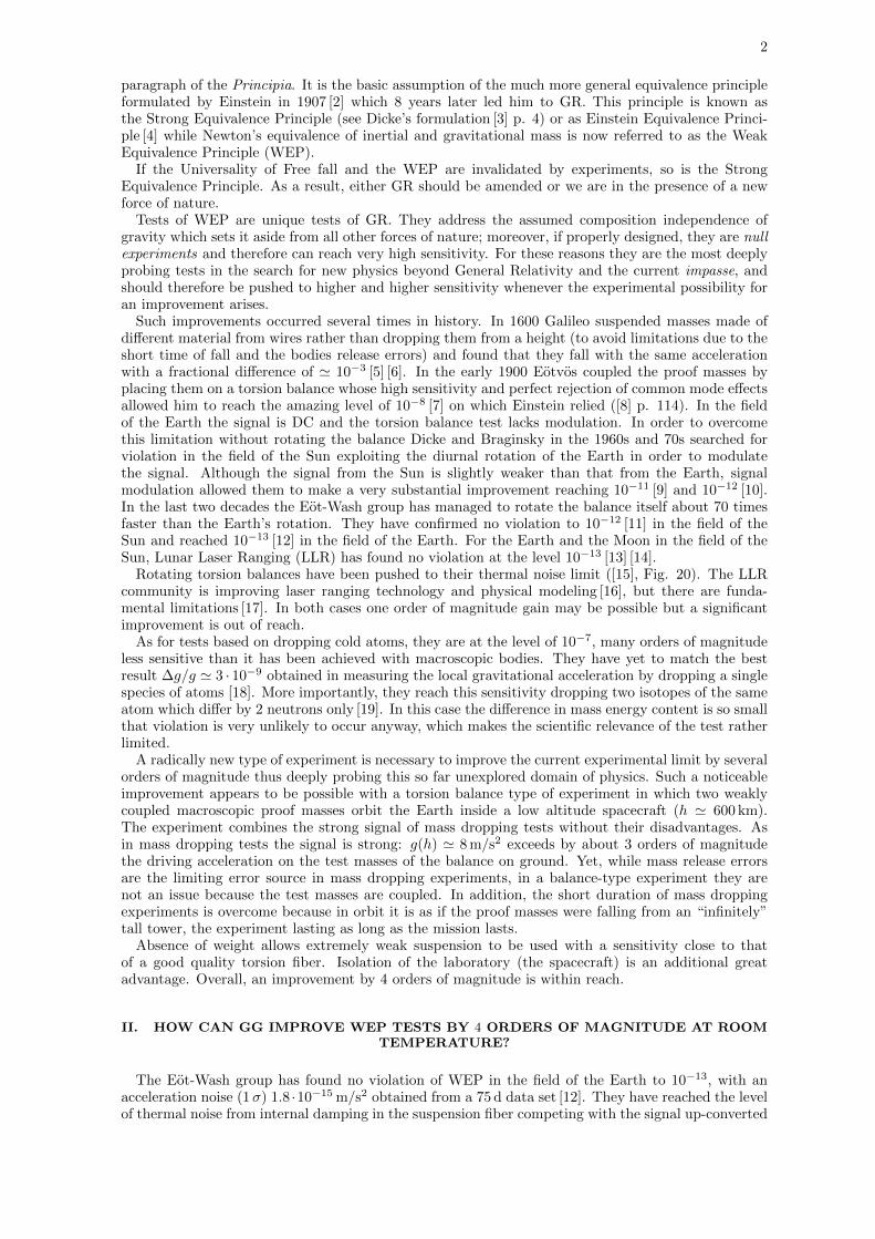
In [1] it has been demonstrated how the 1/√f dependence of structural thermal noise affects a 2D
mechanical oscillator rotating above its natural (resonance) frequency like GG. We therefore quanti-tatively compare in Fig. 1 the GG and µSCOPE thermal noise (µSCOPE is a 1D rotating oscillatorsimilar to the torsion balance in this respect) on the basis of the signal modulation frequency only.
Anna, 24 June 2011: updated 15 February 2012
3
Let us use this plot to compare GG with Microscope
Figure 2: The inclined line is the spectral density (SD, in arbitrary units) of the thermal noise in case of structural
(internal) damping as expected if measured in the system in which the springs (or fiber) are at rest. It has the 1/�𝑓𝑓 behavior (Saulson, 1990). GG and Microscope if not spinning are affected by an EP violation signal in the field of the Earth at their orbital frequency 1.7 ⋅ 10−4 𝐻𝐻𝐻𝐻; assuming that all other parameters relevant to thermal noise are the same, as far as the frequency dependence of internal damping are concerned they are located at the black spot. Microscope rotates so as to upconvert this signal(according to the authors) to a slightly higher frequency 8 ⋅10−4 𝐻𝐻𝐻𝐻; on the internal damping line line this brings its thermal noise at a lower level, represented by the blue spot. GG spins at 1 𝐻𝐻𝐻𝐻 and therefore upconvertes an EP violation signal in the field of the Earth to (1 ± 1.7 ⋅ 10−4 ) 𝐻𝐻𝐻𝐻 ≃1 𝐻𝐻𝐻𝐻, which brings its thermal noise to the red spot, at a value a factor 35 times smaller. The larger mass of the test bodies and higher 𝑄𝑄 (at this high frequency) provide an even smaller thermal noise in w.r.t Microscope (despite the fact the natural frequency is higher) . Overall, this leads to a very short integration time even for a target violation signal 100 times smaller. (give the value of integration time in the two cases, quoting the Microscope paper)
GG & µSCOPE not spinning: thermal noise @ 𝑓𝑓𝐸𝐸𝐸𝐸 ≃ 1.7 ∙ 10−4 Hz of violation signal from Earth
µSCOPE spinning: thermal noise @ 𝑓𝑓𝐸𝐸𝐸𝐸 ≃ 8 ∙ 10−4 Hz of violation signal from Earth
GG spinning: thermal noise @ 𝑓𝑓𝐸𝐸𝐸𝐸 ≃ 1 Hz of violation signal from Earth
FIG. 1: The inclined line shows –in arbitrary units– the linear Spectral Density (SD) of the structural (internal)damping thermal noise as function of frequency, measured in the system in which the suspensions are at rest.The expected 1/
√f behavior [21] has been confirmed experimentally by the rotating torsion balances (see
[15], Fig. 20 where the predicted 1/√f behavior is also shown as a black straight line). If they were not
spinning, GG and µSCOPE would be affected by a violation of UFF/WEP in the field of the Earth at theirorbital frequency ' 1.7 · 10−4 Hz. As far as the frequency dependence of internal damping is concerned,their thermal noise would be the same, and it is depicted by the black bullet. However, once they are setin rotation, µSCOPE (1D sensor) up-converts the expected signal to νµscope ' 8 · 10−4 Hz while GG (2Dsensor) up-converts it to νspin ' 1 Hz. On the internal damping straight line the corresponding thermal noiseis represented by the blue and the red bullet respectively. The advantage of a higher rotation frequency is
apparent: it makes the linear Spectral Density of GG thermal noise a factor√νµscope/νspin ' 35.4 times
smaller than that of µSCOPE. At a given frequency of the signal, thermal noise competing with it is a randomnoise, and therefore it decreases as the square root of the integration time. We conclude that, because ofrotation only, the integration time required for GG to reduce thermal noise below a target signal is a factorνµscope/νspin ' 1250 shorter than the integration time needed for µSCOPE to do the same.
4
According to the Principal Investigator [20], µSCOPE is expected to be limited by thermal noisedue internal damping in the gold wire of 5µm diameter and 2.5 cm length which connects the testmasses to the instrument cages. At the signal frequency νµscope ' 8 ·10−4 Hz it is estimated to amount
to 1.4 · 10−12 ms−2/√
Hz ([20], Table 5). With the target ηµscope = 10−15 and for a signal-to-noiseratio SNR = 2 the required integration time is tint−µscope ' 1.23 · 105 s = 1.4 d, i.e. the mission goalcan be reached in 20.8 orbits of the satellite (as stated also in [22], p. 16). Should µSCOPE aim at10−17 like GG it would require a 104 times longer integration time (about 39 yr) which is obviouslyunfeasible.
For GG the thermal noise force per unit of reduced mass competing with the signal after an inte-gration time tint is given in [1] and reads:
ath'
√4KBTω2
dφ(ωspin)
µωspin
1√tint
(1)
where T ' 300 K is the equilibrium temperature; KB = 1.38 · 10−23 J/K is the Boltzmann constantand (for GG) ωspin ' 2π rad/s is the spin angular frequency; µ = m/2 = 5 kg is the reduced massof the oscillator (m = 10 kg is the mass of each test cylinder); ωd ' 2π/540 rad/s is the naturaldifferential frequency; φ(ωspin) ' 1/20000 is the loss angle due to internal losses in the proof massessuspensions at the spin frequency. Large test masses are chosen in order to reduce thermal noise,and in consideration of the fact that rotation makes the effects of mass anomalies DC, while it up-converts the signal to the (high) spin frequency. U-shape laminar suspensions will be manufactured inCuBe because this alloy, if properly treated, is known to have a good mechanical quality. A naturaldifferential period of 540 s can be obtained with U-shape CuBe flexures that can be manufactured,tested and launched safely (ωd =
√k/µ, k being the elastic coupling constant of the proof masses in
each direction of the sensitive plane). A rotation frequency of 1 Hz is a standard rotation frequencyfor spin stabilized spacecraft. Near this frequency loss angles close to 1/20000 have been measured[23] [24].
Note that formulas in all similar to (1) are used to calculate the thermal noise of the rotatingtorsion balance [15] as well as of µSCOPE [20]. For GG, with the target η
GG= 10−17 and SNR = 2
the required integration time is only about 1 h. Taking into account also thermal noise due to residualgas damping and to eddy currents we find that a total integration time of about 3 h is needed, with10−5 Pa residual pressure, 2 cm gap and a factor 100 reduction of the magnetic field of the Earth tobe provided by a µ-metal shield [25]. It is planned that a full test to η
GG= 10−17 will be performed
with 1 d measurement data. Thus all the available time (in a total 9-month mission duration) canbe devoted to checking for systematic errors under varying dynamical conditions –provided naturallyby the spin axis of the satellite being fixed in space (by conservation laws) while the orbit planeobeys the ' 1o/d regression of the nodes of sun-synchronous orbits– which will allow the expectedviolation signal to be separated beyond question, with one accelerometer only, from competing effectsof classical physics due to their different known signature [26].
Scientists agree on the advantages of up-converting a low frequency (or DC) signal to higher fre-quency (the higher the better) by rotating the oscillator used to measure it. However, modulationby rapid rotation is known to face two major problems. The primary one is that in the case of 1Dmechanical oscillators the effect of a force up-converted above the natural frequency of the oscillatoris reduced as the ratio natural-to-signal frequency squared. Precisely for this reason 1D oscillators areused to suspend the mirrors of the VIRGO gravitational wave laser inteferometer detector where thepurpose is to reduce the effects of microseismic terrain noise at frequencies higher than the resonancefrequency of the oscillator. Secondly, rotating macroscopic bodies are affected by unbalance effectswhich at a first glance are expected to be higher at higher rotation frequencies.
These problems are typical of 1D oscillators, but they disappear in 2D oscillators like GG in whichtwo concentric coaxial cylinders are weakly coupled with elastic constant k in each direction of theplane perpendicular to the symmetry axis and rotate around it with angular velocity ωspin. Thegeneral solution of the equations of motion (in the inertial not rotating reference frame) for therelative position vector ~r(t) of the test masses (with ωspin much higher than both the frequency ofthe force signal and the natural frequency of the system) is given by [1]:
~r(t) ' −~ε(
ωdωspin
)2(cos(ωspint+ ϕ)sin(ωspint+ ϕ)
)+~F
k− φ(ωspin)
~ωspinωspin
×~F
k+
+A0eφ(ωspin)ωdt/2
(cos(ωdt+ ϕA)sin(ωdt+ ϕA)
)+B0e
−φ(ωspin)ωdt/2
(cos(−ωdt+ ϕB)sin(−ωdt+ ϕB)
) (2)
where ~F is the external (differential) force acting between the masses in the plane of the oscillatorat very low frequency (we consider it DC) and ~ε is the offset vector from the rotation axis due to
5
inevitable construction errors. ~ε is fixed on the rotating oscillator. A rotating mechanical systemdescribed by these equations is known in rotordynamics as being in supercritical regime, to indicatethat the rotation speed is higher than the natural –or critical– one (the resonance). The solution (2)is approximate in that terms depending on the loss angle squared have been neglected. Such terms arecertainly negligible in the GG case. Eq. (2) is simplified also because it does not take into account theactual 3 dimensional shape of the proof masses as hollow cylinders. In that case conical modes of thesymmetry axes appear. However, it is known from the general theory of supercritical rotors, and ithas been confirmed in this specific case, that conical modes are naturally damped and do not give riseto any instability (see [27] Sec. 3.2 and [23] Ch. 6). We can therefore consider (2) as representativeof the main features of the dynamical behavior of the real system.
If no external force is applied and there are no losses, that is the loss angle φ(ωspin) is zero, only thefirst term in (2) is non zero. The solution is the equilibrium position fixed in the rotating frame at adistance from the rotation axis smaller than the original offset ε by the factor (ωspin/ωd)
2 = 2.9 ·105 inGG. This is the auto-centered equilibrium position, whereby it is apparent that –contrary to commonintuition– the faster is the spin (compared to the natural frequency) the better the masses auto-centeron one another. If the offset error of the GG test masses is 20µm –which is feasible– they will auto-center to 70 pm, thus reducing very effectively and with no need for an active control classical gravitygradient (tidal) effects. The minus sign is very important. It shows that the equilibrium positionis located on the rotor at the opposite direction of the original offset vector ~ε. Therefore it can bereached only if motion is allowed in 2D ([28], Ch. 6).
If an external differential force ~F is applied (still with no losses) the second term of (2) is nonzero, while all the remaining ones are zero. The second term shows that the effect of the force is a
differential displacement vector of the proof masses relative to each other, equal to ~F/k just as in thecase in which the oscillator is not rotating. Therefore, even in the case in which the rotation of theoscillator up-converts the frequency of the applied force above the natural frequency of the oscillator
(the resonance frequency), the effect of the force is still ~F/k thus showing that no attenuation occursin the response of the oscillator. In the case of a 1D rotating oscillator with the same natural androtation frequencies the response to the same force would drop off as (ωd/ωspin)2. If such attenuationwere to occur in GG the strength of the displacement signal when the system rotates would be a factor2.9 · 105 smaller than it is at zero spin!
With the “GG on Ground” (GGG) prototype (see Sec. IV), which is a 2D oscillator like GG, wehave demonstrated experimentally that the response to a low frequency signal is indeed not attenuatedwhen the oscillator rotates and up-converts it above the natural frequency. The result of this test isreported in Fig. 2 and described in the caption [31].
In the presence of losses the response to the external force ~F shows a difference from the zero spincase. That is given by the third term in (2). It represents a displacement in the sensitive plane ofthe oscillator perpendicular to the applied force, but its size is smaller than the displacement in thedirection of the force by a factor equal to the loss angle. The relevant losses are those at the spinfrequency, which is another advantage of rapid rotation because losses are known to be smaller athigher frequencies than at lower ones (see e.g. [24]). In GG using CuBe joints with an appropriatemanufacturing procedure and a loss angle ' 1/20000 @ 1 Hz the displacement perpendicular to theapplied force is irrelevant.
In the general solution (2) the main effect of losses is expressed by the last 2 terms. They showthat in the inertial reference frame the oscillator performs a combination of a forward and a backwardorbital motion –known as whirl motion, with amplitudes and phases determined by initial conditions–at the (slow) natural frequency ωd, and that the radii of such orbits are exponentially decaying inthe case of the backward whirl and exponentially growing in the case of the forward one. Since thetime constant is proportional to the (small) value of φ(ωspin) the exponentially growing whirl is aweak instability. Every natural/whirl period the radius of the forward whirl grows by the fractionπφ(ωspin), hence the tangential force which produces the growth is –in modulus– krφ(ωspin), whichis a very small fraction of the elastic force, requiring a correspondingly small force to stabilize it. Itsfrequency is the natural one and does not interfere with the signal ([30] [29]). In the GGG prototypeforward whirl motion is routinely controlled.
Small force experiments need very low ωd for high sensitivity and very fast rotation in order to movethe signal to a much higher frequency where thermal noise is much lower. This is the very definitionof a rotor in supercritical regime, which in turn is known to require 2 degrees of freedom. This showswhy a 2D rotating oscillator suits UFF/WEP tests while one limited to 1D does not.
It should be noticed for completeness that in 1D rotation would attenuate response to both the signaland the competing thermal noise. Hence, with a very good readout one can in principle overcome theattenuated response to the signal (readout electronics 1/f noise is also reduced at higher frequencies).However, in presence of many orders of magnitude attenuation it may be very hard to devise an
6
FIG. 2: GGG measurements showing that in a 2D oscillator in supercritical rotation modulation of lowfrequency signals by rotation at a frequency above resonance can be performed without the response of theoscillator being attenuated. Left: GGG is not rotating and a differential force signal of about 2 · 10−7 N at0.01 Hz is applied to the test cylinders along the Xlab direction of the horizontal plane of the lab. In thisdirection the natural oscillation frequency of the test cylinders relative to each other is νx = 0.124 Hz, thusthe force is applied below the resonance. (We add that the natural oscillation frequency in the perpendiculardirection is νy = 0.063 Hz). Right: GGG has been set in rotation at νspin = 0.19 Hz, the natural oscillationfrequency during rotation is νw =
√(ν2x + ν2y)/2 = 0.098 Hz and the same force signal is applied, in the
same direction Xlab. The force signal is up-converted by rotation above the GGG natural frequency. Theexperimental data have been demodulated back to the non rotating horizontal plane of the lab for comparisonwith the non rotating case shown before. If GGG were an oscillator in 1D, a similar rotation above its naturalfrequency would have attenuated its response to the signal by a factor 2.56, which would have been easilyappreciated. We can see that in the non rotating case (left plot) noise at lower frequencies is higher. Thereal advantage is to up-convert above resonance a signal at very low frequency, where noise in absence ofrotation is considerably higher. Which is the case with GGG and GG. In the test presented here the forcewas applied at a not so low frequency so that it could be performed with a short duration run. The purposewas to demonstrate experimentally that rotating a 2D oscillator does up-convert a signal to frequencies aboveresonance without reducing the response of the oscillator to the signal.
adequate readout. As a general rule, reducing the response to the signal in a small force experimentis not a good strategy.
III. THE IDEAS BEHIND GG
GG is designed by the need to fulfill the following main drivers of a UFF/WEP experiment in space:1. the test masses should be weakly coupled for high sensitivity (the weaker the better); 2. the apparatusshould rotate in order to modulate the signal at high frequency (the higher the better); 3. the testmasses should have high common mode rejection (the higher the better) because the violation signal isdifferential while in space there is a large common mode inertial force (mainly due to residual air dragon the spacecraft); 4. in low Earth orbit the two bodies of different composition should be concentricin order to reduce classical gravity gradient –or tidal– effects (the more concentric, the better).
As for driver no. 4 there is general agreement that the test bodies should be concentric coaxialcylinders. The question is: should the symmetry axis of the cylinders lie in the orbit plane or shouldit be perpendicular to this plane? In the first case the symmetry axis is the sensitive axis, i.e.the accelerometer is a 1D oscillator to be rotated around a non-symmetry axis. In the second casethe concentric cylinders form a 2D oscillator in the orbit plane rotating around the symmetry axisperpendicular to it. If the strategy is to actively control the test cylinders to prevent their motionand keep them concentric –in which case the signal is contained in the control force itself– then it iseasier to control one direction only, and therefore the natural choice is the first one (as in STEP [32]and µSCOPE [33]). From this choice it follows that rotation perpendicularly to the symmetry axismust be provided actively.
However, each test mass forms a 2-body problem with the Earth, and therefore it has 2 degrees offreedom (in the orbital plane). UFF/WEP experiments are required to measure tiny relative deviationsof the two masses from the same orbit that they should follow according to classical celestial mechanics.The test masses are very weakly suspended because if they were totally free the experiment wouldbe limited by release errors ([34] [35]), but in essence we deal with a 2-body problem. If the masses
7
FIG. 3: The sketch shows a section of the GG test cylinders in the plane of the orbit around the Earth atabout 600 km altitude at the start of the mission with the symmetry/spin axes perpendicular to it (figure notto scale). Each cylinder spins around its symmetry axis at ωs ' 2π rad/s while orbiting around the Earth atωGG = 2πνGG = 2π1.7 · 10−4 rad/s. A violation of the weak equivalence principle would result in a differentialdisplacement vector ∆~rEP pointing to the center of the Earth. For the GG target η = 10−17 and a differentialcoupling frequency νd ' 1/540 s−1 it is ∆rEP = 8 · 10−17/(2π/540)2 ' 0.6 pm. The test cylinders, the weakmechanical joints which couple them and the laser gauge readout all corotate at ωs � ωGG thus up-convertingand reading the signal at ' ωs ' 2π rad/s.
are forced to move along one direction only (the sensitive axis) by making the suspensions very stiffin the other two directions, the cross coupling of such high stiffness with the sensitive axis while themasses tend to move in a plane (motion along the sensitive axis being prevented by active control)is a serious issue ([36] [37]). From a general physics viewpoint it is much better to have a mechanicaloscillator sensitive in the orbit plane too (as in GG) free to respond to external forces whose effect ismeasured by a good readout, auto-centering being ensured by physics laws.
In addition, the oscillator would rotate around its symmetry axis rather than perpendicularly to it;and by making the whole spacecraft cylindrically symmetric and co-rotating it is possible to stabilize itpassively simply by providing –at the start of the mission– the required spin frequency. Weak couplingof the spacecraft outer shell with the payload inside it provides the so called nutation damping requiredfor one-axis attitude stability.
Fig. 3 shows a sketch of the GG test cylinders in the orbit plane around the Earth in the presence ofa violation signal. In this configuration disturbances along the cylinders’ axes, such as the radiometereffect, are not a limitation. In 1D sensors the radiometer effect, caused by the residual gas in combina-tion with temperature gradients across the axes of the cylinders, is a well known differential systematiceffect competing directly with the violation signal which sets severe requirements ([38] [39]).
Drivers no. 1 and 2 require very weak coupling and very fast spin, which is the definition of amechanical oscillator rotating in supercritical regime. As we have seen in Sec. II this is possible in 2D(not in 1D), it provides a very effective auto-centering of the test masses by physics laws and a highlyreduced level of thermal noise, resulting in a very short integration time even for a UFF/WEP testto 10−17 at room temperature.
Drag on GG due to residual atmosphere along its orbit is 50 million times smaller than 1-g, but itis also 2.5 billion times bigger than the target signal. Its effect is an inertial force on the suspendedtest masses which ideally should act the same on both of them (common mode effect). In reality it isnot so; a good strategy is to partially compensate and partially reject it. A drag free control systemfor GG has been developed in 2009 by TAS-I (Torino) based on GOCE expertise ([40] Ch. 7). For thethrusters technology i both FEEP and Cold Gas thrusters were considered. In 2011 a delta study hasbeen performed by TAS-I establishing Cold Gas thrusters as the baseline [41].
In order to reject common mode forces (driver no. 3) we would like the cylinders to be coupled like ina balance. With mechanical suspensions this is possible, though not trivial. A very imaginative designhas been proposed by D. Bramanti in 1998 ([23] Ch. 2 Fig. 2.7) and updated in 2009 ([40] Ch. 3): theconcentric cylinders are arranged to form a peculiar beam balance with the beam along the cylindersaxis made by appropriate coupling arms which can be adjusted with inch worm actuators in orderto balance the balance. The whole design is perfectly symmetric w.r.t. the center of mass both inazimuth (cylindrical symmetry) and top/down. The common mode force against which balancing is
8
performed is the inertial force resulting from air drag on the spacecraft.On ground against 1-g beam balances are balanced to 5 parts in 1010 [42]. In GG the force
to be balanced is 50 million times smaller than 1-g and the required level of balance (rejection ofcommon mode forces) is by 1 part in 105 ([40], Sec. 4). The mechanical suspensions are very weakU-shape lamellae (a 10 kg proof mass inside GG requires a suspension that one would use on groundfor suspending 0.2 milligram against local gravity). They provide also passive electric discharging ofthe test masses, which is crucial in gravity experiments, but unlike dummy wires like those used todischarge the test bodies of µSCOPE, in GG they couple the masses in a well designed manner andensure a small value of the relevant losses (1/20000).
After drag free control, rejection of the remaining drag effect by the GG balance is very effective,hence only a very small fraction produces a differential displacement of the test cylinders while mostof it acts the same on both of them. The readout must be insensitive to this common mode effect,otherwise it may be detected as differential –to some extent– and therefore compete with the signal.The great property of torsion balances on ground, whereby the center of mass is necessarily alignedwith the fiber and common mode forces are perfectly rejected does not hold if the balance is at 0-g.In space we need both rejection of common mode forces by the test masses and a differential readout.
The original GG readout was based on capacitance bridges, whose plates must be carefully centeredhalfway in between the test cylinders to ensure that its reading is not affected by their displacementsin common mode. A laser gauge interferometry readout developed and tested at JPL with the noiselevel of ' 1 pm/
√Hz @ 1 Hz will replace the capacitance bridges because it is less noisy and it ensures
a better differential reading. In addition it allows a larger gap between the cylinders (2 cm), makingelectric patch effects negligible and reducing thermal noise due to gas damping. Last but not least,it deposits only light on the test cylinders. In order to measure the relative displacements of the testcylinders 3 laser gauges will be mounted at 120o from each other. The laser boxes will be locatedon the co-rotating intermediate stage (known as PGB) which encloses the test masses. Two layersof laser gauges, one above and one below the center of mass, will be used for full information on therelative motion of the test cylinders. In correspondence of each laser beam the outer test cylinderwill have a hole surrounded by a well polished reflective annular surface, and the inner test cylinderwill have a small area also well polished and reflective. A similar system will be implemented on theground prototype; 30 times higher noise level is acceptable in this case.
IV. GG ON GROUND: CURRENT SENSITIVITY AND TARGET
GGG (“GG on Ground”) is a 1-g version of the 2D differential accelerometer to fly in GG. It issensitive in the horizontal plane of the lab where the concentric coaxial test cylinders (10 kg each asin space) are weakly coupled while rotation occurs around the vertical/symmetry axis. The same 2Djoints which couple the masses in the horizontal plane suspend them against local gravity. As a con-sequence, coupling cannot be as weak as in absence of weight, which results in a reduced accelerationsensitivity as compared to the apparatus in space (by the ratio of the natural coupling frequenciessquared). GGG is in essence a very peculiar beam balance –first proposed by D. Bramanti [23] Ch. 3–with a vertical (rather than horizontal) beam and the masses concentric (rather than separated by thebeam). These properties allow rotation around the (vertical) beam of the balance at frequencies higherthan the natural one which couples the masses; thus the GGG dynamical system is in supercriticalregime as required in space.
The essence of the GGG design is sketched in Fig. 4 and described in the caption. The differentialperiod Td of natural oscillation of the test bodies relative to each other can be written as:
T 2d '
4π2
kt+kc+kb2mL2 − g
2L∆LL
(3)
(m the mass of each test body, g the local gravitational acceleration, L half the length of the balancecoupling arm, ∆L/L the level of unbalance of the balance, kt, kc, kb the elastic constants in [Nm/rad]–along each direction– of the 2D flexure joints sketched in the figure). The term depending on gravityin the denominator of (3) can be reduced by making ∆L/L sufficiently small, i.e. by sufficientlybalancing the balance via adjustments of its arms length. In practice, in GGG it is easier to adjustthe masses of the balance rather than its arms; with 10 kg bodies, the required balancing depends ondisplacing sizable additional masses. The term depending on local gravity could in principle be usedto obtain, with the same joints, a longer differential period (gravity would act as a negative spring)but this is in general non convenient as far as tilts are concerned; one should also avoid the system tobecome unstable.
9
L+ L∆
m
θshaft
L
θca
kshaft
kt
kc
kb
m
θtilt
b
FIG. 4: The GGG accelerometer is designed to be sensitive to differential forces acting in the horizontal planeof the lab while rotating in the vertical direction. (left) The two test masses depicted in blue and green arecoupled by 2D weak joints to form a vertical beam balance. The coupling arm of the balance is shown (inblack) with the 3 joints (in red). The central joint, of elastic constant kc, sustains the whole weight and isthe pivot center of the balance; the top and bottom joints, of elastic constants kt and kb, suspend the top andbottom mass respectively. The sketch refers to an unbalanced configuration of the balance in which the bottomhalf of the arm has length L while the top one is slightly longer, with length L+ ∆L. In this case the naturalperiod of differential oscillation of the test masses Td is given by (3). In the real GGG apparatus the masses areconcentric coaxial Al cylinders weighing 10 kg each. (right): The upper part of the shaft, rotating on bearingsb is tilted by the angle θtilt due to terrain and bearings tilt noise. A 2D flexure joint kshaft is placed on theshaft below the bearings. It suspends the balance of total mass Mtot with an arm of length Lshaft –fromthe joint kshaft to the pivot center of the balance where the central joint kc is located. At low frequencies,
in response to an input tilt angle θtilt the shaft is subject to a reduced tilt θshaft =kshaft
MtotgLshaftθtilt � θtilt.
The corresponding equilibrium position of the coupling arm of the balance in response to the shaft tilt is
θca = kc2mL2
T2d
4π2 θshaft. Note that low frequency horizontal acceleration disturbances are equivalent to tiltdisturbances (∆ahoriz−acc = gθtilt).
1
3
17
18
19
6
8
10
2r
4r
5r
7r
9r
11r
12r 13r
14r
15r
16r
FIG. 5: In order to isolate the GGG rotating accelerometer from low frequency terrain and ball bearingsnoise (tilts as well as horizontal accelerations) the current design (left) exploits the attenuation provided atlow frequencies by the 2D flexible joint (labeled 11r –r refers to a rotating component) isolating the upperpart of the shaft (9r) –which is subject to ground tilts and ball bearings (8) noise– from the lower part (12r)which holds the GGG balance. Thus, the isolated part of the shaft (12r) is driven by its weight closer to thedirection of local gravity (which defines the vertical direction) more than its tilted top part. The picture tothe right shows the experimental apparatus while opening the vacuum chamber.
An additional 2D weak joint with elastic constant kshaft has recently been mounted below the
10
FIG. 6: Time series of the relative displacements of the GGG test masses (frequencies above 1 mHz filteredout) in one direction of the horizontal plane of the lab during a 29 d run (stopped by the earthquake of 25January 2012 with epicenter in Northern Italy).
bearings on the rotating shaft with the purpose of passively reducing low frequency noise on the shaftdue to terrain and bearings tilt and horizontal acceleration noise (Fig. 4, right and Fig. 5, left). Theexperimental results obtained with this system in supercritical rotation at ' 0.2 Hz in a 29 d run arereported in Figs. 6 and 7 after demodulation to the non rotating horizontal plane of the lab. Duringthe run the vacuum chamber is thermally stabilized; low frequency ambient temperature variationsare reduced by 2 orders of magnitude.
Fig. 6 reports the time series of the relative displacements between the centers of mass of the testcylinders, showing that they remain close to each other within a few tens of nanometer for the entireduration of the run. As shown in Fig. 7 (bottom) the relative displacement noise at the frequency1.7 · 10−4 Hz relevant for the GG experiment in space is ' 180 pm, which is 300 times larger than thetarget in space. Due to the current much stiffer coupling of the GGG test masses the correspondingacceleration noise is ' 7 · 10−11 m/s2, but we argue that there are no fundamental limitations toreducing it very significantly.
We state by the following arguments that GGG acceleration noise is currently limited by ballbearings tilt noise on the shaft. Input tilts θtilt and the resulting differential acceleration atilt betweenthe test cylinders are related (at low frequencies) by a simple analytical expression:
atilt =kcmgL
kshaftMtotgLshaft
gθtilt (4)
(see Fig. 4, right, for definition of the symbols) where all quantities except θtilt = θterrain+θballbearingare measured directly. Low frequency terrain tilts are not easy to measure; however, we rely on carefulmeasurements carried out with various ISA (Italian Spring Accelerometer) instruments at IAPS lab(Roma Tor Vergata) [44] and at a former LABEN lab downtown Florence [43] (Ch. 7) to obtain areliable estimate of the input tilt noise at the current INFN-GGG lab in Pisa-San Piero a Grado.With this estimate for θterrain, using (4) and the measured acceleration noise between the proofmasses we conclude that low frequency ball bearings noise is about 2 orders of magnitude bigger thanterrain tilt noise (readout noise not being the limiting factor). From the ratio atilt/(gθtilt) we alsoconclude that –at the frequency of interest– input tilt noise has been reduced by almost 5 orders ofmagnitude.
GGG acceleration noise due to input tilt noise can be further reduced by several orders of magnitude.In particular, low frequency tilt noise on the rotating shaft due to the bearings can be reduced belowthe local terrain tilt noise by using air bearings instead of ball bearings. Though we are using ceramicball bearings, they are known to be several orders of magnitude more noisy than air bearings. Forinstance, the entire vacuum chamber enclosing the torsion balance of the Eot-Wash experiments rotateson air bearings. In GGG this would be unpractical, hence we must solve the problem of a rotatingshaft going from air to vacuum. Commercial solutions are available for this problem which can be
11
FIG. 7: GGG noise performance as measured from a 29 d run. Top: Spectral density of the relative displace-ments and acceleration of the test cylinders in one direction of the horizontal plane of the lab; the GGG differ-ential accelerometer is spinning at νspin = 0.19 Hz with natural coupling frequency of 0.1 Hz. The measured
relative displacement is ' 1.8 · 10−7m/√
Hz and the measured relative acceleration is ' 6 · 10−8ms−2/√
Hzat the frequency νGG ' 1.7 · 10−4 Hz, the orbital frequency relevant for GG in space. Bottom: measuredrelative test masses displacement and acceleration noise integrated over the full run duration. At νGG weget an integrated differential displacement noise of ' 1.8 · 10−10 m and a differential acceleration noise of' 7 · 10−11 m/s2.
adapted to the GGG case. Once bearings noise is smaller than local terrain tilt noise, various physicalquantities in (4) can be optimized to further reduce the effect of terrain tilts on the test masses.
Though terrain tilt and bearings noise is absent in the space experiment (high rotation energy,spacecraft isolation, absence of motor and bearings) on ground this noise must be drastically reducedin order to demonstrate a performance close to that required in space. It is quite interesting that thereappear to be no fundamental limitations to setting for GGG the task of measuring an accelerationnoise only 10 times larger than required for GG in space, namely 8 · 10−16 m/s2 at the GG orbitalfrequency (up-converted by rotation to 0.2÷ 3 Hz). The error budget reported in Table I shows thatfor a 30 d integration time thermal noise is not a limitation. However, several important improvementsare required to reduce tilts and bearings noise, weaker suspensions and good balancing are needed toreach a longer differential period. A laser gauge readout similar to that planned for GG in space willbe implemented with a noise level of 30 pm/
√Hz at the rotation frequency.
12
GGG goal vs GG goal in space
Differential acceleration be-tween test masses
a [ms−2] r = aT2d
4π2 [m] IntegrationtimeTint [d]
a @ 1.7 · 10−4 Hz
GG goal in space aGG = ηg(h) 8 · 10−17 6 · 10−13 1
(upconverted to 1 Hz) (η = 10−17 , h ' 600 km) (Td ' 540 s)
GGG aGGG = 10aGG 8 · 10−16 3.2 · 10−14 30
goal (upconverted to 0.2÷ 3 Hz) (Td ' 40 s)
GGonGround noise budget @ 1.7 · 10−4 Hz
Noise Source ∆a Integrated ∆a ∆r Integrated ∆r Conditions and physical data
eddy currents 1.3 0.8 0.5 0.3 no µmetal magnetic shield
residual gas 0.5 0.3 0.2 0.1 2 cm gap, P = 10−4 Pa
ReadOut noise: aROnoise = (4π2/T 2d )rROnoise
laser gauge 7.4 4.6 3.0 1.8 Td ' 40 s
Total noise 12 7.4 4.8 3.0
TABLE I: GGG goal and noise budget. The top part of the table shows the goal of GG in space and that ofGGG on ground, with their relevant physical parameters. The bottom part of the table shows the error budgetof GGG to reach its goal. We can see that terrain and bearings tilts and readout noise are the dominant noisesources, while thermal noise (from internal damping, residual gas and eddy currents) is lower. The relevantphysical parameters used in the calculations are reported with the symbols as defined in Sec. IV.
V. CONCLUSIONS
GG can test gravity for composition dependence 4 orders of magnitude better than to-date whileorbiting around the Earth on a low altitude sun-synchronous orbit. It will test the Universality of Free
Fall and the Weak Equivalence Principle in the field of the Earth to 1 part in 1017
by searching for adifferential acceleration signal of ' 8 · 10−17 m/s2 between proof masses of different composition. Thesignal (a 0.6 pm relative displacement of the masses) points to the center of mass of the Earth at thesatellite orbital frequency 1.7·10−4 Hz and is up-converted to 1 Hz by its own rotation. The experimentis performed at room temperature because the relevant thermal noise is very low thanks to GG rapidrotation. Therefore, the integration time required to bring thermal noise below the signal and reachthe mission goal is very short (a few hours). A low noise laser gauge readout developed and tested atJPL makes it possible to measure the target signal in such a short integration time. By allowing forabout 15 satellite orbits (which take one day) to complete a single test, most of the mission durationtime is available to establish with certainty the physical nature of the measurement by checking itagainst systematics. These checks rely on different dynamical conditions (of the sensor relative tothe orbital plane) during the mission. They are performed with a single accelerometer located at thecenter of mass of the spacecraft, they are very robust and make additional accelerometers unnecessary.
An agreement exists between ASI (Agenzia Spaziale Italiana) and JPL (Jet Propulsion Laboratory)on submitting GG to the EXPLORER program of NASA as an American led mission with Italianpartnership. EXPLORER is a very successful program dedicated to flying small size missions everyfew years; it has been highly ranked by the 2010 Decadal Astronomy Survey. Recently, GG has beensubmitted in response to an ESA Call for a small mission opportunity to fly in 2017.
A very strong asset for GG is the GGG full scale prototype in the lab. On ground the major errorsources are terrain microseismic and bearings noise at low frequencies, both absent in space. We have
13
recently designed and implemented on the rotating shaft a passive 2D joint for their attenuation, andmeasured a realtive displacement of ' 180 pm, corresponding to a differential acceleration noise of' 7 · 10−11 m/s2 (at 1.7 · 10−4 Hz, up-converted by rotation to ' 0.2 Hz). It is limited by ball bearingstilt noise. GGG error budget shows that along these lines there are no fundamental limitations for thesystem to be substantially improved. Our target is to reach ' 8 · 10−16 m/s2 on ground (up-convertedby rotation to 0.2÷ 3 Hz). This would be only a factor 10 away from the sensitivity required in spacefor GG to meet its goal.
This work has been supported by ASI (Agenzia Spaziale Italiana) and INFN and it was performedin part at JPL, Caltech, under a contract with NASA. Thanks are due to the Referees, whose thoroughanalysis has helped making the paper much better than it was submitted.
[1] R. Pegna et al., Phys. Rev. Lett. 107, 200801 (2011)[2] A. Einstein, Relativitatsprinzip und die aus demselben gezogenen Folgerungen, Jahrbuch fur Radioaktivitat
und Elektronik, 4, 411-462 (1907); On the relativity principle and conclusions drawn from it, in H. M.Schwarz, Einstein’s comprehensive 1907 essay on relativity, part III, American Journal of Physics, 45 (10)899-902 (1977)
[3] R. H. Dicke, The theroretical significance of experimental relativity, Blackie and Son Ltd., London andGlasgow (1964)
[4] C. M. Will, Living Rev. Relativity, 9, 3 (2006) http://relativity.livingreviews.org/Articles/lrr-2006-3[5] F. Fuligni and V. Iafolla, in STEP Symposium, ESA WPP-115, 104 (1993)[6] D. Bramanti et al., in STEP Symposium, ESA WPP-115, 319 (1993)[7] R. V. Eotvos, D. Pekar, E. Fekete, Ann. Phys. 68, 1166 (1922)[8] A. Einstein Grundlage der allgemeinen Relativitatstheorie, Annalen der Physik (ser. 4), 49, 769822 (1916);
The Foundation of the General Theory of Relativity, in The Principle of Relativity, Dover Pub. Inc. N.Y.,USA (1952)
[9] P. G. Roll, R. Krotkov, R. H. Dicke, Ann. Phys. 26, 442517 (1964)[10] V. B. Braginsky, V. I. Panov, Sov. Phys. JEPT 34, 463466 (1972)[11] S. Baeßler et. al., Phys. Rev. Lett. 83, 3585 (1999)[12] S. Schlamminger et. al., Phys. Rev. Lett. 100, 041101 (2008)[13] J. G. Williams, S. G. Turyshev & D. H. Boggs, Phys. Rev. Lett. 93, 261101 (2004)[14] J. Mueller, F. Hoffman & L. Biskupek, Testing various facets of the equivalence principle with Lunar
Laser Ranging, Class. Quantum Grav. this issue[15] E. G. Adelberger et al., Progress in Particle and Nuclear Physics 62, 102 (2009)[16] T. W. Murphy et al., Icarus 211, 1103?08 (2011)[17] A. M. Nobili et al., General Relativity & Gravitation 40, 1533-1554 (2008)[18] A. Peters, K.Y. Chung & S. Chu, Nature 400, 949 (1999)[19] S. Fray et. al., Phys. Rev. Lett. 93, 240-404 (2004)[20] P. Touboul, Space Sci. Rev. 148 455-474 (2009)[21] P. R. Saulson, Phys. Rev. D 42, 2437-2445 (1990)[22] P. Touboul, Rencontres de Moriond and GPhyS Colloqium 2011, “Gravitational Waves and Experimental
Gravity”, http://moriond.in2p3.fr/J11/transparents/touboul.ppt , LaThuile (2011)[23] GG Phase A Study Report, ASI (1998) http://eotvos.dm.unipi.it/ggweb/phaseA[24] G. Cagnoli et al., Phys. Lett. A 255, 230-235 (1999)[25] R. Pegna et al., Integration time of high sensitive equivalence principle experiments in space, to be sub-
mitted[26] A. M. Nobili et al., Null checks in space experiments to test the equivalence principle, to be submitted[27] A. M. Nobili et al., New Astronomy 3, 175-218 (1998)[28] J. P. Den Hartog, Mechanical Vibrations, Dover Publ. Inc N.Y. 1985 (first published in 1934)[29] A. M. Nobili et al., Class. Quantum Grav. 16, 1463-1470 (1999)[30] S. H. Crandall, J. Sound Vib. 11(1), 3-18, (1970)[31] R. Pegna et al., Upconverting low frequency signals above resonance, to be submitted[32] P. W. Worden, Jr., PhD Thesis, Stanford University, Stanford (CA) (1976)[33] P. Touboul, B. Foulon, G. M. Le Clerc, ONERA TP 1998-224 and IAF-98-B.3.07 (1998)[34] J.P. Blaser, Class. Quantum Grav. 18, 2509 (2001)[35] G. L. Comandi et al., Phys. Lett. A 318, 251-269 (2003)[36] J.P. Blaser, On the motion of the STEP masses, STEP Note (2000)[37] J.P. Blaser, Motion of a STEP mass with EP-violation, STEP Note (2001)[38] A. M. Nobili et al., Phys. Rev. D Rapid Commun. 63, 101101(R) (2001)[39] A. M. Nobili et al., New Astronomy 7, 521-529 (2002)[40] GG Phase A-2 Study Report, ASI (2009)
http://eotvos.dm.unipi.it/PA2/GG%20Phase%20A-2%20Study%20Report%20April%202009.pdf[41] A. Anselmi, private communication (2011)[42] T. J. Quinn, C. C. Speake, R. S. Davis, Metrologia 23, 87-100 (1986)[43] G. L. Comandi, PhD Thesis, University of Pisa, Pisa, Italy (2004)