58
OM-20000092 Rev 1 Galileo Test Signal Generator (GTS) USER MANUAL Galileo Test Signal Generator
Galileo Test Signal Generator (GTS)
USER MANUAL
Galileo TestSignal Generator
OM-20000092 Rev 1
Galileo Test Signal Generator (GTS) User Manual
Publication Number: OM-20000092Revision Level: 1Revision Date: 2006/03/25
Limited Rights NoticeThis document is a deliverable under contract no. 9F028-4-4101/A. It contains information proprietary to NovAtel Inc., or to a third party to which NovAtel Inc. may have legal obligation to protect such information from unauthorized disclosure, use or duplication. Any disclosure, use or duplication of this document or of any of the information contained herein for other than the specific purpose for which it was disclosed is expressly prohibited outside the Government of Canada except as NovAtel Inc. may otherwise agree to in writing.
NovAtel, MiLLennium, RT-20 and RT-2 are registered trademarks of NovAtel Inc.
PAC and GPSCard are trademarks of NovAtel Inc.
All other brand names are trademarks of their respective holders.
© Copyright 2005-2006 NovAtel Inc. All rights reserved.
Unpublished rights reserved under International copyright laws.
Printed in Canada on recycled paper. Recyclable.
2 Galileo Test Signal Generator (GTS) User Manual Rev 1 Limited Rights Notice
Table of Contents
Software License 7 Warranty 9 Foreword 10
Congratulations!.................................................................................................... 10 Scope.................................................................................................................... 10
1 Introduction 111.1 Features........................................................................................................... 111.2 Accessories and Options ................................................................................. 12
2 Minimum Connections 143 Setup Considerations 16
3.1 Front Panel Functionality ................................................................................. 163.1.1 H/W Fault................................................................................................ 163.1.2 10 MHz ................................................................................................... 163.1.3 CW Mode................................................................................................ 163.1.4 Transmit Inhibit (Tx INHIBIT).................................................................. 163.1.5 Initiated Built in Test (IBIT) ..................................................................... 173.1.6 1PPS ...................................................................................................... 17
3.2 Rear Panel Functionality.................................................................................. 173.2.1 Power ..................................................................................................... 173.2.2 CW Switch .............................................................................................. 183.2.3 Navigation Data Generator..................................................................... 183.2.4 Navigation Data Generator and Message Processor ............................. 183.2.5 Code PPS Output ................................................................................... 183.2.6 1PPS Update.......................................................................................... 183.2.7 10 MHz In and 10 MHz Out .................................................................... 193.2.8 RF Out .................................................................................................... 193.2.9 IF Out...................................................................................................... 19
4 Operation 214.1 Communications with the GTS ........................................................................ 21
4.1.1 Serial Port Default Settings .................................................................... 214.1.2 Communicating Using a Remote Terminal............................................. 214.1.3 Communicating Using a Personal Computer ......................................... 21
4.2 Message Control and Data Lines..................................................................... 21
5 Messages 235.1 MP Message Structure .................................................................................... 23
5.1.1 Packet Synchronization Field ................................................................. 235.1.2 L1/E5a Indication Field ........................................................................... 235.1.3 Command Message ............................................................................... 235.1.4 Status Message...................................................................................... 295.1.5 CRC-16/CCITT Checksum Field ............................................................ 36
5.2 Error Handling.................................................................................................. 37
6 Galileo SigGen GUI 386.1 Toolbar............................................................................................................. 386.2 Windows .......................................................................................................... 38
6.2.1 Signal Control Window ........................................................................... 386.2.2 Logging Control Window ........................................................................ 416.2.3 Error Status Window............................................................................... 41
6.3 Using the Galileo SigGen GUI ......................................................................... 426.3.1 Connecting to the Message Interface of the GTS .................................. 42
Galileo Test Signal Generator (GTS) User Manual Rev 1 Limited Rights Notice 3
6.3.2 Configuring the GTS............................................................................... 436.3.3 Applying a Doppler to Output Signal ...................................................... 44
APPENDICESA Technical Specifications 46B Galileo 50C Acronyms 53 Index 55
4 Galileo Test Signal Generator (GTS) User Manual Rev 1 Limited Rights Notice
Galileo Test Signal Generator (GTS) User Manual Rev 1 Limited Rights Notice 5
Tables
1 10 MHz Reference Phase Noise ..................................................................... 192 L1 IF Bandwidth Requirements ....................................................................... 203 IF Output Phase Noise .................................................................................... 204 E5a IF Bandwidth Requirements..................................................................... 205 Packet Format ................................................................................................. 236 Packet Synchronization Field .......................................................................... 237 Packet Synchronization Field Bit Format......................................................... 238 L1/E5a Indication Field .................................................................................... 239 Command Message Fields.............................................................................. 2410 Command Message Identifier Bit Fields.......................................................... 2411 L1/E5a Control Command Bit Fields ............................................................... 2512 L1 Initialization Command Fields .................................................................... 2513 E5a Initialization Command Fields 500 SPS ................................................... 2514 E5a I Channel XB(I) Coder Initialization Field ................................................. 2615 E5a Q Channel XB(Q) Coder Initialization Field.............................................. 2616 L1/E5a Code Chip Rate and Carrier Frequency Command Fields ................. 2717 Code Chip Rate Ramp Field............................................................................ 2718 Carrier Frequency Field Bit Format ................................................................. 2719 Status Message Fields .................................................................................... 2920 Uplink Range Fields ........................................................................................ 2921 Uplink Range Code Chip Sub-Phase Field ..................................................... 3022 Uplink Range Code Chip Counter Field .......................................................... 3023 Uplink Range MSec Counter Field .................................................................. 3024 Switch Status Field .......................................................................................... 3025 Switch Status Bit Fields ................................................................................... 3126 Error Status Field............................................................................................. 3127 Error Status Bit Fields...................................................................................... 3228 Hardware Status Field ..................................................................................... 3329 Hardware Status Bit Fields .............................................................................. 3430 Reset Command Second Epoch Counter ....................................................... 3531 Hardware Reset Second Epoch Counter ........................................................ 3532 Firmware Version Number Field...................................................................... 3533 FPGA Version Number Field ........................................................................... 3534 GTS State Field ............................................................................................... 3635 GTS State Value.............................................................................................. 3636 CRC-16/CCITT Checksum Field ..................................................................... 3637 CRC-16/CCITT Checksum Field ..................................................................... 3638 CRC-16-CCITT Characteristics ....................................................................... 3739 Errors............................................................................................................... 3740 L1 and E5a MP Connector Pin-Out Descriptions ........................................... 4841 L1 and E5a Navigation Data Generator Connector Pin-Out Descriptions ...... 48

6 Galileo Test Signal Generator (GTS) User Manual Rev 1 Limited Rights Notice
Figures
1 Galileo Test Signal Generator ........................................................................ 112 Interface Block Diagram ................................................................................. 133 Typical Signal Generator Setup ...................................................................... 144 Coaxial Cable ................................................................................................. 155 Power Switch .................................................................................................. 156 Signal Generator Front Panel ......................................................................... 167 Close-up of Connectors on Rear Panel .......................................................... 178 Navigation Data Generator (left) and Power Adapter (right) .......................... 189 RS-485 Symbol Timing Diagram .................................................................... 2210 Input Command Flowchart ............................................................................. 2811 Galileo SigGen GUI ........................................................................................ 4212 COM Port Settings .......................................................................................... 4313 GTS in Reset Mode ........................................................................................ 4314 Initialize/Control Commands ........................................................................... 4415 Doppler Selection Window ............................................................................. 4416 GTS Status ..................................................................................................... 4517 GTS Dimensions ............................................................................................ 4618 Power Cable ................................................................................................... 49

Software License
Software LicenseBY INSTALLING, COPYING, OR OTHERWISE USING THE SOFTWARE PRODUCT, YOU AGREE TO BE BOUND BY THE TERMS OF THIS AGREEMENT. IF YOU DO NOT AGREE TO THE TERMS OF THIS AGREEMENT, DO NOT INSTALL, COPY OR USE THE SOFTWARE PRODUCT.
1. License: NovAtel Inc. ("NovAtel") grants you a non-exclusive, non-transferable license (not a sale) to use one copy of the enclosed NovAtel software on a single computer, and only with the product it was supplied with. You agree not to use the software for any purpose other than the due exercise of the rights and licences hereby agreed to be granted to you.
2. Copyright: NovAtel owns, or has the right to sublicense, all copyright, trade secret, patent and other proprietary rights in the software and the software is protected by national copyright laws, international treaty provisions and all other applicable national laws. You must treat the software like any other copyrighted material except that you may either (a) make one copy of the software solely for backup or archival purposes, the media of said copy shall bear labels showing all trademark and copyright notices that appear on the original copy, or (b) transfer the software to a single hard disk provided you keep the original solely for backup or archival purposes. You may not copy the product manual or written materials accompanying the software. No right is conveyed by this Agreement for the use, directly, indirectly, by implication or otherwise by Licensee of the name of NovAtel, or of any trade names or nomenclature used by NovAtel, or any other words or combinations of words proprietary to NovAtel, in connection with this Agreement, without the prior written consent of NovAtel.
3. Patent Infringement: NovAtel shall not be liable to indemnify the Licensee against any loss sustained by it as the result of any claim made or action brought by any third party for infringement of any letters patent, registered design or like instrument of privilege by reason of the use or application of the software by the Licensee or any other information supplied or to be supplied to the Licensee pursuant to the terms of this Agreement. NovAtel shall not be bound to take legal proceedings against any third party in respect of any infringement of letters patent, registered design or like instrument of privilege which may now or at any future time be owned by it. However, should NovAtel elect to take such legal proceedings, at NovAtel's request, Licensee shall co-operate reasonably with NovAtel in all legal actions concerning this license of the software under this Agreement taken against any third party by NovAtel to protect its rights in the software. NovAtel shall bear all reasonable costs and expenses incurred by Licensee in the course of co-operating with NovAtel in such legal action.
4. Restrictions: You may not: (1) copy (other than as provided for in paragraph 2), distribute, transfer, rent, lease, lend, sell or sublicense all or any portion of the software; (2) modify or prepare derivative works of the software; (3) use the software in connection with computer-based services business or publicly display visual output of the software; (4) transmit the software over a network, by telephone or electronically using any means; or (5) reverse engineer, decompile or disassemble the software. You agree to keep confidential and use your best efforts to prevent and protect the contents of the software from unauthorized disclosure or use.
5. Term and Termination: This Agreement and the rights and licences hereby granted shall continue in force in perpetuity unless terminated by NovAtel or Licensee in accordance herewith. In the event that the Licensee shall at any time during the term of this Agreement: i) be in breach of its obligations hereunder where such breach is irremediable or if capable of remedy is not remedied within 30 days of notice from NovAtel requiring its remedy; or ii) be or become bankrupt or insolvent or make any composition with its creditors or have a receiver or manager appointed of the whole or any part of its undertaking or assets or (otherwise as a solvent company for the purpose of and followed by an amalgamation or reconstruction hereunder its successor shall be bound by its obligations hereunder) commence to be wound up; or iii) be acquired or otherwise come under the direct or indirect control of a person or persons other than those controlling it, then and in any event NovAtel may forthwith by notice in writing terminate this Agreement together with the
Galileo Test Signal Generator (GTS) User Manual Rev 1 Limited Rights Notice 7

rights and licences hereby granted by NovAtel. Licensee may terminate this Agreement by providing 30 days prior written notice to NovAtel. Upon termination, for any reasons, the Licensee shall promptly, on NovAtel's request, return to NovAtel or at the election of NovAtel destroy all copies of any documents and extracts comprising or containing the software. The Licensee shall also erase any copies of the software residing on Licensee's computer equipment. Termination shall be without prejudice to the accrued rights of either party, including payments due to NovAtel. This provision shall survive termination of this Agreement howsoever arising.
6. Warranty: For 90 days from the date of shipment, NovAtel warrants that the media (for example, compact disk) on which the software is contained will be free from defects in materials and workmanship. This warranty does not cover damage caused by improper use or neglect. NovAtel does not warrant the contents of the software or that it will be error free. The software is furnished "AS IS" and without warranty as to the performance or results you may obtain by using the software. The entire risk as to the results and performance of the software is assumed by you.
7. Indemnification: NovAtel shall be under no obligation or liability of any kind (in contract, tort or otherwise and whether directly or indirectly or by way of indemnity contribution or otherwise howsoever) to the Licensee and the Licensee will indemnify and hold NovAtel harmless against all or any loss, damage, actions, costs, claims, demands and other liabilities or any kind whatsoever (direct, consequential, special or otherwise) arising directly or indirectly out of or by reason of the use by the Licensee of the software whether the same shall arise in consequence of any such infringement, deficiency, inaccuracy, error or other defect therein and whether or not involving negligence on the part of any person.
8. For software UPDATES and UPGRADES, and regular customer support, contact the NovAtel GPS Hotline at 1-800-NOVATEL (U.S. or Canada only), or 403-295-4900, or fax 403-295-4901, e-mail to [email protected], visit our website http://www.novatel.com or write to:
NOVATEL INC.CUSTOMER SERVICE DEPT.1120 - 68 AVENUE NE,CALGARY, ALBERTA, CANADA T2E 8S5
9. Disclaimer of Warranty and Limitation of Liability:
a. THE WARRANTIES IN THIS AGREEMENT REPLACE ALL OTHER WARRANTIES, EXPRESS OR IMPLIED, INCLUDING ANY WARRANTIES OF MERCHANTABILITY OR FITNESS FOR A PARTICULAR PURPOSE. NovAtel DISCLAIMS AND EXCLUDES ALL OTHER WARRANTIES. IN NO EVENT WILL NovAtel's LIABILITY OF ANY KIND INCLUDE ANY SPECIAL, INCIDENTAL OR CONSEQUENTIAL DAMAGES, INCLUDING LOST PROFITS, EVEN IF NovAtel HAS KNOWLEDGE OF THE POTENTIAL LOSS OR DAMAGE.
b. NovAtel will not be liable for any loss or damage caused by delay in furnishing the software or any other performance under this Agreement.
c. NovAtel's entire liability and your exclusive remedies for our liability of any kind (including liabil-ity for negligence) for the software covered by this Agreement and all other performance or non-performance by NovAtel under or related to this Agreement are to the remedies specified by this Agreement.
This Agreement is governed by the laws of the Province of Alberta, Canada. Each of the parties hereto irrevocably attorns to the jurisdiction of the courts of the Province of Alberta.
8 Galileo Test Signal Generator (GTS) User Manual Rev 1 Limited Rights Notice
Galileo Test Signal Generator (GTS) User Manual Rev 1 Limited Rights Notice 9
Warranty
Warranty
Unless there are other contractual agreements in place (in which case those contractual agreements will take precedence), the following warranty applies:
NovAtel Inc. warrants that its Global Positioning System (GPS) products are free from defects in materials and workmanship, subject to the conditions set forth below, for the following periods of time:
Galileo Test Signal Generator One (1) Year from date of sale
Date of sale shall mean the date of the invoice to the original customer for the product. NovAtel’s responsibility respecting this warranty is solely to product replacement or product repair at an authorized NovAtel location only. Determination of replacement or repair will be made by NovAtel personnel or by technical personnel expressly authorized by NovAtel for this purpose.
There are no user serviceable parts in the Galileo Test Signal Generator and no maintenance is required. When the status code indicates that a unit is faulty, replace with another unit and return the faulty unit to NovAtel Inc.
Once you have obtained an RMA number, you will be advised of proper shipping procedures to return any defective product. When returning any product to NovAtel, please return the defective product in the original packaging to avoid ESD and shipping damage.
Warranty Period: Subject to extended warranty provisions, Seller’s standard warranty is one (1) year from the date of delivery for production hardware and three (3) months from the date of delivery for engineering units and internal retained models. Seller warrants that during the Warranty Period, NovAtel products will be free from defects in material and workmanship, conform to applicable specifications and the software will be free from error which materially affect performance. THESE WARRANTIES ARE EXPRESSLY IN LIEU OF ALL OTHER WARRANTIES EXPRESSED OR IMPLIED, INCLUDING WITHOUT LIMITATION, ALL IMPLIED WARRANTIES OF MERCHANTABILITY AND FITNESS FOR A PARTICAULAR PURPOSE. SELLER SHALL IN NO EVENT BE LIABLE FOR SPECIAL, INDIRECT, INCIDENTAL OR CONSEQUENTIAL DAMAGES OF ANY KIND OR NATURE DUE TO ANY CAUSE. Buyer’s exclusive remedy for a claim under this warranty shall be limited to the repair or replacement, at Seller’s option, of defective or non conforming materials, parts or components. The foregoing warranties do not extend to (i) nonconformities, defects or errors in NovAtel products due to accident, abuse, misuse, or negligent use of NovAtel Products or use in other than a normal and customary manner., environmental conditions not conforming to applicable specifications, or failure to follow prescribed installation, operating and maintenance procedures, (ii) defects, errors or nonconformities in the NovAtel Products due to modifications, alterations, additions or changes not made in accordance with applicable specifications or authorized by Seller, (iii) normal wear and tear, (iv) damages caused by force or nature or act of any third person, (v) service or repair of NovAtel Products by Buyer without prior written consent from Seller, (vi) units with serial numbers or other factory identification removed or made illegible, (vii) shipping damage not applicable to improper packaging.
Before shipping any material to NovAtel or Dealer, please obtain a Return Material Authorization (RMA)number from the point of purchase.
10 Galileo Test Signal Generator (GTS) User Manual Rev 1 Limited Rights Notice
Foreword
ForewordCongratulations!
Congratulations on your purchase of the Galileo Test Signal Generator (GTS) designed to generate a Galileo signal.
NovAtel is an industry leader in state-of-the-art GPS receiver and Signal Generator design. We believe that our GTS will meet your high expectations, and are working hard to ensure that future products and enhancements will maintain that level of satisfaction.
This is your primary hardware and software reference.
ScopeThis manual contains sufficient information on the installation and operation of the GTS and its software to allow you to effectively integrate and fully operate it. It is beyond the scope of this manual to provide details on service or repair. Contact your local NovAtel dealer for any customer-service related inquiries.
The GTS utilizes a comprehensive user-interface command structure, which requires communications through its communications (COM) ports. GTS commands and logs can be found in Chapter 5, Messages starting on Page 23.
Chapter 1 Introduction
The Galileo Test Signal Generator (GTS) is a high performance Galileo L1/E5a signal generator. Please see Appendix B, Galileo on Page 50 for more on the Galileo system. The GTS generates:
• L1 codes with Pseudo Random Number (PRN) values of 1 to 50 (selectable via the Initialization Command, see Page 25)
• 70 MHz BOC (1,1) modulated IF output signal generation using the I/NAV message with the selected 1023 bit PRN code
• In-phase (I) channel, or I channel with dataless quadrature (Q) channel• 1575.45 MHz BOC (1,1) modulated Radio Frequency (RF) output signal generation using
the I/NAV navigation message with the selected 1023 bit PRN codeand for E5a:
• E5a codes with PRN values of 1 to 50 (select using the Initialization Command, see Page 25)
• 70 MHz Bi-Phase Shift Key (BPSK) modulated IF output signal generation using the F/NAV message with the selected 10230 bit PRN code
• In-phase (I) channel, or I channel with dataless quadrature (Q) channel• 1176.45 MHz BOC (1,1) modulated RF output signal generation using the F/NAV message
with the selected 10230 bit PRN code
Figure 3 on Page 14 shows an example of a system containing the GTS and Galileo Test Receiver (GTR).
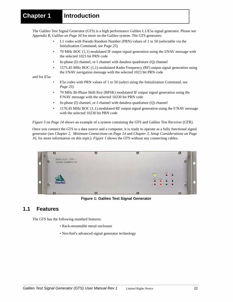
Once you connect the GTS to a data source and a computer, it is ready to operate as a fully functional signal generator (see Chapter 2, Minimum Connections on Page 14 and Chapter 3, Setup Considerations on Page 16, for more information on this topic). Figure 1 shows the GTS without any connecting cables.
Figure 1: Galileo Test Signal Generator
1.1 Features
The GTS has the following standard features:
• Rack-mountable metal enclosure
• NovAtel's advanced signal generator technology
Galileo Test Signal Generator (GTS) User Manual Rev 1 Limited Rights Notice 11

Introduction
1.2 Accessories and OptionsThe GTS can be used with the following accessories:
• Power cable to connect the GTS to a +100 to +240 V AC power source• Navigation data generator• Optional coaxial cables for the TNC and BNC connectors on the GTS• Optional GTR
Should you need to order an accessory or a replacement part, contact NovAtel.
1.3 Functional Overview
The signal generator is comprised of two independent L1 and E5a generators. These generators control the frequency and phase of the L1 and E5a code and carrier, and generate two independent L1 and E5a 70 MHz IF signals. The signal generator provides two loopback signals. These RF signals will be upconverted replicas of the 70 MHz L1 and E5a outputs. The 70 MHz L1 is upconverted to the Galileo L1 frequency of 1575.42 MHz and the 70 MHz E5a is upconverted to the Galileo E5a frequency of 1176.45 MHz.
The two L1 and E5a generators are housed within a common chassis. Each signal generator:
1. Accepts raw Galileo message symbols at a rate of one message packet per second (L1) or one message packet per 10s (E5a)
2. FEC Encodes the data
3. Block interleaves the data
4. Adds synchronization bits to the data
5. Generates and applies the specified PRN encoding to the data
6. Modulates the resulting encoding on to an in-phase ‘I’ channel carrier signal
7. Modulates the resulting encoding on to a quadraphase ‘Q’ channel carrier signal
8. Generates the accompanying ‘Q’ channel signal and adds it to the ‘I’ channel
Each of these sections are discussed in further detail in the following sections. Figure 2 on Page 13 shows the interfaces of the GTS.
12 Galileo Test Signal Generator (GTS) User Manual Rev 1 Limited Rights Notice

Introduction
Figure 2: Interface Block Diagram
After a cold start or after a power reset, the GTS performs an IBIT memory self-test.
Provided a 1PPS reference source is made available to the GTS, it can receive Navigation messages from the Navigation Data Generator within 2 minutes of powering up.
L5 Signal Generator
L1 Signal Generator
RS485
RS232
RS 485
RS232
Comparator Message Processor (CMP)
Interface
Comparator Message Processor (CMP)
Interface
WAAS Message Processor ( WMP) Control Interface
WAAS Message Processor ( WMP) Control Interface
L5 RF Output
L2 RF Output
70 MHz Output
70 MHz Output
From Receiver
10 MHz Input
10 MHz Output
Power
10 MHz Output
1 PPS
Code 1 PPS Output
Code 1 PPS Output
1PPS
Navigation Data Generation Interface
Message Control Interface
Navigation Data Generation Interface
Message Control Interface L1
E5a
E5a
Galileo Test Signal Generator (GTS) User Manual Rev 1 Limited Rights Notice 13
Chapter 2 Minimum Connections
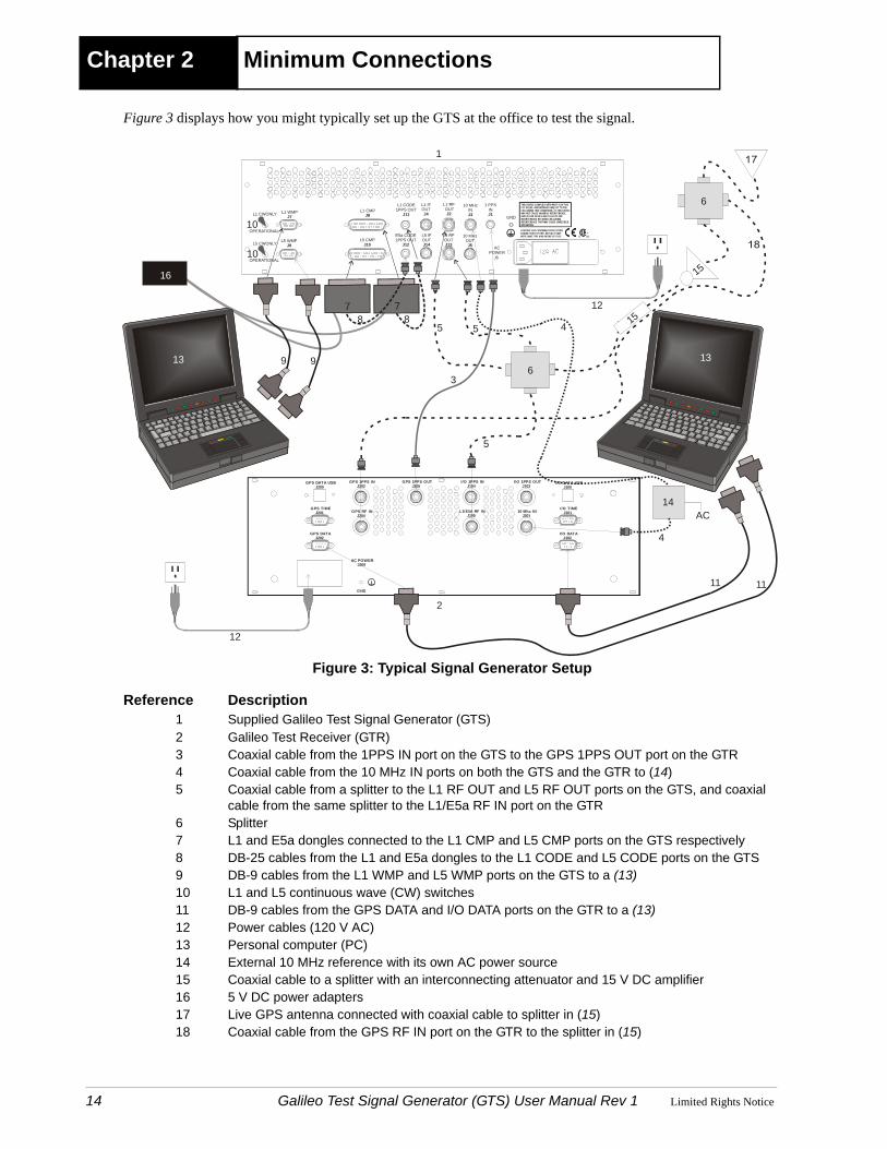
Figure 3 displays how you might typically set up the GTS at the office to test the signal.
Figure 3: Typical Signal Generator Setup
Reference Description1 Supplied Galileo Test Signal Generator (GTS)2 Galileo Test Receiver (GTR)3 Coaxial cable from the 1PPS IN port on the GTS to the GPS 1PPS OUT port on the GTR4 Coaxial cable from the 10 MHz IN ports on both the GTS and the GTR to (14)5 Coaxial cable from a splitter to the L1 RF OUT and L5 RF OUT ports on the GTS, and coaxial
cable from the same splitter to the L1/E5a RF IN port on the GTR6 Splitter7 L1 and E5a dongles connected to the L1 CMP and L5 CMP ports on the GTS respectively8 DB-25 cables from the L1 and E5a dongles to the L1 CODE and L5 CODE ports on the GTS9 DB-9 cables from the L1 WMP and L5 WMP ports on the GTS to a (13)10 L1 and L5 continuous wave (CW) switches11 DB-9 cables from the GPS DATA and I/O DATA ports on the GTR to a (13)12 Power cables (120 V AC)13 Personal computer (PC)14 External 10 MHz reference with its own AC power source15 Coaxial cable to a splitter with an interconnecting attenuator and 15 V DC amplifier16 5 V DC power adapters17 Live GPS antenna connected with coaxial cable to splitter in (15)18 Coaxial cable from the GPS RF IN port on the GTR to the splitter in (15)
10 Mhz INJ301
AC POWERJ300
GPS DATA USBJ200
GPS 1PPS INJ203
GPS DATAJ202
I/O 1PPS INJ104
L1/E5A RF INJ105
GPS 1PPS OUTJ205
I/O 1PPS OUTJ103
GPS RF INJ204
GPS TIMEJ201
I/O DATAJ102
I/O TIMEJ101
I/O DATA USBJ100
GND
L1 CWONLY L1 WMPJ7
L1 CMPJ8
10 MHzINJ3
1 PPSINJ1
GND
L5 CWONLY L5 WMPJ9
L5 CMPJ10
E5a CODE1PPS OUT
J12
L5 IFOUTJ14
L5 RF OUTJ13
1
2
3
45
6
78 8
5
99
10
10
11
1313
12
10 MHzOUTJ5
L1 CODE1PPS OUT
J11
L1 IFOUTJ4
L1 RF OUT
J2
14
ACPOWER
J6
CAUTION: FOR CONTINUED PROTECTIONAGAINST RISK OF FIRE, REPLACE ONLYWITH SAME TYPE AND RATING OF FUSE.
THIS DEVICE COMPLIES WITH PART 15 OF THEFCC RULES. OPERATION IS SUBJECT TO THEFOLLOWING TWO CONDITIONS: (1) THIS DEVICEMAY NOT CAUSE HARMFUL INTERFERENCE, AND (2) THIS DEVICE MUST ACCEPT ANYINTERFERENCE RECEIVED, INCLUDINGINTERFERENCE THAT MAY CAUSE UNDESIREDOPERATION.
7
16
OPERATIONAL
OPERATIONAL
AC
12
4
11
5
15
15
6
14 Galileo Test Signal Generator (GTS) User Manual Rev 1 Limited Rights Notice
Minimum Connections
A typical configuration would result from the following steps (see also Figure 3):
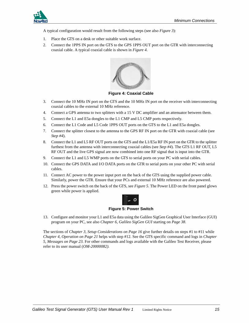
1. Place the GTS on a desk or other suitable work surface.2. Connect the 1PPS IN port on the GTS to the GPS 1PPS OUT port on the GTR with interconnecting
coaxial cable. A typical coaxial cable is shown in Figure 4.
Figure 4: Coaxial Cable
3. Connect the 10 MHz IN port on the GTS and the 10 MHz IN port on the receiver with interconnecting coaxial cables to the external 10 MHz reference.
4. Connect a GPS antenna to two splitters with a 15 V DC amplifier and an attenuator between them.5. Connect the L1 and E5a dongles to the L1 CMP and L5 CMP ports respectively.6. Connect the L1 Code and L5 Code 1PPS OUT ports on the GTS to the L1 and E5a dongles.7. Connect the splitter closest to the antenna to the GPS RF IN port on the GTR with coaxial cable (see
Step #4).8. Connect the L1 and L5 RF OUT ports on the GTS and the L1/E5a RF IN port on the GTR to the splitter
furthest from the antenna with interconnecting coaxial cables (see Step #4). The GTS L1 RF OUT, L5 RF OUT and the live GPS signal are now combined into one RF signal that is input into the GTR.
9. Connect the L1 and L5 WMP ports on the GTS to serial ports on your PC with serial cables.10. Connect the GPS DATA and I/O DATA ports on the GTR to serial ports on your other PC with serial
cables.11. Connect AC power to the power input port on the back of the GTS using the supplied power cable.
Similarly, power the GTR. Ensure that your PCs and external 10 MHz reference are also powered.12. Press the power switch on the back of the GTS, see Figure 5. The Power LED on the front panel glows
green while power is applied.
Figure 5: Power Switch
13. Configure and monitor your L1 and E5a data using the Galileo SigGen Graphical User Interface (GUI) program on your PC, see also Chapter 6, Galileo SigGen GUI starting on Page 38.
The sections of Chapter 3, Setup Considerations on Page 16 give further details on steps #1 to #11 while Chapter 4, Operation on Page 21 helps with step #12. See the GTS specific command and logs in Chapter 5, Messages on Page 23. For other commands and logs available with the Galileo Test Receiver, please refer to its user manual (OM-20000082).
Galileo Test Signal Generator (GTS) User Manual Rev 1 Limited Rights Notice 15
Chapter 3 Setup Considerations
The GTS is a device that is intended for use in dry stable environments. It is available with the following NovAtel accessories and options:
• Galileo Test Receiver• Coaxial cable to connect the GTS to the GTR• Supplied power cable• Navigation Data Generators• Galileo SigGen GUI
3.1 Front Panel Functionality
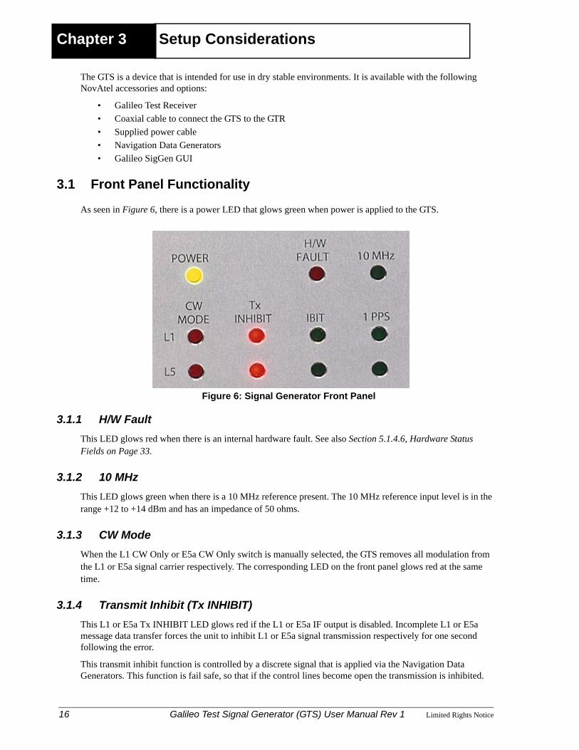
As seen in Figure 6, there is a power LED that glows green when power is applied to the GTS.
Figure 6: Signal Generator Front Panel
3.1.1 H/W FaultThis LED glows red when there is an internal hardware fault. See also Section 5.1.4.6, Hardware Status Fields on Page 33.
3.1.2 10 MHzThis LED glows green when there is a 10 MHz reference present. The 10 MHz reference input level is in the range +12 to +14 dBm and has an impedance of 50 ohms.
3.1.3 CW ModeWhen the L1 CW Only or E5a CW Only switch is manually selected, the GTS removes all modulation from the L1 or E5a signal carrier respectively. The corresponding LED on the front panel glows red at the same time.
3.1.4 Transmit Inhibit (Tx INHIBIT)This L1 or E5a Tx INHIBIT LED glows red if the L1 or E5a IF output is disabled. Incomplete L1 or E5a message data transfer forces the unit to inhibit L1 or E5a signal transmission respectively for one second following the error.
This transmit inhibit function is controlled by a discrete signal that is applied via the Navigation Data Generators. This function is fail safe, so that if the control lines become open the transmission is inhibited.
16 Galileo Test Signal Generator (GTS) User Manual Rev 1 Limited Rights Notice
Setup Considerations
3.1.5 Initiated Built in Test (IBIT)IBIT is performed at power-up or upon a hardware reset. IBIT includes ROM and RAM testing. The front panel specifies whether the L1 or E5a IBIT passed or failed. A green LED signifies an IBIT pass and an unlit LED signifies an IBIT failure.
3.1.6 1PPSThe 1PPS LEDs cycle at a 1 Hz rate to indicate the presence of a 1PPS output signal.
3.2 Rear Panel Functionality
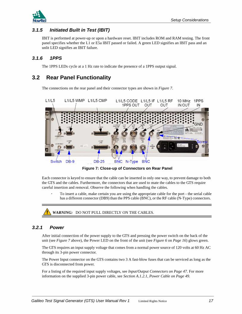
The connections on the rear panel and their connector types are shown in Figure 7.
Figure 7: Close-up of Connectors on Rear Panel
Each connector is keyed to ensure that the cable can be inserted in only one way, to prevent damage to both the GTS and the cables. Furthermore, the connectors that are used to mate the cables to the GTS require careful insertion and removal. Observe the following when handling the cables.
· To insert a cable, make certain you are using the appropriate cable for the port - the serial cablehas a different connector (DB9) than the PPS cable (BNC), or the RF cable (N-Type) connectors.
WARNING: DO NOT PULL DIRECTLY ON THE CABLES.
3.2.1 PowerAfter initial connection of the power supply to the GTS and pressing the power switch on the back of the unit (see Figure 7 above), the Power LED on the front of the unit (see Figure 6 on Page 16) glows green.
The GTS requires an input supply voltage that comes from a normal power source of 120 volts at 60 Hz AC through its 3-pin power connector.
The Power Input connector on the GTS contains two 3 A fast-blow fuses that can be serviced as long as the GTS is disconnected from power.
For a listing of the required input supply voltages, see Input/Output Connectors on Page 47. For more information on the supplied 3-pin power cable, see Section A.1.2.1, Power Cable on Page 49.
GPS TIME GPS DATA GPS DATA IPPS IN RF IN 1PPS OUT I/O 1PPS IN L1/E5A RF IN
GND
Switch DB-9 SCREW BNC USB
I/O1PPOUT
10 MHzIN
I/ODATI/OTIM
I/ODAT
Galileo Test Signal Generator (GTS) User Manual Rev 1 Limited Rights Notice 17

Setup Considerations
3.2.2 CW SwitchThe GTS provides a L1 CW and a E5a CW switch which removes all modulation from the L1 IF and RF or E5a IF and RF carriers respectively.
3.2.3 Navigation Data GeneratorThe GTS is supplied with two Navigation Data Generators for testing purposes. These dongles, see Figure 8 below, are programmed with test Galileo I/NAV and F/NAV messages that are modulated onto the L1 and E5a signals. Figure 8 also shows the 120 V AC power adapter that comes with each one.
Figure 8: Navigation Data Generator (left) and Power Adapter (right)
Each Navigation Data Generator comes with:
1. A 120 V AC power supply adapter2. An RS-485 interface with the GTS3. A Joint Test Action Group (JTAG) programming interface4. A 1-PPS input signal (from the GTS)
The GTS must be connected to the Navigation Data Generators (as shown in Figure 3 on Page 14) in order to transmit Galileo signals.
The Navigation Data Generator has been programmed with a repeating sequence of satellite frame data messages.
Navigation Data Generators can be re-programmed through a JTAG interface.
3.2.4 Navigation Data Generator and Message ProcessorEach GTS has independent command and status interfaces, and communicates over this interface with a host computer (Message Processor - MP). Similarly, the message interface for each GTS is independent, and communicates with a message generator (the Navigation Data Generator).
The GTS is capable of L1 or E5a communications via two ports, L1 WMP and L5 WMP respectively.
3.2.5 Code PPS OutputThe L1 and L5 Code PPS Out ports allow synchronization of an external Navigation Data Generator with the modulated L1 or E5a signal available respectively.
3.2.6 1PPS UpdateThe 1PPS update level is an active low pulse with TTL levels and an impedance of 3.4 KΩ. It is also factory-configurable to 50 Ω.
18 Galileo Test Signal Generator (GTS) User Manual Rev 1 Limited Rights Notice

Setup Considerations
The pulse width of the 1PPS update is 200 ms nominally with a repetition rate of 1PPS. The high to low transition is the reference edge. The high to low transition time is 5 ns or less. The high to low transition jitter with respect to the 10 MHz is 1 ns or less.
For further information on the electrical specifications or connector type for the 1PPS IN port, please see Input/Output Connectors on Page 47.
3.2.7 10 MHz In and 10 MHz OutThere are two reference signal BNC connectors on the back of the GTS for 10 MHz In and 10 MHz Out.
The default oscillator for the GTS is the internal OCXO. If you prefer you can provide your own external oscillator through the 10 MHz In connector. The GTS uses the 10 MHz input when detected. The GTS accepts a 10 MHz reference with the phase noise characteristic shown in Table 1 below.
Table 1: 10 MHz Reference Phase Noise
The 10 MHz output provides a high-stability reference signal. It permits the synchronization of other equipment operating at this frequency. The 10 MHz output is buffered from the current system reference signal. These may be the internal OCXO or an external 10 MHz input. Its output amplitude is in the range 0 to +6 dBm and its output impedance is 50 ohms.
For further information on the signals or connector type for the 10 MHz In and 10 MHz Out ports, please see Input/Output Connectors on Page 47.
3.2.8 RF OutThe L1 and E5a RF Out connectors provides Radio Frequency (RF) signals from the GTS. It is normally used to provide the L1 and E5a signals to a NovAtel Galileo Test Receiver via coaxial cable.
The GTS contains RF circuits to modulate and convert the digital In-Phase and Quadrature (I and Q) data streams to an RF signal spectrum.
The level of the unmodulated L1 RF Out of the GTS is in the range -100 dBm ± 1.5 dB with an RF output frequency of 1575.42 MHz. The E5a RF Out is in the range -100 dBm ± 1.5 dB with a RF output frequency of 1176.45 MHz.
The GTS L1 RF output is BOC (1,1) modulated at a 1.023 MHz rate. The E5a RF output is at 10.23 MHz. The RF output modulator phase imbalance is within ±3 degrees.
For further information on the signals or connector type for the RF Out connectors, please see Input/Output Connectors on Page 47.
3.2.9 IF OutThe L1 and E5a IF Out connectors provide Intermediate Frequency (IF) signals from the GTS. It is normally used to provide L1 and E5a signals that are uplinked to the GEO satellite.
The signal amplitude is within the range -20 dBm ± 1.5 dB for any specified I/Q configuration. The signal amplitude is stable to within 0.7 dB at ambient temperature and within 1.4 dB over the operating temperature range.
The factory configurable L1 signal (2, 4 or 22 MHz) is filtered by IF filters having the characteristics described in Table 2 on Page 20.
Offset from Carrier Phase Noise (<)1 Hz -108 dBc/Hz10 Hz -134 dBc/Hz
100 Hz -144 dBc/Hz1000 Hz -150 dBc/Hz
Galileo Test Signal Generator (GTS) User Manual Rev 1 Limited Rights Notice 19

Setup Considerations
Table 2: L1 IF Bandwidth Requirements
The IF output provides the phase noise characteristic shown in Table 3.
Table 3: IF Output Phase Noise
The L1 CW Only switch forces the unit to remove all modulation from the signal carrier (with I and Q signals both forced to zero).
Disabling of the L1 output signal from the GTS occurs under specific operating conditions identified in Section 5.2, Error Handling on Page 37.
The E5a signal is filtered with a 22 MHz IF filter having the characteristics described in Table 4.
Table 4: E5a IF Bandwidth Requirements
The output impedance for L1 and E5a is 50 Ohms.
Nominal Bandwidth 3 dB Bandwidth 20 dB Bandwidth 40 dB Bandwidth2 MHz > 2 MHz ± 1.5 MHz typical < 3.6 MHz4 MHz > 4 MHz ± 2.6 MHz typical < 6.0 MHz22 MHz > 22 MHz ± 12.5 MHz typical < 28 MHz
Offset from Carrier Phase Noise (<)1 Hz -65 dBc/Hz
10 Hz -85 dBc/Hz100 Hz -90 dBc/Hz1 KHz -95 dBc/Hz
10 KHz -100 dBc/Hz100 KHz -108 dBc/Hz
Nominal Bandwidth 3 dB Bandwidth 20 dB Bandwidth 40 dB Bandwidth22 MHz > 22 MHz ± 12.5 MHz typical < 28 MHz
20 Galileo Test Signal Generator (GTS) User Manual Rev 1 Limited Rights Notice

Chapter 4 OperationBefore operating the GTS for the first time, ensure that you have followed the installation instructions of Chapter 2, Minimum Connections on Page 14 and Chapter 3, Setup Considerations on Page 16. The following instructions are based on a configuration such as that shown in Figure 3, Typical Signal Generator Setup on Page 14. It is assumed that a personal computer is used during the initial operation and testing for greater ease and versatility.
4.1 Communications with the GTS
Communication with the GTS is straightforward, and consists of issuing commands through the communication ports from an external serial communications device. This could be either a terminal or an IBM-compatible PC that is directly connected to the GTS serial port using an extension cable. For information about commands and logs that are useful for basic operation of the GTS, please see Chapter 5, Messages on Page 23.
4.1.1 Serial Port Default SettingsThe GTS communicates with your PC or terminal via the communication ports. For communication to occur, both the GTS and the operator interface have to be configured properly. The GTS data ports’ settings are as follows:
• 19200 bps, odd parity, 8 data bits, 1 stop bit, cts/rts handshaking, echo off
4.1.2 Communicating Using a Remote TerminalOne method of communicating with the GTS is through a remote terminal. The GTS allows proper RS232 interface with your data terminal. To communicate with the terminal, the GTS requires the RX, TX, and GND lines to be used. Ensure that the terminal’s communications set-up matches the GTS’s RS232 protocol.
4.1.3 Communicating Using a Personal ComputerAn IBM-compatible PC can be set up to emulate a remote terminal as well as provide the added flexibility of creating multiple-command batch files and data logging storage files. Any standard communications software package that emulates a terminal can be used to establish bidirectional communications with the GTS. No particular terminal type is assured. All data is sent as raw characters.
You can create command batch files using any text editor; these can then be directed to the data port that is connected to the GTS using a communications software package. This is discussed later in this chapter.
4.2 Message Control and Data Lines
The Message Interface provides the necessary control and data lines to allow downloading of data symbols from the Navigation Data Generator to the GTS. These lines are:
1. MSGRDY from Navigation Data Generator to GTS
2. MSGCLK from GTS to Navigation Data Generator
3. MSGDATA from Navigation Data Generator to GTS
After a compared message is stored in the Navigation Data Generator output buffer, the Navigation Data Generator sets the Message Ready flag to the GTS.
The Message Ready signal enables the GTS internal 1 MHz clock (period 1 ms) which is then returned to the Navigation Data Generator.
Galileo Test Signal Generator (GTS) User Manual Rev 1 Limited Rights Notice 21
Operation
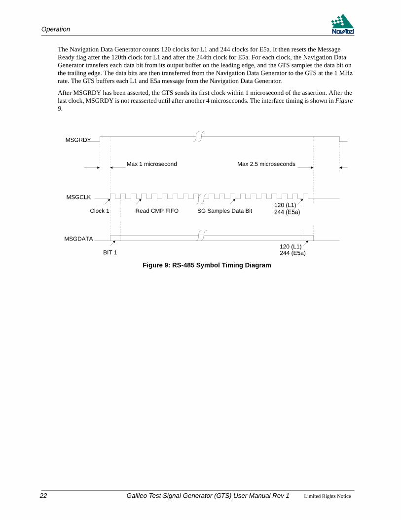
The Navigation Data Generator counts 120 clocks for L1 and 244 clocks for E5a. It then resets the Message Ready flag after the 120th clock for L1 and after the 244th clock for E5a. For each clock, the Navigation Data Generator transfers each data bit from its output buffer on the leading edge, and the GTS samples the data bit on the trailing edge. The data bits are then transferred from the Navigation Data Generator to the GTS at the 1 MHz rate. The GTS buffers each L1 and E5a message from the Navigation Data Generator.
After MSGRDY has been asserted, the GTS sends its first clock within 1 microsecond of the assertion. After the last clock, MSGRDY is not reasserted until after another 4 microseconds. The interface timing is shown in Figure 9.
Figure 9: RS-485 Symbol Timing Diagram
Max 1 microsecond
Read CMP FIFO SG Samples Data Bit Clock 500
BIT 1 BIT 500
Clock 1
Max 2.5 microseconds
MSGRDY
MSGCLK
MSGDATA
120 (L1)244 (E5a)
120 (L1))244 (E5a)
22 Galileo Test Signal Generator (GTS) User Manual Rev 1 Limited Rights Notice
Chapter 5 Messages
5.1 MP Message Structure
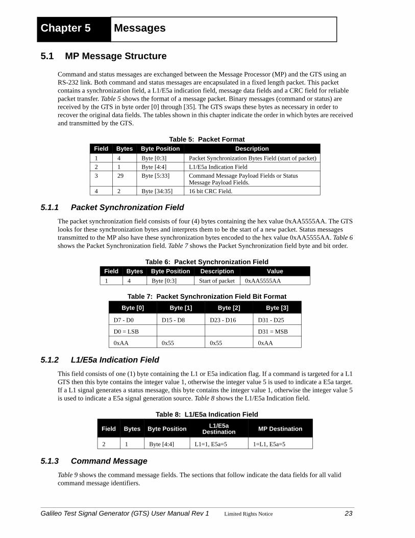
Command and status messages are exchanged between the Message Processor (MP) and the GTS using an RS-232 link. Both command and status messages are encapsulated in a fixed length packet. This packet contains a synchronization field, a L1/E5a indication field, message data fields and a CRC field for reliable packet transfer. Table 5 shows the format of a message packet. Binary messages (command or status) are received by the GTS in byte order [0] through [35]. The GTS swaps these bytes as necessary in order to recover the original data fields. The tables shown in this chapter indicate the order in which bytes are received and transmitted by the GTS.
Table 5: Packet Format
5.1.1 Packet Synchronization FieldThe packet synchronization field consists of four (4) bytes containing the hex value 0xAA5555AA. The GTS looks for these synchronization bytes and interprets them to be the start of a new packet. Status messages transmitted to the MP also have these synchronization bytes encoded to the hex value 0xAA5555AA. Table 6 shows the Packet Synchronization field. Table 7 shows the Packet Synchronization field byte and bit order.
Table 6: Packet Synchronization Field
Table 7: Packet Synchronization Field Bit Format
5.1.2 L1/E5a Indication FieldThis field consists of one (1) byte containing the L1 or E5a indication flag. If a command is targeted for a L1 GTS then this byte contains the integer value 1, otherwise the integer value 5 is used to indicate a E5a target. If a L1 signal generates a status message, this byte contains the integer value 1, otherwise the integer value 5 is used to indicate a E5a signal generation source. Table 8 shows the L1/E5a Indication field.
Table 8: L1/E5a Indication Field
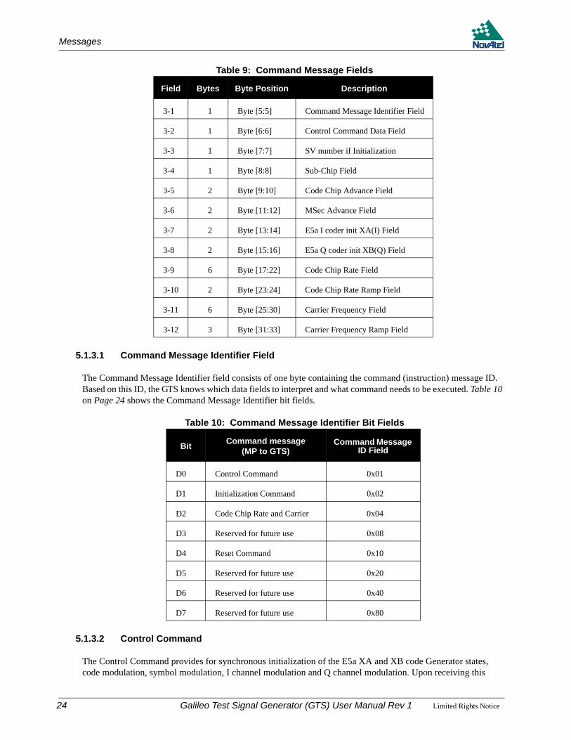
5.1.3 Command MessageTable 9 shows the command message fields. The sections that follow indicate the data fields for all valid command message identifiers.
Field Bytes Byte Position Description1 4 Byte [0:3] Packet Synchronization Bytes Field (start of packet) 2 1 Byte [4:4] L1/E5a Indication Field3 29 Byte [5:33] Command Message Payload Fields or Status
Message Payload Fields. 4 2 Byte [34:35] 16 bit CRC Field.
Field Bytes Byte Position Description Value1 4 Byte [0:3] Start of packet 0xAA5555AA
Byte [0] Byte [1] Byte [2] Byte [3]
D7 - D0 D15 - D8 D23 - D16 D31 - D25
D0 = LSB D31 = MSB
0xAA 0x55 0x55 0xAA
Field Bytes Byte Position L1/E5a Destination MP Destination
2 1 Byte [4:4] L1=1, E5a=5 1=L1, E5a=5
Galileo Test Signal Generator (GTS) User Manual Rev 1 Limited Rights Notice 23
Messages
Table 9: Command Message Fields
5.1.3.1 Command Message Identifier Field
The Command Message Identifier field consists of one byte containing the command (instruction) message ID. Based on this ID, the GTS knows which data fields to interpret and what command needs to be executed. Table 10 on Page 24 shows the Command Message Identifier bit fields.
Table 10: Command Message Identifier Bit Fields
5.1.3.2 Control Command
The Control Command provides for synchronous initialization of the E5a XA and XB code Generator states, code modulation, symbol modulation, I channel modulation and Q channel modulation. Upon receiving this
Field Bytes Byte Position Description
3-1 1 Byte [5:5] Command Message Identifier Field
3-2 1 Byte [6:6] Control Command Data Field
3-3 1 Byte [7:7] SV number if Initialization
3-4 1 Byte [8:8] Sub-Chip Field
3-5 2 Byte [9:10] Code Chip Advance Field
3-6 2 Byte [11:12] MSec Advance Field
3-7 2 Byte [13:14] E5a I coder init XA(I) Field
3-8 2 Byte [15:16] E5a Q coder init XB(Q) Field
3-9 6 Byte [17:22] Code Chip Rate Field
3-10 2 Byte [23:24] Code Chip Rate Ramp Field
3-11 6 Byte [25:30] Carrier Frequency Field
3-12 3 Byte [31:33] Carrier Frequency Ramp Field
Bit Command message (MP to GTS)
Command Message ID Field
D0 Control Command 0x01
D1 Initialization Command 0x02
D2 Code Chip Rate and Carrier 0x04
D3 Reserved for future use 0x08
D4 Reset Command 0x10
D5 Reserved for future use 0x20
D6 Reserved for future use 0x40
D7 Reserved for future use 0x80
24 Galileo Test Signal Generator (GTS) User Manual Rev 1 Limited Rights Notice
Messages
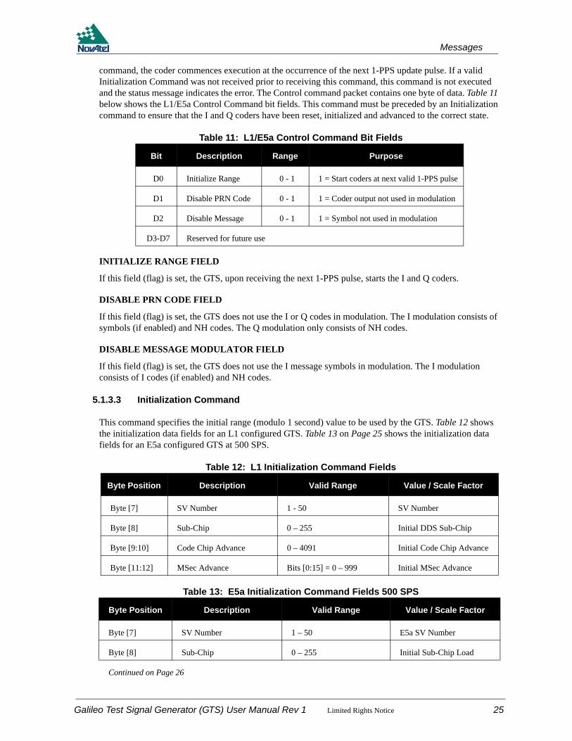
command, the coder commences execution at the occurrence of the next 1-PPS update pulse. If a valid Initialization Command was not received prior to receiving this command, this command is not executed and the status message indicates the error. The Control command packet contains one byte of data. Table 11 below shows the L1/E5a Control Command bit fields. This command must be preceded by an Initialization command to ensure that the I and Q coders have been reset, initialized and advanced to the correct state.
Table 11: L1/E5a Control Command Bit Fields
INITIALIZE RANGE FIELD
If this field (flag) is set, the GTS, upon receiving the next 1-PPS pulse, starts the I and Q coders.
DISABLE PRN CODE FIELD
If this field (flag) is set, the GTS does not use the I or Q codes in modulation. The I modulation consists of symbols (if enabled) and NH codes. The Q modulation only consists of NH codes.
DISABLE MESSAGE MODULATOR FIELD
If this field (flag) is set, the GTS does not use the I message symbols in modulation. The I modulation consists of I codes (if enabled) and NH codes.
5.1.3.3 Initialization Command
This command specifies the initial range (modulo 1 second) value to be used by the GTS. Table 12 shows the initialization data fields for an L1 configured GTS. Table 13 on Page 25 shows the initialization data fields for an E5a configured GTS at 500 SPS.
Table 12: L1 Initialization Command Fields
Table 13: E5a Initialization Command Fields 500 SPS
Bit Description Range Purpose
D0 Initialize Range 0 - 1 1 = Start coders at next valid 1-PPS pulse
D1 Disable PRN Code 0 - 1 1 = Coder output not used in modulation
D2 Disable Message 0 - 1 1 = Symbol not used in modulation
D3-D7 Reserved for future use
Byte Position Description Valid Range Value / Scale Factor
Byte [7] SV Number 1 - 50 SV Number
Byte [8] Sub-Chip 0 – 255 Initial DDS Sub-Chip
Byte [9:10] Code Chip Advance 0 – 4091 Initial Code Chip Advance
Byte [11:12] MSec Advance Bits [0:15] = 0 – 999 Initial MSec Advance
Byte Position Description Valid Range Value / Scale Factor
Byte [7] SV Number 1 – 50 E5a SV Number
Byte [8] Sub-Chip 0 – 255 Initial Sub-Chip Load
Continued on Page 26
Galileo Test Signal Generator (GTS) User Manual Rev 1 Limited Rights Notice 25

Messages
SV NUMBER FIELD
This value specifies the PRN to transmit. For L1, the 4092 bit PRN sequence for the specified PRN is loaded into the FPGA. For E5a, the 100-bit secondary code sequence for the pilot-channel (Q Channel) is loaded into the FPGA for the specified PRN.
SUB-CHIP FIELD
This value specifies the initial sub-chip phase to be loaded into the Code DDS in increments of 1/256 code chip.
CODE CHIP ADVANCE FIELD
This value specifies the initial code chip advance from zero chip count.
MSEC ADVANCE FIELD
This value specifies the initial msec epoch advance from zero msec count.
E5A I CODER INIT XB(I) FIELD
This field contains the initial state (14 bits) of the E5a I Channel XB(I) code generator. See Table 14 for the I channel XB(I) coder initialization field bit format.
Table 14: E5a I Channel XB(I) Coder Initialization Field
E5A Q CODER INIT XB(Q) FIELD
This field contains the initial state (14 bits) of the E5a Q Channel XB(Q) code generator. If this field is set to zero, the Q Channel XB(Q) coder does not participate in modulation. Table 15 shows the byte and bit ordering for the Q channel XB(Q) coder initialization field.
Table 15: E5a Q Channel XB(Q) Coder Initialization Field
Byte Position Description Valid Range Value / Scale Factor
Byte [9:10] Code Chip Advance 0 – 10229 Initial Code Chip Advance
Byte [11:12] MSec Advance Bits [0:15] = 0 – 999 Initial MSec Advance
Byte [13:14] I coder init XB(I).Byte[13] = init bits 0-7Byte[14] = init bits 8-12
XA2 I channel coder initialization value at zero chip count.
Byte [15:16] Q coder init XB(Q).Byte[15] = init bits 0-7Byte[16] = init bits 8-12
XB2 Q channel coder initialization value at zero chip count.
LS Byte [13] MS Byte [14]
D7 D6 D5 D4 D3 D2 D1 D0 - - D13 D12 D11 D10 D9 D8
LSB MSB
XBI(7) (6) (5) (4) (3) (2) (1) XBI(0) - - XBI(13) 12 11 10 9 XBI(8)
LS Byte [15] MS Byte [16]
D7 D6 D5 D4 D3 D2 D1 D0 - - D13 D12 D11 D10 D9 D8
LSB MSB
XBQ(7) (6) (5) (4) (3) (2) (1) XBQ(0) - - XBQ(13) 12 11 10 9 XBQ(8)
26 Galileo Test Signal Generator (GTS) User Manual Rev 1 Limited Rights Notice

Messages
5.1.3.4 Code Chip Rate and Carrier Frequency Command
The Code Chip Rate and Carrier Frequency Command specifies in absolute terms, the new Code Chip Rate and Carrier Frequency (for either L1 or E5a) to be assigned at the next 1PPS update pulse. Table 16 shows all fields applicable to this command.
Table 16: L1/E5a Code Chip Rate and Carrier Frequency Command Fields
CODE CHIP RATE FIELD
The Code Chip Rate field specifies the absolute initial code clock frequency. Table x shows the byte and bit ordering for the Code Chip Rate field.
Table 17: Code Chip Rate Ramp Field
CARRIER FREQUENCY FIELD
The Carrier Frequency Command specifies in absolute terms, the new Carrier Frequency (for either L1 or E5a) to be assigned at the next 1PPS update pulse. See Table 18 for the Carrier Frequency field byte and bit order format.
Table 18: Carrier Frequency Field Bit Format
5.1.3.5 Reset Command
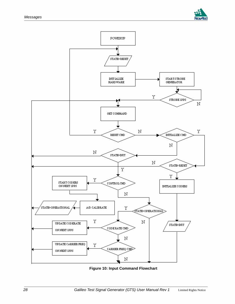
The Reset Command allows the GTS to be put into a reset state when operational. When this command is received, the GTS performs the actions as shown in Figure 10 on Page 28. There are no data fields associated with this command.
5.1.3.6 Watchdog Timer
The watchdog performs a GTS board reset if it is not serviced for 3 seconds due to a software failure. The software services the watchdog as frequently as possible to prevent the watchdog from resetting the digital board under normal operating conditions.
Byte Position Description Valid Range Scale Factor
Data Byte [17:22] Code Chip Rate 1.023 ±0.25/1540 Mcps (L1)10.23 ±0.25/115 Mcps (E5a)
LSB = 75 x 2-48 Mcps
Data Byte [23:24] Reserved
Data Byte [25:30] Carrier Frequency
70 ±0.25 MHz LSB = 300 x 2-48 MHz
Data Byte [31:33] Reserved
Byte [17] Byte [18] Byte [19] Byte [20] Byte [21] Byte [22]D7 - D0 D15 - D8 D23 - D16 D31 - D24 D39 - D32 D47 - D40D0 = LSB D47 = MSB
Byte [25]LS Byte Byte [26] Byte [27] Byte [28] Byte [29] Byte [30]
MS Byte
D7 – D0 D15 – D8 D23 – D16 D31 – D24 D39 – D32 D47 - D40
D0 = LSB D47 = MSB
Galileo Test Signal Generator (GTS) User Manual Rev 1 Limited Rights Notice 27
Messages
28
Figure 10: Input Command Flowchart
Galileo Test Signal Generator (GTS) User Manual Rev 1 Limited Rights Notice
Messages
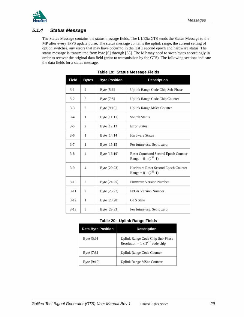
5.1.4 Status MessageThe Status Message contains the status message fields. The L1/E5a GTS sends the Status Message to the MP after every 1PPS update pulse. The status message contains the uplink range, the current setting of option switches, any errors that may have occurred in the last 1 second epoch and hardware status. The status message is transmitted from byte [0] through [33]. The MP may need to swap bytes accordingly in order to recover the original data field (prior to transmission by the GTS). The following sections indicate the data fields for a status message.
Table 19: Status Message Fields
Table 20: Uplink Range Fields
Field Bytes Byte Position Description
3-1 2 Byte [5:6] Uplink Range Code Chip Sub-Phase
3-2 2 Byte [7:8] Uplink Range Code Chip Counter
3-3 2 Byte [9:10] Uplink Range MSec Counter
3-4 1 Byte [11:11] Switch Status
3-5 2 Byte [12:13] Error Status
3-6 1 Byte [14:14] Hardware Status
3-7 1 Byte [15:15] For future use. Set to zero.
3-8 4 Byte [16:19] Reset Command Second Epoch CounterRange = 0 – (231-1)
3-9 4 Byte [20:23] Hardware Reset Second Epoch CounterRange = 0 – (231-1)
3-10 2 Byte [24:25] Firmware Version Number
3-11 2 Byte [26:27] FPGA Version Number
3-12 1 Byte [28:28] GTS State
3-13 5 Byte [29:33] For future use. Set to zero.
Data Byte Position Description
Byte [5:6] Uplink Range Code Chip Sub-Phase Resolution = 1 x 2-16 code chip
Byte [7:8] Uplink Range Code Counter
Byte [9:10] Uplink Range MSec Counter
Galileo Test Signal Generator (GTS) User Manual Rev 1 Limited Rights Notice 29

Messages
5.1.4.1 Uplink Range Code Chip Sub-Phase Field
This field contains the sub-phase of the code chip latched, within the current 1 ms epoch, upon detection of a 1PPS update pulse. Table 21 on Page 30 shows the Uplink Range Code Chip Sub-Phase field byte and bit order.
Table 21: Uplink Range Code Chip Sub-Phase Field
5.1.4.2 Uplink Range Code Chip Counter Field
This field contains the code count latched, within the current 1 ms epoch, upon detection of a 1PPS update pulse. Table 22 shows the Uplink Range Code Counter field byte and bit order.
Table 22: Uplink Range Code Chip Counter Field
5.1.4.3 Uplink Range MSec Counter Field
This field contains the msec count latched, within the current 1 ms epoch, upon detection of a 1PPS update pulse. Table 23 shows the Uplink Range MSec Counter field byte and bit order.
Table 23: Uplink Range MSec Counter Field
5.1.4.4 Switch Status Fields
The Switch Status field contains the current state of all GTS switches. The switch settings are polled when the Status Message is created at the start of the current 1 second epoch. Table 24 shows the Switch Status field byte and bit order. Table 25 on Page 31 shows the Switch Status bit fields.
Table 24: Switch Status Field
LS Byte [5] MS Byte [6]
D7 D6 D5 D4 D3 D2 D1 D0 D15 D14 D13 D12 D11 D10 D9 D8
LSB MSB
LS Byte [7] MS Byte [8]
D7 D6 D5 D4 D3 D2 D1 D0 D15 D14 D13 D12 D11 D10 D9 D8
LSB MSB
LS Byte [9] MS Byte [10]
D7 D6 D5 D4 D3 D2 D1 D0 D15 D14 D13 D12 D11 D10 D9 D8
LSB MSB
Byte [11]
D7 D6 D5 D4 D3 D2 D1 D0
MSB LSB
30 Galileo Test Signal Generator (GTS) User Manual Rev 1 Limited Rights Notice
Messages
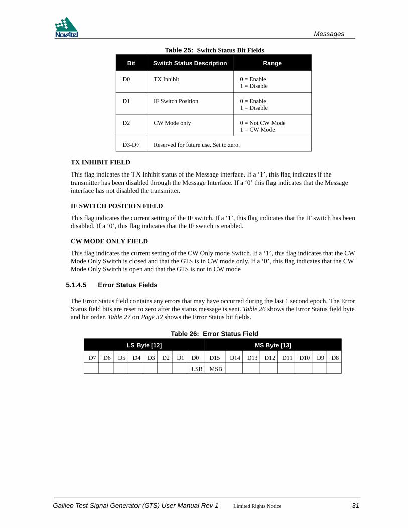
Table 25: Switch Status Bit Fields
TX INHIBIT FIELD
This flag indicates the TX Inhibit status of the Message interface. If a ‘1’, this flag indicates if the transmitter has been disabled through the Message Interface. If a ‘0’ this flag indicates that the Message interface has not disabled the transmitter.
IF SWITCH POSITION FIELD
This flag indicates the current setting of the IF switch. If a ‘1’, this flag indicates that the IF switch has been disabled. If a ‘0’, this flag indicates that the IF switch is enabled.
CW MODE ONLY FIELD
This flag indicates the current setting of the CW Only mode Switch. If a ‘1’, this flag indicates that the CW Mode Only Switch is closed and that the GTS is in CW mode only. If a ‘0’, this flag indicates that the CW Mode Only Switch is open and that the GTS is not in CW mode
5.1.4.5 Error Status Fields
The Error Status field contains any errors that may have occurred during the last 1 second epoch. The Error Status field bits are reset to zero after the status message is sent. Table 26 shows the Error Status field byte and bit order. Table 27 on Page 32 shows the Error Status bit fields.
Table 26: Error Status Field
Bit Switch Status Description Range
D0 TX Inhibit 0 = Enable1 = Disable
D1 IF Switch Position 0 = Enable1 = Disable
D2 CW Mode only 0 = Not CW Mode1 = CW Mode
D3-D7 Reserved for future use. Set to zero.
LS Byte [12] MS Byte [13]
D7 D6 D5 D4 D3 D2 D1 D0 D15 D14 D13 D12 D11 D10 D9 D8
LSB MSB
Galileo Test Signal Generator (GTS) User Manual Rev 1 Limited Rights Notice 31
Messages
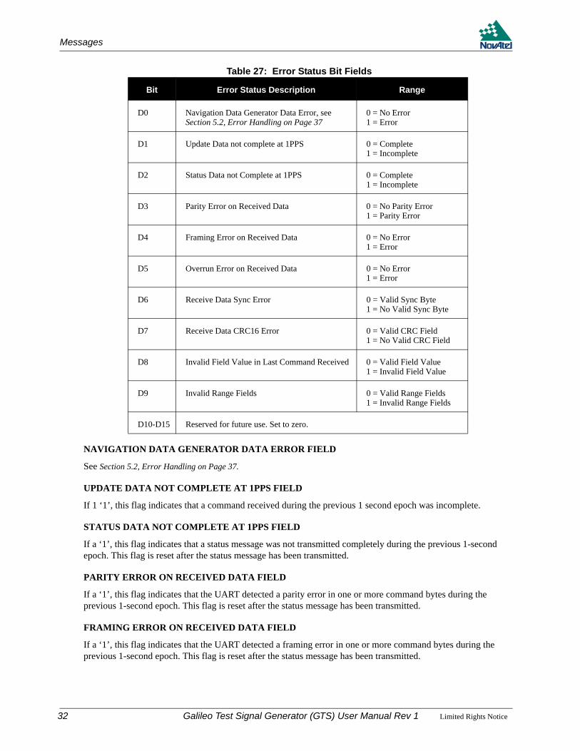
Table 27: Error Status Bit Fields
NAVIGATION DATA GENERATOR DATA ERROR FIELD
See Section 5.2, Error Handling on Page 37.
UPDATE DATA NOT COMPLETE AT 1PPS FIELD
If 1 ‘1’, this flag indicates that a command received during the previous 1 second epoch was incomplete.
STATUS DATA NOT COMPLETE AT 1PPS FIELD
If a ‘1’, this flag indicates that a status message was not transmitted completely during the previous 1-second epoch. This flag is reset after the status message has been transmitted.
PARITY ERROR ON RECEIVED DATA FIELD
If a ‘1’, this flag indicates that the UART detected a parity error in one or more command bytes during the previous 1-second epoch. This flag is reset after the status message has been transmitted.
FRAMING ERROR ON RECEIVED DATA FIELD
If a ‘1’, this flag indicates that the UART detected a framing error in one or more command bytes during the previous 1-second epoch. This flag is reset after the status message has been transmitted.
Bit Error Status Description Range
D0 Navigation Data Generator Data Error, see Section 5.2, Error Handling on Page 37
0 = No Error1 = Error
D1 Update Data not complete at 1PPS 0 = Complete1 = Incomplete
D2 Status Data not Complete at 1PPS 0 = Complete1 = Incomplete
D3 Parity Error on Received Data 0 = No Parity Error1 = Parity Error
D4 Framing Error on Received Data 0 = No Error1 = Error
D5 Overrun Error on Received Data 0 = No Error1 = Error
D6 Receive Data Sync Error 0 = Valid Sync Byte1 = No Valid Sync Byte
D7 Receive Data CRC16 Error 0 = Valid CRC Field1 = No Valid CRC Field
D8 Invalid Field Value in Last Command Received 0 = Valid Field Value1 = Invalid Field Value
D9 Invalid Range Fields 0 = Valid Range Fields1 = Invalid Range Fields
D10-D15 Reserved for future use. Set to zero.
32 Galileo Test Signal Generator (GTS) User Manual Rev 1 Limited Rights Notice

Messages
OVERRUN ERROR ON RECEIVED DATA FIELD
If a ‘1’, this flag indicates that the UART detected an overrun error in one or more command bytes during the previous 1-second epoch. This flag is reset after the status message has been transmitted.
RECEIVE DATA SYNC ERROR FIELD
If a ‘1’, this flag indicates that the GTS did not receive a valid sync byte in a command packet during the previous 1-second epoch. This flag is reset after the status message has been transmitted.
RECEIVE DATA CRC ERROR FIELD
If a ‘1’, this flag indicates that the GTS detected an invalid CRC field in a command packet during the previous 1-second epoch. This flag is reset after the status message has been transmitted.
INVALID FIELD VALUE FIELD
If a ‘1’, this flag indicates that the GTS detected an invalid field value in the last command received, during the previous 1-second epoch. This flag is reset after the status message has been transmitted.
INVALID RANGE FIELDS FIELD
If a ‘1’, this flag indicates that the range fields contained in this status message are invalid and should not be used.
5.1.4.6 Hardware Status Fields
The Hardware Status field contains the current state of the GTS hardware. The hardware is polled when the Status Message is created at the start of the current 1 second epoch. Table 28 shows the Hardware Status field bit order. Table 29 on Page 34 shows the Hardware Status bit fields.
Table 28: Hardware Status FieldByte [14]
D7 D6 D5 D4 D3 D2 D1 D0
MSB LSB
Galileo Test Signal Generator (GTS) User Manual Rev 1 Limited Rights Notice 33

Messages
Table 29: Hardware Status Bit Fields
10 MHZ PRESENT FIELD
This flag indicates if the 10 MHz clock signal is present. If a ‘1’, then the 10 MHz signal is present. If a ‘0’, then the 10 MHz signal is absent.
CLOCK CIRCUIT FAULT FIELD
This flag indicates if the clock circuit board is faulty. If a ‘1’, then the clock circuit board is faulty. If a ‘0’, then the clock circuit board is not faulty.
RF CIRCUIT FAULT FIELD
This flag indicates if the RF circuit board is faulty. If a ‘1’, then the RF circuit board is faulty. If a ‘0’, then the RF circuit board is not faulty.
GTS OPERATIONAL
This flag indicates if the GTS is operational and that Code Rate Commands and Carrier Frequency Commands are accepted. If this bit is set to ‘0’, Code Rate Commands and Carrier Frequency Commands are not applied. If this bit is set to ‘1’, the GTS is operational and Code Rate Commands and Carrier Frequency Commands are applied. This bit is only set to ‘0’ at power-up and after a Reset Command is received. It is set to ‘1’ after a Control Command is received and all internal calibrations have been performed.
REFERENCE 1PPS PRESENT FIELD
The flag indicates if the 1PPS reference is present. If this bit is set to ‘1’, the 1PPS signal is present. If this bit is set to ‘0’, the 1PPS signal is not present.
5.1.4.7 Reset Command Second Epoch Counter
This field contains the number of one second epochs counted since the last hardware reset occurred or since the last RESET command was received. The counter is started upon successful detection of an external 1PPS update pulse. The range of this field is 0 – (231-1). The MSB is set to zero to prevent false detection of packet SYNC header bytes. Table 30 on Page 35 shows the byte order and format for this field.
Bit Hardware Status Description Range
D0 Reference 10 MHz Present 0 = Not Present1 = Present
D1 Clock Circuit Fault 0 = No Fault1 = Fault
D2 RF Circuit Fault 0 = No Fault1 = Fault
D3 Reserved for future use
D4
D5
D6 GTS Operational 0 = Not Operational 1 = Operational
D7 Reference 1PPS present 0 = Not Present1 = Present
34 Galileo Test Signal Generator (GTS) User Manual Rev 1 Limited Rights Notice
Messages
Table 30: Reset Command Second Epoch Counter
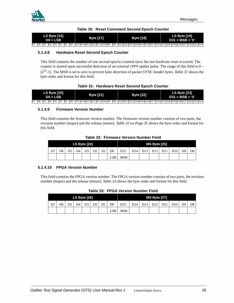
5.1.4.8 Hardware Reset Second Epoch Counter
This field contains the number of one second epochs counted since the last hardware reset occurred. The counter is started upon successful detection of an external 1PPS update pulse. The range of this field is 0 – (231-1). The MSB is set to zero to prevent false detection of packet SYNC header bytes. Table 31 shows the byte order and format for this field.
Table 31: Hardware Reset Second Epoch Counter
5.1.4.9 Firmware Version Number
This field contains the firmware version number. The firmware version number consists of two parts, the revision number (major) and the release (minor). Table 32 on Page 35 shows the byte order and format for this field.
Table 32: Firmware Version Number Field
5.1.4.10 FPGA Version Number
This field contains the FPGA version number. The FPGA version number consists of two parts, the revision number (major) and the release (minor). Table 33 shows the byte order and format for this field.
Table 33: FPGA Version Number Field
LS Byte [16]D0 = LSB Byte [17] Byte [18] LS Byte [19]
D31 = MSB = ‘0’D7 D6 D5 D4 D3 D2 D1 D0 D15 D14 D13 D12 D11 D10 D9 D8 D23 D22 D21 D20 D19 D18 D17 D16 D31 D30 D29 D28 D27 D26 D25 D24
LS Byte [20]D0 = LSB Byte [21] Byte [22] LS Byte [23]
D31 = MSB = ‘0’D7 D6 D5 D4 D3 D2 D1 D0 D15 D14 D13 D12 D11 D10 D9 D8 D23 D22 D21 D20 D19 D18 D17 D16 D31 D30 D29 D28 D27 D26 D25 D24
LS Byte [24] MS Byte [25]
D7 D6 D5 D4 D3 D2 D1 D0 D15 D14 D13 D12 D11 D10 D9 D8
LSB MSB
LS Byte [26] MS Byte [27]
D7 D6 D5 D4 D3 D2 D1 D0 D15 D14 D13 D12 D11 D10 D9 D8
LSB MSB
Galileo Test Signal Generator (GTS) User Manual Rev 1 Limited Rights Notice 35

Messages
5.1.4.11 GTS State
This field contains the state of the GTS during the previous one second epoch. Table 34 shows the byte order and format for this field. Table 35 on Page 36 shows the GTS state values.
Table 34: GTS State Field
Table 35: GTS State Value
5.1.5 CRC-16/CCITT Checksum FieldA CRC-16/CCITT Cyclic Redundancy Check field is used to validate the received message to a high degree of confidence that it was not corrupted during transmission. The sending system calculates the CRC-16 on all message bytes excluding the CRC data bytes, and appends it to the message. The receiving system calculates the CRC-16 on all message bytes received, excluding the CRC data bytes. The calculated CRC is compared with the received CRC. If the calculated CRC does not match the received CRC, the received message is declared as corrupted. A corrupted message is not used. Table 36 shows the CRC-16/CCITT field and Table 37 on Page 36 shows its bit format. The characteristics for the CRC-16/CCITT are shown in Table 38 on Page 37.
Table 36: CRC-16/CCITT Checksum Field
Table 37: CRC-16/CCITT Checksum Field
Byte [28]
D7 D6 D5 D4 D3 D2 D1 D0
MSB LSB
State Value Description0 Invalid State Error. This indicates a software error.1 RESET state2 INITIALIZED state3 CALIBRATION state4 OPERATIONAL state
Field Bytes Byte Position Description Range
4 2 Byte [34:35] CRC16 Checksum Hex 0000 – FFFF
LS Byte [34] MS Byte [35]
D7 D6 D5 D4 D3 D2 D1 D0 D15 D14 D13 D12 D11 D10 D9 D8
LSB MSB
36 Galileo Test Signal Generator (GTS) User Manual Rev 1 Limited Rights Notice

Messages
Table 38: CRC-16-CCITT Characteristics
5.2 Error Handling
Table 39 shows the GTS error conditions and their corresponding handling methods.
Table 39: Errors
Name CRC-16/CCITT
CRC Width 16 Bits
Polynomial 1021 = X16 + X12 + X5 + X0
Initial CRC Value 0xFFFF Hex
Input Bytes Reflected? NO
Output CRC Result Reflected? NO
Output XOR Value 0x0000
Single Bit Errors Detected 100%
Double Bit Errors Detected 100%
Odd Numbered Bit Errors Detected 100%
Burst Errors Shorter Than 16 Bits 100%
Burst Errors of Exactly 17 Bits 99.9968%
All Other Burst Errors 99.9984%
Error Description Handling Method Notes
Navigation Data Generator message truncated
I and Q set to zero and Transmitter disabled
Report status
Navigation Data Generator MSGRDY stuck high
I and Q set to zero and Transmitter disabled
Report status
Navigation Data Generator MSGRDY stuck low
I and Q set to zero and Transmitter disabled
Report status
MSGDATA not ready when needed I and Q set to zero and Transmitter disabled
Report status
Galileo Test Signal Generator (GTS) User Manual Rev 1 Limited Rights Notice 37
Chapter 6 Galileo SigGen GUI
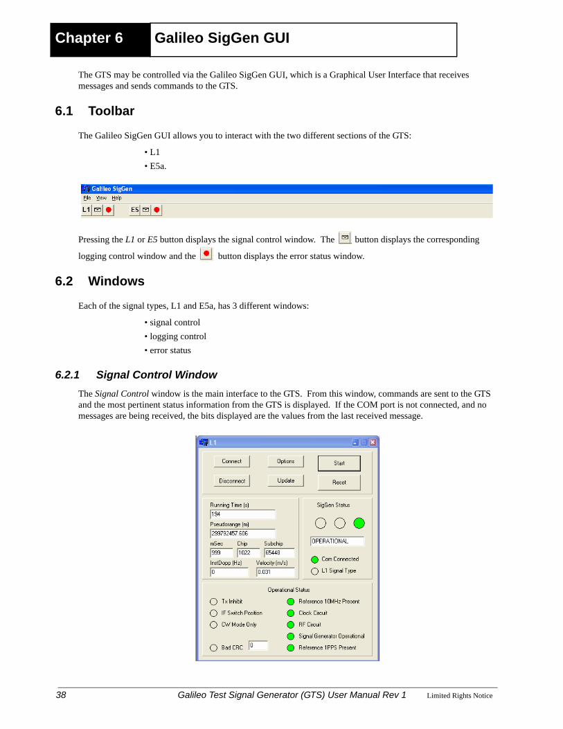
The GTS may be controlled via the Galileo SigGen GUI, which is a Graphical User Interface that receives messages and sends commands to the GTS.
6.1 Toolbar
The Galileo SigGen GUI allows you to interact with the two different sections of the GTS:
• L1 • E5a.
Pressing the L1 or E5 button displays the signal control window. The button displays the corresponding
logging control window and the button displays the error status window.
6.2 Windows
Each of the signal types, L1 and E5a, has 3 different windows:
• signal control• logging control• error status
6.2.1 Signal Control WindowThe Signal Control window is the main interface to the GTS. From this window, commands are sent to the GTS and the most pertinent status information from the GTS is displayed. If the COM port is not connected, and no messages are being received, the bits displayed are the values from the last received message.
38 Galileo Test Signal Generator (GTS) User Manual Rev 1 Limited Rights Notice
Galileo SigGen GUI
The middle left panel of the window displays the operational conditions of the GTS. The time from the last reset, the pseduorange (in metres, milliseconds, chips and subchips), the Instantaneous Doppler and the velocity.
The middle right panel of the window displays the status of the GTS. A green light indicates that the GTS is in operational mode, a yellow light indicates initialization/calibration/unknown state, and a red light indicates a reset state. An unknown state means that no message from the GTS has been received since the window was opened.
If the communications port is connected, a green LED is displayed beside Com Connected and a red LED is displayed when it is not connected. If the COM port is connected to the wrong signal (that is, the L1 window is actually connected to the E5a section of the GTS), a red LED flashes at a rate of 1 Hz next to L1 Signal Type.
The bottom panel of the window displays the operational status and is updated every second based on the received message from the GTS. The switch status bits are displayed on the left hand side and display a red LED when the corresponding bit is set to 1. If a message with a bad CRC is received, a red LED flashes once next to Bad CRC and a running total of the bad CRCs received is displayed. On the right hand side, are the hardware status bits where a green LED indicates a good or desired state and a red LED indicates a bad or undesired state.
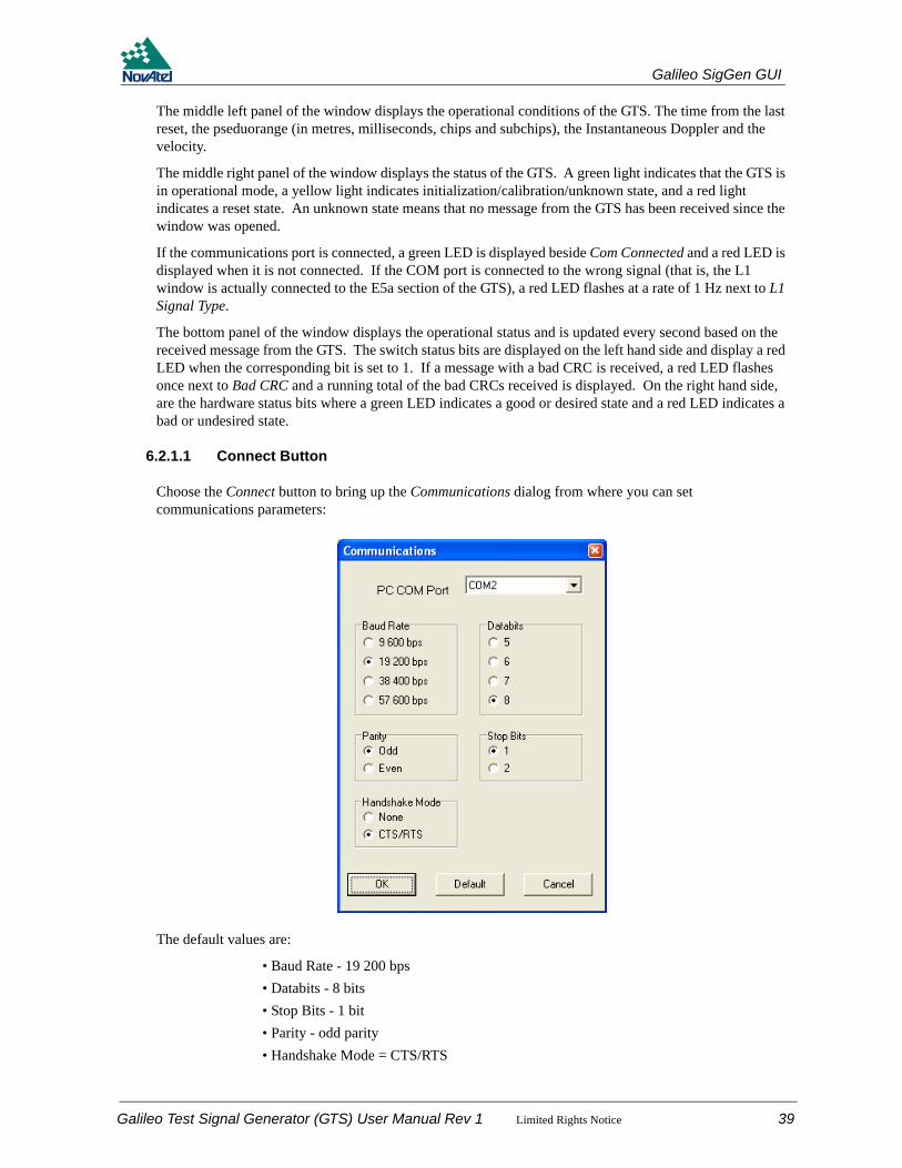
6.2.1.1 Connect Button
Choose the Connect button to bring up the Communications dialog from where you can set communications parameters:
The default values are:
• Baud Rate - 19 200 bps• Databits - 8 bits• Stop Bits - 1 bit• Parity - odd parity• Handshake Mode = CTS/RTS
Galileo Test Signal Generator (GTS) User Manual Rev 1 Limited Rights Notice 39

Galileo SigGen GUI
Click on the Default button to reset to the default parameters. Parameters are applied once you click on the OK button.
6.2.1.2 Disconnect button
Click on the Disconnect button to disconnect the current COM port. To reconnect, refer to Section 6.2.1.1, Connect Button on Page 39.
6.2.1.3 Options Button
Click on the Options button to bring up the Initialize/Control Commands dialog and options. The Options button can only be selected when the receiver is in a reset state. (A red light in the SigGen Status panel of the Signal Control window indicates a reset state, see also Section 6.2.1, Signal Control Window starting on Page 38.)
The default values are:
• PRN - 1
• Initial MilliSecond Advance - 0 ms
• Initial Code Chip Advance - 0 chips
• Initial Subchip Advance - 0 subchips
• Initialize range at next 1PPS - checked
• Disable PRN chip sequence in channel output - unchecked
• Disable message symbols in channel output - unchecked
Click on the Default button to reset to the default parameters. Parameters are not applied until you click on the OK button.
6.2.1.4 Update Button
The Update button allows the instantaneous Doppler of the signal to be modified with a value of 250 kHz in steps of 1 Hz using a sliding bar. The selected Doppler is displayed numerically in the text area above the sliding bar. The default Doppler value is 0 Hz.
40 Galileo Test Signal Generator (GTS) User Manual Rev 1 Limited Rights Notice

Galileo SigGen GUI
The Doppler is immediately applied once to the signal when you click on the OK button, and is maintained until the signal is reset or another Doppler is applied. This command is only applied if the GTS is in an operational state. (A green light in the SigGen Status panel of the Signal Control window indicates that the GTS is in operational mode, see also Section 6.2.1, Signal Control Window starting on Page 38.)
Click on the Default button to reset the Doppler to the default value. A new Doppler value is not applied until you click on the OK button.
6.2.1.5 Start Button
Click on the Start button to send the following commands to the GTS:
1. Reset2. Initialize Command (with the initialization parameters selected in the Initialize/Control Commands
dialog from the Options button)3. Control Command (with the control parameters selected in the Initialize/Control Commands dialog
from the Options button)
6.2.1.6 Reset Button
Click on the Reset button to send a reset command to the GTS.
6.2.2 Logging Control WindowThe logging control window displays the raw commands sent to the GTS and the raw messages sent by the GTS in hexadecimal format. Click on the Change File button to save these messages to a file. Select a file name and then check the Log button. The file name and directory is displayed in the text area to the right of the button. If there is a previously created file, it is overwritten. Check the Log button to save the commands and messages and append them to the current file.
6.2.3 Error Status WindowThe error status window displays the status bits reported in the error status bit field that is sent by the GTS
Galileo Test Signal Generator (GTS) User Manual Rev 1 Limited Rights Notice 41
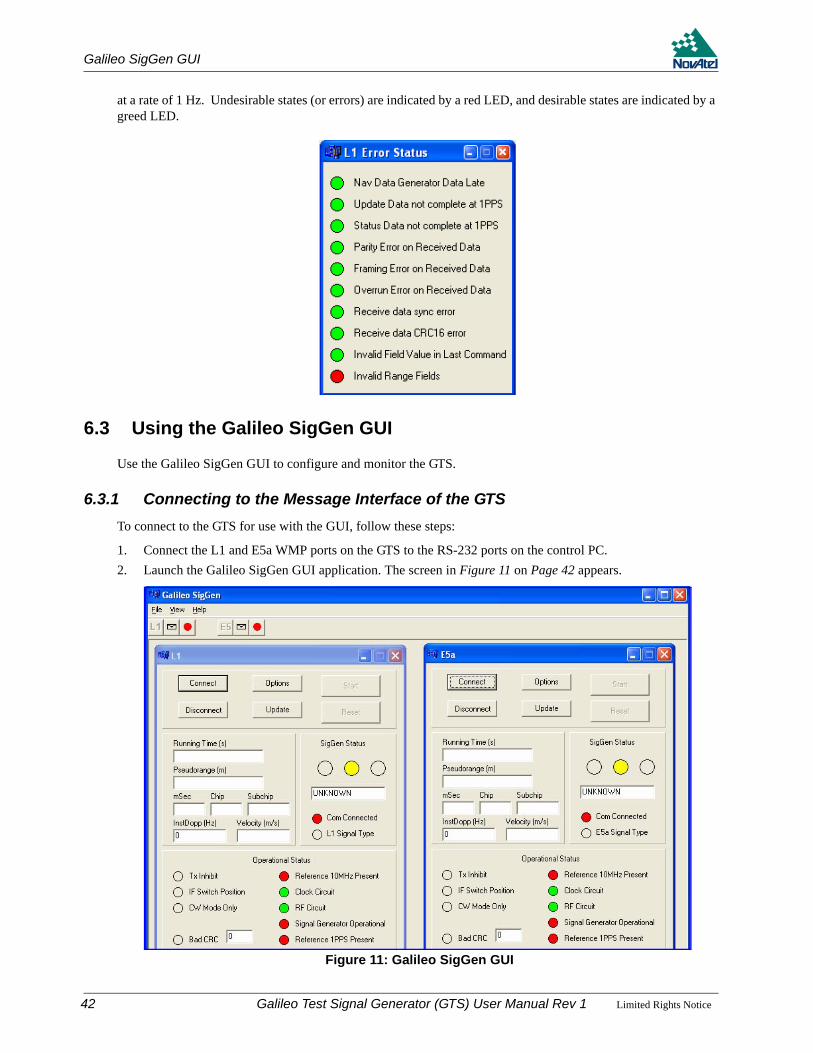
Galileo SigGen GUI
at a rate of 1 Hz. Undesirable states (or errors) are indicated by a red LED, and desirable states are indicated by a greed LED.
6.3 Using the Galileo SigGen GUI
Use the Galileo SigGen GUI to configure and monitor the GTS.
6.3.1 Connecting to the Message Interface of the GTSTo connect to the GTS for use with the GUI, follow these steps:
1. Connect the L1 and E5a WMP ports on the GTS to the RS-232 ports on the control PC.2. Launch the Galileo SigGen GUI application. The screen in Figure 11 on Page 42 appears.
Figure 11: Galileo SigGen GUI
42 Galileo Test Signal Generator (GTS) User Manual Rev 1 Limited Rights Notice
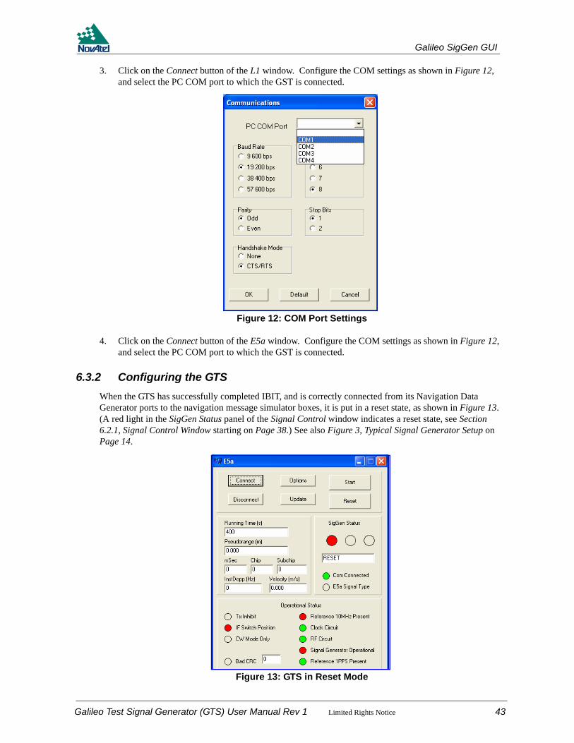
Galileo SigGen GUI
3. Click on the Connect button of the L1 window. Configure the COM settings as shown in Figure 12, and select the PC COM port to which the GST is connected.
Figure 12: COM Port Settings
4. Click on the Connect button of the E5a window. Configure the COM settings as shown in Figure 12, and select the PC COM port to which the GST is connected.
6.3.2 Configuring the GTSWhen the GTS has successfully completed IBIT, and is correctly connected from its Navigation Data Generator ports to the navigation message simulator boxes, it is put in a reset state, as shown in Figure 13. (A red light in the SigGen Status panel of the Signal Control window indicates a reset state, see Section 6.2.1, Signal Control Window starting on Page 38.) See also Figure 3, Typical Signal Generator Setup on Page 14.
Figure 13: GTS in Reset Mode
Galileo Test Signal Generator (GTS) User Manual Rev 1 Limited Rights Notice 43
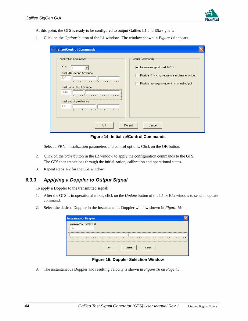
Galileo SigGen GUI
At this point, the GTS is ready to be configured to output Galileo L1 and E5a signals:
1. Click on the Options button of the L1 window. The window shown in Figure 14 appears.
Figure 14: Initialize/Control Commands
Select a PRN, initialization parameters and control options. Click on the OK button.
2. Click on the Start button in the L1 window to apply the configuration commands to the GTS.The GTS then transitions through the initialization, calibration and operational states.
3. Repeat steps 1-2 for the E5a window.
6.3.3 Applying a Doppler to Output SignalTo apply a Doppler to the transmitted signal:
1. After the GTS is in operational mode, click on the Update button of the L1 or E5a window to send an update command.
2. Select the desired Doppler in the Instantaneous Doppler window shown in Figure 15:
Figure 15: Doppler Selection Window
3. The instantaneous Doppler and resulting velocity is shown in Figure 16 on Page 45:
44 Galileo Test Signal Generator (GTS) User Manual Rev 1 Limited Rights Notice
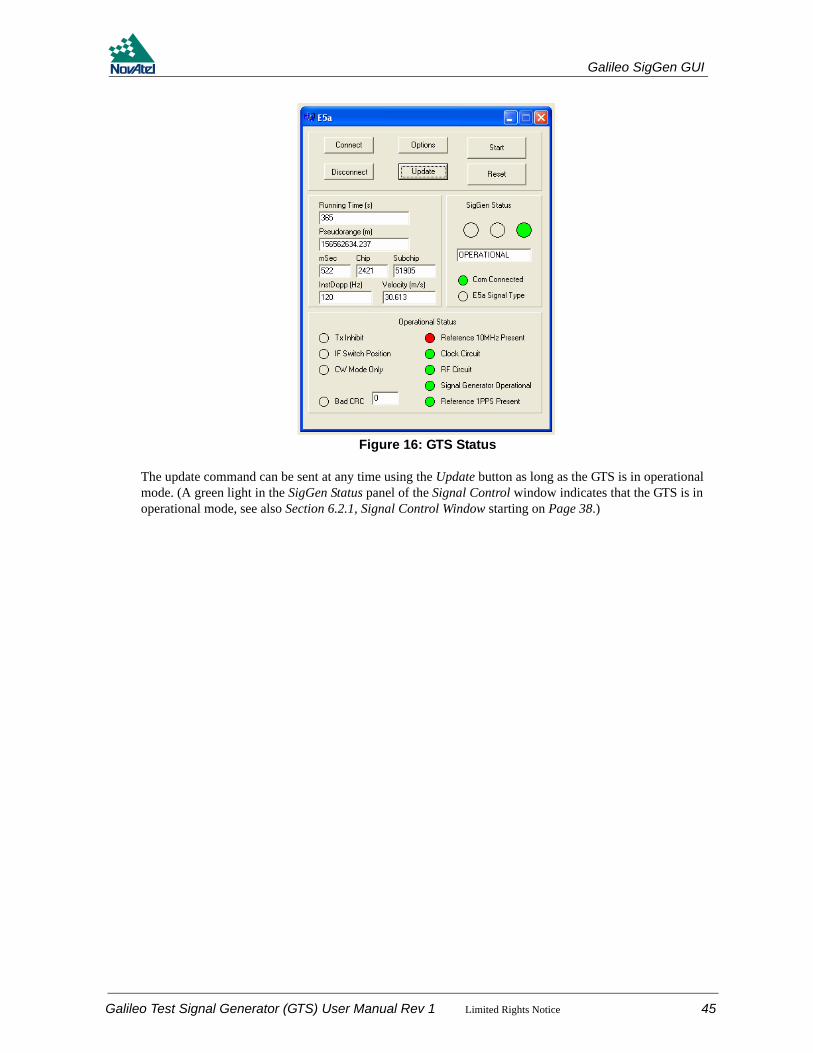
Galileo SigGen GUI
Figure 16: GTS Status
The update command can be sent at any time using the Update button as long as the GTS is in operational mode. (A green light in the SigGen Status panel of the Signal Control window indicates that the GTS is in operational mode, see also Section 6.2.1, Signal Control Window starting on Page 38.)
Galileo Test Signal Generator (GTS) User Manual Rev 1 Limited Rights Notice 45

Appendix A Technical Specifications
A.1 Galileo Test Signal Generator
PHYSICALSize 449 mm (17.7”) x 426 mm (16.8”) x 133 mm (5.2”)
Weight 8.03 kilograms (17.7 lb.)
MECHANICAL DRAWINGSThe dimensions in Figure 17 are in millimeters.
Figure 17: GTS Dimensions
ENVIRONMENTALOperating Temperature 0° C to +50° C
Storage Temperature -40°C to +85°C
Humidity Not to exceed 90% non-condensing
46 Galileo Test Signal Generator (GTS) User Manual Rev 1 Limited Rights Notice
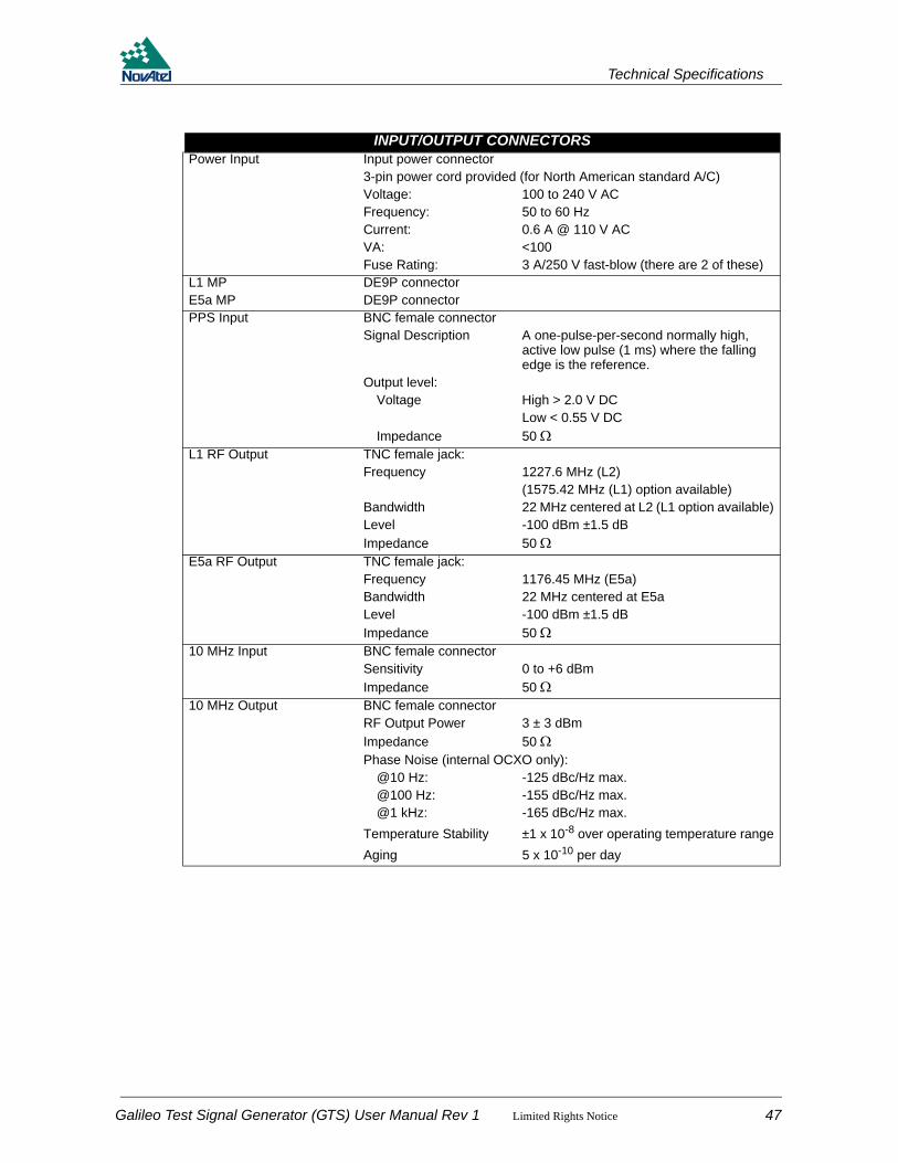
Technical Specifications
INPUT/OUTPUT CONNECTORSPower Input Input power connector
3-pin power cord provided (for North American standard A/C)Voltage: 100 to 240 V ACFrequency: 50 to 60 HzCurrent: 0.6 A @ 110 V ACVA: <100Fuse Rating: 3 A/250 V fast-blow (there are 2 of these)
L1 MPE5a MP
DE9P connectorDE9P connector
PPS Input BNC female connectorSignal Description A one-pulse-per-second normally high,
active low pulse (1 ms) where the falling edge is the reference.
Output level:Voltage High > 2.0 V DC
Low < 0.55 V DCImpedance 50 Ω
L1 RF Output TNC female jack:Frequency 1227.6 MHz (L2)
(1575.42 MHz (L1) option available)Bandwidth 22 MHz centered at L2 (L1 option available)Level -100 dBm ±1.5 dBImpedance 50 Ω
E5a RF Output TNC female jack:Frequency 1176.45 MHz (E5a)Bandwidth 22 MHz centered at E5aLevel -100 dBm ±1.5 dBImpedance 50 Ω
10 MHz Input BNC female connectorSensitivity 0 to +6 dBmImpedance 50 Ω
10 MHz Output BNC female connectorRF Output Power 3 ± 3 dBmImpedance 50 ΩPhase Noise (internal OCXO only):
@10 Hz: -125 dBc/Hz max.@100 Hz: -155 dBc/Hz max.@1 kHz: -165 dBc/Hz max.
Temperature Stability ±1 x 10⁻⁸ over operating temperature rangeAging 5 x 10⁻¹⁰ per day
Galileo Test Signal Generator (GTS) User Manual Rev 1 Limited Rights Notice 47

Technical Specifications
A.1.1 Connector Pin-OutsTable 40 and Table 41 show details of the connector pin-outs on the GTS.
Table 40: L1 and E5a MP Connector Pin-Out Descriptions
Table 41: L1 and E5a Navigation Data Generator Connector Pin-Out Descriptions
Connector Pin No. Direction Name1 Reserved2 Out TxD3 In RxD4 Reserved5 GND6 Reserved7 In CTS8 Out RTS9 Reserved
Connector Pin No. Direction Name1 GND2 Out MSGCLKa3 In MSGRDYa4 Reserved5 In MSGRDATAa
6 In RESETa
7 GND8 Reserved9 In TXINHb
10Reserved11
1213 In MSGDATAb14 Out MSGCLKb15 Reserved16 In MSGRDYb17 In TXINHa18
Reserved19202122 In RESETb23
Reserved2425
48 Galileo Test Signal Generator (GTS) User Manual Rev 1 Limited Rights Notice

Technical Specifications
A.1.2 Cables
A.1.2.1 Power Cable
The power cable supplied with the GTS connects from the Power Input port on the back of the GTS to an external power source (+100 to +240 V AC). An input voltage of less than +100 V AC causes the unit to suspend operation while an input voltage greater than +240 V AC may physically damage the unit, voiding the warranty. The power supply automatically adapts its input power to the national power source in the country of use as long as it is within the above range and you have an adapter for your local power receptacle.
Figure 18: Power Cable
Galileo Test Signal Generator (GTS) User Manual Rev 1 Limited Rights Notice 49
Appendix B Galileo
This appendix is intended to give you information on the Galileo1 signals and their use. For extended Global Positioning System (GPS) and Satellite-Based Augmentation System (SBAS) information, both of which are used by the Galileo Test Receiver, please refer to the GPS+ Reference Manual available from our website at http://www.novatel.com/Downloads/docupdates.html.
B.1 Overview
Galileo will be Europe's own global navigation satellite system, providing a highly accurate, guaranteed global positioning service under civilian control. It will be inter-operable with GPS and GLONASS, the two other global satellite navigation systems.
A user will be able to take a position with the same receiver from any of the satellites in any combination. By offering dual frequencies as standard, however, Galileo will deliver real-time positioning accuracy down to the metre range, which is unprecedented for a publicly available system.
It will guarantee availability of the service under all but the most extreme circumstances and will inform users within seconds of a failure of any satellite. This will make it suitable for applications where safety is crucial, such as running trains, guiding cars and landing aircraft.
The first experimental satellite, part of the so-called Galileo System Test Bed (GSTB) will be launched in the second semester of 2005. The objective of this experimental satellite is to characterize the critical technologies, which are already in development under European Space Agency (ESA) contracts. Thereafter up to four operational satellites will be launched in the 2007-2008 time frame to validate the basic Galileo space and related ground segment. Once this In-Orbit Validation (IOV) phase has been completed, the remaining satellites will be installed to reach the Full Operational Capability (FOC) in 2010.
The fully deployed Galileo system consists of 30 satellites (27 operational + 3 active spares), positioned in three circular Medium Earth Orbit (MEO) planes in 23616 km altitude above the Earth, and at an inclination of the orbital planes of 56 degrees with reference to the equatorial plane. Once this is achieved, the Galileo navigation signals will provide a good coverage even at latitudes up to 75 degrees north, which corresponds to the North Cape, and beyond. The large number of satellites together with the optimisation of the constellation, and the availability of the three active spare satellites, will ensure that the loss of one satellite has no discernible effect on the user.
Two Galileo Control Centres (GCC) will be implemented on European ground to provide for the control of the satellites and to perform the navigation mission management. The data provided by a global network of twenty Galileo Sensor Stations (GSS) will be sent to the Galileo Control Centres through a redundant communications network. The GCC's will use the data of the Sensor Stations to compute the integrity information and to synchronize the time signal of all satellites and of the ground station clocks. The exchange of the data between the Control Centres and the satellites will be performed through so-called up-link stations. Five S-band up-link stations and 10 C-band up-link stations will be installed around the globe for this purpose.
As a further feature, Galileo will provide a global Search and Rescue (SAR) function, based on the operational search and rescue satellite aided tracking Cospas-Sarsat system. To do so, each satellite will be equipped with a transponder, which is able to transfer the distress signals from the user transmitters to the Rescue Co-ordination Centre (RCC), which will then initiate the rescue operation. At the same time, the system will provide a signal to the user, informing them that their situation has been detected and that help is under way. This latter feature is new and is considered a major upgrade compared to the existing system, which does not provide a feedback to the user.
Five categories of services have been defined:
1. A free Open Service (OS)
2. A highly reliable Commercial Service (CS)
1. Galileo Overview information from ESA Navigation website - http://www.esa.int/export/esaNA/GGGMX650NDC_index_0.html
50 Galileo Test Signal Generator (GTS) User Manual Rev 1 Limited Rights Notice
Galileo
3. A Safety-of-Life Service (SOL)
4. A government encrypted Public Regulated Service (PRS)
5. A Search and Rescue Service (SAR)
B.1.1 Open ServiceThis single-frequency service will involve the provision of a positioning, navigation and precise timing service. It will be available for use by any person in possession of a Galileo receiver. No authorisation will be required to access this service. Galileo is expected to be similar to GPS in this respect.
The principal applications will be general navigation and positioning, network timing, traffic information systems, systems including information on alternative routes in the event of congestion, and wireless location, for example, with mobile telephony.
Studies clearly show that the availability of these services will be significantly enhanced by the existence of a greater number of satellites, as is the case when both GPS and Galileo are in operation. This is particularly important for land-based services, such as private car navigation, where service is mostly required in down town cores and where satellite shadowing is minimised by the combination of the systems.
The Open Service will be transmitted in the E5a frequency band at 1176.45 MHz.
B.1.2 Commercial ServiceService providers using the multi-frequency commercial services will have the opportunity to give added value to their range of products for which they can charge the end customer and will, in turn, pay a fee to the Galileo operator. The signal will contain data relating to the additional commercial services being offered. In return for the fee, the Galileo operator will be able to offer certain service guarantees. This aspect of service guarantee and the commensurate liabilities is one area where Galileo is significantly differentiated from GPS. A key component in achieving this is an independent system within Galileo for monitoring the satisfactory working of the system and informing the end user of this by an integrity signal incorporated in the data stream.
The main applications for this service concern professional users who are ready to pay for a service guaranteed by the Galileo operator, notably in the areas of technical surveys, in activities involving customs and excise operations, network synchronisation, sea fleet management, vehicle fleet management, and road tolls.
Controlled access to this service for end-users and the providers of value-added services will be based on protected access keys in the receivers. This will also enable revenue to be collected from users.
The commercial service will be transmitted in the E6 frequency band at 1278.75 MHz.
B.1.3 Safety-of-Life ServiceThe safety-of-life service will be offered to users who are highly dependant on precision, signal quality and signal transmission reliability. It will offer a high level of integrity, and consequently, provide the user with a very rapid warning of any possible malfunctions. It will need to be certified in accordance with the regulations applicable to the various modes of transport (the International Civil Aviation Organization (ICAO) regulations in the case of air transport; the International Maritime Organization (IMO) regulations in the case of sea transport). This service will require specialised receivers providing access to this enhanced-quality signal.
The safety-of-life service will be transmitted in two frequency bands – L1 at 1575.42 MHz, and E5b at 1207.14 MHz. Users may receive signals from the two frequency bands independently.
Galileo Test Signal Generator (GTS) User Manual Rev 1 Limited Rights Notice 51
Galileo
B.1.4 Public Regulated ServiceThe PRS will be a restricted access service, offered to government agencies that require a high availability navigation signal. The PRS service will utilize ranging codes that are encrypted with a highly secure government encryption scheme. To enhance availability, the PRS service is intended to have anti-jamming and anti-spoofing capabilities.
The PRS will be transmitted in two frequency bands – L1 at 1575.42 MHz, and E6 at 1278.75 MHz. Users may receive signals from the two frequency bands independently.
B.1.5 Search and Rescue ServiceA specific public service designed to assist in search and rescue operations will make it possible to locate person and vehicles in distress. The vehicles will be fitted with beacons, which having been activated in the event of an emergency will send an alerting signal to the rescue centre.
The Galileo Programme provides this search and rescue service for users based on humanitarian and public service principles of the international COSPAS-SARSAT system while at the same time making search and rescue operations more effective.
52 Galileo Test Signal Generator (GTS) User Manual Rev 1 Limited Rights Notice
Appendix C Acronyms1PPS One Pulse Per Second
AGC Automatic Gain ControlARNS Aeronautical Radio Navigation ServicesASCII American Standard Code for Information Interchange
BDE Borland Database EngineBSG Baseband Signal Generator
C/A Code Coarse/Acquisition CodeCCITT Command, Control, and Intelligence Technical TestCDMA Code-Division-Multiple-AccessCMR Compact Measurement RecordCOSPAS Cosmitscheskaja Sistema Poiska Awarinitsch Sudow (Russian: space system for search of vessels
in distress)CR Carriage ReturnCRC Cyclic Redundancy CheckCS Commercial ServiceCTS Clear To SendCW Continuous Wave
dB DecibelDCD Data Carrier DetectedDDS Direct Digital SamplingDoD Department of DefenseDTE Data Terminal EquipmentDTR Data Terminal Ready
ESA European Space AgencyESD Electrostatic Discharge
FDA Frequency Distribution AmplifierFEC Forward Error CorrectionFIFO First In, First OutFOC Full Operational CapabilityFPGA Field Programmable Gate Array
GCC Galileo Control CentreGEO Geo-stationary Earth OrbitGLONASS Global Navigation Satellite SystemGND GroundGPS Global Positioning SystemGSS Galileo Sensor StationsGSTB Galileo System Test BedGTR Galileo Test ReceiverGTS Galileo Test Signal GeneratorGUS Ground Uplink Station
I and Q In-Phase and QuadratureIBIT Initiated Built-In TestICAO International Civil Aviation OrganizationIF Intermediate FrequencyIMO International Maritime OrganizationINH InhibitIOV In-Orbit ValidationISG IF Signal Generator
JTAG Joint Test Action Group
KPA Klystron Power Amplifier
LED Light Emitting Diode LF Line FeedLNA Low Noise Amplifier
Galileo Test Signal Generator (GTS) User Manual Rev 1 Limited Rights Notice 53

Acronyms
LO Local OscillatorLSB Least Significant BitLSG Loopback Signal Generator
MEO Medium Earth OrbitMSB Most Significant BitMP Message Processor
N/C Not ConnectedNH Neuman-Hoffman
OCXO Oven Controlled Crystal OscillatorOEM Original Equipment ManufacturerOS Open Service
PAC Pulse Aperture CorrelatorPC Personal ComputerPIN Position IndicatorPLL Phase Lock LoopPPS Pulse Per SecondPRN Pseudo Random NumberPRS Public Regulated Service
RCC Rescue Co-ordination CentreRF Radio FrequencyRFU Radio Frequency UplinkRMA Return Material AuthorizationRTS Request To SendRXD Received Data
SAR Search and RescueSARSAT Search and Rescue Satellite Aided TrackingSBAS Satellite-Based Augmentation SystemSOL Safety-of-LifeSPS Symbols Per SecondSV Space Vehicle
TTL Transistor-Transistor LogicTX TransmitTXD Transmitted Data
UART Universal Asynchronous Receiver-Transmitter
V AC Volts Alternating Current V DC Volts Direct Current
WAAS Wide Area Augmentation System
54 Galileo Test Signal Generator (GTS) User Manual Rev 1 Limited Rights Notice

Index
Index10 MHz reference, 16, 191PPS, 13, 17–18, 30, 34
Aaccessories, 12, 16acquisition, 53acronyms, 53adapter, 49antenna and cable, 19
Bbandwidth, 20baud rate, 21bidirectional communication, 21binary-phase shift keying, 11BNC connector, 19
Ccables, 15, 17check, 36–37code signals, 26, 30command message identifiers, 23communication, 21configuration, 15, 21connections, 17, 19, 47–48continuous wave switch, 16, 18copyright, 2cyclic redundancy check, 36–37
Ddefault port settings, 21directional communication, 21dongles, 14–15, 18
Eenclosure, 11error, 31–32, 37
Ffeatures, 11field programmable gate array, 35firmware, 35flowchart, command, 28functional overview, 12fuse, 17
Galileo Test Signal Generator (GTS) User Manual Rev 1 Limited
GGalileo, 50Graphical User Interface (GUI), 38
Hhandshaking, 21hardware, 16, 33–34
II channel, 26indication flag, L1 or L5, 23inhibit L1 or L5, 16initialization, 25–26input command flowchart, 28integration, 10intermediate frequency, 19introduction, 11
LLED, 16–17
Nnavigation data generator, 18, 21
Ooperation, 21oscillator, 19overview, 12, 14, 50
Ppacket synchronization, 23parity, 21phase noise, 20pin-outs, 48ports, 15, 17, 19power, 17, 49pulse, 53–54
QQ channel, 26quick start, 15
Rradio frequency, 19rear panel, 17reset, 27, 34
Rights Notice 55

Index
revision, manual, 58
Ssafety computer, 13self-test, 13, 17serial cable, 15setting up, 14status message, 29–30, 36sub-chip phase, 26sub-phase, 30supply voltage, 17switch, 30–31
Ttechnical specifications, 46–49timing, 22
Uuplink range, 30
Vversion, 35voltage, 17, 49
Wwarnings, 17warranty, 9
56 Galileo Test Signal Generator
(GTS) User Manual Rev 1 Limited Rights Notice
Galileo Test Signal Generator (GTS) User Manual Rev 1 Limited
Rights Notice 57
OM-20000092 Rev 1 2006/04/25
Recyclable
Printed in Canada on recycled paper


