Page 1
Gamcorp (Melbourne) Pty Ltd A.C.N 141 076 904 A.B.N 73 015 060 240www.gamcorp.com.au Email: [email protected] 4, 346 Ferntree Gully Rd, Notting Hill VIC 3149. Tel: 03 9543 2211 Fax: 03 9543 4046
Our Ref: 2242/K.Z
28 July 2016
Xiamen Hopergy Photovoltaic Technology Co. Ltd.No.630, Tonghong RoadTongan District, Xiamen 361100China
PV Array Frame Engineering Certification
Installation of Hopergy Adjustable Tilt Leg Roof Mount Solar System with HOP-SLR02 Rails
Gamcorp (Melbourne) Pty Ltd, being Structural Engineers within the meaning of Australian andNew Zealand Building Regulations, have carried out a structural design check of Hopergy Adjustable Tilt Leg Roof Mount Solar System installation within Australia and New Zealand. Thedesign check has been based on the information in the schematic drawings of the system components and test report provided by Hopergy Australia (IMSOLAR).
We find the Installation of Hopergy Adjustable Tilt Leg Roof Mount Solar System for Australian and New Zealand use to be structurally sufficient based on the following conditions:
• Wind loads to AS/NZ1170.2:2011 Admt 3-2013• Wind region A, B, C, D, W• Wind terrain category 2 & 3• Wind average recurrence interval of 500 years• Maximum building height 20m• The PV panel dimensions to be 1640mm x 992mm and 2000mm x 1000mm• Maximum weight of the PV panel and array frame to be 15 kg/m2
• Rails to be HOP-SLR02• The assessment of the rail is based on a deflection limit of 20mm specified by Hopergy
Australia (IMSOLAR) as per the test report provided• The roof interface to be Hopergy adjustable tilt leg as per drawing HOP-ARL01-15/30/60
and front leg as per drawing HOP-FB002-30• The assessment is based on an assumption that the front leg and tilt leg meet the
industrial standard requirements• Each PV panel to be installed using 2 rails minimum in all circumstances• Installation of PV array to be done in accordance with the PV installation manual• The certification excludes assessment of roof structure and PV panels
Refer to attached summary table for interface spacing
NOTES:• The recommended spacing nominated in this certification is based on the
capacity of the array frame, not the roof structure and PV panel. It is the responsibility of the installer to adopt the most critical spacing.
Page 1 of 2ISO 9001:2008 Registered Firm
Certificate No: AU1222
Page 2
Gamcorp (Melbourne) Pty Ltd A.C.N 141 076 904 A.B.N 73 015 060 240www.gamcorp.com.au Email: [email protected] 4, 346 Ferntree Gully Rd, Notting Hill VIC 3149. Tel: 03 9543 2211 Fax: 03 9543 4046
• This is the up-to-date certification. All previous certifications for Hopergy products issued by Gamcorp Pty Ltd are no longer valid.
• If any of the above conditions cannot be met, the structural engineer must be notified immediately.
Construction is to be carried out strictly in accordance with the manufacturers instructions. This work was designed in accordance with the provisions of Australian and New Zealand Building Regulations and in accordance with sound, widely accepted engineering principles.
Yours faithfully,Gamcorp (Melbourne) Pty Ltd
Martin Gamble Mudi Ariyarathna Managing Director B.Eng(Civil)(Hons)Monash, M.Eng&Mgt, MIEAust, MAICD CPEng, NPER, RBP EC-39699, RPEQ- 15899
Page 2 of 2ISO 9001:2008 Registered Firm
Certificate No: AU1222
Page 3
with HOP-SLR02 Rail
For: Xiamen Hopergy PhotovoltaicTechnology Co. Ltd.
Job Number: 2242Date: 27 July 2016
Structural Design Documentation
Solar Adjustable Tilt Legs System Spacing Table
According to AS 1170.2-2011 Amdt 3-2013
within Australia & New Zealand
Terrain Category 2 & 3
Gamcorp (Melbourne) Pty Ltd Consulting Structural & Civil Engineers
A.C.N 141 076 904 A.B.N 73 015 060 240
www.gamcorp.com.au
[email protected]
COPYRIGHT: The concepts and information contained in this document are the property of Gamcorp (Melbourne) Pty Ltd. Use or copying of this document in whole or in part without the written permission of Gamcorp constitutes an infringement of copyright.
LIMITATION: This report has been prepared on behalf of and for the exclusive use of Gamcorp (Melbourne) Pty Ltd’s Client, and is subject to and issued in connection with the provisions of the agreement between Gamcorp (Melbourne) Pty Ltd and its Client. Gamcorp (Melbourne) Pty Ltd accepts no liability or responsibility whatsoever for or in respect of any use of or reliance upon this report by any third party.
Page 4
Client Name
Job No:
Client:
Project:
Address:
Australian/New Zealand Standards
AS/NZS 1170. 2011 – Structural Design Actions
Part 0 – General Principles
Part 1 – Permanent imposed and other actions
Part 2 – Wind Actions
Part 3 – Snow and Ice Actions
AS/NZS 1252 – High Strength Structural Bolting
AS 4055 – Wind Loads for Housing
AS 4100 – Steel Structures
AS/NZS 4600 – Cold-Formed Steel Structures
WTC 2 & 3
Designed: K.Z
Date: Jul-16
2242
Xiamen Hopergy Photovoltaic Technology Co. Ltd.
Solar Adjustable Tilt Legs System Spacing Table
within Australia & New Zealand
Wind Terrain Category:
Suite 4, 346 Ferntree Gully Road Notting Hill VIC 3168
Tel: 03 9543 2211 Fax: 03 9543 4046
[email protected] www.gamcorp.com.au
ISO 9001:2008 Registered Firm
Certificate No: AU1222
Page 5
Client: Job:
Project: Date:Address:
Designed: Checked: M.APV Frame Spacing Table for Adjustable Tilt Leg System
Type of Rail HOP-SLR02
Type of Interface Adjustable Tilt Leg
Solar Panel Dimension 1.64m x 0.99m
Terrain category 2
Type of Interface 10°-15° Adjustable Tilt Leg
Roof Angle (Φ) – ≤10°
Corner EdgeInterm
ediateInternal Corner Edge
Interm
ediateInternal Corner Edge
Interm
ediateInternal Corner Edge
Inter
mediat
e
Internal
A 925 1416 1793 2018 760 1160 1573 1908 688 1047 1418 1855 649 987 1336 1825
B 568 862 1164 1792 468 709 956 1464 424 642 864 1320 400 606 815 1244
C 381 576 775 1182 315 475 638 970 285 430 577 877 269 406 545 827
D 235 354 474 719 194 292 392 592 176 265 355 536 166 250 335 506
W 714 1087 1473 1847 588 893 1206 1751 532 807 1089 1673 502 761 1027 1575
Type of Interface 15°-30° Adjustable Tilt Leg
Roof Angle (Φ) – ≤10°
Corner EdgeInterm
ediateInternal Corner Edge
Interm
ediateInternal Corner Edge
Interm
ediateInternal Corner Edge
Inter
mediat
e
Internal
A 505 765 1032 1584 416 630 848 1296 377 570 767 1169 356 538 723 1102
B 312 471 633 962 258 389 521 791 234 352 472 715 221 333 446 675
C 210 317 424 642 174 262 350 529 157 237 317 479 149 224 300 452
D 130 195 261 394 107 162 216 325 97 146 196 295 92 138 185 278
W 391 592 796 1214 323 488 655 997 292 441 592 900 276 417 559 849
Type of Interface 30° Adjustable Tilt Leg
Roof Angle (Φ) – ≤10°
Corner EdgeInterm
ediateInternal Corner Edge
Interm
ediateInternal Corner Edge
Interm
ediateInternal Corner Edge
Inter
mediat
e
Internal
A 411 622 838 1280 340 513 689 1050 308 464 623 948 290 438 588 894
B 255 384 515 781 210 317 425 643 191 287 385 582 180 271 363 549
C 172 258 346 523 142 214 286 431 129 194 259 390 122 183 244 369
D 106 160 213 321 88 132 176 266 80 120 160 241 75 113 151 227
W 319 482 647 984 263 397 533 809 239 360 482 731 226 340 456 690
within Australia & New Zealand
Xiamen Hopergy Photovoltaic Technology Co. Ltd. 2242
Solar Adjustable Tilt Legs System Spacing Table Jul-16
K.Z
Wind
Region
Building Height – H (m)
H≤5 5<H≤10 10<H≤15 15<H≤20
Wind
Region
Building Height – H (m)
H≤5 5<H≤10 10<H≤15 15<H≤20
Wind
Region
Building Height – H (m)
H≤5 5<H≤10 10<H≤15 15<H≤20
ISO 9001:2008 Registered Firm
Certificate No: AU1222 Page 1 of 12
Page 6
PV Frame Spacing Table for Adjustable Tilt Leg System
Type of Rail HOP-SLR02
Type of Interface Adjustable Tilt Leg
Solar Panel Dimension 1.64m x 0.99m
Terrain category 2
Type of Interface 30°-60° Adjustable Tilt Leg
Roof Angle (Φ) – ≤10°
Corner EdgeInterm
ediateInternal Corner Edge
Interm
ediateInternal Corner Edge
Interm
ediateInternal Corner Edge
Inter
mediat
e
Internal
A 322 486 653 994 266 401 538 817 241 363 487 738 228 343 460 697
B 200 301 403 609 165 248 332 502 150 225 301 455 141 213 284 429
C 135 203 271 409 111 167 224 337 101 152 203 306 95 143 192 289
D 83 125 167 252 69 104 138 208 63 94 125 189 59 89 118 178
W 250 377 505 766 207 311 417 631 187 282 377 571 177 266 356 539
Type of Interface 30°-60° Adjustable Tilt Leg
Roof Angle (Φ) – 10°-20°
Corner EdgeInterm
ediateInternal Corner Edge
Interm
ediateInternal Corner Edge
Interm
ediateInternal Corner Edge
Inter
mediat
e
Internal
A 505 765 1032 1584 416 630 848 1296 377 570 767 1169 356 538 723 1102
B 312 471 633 962 258 389 521 791 234 352 472 715 221 333 446 675
C 210 317 424 642 174 262 350 529 157 237 317 479 149 224 300 452
D 130 195 261 394 107 162 216 325 97 146 196 295 92 138 185 278
W 391 592 796 1214 323 488 655 997 292 441 592 900 276 417 559 849
Type of Interface 30°-60° Adjustable Tilt Leg
Roof Angle (Φ) – 20°-30°
Corner EdgeInterm
ediateInternal Corner Edge
Interm
ediateInternal Corner Edge
Interm
ediateInternal Corner Edge
Inter
mediat
e
Internal
A 925 1416 1793 2018 760 1160 1573 1908 688 1047 1418 1855 649 987 1336 1825
B 568 862 1164 1792 468 709 956 1464 424 642 864 1320 400 606 815 1244
C 381 576 775 1182 315 475 638 970 285 430 577 877 269 406 545 827
D 235 354 474 719 194 292 392 592 176 265 355 536 166 250 335 506
W 714 1087 1473 1847 588 893 1206 1751 532 807 1089 1673 502 761 1027 1575
Wind
Region
Building Height – H (m)
H≤5 5<H≤10 10<H≤15 15<H≤20
Wind
Region
Building Height – H (m)
H≤5 5<H≤10 10<H≤15 15<H≤20
Wind
Region
Building Height – H (m)
H≤5 5<H≤10 10<H≤15 15<H≤20
ISO 9001:2008 Registered Firm
Certificate No: AU1222 Page 2 of 12
Page 7
General Notes
Note 1 Screws minimum embedment length into timber 35 mm
Note 2 Recommended screws
Note 3 Following components are satisfied to use according to AS1170.2011
Note 4 For adjustable tilting leg,
Maximum back leg angle to horizontal - 90°Minimum back leg angle to horizontal - 30°
Note 5 Refer Figure 5.3 of AS/NZS 1170.2:2011 for definition
of roof zones.
Note 6 Terrain category 2 (TC2) refers to open terrain, including grassland, with well-scattered
obstructions having heights generally from 1.5 m to 5 m, with no more than two obstruction
per obstructions per hectare.
Metal Purlins/Battens Fasteners to use
0.55 mm – 1.5 mm M6-11 TPI RoofZips
1.9 mm M6-11 TPI RoofZips OR 12g-14 TPI Teks screws
2.4 mm and Above 12g-24 TPI Teks screws
Wood purlins and Rafter
HOP-SLR02 Rail HOP-SLR02
Tilt Legs
Fasteners to use
Pine and Hardwood (35mm embedment and
above)M6 (12g) with 10 TPI
Components Part Number Description
Adjustable Tilt Legs Kit (front and back leg)
HOP-SLR02 Rail
ISO 9001:2008 Registered Firm
Certificate No: AU1222 Page 3 of 12
Page 8
Client: Job:
Project: Date:Address:
Designed: Checked: M.APV Frame Spacing Table for Adjustable Tilt Leg System
Type of Rail HOP-SLR02
Type of Interface Adjustable Tilt Leg
Solar Panel Dimension 1.64m x 0.99m
Terrain category 3
Type of Interface 10°-15° Adjustable Tilt Leg
Roof Angle (Φ) – ≤10°
Corner EdgeInterm
ediateInternal Corner Edge
Interm
ediateInternal Corner Edge
Interm
ediateInternal Corner Edge
Inter
mediat
e
Internal
A 1311 1465 1589 1796 1311 1465 1589 1796 1157 1409 1527 1720 1033 1368 1481 1664
B 819 1248 1542 1738 819 1248 1542 1738 710 1079 1457 1666 635 963 1299 1613
C 549 832 1120 1552 549 832 1120 1552 476 721 969 1480 426 644 866 1319
D 338 510 684 1039 338 510 684 1039 293 442 593 899 263 396 530 804
W 1031 1349 1459 1639 1031 1349 1459 1639 892 1299 1404 1573 797 1214 1363 1525
Type of Interface 15°-30° Adjustable Tilt Leg
Roof Angle (Φ) – ≤10°
Corner EdgeInterm
ediateInternal Corner Edge
Interm
ediateInternal Corner Edge
Interm
ediateInternal Corner Edge
Inter
mediat
e
Internal
A 728 1107 1349 1509 728 1107 1349 1509 631 957 1292 1451 564 855 1152 1408
B 449 679 913 1393 449 679 913 1393 390 589 791 1204 349 527 707 1074
C 302 456 611 927 302 456 611 927 263 396 530 803 235 354 474 718
D 187 281 376 568 187 281 376 568 162 244 326 492 145 219 292 441
W 563 854 1150 1388 563 854 1150 1388 489 740 995 1336 437 661 889 1298
Type of Interface 30° Adjustable Tilt Leg
Roof Angle (Φ) – ≤10°
Corner EdgeInterm
ediateInternal Corner Edge
Interm
ediateInternal Corner Edge
Interm
ediateInternal Corner Edge
Inter
mediat
e
Internal
A 593 899 1212 1426 593 899 1212 1426 514 778 1048 1373 460 696 936 1333
B 366 553 743 1129 366 553 743 1129 318 480 644 977 285 429 576 873
C 247 372 498 754 247 372 498 754 214 323 432 653 192 289 387 584
D 153 229 307 463 153 229 307 463 133 199 266 402 119 179 239 359
W 459 695 934 1314 459 695 934 1314 399 602 809 1231 357 539 723 1099
within Australia & New Zealand
Xiamen Hopergy Photovoltaic Technology Co. Ltd. 2242
Solar Adjustable Tilt Legs System Spacing Table Jul-16
K.Z
Wind
Region
Building Height – H (m)
H≤5 5<H≤10 10<H≤15 15<H≤20
Wind
Region
Building Height – H (m)
H≤5 5<H≤10 10<H≤15 15<H≤20
Wind
Region
Building Height – H (m)
H≤5 5<H≤10 10<H≤15 15<H≤20
ISO 9001:2008 Registered Firm
Certificate No: AU1222 Page 4 of 12
Page 9
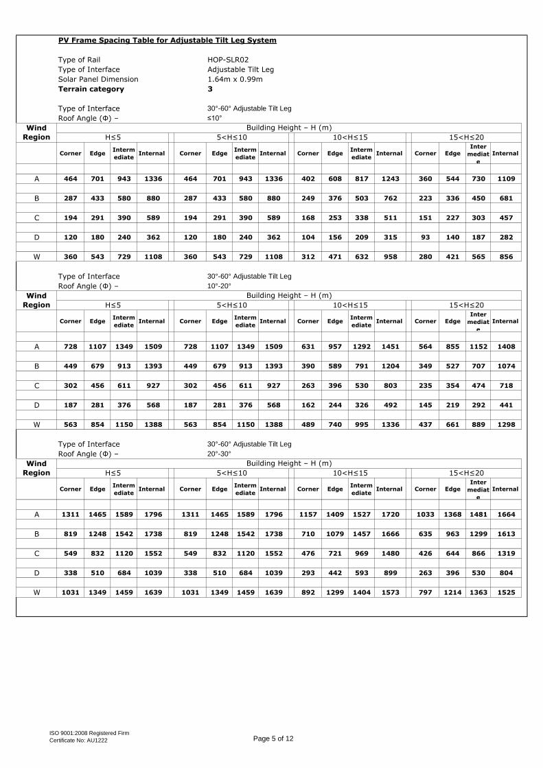
PV Frame Spacing Table for Adjustable Tilt Leg System
Type of Rail HOP-SLR02
Type of Interface Adjustable Tilt Leg
Solar Panel Dimension 1.64m x 0.99m
Terrain category 3
Type of Interface 30°-60° Adjustable Tilt Leg
Roof Angle (Φ) – ≤10°
Corner EdgeInterm
ediateInternal Corner Edge
Interm
ediateInternal Corner Edge
Interm
ediateInternal Corner Edge
Inter
mediat
e
Internal
A 464 701 943 1336 464 701 943 1336 402 608 817 1243 360 544 730 1109
B 287 433 580 880 287 433 580 880 249 376 503 762 223 336 450 681
C 194 291 390 589 194 291 390 589 168 253 338 511 151 227 303 457
D 120 180 240 362 120 180 240 362 104 156 209 315 93 140 187 282
W 360 543 729 1108 360 543 729 1108 312 471 632 958 280 421 565 856
Type of Interface 30°-60° Adjustable Tilt Leg
Roof Angle (Φ) – 10°-20°
Corner EdgeInterm
ediateInternal Corner Edge
Interm
ediateInternal Corner Edge
Interm
ediateInternal Corner Edge
Inter
mediat
e
Internal
A 728 1107 1349 1509 728 1107 1349 1509 631 957 1292 1451 564 855 1152 1408
B 449 679 913 1393 449 679 913 1393 390 589 791 1204 349 527 707 1074
C 302 456 611 927 302 456 611 927 263 396 530 803 235 354 474 718
D 187 281 376 568 187 281 376 568 162 244 326 492 145 219 292 441
W 563 854 1150 1388 563 854 1150 1388 489 740 995 1336 437 661 889 1298
Type of Interface 30°-60° Adjustable Tilt Leg
Roof Angle (Φ) – 20°-30°
Corner EdgeInterm
ediateInternal Corner Edge
Interm
ediateInternal Corner Edge
Interm
ediateInternal Corner Edge
Inter
mediat
e
Internal
A 1311 1465 1589 1796 1311 1465 1589 1796 1157 1409 1527 1720 1033 1368 1481 1664
B 819 1248 1542 1738 819 1248 1542 1738 710 1079 1457 1666 635 963 1299 1613
C 549 832 1120 1552 549 832 1120 1552 476 721 969 1480 426 644 866 1319
D 338 510 684 1039 338 510 684 1039 293 442 593 899 263 396 530 804
W 1031 1349 1459 1639 1031 1349 1459 1639 892 1299 1404 1573 797 1214 1363 1525
Wind
Region
Building Height – H (m)
H≤5 5<H≤10 10<H≤15 15<H≤20
Wind
Region
Building Height – H (m)
H≤5 5<H≤10 10<H≤15 15<H≤20
Wind
Region
Building Height – H (m)
H≤5 5<H≤10 10<H≤15 15<H≤20
ISO 9001:2008 Registered Firm
Certificate No: AU1222 Page 5 of 12
Page 10
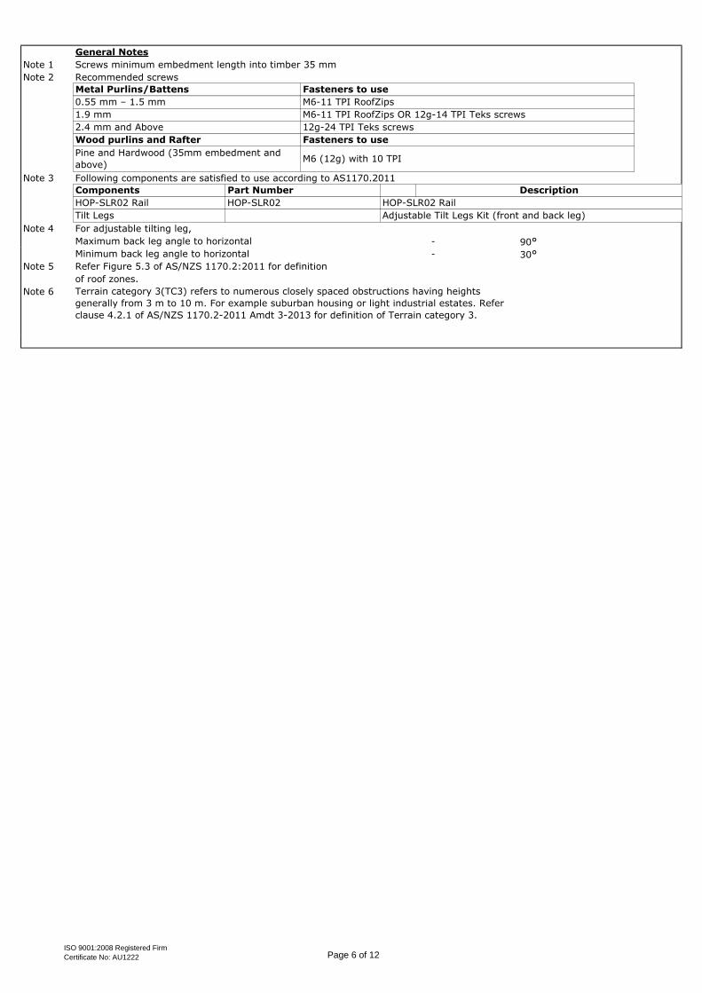
General Notes
Note 1 Screws minimum embedment length into timber 35 mm
Note 2 Recommended screws
Note 3 Following components are satisfied to use according to AS1170.2011
Note 4 For adjustable tilting leg,
Maximum back leg angle to horizontal - 90°Minimum back leg angle to horizontal - 30°
Note 5 Refer Figure 5.3 of AS/NZS 1170.2:2011 for definition
of roof zones.
Note 6 Terrain category 3(TC3) refers to numerous closely spaced obstructions having heights
generally from 3 m to 10 m. For example suburban housing or light industrial estates. Refer
clause 4.2.1 of AS/NZS 1170.2-2011 Amdt 3-2013 for definition of Terrain category 3.
Metal Purlins/Battens Fasteners to use
0.55 mm – 1.5 mm M6-11 TPI RoofZips
1.9 mm M6-11 TPI RoofZips OR 12g-14 TPI Teks screws
2.4 mm and Above 12g-24 TPI Teks screws
Wood purlins and Rafter
HOP-SLR02 Rail HOP-SLR02
Tilt Legs
Fasteners to use
Pine and Hardwood (35mm embedment and
above)M6 (12g) with 10 TPI
Components Part Number Description
Adjustable Tilt Legs Kit (front and back leg)
HOP-SLR02 Rail
ISO 9001:2008 Registered Firm
Certificate No: AU1222 Page 6 of 12
Page 11
Client: Job:
Project: Date:Address:
Designed: Checked: M.APV Frame Spacing Table for Adjustable Tilt Leg System
Type of Rail HOP-SLR02
Type of Interface Adjustable Tilt Leg
Solar Panel Dimension 2m x 1m
Terrain category 2
Type of Interface 10°-15° Adjustable Tilt Leg
Roof Angle (Φ) – ≤10°
Corner EdgeInterm
ediateInternal Corner Edge
Interm
ediateInternal Corner Edge
Interm
ediateInternal Corner Edge
Inter
mediat
e
Internal
A 763 1172 1601 1936 627 959 1304 1828 566 865 1174 1776 534 815 1105 1716
B 467 711 962 1487 385 585 789 1213 349 528 712 1092 329 499 672 1029
C 313 474 639 977 259 391 525 801 234 354 475 723 221 334 448 682
D 193 291 390 593 159 240 322 488 144 218 291 441 136 206 275 416
W 588 898 1220 1768 484 737 997 1543 438 665 899 1388 413 628 848 1305
Type of Interface 15°-30° Adjustable Tilt Leg
Roof Angle (Φ) – ≤10°
Corner EdgeInterm
ediateInternal Corner Edge
Interm
ediateInternal Corner Edge
Interm
ediateInternal Corner Edge
Inter
mediat
e
Internal
A 415 631 852 1313 342 519 699 1072 310 469 632 967 293 443 596 911
B 256 388 521 794 212 320 429 652 192 289 388 589 181 273 366 556
C 173 260 349 529 143 215 288 435 129 195 261 394 122 184 246 372
D 107 160 215 324 88 133 177 267 80 120 161 242 76 114 152 229
W 321 487 656 1004 265 401 539 823 240 363 488 743 227 343 460 700
Type of Interface 30° Adjustable Tilt Leg
Roof Angle (Φ) – ≤10°
Corner EdgeInterm
ediateInternal Corner Edge
Interm
ediateInternal Corner Edge
Interm
ediateInternal Corner Edge
Inter
mediat
e
Internal
A 338 513 691 1058 279 422 568 867 253 382 513 782 239 361 484 738
B 209 316 424 644 173 261 349 530 157 236 316 479 148 223 299 452
C 141 212 284 430 117 175 235 355 106 159 213 321 100 150 201 303
D 87 131 175 264 72 108 145 218 65 98 131 198 62 93 124 187
W 262 396 533 812 216 327 439 667 196 296 397 603 185 279 375 569
Wind
Region
Building Height – H (m)
H≤5 5<H≤10 10<H≤15 15<H≤20
Wind
Region
Building Height – H (m)
H≤5 5<H≤10 10<H≤15 15<H≤20
Wind
Region
Building Height – H (m)
H≤5 5<H≤10 10<H≤15 15<H≤20
within Australia & New Zealand
Xiamen Hopergy Photovoltaic Technology Co. Ltd. 2242
Solar Adjustable Tilt Legs System Spacing Table Jul-16
K.Z
ISO 9001:2008 Registered Firm
Certificate No: AU1222 Page 7 of 12
Page 12
PV Frame Spacing Table for Adjustable Tilt Leg System
Type of Rail HOP-SLR02
Type of Interface Adjustable Tilt Leg
Solar Panel Dimension 2m x 1m
Terrain category 2
Type of Interface 30°-60° Adjustable Tilt Leg
Roof Angle (Φ) – ≤10°
Corner EdgeInterm
ediateInternal Corner Edge
Interm
ediateInternal Corner Edge
Interm
ediateInternal Corner Edge
Inter
mediat
e
Internal
A 265 400 538 820 218 330 443 673 198 299 401 608 187 282 378 574
B 164 247 331 502 135 204 273 413 123 185 247 374 116 175 234 353
C 111 166 223 336 91 137 184 277 83 125 167 251 78 118 157 237
D 68 103 137 207 57 85 114 171 51 77 103 155 48 73 97 146
W 205 310 416 632 170 256 343 520 154 232 310 470 145 219 293 443
Type of Interface 30°-60° Adjustable Tilt Leg
Roof Angle (Φ) – 10°-20°
Corner EdgeInterm
ediateInternal Corner Edge
Interm
ediateInternal Corner Edge
Interm
ediateInternal Corner Edge
Inter
mediat
e
Internal
A 415 631 852 1313 342 519 699 1072 310 469 632 967 293 443 596 911
B 256 388 521 794 212 320 429 652 192 289 388 589 181 273 366 556
C 173 260 349 529 143 215 288 435 129 195 261 394 122 184 246 372
D 107 160 215 324 88 133 177 267 80 120 161 242 76 114 152 229
W 321 487 656 1004 265 401 539 823 240 363 488 743 227 343 460 700
Type of Interface 30°-60° Adjustable Tilt Leg
Roof Angle (Φ) – 20°-30°
Corner EdgeInterm
ediateInternal Corner Edge
Interm
ediateInternal Corner Edge
Interm
ediateInternal Corner Edge
Inter
mediat
e
Internal
A 763 1172 1601 1936 627 959 1304 1828 566 865 1174 1776 534 815 1105 1716
B 467 711 962 1487 385 585 789 1213 349 528 712 1092 329 499 672 1029
C 313 474 639 977 259 391 525 801 234 354 475 723 221 334 448 682
D 193 291 390 593 159 240 322 488 144 218 291 441 136 206 275 416
W 588 898 1220 1768 484 737 997 1543 438 665 899 1388 413 628 848 1305
Wind
Region
Building Height – H (m)
H≤5 5<H≤10 10<H≤15 15<H≤20
Wind
Region
Building Height – H (m)
H≤5 5<H≤10 10<H≤15 15<H≤20
Wind
Region
Building Height – H (m)
H≤5 5<H≤10 10<H≤15 15<H≤20
ISO 9001:2008 Registered Firm
Certificate No: AU1222 Page 8 of 12
Page 13
General Notes
Note 1 Screws minimum embedment length into timber 35 mm
Note 2 Recommended screws
Note 3 Following components are satisfied to use according to AS1170.2011
Note 4 For adjustable tilting leg,
Maximum back leg angle to horizontal - 90°Minimum back leg angle to horizontal - 30°
Note 5 Refer Figure 5.3 of AS/NZS 1170.2:2011 for definition
of roof zones.
Note 6
HOP-SLR02 Rail HOP-SLR02
Tilt Legs
Fasteners to use
Pine and Hardwood (35mm embedment and
above)M6 (12g) with 10 TPI
Components Part Number Description
Adjustable Tilt Legs Kit (front and back leg)
HOP-SLR02 Rail
Terrain category 2 (TC2) refers to open terrain, including grassland, with well-scattered
obstructions having heights generally from 1.5 m to 5 m, with no more than two obstruction
per obstructions per hectare.
Metal Purlins/Battens Fasteners to use
0.55 mm – 1.5 mm M6-11 TPI RoofZips
1.9 mm M6-11 TPI RoofZips OR 12g-14 TPI Teks screws
2.4 mm and Above 12g-24 TPI Teks screws
Wood purlins and Rafter
ISO 9001:2008 Registered Firm
Certificate No: AU1222 Page 9 of 12
Page 14
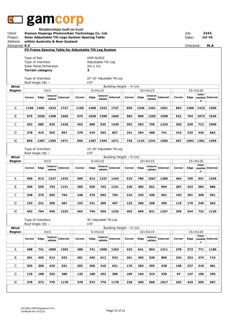
Client: Job:
Project: Date:Address:
Designed: Checked: M.APV Frame Spacing Table for Adjustable Tilt Leg System
Type of Rail HOP-SLR02
Type of Interface Adjustable Tilt Leg
Solar Panel Dimension 2m x 1m
Terrain category 3
Type of Interface 10°-15° Adjustable Tilt Leg
Roof Angle (Φ) – ≤10°
Corner EdgeInterm
ediateInternal Corner Edge
Interm
ediateInternal Corner Edge
Interm
ediateInternal Corner Edge
Inter
mediat
e
Internal
A 1106 1400 1522 1727 1106 1400 1522 1727 955 1346 1461 1651 852 1306 1416 1596
B 675 1030 1398 1669 675 1030 1398 1669 584 890 1205 1598 522 794 1073 1545
C 452 685 925 1420 452 685 925 1420 392 593 799 1224 350 530 713 1090
D 278 419 563 857 278 419 563 857 241 364 488 741 216 325 436 662
W 850 1287 1395 1571 850 1287 1395 1571 735 1124 1341 1506 657 1002 1301 1459
Type of Interface 15°-30° Adjustable Tilt Leg
Roof Angle (Φ) – ≤10°
Corner EdgeInterm
ediateInternal Corner Edge
Interm
ediateInternal Corner Edge
Interm
ediateInternal Corner Edge
Inter
mediat
e
Internal
A 599 913 1237 1443 599 913 1237 1443 519 789 1067 1386 464 705 951 1345
B 369 559 753 1151 369 559 753 1151 320 485 651 994 287 433 582 886
C 248 375 503 764 248 375 503 764 216 325 436 661 193 291 390 591
D 153 231 309 467 153 231 309 467 133 200 268 405 119 179 240 362
W 463 704 950 1325 463 704 950 1325 402 609 821 1257 359 544 732 1120
Type of Interface 30° Adjustable Tilt Leg
Roof Angle (Φ) – ≤10°
Corner EdgeInterm
ediateInternal Corner Edge
Interm
ediateInternal Corner Edge
Interm
ediateInternal Corner Edge
Inter
mediat
e
Internal
A 488 741 1000 1363 488 741 1000 1363 423 641 864 1311 378 573 771 1180
B 301 455 612 932 301 455 612 932 261 395 530 806 234 353 474 719
C 203 306 410 621 203 306 410 621 176 265 355 538 158 237 318 481
D 125 188 252 380 125 188 252 380 109 164 219 330 97 147 196 295
W 378 572 770 1178 378 572 770 1178 328 495 666 1017 293 443 595 907
Wind
Region
Building Height – H (m)
H≤5 5<H≤10 10<H≤15 15<H≤20
Wind
Region
Building Height – H (m)
H≤5 5<H≤10 10<H≤15 15<H≤20
Wind
Region
Building Height – H (m)
H≤5 5<H≤10 10<H≤15 15<H≤20
within Australia & New Zealand
Xiamen Hopergy Photovoltaic Technology Co. Ltd. 2242
Solar Adjustable Tilt Legs System Spacing Table Jul-16
K.Z
ISO 9001:2008 Registered Firm
Certificate No: AU1222 Page 10 of 12
Page 15
PV Frame Spacing Table for Adjustable Tilt Leg System
Type of Rail HOP-SLR02
Type of Interface Adjustable Tilt Leg
Solar Panel Dimension 2m x 1m
Terrain category 3
Type of Interface 30°-60° Adjustable Tilt Leg
Roof Angle (Φ) – ≤10°
Corner EdgeInterm
ediateInternal Corner Edge
Interm
ediateInternal Corner Edge
Interm
ediateInternal Corner Edge
Inter
mediat
e
Internal
A 381 577 777 1190 381 577 777 1190 331 500 673 1027 296 447 601 915
B 236 356 477 725 236 356 477 725 205 309 414 627 183 276 370 561
C 159 239 320 485 159 239 320 485 138 208 278 420 124 186 249 376
D 98 148 197 298 98 148 197 298 85 128 172 258 77 115 154 231
W 295 447 600 914 295 447 600 914 256 387 520 790 230 346 465 705
Type of Interface 30°-60° Adjustable Tilt Leg
Roof Angle (Φ) – 10°-20°
Corner EdgeInterm
ediateInternal Corner Edge
Interm
ediateInternal Corner Edge
Interm
ediateInternal Corner Edge
Inter
mediat
e
Internal
A 599 913 1237 1443 599 913 1237 1443 519 789 1067 1386 464 705 951 1345
B 369 559 753 1151 369 559 753 1151 320 485 651 994 287 433 582 886
C 248 375 503 764 248 375 503 764 216 325 436 661 193 291 390 591
D 153 231 309 467 153 231 309 467 133 200 268 405 119 179 240 362
W 463 704 950 1325 463 704 950 1325 402 609 821 1257 359 544 732 1120
Type of Interface 30°-60° Adjustable Tilt Leg
Roof Angle (Φ) – 20°-30°
Corner EdgeInterm
ediateInternal Corner Edge
Interm
ediateInternal Corner Edge
Interm
ediateInternal Corner Edge
Inter
mediat
e
Internal
A 1106 1400 1522 1727 1106 1400 1522 1727 955 1346 1461 1651 852 1306 1416 1596
B 675 1030 1398 1669 675 1030 1398 1669 584 890 1205 1598 522 794 1073 1545
C 452 685 925 1420 452 685 925 1420 392 593 799 1224 350 530 713 1090
D 278 419 563 857 278 419 563 857 241 364 488 741 216 325 436 662
W 850 1287 1395 1571 850 1287 1395 1571 735 1124 1341 1506 657 1002 1301 1459
Wind
Region
Building Height – H (m)
H≤5 5<H≤10 10<H≤15 15<H≤20
Wind
Region
Building Height – H (m)
H≤5 5<H≤10 10<H≤15 15<H≤20
Wind
Region
Building Height – H (m)
H≤5 5<H≤10 10<H≤15 15<H≤20
ISO 9001:2008 Registered Firm
Certificate No: AU1222 Page 11 of 12
Page 16
General Notes
Note 1 Screws minimum embedment length into timber 35 mm
Note 2 Recommended screws
Note 3 Following components are satisfied to use according to AS1170.2011
Note 4 For adjustable tilting leg,
Maximum back leg angle to horizontal - 90°Minimum back leg angle to horizontal - 30°
Note 5 Refer Figure 5.3 of AS/NZS 1170.2:2011 for definition
of roof zones.
Note 6
HOP-SLR02 Rail HOP-SLR02
Tilt Legs
Fasteners to use
Pine and Hardwood (35mm embedment and
above)M6 (12g) with 10 TPI
Components Part Number Description
Adjustable Tilt Legs Kit (front and back leg)
HOP-SLR02 Rail
Terrain category 3(TC3) refers to numerous closely spaced obstructions having heights
generally from 3 m to 10 m. For example suburban housing or light industrial estates. Refer
clause 4.2.1 of AS/NZS 1170.2-2011 Amdt 3-2013 for definition of Terrain category 3.
Metal Purlins/Battens Fasteners to use
0.55 mm – 1.5 mm M6-11 TPI RoofZips
1.9 mm M6-11 TPI RoofZips OR 12g-14 TPI Teks screws
2.4 mm and Above 12g-24 TPI Teks screws
Wood purlins and Rafter
ISO 9001:2008 Registered Firm
Certificate No: AU1222 Page 12 of 12