ArresterFacts 004 The Externally Gapped Line Arrester (EGLA)
Copyright ArresterWorks 2016 Page 2
The Externally Gapped Line Arrester (EGLA)
Jonathan Woodworth ArresterWorks
A lightning proof transmission line has been attainable since the early 1990s, when the polymer housed transmission line arrester was first introduced by Hubbell Power Systems. According to IEEE Std. 1410 [4] and IEEE Std. 1243[5], the installation of arresters on every phase of every tower of a shielded line will result in zero lightning induced flashovers of insulators. This is essentially a lightning proof line; however, line designers have not adopted this strategy for improving line performance for numerous reasons. The most cited reason for not applying arresters on transmission lines for lightning protection is that the arresters themselves are a potential reliability reducing factor and would require too much maintenance. The dominant line arrester that has been used for the last 20 years is the non-gapped line arrester which has demonstrated that this is not a real concern. The NGLA is, in fact, highly reliable and only occasionally have there been failures. Despite this, it is clear that another approach to the lightning proof concept is necessary to reduce the concerns of line designers. To that end, the EGLA and its unique characteristics are discussed in detail in this paper in an effort to increase the confidence level in line protection with arresters.
The EGLA Concept The EGLA is an arrester design that dates back to the earliest stages of surge protection on power lines. In later years it became an internal gap, but performed the same basic function. The reason for this long history is that a simple air gap has excellent capabilities when used to withstand voltage and predictable breakdown at a very specific voltage level. It is no accident that arrester designs over the years have continued to use this device. Even today there are millions of arresters in service that are using an air gap to hold off the line voltage until a surge appears. In the presence of a surge they sparkover and assist in the task of protecting equipment on power lines.
When highly nonlinear metal oxide varistors (MOV) are connected in series with the age-old gap, the combination takes on very unique features not
previously seen in gapped arresters of earlier designs. It is these unique and repeatable characteristics that make the externally gapped MOV arrester the ultimate in distribution and transmission line protection.
The EGLA as shown in Figure 1 has been applied in Japan, Europe and Mexico as an IEC certified device for a number of years. The IEC type EGLA differs in that it is designed to protect lines from lightning only. This lightning only application is achieved by increasing the gap spacing to a level that will not sparkover in the presence of switching surges. For systems above 230kV, the IEC type EGLA does not need larger varistors to handle the energy associated with switching surges. The IEC type EGLA is characterized by a larger gap section and smaller tolerance in the gap dimension than the EGLA discussed in this paper. The IEC type EGLA is also an arrester recognized in the IEC community and has a test standard specifically written for it [6].
Note the EGLA is referred to as a line arrester, which means it is designed to be applied on lines to eliminate insulator flashovers and not for the protection of sensitive oil insulated equipment such as transformers. Because it is only used to eliminate insulator flashover,
Figure 1: Externally Gapped Line Arrester mounted on
a 115kV transmission line
ArresterFacts 004 The Externally Gapped Line Arrester (EGLA)
Copyright ArresterWorks 2016 Page 3
the front-of-wave sparkover of this type of arrester is irrelevant and not an application issue. Figure 2 contrasts the front-of-wave characteristics of various types of arresters.
How it Works The well-coordinated gap and varistor work in conjunction to turn the arrester on and off. In spite of the high sparkover characteristic of the gap, it is more than adequate for protecting the self-restoring insulation of line insulators, whether on a distribution system or a 500kV transmission system.
When a lightning surge from a direct strike travels along the line and reaches a standard insulator not protected by an arrester, it will flashover the insulator. The lightning induced flashover will cause a fault on the power system.
A fault can be prevented by using an EGLA to protect the insulator. Lightning is directed through the arrester, which turns on immediately because the voltage is above the sparkover of the gap and turn-on point of the varistors. Immediately following the lightning charge transfer, the varistors terminate all current flow and there is no power frequency follow current or fault.
The robustness of line insulator withstand characteristics, as well as its self-restoring capability, make the EGLA a perfect candidate for its protection.
The Gap Function and Design Criteria The gap of all externally gapped arresters is a critical component in determining the turn on voltage of the arrester. It is important that the gap of the EGLA be large enough to withstand typical voltage swings during temporary overvoltage events, but small enough that it will always sparkover before the protected insulator flashes over. Figure 3 is a graphic that outlines considerations used to determine the gap setting of the EGLA that sparks over for both switching and lightning surges.
The minimum acceptable gap setting of an EGLA is determined by three factors: the system voltage, expected temporary overvoltage levels (TOV), and a safety factor. The maximum acceptable gap is set by two factors, the CFO of the protected system plus safety factors.
Minimum Gap Spacing Rationale and Equations For the EGLA that is capable of both switching and lightning, the gap needs to be spaced so that no AC power frequency voltage swing will spark it over. (See Annex A for Lightning only EGLA) To achieve this withstand level, the gap is set to withstand the maximum expected temporary overvoltage level plus 20% more for a safety margin. The maximum temporary overvoltage of a system can be determined accurately with transient modeling, or it can be estimated with prior knowledge of the source transformer grounding configurations.
This procedure is similar to the MCOV rating selection of standard MOV type arresters. TOV factors recommended for this procedure are presented in the table below.
Because there is no current flow through the arrester prior to flashover of the gap, the arrester does not influence the gap flashover voltage. The minimum AC Power frequency voltage that EGLA gap will flashover is:
𝑪𝑭𝑶𝒑𝒇 = (𝑬𝒔𝒚𝒔
𝟏.𝟕𝟑) 𝑻𝑶𝑽𝒇𝒂𝒄𝒕𝒐𝒓 × 𝑺𝑭𝟏 (Eq 1)
Where: CFOpf Min power frequency flashover voltage (kV
rms) Esys Max line to line voltage (kV rms)
Figure 2: Front-of-Wave characteristics of various arrester types
ArresterFacts 004 The Externally Gapped Line Arrester (EGLA)
Copyright ArresterWorks 2016 Page 4
TOVfactor TOV factor based on Table 1 SF1 Safety factor (typically 1.2) The minimum gap spacing is then set from the minimum critical flashover voltage as determined in Eq 1.
𝑺𝒎𝒊𝒏 = 𝟑𝟗. 𝟑𝟕 [𝒆
𝑪𝑭𝑶𝒑𝒇𝟕𝟓𝟎
− 𝟏
.𝟓𝟓]
.𝟖𝟑𝟑
(Eq 2)
Where: Smin gap spacing in inches Note: This applies for Gaps <79” (for spacing >79” a gap factor is used) [1] [2]
Maximum Gap Spacing Rationale and Equations The maximum gap spacing is set so there is little risk that the insulator will flashover during a lightning surge. In order to achieve this, the CFO of the insulator being protected must be known and the CFO of the gap set at a safe level below the CFOins. The relationship of the CFOgap and the Insulator CFOgap is shown in Fig 3. The minimum Margin of Protection is defined as 𝑴𝒊𝒏𝑴𝑶𝑷 = 𝑮𝒂𝒑𝑪𝑭𝑶𝟗𝟎 ≤ 𝑰𝒏𝒔𝑪𝑭𝑶𝟏𝟎 (Eq 3) Where: - Minmop is the minimum margin of protection - GapCFO90 is the voltage level that represents a 90%
probability of gap flashover. - InsCFO10 is the voltage level that represents a 10%
probability of insulator flashover. The recommended value for Gap CFO90 is 7.5% above gap CFO. The recommended value for Insulator CFO10 is 7.5% below the insulator CFO. [5 –section 8.4]
Circuit Type TOV Factor
4 wire solid ground 1.25 -1.35
3 wire grounded at source 1.4
3 wire impedance grounded 1.5 - 1.73
3 wire delta 1.73
Table 1: TOV factors for various neutral configurations
Figure 3: A graphic representation of the gap spacing rational.
ArresterFacts 004 The Externally Gapped Line Arrester (EGLA)
Copyright ArresterWorks 2016 Page 5
Given the above relationship of Max Gap CFO, once the CFO of the insulator is known, the Gap CFO can be calculated as 85% of Insulator CFO to meet the Minimum Margin of Protection. It is a generally accepted fact that the impulse breakdown voltage of air is 560kV/ft or 15kV/inch at STP. Eq 3 then describes the relationship of Gap spacing in inches and Gap CFO
𝑺𝒎𝒂𝒙 =𝑪𝑭𝑶𝑰𝒏𝒔 × .𝟖𝟓
𝟏𝟓𝒌𝑽 ×𝑲 (Eq 3)
Where: Smax is the maximum Gap spacing in inches CFOins CFO of insulator in kV peak Vbreakdown Pos Impulse breakdown voltage of Air which is
accepted as 15kV/inch at STP K Gap factor (1 for rod to plane gaps)
Other Gap Spacing Considerations Fortunately, if a faster surge arrives at the arrester/insulator, both devices will flashover at higher voltages, so once the spacing is set for a standard wave, it will work for faster waves.
If the installation is applied at higher altitudes, the gap spacing will increase as a function of air pressure.
If the electrodes or the arrester can move relative to each other, a second safety factor must be factored in to the equation to account for this movement.
The gap may be affected by environmental conditions, but so is the insulator in parallel with the arrester. Again fortunately if the gap is set to flashover before the protected insulator, it will remain so in most weather conditions. If the parallel insulator is affected by
pollution so severely that it flashes over at power frequency, the arrester cannot affect this or protect against this.
Lead Management Considerations As with all transmission line arresters, lead management is a significant consideration. In the case of the EGLA the electrodes are generally shorter than leads and electrode management is less of a challenge than leads of an NGLA.
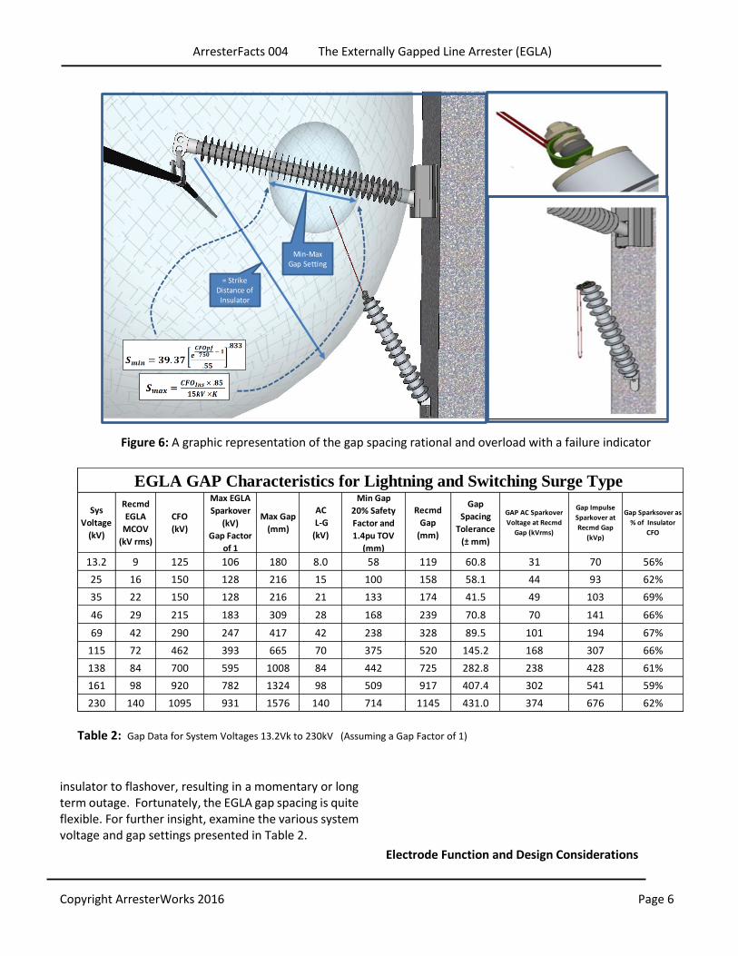
Arrester Overload Considerations In arrester overload situations, the optimum configuration would be to use a disconnector or a failure indicator, as shown in Figure 5 and 6.
Effect of Incorrect Gap Spacing Incorrect gap spacing may cause an array of problems. These issues vary depending on if the spacing was below the minimum level or above the maximum level. If the gap spacing is installed below the minimum level, the risk of flashover during a temporary overvoltage event increases. This could lead to arrester damage or failure. If the gap is installed with its separation above the maximum recommended level, it may allow the insulator to flashover before the gap sparks over. While this will not cause an arrester failure, it may allow the
Figure 4: Altitude and gap spacing relationship
Figure 5 EGLA mounted to result in full CFO recovery if
overloaded This configuration will move the electrode after the
overload so that the insulator CFO is fully recovered
ArresterFacts 004 The Externally Gapped Line Arrester (EGLA)
Copyright ArresterWorks 2016 Page 6
insulator to flashover, resulting in a momentary or long term outage. Fortunately, the EGLA gap spacing is quite flexible. For further insight, examine the various system voltage and gap settings presented in Table 2.
Electrode Function and Design Considerations
Figure 6: A graphic representation of the gap spacing rational and overload with a failure indicator
= Strike Distance of
Insulator
Min-Max Gap Setting
Table 2: Gap Data for System Voltages 13.2Vk to 230kV (Assuming a Gap Factor of 1)
EGLA GAP Characteristics for Lightning and Switching Surge Type
Sys
Voltage
(kV)
Recmd
Gap
(mm)
Gap
Spacing
Tolerance
(± mm)
Min Gap
20% Safety
Factor and
1.4pu TOV
(mm)
AC
L-G
(kV)
Max Gap
(mm)
Max EGLA
Sparkover
(kV)
Gap Factor
of 1
Recmd
EGLA
MCOV
(kV rms)
ArresterFacts 004 The Externally Gapped Line Arrester (EGLA)
Copyright ArresterWorks 2016 Page 7
Though the electrodes may seem like a simple
component of this arrester, they are definitely not so.
The EGLA electrodes provide the following functions: 1. Creates a durable location on the arrester or phase
conductor for the arc, caused by the surge, to land upon without damage.
2. Allows for adjustability of the gap spacing. 3. Offers a surface that is equidistant from the opposite
electrode for various insulator or arrester motion. 4. Produces a shape that has consistent and
predictable flashover 5. Generates full CFO to the system upon failure if the
electrode and EGLA is equipped with a disconnector, as shown in Figure 5&6.
Note that every EGLA needs at least two electrodes. Sometimes the second electrode can be part of the existing system and not an actual part of the arrester.
The electrodes must meet numerous requirements to provide the aforementioned functions. These requirements are as follows:
1. Mechanical strength 2. Non-aging finish 3. Shape conducive to the system voltage and the
potential swinging of the arrester or phase conductor. 4. Conductivity adequate for surges but not power
frequency current 5. Acceptable failure mode 6. Wind withstand
Electrode Mechanical Strength The mechanical strength requirement stems from the need to remain in the initial configuration for the life of the arrester. At a minimum, the electrode needs to be self-supporting. During its life, the electrode should be able to sustain events that will stress the material, such as bird perching, wind, and ice. A flexible electrode is acceptable as long as it does not take on a permanent reshape, which would allow for a change in the original spacing.
Electrode Finish and Material
It is important that the material and surface finish not oxidize with time. If the gap oxidizes radically, it could change the sparkover voltage. It is recommended that stainless steel, brass, or aluminum be used for the electrodes. Galvanized steel is an option, but the point where the arc impinges can become rusty. The electrode needs to be a conductor, but its conductivity is not important. If it is a poor grade conductor but meets all other requirements, it is acceptable.
Phase Electrode Consideration As stated earlier, it is not always necessary to have an electrode on the phase side of the gap. If the phase electrode is a large part of the insulator fitting, as seen in Figure 4, then it is obvious that nothing more is needed. However though not necessary, it may be prudent to use a rod gap at both ends of the gap to make flashover more predictable.
It is important to note that the current through the EGLA is restricted to the surge current. If a conductor has armor covering the conductor near the insulators to handle lightning flashovers, it may not be necessary to
make any other accommodations. Always ask the basic question: “If there was no arrester located at an insulator, how would a flashover and power arc be accommodated?” The answer will assist in the decision about a phase electrode.
Series Varistor Unit (SVU) Considerations
Figure 6 By superimposing the AC voltage on the VI curve of the SVU,
the relationship of the two can be illustrated.
ArresterFacts 004 The Externally Gapped Line Arrester (EGLA)
Copyright ArresterWorks 2016 Page 8
The varistor component, also known as series varistor
unit or SVU, is comprised of non-linear MOV disks. The
SVU has one basic function in this arrester, and that is
to limit the surge current. In effect, it terminates the
surge event as the surge drops in voltage. The SVU is
for all practical purposes a non-gapped arrester.
Voltage Rating of SVU When selecting the voltage rating of the SVU, the most
important consideration is the maximum line to ground
voltage the system will experience. As demonstrated in
Figure 5, the turn on level of the SVU is set just above
the peak line to ground voltage of the system. As a
general rule of thumb, the 1mA Vref of the SVU must
equal or exceed the peak line to ground voltage.
The discharge voltage of the EGLA is the sum of the
voltage across the gaps, the varistors, and the leads. In
most cases, this voltage is lower than a standard
arrester and can easily clamp the voltage well below
the CFO of the protected insulator.
Energy Considerations of the SVU There are three fundamental system protection schemes that need to be taken into account when determining the energy handling capability of an EGLA arrester: shielded systems below 230 kV, shielded systems 230 kV and above, and unshielded systems.
Shielded systems below 230kV For shielded systems below 230kV that are not equipped with large cap banks, the energy handling requirement from the lightning surge usually exceeds the switching surge requirements. Distribution class arresters are most commonly used for this application.
Shielded systems above 230kV For this system type, the switching surge energy handling capability needs to be considered. For longer lines, the switching surge capability can exceed the lightning charge transfer requirements. A basic system study or rule of thumb equations from C62.11 can be used to make the determinations. It is quite possible that
station class disks will need to be used for this application.
Unshielded Systems For distribution systems that are typically unshielded, a standard distribution arrester will suffice for the SVU of an EGLA. For higher voltage systems where current sharing between arresters is an option, higher charge transfer disks may need to be used for the SVU.
SVU Housing and Leakage Distance Because the SVU does not have a voltage stress along its surface, it does not need the long term power frequency withstand capability that is required of normal arresters. Normally arresters have a voltage stress along their surface for the lifetime of the arrester. This stress demands that the arrester have a longer surface distance than the internal components normally require. The only time the SVU experiences a voltage stress is during a surge clamping event; at all other times the voltage difference between the two ends of the SVU is virtually zero.
Because there is no voltage stress along the length of the SVU during its life time, the leakage distance can be equal to the strike distance for most applications. For more potentially contaminated environments, the leakage distance may need to be a small percentage longer. Less material in this case is an area of opportunity to make the arrester a more sustainable product.
Besides providing leakage distance, the housing is also the major environmental seal of the SVU. Moisture ingress in the presence of voltage stress is a major challenge for the housing of an SVU. Even though the AC stress is minimal, the need for a very well-sealed SVU is paramount.
Wildlife Guarding For arresters applied above 46kV, the SVU becomes long enough to not be concerned about animals stretching from ground to phase electrode. However, animals can get across the gap and the resulting leakage current will likely not be good for the animal but not cause an outage. It is not likely that the arrester will fail, because the current is limited by the varistors.
ArresterFacts 004 The Externally Gapped Line Arrester (EGLA)
Copyright ArresterWorks 2016 Page 9
EGLA Arrester Voltage Rating Considerations The voltage ratings of NGLA arresters can be confusing to the novice because the standards and data sheets for ungapped arresters routinely discuss two ratings: the MCOV and the Duty Cycle Rating. The only rating that matters to users, however, is the MCOV or Uc in the IEC area.
For the EGLA, the only voltage rating that matters is the MCOV. This is the maximum voltage the arrester can withstand over its life and still withstand TOV events as they arise. This level is claimed by the manufacturer and has been verified in the operating duty test.
An 8.4kV MCOV of an EGLA is the equivalent of an 8.4kV MCOV ungapped arrester. The 70kV MCOV rating of an EGLA is exactly the same as the 70kV MCOV rating of an ungapped arrester.
Benefits The benefits of this type of arrester are numerous. Because of the gap, there are zero losses and there is no chance of a long term fault because of the arrester. The arrester construction is more sustainable to the environment due to less material. The life of the arrester is nearly infinite due to the minimal AC voltage stress on the SVU. A subtler benefit is the fact that less rubber can be used on the housing because leakage distance is optional. Also, with no voltage applied to the varistor after an impulse, the varistors do not need such sophisticated formulations and processing. Summary With the use of this type of arrester on transmission lines and distribution lines two issues can be resolved, a lightning proof line can be achieved and the maintenance and reliability issues that linger with line designers in regard to the use of arresters should be resolved. Acknowledgements
Many thanks for significant input from project partner
Ceralink Inc. of Rensselaer NY. A special thanks to John
Williamson of J. Williamson Engineering Inc for his helpful
comments. Also a special thanks to Dan Ward of Dominion
Virginia Power for his input and critical review.
REFERENCES
Books: [1] Hileman, A.R., Insulation Coordination for Power Systems, Marcel Dekker, Inc., New York, 1999, ISBN 0-8247-9957-7. , pg 79 Eq 57
Standards: [2] IEC Standard 60071-2- 1996 “Insulation co-ordination - Part 2:
Application guide” Annex G1
[3] IEEE Std. 1410 “IEEE Guide for Improving the Lightning Performance of Electric Power Overhead Distribution Lines”
[4] IEEE Std. 1243” IEEE Guide for Improving the Lightning Performance
of Transmission Lines” [5] IEC Standard 60099-8 “Surge arresters - Part 8: Metal-oxide surge
arresters with external series gap (EGLA) for overhead transmission and
distribution lines of a.c. systems above 1 kV”
Also See EGLA Gap Calculator at ArresterWorks.com
EGLA Gap Calculator by ArresterWorks
Application Altitiude 0 ft
Insulator CFO Per Catalogs
(At sea level)500 kV 21.5 inches
Altitude Correction Factor 1.000 6.8 +/- inches
Insulator CFO At Altitude 500 kV 23.9 inches 358.3
4.4 +/- inches
527.8 mm
Max Gap (at altitude) 28.3 inches 166.4 +/- mm
Max Gap (at altitude) 720 mm 585.1 mm
109.0 +/- mm
System Voltage Line-Line 115 kV rms System Voltage Line-Line 115 kV rms
ArresterFacts 004 The Externally Gapped Line Arrester (EGLA)
Copyright ArresterWorks 2016 Page 10
Annex A Calculating the Minimum Gap distance for EGLA used for lightning surges only The EGLA available as certified to IEC 60099-8 is designed and tested to only respond to lightning surges for all voltage ratings. This means the gap is set wide enough to not allow any sparkover for switching surges. The value of the minimum gap setting is thus set based on the expected maximum switching surge the arrester is expected to see. The equation A1 is used for this calculation.
𝑮 = 𝟑𝟗. 𝟑𝟕[𝒆(𝑺𝑺/𝟏𝟎𝟖𝟎) − 𝟏
. 𝟒𝟔]
Where G = Gap Distance in inches SS = Maximum Expected in Switching Surge in kV The resulting characteristics are given in Table A1
Table A1: Gap Data for System Voltages 13.2Vk to 230kV (Assuming a Gap Factor of 1) for EGLA designed to 60099-8


![Contour Optimization of a Pin Insulator Using Neural Networki-rep.emu.edu.tr:8080/jspui/bitstream/11129/1747/1/AimuaFidelis.pdf · From [2], it is noted that flashover do occur along](https://static.documents.pub/doc/80x56/60a2ceb8cf2ef010310fee1b/contour-optimization-of-a-pin-insulator-using-neural-networki-repemuedutr8080jspuibitstream1112917471.jpg)


