Page 1
GARN® WHS Electric Heating Package Manual ©DECTRA CORPORATION - May 2016 (Supersedes September 2015 edition)
1
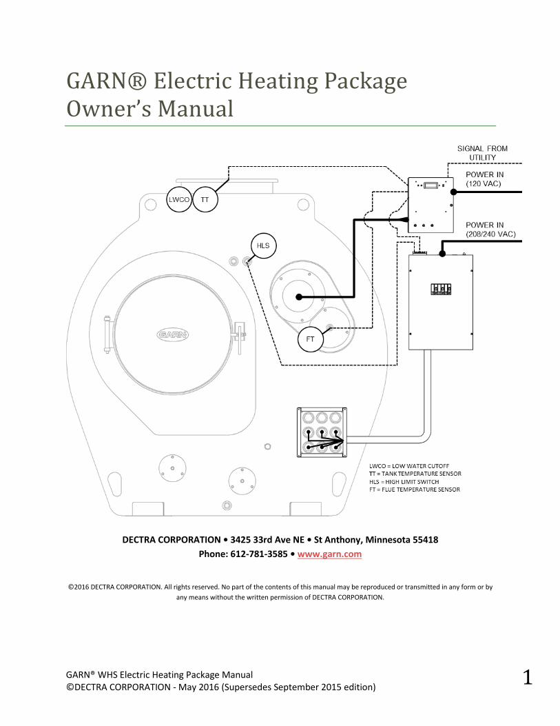
GARN® Electric Heating Package Owner’s Manual
DECTRA CORPORATION • 3425 33rd Ave NE • St Anthony, Minnesota 55418
Phone: 612-781-3585 • www.garn.com
©2016 DECTRA CORPORATION. All rights reserved. No part of the contents of this manual may be reproduced or transmitted in any form or by
any means without the written permission of DECTRA CORPORATION.
Page 2
GARN® WHS Electric Heating Package Manual ©DECTRA CORPORATION - May 2016 (Supersedes September 2015 edition)
2
OWNER’S MANUAL FOR THE GARN® WHS ELECTRIC HEATING PACKAGE
Thank you for purchasing GARN® equipment. Carefully read this manual. It contains instructions about how to
install, operate, and maintain your GARN® WHS Electric Heating Package. Please compare your packing list with
the delivered items. Contact your dealer, DECTRA CORPORATION, and shipper immediately if any items are missing
or damaged.
TABLE OF CONTENTS
A. PURPOSE OF THIS MANUAL: .......................................................................................................................... 3
B. EQUIPMENT, COMPONENTS, AND CONTROLS OVERVIEW: ............................................................................ 3
AVAILABLE HEATING PACKAGE SIZES: ....................................................................................................................... 3
WHAT IS PROVIDED WITH THE ELECTRIC HEATING PACKAGE?: ................................................................................. 3
SCHEMATIC DIAGRAM OF EQUIPMENT, COMPONENTS, AND CONTROLS: ............................................................... 5
C. CODES, INSURANCE, AND SAFETY SYMBOLS .................................................................................................. 6
D. INSTALLATION ............................................................................................................................................... 7
GROUNDING .............................................................................................................................................................. 7
PREVENTING ELECTROLYSIS CORROSION REQUIRES PROPER GROUNDING AND ELECTRIC ISOLATION ............... 7
ELECTRIC ELEMENTS .................................................................................................................................................. 8
ELECTRIC ELEMENT BOX ............................................................................................................................................ 8
SINGLE SEQUENCER ................................................................................................................................................. 11
DUAL SEQUENCERS ................................................................................................................................................. 12
E. OPERATION: ................................................................................................................................................ 13
WOOD OR ELECTRIC/WOOD OPERATION ................................................................................................................ 13
TEMPERATURE SETPOINT ADJUSTMENT ................................................................................................................. 14
DIAL SWITCH POSITIONS ..................................................................................................................................... 15
OUTDOOR RESET CURVE (USED WITH DIAL POSITION 1) ................................................................................... 16
F. WIRING DIAGRAMS: .................................................................................................................................... 17
WHS/ETS DIGITAL CONTROLLER – REV A ................................................................................................................. 17
WHS/ETS DIGITAL CONTROLLER – REV C ................................................................................................................. 18
SEQUENCER – 16.5 KW............................................................................................................................................. 19
SEQUENCER – 33.0 KW............................................................................................................................................. 20
SEQUENCER – 49.5 KW............................................................................................................................................. 21
IDENTIFYING YOUR BOARD REVISION ..................................................................................................................... 22
IDENTIFYING YOUR CHIP REVISION ......................................................................................................................... 22
CONTROLLER TO SEQUENCER WIRING – BOARD REV: UPC7115-A .......................................................................... 23
CONTROLLER TO SEQUENCER WIRING – BOARD REV: UPC7115-C .......................................................................... 24
CONTROLLER TO OFF-PEAK METER WIRING ............................................................................................................ 25
USING AN AQUASTAT TO SET A CUSTOM DEADBAND AND SETPOINT .................................................................... 27
G. WARRANTY ................................................................................................................................................. 28
Page 3
GARN® WHS Electric Heating Package Manual ©DECTRA CORPORATION - May 2016 (Supersedes September 2015 edition)
3
A. PURPOSE OF THIS MANUAL:
This manual is intended to be a reference for both the owner and the electrician/installer of the GARN
Electric Heating Package. It provides the following information:
Overview of operation and control logic
Wiring diagrams and control schematics
Answers to commonly asked questions
GARN has made off-peak heating equipment since the early 1980’s. Off-peak heating works well with
GARN wood equipment because the thermal storage is already built into the unit. Although the specific
configurations of the GARN electric heating controls and packaging has been revised over the years, the
operational philosophy and the way in which the controls physically interact with the utility has
remained nearly unchanged. That means, that this manual can be applied to virtually any electric
heating equipment system GARN has ever produced. But, the manual is specifically tailored towards the
most recent revisions of controls and packaging.
B. EQUIPMENT, COMPONENTS, AND CONTROLS OVERVIEW:
Every GARN® WHS is shipped with threaded electric element flanges in the lower-right corner of the
front head/face of the unit (on the WHS-3200, the flanges are located on the rear head of the unit). The
flanges provide the opportunity to purchase the electric heating package and turn the GARN® WHS unit
into an electric heating system. Electric heating can be used in conjunction with wood heating to
provide a dual-fuel heating system. There are 3 electric heating package sizes to choose from. The
correct size for your application depends on the utility/coop off-peak electric program, heating load, and
GARN WHS unit size.
AVAILABLE HEATING PACKAGE SIZES:
Electric Heating Package Size Number of Electric Elements
16.5 kW 3
33.0 kW 6
49.5 kW 9
WHAT IS PROVIDED WITH THE ELECTRIC HEATING PACKAGE?:
The Complete GARN Electric Heating Package comes standard with the following components:
Electric Elements (3, 6, or 9 depending on heating package size selected)
O-rings for elements
Electric Element Junction Box
Electric Element Junction Box Face Gasket
Electric Element Junction Box Cover, Label, and Fasteners
Element Sequencer (powers the elements on one-at-a-time)
High Limit Switch
Newest available Processor Chip for the Digital Controller
Page 4
GARN® WHS Electric Heating Package Manual ©DECTRA CORPORATION - May 2016 (Supersedes September 2015 edition)
4
There are 4 main components that work together to create the GARN Electric Heating Package:
1. WHS/ETS digital controller (supplied by GARN)
The digital controller receives a signal from the utility indicating that off-peak power is
available and then sends a signal to the sequencer to turn on the elements if certain criteria
are met. The name “GARN WHS/ETS” on the digital controller label is derived from two
acronyms: “Wood Heat Storage” and “Electric Thermal Storage”
2. Sequencer (supplied by GARN)
The sequencer turns the elements on one after another to provide a gradual power-up. The
sequencer is composed of a series of breakers and time-delay relays. Power to the
sequencer is supplied from an electrical panel (or directly from a utilty meter) and is
connected to the breakers inside of the sequencer. Then a pair of conductors is wired from
the output contacts of the time delay relays to each element. One time-delay relay serves
one element.
A single sequencer can serve up to 33.0 kW. In the case of the 49.5 kW package, 2
sequencers are provided and both must be field installed and wired.
Two (2) sequencers are provided with the 49.5 kW package.
3. Electric Elements and Element Box (supplied by GARN)
The Electric Elements are made of Incoloy®, a high-grade nickel and chromium alloy. The
electric resistive elements are embedded in a lime and sand mixture inside of the Incoloy
casing. The elements are Low-Watt Density which provides the safest and most robust
option for heating with electricity.
4. Power Supply for Electric Elements (from Electric Panel or directly from a Utility meter)
(supplied by others – usually the utility)
The power source for the electric elements must come from a building electrical panel or
directly from a utility meter. The power is supplied to the sequencer, and the sequencer
then distributes the power to the elements. If power is being supplied by a panel, then the
panel must be properly sized and rated for the power draw of the electric heating package
being installed.
The specific type of utility meter can vary based on the utility supplying the meter
and the programs they offer: Smart Meter, Time-of-Day Meter, Off-Peak Meter,
etc.
Page 5
GARN® WHS Electric Heating Package Manual ©DECTRA CORPORATION - May 2016 (Supersedes September 2015 edition)
5
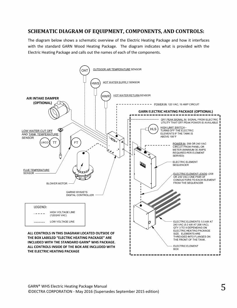
SCHEMATIC DIAGRAM OF EQUIPMENT, COMPONENTS, AND CONTROLS:
The diagram below shows a schematic overview of the Electric Heating Package and how it interfaces
with the standard GARN Wood Heating Package. The diagram indicates what is provided with the
Electric Heating Package and calls out the names of each of the components.
Page 6
GARN® WHS Electric Heating Package Manual ©DECTRA CORPORATION - May 2016 (Supersedes September 2015 edition)
6
C. CODES, INSURANCE, AND SAFETY SYMBOLS
The GARN® WHS Wood Heat Storage is listed by ITS/Warnock Hersey Testing Laboratory, Madison,
Wisconsin according to ANSI/UL-391, UL-726 and CAN/USA B366.1-11. Install the
GARN® ETS Electric Thermal Storage according to this manual, on-line technical
bulletins, Federal, State and local codes, and your insurance underwriter’s guidelines.
The GARN® unit, all related heating equipment (including pumps, piping, fan coils, hot
water baseboard, radiant floor heating systems, etc), and all electrical equipment
(including power wiring, controls, control wiring, back up electric heating, etc) must be installed by a
qualified installer or licensed personnel in strict compliance with all Federal, State and local codes.
THE WIRING AND INSTALLATION OF THE GARN® ETS ELECTRIC HEATING
PACKAGE SHALL BE COMPLETED BY A CURRENTLY LICENSED ELECTRICIAN IN
FULL COMPLIANCE WITH ALL SECTIONS OF NEC, FEDERAL, STATE AND LOCAL
CODES. The installer must keep in mind the following:
All electrical equipment, devices and wiring installed with the GARN® unit must be UL/CSA
listed. The installer is to supply and install all code required electrical overcurrent and
disconnect devices.
All wiring, controls, relays, transformers, enclosures, etc shall be UL/CSA listed and comply with
NEC Class 1 600 V requirements.
As a minimum all power wiring shall be 10 ga 600 VAC 105 C, tinned plated stranded copper.
All “female crimp connectors” shall be high temperature UL/CSA listed for electric heating
equipment (such as Hollingsworth SO9300) and shall be installed utilizing the correct crimp tool.
DO NOT USE standard crimp connectors as they will fail due to overheating.
All wiring shall be in metallic conduit, sized per NEC with proper de-rating (for temperature,
environmental conditions, etc)
This manual is intended to comply with NEMA Z535.6-2006 (the standard for Product Safety Information
in Product Manuals, Instructions, and Other Collateral Material). Throughout the manual, a series of
safety symbols are intended to call to attention the following types of information:
A notice provides a piece of information to make a procedure/process easier or
clearer.
A caution emphasizes where equipment damage might occur. Personal injury is
not likely.
A warning emphasizes areas where personal injury or death may occur but is not
likely. Property or equipment damage is likely.
A danger emphasizes areas or procedures where death, serious injury, or property
damage is likely if not strictly followed.
Page 7
GARN® WHS Electric Heating Package Manual ©DECTRA CORPORATION - May 2016 (Supersedes September 2015 edition)
7
D. INSTALLATION
GROUNDING
THE STEEL TANK (GARN WHS UNIT) MUST BE GROUNDED TO THE SAME POWER
PANEL THAT SERVES THE ELECTRIC ELEMENTS. DEATH OR SEVERE INJURY MAY
RESULT IF THE TANK IS NOT PROPERLTY GROUNDED.
PREVENTING ELECTROLYSIS CORROSION REQUIRES PROPER GROUNDING AND
ELECTRIC ISOLATION
GARN units no longer are supplied magnesium anode rods. The reason for this is many-fold; for further
reading and explanation, please visit our Technical Service Bulletin page at:
http://www.garn.com/technical-service-bulletins/
In addition, it is no longer recommended to ground the GARN tank with an independent ground rod.
Specific grounding procedures must be followed.
1. Ground the GARN tank by attaching a properly sized ground wire to the steel mounting stud of
the electric element box.
2. The grounding wire must go back to the panel (or ground rod – if directly connected to a utility
meter) of the power service serving the sequencer.
DO NOT GROUND THE TANK TO ANY LOCATION OTHER THAN TO THE SAME
LOCATION AS THE POWER SOURCE FOR THE ELECTRIC HEATING ELEMENTS.
For further grounding details and illustrations on how to properly ground a GARN unit with electric
heating elements, see the section of the GARN WHS ELECTRIC ISOLATION AND PROPER GROUNDING
Owners Manual at: http://www.garn.com/garn-whs-manuals/
Page 8
GARN® WHS Electric Heating Package Manual ©DECTRA CORPORATION - May 2016
8
ELECTRIC ELEMENTS
Electric resistance heating elements are rated for 240 VAC or 208 VAC. Power to each element must be
supplied by a UL/CSA listed individual two-pole breaker with a common trip.
1.) Mount the electric heating elements in the 1" NPT fittings in the element box. Each element has
an O-ring for proper sealing into its threaded plug. In addition, use Teflon tape to seal the
threads of the elements.
DO NOT USE PIPE DOPE COMPOUNDS ON THE TREADS WHEN INSTALLING THE
ELECTRIC ELEMENTS. The pipe dope lubricates the o-rings and may cause them to
dislodge, which may cause a leak.
2.) Install the elements in the lowest fittings possible to maximize storage. Plug any unused fittings
with 1" NPT plugs (use pipe dope or teflon tape to seal).
ONLY CONNECT STEEL CONDUIT TO THE ELEMENT BOX AS IT MAY REACH
TEMPERATURES IN EXCESS OF 200°F.
3.) Fill the tank with enough water to cover the elements and test for leaks.
ONLY OPERATE THE ELECTRIC ELEMENTS WHEN SUBMERGED IN WATER. If they
are turned on out of water they may burn out and require replacement.
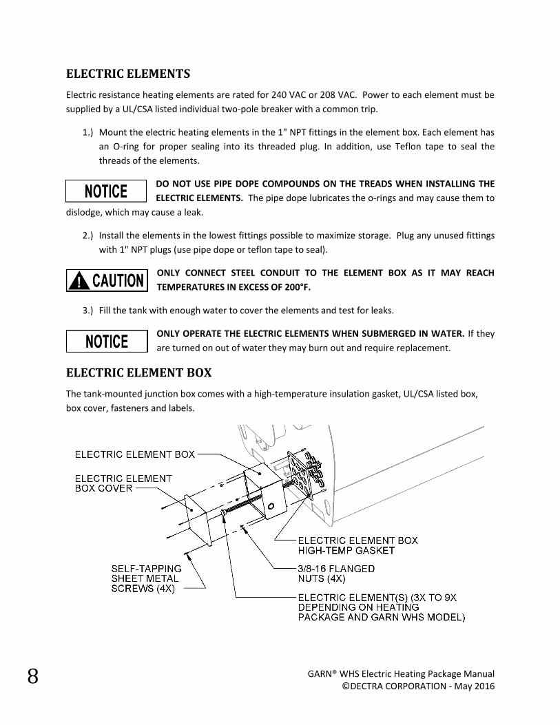
ELECTRIC ELEMENT BOX
The tank-mounted junction box comes with a high-temperature insulation gasket, UL/CSA listed box,
box cover, fasteners and labels.
Page 9
GARN® WHS Electric Heating Package Manual ©DECTRA CORPORATION - May 2016 (Supersedes September 2015 edition)
9
1) Follow the installation instructions in this manual for Installing the Electric Elements. Ensure
that electric elements or 1’NPT plugs are installed and test for leaks.
2) Place insulation pad over the bolts extruding from the tank.
3) Align the junction box with the bolts and push against the insulation gasket.
4) With the nuts provided, tighten the box against the gasket until the gasket compresses slightly.
Page 10
GARN® WHS Electric Heating Package Manual ©DECTRA CORPORATION - May 2016
10
5) Affix the cover after leak testing and electrical installation.
The label on the cover of the Element Box contains information about field wiring
and safety notes. Follow the instructions on the label.
Page 11
GARN® WHS Electric Heating Package Manual ©DECTRA CORPORATION - May 2016 (Supersedes September 2015 edition)
11
SINGLE SEQUENCER
Mount the sequencer in close proximity to the digital controller and electric element box. Follow best
practices for wiring and mounting the boxes. The intent of the following schematic is to give a general
overview of the wiring involved. Refer to the Wiring Diagrams section of this manual and to the labeling
on the controller and sequencer. All wiring should be performed by a licensed electrician.
Page 12
GARN® WHS Electric Heating Package Manual ©DECTRA CORPORATION - May 2016
12
DUAL SEQUENCERS
When connecting the 49.5 kW electric heating package, two sequencers are required. A metal conduit
must be run from each sequencer to the electric element box. If needed, additional knockouts can be
made into the electric element box using a knockout punch.
Page 13
GARN® WHS Electric Heating Package Manual ©DECTRA CORPORATION - May 2016 (Supersedes September 2015 edition)
13
E. OPERATION:
WOOD OR ELECTRIC/WOOD OPERATION
The digital controller can operate in Wood mode and Electric/Wood mode. In the Wood mode, the
controller allows the operator to fire the GARN unit with wood and will NOT turn the electric elements
on to regulate the tank temperature. In the Electric/Wood mode, the operator can still fire the GARN
unit with wood, but, in addition, the controller will turn on the electric elements if the following
conditions are met:
1. A utility signal tells the controller that electricity is available
AND
2. The tank temperature is below the setpoint temperature
ELECTRIC MODE: Unit may be fired with wood, but it
will also use electric for heating if available. If off-
peak heating is available it will heat the unit
according to the dial switch set point.
WOOD MODE: Unit must be fired with wood. The
electric heating elements are disabled.
The picture to the left shows the
front face of the GARN WHS/ETS
digital controller and the location of
the controller ON/OFF toggle switch
and the WOOD/ELECTRIC toggle
switch.
Page 14
GARN® WHS Electric Heating Package Manual ©DECTRA CORPORATION - May 2016
14
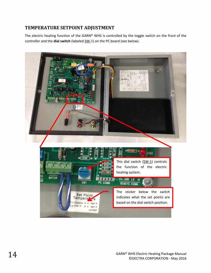
TEMPERATURE SETPOINT ADJUSTMENT
The electric heating function of the GARN® WHS is controlled by the toggle switch on the front of the
controller and the dial switch (labeled SW-1) on the PC board (see below).
This dial switch (SW-1) controls
the function of the electric
heating system.
The sticker below the switch
indicates what the set points are
based on the dial switch position.
Page 15
GARN® WHS Electric Heating Package Manual ©DECTRA CORPORATION - May 2016 (Supersedes September 2015 edition)
15
DIAL SWITCH POSITIONS
The dial switch controls the setpoint temperature of the Electric Heating Package. The dial switch may
be rotated clockwise or counter-clockwise to set switch to the desired position. Set the dial switch to
one of its four possible positions by hand, or by using a small blade screwdriver.
The table below lists the position number and the function corresponding to that position.
Dial Switch Position
Function Number
Visual Representation
(SW-1)
0
Not Used (Disabled): A setting of 0 means that the electric heating will not turn on. The controller will function the same as setting the toggle switch on the front of the controller to “WOOD” mode.
1
Outdoor Reset Mode: Targets a tank temperature based on the Outdoor Reset Curve (see Outdoor Reset Curve section of this manual). The electric elements will turn on if off-peak is available and the tank is below the target set point of the outdoor reset curve.
2
Freeze Protection Mode (50°F): Targets a tank temperature of 50°F. Temperature differential (deadband) = 5°F. If off-peak is available, the electrical elements will turn on if the tank is 45°F or below and remain on until the tank reaches 50°F.
The elements will not turn on unless off-peak is available. It is recommended that if the tank operates
in freeze protection mode, that the unit and piping directly connected to the unit be constantly circulated to prevent piping outside of the tank from freezing (if the unit is located in a generally unheated space). Because the tank has a large volume, there is no danger of freezing the tank even with a 16 hour or more carry-over between periods of electric availability.
3
Maximum Heat Mode (190°F): Targets a tank temperature of 190°F. Temperature differential (deadband) = 5°F. If off-peak is available, the electrical elements will turn on if the tank is 185°F or below and remain on until the tank reaches 190°F.
Page 16
GARN® WHS Electric Heating Package Manual ©DECTRA CORPORATION - May 2016
16
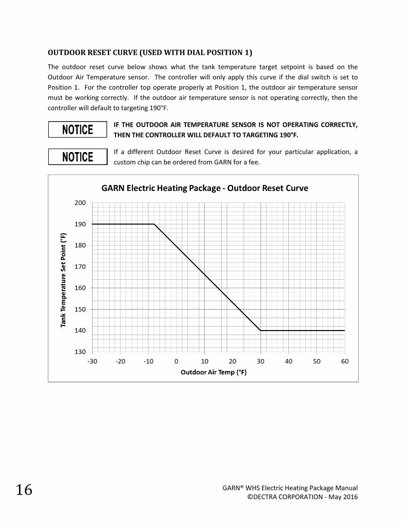
OUTDOOR RESET CURVE (USED WITH DIAL POSITION 1)
The outdoor reset curve below shows what the tank temperature target setpoint is based on the
Outdoor Air Temperature sensor. The controller will only apply this curve if the dial switch is set to
Position 1. For the controller top operate properly at Position 1, the outdoor air temperature sensor
must be working correctly. If the outdoor air temperature sensor is not operating correctly, then the
controller will default to targeting 190°F.
IF THE OUTDOOR AIR TEMPERATURE SENSOR IS NOT OPERATING CORRECTLY,
THEN THE CONTROLLER WILL DEFAULT TO TARGETING 190°F.
If a different Outdoor Reset Curve is desired for your particular application, a
custom chip can be ordered from GARN for a fee.
Page 17
GARN® WHS Electric Heating Package Manual ©DECTRA CORPORATION - May 2016 (Supersedes September 2015 edition)
17
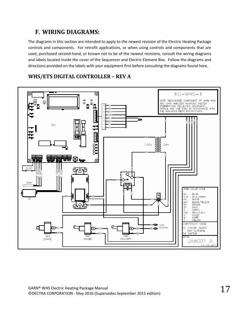
F. WIRING DIAGRAMS:
The diagrams in this section are intended to apply to the newest revision of the Electric Heating Package
controls and components. For retrofit applications, or when using controls and components that are
used, purchased second-hand, or known not to be of the newest revisions, consult the wiring diagrams
and labels located inside the cover of the Sequencer and Electric Element Box. Follow the diagrams and
directions provided on the labels with your equipment first before consulting the diagrams found here.
WHS/ETS DIGITAL CONTROLLER – REV A
Page 18
GARN® WHS Electric Heating Package Manual ©DECTRA CORPORATION - May 2016
18
WHS/ETS DIGITAL CONTROLLER – REV C
Page 19
GARN® WHS Electric Heating Package Manual ©DECTRA CORPORATION - May 2016 (Supersedes September 2015 edition)
19
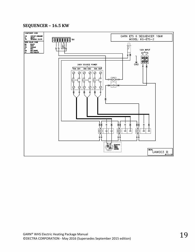
SEQUENCER – 16.5 KW
Page 20
GARN® WHS Electric Heating Package Manual ©DECTRA CORPORATION - May 2016
20
SEQUENCER – 33.0 KW
Page 21
GARN® WHS Electric Heating Package Manual ©DECTRA CORPORATION - May 2016 (Supersedes September 2015 edition)
21
SEQUENCER – 49.5 KW
The 49.5 kW heating package is made up of a 33 kW sequencer and 16.5 kW sequencer. Follow the
wiring diagrams for each individual sequencer from the previous sections. After the elements and high
voltage wiring is complete, the two sequencers must then be wired to work together as shown below.
The signal from the digital controller is wired to one sequencer which relays the signal to the second
sequencer. The sequencers are essentially wired in parallel so both sequencers are activated at the
same time when the controller calls for heat. A single high limit switch protects both sequencers.
Page 22
GARN® WHS Electric Heating Package Manual ©DECTRA CORPORATION - May 2016
22
IDENTIFYING YOUR BOARD REVISION
Your board revision will determine how the controller will interface with the sequencer. The
identification for your board is located in one of two spots. The board number begins with “UPC7115”
followed by the letters A or C. The letter indicates the revision of the board.
Revision UPC7115A has the label located here:
Revision UPC7115C has the label located here:
IDENTIFYING YOUR CHIP REVISION
The digital controller has the feature of being upgradeable. The latest version of the chip is supplied
with the purchase of the electric heating package. However, for reference, to identify the version of
chip that is installed in your board, read the label adhered to the chip:
Page 23
GARN® WHS Electric Heating Package Manual ©DECTRA CORPORATION - May 2016 (Supersedes September 2015 edition)
23
CONTROLLER TO SEQUENCER WIRING – BOARD REV: UPC7115-A
Wiring to the GARN WHS controller with a UPC7115A board requires a chip with version V1.21 or
greater. The latest version of the chip is supplied with the purchase of the electric heating package, but
if the equipment has been acquired second-hand (used), it is prudent to check the version to make sure
the heating package will function correctly. Check the chip version number by looking at the label
applied to the chip.
Two (2) conductors are wired from the OUT and COM connections on the board (terminals T10 and T11)
to the A and B terminals, respectively, on the sequencer. The C terminal on the sequencer is unused.
Page 24
GARN® WHS Electric Heating Package Manual ©DECTRA CORPORATION - May 2016
24
CONTROLLER TO SEQUENCER WIRING – BOARD REV: UPC7115-C
The Rev C board has three (3) wires between the controller and the sequencer. The third wire
(Connection C) is the “High Limit Monitor”. The High Limit Monitor sends a feedback signal to the
controller to tell the controller if the high limit is wired and working correctly. If the high limit is not
wired or operating properly, a sensor error will appear on the LCD display of the controller.
Page 25
GARN® WHS Electric Heating Package Manual ©DECTRA CORPORATION - May 2016 (Supersedes September 2015 edition)
25
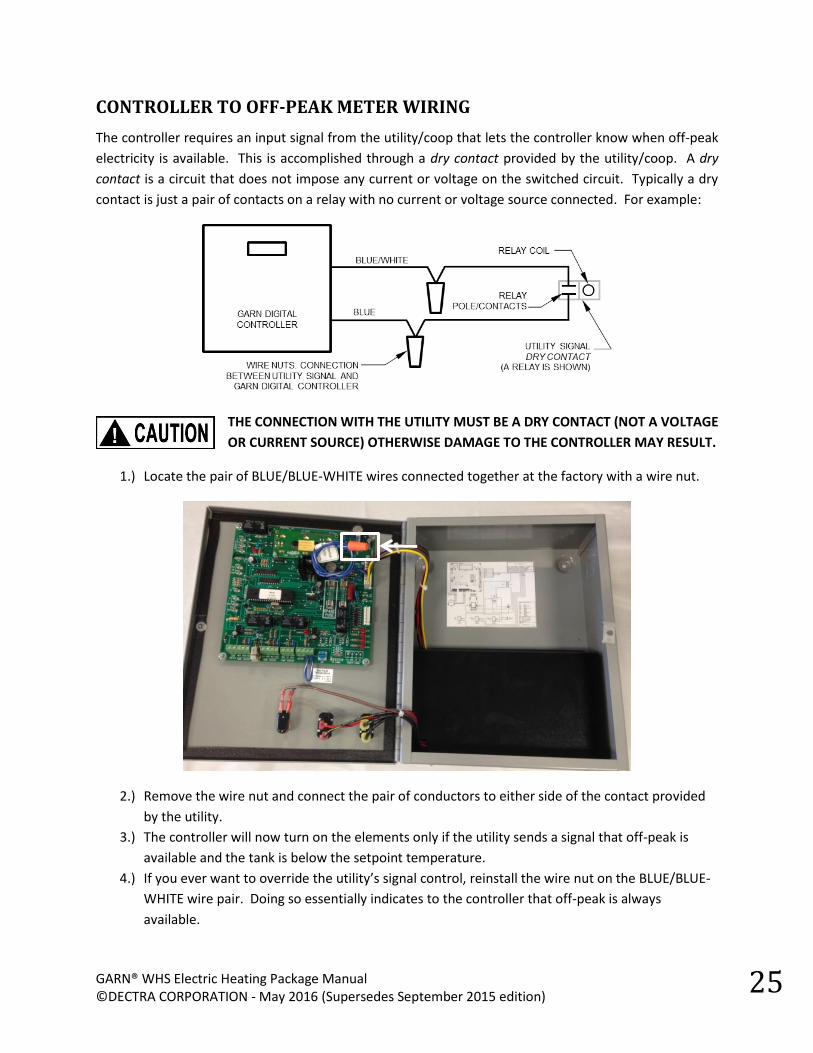
CONTROLLER TO OFF-PEAK METER WIRING
The controller requires an input signal from the utility/coop that lets the controller know when off-peak
electricity is available. This is accomplished through a dry contact provided by the utility/coop. A dry
contact is a circuit that does not impose any current or voltage on the switched circuit. Typically a dry
contact is just a pair of contacts on a relay with no current or voltage source connected. For example:
THE CONNECTION WITH THE UTILITY MUST BE A DRY CONTACT (NOT A VOLTAGE
OR CURRENT SOURCE) OTHERWISE DAMAGE TO THE CONTROLLER MAY RESULT.
1.) Locate the pair of BLUE/BLUE-WHITE wires connected together at the factory with a wire nut.
2.) Remove the wire nut and connect the pair of conductors to either side of the contact provided
by the utility.
3.) The controller will now turn on the elements only if the utility sends a signal that off-peak is
available and the tank is below the setpoint temperature.
4.) If you ever want to override the utility’s signal control, reinstall the wire nut on the BLUE/BLUE-
WHITE wire pair. Doing so essentially indicates to the controller that off-peak is always
available.
Page 26
GARN® WHS Electric Heating Package Manual ©DECTRA CORPORATION - May 2016
26
Schematically, the removal of the wire nut and connection to a dry contact is as follows:
1.) Remove the wire nut from the BLUE/BLUE-WHITE wire pair.
2.) Connect the BLUE/BLUE-WHITE wire pair to either side of a dry contact provided by the utility.
The contact is closed when off-peak is available and open when off-peak is not available.
Page 27
GARN® WHS Electric Heating Package Manual ©DECTRA CORPORATION - May 2016 (Supersedes September 2015 edition)
27
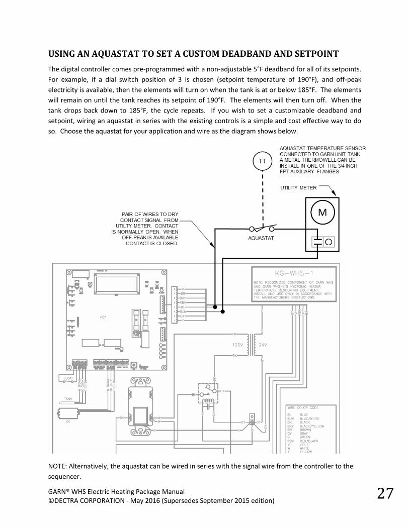
USING AN AQUASTAT TO SET A CUSTOM DEADBAND AND SETPOINT
The digital controller comes pre-programmed with a non-adjustable 5°F deadband for all of its setpoints.
For example, if a dial switch position of 3 is chosen (setpoint temperature of 190°F), and off-peak
electricity is available, then the elements will turn on when the tank is at or below 185°F. The elements
will remain on until the tank reaches its setpoint of 190°F. The elements will then turn off. When the
tank drops back down to 185°F, the cycle repeats. If you wish to set a customizable deadband and
setpoint, wiring an aquastat in series with the existing controls is a simple and cost effective way to do
so. Choose the aquastat for your application and wire as the diagram shows below.
NOTE: Alternatively, the aquastat can be wired in series with the signal wire from the controller to the
sequencer.
Page 28
GARN® WHS Electric Heating Package Manual ©DECTRA CORPORATION - May 2016
28
G. WARRANTY
GARN® products are warranted by the manufacturer to be free of defects in material and workmanship as follows, with the
below-enumerated exclusions:
With respect to the controls and miscellaneous parts furnished as part of the basic unit, a one-year warranty shall
apply.
With respect to the sequencer and electric element box, a five-year warranty shall apply with regard to materials and
workmanship.
With respect to wear items such as gaskets, electric elements, o-rings, etc., a one-year warranty shall apply regarding
materials and workmanship excluding normal wear and tear. Proper use and periodic maintenance will extend the life
of these items.
NO WARRANTY SHALL APPLY WITH REGARD TO EPOXY COATINGS, PAINT, CORROSION OR CORROSION INDUCED
FAILURES OF ANY COMPONENT OF THE UNIT OR COMPONENTS ATTACHED TO THE UNIT. It is the sole responsibility
of the owner to install, maintain and test water treatment chemicals in order to minimize corrosion potential and
damage. Testing of the GARN® water is required twice every year. A record of this compliance is required or warranty
is VOID.
DECTRA shall not be liable for injury, loss, damage or any expense directly or indirectly arising from the use of the
products it offers for sale or from any other cause.
This warranty does not cover any parts replacement due to shortage or damage in shipment, exposure to weather,
improper installation, operating the unit under abnormal conditions, or other claims not agreed to in writing by
DECTRA. Replacement parts purchased from DECTRA are warranted for ninety (90) days from the date of installation.
No warranty is given in connection with second-hand products and equipment, or products and equipment altered or
rebuilt without DECTRA’s knowledge or written approval.
No warranty is given regarding the predicted or actual performance of any product manufactured or supplied by
DECTRA.
THIS WARRANTY IS EXPRESSLY MADE IN LIEU OF ANY & ALL OTHER WARRANTIES, EXPRESSED OR IMPLIED. NO
WARRANTY OF MERCHANTABILITY OR OF FITNESS FOR PURPOSE SHALL APPLY. NO WARRANTY OF LOCAL CODE
ACCEPTANCE OR OF INSURANCE CARRIER ACCEPTANCE SHALL APPLY. NO WARRANTY FOR INSTALLATION OR FOR
HEATING SYSTEM PARTS OR PERFORMANCE SHALL APPLY.
The foregoing warranty periods shall each commence on the date of shipment to user of the products or parts and the obligation of DECTRA
with respect to such products or parts shall be limited to replacement or repair FOB point of origin, and in no event shall DECTRA be liable for
consequential or special damages, or for transportation, installation, adjustment, or other expenses which may arise in connection with such
products or parts. Determination of what is a defective part, assembly or product is the sole responsibility of DECTRA CORPORATION personnel.
The obligation of DECTRA hereunder with respect to any products or parts shall be to replace, or at its option, to repair parts determined to be
defective in materials or workmanship. Correction of any such defects by repair or replacement shall constitute fulfillment of all obligations of
DECTRA to the Purchaser hereunder.
DECTRA assumes no liability for labor or any other expenses incurred by anyone without DECTRA’s express written consent.
No person, agent or representative is authorized to give any additional warranty on behalf of DECTRA or assume for DECTRA
any other liability in connection with any GARN® products.
DECTRA CORPORATION • 3425 33rd Ave NE • St Anthony, Minnesota 55418
Phone: 612-781-3585 • www.garn.com