56
GEM ™ 2000 GEM ™ 2000 Plus GAS ANALYZER & EXTRACTION MONITOR OPERATION MANUAL For Serial Numbers less than 10,000
| Date post: | 23-Jan-2019 |
| Category: |
Documents |
| Upload: | vuonghuong |
| View: | 225 times |
| Download: | 0 times |

GEM™2000GEM™2000 PlusGAS ANALYZER & EXTRACTION MONITOR
OPERATION MANUALFor Serial Numbers less than 10,000
GEM™2000 & GEM™2000 Plus Operation Manual
Page ii
©Copyright 2010 by LANDTEC
All rights reserved. Printed in the United States of America. No part of this book may be used orreproduced in any form or by any means, or stored in a database or retrieval system, without consent of thepublisher. Making copies of any part of this book for any purpose other than your own personal use is aviolation of United States copyright laws.
LANDTEC, GEM and DataField are registered with the U.S. Patent and Trademark Office.
DataField software ©Copyright 1995-2005
For further information contact:
LANDTEC North America850 S. Via Lata, Suite 112Colton, CA 92324Telephone: (800) 821-0496 or (909) 783-3636Fax: (909) 825-0591www.LANDTECNA.com
This manual is subject to revision without prior notice. Please periodically check ourwebsite for a newer revision.
LANDTEC Release Date: December 2, 2010Updates to Clarify instruments are not total hydrocarbon analyzers, cross gas interference and solutions for typical interferences only.
Software, battery charger and data cable information is referenced to the equipment released at time of instrument sale (pre 2007).
GEM™2000 & GEM™2000 Plus Operation Manual
Page iii
Contents
1 INTRODUCTION........................................................................................................................1
2 GENERAL OPERATIONAL FEATURES...................................................................................22.1 PHYSICAL CHARACTERISTICS OF THE GEM™2000 / GEM™2000 PLUS .............................................. 22.2 TURNING THE INSTRUMENT ON/OFF .................................................................................................. 32.3 WARM-UP SELF TEST ....................................................................................................................... 32.4 WARNING AND ERROR DISPLAY......................................................................................................... 4
2.4.1 WARNING Displayed............................................................................................................... 42.4.2 ERROR Displayed ................................................................................................................... 4
2.5 STORAGE......................................................................................................................................... 42.6 BATTERY/CHARGING......................................................................................................................... 52.7 READ GAS LEVELS SCREEN (GA MODE OF OPERATION) ...................................................................... 62.8 OPTIONAL GAS PODS ....................................................................................................................... 62.9 COLD START .................................................................................................................................... 7
3 GENERAL OPERATIONS MENU.............................................................................................. 83.1 ZERO TRANSDUCERS........................................................................................................................ 83.2 UPDATE SITE DATA........................................................................................................................... 83.3 DATA LOGGING (GA MODE ONLY) ...................................................................................................... 83.4 PRINT DATA ..................................................................................................................................... 83.5 ADJUST CONTRAST........................................................................................................................... 83.6 FIELD CALIBRATION .......................................................................................................................... 8
3.6.1 Zero Channels ......................................................................................................................... 93.6.2 Span Channels ........................................................................................................................ 93.6.3 Factory Settings....................................................................................................................... 93.6.4 Last Field Cal........................................................................................................................... 9
3.7 MODE OF OPERATION ....................................................................................................................... 9
4 TAKING PROBE READINGS (GA MODE)..............................................................................104.1 PRELIMINARY CHECKS .................................................................................................................... 104.2 UPDATE SITE DATA......................................................................................................................... 104.3 TAKING READINGS – WITH ID.......................................................................................................... 104.4 TAKING READINGS – WITHOUT ID.................................................................................................... 114.5 TEMPERATURE PROBE READING ..................................................................................................... 124.6 CROSS-GAS EFFECTS .................................................................................................................... 12
4.6.1 Methane, Carbon Dioxide and Oxygen .................................................................................. 124.6.2 H2S, CO and other Optional Gas Pods .................................................................................. 13
4.7 MEMORY ........................................................................................................................................ 134.8 RF INTERFERENCE ......................................................................................................................... 13
5 TAKING EXTRACTION WELL READINGS (GEM MODE) .....................................................145.1 PRELIMINARY CHECKS .................................................................................................................... 145.2 UPDATE SITE DATA......................................................................................................................... 145.3 TAKING GAS AND FLOW READINGS (GEM MODE)............................................................................. 14
6 DATAFIELD CS SOFTWARE..................................................................................................166.1 INSTALLING DATAFIELD CS ............................................................................................................. 166.2 ESTABLISHING COMMUNICATIONS .................................................................................................... 176.3 MAIN SCREEN ................................................................................................................................ 196.4 CLOSE THE PROGRAM ..................................................................................................................... 196.5 COMMUNICATIONS .......................................................................................................................... 19

GEM™2000 & GEM™2000 Plus Operation Manual
Page iv
6.6 FUNCTIONS.................................................................................................................................... 206.6.1 Comments............................................................................................................................. 206.6.2 Entering IDs .......................................................................................................................... 226.6.3 Editing IDs............................................................................................................................. 256.6.4 Delete IDs ............................................................................................................................. 276.6.5 Re-sequencing ...................................................................................................................... 286.6.6 Readings............................................................................................................................... 306.6.7 Site Questions....................................................................................................................... 32
6.7 SETTINGS ...................................................................................................................................... 376.7.1 Instrument Settings ............................................................................................................... 376.7.2 Resource Links ..................................................................................................................... 43
7 FIELD OPERATIONS ..............................................................................................................447.1 LANDFILL GAS GENERATION ........................................................................................................... 447.2 SUBSURFACE FIRES ....................................................................................................................... 447.3 TECHNIQUES FOR CONTROLLING LANDFILL GAS............................................................................... 45
7.3.1 Controlling by Wellhead Valve Position ................................................................................. 457.3.2 Controlling by Wellhead Vacuum .......................................................................................... 457.3.3 Controlling by Gas Composition ............................................................................................ 457.3.4 Controlling by Flow Rate ....................................................................................................... 45
7.4 WELL FIELD MONITORING ............................................................................................................... 467.5 TYPICAL FIELD READINGS............................................................................................................... 467.6 ABBREVIATED FIELD READINGS....................................................................................................... 477.7 WELL FIELD ADJUSTMENT CRITERIA ................................................................................................ 477.8 ESTABLISHING TARGET FLOWS ....................................................................................................... 487.9 WELL FIELD OPTIMIZATION ............................................................................................................. 487.10 MIGRATION CONTROL—DEALING WITH POOR METHANE QUALITY ..................................................... 487.11 WELL FIELD ADJUSTMENT—PURPOSE AND OBJECTIVES................................................................... 49
8 TROUBLESHOOTING.............................................................................................................50
9 TECHNICAL SPECIFICATIONS..............................................................................................519.1 PHYSICAL ...................................................................................................................................... 519.2 GENERAL....................................................................................................................................... 519.3 POWER SUPPLY ............................................................................................................................. 519.4 GAS RANGES ................................................................................................................................. 519.5 PUMP ............................................................................................................................................ 529.6 OPERATING CONDITIONS ................................................................................................................ 529.7 OPTIONAL GAS PODS ..................................................................................................................... 52

GEM™2000 & GEM™2000 Plus Operation Manual
Page 1
1 IntroductionLANDTEC is the premier manufacturer of products, instruments and software for landfill gas extraction andfor regulatory monitoring compliance. LANDTEC has provided the landfill industry with a technologicallyinnovative family of products for more than a decade. These products are the result of field-provenexperience in design, operation and maintenance of landfills for environmental compliance.
The GEM™2000 and GEM™2000 Plus, designed by LANDTEC, are specifically for use on landfills tomonitor landfill gas (LFG) extraction systems, flares and migration control systems. Both instrumentssample and analyze the Methane, Carbon Dioxide and Oxygen content of LFG. The GEM™2000 Plus alsosamples and analyzes Carbon Monoxide and Hydrogen Sulfide. The GEM instruments are not totalhydrocarbon analyzers. The readings are displayed and can be stored in the instrument or downloaded to apersonal computer for reporting, analyzing and archiving.
The GEM™2000 / GEM™2000 Plus instrument is frequently shipped in an optional protective hard casewith a foam interior that offers additional protection, transportation convenience and component hardwarestorage. When properly sealed, the hard case is watertight. The hard case is equipped with a pressurerelief valve (located under the handle on the case) that is normally kept closed. If there is a change inelevation, the hard case may not open until turning the pressure relief valve equalizes internal pressure.When shipping a GEM™2000 / GEM™2000 Plus back to LANDTEC for calibration or service, always shipit in the original packaging to protect unit from damage.
Carefully unpack the contents of the GEM™2000 / GEM™2000 Plus, inspect and inventory them. Thefollowing items should be contained in your package:
The GEM™2000 / GEM™2000 Plus instrument GEM™2000 / GEM™2000 Plus Operation Manual Registration/Warranty Card Soft carrying case with replaceable protective window and carrying strap Clear ¼” vinyl sampling hose assembly (5 ft.) with external water trap filter assembly Blue ¼” vinyl pressure sampling hose (5 ft.) Spare internal particulate filter element Polypropylene male connector (hose barb) connects to blue vinyl tubing Spare external water trap filter element 100-240 volt battery charger DataField CS software on CD-ROM RS-232 serial cable for computer/printer data downloading Temperature probe (optional) Hard carrying case (optional)
Complete the Registration/Warranty Card and return it to LANDTEC. The model and serial numbers arelocated on the back of the GEM™2000 / GEM™2000 Plus instrument.
Immediately notify shipping company if the GEM™2000 / GEM™2000 Plus unit or accessories aredamaged due to shipping. Contact LANDTEC immediately if any items are missing.
For questions regarding instrument operation and procedures, please contact LANDTEC

GEM™2000 & GEM™2000 Plus Operation Manual
Page 2
2 General Operational Features
2.1 Physical Characteristics of the GEM™2000 / GEM™2000 Plus
Front View Back View
SampleInlet
or StaticPressure
Port
ExhaustPort
RS232CommunicationSocket
ChargerSocket
ParticulateFilter
Housing
ImpactPressure
Port
Left Side View
Charger SocketRS232 CommunicationSocket for Computer Cable,optional Temperature Probeor optional Gas Pod
Exhaust Port

GEM™2000 & GEM™2000 Plus Operation Manual
Page 3
Right Side View
Sample Inlet orStatic Pressure Port
Impact Pressure Port
On/Off Key
Enter/StoreKey
Pump operation andBack Space Key
Backlight operation and‘0’ (zero) Key
Number entryKeys
Number entry,Navigationand Cursor
Keys
Keypad
Whenever a key is pressed the unit will emit a short ‘beep’ as an acknowledgement. This function cannotbe turned off.
2.2 Turning the Instrument On/OffWhen switching the instrument on, a long beep will sound, followed by the LANDTEC logo being displayedand the self-test will commence.
When switching the instrument off, the On/Off button must be held down for approximately 15 seconds, atwhich point a clean air purge will be carried out. If for any reason the instrument ‘locks-up’ and will notswitch off, press and hold the On/Off button for 15 seconds. This will force the instrument to switch off.
2.3 Warm-up Self TestWhen switched on, the instrument will perform a predetermined self-test sequence taking approximately 20seconds, during this time many of the instrument’s functions are tested, including: General operation Pump function Gas flow measurement Calibration Backlight function Solenoid function
GEM™2000 & GEM™2000 Plus Operation Manual
Page 4
During the self-test, the following information is also displayed: Calibration due date. Software version. Lifetime guarantee covered (or not). Date format. Serial Number. Operating language.
Upon self-test completion, the GEM™2000 / GEM™2000 Plus should automatically enter the read gaslevels screen.
2.4 Warning and Error DisplayDuring the self-test, if any operational parameters are out of specification or the pre-programmedrecommended calibration/service date has passed errors or warnings may be displayed. Only threeerrors/warnings can be displayed at any time. To ascertain if more errors occurred, use the ‘’ and ‘’ keyto scroll up/down the list.
2.4.1 WARNING DisplayedAll warnings displayed will be prefixed by the word ‘WARNING‘ followed by a relevant description. Twotypes of warnings may be displayed.
1. General warnings that may not have an effect on the instrument’s function and those where the self-test has detected a function that is outside the usual programmed operating criteria (e.g. Batterycharge low, memory nearly full, etc.).
2. Specific warnings of operational parameters that can affect the performance of the instrument (e.g.O2 Cell out of calibration, CH4 out of calibration, CO2 out of calibration, etc.).
The most likely reason for the errors is either an incorrect user calibration, or sensor failure. If an incorrectuser calibration has caused the warning, it should be correctable by way of returning the instrument tofactory settings, zeroing or carrying out a user calibration as necessary for the relevant function.
2.4.2 ERROR DisplayedAll errors displayed will be prefixed by the word ‘ERROR‘ followed by a number and description. The errorsdetected by the self-test are usually caused by a user calibration being out of specification or possiblymemory corruption. This will have an effect on the functionality of the instrument and should be correctedbefore use (e.g. 01 - User cal data, CH4 reading or channel out of specification, 02 - User cal data, CO2reading out of specification).
If any other Warnings or Errors are displayed, contact LANDTEC for further information.LANDTEC is the ONLY authorized service center for the GEM™2000 / GEM™2000 Plus instrumentsin the Americas.
2.5 StorageDo not keep the instrument in the trunk of a car or shed because it may be exposed to temperatureextremes.
When not in use, instruments should be kept in a clean, dry and warm environment such as an office.
GEM™2000 & GEM™2000 Plus Operation Manual
Page 5
The instrument batteries should be discharged and fully charged at least once every four weeks regardlessof indicated charge state. The discharge function may be carried out with the use of the Data LoggingFunction in GA mode of operation.
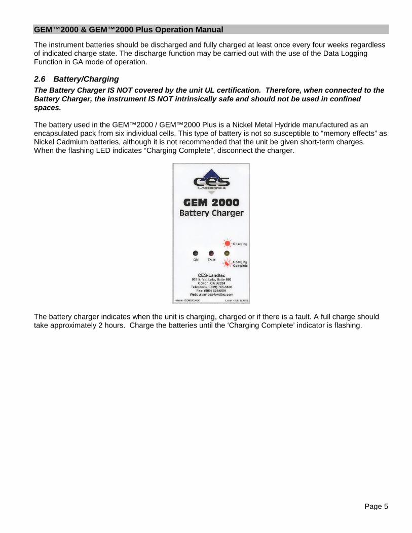
2.6 Battery/ChargingThe Battery Charger IS NOT covered by the unit UL certification. Therefore, when connected to theBattery Charger, the instrument IS NOT intrinsically safe and should not be used in confinedspaces.
The battery used in the GEM™2000 / GEM™2000 Plus is a Nickel Metal Hydride manufactured as anencapsulated pack from six individual cells. This type of battery is not so susceptible to “memory effects” asNickel Cadmium batteries, although it is not recommended that the unit be given short-term charges.When the flashing LED indicates “Charging Complete”, disconnect the charger.
The battery charger indicates when the unit is charging, charged or if there is a fault. A full charge shouldtake approximately 2 hours. Charge the batteries until the ‘Charging Complete’ indicator is flashing.
GEM™2000 & GEM™2000 Plus Operation Manual
Page 6
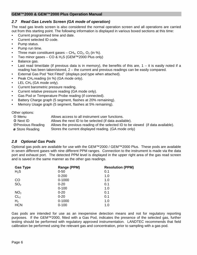
2.7 Read Gas Levels Screen (GA mode of operation)The read gas levels screen is also considered the normal operation screen and all operations are carriedout from this starting point. The following information is displayed in various boxed sections at this time: Current programmed time and date. Current selected ID code. Pump status. Pump run time. Three main constituent gases – CH4, CO2, O2 (in %). Two minor gases – CO & H2S (GEM™2000 Plus only) Balance gas. Last read time/date (if previous data is in memory), the benefits of this are, 1 – it is easily noted if a
reading has been taken/stored, 2 – the current and previous readings can be easily compared. External Gas Pod “Not Fitted” (displays pod type when attached). Peak CH4 reading (in %) (GA mode only). LEL CH4 (GA mode only). Current barometric pressure reading. Current relative pressure reading (GA mode only). Gas Pod or Temperature Probe reading (if connected). Battery Charge graph (5 segment, flashes at 20% remaining). Memory Usage graph (5 segment, flashes at 5% remaining).
Other options: Menu Allows access to all instrument user functions. Next ID Allows the next ID to be selected (if data available).Previous Reading Allows the previous reading of the selected ID to be viewed (if data available). Store Reading Stores the current displayed reading. (GA mode only)
2.8 Optional Gas PodsOptional gas pods are available for use with the GEM™2000 / GEM™2000 Plus. These pods are availablein seven different gases with nine different PPM ranges. Connection to the instrument is made via the dataport and exhaust port. The detected PPM level is displayed in the upper right area of the gas read screenand is saved in the same manner as the other gas readings.
Gas Type Range (PPM) Resolution (PPM)H2S 0-50 0.1
0-200 1.0CO 0-1000 1.0SO2 0-20 0.1
0-100 1.0NO2 0-20 0.1CL2 0-20 0.1H2 0-1000 1.0HCN 0-100 1.0
Gas pods are intended for use as an inexpensive detection means and not for regulatory reportingpurposes. If the GEM™2000, fitted with a Gas Pod, indicates the presence of the selected gas, furthertesting should be performed with regulatory approved instrumentation. LANDTEC recommends that fieldcalibration be performed using the relevant gas and concentration, prior to sampling with a gas pod.

GEM™2000 & GEM™2000 Plus Operation Manual
Page 7
2.9 Cold StartTHIS FUNCTION SHOULD BE USED ONLY AS A LAST RESORT.(For Gas Calibration Error Messages, confirm that Factory Setting and User Calibration is done).
A Cold Start should only be carried out to correct an instrument if no other course of action has provedsuccessful. This function WILL ERASE the instrument memory entirely. After a cold start is performed theuser will need to reset the instrument to factory settings, perform a field calibration and reset the internaltime/date to the default settings. Please note that the time/date may only be updated through DataFieldsoftware. It cannot be updated manually.
To carry out a cold start, turn the instrument on, during the self-test press and continue to hold the ‘’ keyuntil the self-test has been completed. Upon completion of the self-test, a pass code entry screen will bedisplayed. At this point the ‘’ key may be released. Enter the code 12345 and press ‘’ to confirm.
After the pass-code entry has been accepted, the instrument serial number will be displayed along with thehours of operation and two options:
1 - Cold Start0 - Continue
ONLY select option ‘1’ if a Cold Start is to be carried out. Press key ‘1’ to confirm this operation. The coldstart menu will be displayed again, press key ‘0’ to continue with normal operation.

GEM™2000 & GEM™2000 Plus Operation Manual
Page 8
3 General Operations Menu
The following features and functions are selectable from the main menu via key ‘ Menu’ from the readgas levels screen. Various options are available to the user including:
3.1 Zero TransducersThis function allows the user to zero the pressure transducer(s). Upon selection, the current pressurereading is displayed. The operation will be carried out when the ‘’ is pressed.
3.2 Update Site DataAllows the user to answer questions (pre-defined in DataField software) relating to the site (e.g. name ofoperator, weather conditions, etc.). Site Questions are different from Site Comments.
This is covered in detail in Section 6 of this manual.
3.3 Data Logging (GA mode only)Enables the user to leave the Instrument unattended to take samples at a pre-determined time. Thereading interval and pump run time may be edited prior to commencing the logging cycle. The ID code mayONLY be set in DataField communication software.
Once the logging function is activated, the instrument will carry out a 30 second ‘Warm-up’ countdown(displayed bottom right) and begin the first sample. After each sample, the unit will shut down (sleep) toconserve power if the time between the pump ending and the next sample is greater than 30 seconds.
The instrument is reactivated (awakened) during a logging cycle, the company logo will be displayed for afew seconds and the read gas levels screen will be displayed. This will initiate a 30 second countdown tothe next sample being taken unless the operator stops the logging function.
If for any reason during a logging cycle the inlet port were to become blocked the Instrument will sense thisas a flow fail during the ‘pump on’ time and will automatically retry until a reading can be obtained.Therefore, position the sample tubing carefully to ensure no blockage due to water/moisture can occur.
3.4 Print DataAllows ALL the data currently stored to be printed. This may ONLY be carried out with an appropriateRS232 cable (included with new instruments & available from LANDTEC) and a printer with a serial portconnection.
3.5 Adjust ContrastThe GEM™2000 automatically adjusts the screen contrast according to the ambient temperature tomaintain normal viewing.
The contrast can be manually adjusted by using the ‘’ and ‘’ cursor keys. The manual contrast setting isstored when the instrument is switched off.
3.6 Field CalibrationWhenever carrying out a user calibration function it is important to ensure the correct value is entered.Additionally, in the case of a zeroing function, ensure only ambient air is used and no connection is made toa probe or wellhead fitting. The calibration cylinders sold by LANDTEC have a volume of 17 liters. Theregulator, sold by same, is set to 0.5 liters per minute and 15 psig maximum. A normal field calibrationusually requires the gas to be running for about two minutes.
GEM™2000 & GEM™2000 Plus Operation Manual
Page 9
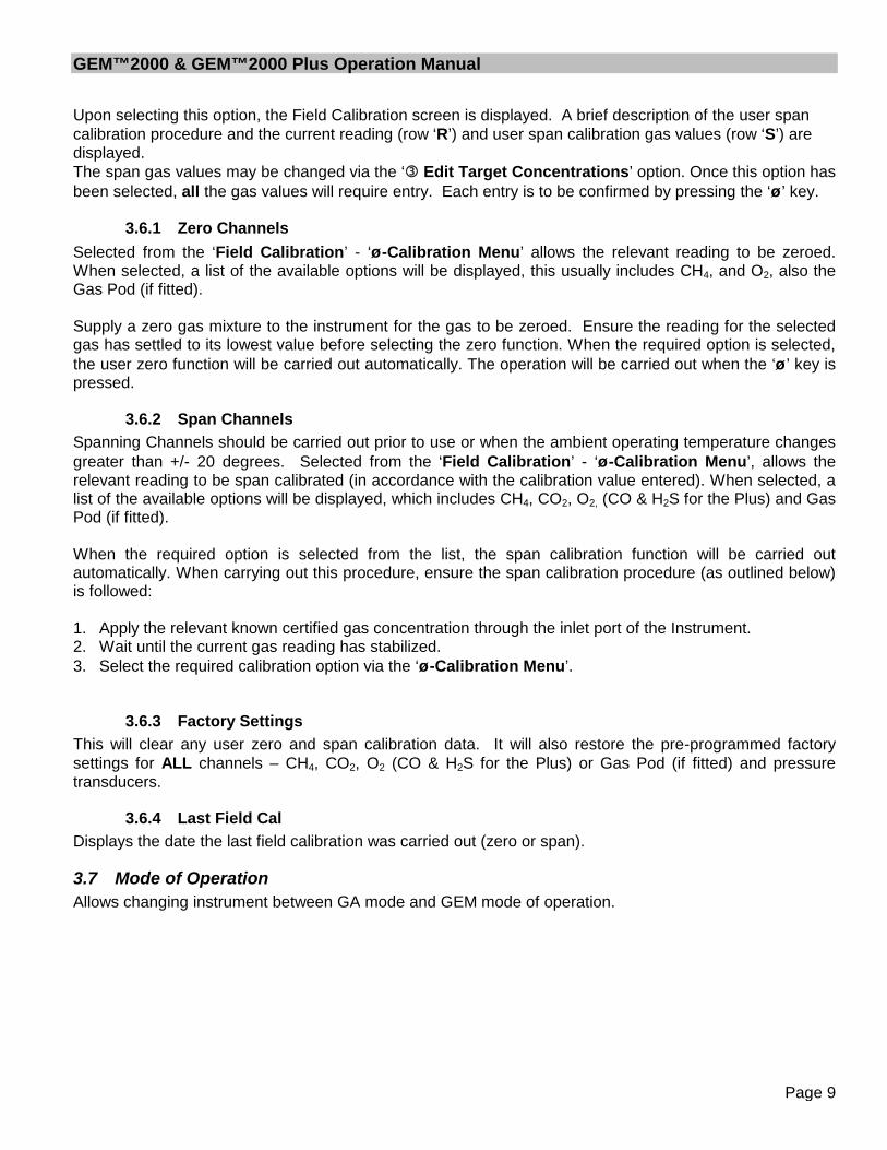
Upon selecting this option, the Field Calibration screen is displayed. A brief description of the user spancalibration procedure and the current reading (row ‘R’) and user span calibration gas values (row ‘S’) aredisplayed.The span gas values may be changed via the ‘ Edit Target Concentrations’ option. Once this option hasbeen selected, all the gas values will require entry. Each entry is to be confirmed by pressing the ‘’ key.
3.6.1 Zero ChannelsSelected from the ‘Field Calibration’ - ‘-Calibration Menu’ allows the relevant reading to be zeroed.When selected, a list of the available options will be displayed, this usually includes CH4, and O2, also theGas Pod (if fitted).
Supply a zero gas mixture to the instrument for the gas to be zeroed. Ensure the reading for the selectedgas has settled to its lowest value before selecting the zero function. When the required option is selected,the user zero function will be carried out automatically. The operation will be carried out when the ‘’ key ispressed.
3.6.2 Span ChannelsSpanning Channels should be carried out prior to use or when the ambient operating temperature changesgreater than +/- 20 degrees. Selected from the ‘Field Calibration’ - ‘-Calibration Menu’, allows therelevant reading to be span calibrated (in accordance with the calibration value entered). When selected, alist of the available options will be displayed, which includes CH4, CO2, O2, (CO & H2S for the Plus) and GasPod (if fitted).
When the required option is selected from the list, the span calibration function will be carried outautomatically. When carrying out this procedure, ensure the span calibration procedure (as outlined below)is followed:
1. Apply the relevant known certified gas concentration through the inlet port of the Instrument.2. Wait until the current gas reading has stabilized.3. Select the required calibration option via the ‘-Calibration Menu’.
3.6.3 Factory SettingsThis will clear any user zero and span calibration data. It will also restore the pre-programmed factorysettings for ALL channels – CH4, CO2, O2 (CO & H2S for the Plus) or Gas Pod (if fitted) and pressuretransducers.
3.6.4 Last Field CalDisplays the date the last field calibration was carried out (zero or span).
3.7 Mode of OperationAllows changing instrument between GA mode and GEM mode of operation.
GEM™2000 & GEM™2000 Plus Operation Manual
Page 10
4 Taking Probe Readings (GA Mode)
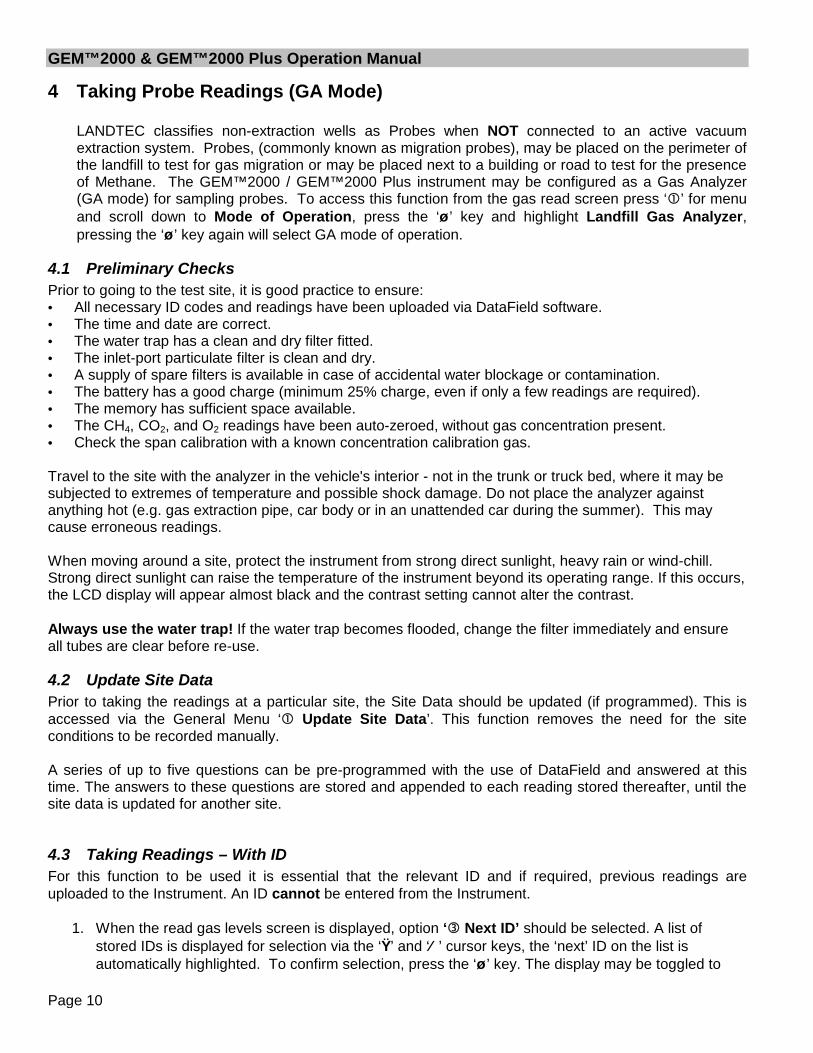
LANDTEC classifies non-extraction wells as Probes when NOT connected to an active vacuumextraction system. Probes, (commonly known as migration probes), may be placed on the perimeter ofthe landfill to test for gas migration or may be placed next to a building or road to test for the presenceof Methane. The GEM™2000 / GEM™2000 Plus instrument may be configured as a Gas Analyzer(GA mode) for sampling probes. To access this function from the gas read screen press ‘’ for menuand scroll down to Mode of Operation, press the ‘’ key and highlight Landfill Gas Analyzer,pressing the ‘’ key again will select GA mode of operation.
4.1 Preliminary ChecksPrior to going to the test site, it is good practice to ensure: All necessary ID codes and readings have been uploaded via DataField software. The time and date are correct. The water trap has a clean and dry filter fitted. The inlet-port particulate filter is clean and dry. A supply of spare filters is available in case of accidental water blockage or contamination. The battery has a good charge (minimum 25% charge, even if only a few readings are required). The memory has sufficient space available. The CH4, CO2, and O2 readings have been auto-zeroed, without gas concentration present. Check the span calibration with a known concentration calibration gas.
Travel to the site with the analyzer in the vehicle's interior - not in the trunk or truck bed, where it may besubjected to extremes of temperature and possible shock damage. Do not place the analyzer againstanything hot (e.g. gas extraction pipe, car body or in an unattended car during the summer). This maycause erroneous readings.
When moving around a site, protect the instrument from strong direct sunlight, heavy rain or wind-chill.Strong direct sunlight can raise the temperature of the instrument beyond its operating range. If this occurs,the LCD display will appear almost black and the contrast setting cannot alter the contrast.
Always use the water trap! If the water trap becomes flooded, change the filter immediately and ensureall tubes are clear before re-use.
4.2 Update Site DataPrior to taking the readings at a particular site, the Site Data should be updated (if programmed). This isaccessed via the General Menu ‘ Update Site Data’. This function removes the need for the siteconditions to be recorded manually.
A series of up to five questions can be pre-programmed with the use of DataField and answered at thistime. The answers to these questions are stored and appended to each reading stored thereafter, until thesite data is updated for another site.
4.3 Taking Readings – With IDFor this function to be used it is essential that the relevant ID and if required, previous readings areuploaded to the Instrument. An ID cannot be entered from the Instrument.
1. When the read gas levels screen is displayed, option ‘ Next ID’ should be selected. A list ofstored IDs is displayed for selection via the ‘’ and ‘’ cursor keys, the ‘next’ ID on the list isautomatically highlighted. To confirm selection, press the ‘’ key. The display may be toggled to
GEM™2000 & GEM™2000 Plus Operation Manual
Page 11
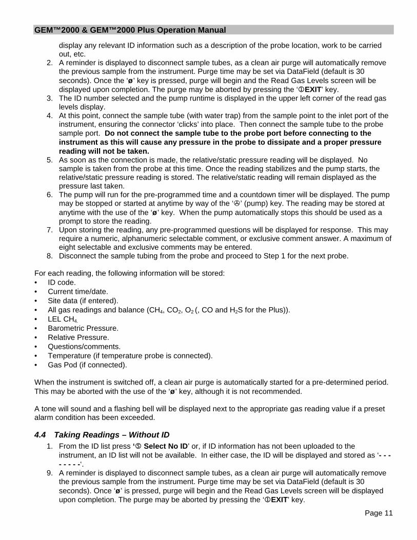
display any relevant ID information such as a description of the probe location, work to be carriedout, etc.
2. A reminder is displayed to disconnect sample tubes, as a clean air purge will automatically removethe previous sample from the instrument. Purge time may be set via DataField (default is 30seconds). Once the ‘’ key is pressed, purge will begin and the Read Gas Levels screen will bedisplayed upon completion. The purge may be aborted by pressing the ‘EXIT’ key.
3. The ID number selected and the pump runtime is displayed in the upper left corner of the read gaslevels display.
4. At this point, connect the sample tube (with water trap) from the sample point to the inlet port of theinstrument, ensuring the connector ‘clicks’ into place. Then connect the sample tube to the probesample port. Do not connect the sample tube to the probe port before connecting to theinstrument as this will cause any pressure in the probe to dissipate and a proper pressurereading will not be taken.
5. As soon as the connection is made, the relative/static pressure reading will be displayed. Nosample is taken from the probe at this time. Once the reading stabilizes and the pump starts, therelative/static pressure reading is stored. The relative/static reading will remain displayed as thepressure last taken.
6. The pump will run for the pre-programmed time and a countdown timer will be displayed. The pumpmay be stopped or started at anytime by way of the ‘’ (pump) key. The reading may be stored atanytime with the use of the ‘’ key. When the pump automatically stops this should be used as aprompt to store the reading.
7. Upon storing the reading, any pre-programmed questions will be displayed for response. This mayrequire a numeric, alphanumeric selectable comment, or exclusive comment answer. A maximum ofeight selectable and exclusive comments may be entered.
8. Disconnect the sample tubing from the probe and proceed to Step 1 for the next probe.
For each reading, the following information will be stored: ID code. Current time/date. Site data (if entered). All gas readings and balance (CH4, CO2, O2 (, CO and H2S for the Plus)). LEL CH4.
Barometric Pressure. Relative Pressure. Questions/comments. Temperature (if temperature probe is connected). Gas Pod (if connected).
When the instrument is switched off, a clean air purge is automatically started for a pre-determined period.This may be aborted with the use of the ‘’ key, although it is not recommended.
A tone will sound and a flashing bell will be displayed next to the appropriate gas reading value if a presetalarm condition has been exceeded.
4.4 Taking Readings – Without ID1. From the ID list press ‘ Select No ID’ or, if ID information has not been uploaded to the
instrument, an ID list will not be available. In either case, the ID will be displayed and stored as ‘- - -- - - - -‘.
9. A reminder is displayed to disconnect sample tubes, as a clean air purge will automatically removethe previous sample from the instrument. Purge time may be set via DataField (default is 30seconds). Once ‘’ is pressed, purge will begin and the Read Gas Levels screen will be displayedupon completion. The purge may be aborted by pressing the ‘EXIT’ key.

GEM™2000 & GEM™2000 Plus Operation Manual
Page 12
2. At this point, connect the sample tube (with water trap) from the sample point to the inlet port of theinstrument, ensuring the connector ‘clicks’ in to place.
3. Now connect the sample tube to the probe sample port. Do not connect the sample tube to theprobe port before connecting to the instrument as this will cause any pressure in the probeto dissipate and a proper pressure reading will not be taken.
4. The pump may be started or stopped at anytime by way of the ‘’ (pump) key and a ‘time-on’ timerwill be displayed. The pump should always be stopped using the ‘’ key, before storing a reading.
5. Upon storing the reading, a virtual keyboard will be displayed for any alphanumeric comments to beentered.
6. Disconnect the sample tubing from the probe and proceed from step 1 for the next probe.
Except for the ID code information, which will be stored as ‘- - - - - - - -‘, and probe questions, for eachreading the information stored will be the same as that for a reading with an ID.
A tone will sound and a flashing bell will be displayed next to the appropriate gas reading value if a presetalarm condition has been exceeded.
4.5 Temperature Probe ReadingThe GEM™2000 / GEM™2000 Plus has the facility to automatically display and record the probetemperature via an optional temperature probe (TP-100). When a temperature probe is fitted to the RS232Communication Socket, the temperature will be displayed in the read gas levels screen and recorded withall other data. The temperature probe is part of the GEM™2000 UL certification and is therefore certified foruse under the same conditions as the instrument.
4.6 Cross-Gas Effects
4.6.1 Methane, Carbon Dioxide and OxygenMethane is measured using dual beam infrared absorption. The Methane reading is filtered to anabsorption frequency of 3.41m (nominal). Instruments are calibrated using certified Methane mixtures andwill give correct readings provided there are no other hydrocarbon gasses present within the sample (e.g.ethane, propane, butane, etc.). If there are other hydrocarbons present, the Methane reading will be higher(never lower) than the actual Methane concentration being monitored.
The extent to which the Methane reading is affected depends upon the concentration of the Methane in thesample and the concentration of the other hydrocarbons. The effect is non-linear and difficult to predict.The instrument does not read total hydrocarbons. If other hydrocarbons are present in the sample gas afilter should be used to remove them and mitigate the cross gas effects. Typically trace levels of otherhydrocarbons (<100ppm) will not induce a cross gas effect and do not require filtering.
The Carbon Dioxide reading is filtered to an infrared absorption frequency of 4.29µm (nominal), thefrequency specific to Carbon Dioxide. Therefore, any other gases usually found on landfill sites will notaffect the Carbon Dioxide reading.
The Oxygen sensor is a galvanic cell type and suffers virtually no influence from CO2, CO, H2S, SO2 or H2,unlike many other types of Oxygen cell.
The infrared sensors will not be "poisoned" by cross gas effects. Normal operation will resume as soon asthe gas sample has been purged.
Note - there has been one reported incident of a high reading due to the presence of Carbon Disulfide,which has a similar absorption frequency to Carbon Dioxide.

GEM™2000 & GEM™2000 Plus Operation Manual
Page 13
4.6.2 H2S, CO and other Optional Gas PodsThe Gas Pods used to measure H2S and CO do suffer from cross-gas effects. Such effects are notaccurately specified. However, the following table may be useful as a guide. This table represents howmany ppm would be read by a Gas Pod if 100ppm of the interfering gas was applied, (with no other cross-contaminates being present in the sample).
Cell CO H2S SO2 NO2 CL2 H2 CH4 CO2CO 100 <3 0 <-20 0 <40 0 0H2S <0.5 100 ~20 ~-20 ~0.1 0 0
NOTE: All readings are given in parts per million (ppm). The life of an electrochemical cell is determined byexposure to gasses, typical life being one to two years. It is recommended that Gas Pods be field calibratedat regular intervals.
NOTE: Cross-gas effects can be mitigated by employing a filter for the gas not being tested. TheGEM™2000 Plus has a built-in H2S filter to protect the CO sensor.
4.7 MemoryThe instrument's memory is volatile. It is maintained by a battery back-up system, which will maintain thememory while the battery is being changed.
The memory is not to be used as a permanent storage medium and any data should be transferred to amore permanent storage medium as soon as possible. An Instrument should never be stored for prolongedperiods with valuable data in its memory.
Although unlikely, sudden shocks, high levels of electromagnetic interference or static discharge maycause memory corruption or loss. If this occurs, the instrument should be Cold Started and the calibrationreset to factory settings before further use. Cold starting will erase all data in the instrument includingresetting the time and date to the default value.
4.8 RF InterferenceThe gas sensors, especially the Methane sensor, are sensitive to RF interference.
Any device that transmits radio waves can cause your gas readings to fluctuate. Cell phones are the mostcommon cause of the problem. You should never use your cell phone while you are taking gas readings.

GEM™2000 & GEM™2000 Plus Operation Manual
Page 14
5 Taking Extraction Well Readings (GEM Mode)LANDTEC classifies gas-producing penetrations on landfills as wells when used with vacuumextraction systems and flow determining devices such as the Accu-Flo wellheads, orifice plates or pitottubes. The GEM™2000 / GEM™2000 Plus may be configured as a Gas Extraction Monitor (GEMmode) for the purpose of sampling wells and obtaining flow measurements. To access this functionfrom the gas read screen press ‘’ and scroll down to Mode of Operation, press the ‘’ key andhighlight Gas Extraction Monitor, pressing the ‘’ key again will select GEM mode of operation.
5.1 Preliminary ChecksPrior to going on site, it is good practice to ensure: All necessary ID codes and readings have been uploaded via DataField software. The time and date are correct. The water trap has a clean and dry filter fitted. The inlet-port particulate filter is clean and dry. A supply of spare filters is available in case of accidental water blockage or contamination. The battery has a good charge (minimum 25% charge, even if only a few readings are required). The memory has sufficient space available. The CH4, CO2 and O2 readings have been auto-zeroed without gas concentration present. Check the span calibration with a known concentration calibration gas.
Travel to the site with the analyzer in the vehicle's interior - not in the trunk or truck bed, where it may besubjected to extremes of temperature and possible shock damage. Do not place the analyzer againstanything hot (e.g. gas extraction pipe, car body or in an unattended car during the summer). This maycause erroneous readings.
When moving around a site, protect the instrument from strong direct sunlight, heavy rain or wind-chill.Strong direct sunlight can raise the temperature of the instrument beyond its operating range. If this occurs,the LCD display will appear almost black and the contrast setting cannot alter the contrast.
Always use the water trap! If the water trap becomes flooded, change the filter immediately and ensureall tubes are clear before re-use.
5.2 Update Site DataPrior to taking the readings at a particular site, the Site Data should be updated (if programmed). This isaccessed via the General Menu ‘’. This function removes the need for the site conditions to be recordedmanually. A series of up to five questions can be pre-programmed with the use of DataField and answeredat this time. The answers to these questions are stored and appended to each reading stored thereafter,until the site data is updated for another site.
5.3 Taking Gas and Flow Readings (GEM Mode)The GEM mode of operation is designed to allow for gas flow (SCFM) and energy measurements (BTU) tobe calculated at the wellhead. This function requires the use of an ID that has been uploaded fromDataField software with the type of flow device defined. Gas flow and BTU will not be calculated if thisaction has not been performed.
1. When the gas read screen is displayed select ‘ Next ID’. A list of stored IDs will be displayed forselection via the ‘’ and ‘’ cursor keys, the ‘next’ ID is automatically highlighted, to confirm theselection press the ‘’ key. The screen may be toggled to display any relevant ID information such as adescription of the well location, work to be carried out, etc.

GEM™2000 & GEM™2000 Plus Operation Manual
Page 15
2. A reminder is displayed to disconnect sample tubes, as a clean air purge will automatically remove theprevious sample from the instrument. Purge time may be set via DataField (default is 30 seconds).Once the ‘’ key is pressed, purge will begin and the Read Gas Levels screen will be displayed uponcompletion. The purge may be aborted by pressing the ‘EXIT’ key.
3. Connect the sample tubes (with water trap filter) to the wellhead ensuring the gas sample tube andimpact pressure tubes are properly oriented. Insert the temperature probe if used.
4. Press the ‘’ key to start the sample pump; a countdown timer will be displayed in the upper left area ofthe display. The pump may be stopped and restarted and any time by pressing the ‘’ key. The pumprun time is set in DataField software. Allow the gas readings to stabilize and press ‘Measure Flow’key, this will store the gas level readings and display the ‘PRESSURE READINGS’ screen. Note; aflashing bell will be displayed next to the appropriate gas and a beeping tone will be heard, if a presetalarm condition has been exceeded.
5. The ‘PRESSURE READINGS’ screen will prompt the user to disconnect the sample tubes and allow thepressure to stabilize. Once the pressure has stabilized press ‘ Zero Transducers’. Press ‘’ tocontinue. Note; if Accu-Flo wellheads are used this zero function may be performed prior to connectingthe sample tubes to the well head by selecting ‘ MENU’ and highlighting ‘ZERO TRANSDUCERS’.This eliminates the need to disconnect and re-connect the sample tubes on the same wellhead.
6. If a temperature probe is not connected, the user is prompted to manually input the gas temperature,press the ‘’ key when entry is finished.
7. The gas flow and energy screen is now displayed showing all the gas level readings taken in the gasread screen as well as the level of gas flow (SCFM) and power (BTU). In addition, Adjusted, Currentand Previous (if downloaded) readings are displayed so modifications may be made to the well ifrequired.
8. Pressing ‘ STORE’ will save the readings to memory. Then, the comments screen (if comments wereloaded) will display and allow you to answer questions or select comments about the condition of thewell. A total of seven comments and one exclusive comment may be stored with each ID.
9. Press ‘ NEXT ID’ and proceed to the next wellhead. An automatic purge will be performed at thistime to ensure the sample has been exhausted from the instrument.
For each reading, the following information will be stored: ID code. Current time/date. Site data (if entered). All gas readings and balance gas (CH4, CO2, O2 (CO & H2S for the Plus)). Barometric Pressure. Temperature. Gas Pod (if connected). Gas flow (SCFM) and Power (BTU). Comments and exclusive comment.
When the Instrument is switched off, a clean air purge is automatically started for a pre-determined globalperiod. This may be aborted by pressing the ‘’ key, although we do not recommend this action.

GEM™2000 & GEM™2000 Plus Operation Manual
Page 16
6 DataField CS SoftwareDataField CS is an integrated software program designed to communicate with the GEM™2000, Plus,GEM™2000, GEM™500 and GA-90 instruments. The software will create files used for storing gas readdata, ID data, comments and instrument configuration data. The files created are significantly differentfrom the files created with GEM_COMM or GA_COMM software and are not compatible with these versionsof software.
DataField CS is browser based (Java enabled) and will operate on Windows 98/ME/NT/2000/XP operatingsystems. Recommended hardware requirements are:
Pentium III 500 MHz microprocessor or equal. 64 MB RAM. 120 MB of free hard disk space. CDROM drive. Mouse or pointer system. Standard keyboard. Installed printer.
6.1 Installing DataField CS
Be sure your computer is turned on and all software programs have been properly closed. Place theprogram disk in the CD ROM drive and close the tray. DataField CS will self start and display the DataFieldCS set-up screen.*
Install the Internet Explorer 6 SP1 by clicking on the corresponding link in the DataField CS set-up screen.If you are using Windows 95, install the Internet Explorer 5.5. Follow the onscreen instructions until theInternet Explorer is installed successfully.

GEM™2000 & GEM™2000 Plus Operation Manual
Page 17
Reboot the computer after the installation of the Internet Explorer is completed.Re-insert CD Rom to start autorun again.Install the DataField CS by clicking on the corresponding link in the DataField CS set-up screen. Follow theonscreen instructions.*
Other useful links on the DataField CS set-up screen:
Read the DataField CS Overview link will open a presentation with an overview of DataField CS.Read the Release Notes link has information on the system requirements, application compatibility andother important issues.Visit Our Web Site link will open the LANDTEC web site.Read Our Documents link will open a new window with manuals and user guides for GEM Instruments, aswell as several viewers and 3rd party tools that can be downloaded.Browse the CD link will open a file browser.Information / Data Sheets set of links provides information on various Landfill instruments.
* If the DataField CS set-up screen hasn’t appeared, open a file browser (ex. right-click on the Start buttonon your desktop and choose open) and navigate to your CD-ROM drive. Double-click on the Autorun.exe.
6.2 Establishing CommunicationsConnect the RS-232 download cable to an open COM port on your computer. Connect the other end of theRS-232 download cable to the GEM™2000 / GEM™2000 Plus data port. DataField CS has the ability toautomatically scan the different COM ports on your computer to find where the instrument is connected.
Turn the instrument on, wait for the self-test function to finish. The Gas Readings screen will display, if not,then turn off the GEM and re-start the instrument. The GEM™2000 / GEM™2000 Plus must be in the GasReading screen in order to establish communications.
Once the instrument is in the proper communications mode, click on the Start menu then All Programsmenu. Scroll to DataField and then DataField CS to initialize the software. The following screen will appearon the computer.
Click Yes to run DataField CS online or No to run it offline.
GEM™2000 & GEM™2000 Plus Operation Manual
Page 18
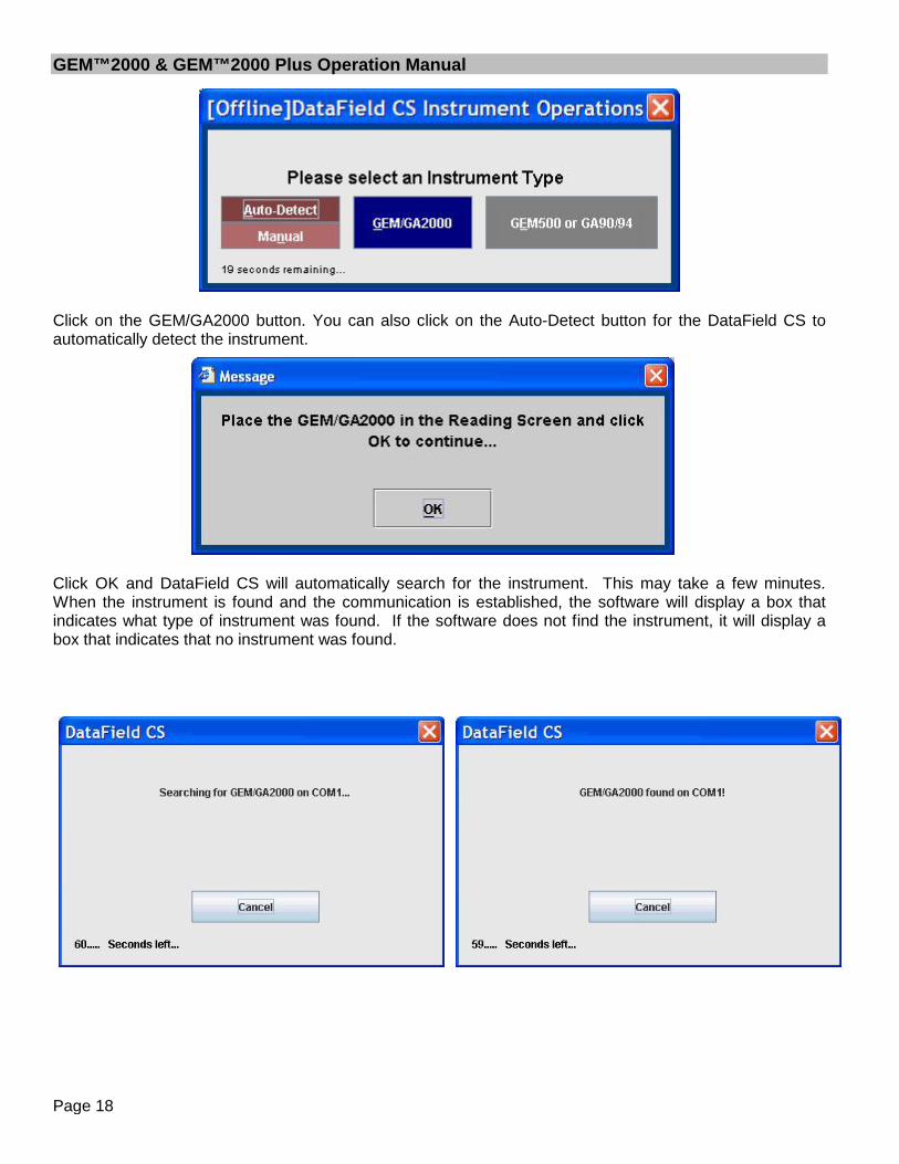
Click on the GEM/GA2000 button. You can also click on the Auto-Detect button for the DataField CS toautomatically detect the instrument.
Click OK and DataField CS will automatically search for the instrument. This may take a few minutes.When the instrument is found and the communication is established, the software will display a box thatindicates what type of instrument was found. If the software does not find the instrument, it will display abox that indicates that no instrument was found.
GEM™2000 & GEM™2000 Plus Operation Manual
Page 19
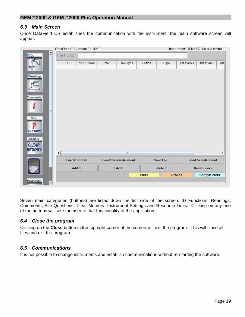
6.3 Main ScreenOnce DataField CS establishes the communication with the instrument, the main software screen willappear.
Seven main categories (buttons) are listed down the left side of the screen: ID Functions, Readings,Comments, Site Questions, Clear Memory, Instrument Settings and Resource Links. Clicking on any oneof the buttons will take the user to that functionality of the application.
6.4 Close the programClicking on the Close button in the top right corner of the screen will exit the program. This will close allfiles and exit the program.
6.5 CommunicationsIt is not possible to change instruments and establish communications without re-starting the software.

GEM™2000 & GEM™2000 Plus Operation Manual
Page 20
6.6 FunctionsEach button has a specific function as listed below:
1. Comments – Allows entry of comments that may be selected for the IDs. A total of sevencomments and one exclusive comment may be selected for each ID.
2. IDs – Used for adding new IDs, editing IDs or deleting IDs and entry of ID parameters such aspump run time, flow device, comments and questions for the ID.
3. Readings – Allows downloading and viewing data from instrument and uploading of previous datato the instrument.
4. Site Questions – DataField CS supports a total of five site questions that are answered by thetechnician and saved to the ID data.
5. Clear Memory – Allows the deletion if selective IDs, readings, comments, site questions or allmemory loaded in instrument memory.
6. Resource Links – Allows the user to directly access information via the www.
6.6.1 CommentsDataField CS allows up to 64 comments to be created for upload to the GEM™2000. Eachcomment may be up to 36 characters in length and may be alphanumeric or any character on thecomputer keyboard. Select Comment or Exclusive Comment must be turned on for commentsto be selected for that ID. See section 6.6.2. Click on the Comments button to open the
following screen.

GEM™2000 & GEM™2000 Plus Operation Manual
Page 21
Enter the comment on the comment line and press Enter to continue entering comments until all thedesired comments have been entered. Click on Save File to save the data to disk and then click on Sendto Instrument to save the comments in the instrument. To delete a comment, click on the comment tohighlight the comment and press the Delete key on the computer keyboard to remove the highlightedcomment. It is always suggested to save the comment file because of the potential size and time requiredto recreate the comments. Once created, the comment file may be modified and saved under a differentfile name at any time.Note: Comments must be created and sent to the instrument through the software. They can not be handinput into the instrument in the field.

GEM™2000 & GEM™2000 Plus Operation Manual
Page 22
6.6.2 Entering IDs
From the opening screen select the ID button. The following screen will open:
Selecting the Save File button will allow you to enter the name for the file you wish to save. The naming offiles follows the extended naming convention for Windows (255 characters maximum, all charactersallowed except \ / : * ? " < > |).
Selecting the Load from File button will allow a previously created file to be loaded from the computer diskdrive.
Selecting the Load from Instrument button will allow previously loaded IDs in the instrument to bedownloaded for modification such as increasing the pump run time or adding additional comments to aspecific ID. CAUTION: Loading IDs from an instrument can be a dangerous practice and is notrecommended if using DF online service. The possibility exists of introducing into a project IDs fromanother project. When the IDs are downloaded from the instrument and stored online all IDs that arepresent in the instrument will be stored to the current project IRRESPECTIVE of if the IDs belong to theproject.

GEM™2000 & GEM™2000 Plus Operation Manual
Page 23
Add ID button is used for the creation of a new ID or multiple IDs that may be sent to the instrument orsaved to a new file for later use.
To enter a new ID or create a new ID set, click on the Add ID button and the following screen will open:
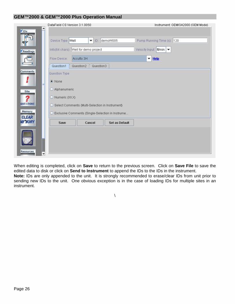
Enter the Well ID in any combination of alpha or numeric characters for a maximum of eight characters. Alleight characters must be used. Enter the pump run time in seconds (maximum of 999 seconds); pumprun time must be entered in order for the pump to be turned on for gas sampling. Enter information aboutthe well, such as its location, previous problems, etc or leave blank. Enter the type of flow device used withthe well (Accu-Flo wellhead, Pitot tube, or orifice plate); user input may also be selected. If Pitot tube ororifice plate is selected, the inside pipe diameter and orifice diameter must be entered. If the pump runtime and the flow device are going to be the same for multiple wells, click on Set as Default to lock thesetwo values. Three questions may be asked about the well for reply by the technician at the time a sampleis taken. These can take the form of alphanumeric, numeric, selected comments or exclusive comments.If none is selected then no questions will be asked for this ID. Note: If Select Comments or ExclusiveComments is selected, Comments must be created and sent to the instrument. See section 6.6.1.
GEM™2000 & GEM™2000 Plus Operation Manual
Page 24
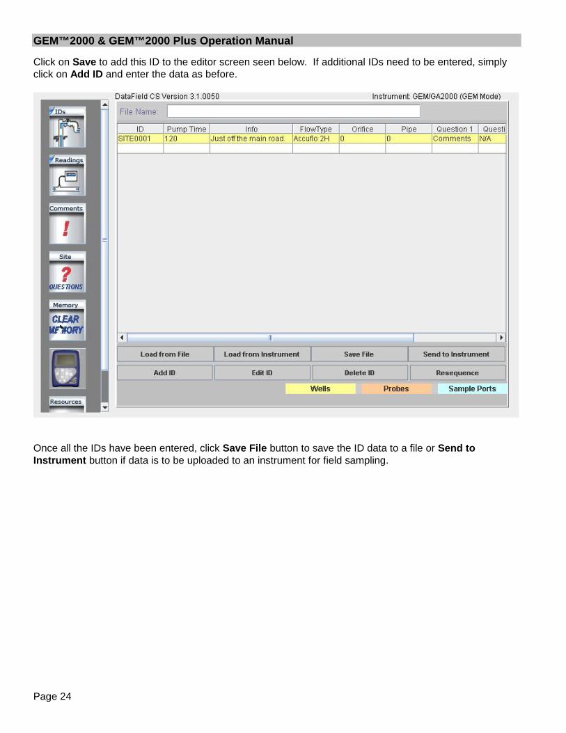
Click on Save to add this ID to the editor screen seen below. If additional IDs need to be entered, simplyclick on Add ID and enter the data as before.
Once all the IDs have been entered, click Save File button to save the ID data to a file or Send toInstrument button if data is to be uploaded to an instrument for field sampling.

GEM™2000 & GEM™2000 Plus Operation Manual
Page 25
6.6.3 Editing IDs
IDs may be edited in a similar manner to entering a new ID. Click on the ID button. Click on the Loadfrom File button if the IDs to be edited are in a saved file on disk or click on Load from Instrument if theIDs to be edited reside in the instrument. Once the IDs have been opened, the ID Editor screen willappear as shown below.
To select an ID for editing, click on the ID to highlight the ID, and then click on the Edit ID button. The EditID screen will open and allow information for the selected ID to be changed. When finished with thechanges, click on Save to save the edited ID to the ID list.
GEM™2000 & GEM™2000 Plus Operation Manual
Page 26
When editing is completed, click on Save to return to the previous screen. Click on Save File to save theedited data to disk or click on Send to Instrument to append the IDs to the IDs in the instrument.Note: IDs are only appended to the unit. It is strongly recommended to erase/clear IDs from unit prior tosending new IDs to the unit. One obvious exception is in the case of loading IDs for multiple sites in aninstrument.
\

GEM™2000 & GEM™2000 Plus Operation Manual
Page 27
6.6.4 Delete IDsSelect an ID to delete and click on it to highlight it. Click on the Delete ID button. A prompt will appear toverify the action. Clicking Yes will delete the ID. To select multiple IDs use Ctrl and Shift buttons on yourkeyboard. When deleting multiple IDs after clicking on the Delete ID button a prompt will appear: “Wouldyou like to verify each deletion?” Clicking No will delete all the selected IDs. Clicking Yes will prompt on thedeletion of each ID in the selection. In this case the deletion of some IDs in the selection can be cancelled.
Click on Save File to save the updated file to disk or click on Send to Instrument to update the instrumentfor field sampling.
Note: We suggest clearing the ID information from the instrument prior to uploading the revised ID list.Otherwise the new ID list will be appended to the existing list. Clearing IDs in the instrument will clear IDsin the both GEM & GA modes of operation.

GEM™2000 & GEM™2000 Plus Operation Manual
Page 28
6.6.5 Re-sequencingWith DataField CS it is possible to change the order of the IDs in a file to put them in the same order asthey are sampled in the field. This is called Re-sequencing. To re-sequence an ID data set, click on the IDbutton to open the ID editor. Load the ID data set from a file or download the data set from the instrument.Click on the Re-sequence button to open the screen shown below.
Select the ID from the left side window and click on the Right button to move ID to the right window tocreate the new sequence order. Repeat this process moving all IDs to the right side in the desired order.

GEM™2000 & GEM™2000 Plus Operation Manual
Page 29
Click OK when the desired new sequence is obtained, this will return you to the well ID screen. Click on theSave File button to save the new data set to a file on disk or click on Send to Instrument to upload thenew data to the instrument.Note: It is suggested to clear ID information from the instrument prior to uploading the re-sequenced ID list.Otherwise the new ID list will be appended to the existing list. Clearing IDs in the instrument will clear IDsin the both GEM & GA modes of operation.

GEM™2000 & GEM™2000 Plus Operation Manual
Page 30
6.6.6 ReadingsThe Readings screen provides the capability to download, upload, view, save data to a file anddelete individual or multiple readings from a data set. Click on the Readings button to open thescreen shown below.
GEM™2000 & GEM™2000 Plus Operation Manual
Page 31
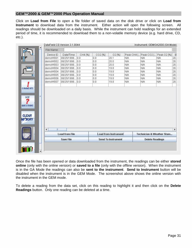
Click on Load from File to open a file folder of saved data on the disk drive or click on Load fromInstrument to download data from the instrument. Either action will open the following screen. Allreadings should be downloaded on a daily basis. While the instrument can hold readings for an extendedperiod of time, it is recommended to download them to a non-volatile memory device (e.g. hard drive, CD,etc.).
Once the file has been opened or data downloaded from the instrument, the readings can be either storedonline (only with the online version) or saved to a file (only with the offline version). When the instrumentis in the GA Mode the readings can also be sent to the instrument. Send to Instrument button will bedisabled when the instrument is in the GEM Mode. The screenshot above shows the online version withthe instrument in the GEM mode.
To delete a reading from the data set, click on this reading to highlight it and then click on the DeleteReadings button. Only one reading can be deleted at a time.

GEM™2000 & GEM™2000 Plus Operation Manual
Page 32
6.6.7 Site QuestionsDataField CS supports up to five site questions. Site questions are answered only when UpdateSite Data is selected from the GEM menu screen and appended to all IDs taken thereafter untilUpdate Site Data is selected again. This is a useful feature if conditions change in variouslocations on the landfill site or for selected wells/probes. Site questions can be either
alphanumeric, numeric, select comment (the technician selects the comment from a list of ten answers) orexclusive comments (the technician may select only ONE exclusive question from a list of 10 answers).From the opening screen, click on the Site Questions button to open the following screen.
Note: Site questions must be created and sent to the instrument by the software prior to going into thefield. They can not be hand inputted into the instrument in the field.
GEM™2000 & GEM™2000 Plus Operation Manual
Page 33
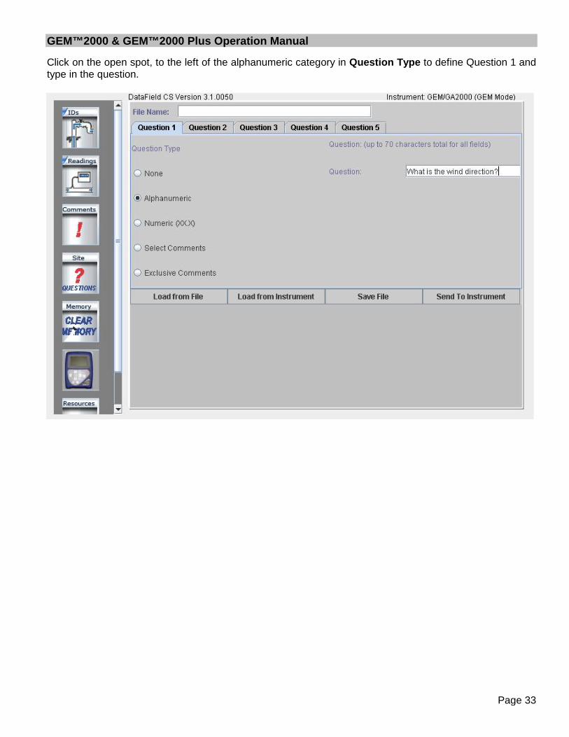
Click on the open spot, to the left of the alphanumeric category in Question Type to define Question 1 andtype in the question.

GEM™2000 & GEM™2000 Plus Operation Manual
Page 34
Click on Question 2 and then select Numeric as the Question Type. Note that Answer Format and Unit ofMeasurement fields appear for this type of question. Answer format refers to the number of digits anddecimal places required for the answer. Unit of Measurement refers to inches, feet, yards, etc. for theanswer. In this example, XX.X could be equal to 20.5 inches as per the question ‘What is the leachatedepth in tank?’

GEM™2000 & GEM™2000 Plus Operation Manual
Page 35
Comments may also be used as a site question; however, comments must be downloaded from aninstrument that already has comments loaded in it. Connect the GEM™2000 / GEM™2000 Plus and besure it is in the read gas screen. Click on Select Comments and the list of comments from the instrumentwill open in the window for selection. Ten comments may be selected from the list to become SiteQuestions. Click on the box to the left of the comment to select it. The operator may choose any or all ofthe ten comments when Update Site Data is selected on the instrument.

GEM™2000 & GEM™2000 Plus Operation Manual
Page 36
Exclusive comments are treated in a similar manner as select comments in that they also must bedownloaded from the instrument. Ten exclusive comments may be selected, however only ONE may bechosen by the operator to become an Exclusive Comment.
When all the desired questions have been entered, click on Save File to retain the information for later useand then click on Send to Instrument to update site data in the instrument.

GEM™2000 & GEM™2000 Plus Operation Manual
Page 37
6.7 SettingsClicking on the Settings button on the main screen will display the Instrument Settings. TheInstrument settings provide the capability to set or change optional controls in the instrument, suchas time/date, data logging (GA mode only), purge times, etc.
6.7.1 Instrument SettingsSet the instrument for RS-232 communications and click on the Settings button and the following screenwill open. The software will establish communications and download the current instrument settings.
Once the current settings have been obtained, the following screen will open.
There are six different “Menu Cards” under instrument settings. Each card provides different information orinstrument settings that may be changed to update the operation of the GEM™2000 / GEM™2000 Plus.The instrument status card will always be shown first, providing calibration and maintenance information inaddition to instrument serial number and software version number.

GEM™2000 & GEM™2000 Plus Operation Manual
Page 38
Click on the card tab for Alarm Levels to open the alarm levels screen. Both a maximum alarm and aminimum alarm may be set. Note these are global settings and will be the same for all IDs entered in theinstrument. Turn off the alarm by clicking off the check mark next to the gas. Click on Update AlarmLevels to send the new settings to the instrument.

GEM™2000 & GEM™2000 Plus Operation Manual
Page 39
Click on the Data Logging card tab to open the data-logging screen. In this screen enter the Logging ID;this may be any alphanumeric combination of eight characters. Enter the interval between readings inminutes and pump run time in seconds. Click on Update Logging Data to send to instrument. Only onelogging ID may be loaded to the instrument.
GEM™2000 & GEM™2000 Plus Operation Manual
Page 40
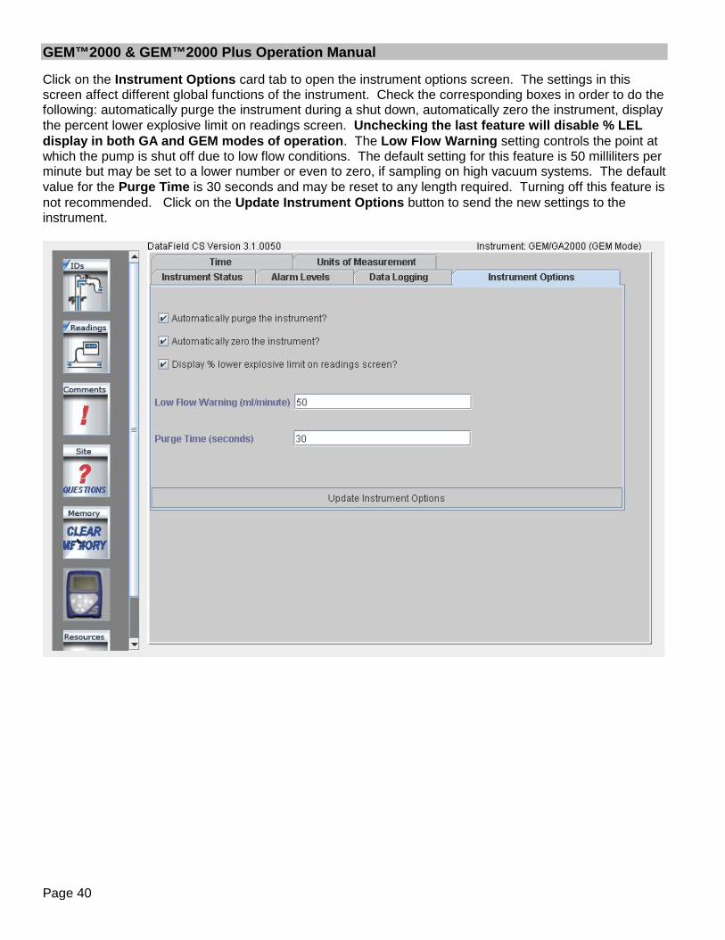
Click on the Instrument Options card tab to open the instrument options screen. The settings in thisscreen affect different global functions of the instrument. Check the corresponding boxes in order to do thefollowing: automatically purge the instrument during a shut down, automatically zero the instrument, displaythe percent lower explosive limit on readings screen. Unchecking the last feature will disable % LELdisplay in both GA and GEM modes of operation. The Low Flow Warning setting controls the point atwhich the pump is shut off due to low flow conditions. The default setting for this feature is 50 milliliters perminute but may be set to a lower number or even to zero, if sampling on high vacuum systems. The defaultvalue for the Purge Time is 30 seconds and may be reset to any length required. Turning off this feature isnot recommended. Click on the Update Instrument Options button to send the new settings to theinstrument.

GEM™2000 & GEM™2000 Plus Operation Manual
Page 41
Click on the Time card tab to open the time and date setting screen. Time and date may be set to thecomputer time and date settings by clicking on the Click to Retrieve the Computer’s Time and Datebutton. Manual setting of the time and date may be accomplished by clicking on the Update InstrumentTime to Above Time and Date. Any time updates must be done through the software. The instrumenttime can not be manually updated in the field.

GEM™2000 & GEM™2000 Plus Operation Manual
Page 42
Units of Measurement screen allows the units to be changed.
This screen is protected by the password. If you need to change the units of measurement, please contactour technical support team.
Note: EXTREME CAUTION should be taken if changing the Units of Measurement. All data from theinstrument should be downloaded and stored in both, the GEM and the GA modes before updating theUnits of Measurement. Updating Units of Measurement will erase readings from the instrument. Theinstrument should be turned off and restarted once the units of measurement have been updated.

GEM™2000 & GEM™2000 Plus Operation Manual
Page 43
6.7.2 Resource Links
Clicking on the Resource Links button on the main screen will display the Resources and Linksscreen.
By clicking on the supplied link the user is taken directly to the www and the information listed.

GEM™2000 & GEM™2000 Plus Operation Manual
Page 44
7 Field Operations
7.1 Landfill Gas GenerationA brief overview of the theory of landfill gas generation and Methane recovery follows. Initially, whendecomposable refuse is placed into a solid waste landfill, the refuse is entrained with air from thesurrounding atmosphere. Through a natural process of bacterial decomposition, the Oxygen from the air isconsumed and an anaerobic (Oxygen free) environment is created within the landfill. This anaerobicenvironment is one of several conditions necessary for the formation of Methane-CH4.
If Oxygen is reintroduced into the landfill, those areas are returned to an aerobic (Oxygen present) stateand the Methane-producing bacteria population is destroyed. A period of time must pass before theproductive capacity is returned to normal. Since there is some Methane of a given quality within the landfillvoid space, a decline in Methane quality is only gradually apparent depending upon the size of the landfill.
Carbon Dioxide is also produced under either an aerobic or anaerobic condition. Under static conditions,the landfill gas will be composed of roughly half Methane and half Carbon Dioxide with a little Nitrogen.
As air is introduced into the landfill, the Oxygen is initially converted to Carbon Dioxide and residualNitrogen remains. Measurement of residual Nitrogen is usually a good indicator of the anaerobic state ofthe landfill; however, it cannot be directly measured. It can, however, be assumed and estimated using asubtraction basis as the balance gas. Hence, the measurement of Carbon Dioxide is an intermediary step.Because Carbon Dioxide levels may fluctuate depending on the changing concentrations of the otherconstituent gases, Carbon Dioxide levels are not evaluated directly but are considered in light of other data.
In evaluation of residual Nitrogen, allowances must be made if there has been any air leakage into the gascollection system or if there has been serious over pull. If enough air is drawn into the landfill, not allOxygen is converted into Carbon Dioxide and the Oxygen is apparent in the sample. It is ideal to performroutine analysis of individual wells, as well as an overall well field composite sample, by a gaschromatography. This is not always practical at every landfill.
Under some conditions there may be a small amount of hydrogen in the LFG, (about 1 percent, usuallymuch less). This may affect field monitoring response factors, but otherwise it can be ignored.
7.2 Subsurface Fires
If very large quantities of air are introduced into the landfill, either through natural occurrence or overlyaggressive operation of the LFG system, a partly unsupported subsurface combustion of the buried refusemay be initiated. Subsurface fire situations are difficult to control or extinguish once started, present healthand safety hazards, and can be quite costly. Therefore, prevention by good operation of the collectionsystem and maintenance of the landfill cover is the best course of action. The presence of CarbonMonoxide, Carbon Dioxide, and Hydrogen Sulfide are indicators of poorly supported combustion within thelandfill.

GEM™2000 & GEM™2000 Plus Operation Manual
Page 45
7.3 Techniques for Controlling Landfill Gas
There are many techniques for controlling landfill gas extraction. These techniques represent tools, whichare used together to control landfill gas. The Accu-Flo wellhead is designed to work with all of thesetechniques. Below is a discussion of the individual techniques, how to use them, and their limitations.Reliance on only a few of the techniques discussed can lead to misinterpretation of field data and improperoperation of the well field. Later the best use of these techniques to optimize landfill gas control will bediscussed.
7.3.1 Controlling by Wellhead Valve Position
Unless the valve handle is calibrated for a given flow rate, this method is unreliable. The position of thevalve handle alone does not provide sufficient information about the well to control it. It is useful to note therelative position of the valve, and essential to know which valves are fully open or fully closed.
7.3.2 Controlling by Wellhead Vacuum
This technique relies on the relationship of well pressure/vacuum to flow for a given well. Reliance uponthis method, however, can be misleading. This is because the square root relationship between flow andpressure is difficult to affect while performing day-to-day well field adjustments. As decomposition,moisture, and other conditions change, this method shows itself to be inadequate and imprecise.
7.3.3 Controlling by Gas Composition
This method determines Methane, Nitrogen (balance gas) and other gas composition parameters atwellheads and at recovery facilities using portable field instruments and, sometimes, analytical laboratoryequipment. Complete knowledge of gas composition (i.e., major fixed gases: Methane, Carbon Dioxide,Oxygen and Nitrogen) is desirable. It is also necessary to check other gas parameters, such as CarbonMonoxide, to fully evaluate the condition of the well field. Reliance on this information can lead to improperoperation of the well field. Indications of excessive extraction often do not show up right away. Thismethod often leads to a cycle of damage to the Methane producing bacteria population and then to over-correction. This cycling of the well and producing area of the landfill is not a good practice. It leads tofurther misinterpretation of the condition of the well field and has a disruptive effect on the operation of thewell field. The use of analytical laboratory instrumentation such as a gas chromatograph is a valuablesupplementary tool to verify gas composition. This normally requires collection of samples at the wellheadand analysis at some fixed location where the equipment is located. The drawbacks of this method as aprimary means of obtaining information for well field adjustment are the time expended, cost, and probablymost important, responsiveness to the needs of the well field for timely adjustment. The laboratoryequipment required is also very costly. Some analysis is recommended for verification of field readingsfrom time to time. It is recommended a monthly sample of the composite gas be taken at the inlet to theflare or gas recovery facility.
7.3.4 Controlling by Flow Rate
This is a more exacting technique for determining and adjusting gas flow at individual wells. It requiresusing a fixed or portable flow measurement device at each wellhead to obtain the data needed to calculatevolumetric (or mass) flow rates. It is normally convenient to use cubic feet per minute or per day, as astandard unit of measure for volumetric flow. It is important to distinguish between the volumetric quantity

GEM™2000 & GEM™2000 Plus Operation Manual
Page 46
of landfill gas and the volumetric quantity of Methane extracted from each well and the landfill in total. Thetwo variables are somewhat independent of each other and it is the total quantity of Methane extracted weare interested in. It is possible for the total quantity of landfill gas extracted to increase while the totalquantity of Methane extracted decreases. To monitor this, the quantity of Methane extracted (LFG flow xpercent Methane) or the quantity of BTUs recovered per hour (LFG flow x percent Methane x BTUs percubic foot of Methane x 60 minutes per hour) can be calculated. It is conventional to measure BTUs perhour as a unit of time. There are approximately 1012 BTUs of heat per cubic foot of pure Methane (likenatural gas), although this figure varies a little among reference texts.
Measuring flow is an essential part of monitoring and adjusting a well field. The well should be adjusteduntil the amount of Methane recovered is maximized for the long term. A greater amount of Methane orenergy can usually be recovered over the short term; however, this ultimately leads to diminishing returns.This is seen in stages as increased CO2 and gas temperature and later as increased Oxygen from wellover-pull. In time, the Methane will also decline. This is the result of a portion of the landfill, usually at thesurface, being driven aerobic. In this portion of the landfill, the Methane-producing bacteria will have beendestroyed (due to the presence of Oxygen). With the Methane-producing capacity of the landfill reduced,the pore space in the area no longer producing may become filled with landfill gas equilibrating (moving in)from an unaffected producing area. This leaves the impression that more gas can be recovered from thisarea, and may lead to the operator opening the well or increasing flow.
7.4 Well field Monitoring
The frequency of LFG well field monitoring varies depending upon field requirements and conditions.Normal monitoring frequency for a complete field monitoring session with full field readings (suggestednormal and abbreviated field readings list follows) will vary from typically once a month to once a week.Well field monitoring should not normally be extended beyond one month. The importance of regular,timely monitoring cannot be overemphasized.
7.5 Typical Field Readings
Name of person taking readings Date/time of each reading Methane (CH4) Oxygen (O2) Carbon Dioxide (CO2) Balance Gas (primarily Nitrogen N2) Wellhead gas temperature (flowing) Ambient air temperature Static pressure (PS) (from GEM™2000 or magnehelic) or other device(anemometer/velometer) Velocity head (P or PT) (from GEM™2000 or pitot tube and magnehelic) Wellhead gas flow (from GEM™2000, or pitot tube & magnehelic, or anemometer/velometer) Wellhead adjustment valve position (initial and adjusted) New wellhead vacuum and flow information after adjustment Calculation of each well’s LFG and Methane flow and sum total Observations/comments
Additionally, Carbon Monoxide (CO) or Hydrogen Sulfide (H2S) readings may be taken if problems aresuspected. Supplementary monitoring once to several times a week may be performed using anabbreviated form of field readings.

GEM™2000 & GEM™2000 Plus Operation Manual
Page 47
7.6 Abbreviated Field Readings
Name of person taking readings Date/time of each reading Methane (CH4) Oxygen (O2) Wellhead gas temperature (flowing) Ambient air temperature Static pressure (PS) (from GEM™2000 or magnehelic) Velocity head (P or Pt) (from GEM™2000 or pitot tube and magnehelic) Wellhead gas flow (from GEM™2000, or pitot tube and magnehelic, or anemometer/velometer) Wellhead adjustment valve position (initial and adjusted) New wellhead vacuum and flow information after adjustment Observations/comments
Line vacuums and gas quality may be taken at key points along the main gas collection header and atsubordinate branches. This helps to identify locations of poor performance, excessive pressure drop, orleakage. Perform systematic monitoring of the well field, taking and logging measurements at eachwellhead and major branch junction in the collection system.
During monitoring, examine landfill and gas collection system for maintenance issues. Record neededmaintenance or unusual conditions. Examples of unusual occurrences or conditions are unusualsettlement, signs of subsurface fires, cracks and fissures, liquid ponding, condensate/leachate weepingfrom side slopes, surface emissions and hot spots, and liquid surging and blockage in the gas collectionsystem. Field readings should be kept in a chronological log and submitted to management on a timelybasis.
7.7 Well field Adjustment Criteria
There are several criteria used in well field adjustment. The primary criterion is Methane quality. Methanequality is an indicator of the healthy anaerobic state of the landfill and thus proper operation of the LFGcollection system. However, a decline in the healthy productive state of the landfill is usually notimmediately apparent from Methane quality. Due to this, several criteria must be considered at once.
Conditions within the landfill favor Methane production. Following are well field adjustment criteria andtypical conditions for consideration:
Methane quality (ranging from 26 percent upwards) pH Temperature General overall quality Moisture conditions Waste stream characteristics Placement chronology Insulation characteristics Oxygen quality (ranging below 1 percent, preferably less then ½ percent) Landfill cover porosity and depth in the proximity of the well Landfill construction factors including: Type of fill Size and shape of refuse mass

GEM™2000 & GEM™2000 Plus Operation Manual
Page 48
Depth of fill Compaction Leachate control methods Seasonal, climatic, geographical, and recent weather, or other considerations, including
seasonally arid or wet conditions, precipitation, drainage, groundwater Surrounding topography and geologic conditions Proximity of the well to side slopes (within 150 to 200 feet and less may require conservative
operation of the well) Nitrogen (typically 8 to 12 percent and less) Temperature (between ambient and about 130 °F) LFG and Methane flow from the wellhead Design of the gas collection system Landfill perimeter gas migration and surface emission control, or energy recovery objectives Diurnal fluctuation (day to night) of atmospheric pressure
7.8 Establishing Target Flows
The goal is to establish a target flow which will likely produce the best possible Methane quality andminimum Oxygen levels while maximizing the recovery of landfill gas. Typically, small adjustments aremade in flow to achieve and maintain quality objectives. The well must not be allowed to over pull. Highwell temperatures, (130 to 140F and greater), are an indication of aerobic activity and, thus, well over-pull.These effects may not be immediately apparent.
Well adjustment should be made in as small an increment as possible, preferably an increment of tenpercent of the existing flow or less. There may be obvious conditions when this is not appropriate, such aswhen first opening up a well or when serious over-pull is recognized. Every effort should be made to makeadjustments and operations as smooth as possible. Dramatic adjustments, or operating while switchingbetween a high flow mode and a well shutoff mode, should be avoided.
7.9 Well field Optimization
Every effort should be made to continuously locate and correct or eliminate conditions (e.g., gascondensate, surging and blockage, settlement, etc.), which inhibit efficient operation of the gas collectionsystem. This allows well monitoring and adjustment to be significantly more effective.
7.10 Migration Control—Dealing with Poor Methane Quality
If Methane and Oxygen quality objectives cannot be maintained at a given well, such as a perimetermigration control well, then an attempt should be made to stabilize the well as closely as is practical,avoiding significant or rapid down trending of Methane or up trending of Oxygen.
It is not uncommon for perimeter migration control wells to be operated at less than 40 percent Methane orgreater than one-percent Oxygen. It should be recognized that these wells are likely in a zone where someaerobic action is being induced, and that there is some risk of introducing or enhancing the spread of asubsurface fire. Sometimes a judicious compromise is necessary to achieve critical migration controlobjectives or because existing conditions do not allow otherwise. Such situations should be monitoredclosely.

GEM™2000 & GEM™2000 Plus Operation Manual
Page 49
7.11 Well field Adjustment—Purpose and Objectives
The objective of well field adjustment is to achieve a steady state of operation of the gas collection systemby stabilizing the rate and quality of extracted LFG in order to achieve one or several goals. Typicalreasons for recovery of LFG and close control of the well field are:
Achieve and maintain effective subsurface gas migration control. Achieve and maintain effective surface gas emissions control. Assist with proper operation of control and recovery equipment. Avoid well “over-pull” and maintain of a healthy anaerobic state within the landfill. Optimize LFG recovery for energy recovery purposes. Control nuisance landfill gas odors. Prevent or control subsurface LFG fires. Protect structures on and near the landfill. Meet environmental and regulatory compliance requirements.
Well field adjustment is partly subjective and can be confusing because it involves judgment calls based onsimultaneous evaluation of several variables, as well a general knowledge of site specific field conditionsand historical trends. Well field evaluation and adjustment consist of a collection of techniques, which maybe used, in combination, to achieve a steady state of well field operation.

GEM™2000 & GEM™2000 Plus Operation Manual
Page 50
8 Troubleshooting
Unit does not turn on or operation is erratic Battery charge is too low-recharge batteries.Unit is too hot - cool down unit and try again.Contact Factory Service.
“Flow Fail” is displayed and an audible alarmis heard
The inlet is blocked.Remove blockage and retry.The particulate filter or water trap filter needs replacing.
Readings taken are not what was expected Unit may be out of calibration. Calibrate unit withknown gas concentration.Water trap or particulate filters are clogged. Replacefilter(s).
Readings swing up or down wildly as they arebeing taken
Cell phones and other sources of RF interference canaffect Methane readings. Don’t use your cell phonewhile taking readings.
Unit displays***** or >>>>> These symbols are substituted when the measuredreading is out of range of the instruments capabilities insome fields or when a value needs to be enteredmanually such as temperature.
Oxygen reading is high on all wells Check that the water trap housing is screwed on tight.Check or replace O-rings on the water trap andinstrument inlet.Check the wellhead inset for cracks, replace O-ring oninsert.Field calibrate Oxygen channel.
Unit will not download readings or an erroroccurs while downloading.
Verify that the communications software is the rightversion for the instrument being used.Check that the proper serial port is selected in thesoftware.Contact Factory Service.
Methane and Carbon Dioxide readings drift Perform a field calibration and check well again. Verifycal gas is flowing when regulator is turned on.Verify all connections are tight and filters are notclogged.Contact Factory Service.
Oxygen readings drift Perform a field calibration - zero and span.Contact Factory Service.
Black screen displayed when unit turned On Charge unit over night and try again.Unit too hot - cool down and try again.Try adjusting contrast level.Contact Factory Service.
Nothing happens when the Gas Pod isinstalled
Remove and re-seat the Gas Pod.Contact Factory Service.
Temperature does not update whentemperature probe is installed
Check the probe fitting is fully seated.Check the probe plug is screwed together tightly.Contact Factory Service.
Problem Corrective Action/Reason

GEM™2000 & GEM™2000 Plus Operation Manual
Page 51
9 Technical Specifications
9.1 PhysicalWeight 4.4 lbs.Size L 2.48” x W 7.48’’ x D 9.92”.Case material Anti-static ABS.Keys Membrane panel.Display Liquid Crystal Display 40 x 16 characters. Fiber optic woven
backlight for low light conditions.Filters User replaceable integral fiber filter at inlet port and external
PTFE water trap filter.
9.2 GeneralCertifications UL Certified to Class 1, Zone 1, AEx Ib d IIa T4Temperature measurement With optional probe 14°F to 167F.Temperature accuracy ±0.4ºF (± probe accuracy).Visual and audible alarm User selectable CO2, CH4 and O2 Min/Max levels via DataField
CS software.Communications RS232 protocol via download lead with variable baud rate.Relative pressure ±250 mbar from calibration pressure
9.3 Power supplyBattery type Rechargeable Nickel Metal Hydride battery pack containing six
4AH cells. Not user replaceable.Lithium Manganese battery for data retention.
Battery life Typical use 10 hours from fully charged condition.Battery charger Separate intelligent 2A battery charger powered from AC
voltage supply (110-230V).Charge time Approximately 2 hours from complete discharge.Alternative power Can be powered externally for fixed-in-place applications only.
Contact LANDTEC for further information.Battery lifetime Up to 1,000 charge/discharge cycles.
9.4 Gas RangesDetection principle CO2 and CH4 by dual wavelength infrared cell with reference
channel.O2 by internal electrochemical cell.
Oxygen cell lifetime Approximately 18 months in air.Typical Accuracy0 - Full Scale
Gas 0-5% volume 5-15% volume 15%-FSCH4 ±0.3% ±1% ±3% (100%)CO2 ±0.3% ±1% ±3% (60%)O2 ±1% ±1% ±1% (21%)
Response time, T90 CH4 20 secondsCO2 20 secondsO2 20 seconds
Range CH4 0-70% to specification, 0-100% reading.CO2 0-40% to specification, 0-100% reading.O2 0-25%

GEM™2000 & GEM™2000 Plus Operation Manual
Page 52
9.5 PumpTypical flow 300 cc/min.Flow fail point 50 cc/min approximately.Flow with 200 mbar vacuum 250 cc/min approximately.Vacuum 70 inches H20.
9.6 Operating ConditionsOperating temp range 32°F to 104F.Relative humidity 0-95% non-condensing.Atmospheric pressure range 700-1200 mbar.
Displayed in Inches of Mercury (5.9 – 35.4“Hg).Not corrected for sea level.
Atmospheric pressure accuracy ±5 mbar approximately.Case seal IP65.
9.7 Optional Gas PodsTypical Accuracy(Subject to User calibration).
Gas 0-Full ScaleCO ±10% FSH2S ±10% FSSO2 ±10% FSNO2 ±10% FSCL2 ±10% FSH2 ±10% FSHCN ±10% FS
Response time, T90 CO 60 secondsH2S 60 secondsSO2 60 secondsNO2 60 secondsCL2 60 secondsH2 60 secondsHCN 60 seconds
Range CO 0-500ppmH2S 0-50 or 0-200ppmSO2 0-20 or 0-100ppmNO2 0-20ppmCL2 0-20ppmH2 0-1000ppmHCN 0-100ppm


