12
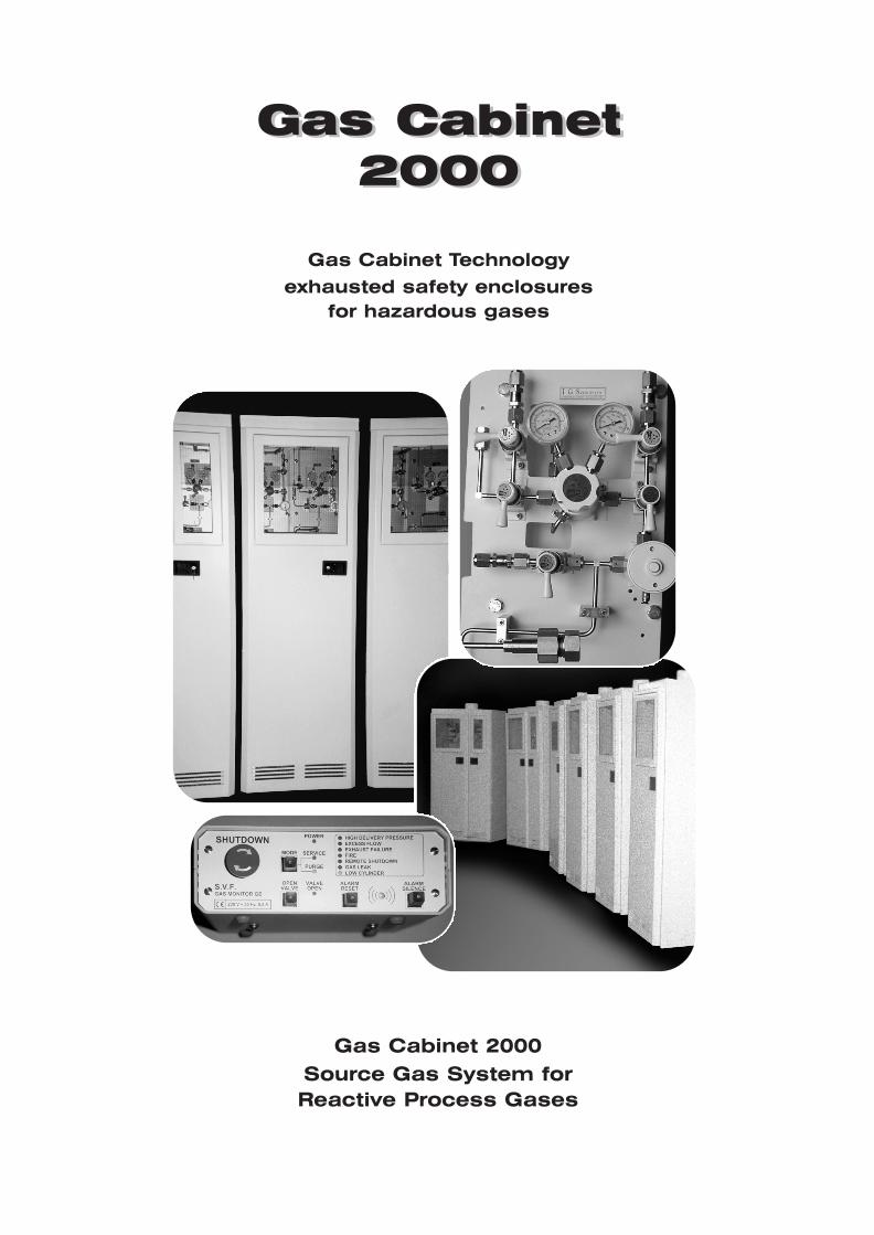
Gas Cabinet 2000 Gas Cabinet 2000 Gas Cabinet Technology exhausted safety enclosures for hazardous gases Gas Cabinet 2000 Source Gas System for Reactive Process Gases
Gas Cabinet2000
Gas Cabinet2000
Gas Cabinet Technology
exhausted safety enclosuresfor hazardous gases
Gas Cabinet 2000Source Gas System forReactive Process Gases
2
* Maximum flow is with fully-open damper on door. Minimum is with closed damper.Exhaust sizing should be based on maximum flow.
Minimum static pressure requirement at cabinet exhaust is 10mm V.P.
Door Closer
Face Shield
Cylinder Bracket
Plenum
Filter
Floor Material
Fire Sprinkler Head
Window
Steel Construction
Door
Cylinder Shelf
Cylinder Scale ramp
Differential Pressure
Switch
Temperature Switch
Fire Detector
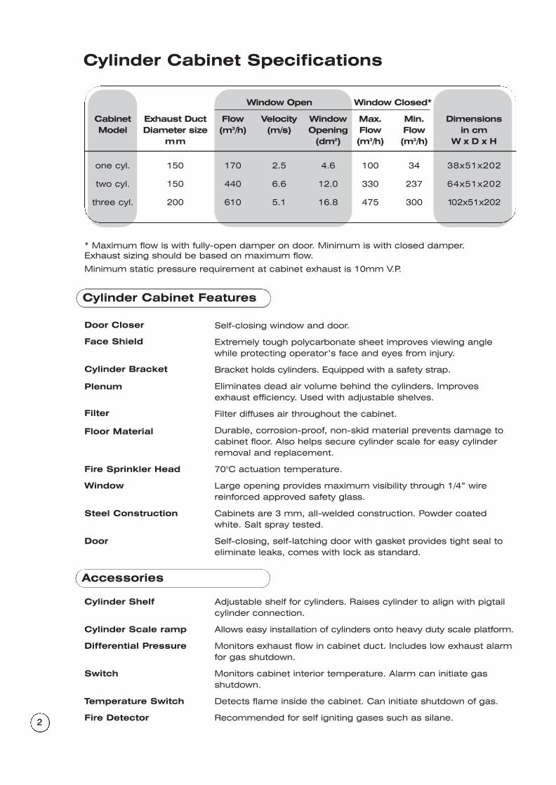
Cylinder Cabinet Specifications
Window Open Window Closed*
Cabinet Exhaust Duct Flow Velocity Window Max. Min. DimensionsModel Diameter size (m3/h) (m/s) Opening Flow Flow in cm
mm (dm2) (m3/h) (m3/h) W x D x H
one cyl. 150 170 2.5 4.6 100 34 38x51x202
two cyl. 150 440 6.6 12.0 330 237 64x51x202
three cyl. 200 610 5.1 16.8 475 300 102x51x202
Cylinder Cabinet Features
Self-closing window and door.
Extremely tough polycarbonate sheet improves viewing anglewhile protecting operator’s face and eyes from injury.
Bracket holds cylinders. Equipped with a safety strap.
Eliminates dead air volume behind the cylinders. Improvesexhaust efficiency. Used with adjustable shelves.
Filter diffuses air throughout the cabinet.
Durable, corrosion-proof, non-skid material prevents damage tocabinet floor. Also helps secure cylinder scale for easy cylinderremoval and replacement.
70°C actuation temperature.
Large opening provides maximum visibility through 1/4” wire reinforced approved safety glass.
Cabinets are 3 mm, all-welded construction. Powder coatedwhite. Salt spray tested.
Self-closing, self-latching door with gasket provides tight seal toeliminate leaks, comes with lock as standard.
Adjustable shelf for cylinders. Raises cylinder to align with pigtailcylinder connection.
Allows easy installation of cylinders onto heavy duty scale platform.
Monitors exhaust flow in cabinet duct. Includes low exhaust alarmfor gas shutdown.
Monitors cabinet interior temperature. Alarm can initiate gas shutdown.
Detects flame inside the cabinet. Can initiate shutdown of gas.
Recommended for self igniting gases such as silane.
Accessories
3
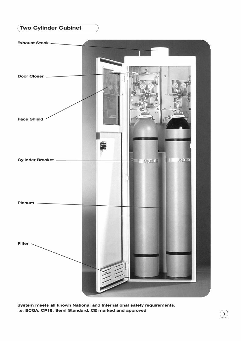
Two Cylinder Cabinet
Door Closer
Face Shield
Cylinder Bracket
Plenum
Filter
Exhaust Stack
System meets all known National and International safety requirements.i.e. BCGA, CP18, Semi Standard. CE marked and approved
4
Component Features
Technical Data
Regulator with pressurerelief valve
Pigtail
Inlet filter
High Pressure Isolation(HPI) valve
High Pressure Ventilation(HPV) valve
Low Pressure Ventilation(LPV) valve
Low Pressure Isolation(LPI) valve
Check valve
Purge Gas Inlet (PGI)valve
Pneumatic EmergencyShut-off (ESO) valve
Excess Flow Switch(EFS)
Regulator relief valve protects low pressure downstreamcomponents if delivery pressure exceeds gauge maximum pressure.
Enables reliable, flexible connection to gas cylinder valve, permitting vertical adjustment of ± 50 mm. Pigtail design andconfiguration is specific for each gas.
Stainless steel 0.4µ high pressure pre filter protects systemcomponents from contamination and damage by paniculatematter.
2-way, 3-port valve isolates regulator and low-pressure side ofmanifold from purge gas during purging operations.
Ventilates process gas from high pressure side of manifold duringpurging operations and in emergencies.
Used during cylinder change to enable ventilation of process gasat reduced pressure. Also enables maintenance purge ofregulator and downstream process lines.
This valve isolates gas panel from downstream processequipment. Enables manifold and regulator to be purged withoutcontamination of downstream process gas lines.
Prevents backflow of gases into gas panel.
Controls flow of purge gas into pigtail and manifold duringpurging. Check valve prevents backflow of process gas to purgegas source.
Pneumatically operated, normally closed valve enables manualshutdown of process gas flow. ESO valve is typically actuated byan IGS gas monitor (Model GM-1 or GM-6), automatically shuttingoff gas in case of excess flow, exhaust system failure, fire or iftoxic gas is detected. (Option)
Shuts off flow by sending a signal to an IGS Gas Monitor(GB 6), which then closes the ESO valve. (Option)
Max. Outlet Wetted Wetted Working Dim.inlet pressure pressure regulator material valve material temp. mm
240 bar 0 – 2 bar Body 316 L SS Body 316 L SS -40˚C W=280
0 – 7 bar Seal Kel-F 81 Seal Kel-F 81 to H=540
Diaph.316 L SS Diaph. Elgiloy +65˚C D=170
5
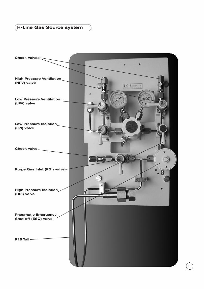
H-Line Gas Source system
High Pressure Ventilation(HPV) valve
Low Pressure Ventilation(LPV) valve
Low Pressure Isolation(LPI) valve
Check valve
Purge Gas Inlet (PGI) valve
High Pressure Isolation(HPI) valve
Pneumatic EmergencyShut-off (ESO) valve
P16 Tail
Check Valves
6
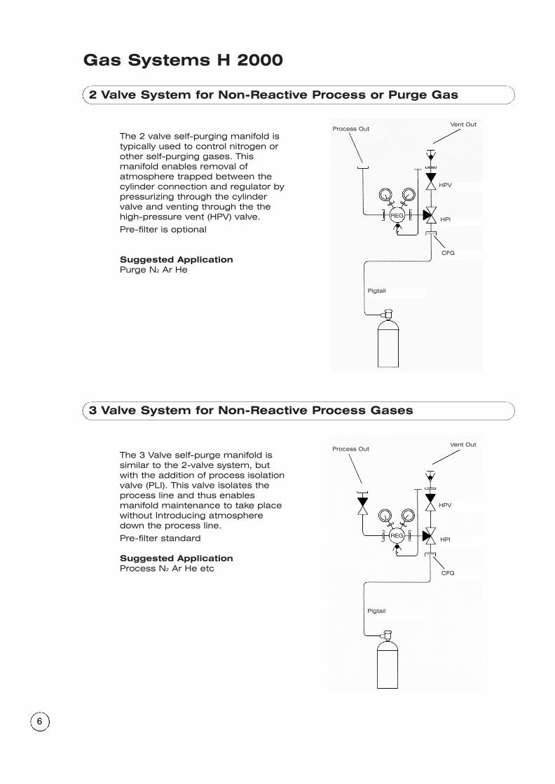
Gas Systems H 2000
2 Valve System for Non-Reactive Process or Purge Gas
The 2 valve self-purging manifold istypically used to control nitrogen orother self-purging gases. Thismanifold enables removal of atmosphere trapped between thecylinder connection and regulator bypressurizing through the cylindervalve and venting through the thehigh-pressure vent (HPV) valve.
Pre-filter is optional
Suggested ApplicationPurge N2 Ar He
3 Valve System for Non-Reactive Process Gases
The 3 Valve self-purge manifold issimilar to the 2-valve system, butwith the addition of process isolationvalve (PLI). This valve isolates theprocess line and thus enablesmanifold maintenance to take placewithout Introducing atmospheredown the process line.
Pre-filter standard
Suggested ApplicationProcess N2 Ar He etc
Pigtail
CFG
Vent Out Process Out
HPV
HPIREG
Pigtail
CFG
Vent Out Process Out
HPV
HPIREG
7
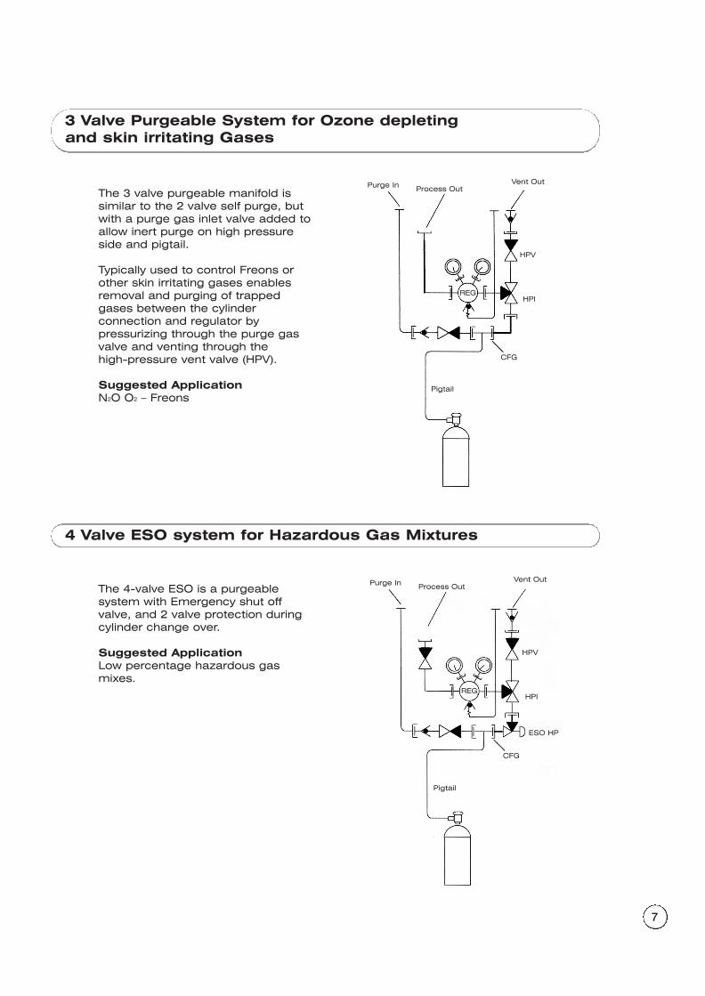
3 Valve Purgeable System for Ozone depletingand skin irritating Gases
4 Valve ESO system for Hazardous Gas Mixtures
The 3 valve purgeable manifold issimilar to the 2 valve self purge, butwith a purge gas inlet valve added toallow inert purge on high pressureside and pigtail.
Typically used to control Freons orother skin irritating gases enablesremoval and purging of trappedgases between the cylinderconnection and regulator bypressurizing through the purge gasvalve and venting through the high-pressure vent valve (HPV).
Suggested ApplicationN2O O2 – Freons
The 4-valve ESO is a purgeable system with Emergency shut offvalve, and 2 valve protection duringcylinder change over.
Suggested ApplicationLow percentage hazardous gasmixes.
Pigtail
CFG
Vent Out Process OutPurge In
HPV
HPIREG
Pigtail
CFG
ESO HP
Vent Out Process OutPurge In
HPV
HPIREG
8
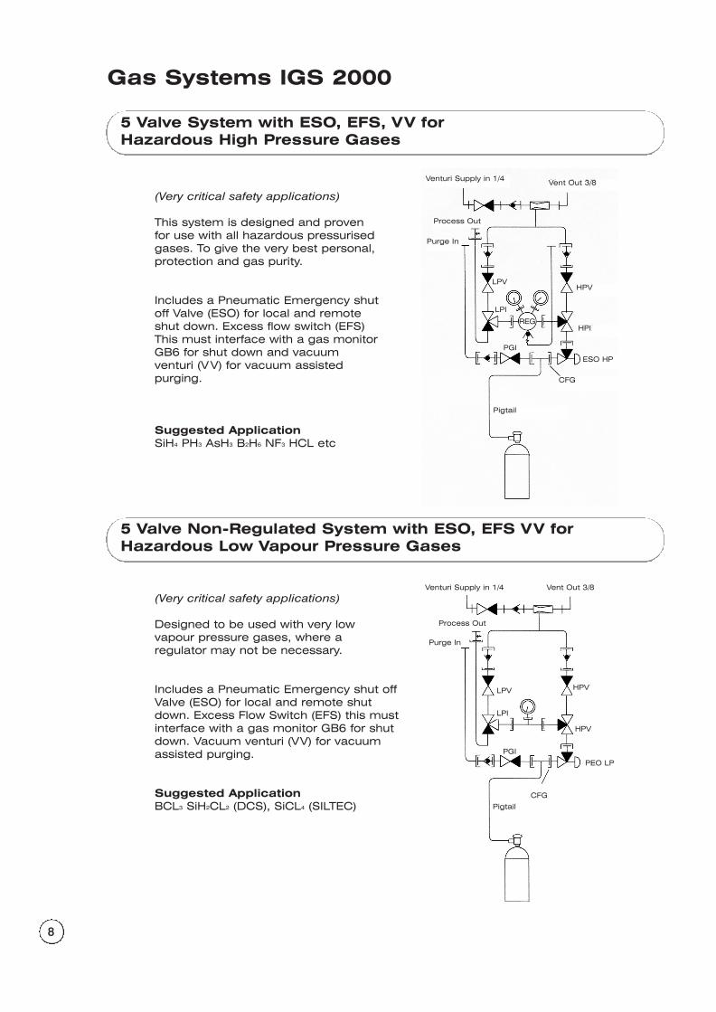
5 Valve System with ESO, EFS, VV forHazardous High Pressure Gases
5 Valve Non-Regulated System with ESO, EFS VV forHazardous Low Vapour Pressure Gases
(Very critical safety applications)
This system is designed and provenfor use with all hazardous pressurisedgases. To give the very best personal,protection and gas purity.
Includes a Pneumatic Emergency shutoff Valve (ESO) for local and remoteshut down. Excess flow switch (EFS)This must interface with a gas monitorGB6 for shut down and vacuum venturi (VV) for vacuum assistedpurging.
Suggested ApplicationSiH4 PH3 AsH3 B2H6 NF3 HCL etc
(Very critical safety applications)
Designed to be used with very lowvapour pressure gases, where aregulator may not be necessary.
Includes a Pneumatic Emergency shut offValve (ESO) for local and remote shutdown. Excess Flow Switch (EFS) this mustinterface with a gas monitor GB6 for shutdown. Vacuum venturi (VV) for vacuumassisted purging.
Suggested ApplicationBCL3 SiH2CL2 (DCS), SiCL4 (SILTEC)
Gas Systems IGS 2000
Pigtail
CFG
HPVLPV
LPI
HPI
PGI
ESO HP
Vent Out 3/8Venturi Supply in 1/4
Process Out
Purge In
REG
Pigtail
CFG
HPV
HPVLPV
LPI
PGI
PEO LP
Vent Out 3/8Venturi Supply in 1/4
Process Out
Purge In
9
Process Out
EFS
HP1
PG1
REG
HPV
VV
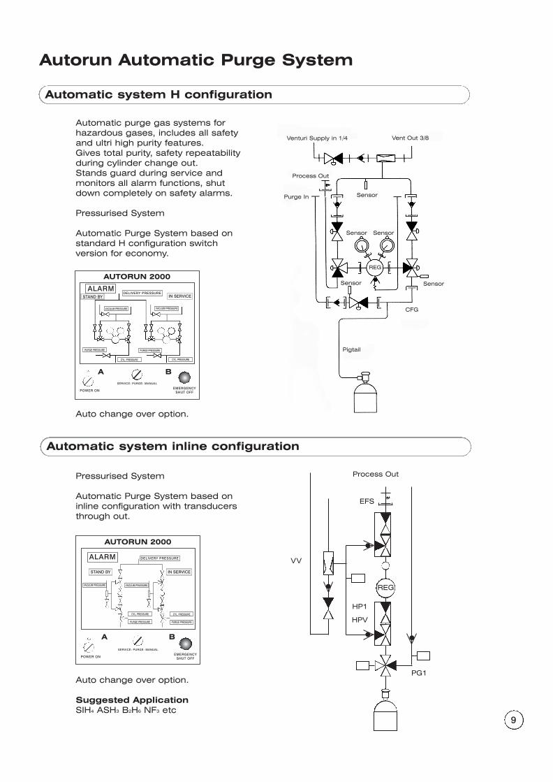
Autorun Automatic Purge System
Automatic purge gas systems forhazardous gases, includes all safetyand ultri high purity features.Gives total purity, safety repeatabilityduring cylinder change out.Stands guard during service andmonitors all alarm functions, shutdown completely on safety alarms.
Pressurised System
Automatic Purge System based onstandard H configuration switch version for economy.
Auto change over option.
Pressurised System
Automatic Purge System based oninline configuration with transducersthrough out.
Auto change over option.
Suggested ApplicationSIH4 ASH3 B2H6 NF3 etc
ALARM
AUTORUN 2000
STAND BY IN SERVICE
DELIVERY PRESSURE
POWER ONEMERGENCY
SHUT OFF
SERVICE: PURGE: MANUAL
VACUUM PRESSURE VACUUM PRESSURE
PURGE PRESSUREPURGE PRESSURE
CYL. PRESSURECYL. PRESSURE
A B
AUTORUN 2000
POWER ONEMERGENCY
SHUT OFF
SERVICE: PURGE: MANUAL
A B
ALARMSTAND BY IN SERVICE
DELIVERY PRESSURE
CYL. PRESSURECYL. PRESSURE
VACUUM PRESSURE VACUUM PRESSURE
PURGE PRESSUREPURGE PRESSURE
Automatic system H configuration
Automatic system inline configuration
REG
Pigtail
CFG
Vent Out 3/8Venturi Supply in 1/4
Process Out
Purge In
Sensor
Sensor
Sensor
Sensor Sensor
A B
10
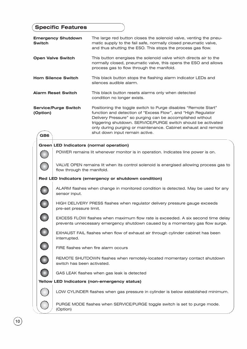
Specific Features
Emergency ShutdownSwitch
Open Valve Switch
Horn Silence Switch
Alarm Reset Switch
Service/Purge Switch(Option)
The large red button closes the solenoid valve, venting the pneu-matic supply to the fail safe, normally closed pneumatic valve,and thus shutting the ESO. This stops the process gas flow.
This button energises the solenoid valve which directs air to thenormally closed, pneumatic valve, this opens the ESO and allowsprocess gas to flow through the manifold.
This black button stops the flashing alarm indicator LEDs andsilences audible alarm.
This black button resets alarms only when detected condition no longer exists.
Positioning the toggle switch to Purge disables “Remote Start”function and detection of “Excess Flow”, and “High RegulatorDelivery Pressure” so purging can be accomplished withouttriggering shutdown. SERVICE/PURGE switch should be activatedonly during purging or maintenance. Cabinet exhaust and remoteshut down input remain active.
Green LED Indicators (normal operation)
GB6
POWER remains lit whenever monitor is in operation. Indicates line power is on.
VALVE OPEN remains lit when its control solenoid is energised allowing process gas toflow through the manifold.
ALARM flashes when change in monitored condition is detected. May be used for anysensor input.
HIGH DELIVERY PRESS flashes when regulator delivery pressure gauge exceeds pre-set pressure limit.
EXCESS FLOW flashes when maximum flow rate is exceeded. A six second time delayprevents unnecessary emergency shutdown caused by a momentary gas flow surge.
EXHAUST FAIL flashes when flow of exhaust air through cylinder cabinet has beeninterrupted.
FIRE flashes when fire alarm occurs
REMOTE SHUTDOWN flashes when remotely-located momentary contact shutdownswitch has been activated.
GAS LEAK flashes when gas leak is detected
LOW CYLINDER flashes when gas pressure in cylinder is below established minimum.
PURGE MODE flashes when SERVICE/PURGE toggle switch is set to purge mode.(Option)
Red LED Indicators (emergency or shutdown condition)
Yellow LED Indicators (non-emergency status)
11
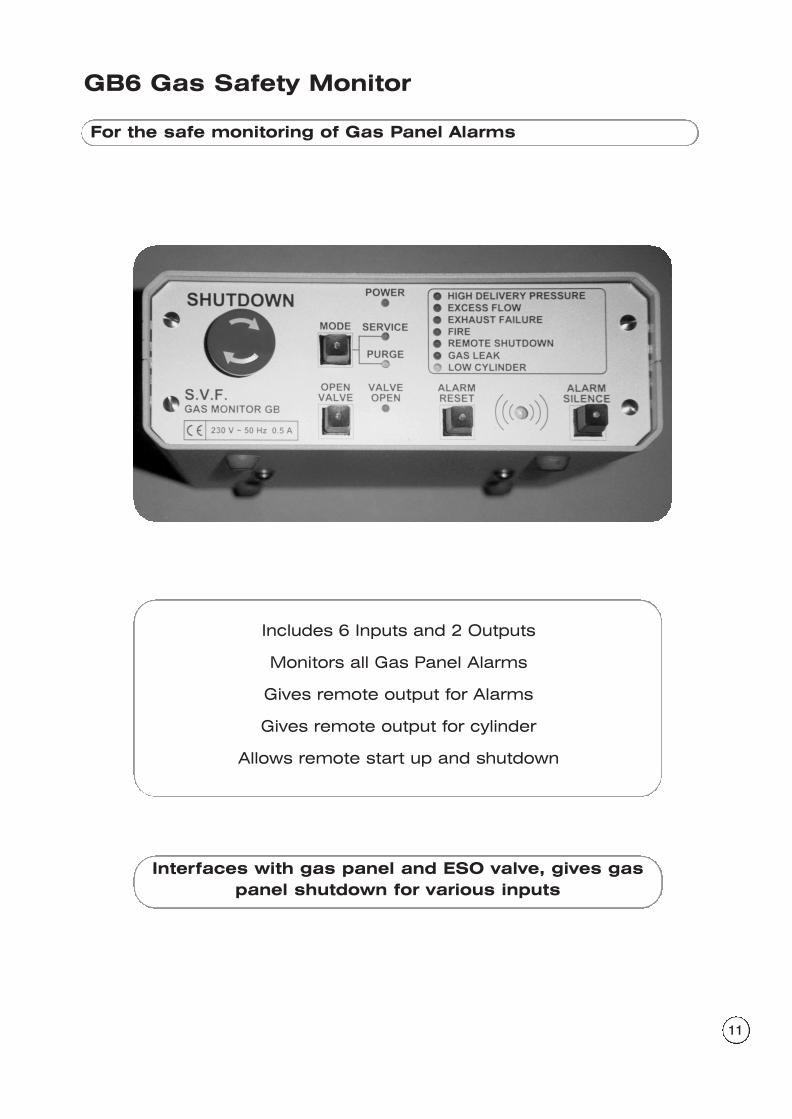
GB6 Gas Safety Monitor
For the safe monitoring of Gas Panel Alarms
Includes 6 Inputs and 2 Outputs
Monitors all Gas Panel Alarms
Gives remote output for Alarms
Gives remote output for cylinder
Allows remote start up and shutdown
Interfaces with gas panel and ESO valve, gives gaspanel shutdown for various inputs
12
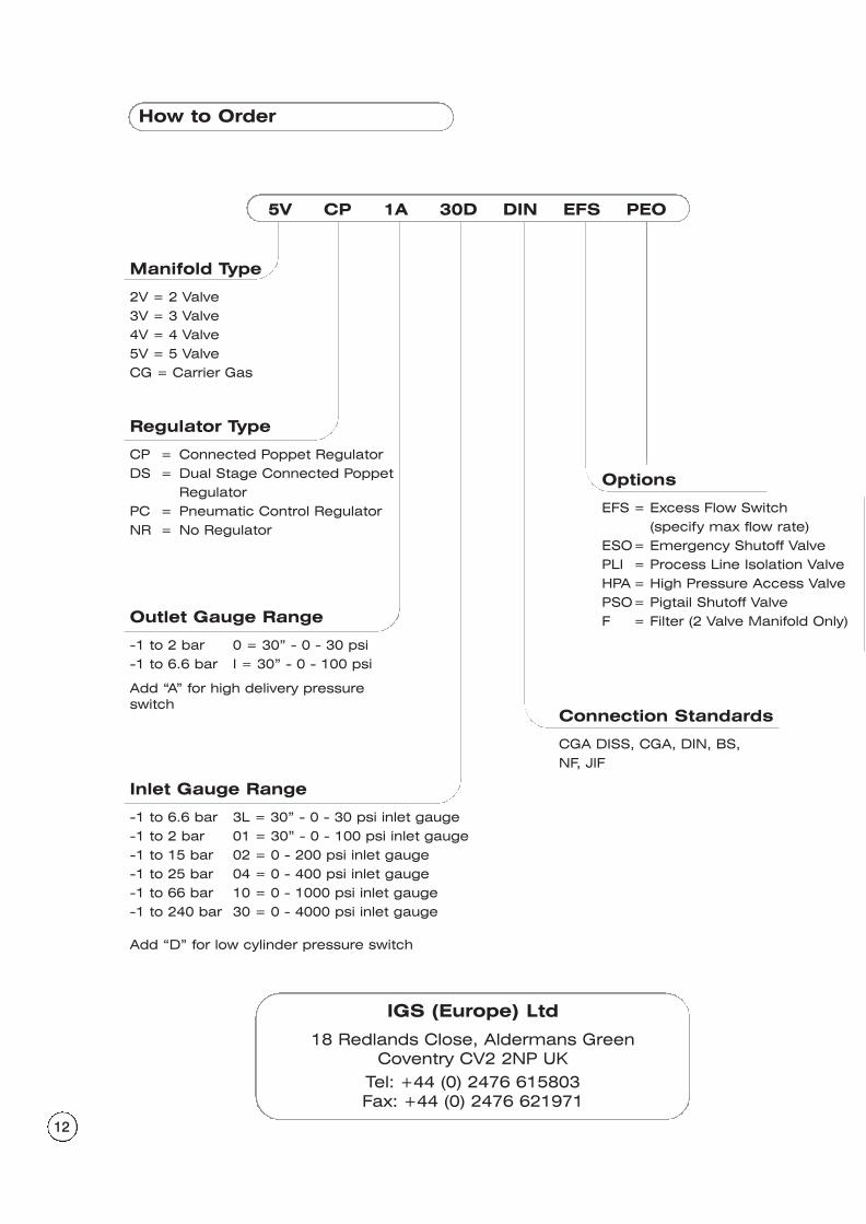
How to Order
Manifold Type
2V = 2 Valve3V = 3 Valve4V = 4 Valve5V = 5 ValveCG = Carrier Gas
Regulator Type
CP = Connected Poppet RegulatorDS = Dual Stage Connected Poppet
RegulatorPC = Pneumatic Control RegulatorNR = No Regulator
Connection Standards
CGA DISS, CGA, DIN, BS,NF, JIF
Outlet Gauge Range
-1 to 2 bar 0 = 30” - 0 - 30 psi -1 to 6.6 bar I = 30” - 0 - 100 psi
Add “A” for high delivery pressureswitch
Inlet Gauge Range
-1 to 6.6 bar 3L = 30” - 0 - 30 psi inlet gauge-1 to 2 bar 01 = 30” - 0 - 100 psi inlet gauge-1 to 15 bar 02 = 0 - 200 psi inlet gauge-1 to 25 bar 04 = 0 - 400 psi inlet gauge-1 to 66 bar 10 = 0 - 1000 psi inlet gauge-1 to 240 bar 30 = 0 - 4000 psi inlet gauge
Add “D” for low cylinder pressure switch
Options
EFS = Excess Flow Switch(specify max flow rate)
ESO= Emergency Shutoff ValvePLI = Process Line Isolation ValveHPA = High Pressure Access ValvePSO= Pigtail Shutoff ValveF = Filter (2 Valve Manifold Only)
IGS (Europe) Ltd
18 Redlands Close, Aldermans GreenCoventry CV2 2NP UK
Tel: +44 (0) 2476 615803Fax: +44 (0) 2476 621971
5V CP 1A 30D DIN EFS PEO


