W415-0341 / F / 11.21.05 GAS - DIRECT VENT MILLIVOLT SYSTEM INSTALLATION AND OPERATION INSTRUCTIONS FOR VENTED GAS FIREPLACE Installation and service must be performed by a qualified installer, service agency or the gas supplier. W ARNING: If the information in these instructions is not followed exactly, a fire or explosion may result causing property damage, personal injury or death. FOR YOUR SAFETY Do not store or use gasoline or other flammable vapours and liquids in the vicinity of this or any other appliance. WHA T TO DO IF Y OU SMELL GAS: • Do not try to light any appliance. • Do not touch any electrical switch. • Do not use any phone in your build ing. • Immediately call your gas supplier from a neighbour's phone. Follow the gas supplier's instructions. • If you cannot reach your gas supplier, call the fire department. NATURAL GAS MODEL GD33NR BGD33NR GD34NT BGD34NT PROPANE GAS MODEL GD33PR BGD33PR GD34PT BGD34PT CERTIFIED FOR CANADA AND UNITED STATES USING ANSI / CSA METHODS CERTIFIED UNDER CANADIAN AND AMERICAN NATIONAL STANDARDS, CSA 2.33, ANSI Z21.88 FOR VENTED GAS FIREPLACE HEATERS INSTALLER: THESE INSTRUCTIONS MUST BE CONVEYED TO AND REMAIN WITH THE HOMEOWNER. Wolf Steel Ltd., 24 Napoleon Rd., Barrie, ON L4M 4Y8 Canada • (705)721-1212 • fax(705)722-6031 www.napoleonfireplaces.com • [email protected]GAS-FIRED
Transcript
1
W415-0341 / F / 11.21.05
GAS - DIRECT VENT MILLIVOLT SYSTEMINSTALLATION AND OPERATION INSTRUCTIONS FOR
VENTED GAS FIREPLACE
Installation and service must be performed by a qualified installer, service agency
or the gas supplier.
WARNING: If the information in these instructions is not followed exactly, a fire or
explosion may result causing property damage, personal injury or death.
FOR YOUR SAFETY
Do not store or use gasoline or other flammable vapours and liquids in the vicinity of
this or any other appliance.
WHAT TO DO IF YOU SMELL GAS:
• Do not try to light any appliance.
• Do not touch any electrical switch.
• Do not use any phone in your build
ing.
• Immediately call your gas supplier
from a neighbour's phone. Follow
the gas supplier's instructions.
• If you cannot reach your gas
supplier, call the fire department.
NATURAL GAS MODEL GD33NR BGD33NRGD34NT BGD34NT
PROPANE GAS MODEL GD33PR BGD33PRGD34PT BGD34PT
CERTIFIED FOR CANADA AND UNITED STATES USING ANSI / CSA METHODS
CERTIFIED UNDER CANADIAN AND AMERICAN NATIONAL STANDARDS, CSA 2.33, ANSI Z21.88 FOR VENTED GAS FIREPLACE HEATERS
INSTALLER: THESE INSTRUCTIONS MUST BE CONVEYED TO AND REMAIN WITH THE HOMEOWNER.
Wolf Steel Ltd., 24 Napoleon Rd., Barrie, ON L4M 4Y8 Canada • (705)721-1212 • fax(705)722-6031www.napoleonfireplaces.com • [email protected]
GAS-FIRED
2
W415-0341 / F / 11.21.05
PG 2-5 INTRODUCTIONWarrantyGeneral InstructionsGeneral InformationCare of Glass & Plated PartsDimensions
NOTE: Changes, other than editorial, are denoted by a vertical line in the margin.
WARNING
• Do not burn wood or other materials in this fireplace.• Adults and especially children should be alerted to the hazards of high surface temperatures and should
stay away to avoid burns or clothing ignition. Supervise young children when they are in the same room asthe fireplace.
• Due to high temperatures, the fireplace should be located out of traffic and away from furniture and draper-ies.
• Clothing or other flammable material should not be placed on or near the fireplace.• Any safety screen or guard removed for servicing must be replaced prior to operating the fireplace.• It is imperative that the control compartments, burners and circulating blower and its passageway in the
fireplace and venting system are kept clean. The fireplace and its venting system should be inspectedbefore use and at least annually by a qualified service person. More frequent cleaning may be required dueto excessive lint from carpeting, bedding material, etc. The fireplace area must be kept clear and free fromcombustible materials, gasoline and other flammable vapours and liquids.
• Under no circumstances should this fireplace be modified.• This fireplace must not be connected to a chimney flue pipe serving a separate solid fuel burning appliance.• Do not use this fireplace if any part has been under water. Immediately call a qualified service technician to
inspect the fireplace and to replace any part of the control system and any gas control which has beenunder water.
• Do not operate the fireplace with the glass door removed, cracked or broken. Replacement of the glassshould be done by a licensed or qualified service person. Use only with a glass door certified with thefireplace.
• Do not strike or slam shut the fireplace glass door.• This fireplace uses and requires a fast acting thermocouple. Replace only with a fast acting thermocouple
supplied by Wolf Steel Ltd.
TABLE of CONTENTS
PLEASE RETAIN THIS MANUAL FOR FUTURE REFERENCE
3
W415-0341 / F / 11.21.05
NAPOLEON products are manufactured under the strict Standard of the world recognizedISO 9001 : 2000 Quality Assurance Certificate.
NAPOLEON products are designed with superior components and materials, assembled by trained craftsmen whotake great pride in their work. The burner and valve assembly are leak and test-fired at a quality test station. Thecomplete fireplace is again thoroughly inspected by a qualified technician before packaging to ensure that you, thecustomer, receives the quality product that you expect from NAPOLEON.
NAPOLEON GAS FIREPLACE PRESIDENT'S LIFETIME LIMITED WARRANTY
The following materials and workmanship in your new The following materials and workmanship in your new The following materials and workmanship in your new The following materials and workmanship in your new The following materials and workmanship in your new NAPOLEONNAPOLEONNAPOLEONNAPOLEONNAPOLEON gas fireplace are warranted against defects gas fireplace are warranted against defects gas fireplace are warranted against defects gas fireplace are warranted against defects gas fireplace are warranted against defectsfor as long as you own the fireplace. This covers: combustion chamber, heat exchanger, stainless steel burner,for as long as you own the fireplace. This covers: combustion chamber, heat exchanger, stainless steel burner,for as long as you own the fireplace. This covers: combustion chamber, heat exchanger, stainless steel burner,for as long as you own the fireplace. This covers: combustion chamber, heat exchanger, stainless steel burner,for as long as you own the fireplace. This covers: combustion chamber, heat exchanger, stainless steel burner,phazer™ logs and embers, ceramic glass (thermal breakage only), gold plated parts against tarnishing, porcelainizedphazer™ logs and embers, ceramic glass (thermal breakage only), gold plated parts against tarnishing, porcelainizedphazer™ logs and embers, ceramic glass (thermal breakage only), gold plated parts against tarnishing, porcelainizedphazer™ logs and embers, ceramic glass (thermal breakage only), gold plated parts against tarnishing, porcelainizedphazer™ logs and embers, ceramic glass (thermal breakage only), gold plated parts against tarnishing, porcelainizedenamelled components and aluminum extrusion trims.enamelled components and aluminum extrusion trims.enamelled components and aluminum extrusion trims.enamelled components and aluminum extrusion trims.enamelled components and aluminum extrusion trims.
Electrical (110V and millivolt) components and wearable parts such as blowers, gas valves, thermal switch,Electrical (110V and millivolt) components and wearable parts such as blowers, gas valves, thermal switch,Electrical (110V and millivolt) components and wearable parts such as blowers, gas valves, thermal switch,Electrical (110V and millivolt) components and wearable parts such as blowers, gas valves, thermal switch,Electrical (110V and millivolt) components and wearable parts such as blowers, gas valves, thermal switch,switches, wiring, remote controls, ignitor, gasketing, and pilot assembly are covered and switches, wiring, remote controls, ignitor, gasketing, and pilot assembly are covered and switches, wiring, remote controls, ignitor, gasketing, and pilot assembly are covered and switches, wiring, remote controls, ignitor, gasketing, and pilot assembly are covered and switches, wiring, remote controls, ignitor, gasketing, and pilot assembly are covered and NAPOLEONNAPOLEONNAPOLEONNAPOLEONNAPOLEON will providewill providewill providewill providewill providereplacement parts free of charge during the first year of the limited warranty.replacement parts free of charge during the first year of the limited warranty.replacement parts free of charge during the first year of the limited warranty.replacement parts free of charge during the first year of the limited warranty.replacement parts free of charge during the first year of the limited warranty.
Labour related to warranty repair is covered free of charge during the first year. Repair work, however, requiresLabour related to warranty repair is covered free of charge during the first year. Repair work, however, requiresLabour related to warranty repair is covered free of charge during the first year. Repair work, however, requiresLabour related to warranty repair is covered free of charge during the first year. Repair work, however, requiresLabour related to warranty repair is covered free of charge during the first year. Repair work, however, requiresthe prior approval of an authorized company official. Labour costs to the account of the prior approval of an authorized company official. Labour costs to the account of the prior approval of an authorized company official. Labour costs to the account of the prior approval of an authorized company official. Labour costs to the account of the prior approval of an authorized company official. Labour costs to the account of NAPOLEONNAPOLEONNAPOLEONNAPOLEONNAPOLEON are based on a are based on a are based on a are based on a are based on apredetermined rate schedule and any repair work must be done through an authorized predetermined rate schedule and any repair work must be done through an authorized predetermined rate schedule and any repair work must be done through an authorized predetermined rate schedule and any repair work must be done through an authorized predetermined rate schedule and any repair work must be done through an authorized NAPOLEONNAPOLEONNAPOLEONNAPOLEONNAPOLEON dealer. dealer. dealer. dealer. dealer.
CONDITIONS AND LIMITATIONS
NAPOLEON warrants its products against manufacturing defects to the original purchaser only -- i.e., the individual or legal entity (registered customer) whose name appears on thewarranty registration card filed with NAPOLEON -- provided that the purchase was made through an authorized NAPOLEON dealer and is subject to the following conditions and limitations:
This factory warranty is nontransferable and may not be extended whatsoever by any of our representatives.
The gas fireplace must be installed by a licenced, authorized service technician or contractor. Installation must be done in accordance with the installation instructions included with theproduct and all local and national building and fire codes.
This limited warranty does not cover damages caused by misuse, lack of maintenance, accident, alterations, abuse or neglect and parts installed from other manufacturers will nullify thiswarranty.
This limited warranty further does not cover any scratches, dents, corrosion or discolouring caused by excessive heat, abrasive and chemical cleaners nor chipping on porcelain enamelparts, mechanical breakage of PHAZER™ logs and embers, nor any venting components used in the installation of the fireplace.
NAPOLEON warrants its stainless steel burners against defects in workmanship and material for life, subject to the following conditions: During the first 10 years NAPOLEON will replaceor repair the defective parts at our option free of charge. From 10 years to life, NAPOLEON will provide replacement burners at 50% of the current retail price.
In the first year only, this warranty extends to the repair or replacement of warranted parts which are defective in material or workmanship provided that the product has been operated inaccordance with the operation instructions and under normal conditions.
After the first year, with respect to this President's Limited Lifetime Warranty, NAPOLEON may, at its discretion, fully discharge all obligations with respect to this warranty by refundingto the original warranted purchaser the wholesale price of any warranted but defective part(s).
After the first year, NAPOLEON will not be responsible for installation, labour or any other costs or expenses related to the reinstallation of a warranted part, and such expenses are notcovered by this warranty.
Notwithstanding any provisions contained in this President's Limited Lifetime Warranty, NAPOLEON’S responsibility under this warranty is defined as above and it shall not in any eventextend to any incidental, consequential or indirect damages.
This warranty defines the obligations and liability of NAPOLEON with respect to the NAPOLEON gas fireplace and any other warranties expressed or implied with respect to this product,its components or accessories are excluded.
NAPOLEON neither assumes, nor authorizes any third party to assume, on its behalf, any other liabilities with respect to the sale of this product. NAPOLEON will not be responsible for:over-firing, downdrafts, spillage caused by environmental conditions such as rooftops, buildings, nearby trees, hills, mountains, inadequate vents or ventilation, excessive venting configu-rations, insufficient makeup air, or negative air pressures which may or may not be caused by mechanical systems such as exhaust fans, furnaces, clothes dryers, etc.
Any damages to fireplace, combustion chamber, heat exchanger, brass trim or other component due to water, weather damage, long periods of dampness, condensation, damagingchemicals or cleaners will not be the responsibility of NAPOLEON.
The bill of sale or copy will be required together with a serial number and a model number when making any warranty claims from your authorized dealer. The warranty registration cardmust be returned within fourteen days to register the warranty.
NAPOLEON reserves the right to have its representative inspect any product or part thereof prior to honouring any warranty claim.
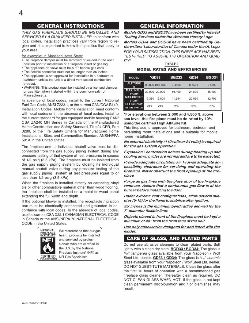
Models GD33 and BGD33 have been certified by Intertek
Testing Services under the Warnock Hersey Logo.
Models GD34 and BGD34 have been certified by Un-
derwriters' Laboratorities of Canada under the UL Logo.
FOR YOUR SATISFACTION, THIS FIREPLACE HAS BEENTEST-FIRED TO ASSURE ITS OPERATION AND QUAL-ITY!
MODEL RATES AND EFFICIENCIES
*For elevations between 2,000 and 4,500 ft. abovesea level, this fire place must be de-rated by 10%using the certified High Altitude Kit.This fireplace is approved for bathroom, bedroom andbed-sitting room installations and is suitable for mobilehome installation.No external electricity (110 volts or 24 volts) is required
for the gas system operation.
Expansion / contraction noises during heating up and
cooling down cycles are normal and are to be expected.
Provide adequate circulation air. Provide adequate ac-
cessibility clearance for servicing and operating the
fireplace. Never obstruct the front opening of the fire-
place.
Purge all gas lines with the glass door of the fireplace
removed. Assure that a continuous gas flow is at the
burner before installing the door.
Under extreme vent configurations, allow several min-
utes (5-15) for the flame to stabilize after ignition.
Six inches is the minimum bend radius allowed for the
7" diameter flexible liner.
Objects placed in front of the fireplace must be kept a
minimum of 48" from the front face of the unit.
Use only accessories designed for and listed with the
model.
Do not use abrasive cleaners to clean plated parts. Bufflightly with a clean dry cloth. BGD33 / BGD34: The glass is3/16" tempered glass available from your Napoleon / WolfSteel Ltd. dealer. GD33 / GD34: The glass is 3/16" ceramicglass available from your Napoleon / Wolf Steel Ltd. dealer.DO NOT SUBSTITUTE MATERIALS. Clean the glass afterthe first 10 hours of operation with a recommended gasfireplace glass cleaner. Thereafter clean as required. DONOT CLEAN GLASS WHEN HOT! If the glass is not keptclean permanent discolouration and / or blemishes mayresult.
THIS GAS FIREPLACE SHOULD BE INSTALLED ANDSERVICED BY A QUALIFIED INSTALLER to conform withlocal codes. Installation practices vary from region to re-gion and it is important to know the specifics that apply toyour area,
for example: in Massachusetts State:• The fireplace damper must be removed or welded in the open
position prior to installation of a fireplace insert or gas log.• The appliance off valve must be a “T” handle gas cock.• The flexible connector must not be longer than 36 inches.• The appliance is not approved for installation in a bedroom or
bathroom unless the unit is a direct vent sealed combustionproduct.
• WARNING: This product must be installed by a licensed plumberor gas fitter when installed within the commonwealth ofMassachusetts.
In absence of local codes, install to the current NationalFuel Gas Code, ANSI Z223.1, or the current CAN/CGA B149,Installation Codes. Mobile home installation must conformwith local codes or in the absence of local codes, install tothe current standard for gas equipped mobile housing CAN/CSA ZA240 MH Series in Canada or the ManufacturedHome Construction and Safety Standard, Title 24 CFR, Part3280, or the Fire Safety Criteria for Manufactured HomeInstallations, Sites, and Communities Standard ANSI/NFPA501A in the United States.
The fireplace and its individual shutoff valve must be dis-connected from the gas supply piping system during anypressure testing of that system at test pressures in excessof 1/2 psig (3.5 kPa). The fireplace must be isolated fromthe gas supply piping system by closing its individualmanual shutoff valve during any pressure testing of thegas supply piping system at test pressures equal to orless than 1/2 psig (3.5 kPa).When the fireplace is installed directly on carpeting, vinyltile or other combustible material other than wood flooring,the fireplace shall be installed on a metal or wood panelextending the full width and depth.If the optional blower is installed, the receptacle / junctionbox must be electrically connected and grounded in ac-cordance with local codes. In the absence of local codes,use the current CSA C22.1 CANADIAN ELECTRICAL CODEin Canada or the ANSI/NFPA 70 NATIONAL ELECTRICALCODE in the United States.
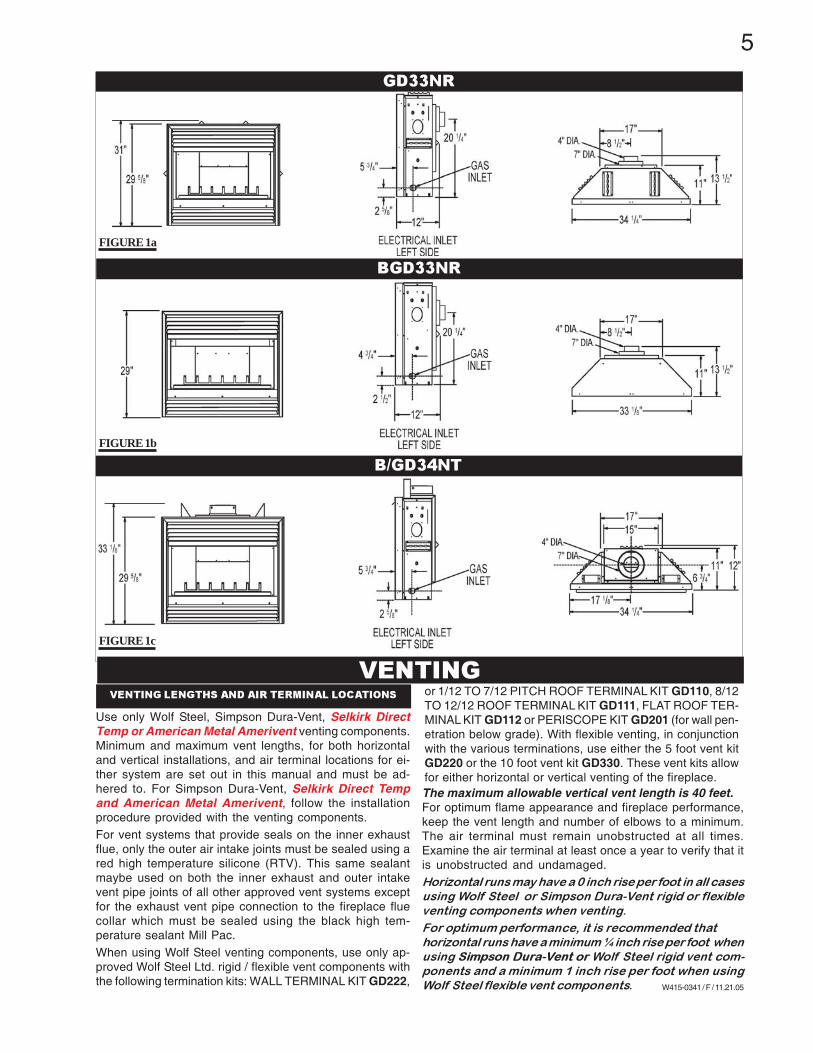
Use only Wolf Steel, Simpson Dura-Vent, Selkirk DirectTemp or American Metal Amerivent venting components.Minimum and maximum vent lengths, for both horizontaland vertical installations, and air terminal locations for ei-ther system are set out in this manual and must be ad-hered to. For Simpson Dura-Vent, Selkirk Direct Tempand American Metal Amerivent, follow the installationprocedure provided with the venting components.For vent systems that provide seals on the inner exhaustflue, only the outer air intake joints must be sealed using ared high temperature silicone (RTV). This same sealantmaybe used on both the inner exhaust and outer intakevent pipe joints of all other approved vent systems exceptfor the exhaust vent pipe connection to the fireplace fluecollar which must be sealed using the black high tem-perature sealant Mill Pac.When using Wolf Steel venting components, use only ap-proved Wolf Steel Ltd. rigid / flexible vent components withthe following termination kits: WALL TERMINAL KIT GD222,
VENTING LENGTHS AND AIR TERMINAL LOCATIONS
VENTING
The maximum allowable vertical vent length is 40 feet.For optimum flame appearance and fireplace performance,keep the vent length and number of elbows to a minimum.The air terminal must remain unobstructed at all times.Examine the air terminal at least once a year to verify that itis unobstructed and undamaged.Horizontal runs may have a 0 inch rise per foot in all cases
using Wolf Steel or Simpson Dura-Vent rigid or flexible
venting components when venting.
For optimum performance, it is recommended that
horizontal runs have a minimum ¼ inch rise per foot when
using Simpson Dura-Vent or Wolf Steel rigid vent com-
ponents and a minimum 1 inch rise per foot when using
Wolf Steel flexible vent components.
GD33NR
BGD33NR
B/GD34NT
FIGURE 1a
FIGURE 1b
FIGURE 1c
or 1/12 TO 7/12 PITCH ROOF TERMINAL KIT GD110, 8/12TO 12/12 ROOF TERMINAL KIT GD111, FLAT ROOF TER-MINAL KIT GD112 or PERISCOPE KIT GD201 (for wall pen-etration below grade). With flexible venting, in conjunctionwith the various terminations, use either the 5 foot vent kitGD220 or the 10 foot vent kit GD330. These vent kits allowfor either horizontal or vertical venting of the fireplace.
6
W415-0341 / F / 11.21.05
SEE HORIZONTAL TERMINATION
FIGURE 3a - b
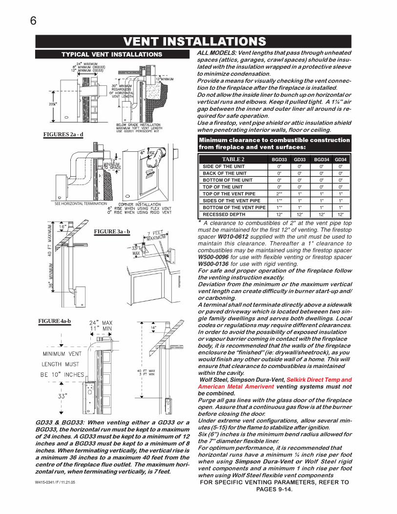
VENT INSTALLATIONS
* A clearance to combustibles of 2" at the vent pipe topmust be maintained for the first 12" of venting. The firestopspacer W010-0612 supplied with the unit must be used tomaintain this clearance. Thereafter a 1" clearance tocombustibles may be maintained using the firestop spacerW500-0096 for use with flexible venting or firestop spacerW500-0136 for use with rigid venting.For safe and proper operation of the fireplace follow
the venting instruction exactly.Deviation from the minimum or the maximum vertical
vent length can create difficulty in burner start-up and/or carboning.
A terminal shall not terminate directly above a sidewalkor paved driveway which is located betweeen two sin-
gle family dwellings and serves both dwellings. Localcodes or regulations may require different clearances.
In order to avoid the possibility of exposed insulationor vapour barrier coming in contact with the fireplace
body, it is recommended that the walls of the fireplaceenclosure be “finished” (ie: drywall/sheetrock), as you
would finish any other outside wall of a home. This willensure that clearance to combustibles is maintained
within the cavity.Wolf Steel, Simpson Dura-Vent, Selkirk Direct Temp andAmerican Metal Amerivent venting systems must notbe combined.Purge all gas lines with the glass door of the fireplaceopen. Assure that a continuous gas flow is at the burner
before closing the door.Under extreme vent configurations, allow several min-
utes (5-15) for the flame to stabilize after ignition.Six (6") inches is the minimum bend radius allowed for
the 7" diameter flexible liner.For optimum performance, it is recommended that
horizontal runs have a minimum ¼ inch rise per footwhen using Simpson Dura-Vent or Wolf Steel rigid
vent components and a minimum 1 inch rise per foot
when using Wolf Steel flexible vent components
FOR SPECIFIC VENTING PARAMETERS, REFER TOPAGES 9-14.
GD33 & BGD33: When venting either a GD33 or a
BGD33, the horizontal run must be kept to a maximum
of 24 inches. A GD33 must be kept to a minimum of 12
inches and a BGD33 must be kept to a minimum of 8
inches. When terminating vertically, the vertical rise is
a minimum 36 inches to a maximum 40 feet from the
centre of the fireplace flue outlet. The maximum hori-
zontal run, when terminating vertically, is 7 feet.
FIGURES 2a - d
FIGURE 4a-b
Minimum clearance to combustible constructionfrom fireplace and vent surfaces:
BGD33 GD33 BGD34 GD34
SIDE OF THE UNIT 0" 0" 0" 0"
BACK OF THE UNIT 0" 0" 0" 0"
BOTTOM OF THE UNIT 0" 0" 0" 0"
TOP OF THE UNIT 0" 0" 0" 0"
TOP OF THE VENT PIPE 2"* 1" 1" 1"
SIDES OF THE VENT PIPE 1"* 1" 1" 1"
BOTTOM OF THE VENT PIPE 1"* 1" 1" 1"
RECESSED DEPTH 12" 12" 12" 12"
TABLE 2
ALL MODELS: Vent lengths that pass through unheated
spaces (attics, garages, crawl spaces) should be insu-
lated with the insulation wrapped in a protective sleeve
to minimize condensation.
Provide a means for visually checking the vent connec-
tion to the fireplace after the fireplace is installed.
Do not allow the inside liner to bunch up on horizontal or
vertical runs and elbows. Keep it pulled tight. A 1¼" air
gap between the inner and outer liner all around is re-
quired for safe operation.
Use a firestop, vent pipe shield or attic insulation shield
when penetrating interior walls, floor or ceiling.
TYPICAL VENT INSTALLATIONS
7
W415-0341 / F / 11.21.05
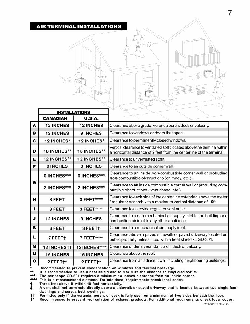
AIR TERMINAL INSTALLATIONS
***** Recommended to prevent condensation on windows and thermal breakage********** It is recommended to use a heat shield and to maximize the distance to vinyl clad soffits.*************** The periscope GD-201 requires a minimum 18 inches clearance from an inside corner.******************** This is a recommended distance. For additional requirements check local codes.††††† Three feet above if within 10 feet horizontally.‡‡‡‡‡ A vent shall not terminate directly above a sidewalk or paved driveway that is located between two single fami
dwellings and serves both dwellings.† †† †† †† †† † Permitted only if the veranda, porch, or deck is fully open on a minimum of two sides beneath the floor.†*†*†*†*†* Recommenced to prevent recirculation of exhaust products. For additional requirements check local codes.
A
B
C
D
E
F
G
H
I
J
K
L
M
N
O
12 INCHES
9 INCHES
12 INCHES*
18 INCHES**
12 INCHES**
0 INCHES
0 INCHES***
2 INCHES***
3 FEET****
3 FEET****
9 INCHES
3 FEET†
7 FEET****
12 INCHES****
16 INCHES
2 FEET†*
Clearance above grade, veranda porch, deck or balcony.
Clearance to windows or doors that open.
Clearance to permanently closed windows.
Vertical clearance to ventilated soffit located above the terminal withina horizontal distance of 2 feet from the centerline of the terminal.
Clearance to unventilated soffit.
Clearance to an outside corner wall.
Clearance to an inside non-combustible corner wall or protrudingnon-combustible obstructions (chimney, etc.).
Clearance to an inside combustible corner wall or protruding com-bustible obstructions ( vent chase, etc.).
Clearance to each side of the centerline extended above the meter/ regulator assembly to a maximum vertical distance of 15ft.
Clearance to a service regulator vent outlet.
Clearance to a non-mechanical air supply inlet to the building or acombustion air inlet to any other appliance.
Clearance to a mechanical air supply inlet.
Clearance above a paved sidewalk or paved driveway located onpublic property unless fitted with a heat shield kit GD-301.
Clearance under a veranda, porch, deck or balcony.
Clearance above the roof.
Clearance from an adjacent wall including neighbouring buildings.
CANADIAN U.S.A.
12 INCHES
12 INCHES
12 INCHES*
18 INCHES**
12 INCHES**
0 INCHES
0 INCHES***
2 INCHES***
3 FEET
3 FEET
12 INCHES
6 FEET
7 FEET‡
12 INCHES††
16 INCHES
2 FEET†*
INSTALLATIONS
8
W415-0341 / F / 11.21.05
ho
riz
on
tal
run
+ v
ert
i-
ca
l ris
e t
o
ma
xim
um
of
40
fe
et
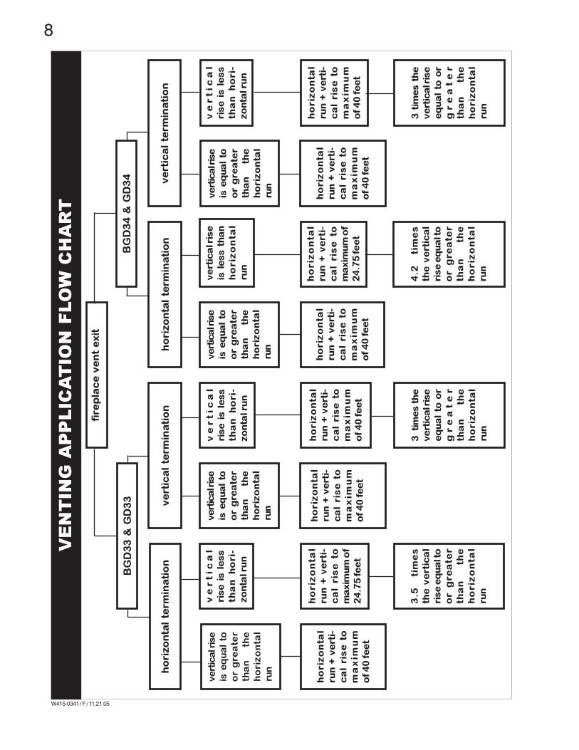
fire
pla
ce
ve
nt
ex
it
BG
D3
3 &
GD
33
BG
D3
4 &
GD
34
ho
riz
on
tal
term
ina
tio
nv
ert
ica
l te
rmin
ati
on
ve
rtic
al
term
ina
tio
n
ve
rtic
al r
ise
is e
qu
al
to
or
gre
ate
r
tha
n
the
ho
riz
on
tal
run
ve
rt
ic
al
ris
e i
s l
es
s
tha
n
ho
ri-
zo
nta
l ru
n
ho
riz
on
tal
run
+ v
ert
i-
ca
l ris
e t
o
ma
xim
um
of
40
fe
et
ho
riz
on
tal
run
+ v
ert
i-
ca
l ris
e to
ma
xim
um
of
24
.75
fe
et
3.5
ti
me
s
the
ve
rtic
al
ris
e e
qu
al t
o
or
gre
ate
r
tha
n
the
ho
riz
on
tal
run
ho
riz
on
tal
term
ina
tio
n
ve
rtic
al r
ise
is e
qu
al
to
or
gre
ate
r
tha
n
the
ho
riz
on
tal
run
ho
riz
on
tal
run
+ v
ert
i-
ca
l ris
e t
o
ma
xim
um
of
40
fe
et
ve
rtic
al r
ise
is e
qu
al
to
or
gre
ate
r
tha
n
the
ho
riz
on
tal
run
ho
riz
on
tal
run
+ v
ert
i-
ca
l ris
e t
o
ma
xim
um
of
40
fe
et
ve
rtic
al r
ise
is e
qu
al
to
or
gre
ate
r
tha
n
the
ho
riz
on
tal
run
ho
riz
on
tal
run
+ v
ert
i-
ca
l ris
e t
o
ma
xim
um
of
40
fe
et
ve
rt
ic
al
ris
e i
s l
es
s
tha
n
ho
ri-
zo
nta
l ru
n
3 ti
me
s t
he
ve
rtic
al r
ise
eq
ua
l to
or
gr
ea
te
r
tha
n
the
ho
riz
on
tal
run
ve
rtic
al r
ise
is l
es
s t
ha
n
ho
riz
on
tal
run
ho
riz
on
tal
run
+ v
ert
i-
ca
l ris
e to
ma
xim
um
of
24
.75
fe
et
4.2
ti
me
s
the
ve
rtic
al
ris
e e
qu
al t
o
or
gre
ate
r
tha
n
the
ho
riz
on
tal
run
ve
rt
ic
al
ris
e i
s l
es
s
tha
n
ho
ri-
zo
nta
l ru
n
ho
riz
on
tal
run
+ v
ert
i-
ca
l ris
e t
o
ma
xim
um
of
40
fe
et
3 t
ime
s t
he
ve
rtic
al r
ise
eq
ua
l to
or
gr
ea
te
r
tha
n
the
ho
riz
on
tal
run
VE
NT
IN
G A
PP
LIC
AT
IO
N F
LO
W C
HA
RT
9
W415-0341 / F / 11.21.05
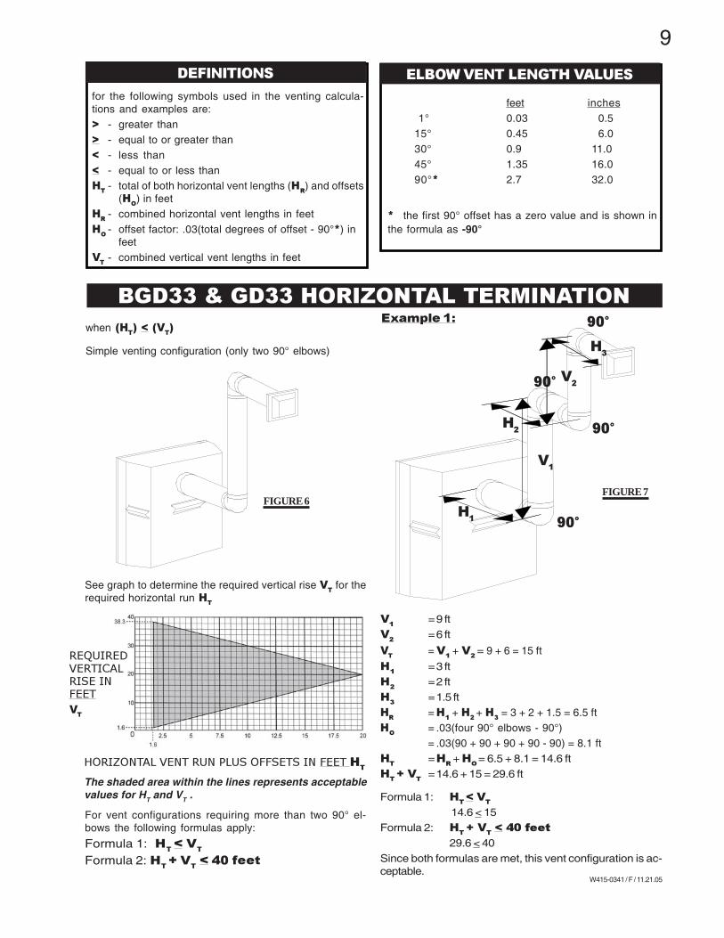
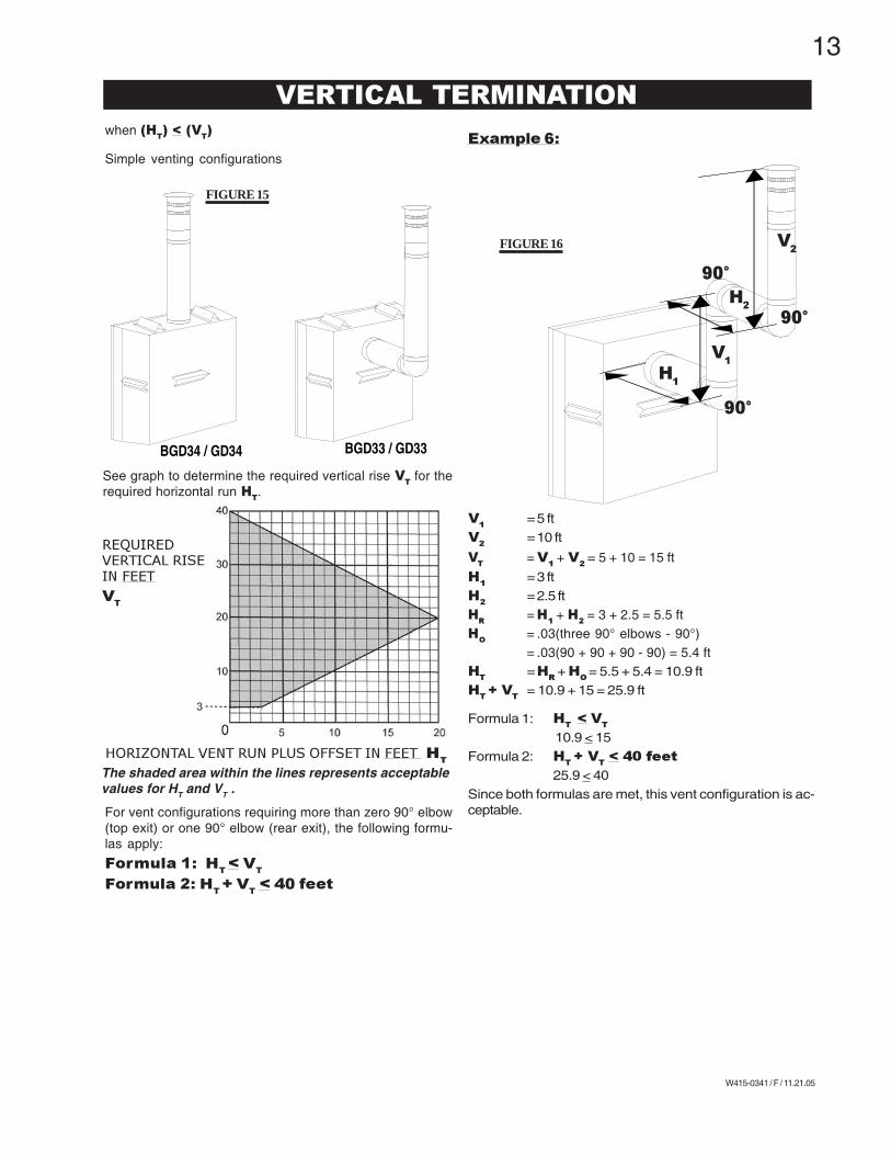
when (HT) < (V
T)
Simple venting configuration (only two 90° elbows)
for the following symbols used in the venting calcula-tions and examples are:> - greater than> - equal to or greater than< - less than< - equal to or less thanH
T- total of both horizontal vent lengths (H
R) and offsets
(HO) in feet
HR
- combined horizontal vent lengths in feetH
O- offset factor: .03(total degrees of offset - 90°*) in
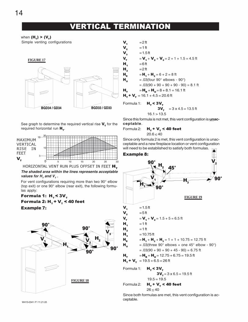
Since this formula is not met, this vent configuration is unac-ceptable.Formula 2: H
T + V
T < 40 feet
20.6 < 40Since only formula 2 is met, this vent configuration is unac-ceptable and a new fireplace location or vent configurationwill need to be established to satisfy both formulas.
26 < 40Since both formulas are met, this vent configuration is ac-ceptable.
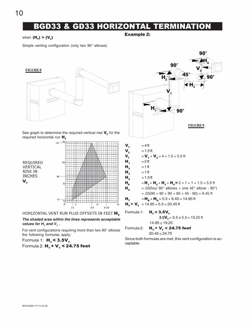
when (HT) > (V
T)
FIGURE 17
Simple venting configurations
VERTICAL TERMINATION
BGD34 / GD34 BGD33 / GD33
FIGURE 18
H1
H2
V3
V1
90°90°
90°
V2
90°
FIGURE 19
H2
H3
V1
V2
90°
45°
90°
H1
90°
15
W415-0341 / F / 11.21.05
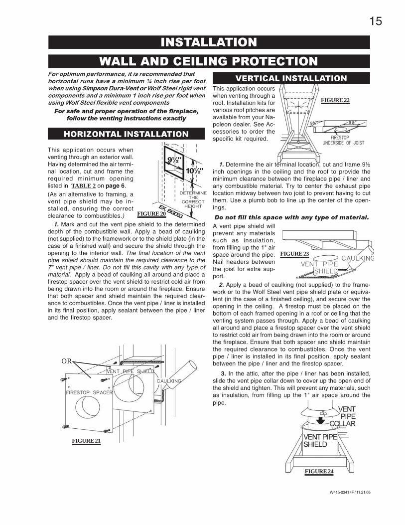
This application occurswhen venting through aroof. Installation kits forvarious roof pitches areavailable from your Na-poleon dealer. See Ac-cessories to order thespecific kit required.
1. Determine the air terminal location, cut and frame 9½inch openings in the ceiling and the roof to provide theminimum clearance between the fireplace pipe / liner andany combustible material. Try to center the exhaust pipelocation midway between two joist to prevent having to cutthem. Use a plumb bob to line up the center of the open-ings.
Do not fill this space with any type of material.
A vent pipe shield willprevent any materialssuch as insulation,from filling up the 1" airspace around the pipe.Nail headers betweenthe joist for extra sup-port.
2. Apply a bead of caulking (not supplied) to the frame-work or to the Wolf Steel vent pipe shield plate or equiva-lent (in the case of a finished ceiling), and secure over theopening in the ceiling. A firestop must be placed on thebottom of each framed opening in a roof or ceiling that theventing system passes through. Apply a bead of caulkingall around and place a firestop spacer over the vent shieldto restrict cold air from being drawn into the room or aroundthe fireplace. Ensure that both spacer and shield maintainthe required clearance to combustibles. Once the ventpipe / liner is installed in its final position, apply sealantbetween the pipe / liner and the firestop spacer.
3. In the attic, after the pipe / liner has been installed,slide the vent pipe collar down to cover up the open end ofthe shield and tighten. This will prevent any materials, suchas insulation, from filling up the 1" air space around thepipe.
For optimum performance, it is recommended that
horizontal runs have a minimum ¼ inch rise per foot
when using Simpson Dura-Vent or Wolf Steel rigid vent
components and a minimum 1 inch rise per foot when
using Wolf Steel flexible vent components
For safe and proper operation of the fireplace,
follow the venting instructions exactly
This application occurs whenventing through an exterior wall.Having determined the air termi-nal location, cut and frame therequired minimum openinglisted in TABLE 2 on page 6.(As an alternative to framing, avent pipe shield may be in-stalled, ensuring the correctclearance to combustibles.)
1. Mark and cut the vent pipe shield to the determineddepth of the combustible wall. Apply a bead of caulking(not supplied) to the framework or to the shield plate (in thecase of a finished wall) and secure the shield through theopening to the interior wall. The final location of the ventpipe shield should maintain the required clearance to the7" vent pipe / liner. Do not fill this cavity with any type ofmaterial. Apply a bead of caulking all around and place afirestop spacer over the vent shield to restrict cold air frombeing drawn into the room or around the fireplace. Ensurethat both spacer and shield maintain the required clear-ance to combustibles. Once the vent pipe / liner is installedin its final position, apply sealant between the pipe / linerand the firestop spacer.
FIGURE 23
FIGURE 22
FIGURE 21
OR
FIGURE 24
FIGURE 20
HORIZONTAL INSTALLATION
VERTICAL INSTALLATION
INSTALLATION
WALL AND CEILING PROTECTION
16
W415-0341 / F / 11.21.05
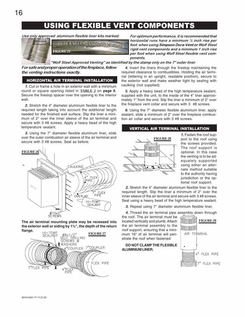
1. Fasten the roof sup-port to the roof usingthe screws provided.The roof support isoptional. In this casethe venting is to be ad-equately supportedusing either an alter-nate method suitableto the authority havingjurisdiction or the op-tional roof support.
2. Stretch the 4" diameter aluminium flexible liner to therequired length. Slip the liner a minimum of 2" over theinner sleeve of the air terminal and secure with 3 #8 screws.Seal using a heavy bead of the high temperature sealant.
3. Repeat using 7" diameter aluminium flexible liner.
4. Thread the air terminal pipe assembly down throughthe roof. The air terminal must belocated vertically and plumb. Attachthe air terminal assembly to theroof support, ensuring that a mini-mum 16" of air terminal will pen-etrate the roof when fastened.
DO NOT CLAMP THE FLEXIBLEALUMINIUM LINER.
Use only approved aluminum flexible liner kits marked:
"Wolf Steel Approved Venting" as identified by the stamp only on the 7” outer liner.
FIGURE 26
For safe and proper operation of the fireplace, follow
the venting instructions exactly.
1. Cut or frame a hole in an exterior wall with a minimumround or square opening listed in TABLE 2 on page 6.Secure the firestop spacer over the opening to the interiorwall.
2. Stretch the 4" diameter aluminum flexible liner to therequired length taking into account the additional lengthneeded for the finished wall surface. Slip the liner a mini-mum of 2" over the inner sleeve of the air terminal andsecure with 3 #8 screws. Apply a heavy bead of the hightemperature sealant.
3. Using the 7" diameter flexible aluminum liner, slideover the outer combustion air sleeve of the air terminal andsecure with 3 #8 screws. Seal as before.
The air terminal mounting plate may be recessed intothe exterior wall or siding by 1½", the depth of the returnflange.
4. Insert the liners through the firestop maintaining therequired clearance to combustibles. Holding the air termi-nal (lettering in an upright, readable position), secure tothe exterior wall and make weather tight by sealing withcaulking (not supplied).
5. Apply a heavy bead of the high temperature sealant,supplied with the unit, to the inside of the 4" liner approxi-mately 1" from the end. Slip the liner a minimum of 2" overthe fireplace vent collar and secure with 3 #8 screws.
6. Using the 7" diameter flexible aluminium liner, applysealant, slide a minimum of 2" over the fireplace combus-tion air collar and secure with 3 #8 screws.
FIGURE 27
USING FLEXIBLE VENT COMPONENTS
HORIZONTAL AIR TERMINAL INSTALLATION
VERTICAL AIR TERMINAL INSTALLATION
For optimum performance, it is recommended that
horizontal runs have a minimum ¼ inch rise per
foot when using Simpson Dura-Vent or Wolf Steel
rigid vent components and a minimum 1 inch rise
per foot when using Wolf Steel flexible vent com-
ponents.
FIGURE 25
FIGURE 28
FIGURE 29
17
W415-0341 / F / 11.21.05
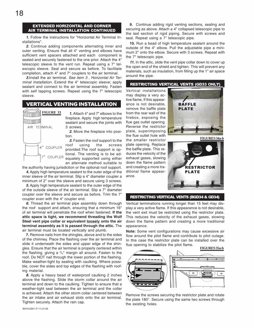
1. Move the fireplace into position. Measure the vent lengthrequired between terminal and fireplace taking into ac-count the additional length needed for the finished wallsurface and any 1¼" overlaps between venting compo-nents.
2. Apply high temperature sealant to the outer edge ofthe 4" inner collar of the fireplace. Attach the first vent com-ponent and secure using 3 self tapping screws. Repeatusing 7" piping.
3. Holding the air terminal (lettering in an upright, read-able position), insert into both vent pipes with a twistingmotion to ensure that both the terminal sleeves engageinto the vent pipes and the sealant. Secure the terminal tothe exterior wall and make weather tight by sealing withcaulking (not supplied).
The air terminal mounting plate may be recessed into
the exterior wall or siding by 1½", the depth of the return
flange.
A 45° corner installationcan have 0 inch risebetween the fireplacecombustion air collarand the air terminal. Inthis case, vent lengthsmust be kept to a maxi-mum of 24". For longervent lengths, a mini-mum vertical rise of 24"is required.
FIGURE 32
EXTENDED HORIZONTAL AND CORNER
AIR TERMINAL INSTALLATION
For safe and proper operation of the fire-
place, follow the venting instructions exactly.
For optimum performance, it is recommended that hori-
zontal runs have a minimum ¼ inch rise per foot when
using Wolf Steel or Simpson Duravent rigid vent com-
ponents.
The vent system must be supported approximately every 3feet for both vertical and horizontal runs. Use Wolf Steelvent spacers W615-0033 every 3 feet on either side of eachelbow to maintain the minimum 1¼" clearance betweenthe outer and inner vent pipes. Use Napoleon support ringassembly W010-0370 or equivalent noncombustible strap-ping to maintain the minimum clearance to combustiblesfor both vertical and horizontal runs.
FIGURE 31
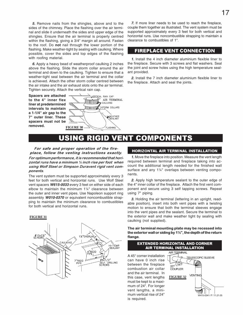
5. Remove nails from the shingles, above and to thesides of the chimney. Place the flashing over the air termi-nal and slide it underneath the sides and upper edge of theshingles. Ensure that the air terminal is properly centredwithin the flashing, giving a 3/4" margin all around. Fastento the roof. Do not nail through the lower portion of theflashing. Make weather-tight by sealing with caulking. Wherepossible, cover the sides and top edges of the flashingwith roofing material.
6. Apply a heavy bead of weatherproof caulking 2 inchesabove the flashing. Slide the storm collar around the airterminal and down to the caulking. Tighten to ensure that aweather-tight seal between the air terminal and the collaris achieved. Attach the other storm collar centred betweenthe air intake and the air exhaust slots onto the air terminal.Tighten securely. Attach the vertical rain cap.
Spacers are attachedto the 4" inner flexliner at predeterminedintervals to maintaina 1-1/4" air gap to the7" outer liner. Thesespacers must not beremoved.
7. If more liner needs to be used to reach the fireplace,couple them together as illustrated. The vent system must besupported approximately every 3 feet for both vertical andhorizontal runs. Use noncombustible strapping to maintain aclearance to combustibles of 1".
1. Install the 4 inch diameter aluminium flexible liner tothe fireplace. Secure with 3 screws and flat washers. Sealthe joint and screw holes using the high temperature seal-ant provided.
2. Install the 7 inch diameter aluminium flexible liner tothe fireplace. Attach and seal the joints.
FIREPLACE VENT CONNECTION
USING RIGID VENT COMPONENTS
HORIZONTAL AIR TERMINAL INSTALLATION
FIGURE 30
18
W415-0341 / F / 11.21.05
1. Follow the instructions for "Horizontal Air Terminal In-stallations".
2. Continue adding components alternating inner andouter venting. Ensure that all 4" venting and elbows havesufficient vent spacers attached and each component issealed and securely fastened to the one prior. Attach the 4"telescopic sleeve to the vent run. Repeat using a 7" tel-escopic sleeve. Seal and secure as before. To facilitatecompletion, attach 4" and 7" couplers to the air terminal.
3.Install the air terminal. See item 3 , Horizontal Air Ter-minal Installation. Extend the 4" telescopic sleeve; applysealant and connect to the air terminal assembly. Fastenwith self tapping screws. Repeat using the 7" telescopicsleeve.
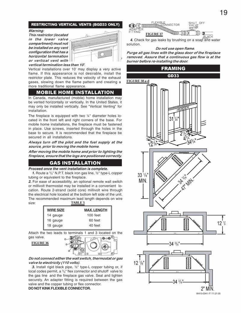
1. Attach 4" and 7" elbows to thefireplace. Apply high temperaturesealant and secure the joints with3 screws.
2. Move the fireplace into posi-tion.
3. Fasten the roof support to theroof using the screwsprovided.The roof support is op-tional. The venting is to be ad-equately supported using eitheran alternate method suitable to
the authority having jurisdiction or the optional roof support.4. Apply high temperature sealant to the outer edge of the
inner sleeve of the air terminal. Slip a 4" diameter coupler aminimum of 2" over the sleeve and secure using 3 screws.
5. Apply high temperature sealant to the outer edge of theof the outside sleeve of the air terminal. Slip a 7" diametercoupler over the sleeve and secure as before. Trim the 7"coupler even with the 4" coupler end.
6. Thread the air terminal pipe assembly down throughthe roof support and attach, ensuring that a minimum 16"of air terminal will penetrate the roof when fastened. If theattic space is tight, we recommend threading the WolfSteel vent pipe collar or equivalent loosely onto the airterminal assembly as it is passed through the attic. Theair terminal must be located vertically and plumb.
7. Remove nails from the shingles, above and to the sidesof the chimney. Place the flashing over the air terminal andslide it underneath the sides and upper edge of the shin-gles. Ensure that the air terminal is properly centered withinthe flashing, giving a 3/4" margin all around. Fasten to theroof. Do NOT nail through the lower portion of the flashing.Make weather-tight by sealing with caulking. Where possi-ble, cover the sides and top edges of the flashing with roof-ing material.
8. Apply a heavy bead of waterproof caulking 2 inchesabove the flashing. Slide the storm collar around the airterminal and down to the caulking. Tighten to ensure that aweather-tight seal between the air terminal and the collaris achieved. Attach the other storm collar centered betweenthe air intake and air exhaust slots onto the air terminal.Tighten securely. Attach the rain cap.
FIGURES 34a-b
Vertical installationsmay display a very ac-tive flame. If this appear-ance is not desirable,remove the baffle platefrom the rear wall of thefirebox, exposing theflue gas outlet opening.Reverse the restrictorplate, superimposingthe flue outlet hole withthe smaller restrictorplate opening. Replacethe baffle plate. This re-duces the velocity of theexhaust gases, slowingdown the flame patternand creating a more tra-ditional flame appear-ance.
9. Continue adding rigid venting sections, sealing andsecuring as above. Attach a 4" collapsed telescopic pipe tothe last section of rigid piping. Secure with screws andseal. Repeat using a 7" telescopic pipe.
10. Run a bead of high temperature sealant around theoutside of the 4" elbow. Pull the adjustable pipe a mini-mum 2" onto the elbow. Secure with 3 screws. Repeat withthe 7" telescopic pipe.
11. In the attic, slide the vent pipe collar down to cover upthe open end of the shield and tighten. This will prevent anymaterials, such as insulation, from filling up the 1" air spacearound the pipe.
VERTICAL VENTING INSTALLATION
RESTRICTING VERTICAL VENTS (GD33 ONLY)
Vertical terminations running longer than 15 feet may dis-play a very active flame. If this appearance is not desirable,the vent exit must be restricted using the restrictor plate.This reduces the velocity of the exhaust gases, slowingdown the flame pattern and creating a more traditionalappearance.
EXTENDED HORIZONTAL AND CORNERAIR TERMINAL INSTALLATION CONTINUED
FIGURES 35a-b
RESTRICTING VERTICAL VENTS (BGD34 & GD34)
Remove the screws securing the restrictor plate and rotatethe plate 180°. Secure using the same two screws throughthe existing holes.
Note: Some vent configurations may cause excessive airflow around the pilot flame and contribute to pilot outage.In this case the restrictor plate can be installed over theflue opening to stabilize the pilot flame.
FIGURE 33
BAFFLE
PLATE
RESTRICTOR
PLATE
19
W415-0341 / F / 11.21.05
4. Check for gas leaks by brushing on a soap and watersolution.
Do not use open flame.
Purge all gas lines with the glass door of the fireplace
removed. Assure that a continuous gas flow is at the
burner before re-installing the door.
Proceed once the vent installation is complete.1. Route a 3/8" N.P.T. black iron gas line, ½" type-L copper
tubing or equivalent to the fireplace.2. For ease of accessibility, an optional remote wall switchor millivolt thermostat may be installed in a convenient lo-cation. Route 2-strand (solid core) millivolt wire throughthe electrical hole located at the bottom left side of the unit.The recommended maximum lead length depends on wiresize:
Attach the two leads to terminals 1 and 3 located on thegas valve.
Do not connect either the wall switch, thermostat or gas
valve to electricity (110 volts).
3. Install rigid black pipe, ½" type-L copper tubing or, iflocal codes permit, a 3/8" flex connector and shutoff valve tothe gas line and the fireplace gas valve. Seal and tightensecurely. An adapter fitting is required between the gasvalve and the copper tubing or flex connector.DO NOT KINK FLEXIBLE CONNECTOR.
In Canada, manufactured (mobile) home installation maybe vented horizontally or vertically. In the United States, itmay only be installed vertically. See "Vertical Venting" forinstallation.The fireplace is equipped with two ¼" diameter holes lo-cated in the front left and right corners of the base. Formobile home installations, the fireplace must be fastenedin place. Use screws, inserted through the holes in thebase to secure. It is recommended that the fireplace besecured in all installations.Always turn off the pilot and the fuel supply at the
source, prior to moving the mobile home.
After moving the mobile home and prior to lighting the
fireplace, ensure that the logs are positioned correctly.
GD33
TABLE 3
FIGURE 36
FIGURE 38 a-d
RESTRICTING VERTICAL VENTS (BGD33 ONLY)
Warning:
This restrictor (located
in the lower valve
compartment) must not
be installed on any vent
configuration that has a
horizontal termination
or vertical vent with
vertical termination less than 10'.
Vertical installations over 10' may display a very activeflame. If this appearance is not desirable, install therestrictor plate. This reduces the velocity of the exhaustgases, slowing down the flame pattern and creating amore traditional flame appearance.
20
W415-0341 / F / 11.21.05
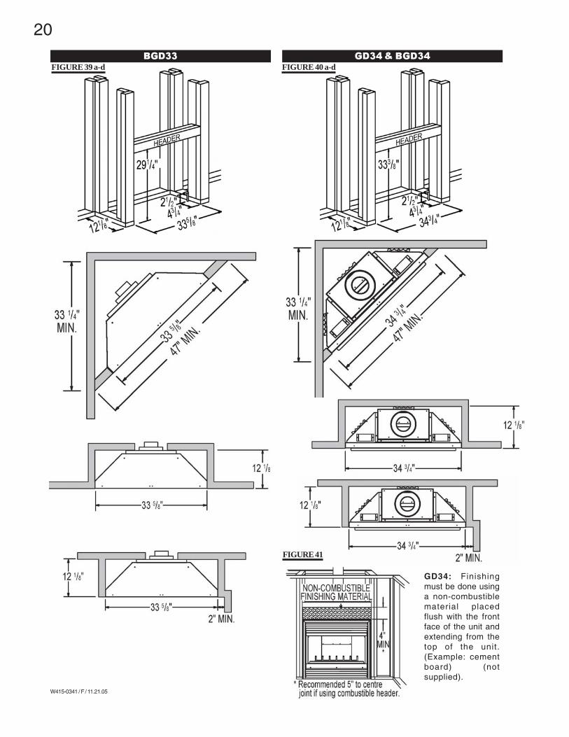
BGD33 GD34 & BGD34
FIGURE 39 a-d FIGURE 40 a-d
GD34: Finishingmust be done usinga non-combustiblematerial placedflush with the frontface of the unit andextending from thetop of the unit.(Example: cementboard) (notsupplied).
FIGURE 41
21
W415-0341 / F / 11.21.05
NAILING TAB
FIGURE 42
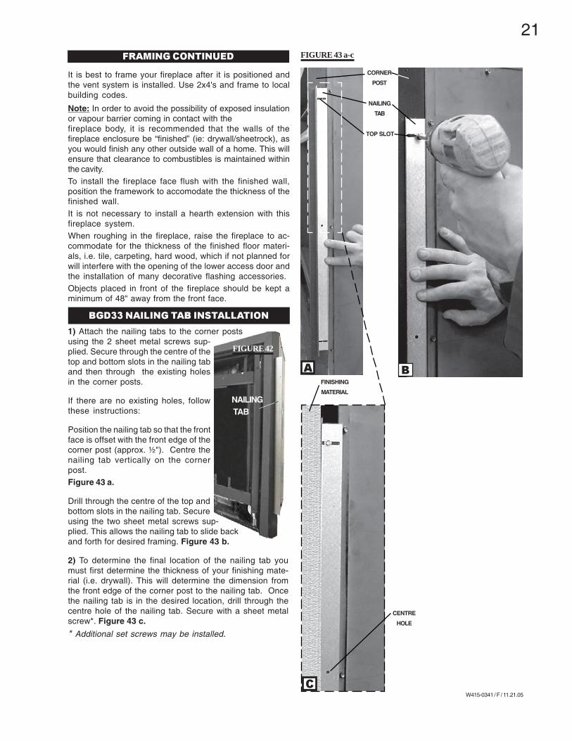
1) Attach the nailing tabs to the corner postsusing the 2 sheet metal screws sup-plied. Secure through the centre of thetop and bottom slots in the nailing taband then through the existing holesin the corner posts.
If there are no existing holes, followthese instructions:
Position the nailing tab so that the frontface is offset with the front edge of thecorner post (approx. ½"). Centre thenailing tab vertically on the cornerpost.Figure 43 a.
Drill through the centre of the top andbottom slots in the nailing tab. Secureusing the two sheet metal screws sup-plied. This allows the nailing tab to slide backand forth for desired framing. Figure 43 b.
2) To determine the final location of the nailing tab youmust first determine the thickness of your finishing mate-rial (i.e. drywall). This will determine the dimension fromthe front edge of the corner post to the nailing tab. Oncethe nailing tab is in the desired location, drill through thecentre hole of the nailing tab. Secure with a sheet metalscrew*. Figure 43 c.
* Additional set screws may be installed.
TOP SLOT
FINISHING
MATERIAL
CORNER
POST
NAILING
TAB
A B
C
CENTRE
HOLE
BGD33 NAILING TAB INSTALLATION
It is best to frame your fireplace after it is positioned andthe vent system is installed. Use 2x4's and frame to localbuilding codes.
Note: In order to avoid the possibility of exposed insulationor vapour barrier coming in contact with thefireplace body, it is recommended that the walls of thefireplace enclosure be “finished” (ie: drywall/sheetrock), asyou would finish any other outside wall of a home. This willensure that clearance to combustibles is maintained withinthe cavity.To install the fireplace face flush with the finished wall,position the framework to accomodate the thickness of thefinished wall.It is not necessary to install a hearth extension with thisfireplace system.When roughing in the fireplace, raise the fireplace to ac-commodate for the thickness of the finished floor materi-als, i.e. tile, carpeting, hard wood, which if not planned forwill interfere with the opening of the lower access door andthe installation of many decorative flashing accessories.Objects placed in front of the fireplace should be kept aminimum of 48" away from the front face.
FRAMING CONTINUED FIGURE 43 a-c
22
W415-0341 / F / 11.21.05
Mantle clearance can vary according to the mantle depth.Use the graph to help evaluate the clearance needed.Combustible materials must be installed flush with thefront of the fireplace but must not cover any of the blackface-area of the fireplace. Non-combustible material (brick,stone or ceramic tile) may protrude past the face of thefireplace.
GD33NR
BGD33NR
BGD34 & GD34
MANTLE CLEARANCES & ENCLOSURES
FIGURE 44a&b
FIGURE 46
FIGURE 47
FIGURE 45a&b
23
W415-0341 / F / 11.21.05
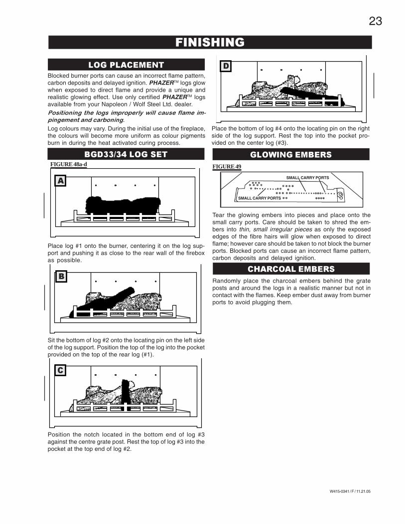
Blocked burner ports can cause an incorrect flame pattern,carbon deposits and delayed ignition. PHAZERTM logs glowwhen exposed to direct flame and provide a unique andrealistic glowing effect. Use only certified PHAZERTM logsavailable from your Napoleon / Wolf Steel Ltd. dealer.Positioning the logs improperly will cause flame im-
pingement and carboning.
Log colours may vary. During the initial use of the fireplace,the colours will become more uniform as colour pigmentsburn in during the heat activated curing process.
FINISHING
LOG PLACEMENT
BGD33/34 LOG SET GLOWING EMBERS
CHARCOAL EMBERS
Place log #1 onto the burner, centering it on the log sup-port and pushing it as close to the rear wall of the fireboxas possible.
Sit the bottom of log #2 onto the locating pin on the left sideof the log support. Position the top of the log into the pocketprovided on the top of the rear log (#1).
Position the notch located in the bottom end of log #3against the centre grate post. Rest the top of log #3 into thepocket at the top end of log #2.
Tear the glowing embers into pieces and place onto thesmall carry ports. Care should be taken to shred the em-bers into thin, small irregular pieces as only the exposededges of the fibre hairs will glow when exposed to directflame; however care should be taken to not block the burnerports. Blocked ports can cause an incorrect flame pattern,carbon deposits and delayed ignition.
Randomly place the charcoal embers behind the grateposts and around the logs in a realistic manner but not incontact with the flames. Keep ember dust away from burnerports to avoid plugging them.
A
FIGURE 48a-d
B
C
D
SMALL CARRY PORTS
SMALL CARRY PORTS
FIGURE 49
Place the bottom of log #4 onto the locating pin on the rightside of the log support. Rest the top into the pocket pro-vided on the center log (#3).
24
W415-0341 / F / 11.21.05
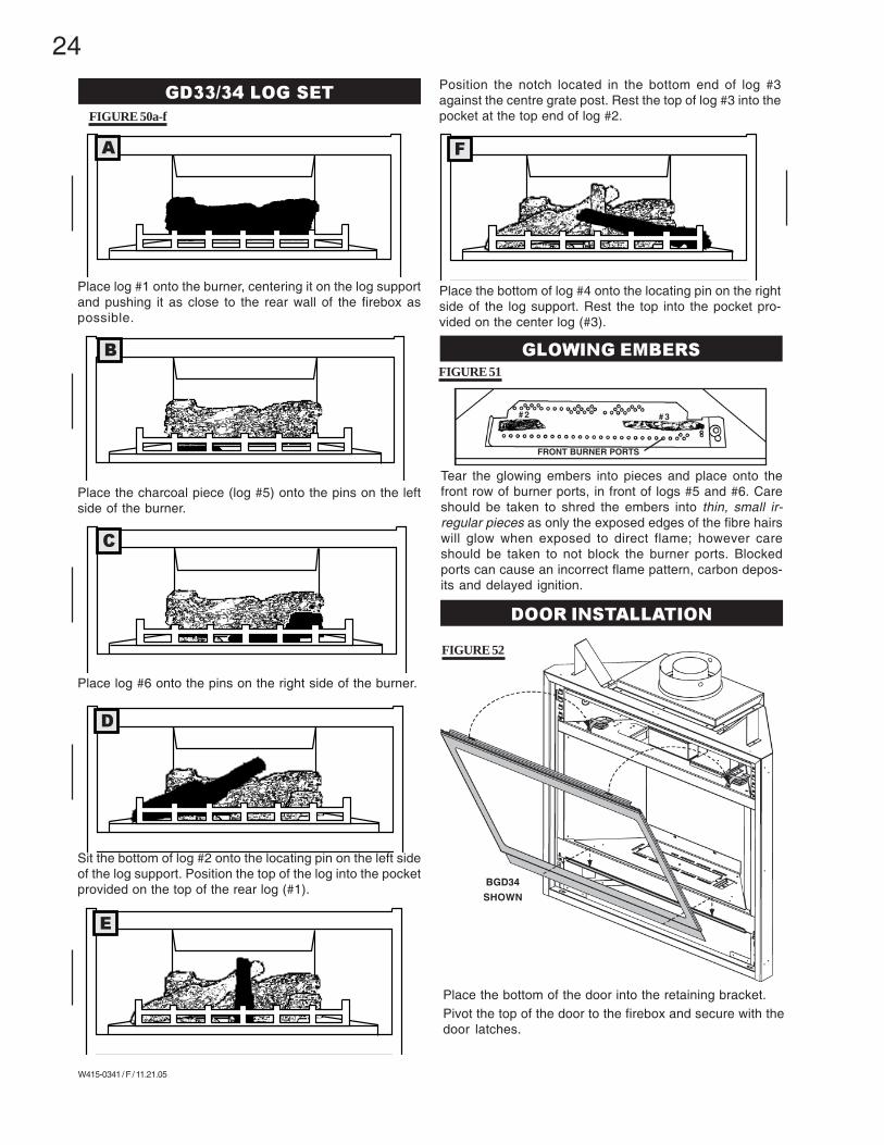
Place log #1 onto the burner, centering it on the log supportand pushing it as close to the rear wall of the firebox aspossible.
Place the charcoal piece (log #5) onto the pins on the leftside of the burner.
Place log #6 onto the pins on the right side of the burner.
Sit the bottom of log #2 onto the locating pin on the left sideof the log support. Position the top of the log into the pocketprovided on the top of the rear log (#1).
GD33/34 LOG SET
A
FIGURE 50a-f
B
C
D
E
F
GLOWING EMBERS
FRONT BURNER PORTS
# 3# 2
FIGURE 51
Position the notch located in the bottom end of log #3against the centre grate post. Rest the top of log #3 into thepocket at the top end of log #2.
Place the bottom of log #4 onto the locating pin on the rightside of the log support. Rest the top into the pocket pro-vided on the center log (#3).
Tear the glowing embers into pieces and place onto thefront row of burner ports, in front of logs #5 and #6. Careshould be taken to shred the embers into thin, small ir-regular pieces as only the exposed edges of the fibre hairswill glow when exposed to direct flame; however careshould be taken to not block the burner ports. Blockedports can cause an incorrect flame pattern, carbon depos-its and delayed ignition.
DOOR INSTALLATION
BGD34
SHOWN
Place the bottom of the door into the retaining bracket.Pivot the top of the door to the firebox and secure with thedoor latches.
FIGURE 52
25
W415-0341 / F / 11.21.05
GDL153 LOUVRE INSTALLATION
L334 LOUVRE INSTALLATION
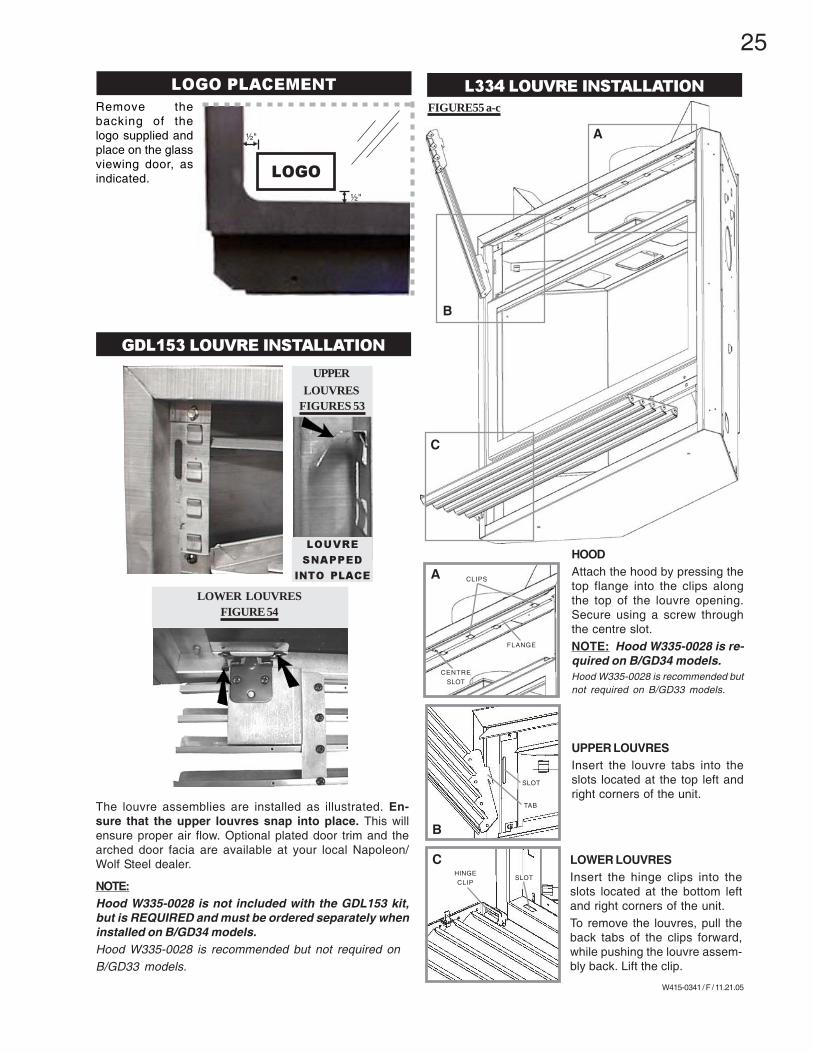
The louvre assemblies are installed as illustrated. En-sure that the upper louvres snap into place. This willensure proper air flow. Optional plated door trim and thearched door facia are available at your local Napoleon/Wolf Steel dealer.
NOTE:Hood W335-0028 is not included with the GDL153 kit,but is REQUIRED and must be ordered separately wheninstalled on B/GD34 models.Hood W335-0028 is recommended but not required onB/GD33 models.
FIGURE55 a-c
HOODAttach the hood by pressing thetop flange into the clips alongthe top of the louvre opening.Secure using a screw throughthe centre slot.NOTE: Hood W335-0028 is re-quired on B/GD34 models.Hood W335-0028 is recommended butnot required on B/GD33 models.
LOWER LOUVRESInsert the hinge clips into theslots located at the bottom leftand right corners of the unit.To remove the louvres, pull theback tabs of the clips forward,while pushing the louvre assem-bly back. Lift the clip.
UPPER LOUVRESInsert the louvre tabs into theslots located at the top left andright corners of the unit.
A
C
B
CHINGECLIP
SLOT
LOWER LOUVRESFIGURE 54
UPPERLOUVRES
FIGURES 53
LOUVRE
SNAPPED
INTO PLACE
SLOT
TAB
B
A CLIPS
CENTRESLOT
FLANGE
Remove thebacking of thelogo supplied andplace on the glassviewing door, asindicated.
LOGO PLACEMENT
LOGO
½"
½"
26
W415-0341 / F / 11.21.05
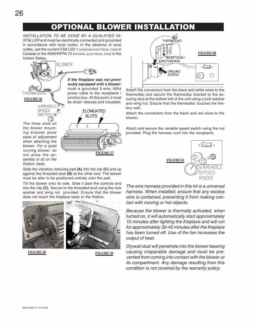
INSTALLATION TO BE DONE BY A QUALIFIED IN-STALLER and must be electrically connected and groundedin accordance with local codes. In the absence of localcodes, use the current CSA C22.1 CANADIAN ELECTRICAL CODE inCanada or the ANSI/NFPA 70 NATIONAL ELECTRICAL CODE in theUnited States.
If the fireplace was not previ-ously equipped with a blower:route a grounded 2-wire, 60hzpower cable to the receptacle /junction box. At this point, it mustbe strain relieved and insulated.
The three slots onthe blower mount-ing bracket allowease of adjustmentwhen attaching theblower. For a quietrunning blower, donot allow the as-sembly to sit on thefirebox base.Slide the vibration reducing pad (A) into the clip (C) and upagainst the threaded stud (B) at the other end. The blowermust be able to be positioned entirely onto the pad.Tilt the blower onto its side. Slide it past the controls andinto the clip (C). Secure to the threaded stud using the lockwasher and wing nut provided. Ensure that the blowerdoes not touch the fireplace base or the firebox.
Attach the connectors from the black and white wires to thethermodisc and secure the thermodisc bracket to the se-curing stud at the bottom left of the unit using a lock washerand wing nut. Ensure that the thermodisc touches the fire-box wall.Attach the connectors from the black and red wires to theblower.
Attach and secure the variable speed switch using the nutprovided. Plug the harness cord into the receptacle.
The wire harness provided in this kit is a universalharness. When installed, ensure that any excesswire is contained, preventing it from making con-tact with moving or hot objects.
Because the blower is thermally activated, whenturned on, it will automatically start approximately10 minutes after lighting the fireplace and will runfor approximately 30-45 minutes after the fireplacehas been turned off. Use of the fan increases theoutput of heat.
Drywall dust will penetrate into the blower bearingcausing irreparable damage and must be pre-vented from coming into contact with the blower orits compartment. Any damage resulting from thiscondition is not covered by the warranty policy.
FIGURE 57
FIGURE 56
FIGURE 61
FIGURE 60
FIGURE 59FIGURE 58
A
B
C
OPTIONAL BLOWER INSTALLATION
27
W415-0341 / F / 11.21.05
L
ON/OFFKNOB
FF
O
P
I
NO
L
O
T
IHPILOT
O
PILOT
ADJUSTMENTKNOB
FLAME
After extended periods of non-operation such as fol-
lowing a vacation or a warm weather season, the fire-
place may emit a slight odour for a few hours. This is
caused by dust particles in the heat exchanger burning
off. In both cases, open a window to sufficiently venti-
late the room.
Purge all gas lines with the glass door of the fireplace
removed. Assure that a continuous gas flow is at the
burner before installing the door.
When lit for the first time, the fireplace will emit a slight
odour for a few hours. This is a normal temporary con-
dition caused by the curing of the logs and the "burn-
in" of internal paints and lubricants used in the manu-
facturing process and will not occur again.
• Turn off all gas to the fireplace.• Open windows.• Do not try to light any appliance.• Do not touch any electric switch; do not use any phonein your building.• Immediately call your gas supplier from a neighbour'sphone. Follow the gas supplier's instructions.• If you cannot reach your gas supplier, call the fire de-partment.
GAS KNOB
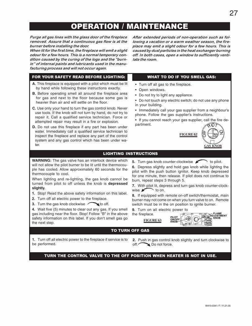
A. This fireplace is equipped with a pilot which must be litby hand while following these instructions exactly.
B. Before operating smell all around the fireplace areafor gas and next to the floor because some gas isheavier than air and will settle on the floor.
C. Use only your hand to turn the gas control knob. Neveruse tools. If the knob will not turn by hand, do not try torepair it. Call a qualified service technician. Force orattempted repair may result in a fire or explosion.
D. Do not use this fireplace if any part has been underwater. Immediately call a qualified service technician toinspect the fireplace and replace any part of the controlsystem and any gas control which has been under wa-ter.
WARNING: The gas valve has an interlock device whichwill not allow the pilot burner to be lit until the thermocou-ple has cooled. Allow approximately 60 seconds for thethermocouple to cool.When lighting and re-lighting, the gas knob cannot beturned from pilot to off unless the knob is depressedslightly.1. Stop! Read the above safety information on this label.2. Turn off all electric power to the fireplace.3. Turn the gas knob clockwise to off.4. Wait five (5) minutes to clear out any gas. If you smellgas including near the floor. Stop! Follow "B" in the abovesafety information on this label. If you don't smell gas gothe next step.
5. Turn gas knob counter-clockwise to pilot.6. Depress slightly and hold gas knob while lighting thepilot with the push button ignitor. Keep knob depressedfor one minute, then release. If pilot does not continue toburn, repeat steps 3 through 5.7. With pilot lit, depress and turn gas knob counter-clock-wise to on.8. If equipped with remote on-off switch/thermostat, mainburner may not come on when you turn valve to on. Remoteswitch must be in the on position to ignite burner.9. Turn on all electric power tothe fireplace.
1. Turn off all electric power to the fireplace if service is tobe performed.
2. Push in gas control knob slightly and turn clockwise tooff. Do not force.
OPERATION / MAINTENANCE
FOR YOUR SAFETY READ BEFORE LIGHTING: WHAT TO DO IF YOU SMELL GAS:
LIGHTING INSTRUCTIONS
TO TURN OFF GAS
TURN THE CONTROL VALVE TO THE OFF POSITION WHEN HEATER IS NOT IN USE.
FIGURE 62
FIGURE 63
28
W415-0341 / F / 11.21.05
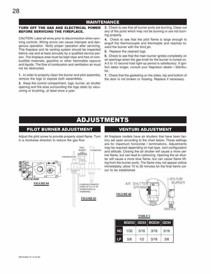
All fireplace models have air shutters that have been fac-tory set open according to the chart below. These settingsare for maximum horizontal / terminations. Adjustmentsmay be required depending on fuel type, vent configurationand altitude. Closing the air shutter will cause a more yel-low flame, but can lead to carboning. Opening the air shut-ter will cause a more blue flame, but can cause flame lift-ing from the burner ports. The flame may not appear yellowimmediately; allow 15 to 30 minutes for the final flame col-our to be established.
FIGURE 65
FIGURE 64
FIGURE 66
TURN OFF THE GAS AND ELECTRICAL POWERBEFORE SERVICING THE FIREPLACE.
CAUTION: Label all wires prior to disconnection when serv-icing controls. Wiring errors can cause improper and dan-gerous operation. Verify proper operation after servicing.This fireplace and its venting system should be inspectedbefore use and at least annually by a qualified service per-son. The fireplace area must be kept clear and free of com-bustible materials, gasoline or other flammable vapoursand liquids. The flow of combustion and ventilation air mustnot be obstructed.
1. In order to properly clean the burner and pilot assembly,remove the logs to expose both assemblies.2. Keep the control compartment, logs, burner, air shutteropening and the area surrounding the logs clean by vacu-uming or brushing, at least once a year.
3. Check to see that all burner ports are burning. Clean outany of the ports which may not be burning or are not burn-ing properly.4. Check to see that the pilot flame is large enough toengulf the thermocouple and thermopile and reaches to-ward the burner with the third jet.5. Replace the cleaned logs.6. Check to see that the main burner ignites completely onall openings when the gas knob for the burner is turned on.A 5 to 10 second total light-up period is satisfactory. If igni-tion takes longer, consult your Napoleon dealer / distribu-tor.7. Check that the gasketing on the sides, top and bottom ofthe door is not broken or missing. Replace if necessary.
ADJUSTMENTS
Adjust the pilot screw to provide properly sized flame. Turnin a clockwise direction to reduce the gas flow.
MAINTENANCE
PILOT BURNER ADJUSTMENT VENTURI ADJUSTMENT
BGD33 GD33 BGD34 GD34
NG 1/32 5/16 3/16 3/16
LP 5/8 1/2 5/16 3/8
TABLE 5
29
W415-0341 / F / 11.21.05
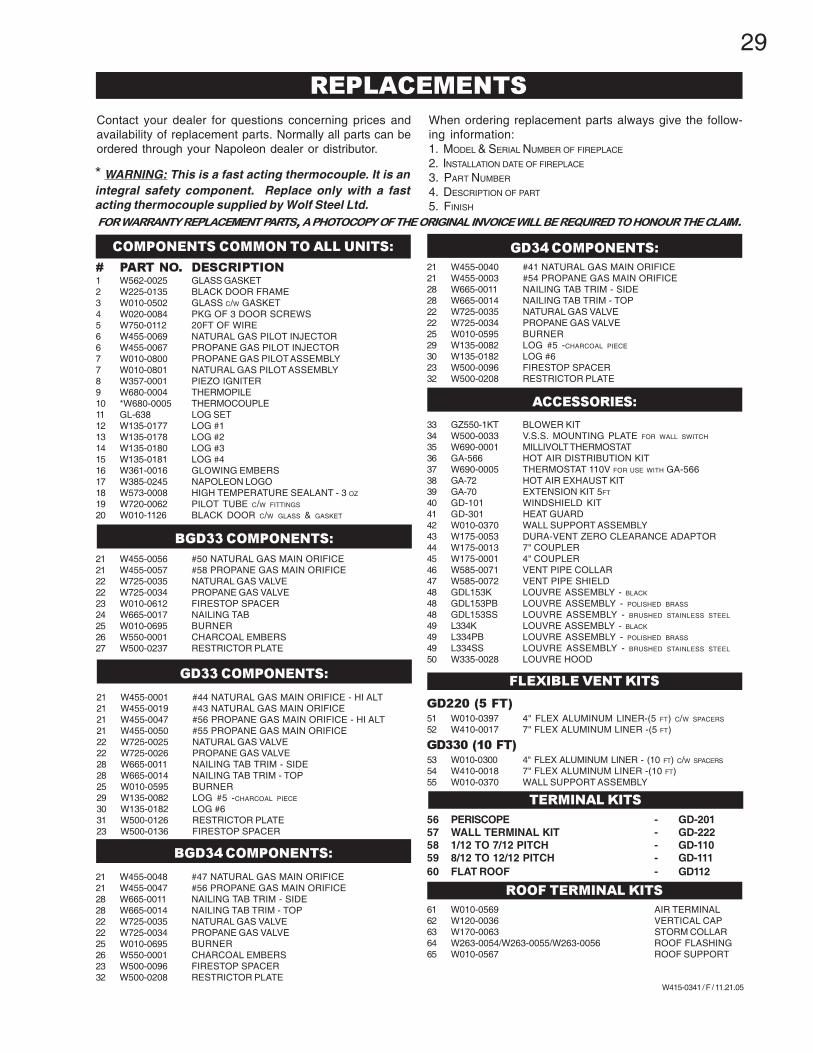
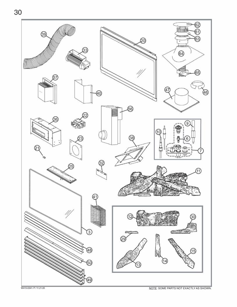
Contact your dealer for questions concerning prices andavailability of replacement parts. Normally all parts can beordered through your Napoleon dealer or distributor.
When ordering replacement parts always give the follow-ing information:1. MODEL & SERIAL NUMBER OF FIREPLACE
2. INSTALLATION DATE OF FIREPLACE
3. PART NUMBER
4. DESCRIPTION OF PART
5. FINISH
FOR WARRANTY REPLACEMENT PARTS, A PHOTOCOPY OF THE ORIGINAL INVOICE WILL BE REQUIRED TO HONOUR THE CLAIM.
# PART NO. DESCRIPTION1 W562-0025 GLASS GASKET2 W225-0135 BLACK DOOR FRAME3 W010-0502 GLASS C/W GASKET4 W020-0084 PKG OF 3 DOOR SCREWS5 W750-0112 20FT OF WIRE6 W455-0069 NATURAL GAS PILOT INJECTOR6 W455-0067 PROPANE GAS PILOT INJECTOR7 W010-0800 PROPANE GAS PILOT ASSEMBLY7 W010-0801 NATURAL GAS PILOT ASSEMBLY8 W357-0001 PIEZO IGNITER9 W680-0004 THERMOPILE10 *W680-0005 THERMOCOUPLE11 GL-638 LOG SET12 W135-0177 LOG #113 W135-0178 LOG #214 W135-0180 LOG #315 W135-0181 LOG #416 W361-0016 GLOWING EMBERS17 W385-0245 NAPOLEON LOGO18 W573-0008 HIGH TEMPERATURE SEALANT - 3 OZ
19 W720-0062 PILOT TUBE C/W FITTINGS
20 W010-1126 BLACK DOOR C/W GLASS & GASKET
* WARNING: This is a fast acting thermocouple. It is anintegral safety component. Replace only with a fastacting thermocouple supplied by Wolf Steel Ltd.
REPLACEMENTS
COMPONENTS COMMON TO ALL UNITS:
21 W455-0001 #44 NATURAL GAS MAIN ORIFICE - HI ALT21 W455-0019 #43 NATURAL GAS MAIN ORIFICE21 W455-0047 #56 PROPANE GAS MAIN ORIFICE - HI ALT21 W455-0050 #55 PROPANE GAS MAIN ORIFICE22 W725-0025 NATURAL GAS VALVE22 W725-0026 PROPANE GAS VALVE28 W665-0011 NAILING TAB TRIM - SIDE28 W665-0014 NAILING TAB TRIM - TOP25 W010-0595 BURNER29 W135-0082 LOG #5 -CHARCOAL PIECE
21 W455-0040 #41 NATURAL GAS MAIN ORIFICE21 W455-0003 #54 PROPANE GAS MAIN ORIFICE28 W665-0011 NAILING TAB TRIM - SIDE28 W665-0014 NAILING TAB TRIM - TOP22 W725-0035 NATURAL GAS VALVE22 W725-0034 PROPANE GAS VALVE25 W010-0595 BURNER29 W135-0082 LOG #5 -CHARCOAL PIECE
35 W690-0001 MILLIVOLT THERMOSTAT36 GA-566 HOT AIR DISTRIBUTION KIT37 W690-0005 THERMOSTAT 110V FOR USE WITH GA-56638 GA-72 HOT AIR EXHAUST KIT39 GA-70 EXTENSION KIT 5FT
61 W010-0569 AIR TERMINAL62 W120-0036 VERTICAL CAP63 W170-0063 STORM COLLAR64 W263-0054/W263-0055/W263-0056 ROOF FLASHING65 W010-0567 ROOF SUPPORT
21 W455-0048 #47 NATURAL GAS MAIN ORIFICE21 W455-0047 #56 PROPANE GAS MAIN ORIFICE28 W665-0011 NAILING TAB TRIM - SIDE28 W665-0014 NAILING TAB TRIM - TOP22 W725-0035 NATURAL GAS VALVE22 W725-0034 PROPANE GAS VALVE25 W010-0695 BURNER26 W550-0001 CHARCOAL EMBERS23 W500-0096 FIRESTOP SPACER32 W500-0208 RESTRICTOR PLATE
BGD34 COMPONENTS:
GD34 COMPONENTS:
BGD33 COMPONENTS:
21 W455-0056 #50 NATURAL GAS MAIN ORIFICE21 W455-0057 #58 PROPANE GAS MAIN ORIFICE22 W725-0035 NATURAL GAS VALVE22 W725-0034 PROPANE GAS VALVE23 W010-0612 FIRESTOP SPACER24 W665-0017 NAILING TAB25 W010-0695 BURNER26 W550-0001 CHARCOAL EMBERS27 W500-0237 RESTRICTOR PLATE
GD33 COMPONENTS:
30
W415-0341 / F / 11.21.05 NOTE: SOME PARTS NOT EXACTLY AS SHOWN.
31
W415-0341 / F / 11.21.05
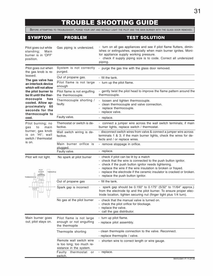
Pilot goes out whilestanding; Mainburner is in 'OFF'position.
Gas piping is undersized. - turn on all gas appliances and see if pilot flame flutters, dimin-ishes or extinguishes, especially when main burner ignites. Moni-tor appliance supply working pressure.- check if supply piping size is to code. Correct all undersizedpiping.
Pilot goes out whenthe gas knob is re-leased.The gas valve hasan interlock devicewhich will not allowthe pilot burner tobe lit until the ther-mocouple hascooled. Allow ap-proximately 60seconds for thethermocouple tocool.
System is not correctlypurged.
- purge the gas line with the glass door removed.
Out of propane gas. - fill the tank.
Pilot flame is not largeenough
- turn up the pilot flame.
- gently twist the pilot head to improve the flame pattern around thethermocouple.
Pilot flame is not engulfingthe thermocouple.
Thermocouple shorting /faulty.
- loosen and tighten thermocouple.- clean thermocouple and valve connection.- replace thermocouple.- replace valve.
Faulty valve. - replace.
Pilot burning; nogas to mainburner; gas knobis on 'HI'; wallswitch / thermostatis on.
Themostat or switch is de-fective.
- connect a jumper wire across the wall switch terminals; if mainburner lights, replace switch / thermostat.
Main burner orifice isplugged.
- remove stoppage in orifice.
Faulty valve. - replace.
Wall switch wiring is de-fective.
- disconnect switch wires from valve & connect a jumper wire acrossterminals 1 & 3; if the main burner lights, check the wires for de-fects and / or replace wires.
Pilot will not light. - check if pilot can be lit by a match- check that the wire is connected to the push button ignitor.- check if the push button ignitor needs tightening.- replace the wire if the wire insulation is broken or frayed.- replace the electrode if the ceramic insulator is cracked or broken.- replace the push button ignitor.
No spark at pilot burner
- fill the tank.Out of propane gas
Spark gap is incorrect - spark gap should be 0.150" to 0.175" (5/32" to 11/64" approx.)from the electrode tip and the pilot burner. To ensure proper elec-trode location, tighten securing nut (finger tight plus 1/4 turn).
No gas at the pilot burner - check that the manual valve is turned on.- check the pilot orifice for blockage.- replace the valve.- call the gas distributor.
Main burner goesout; pilot stays on.
Pilot flame is not largeenough or not engulfingthe thermopile
- turn up pilot flame.- replace pilot assembly.
Thermopile shorting - clean thermopile connection to the valve. Reconnect.- replace thermopile / valve.
Remote wall switch wireis too long; too much re-sistance in the system.
- shorten wire to correct length or wire gauge.
Faulty thermostat orswitch.
- replace.
TROUBLE SHOOTING GUIDE
BEFORE ATTEMPTING TO TROUBLESHOOT, PURGE YOUR UNIT AND INITIALLY LIGHT THE PILOT AND THE MAIN BURNER WITH THE GLASS DOOR REMOVED.
SYMPTOM PROBLEM TEST SOLUTION
32
W415-0341 / F / 11.21.05
P
I
AB
PILOT
N O
L
O
T
HI
LO
FF O
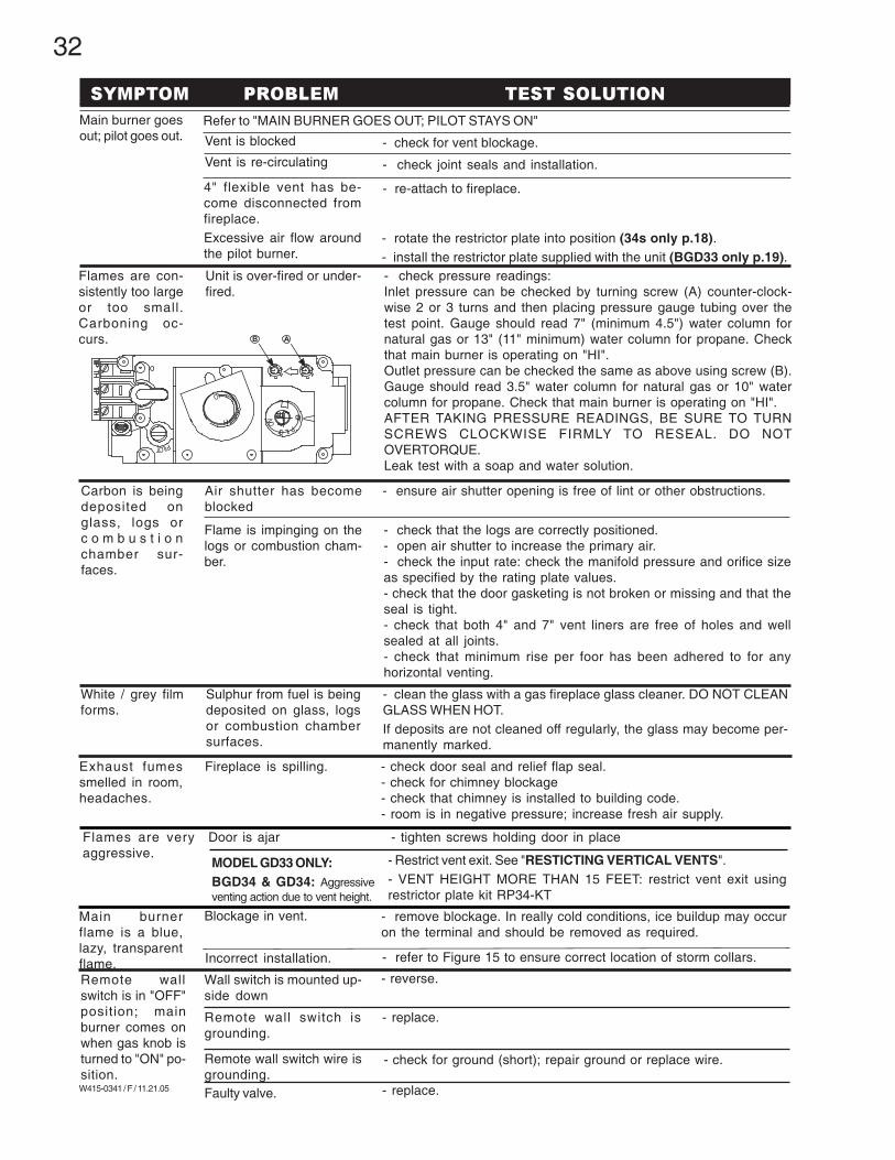
Main burner goesout; pilot goes out.
Refer to "MAIN BURNER GOES OUT; PILOT STAYS ON"
Vent is blocked
Vent is re-circulating
- check for vent blockage.
- check joint seals and installation.
4" flexible vent has be-come disconnected fromfireplace.Excessive air flow aroundthe pilot burner.
- re-attach to fireplace.
Flames are con-sistently too largeor too small.Carboning oc-curs.
- check pressure readings:Inlet pressure can be checked by turning screw (A) counter-clock-wise 2 or 3 turns and then placing pressure gauge tubing over thetest point. Gauge should read 7" (minimum 4.5") water column fornatural gas or 13" (11" minimum) water column for propane. Checkthat main burner is operating on "HI".Outlet pressure can be checked the same as above using screw (B).Gauge should read 3.5" water column for natural gas or 10" watercolumn for propane. Check that main burner is operating on "HI".AFTER TAKING PRESSURE READINGS, BE SURE TO TURNSCREWS CLOCKWISE FIRMLY TO RESEAL. DO NOTOVERTORQUE.Leak test with a soap and water solution.
Unit is over-fired or under-fired.
Carbon is beingdeposited onglass, logs orc o m b u s t i o nchamber sur-faces.
Flame is impinging on thelogs or combustion cham-ber.
- check that the logs are correctly positioned.- open air shutter to increase the primary air.- check the input rate: check the manifold pressure and orifice sizeas specified by the rating plate values.- check that the door gasketing is not broken or missing and that theseal is tight.- check that both 4" and 7" vent liners are free of holes and wellsealed at all joints.- check that minimum rise per foor has been adhered to for anyhorizontal venting.
Air shutter has becomeblocked
- ensure air shutter opening is free of lint or other obstructions.
White / grey filmforms.
Sulphur from fuel is beingdeposited on glass, logsor combustion chambersurfaces.
- clean the glass with a gas fireplace glass cleaner. DO NOT CLEANGLASS WHEN HOT.If deposits are not cleaned off regularly, the glass may become per-manently marked.
Exhaust fumessmelled in room,headaches.
Fireplace is spilling. - check door seal and relief flap seal.- check for chimney blockage- check that chimney is installed to building code.- room is in negative pressure; increase fresh air supply.
Main burnerflame is a blue,lazy, transparentflame.
Blockage in vent. - remove blockage. In really cold conditions, ice buildup may occuron the terminal and should be removed as required.
- refer to Figure 15 to ensure correct location of storm collars.Incorrect installation.
Remote wallswitch is in "OFF"position; mainburner comes onwhen gas knob isturned to "ON" po-sition.
Wall switch is mounted up-side down
- reverse.
Faulty valve. - replace.
- replace.Remote wall switch isgrounding.
- check for ground (short); repair ground or replace wire.Remote wall switch wire isgrounding.
SYMPTOM PROBLEM TEST SOLUTION
- Restrict vent exit. See "RESTICTING VERTICAL VENTS".- VENT HEIGHT MORE THAN 15 FEET: restrict vent exit usingrestrictor plate kit RP34-KT
MODEL GD33 ONLY:BGD34 & GD34: Aggressiveventing action due to vent height.
Flames are veryaggressive.
- tighten screws holding door in placeDoor is ajar
- rotate the restrictor plate into position (34s only p.18).- install the restrictor plate supplied with the unit (BGD33 only p.19).