Please record the following information, which is specific to this piece of equipment, in the space provided. Our Parts/Service Department will need these numbers to properly respond to any of your requests.
Instruction Manual: GFH-NT 1500-4000 15 OCT 2014 Model #:___________________________ Serial #____________________________
DISCLAIMER: NOVATEC, Inc. shall not be liable for errors contained in this Instruction Manual nor for misinterpretation of information contained herein. NOVATEC shall not, in any event, be held liable for any special, indirect or consequential damages in connection with performance or use of this information.
2.0 GETTING STARTED SUMMARY FOR QUALIFIED TECHNICIANS
If you are experienced and qualified, starting and operating the gas heater is simple and easy. Connect the gas line and flue to the heater. Apply the correct power and interlock wiring from the process motor auxiliary contact (field supplied). Check for the proper rotation of the motors. Install the process thermocouple into the hopper inlet duct and turn the burner on. Adjust the temperature controller set point as needed and you are ready to go. The purpose of the preceding getting started summary is to illustrate the basic installation and operating procedures. The details for the above summary are shown on the following pages. All personnel, including those experienced and qualified, should read carefully the entire instruction
manual. DO NOT OPERATE THIS GAS HEATER UNLESS THIS INSTRUCTION MANUAL IS
COMPLETELY UNDERSTOOD.
2.1 WARNINGS
WARNING Before using this equipment, read in detail the various manufacturers’ bulletins found in this instruction manual. They contain information in regards to the safe installation and operation of this equipment and the devices used on the gas heater assembly. The warnings and cautions should be understood and followed before operating this equipment.
WARNING As with any gas appliance at home or work, if you detect the odor of gas, immediately: Turn off the manual shut off valve. Contact a qualified technician to determine and repair the gas leak as necessary.
WARNING Your Novatec GFH Series Natural Gas Fired Process Heater is equipped with safety devices for
your protection. Do not override these devices. Only qualified personnel should make adjustments and repairs.
CAUTION Only qualified technicians should install the gas and flue lines. Local and national codes need to be followed.
WARNING Only clean filtered process air should enter the heat exchanger. Plastic dust, regrind and or pellets will clog the heat exchanger and would represent a fire hazard. The heat exchanger is not easily cleaned and may have to be replaced if contaminated. Do not operate the gas fired heater assembly if plastic dust, regrind or pellets have entered the exchanger as this condition may cause a fire.
WARNING
The user has the responsibility for establishing a program of inspection, testing, and maintenance
with documentation performed at least annually for every gas safety component (Reference NFPA 86 – Ovens and Furnaces, 5-2.5.2)
WARNING
All Lock-Out/Tag-Out OSHA or other safety procedures must be followed. Do not clean, service, or maintain this equipment unless all safety precautions are followed. Only qualified technicians should be allowed to clean, service, or maintain this equipment.
Novatec's highly efficient indirect fired gas heater is designed to be a more economical, durable alternative to electrically heated units. Like all Novatec products, the GFH-Series heaters incorporate rigorous design and manufacturing standards as well as the highest quality materials. The gas heater complies with NFPA-86 standards and utilizes components that carry UL, FM, and AGA markings. IRI Gas Trains and other options are available. The Control Panel is UL/C-UL Classified and includes a Disconnect Switch. At the heart of every Novatec GFH-Series heater is a nozzle mixing gas burner manufactured by Eclipse, Inc., who is the acknowledged leader in industrial process air heating systems. The fixed air nozzle mixing burner's unique features include a high turndown temperature range, which allows for the processing of a variety of resins requiring different drying temperatures. The system includes a heavy-duty stainless steel heat exchanger. This advance design typically provides operating efficiencies up to and above 90% depending on conditions, and results in a cool flue temperature. It totally isolates combustion products from the process air stream. The GFH series components that are exposed to extreme heat are manufactured to the highest standard, which guarantee low maintenance and a longer life. The result is a safe, more cost-effective, indirect fired gas dryer.
FEATURES Safety
NFPA 86 Gas Train
UL/C-UL Listed Control Panel
Disconnect Switch
Interface Equipment PHH, CDM, CD, MPC or NPD
Reduces energy costs
Up to 90% efficiency
Stainless Steel Heat Exchanger
Stainless Steel Combustion Chamber
Low combustion chamber temperature assures high efficiency and reduced emissions
Eclipse Nozzle Mixing Burner
2 year Warranty
High density industrial insulation assures maximum efficiency and lower case temperature
Total isolation of combustion air from process air
Precise temperature control maintained across a full range of temperature settings while maintaining up to 90% efficiencies
Low flue temperatures are the result of highly efficient heat transfer
When unpacking, caution should be exercised to see that the equipment is not handled roughly. The crate must be removed carefully. The machine must not be used to pry against when removing the crate. Gas-fired heaters are usually shipped completely assembled and require no further attention prior to installation.
5.0 GENERAL INSPECTION
When the unit is unpacked, make a visual inspection looking for missing parts or damage, which may have occurred during shipment. All electrical and mechanical connections should be checked for tightness, as vibration during transit may cause them to loosen.
6.0 GAS LINE & FLUE INSTALLATION
Only qualified technicians familiar with local and national codes should install the gas line and the flue. The exhaust flue should be as short as possible. A typical installation would include a drip leg.
Caution: Check for gas leaks using appropriate devices.
7.0 ELECTRICAL INSTALLATION
Connect the proper power supply (check nameplate) through a main line disconnect (field supplied) to terminal connections L1, L2, L3 and ground in the control cabinet. This is only power required as the unit is completely pre-wired and supplied with a control voltage transformer to supply 110 volts to the control circuit. Connect the interlock wiring from the desiccant dryer control panel to the gas heater control panel as shown on the electrical schematics for each assembly. Verify the correct rotation of the combustion blower assembly with the directional labels on the unit. Install the process thermocouple in the hopper inlet duct. Refer to the electrical wiring schematics for complete details.
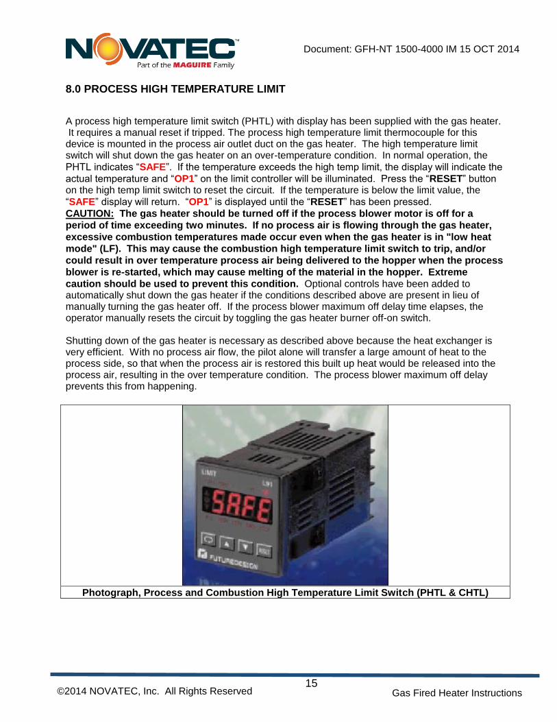
A process high temperature limit switch (PHTL) with display has been supplied with the gas heater. It requires a manual reset if tripped. The process high temperature limit thermocouple for this device is mounted in the process air outlet duct on the gas heater. The high temperature limit switch will shut down the gas heater on an over-temperature condition. In normal operation, the
PHTL indicates “SAFE”. If the temperature exceeds the high temp limit, the display will indicate the
actual temperature and “OP1” on the limit controller will be illuminated. Press the “RESET” button on the high temp limit switch to reset the circuit. If the temperature is below the limit value, the
“SAFE” display will return. “OP1” is displayed until the “RESET” has been pressed.
CAUTION: The gas heater should be turned off if the process blower motor is off for a
period of time exceeding two minutes. If no process air is flowing through the gas heater,
excessive combustion temperatures made occur even when the gas heater is in "low heat
mode" (LF). This may cause the combustion high temperature limit switch to trip, and/or
could result in over temperature process air being delivered to the hopper when the process
blower is re-started, which may cause melting of the material in the hopper. Extreme
caution should be used to prevent this condition. Optional controls have been added to automatically shut down the gas heater if the conditions described above are present in lieu of manually turning the gas heater off. If the process blower maximum off delay time elapses, the operator manually resets the circuit by toggling the gas heater burner off-on switch. Shutting down of the gas heater is necessary as described above because the heat exchanger is very efficient. With no process air flow, the pilot alone will transfer a large amount of heat to the process side, so that when the process air is restored this built up heat would be released into the process air, resulting in the over temperature condition. The process blower maximum off delay prevents this from happening.
Photograph, Process and Combustion High Temperature Limit Switch (PHTL & CHTL)
A combustion high temperature limit switch (CHTL) with display has been supplied with the gas heater. It requires a manual reset if tripped. The combustion high temperature limit thermocouple for this device is mounted in the flue outlet duct on the gas heater. The high temperature limit switch will shut down the gas heater on an over-temperature condition. In normal operation, the
CHTL indicates “SAFE”. If the temperature exceeds the high temp limit, the display will indicate the
actual temperature and “OP1” on the limit controller will be illuminated. Press the “RESET” button on the high temp limit switch to reset the circuit. If the temperature is below the limit value, the
“SAFE” display will return. “OP1” is displayed until the “RESET” has been pressed.
10.0 NOVATEC GAS FIRED HEATER SEQUENCE OF OPERATION
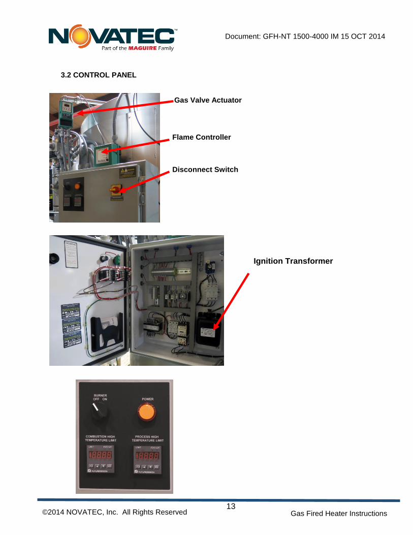
A control box is attached to the gas fired process heater assembly. It contains the combustion motor starter, ignition transformer, burner controller, “Power” pilot light, and Disconnect switch. The gas fired heater assembly, along with the desiccant dryer and drying hopper, makes a complete drying system. There are two control boxes in this system. The first one is located on the desiccant dryer. The second one is located on the gas heater. The process temperature set point is programmed with the NOVATOUCH PLC Touch Panel; that is located on the desiccant dryer. The process blower on the dryer is electrically interlocked with the gas-fired heater. If the process blower turns off, the gas fired process heater will go to low fire (low heat mode). If the process blower is off for longer than two minutes, the burner will automatically be turned off. Restarting the burner requires the system to be manually reset. This is done by toggling the burner off/on switch on the Gas Heater control box to the off position and then back on to reset the process blower maximum off delay circuit.
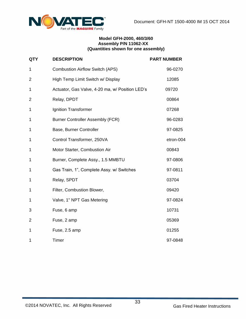
1.0 When the main disconnect switch (1DISC) is closed, the control transformer (1T) is energized along with the "Power" pilot light on the gas heater control panel.
2.0 The process blower on the desiccant dryer should be on to start the gas-fired heater. If the process blower is not on, the process blower maximum off delay circuit may elapse, and the flame controller will stop the sequence.
2.1 The Gas Heater Start Contact from the NOVATOUCH PLC desiccant dryer control must be closed to start the burner. This contact is also toggled off and then on to reset the process blower maximum off delay circuit if the process blower is off for more then 2 minutes.
2.2 If the Safety Interlocks, consisting of the gas heater start contact (CR), the low gas pressure switch (LGPS), the high gas pressure switch (HGPS), the combustion air high temperature limit switch (CHTL), the process air high temperature limit switch (PHTL), the Dryer Process Blower maximum off delay timer contact (1TDRA), the combustion blower motor starter overload contact (1OL), and the Combustion Blower Motor thermal protector (TP) are all closed, the combustion blower will be energized by the burner controller. If the combustion air pressure switch (APS) and the proof of closure switch (POC) are closed, the air purge will begin. A neon indicator light will be on and is visible through the clear plastic cover on the LGPS and HGPS when these switches are closed. The POC has two indicator lights, orange showing that the valve is closed, and green showing that the valve is open. The burner controller controls the air purge. The total purge time is 1 minute.
2.3 If the CR, LGPS, HGPS, CHTL, PHTL, 1TDRA, 1OL, TP, and POC are not closed, the sequence will not begin and the “Interlocks Closed” green LED on the flame controller will not be on. If any or all open after the flame is on, the flame will go out, the green “Interlocks Closed” LED will be off, and the sequence will not start until they are closed.
3.0 After 1 minute of air purging, the automatic 10 seconds trial for ignition is initiated.
Simultaneously, the pilot gas solenoid valves (1SOL & 3SOL) and the ignition transformer (2T) are energized so that the igniter gives off a continuous spark.
If a flame is detected by the flame rod within the 10-second period, the ignition transformer is de-energized (The pilot gas solenoids remain open). A red LED located in the flame signal test port on the flame controller will glow. The dual modular main gas safety shutoff valves are simultaneously energized. The dual modular main gas safety shutoff valves (2SOL) open slowly so that the pilot is not overloaded. The APS remains closed. The neon indicator light (see section 2.2) in the LGPS and HGPS will remain on. The POC indicator light will turn from orange to green.
4.0 If a problem occurs, the burner controller will lock out the sequence. The "Flame Failure” red LED on the flame controller will glow. The flame controller must be manually reset to start another sequence. The reset button is located on the flame controller. Complete operational details for the flame controller can be found in the Veri-Flame Purge Flame Monitoring Controller Series 5602 & 5605 bulletin located elsewhere in this manual.
5.0 If the combustion high temperature limit with Display (CHTL) opens, it must be manually reset to initiate another complete cycle, starting with the air purge sequence (item 2.1). The reset button is located on the CHTL. The flame controller must also be reset.
6.0 If the process air high temperature limit switch (PHTL) opens, it must be manually reset to initiate another complete cycle, starting with the air purge sequence (item 2.1). The reset button is located on the PHTL. The flame controller must also be reset.
7.0 The temperature of the process air is controlled by the NOVATOUCH PLC Control that is located in the desiccant dryers main control box. A 4-20 ma signal is sent to the modulating actuator that controls the main gas automatic butterfly valve in a range from closed (15 degrees) to open (90 degrees).
8.0 If the Desiccant Dryers Process Blower Motor is not running the main gas automatic butterfly valve will be driven to the closed position (LF). If the process blower remains off for longer then 2 minutes, the process blower maximum off delay timer contact will open, shutting down the burner. Toggling the gas heater start contact from the NOVATOUCH PLC control located at the desiccant dryer resets the process blower maximum off delay circuit. The NOVATOUCH PLC control automatically toggles the gas heater start contact when the alarm is reset using the NOVATOUCH PLC touch panel on the desiccant dryer.
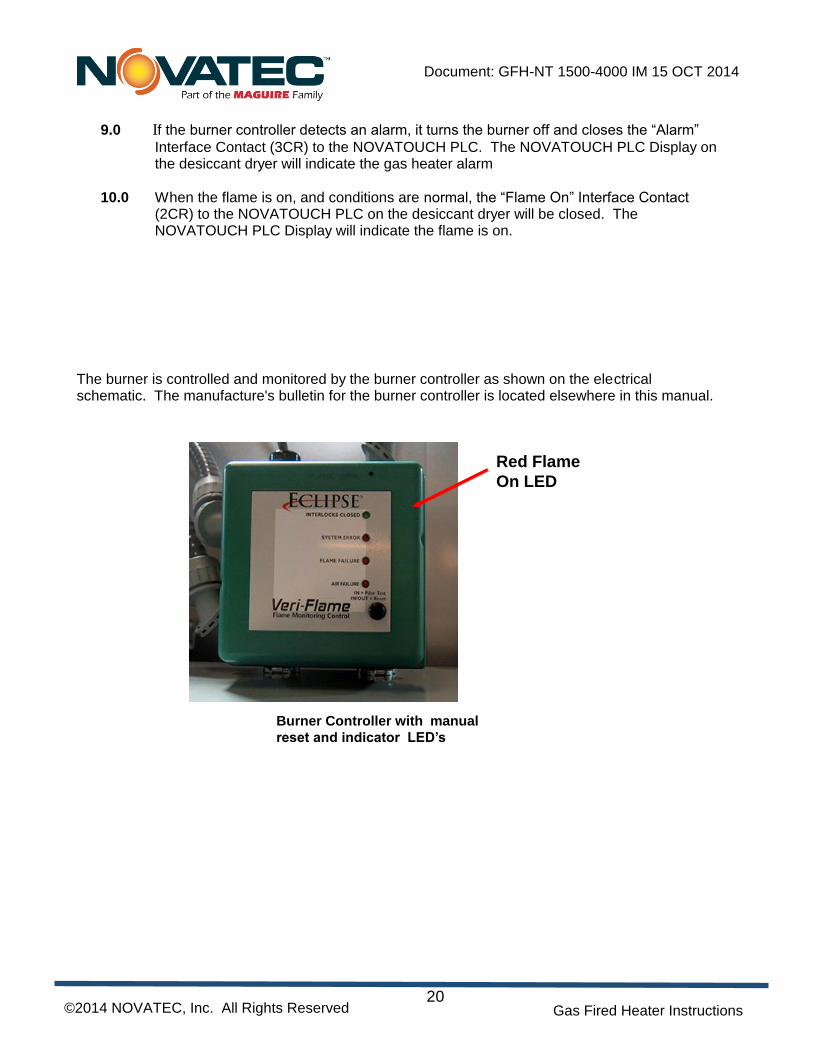
9.0 If the burner controller detects an alarm, it turns the burner off and closes the “Alarm”
Interface Contact (3CR) to the NOVATOUCH PLC. The NOVATOUCH PLC Display on the desiccant dryer will indicate the gas heater alarm
10.0 When the flame is on, and conditions are normal, the “Flame On” Interface Contact (2CR) to the NOVATOUCH PLC on the desiccant dryer will be closed. The NOVATOUCH PLC Display will indicate the flame is on.
The burner is controlled and monitored by the burner controller as shown on the electrical schematic. The manufacture's bulletin for the burner controller is located elsewhere in this manual.
The process air temperature is set by adjusting the Process Temperature Set point on the
NOVATOUCH PLC Controls on the desiccant Dryer. Note that adjusting the set point under 100 F disables the Flame On Alarm, allowing the Gas fired heater to be shut down by its own disconnect switch while the dryer continues to operate Complete details on operating the NOVATOUCH PLC controls can be found in the manual that is supplied separately.
12.0 GAS HEATER SETUP PROCEDURES
NOTE: The gas heater has been fully adjusted at the factory and field adjustments are usually not necessary. These procedures are shown only as a reference should it become necessary to make
field adjustments. Only qualified technicians should make these adjustments. Field adjustments may be necessary to compensate for installation variations or if components are
replaced. Adjustments in addition to those shown may be needed. The information in this
manual is provided as a guideline for professionals with knowledge of gas heating
appliances, and therefore does not include specific instructions to cover every situation.
Set the main gas trim valve full open. Turn the pilot gas-metering valve to full open. Adjust the main and pilot regulators to half-open. Adjust the combustion blower damper half-open. Set/check/adjust air and gas pressures as required using a water manometer or other appropriate apparatus according to the procedure that follows. Check for gas leaks at all connections with gas leak detector fluid or suitable electronic device. Make sure the gas is turned off when test plugs are removed to install temporary fittings and when the plugs are re-installed after testing. Some adjustments are made with the flame on as noted. The others are made with the flame off and only the blowers energized. The burner is controlled and monitored by the burner controller as shown on the electrical schematic. The manufacture's bulletin for the burner controller is located elsewhere in this manual.
1.0 ADJUST COMBUSTION AIR PRESSURE SWITCH (APS)
1.1 The APS is open when the heater is off or if combustion airflow is not present. The switch should be adjusted to the setting as shown in the Engineering Data section under Instrument Settings.
2.0 ADJUST LOW GAS PRESSURE SWITCH (LGPS)
2.1 The LGPS is open if the main gas pressure is low. The switch should be adjusted to 16" WC. The neon indicator will glow (visible through the clear plastic cover on the switch) when the switch is closed.
3.1 The HGPS is open if the main gas pressure is low. The switch should be adjusted to 36" WC. The neon indicator will glow (visible through the clear plastic cover on the switch) when the switch is closed.
4.0 ADJUST PROOF OF CLOSURE SWITCH (POC)
4.1 The POC switch should be in the NO position (orange neon indicator light on) when the main safety shutoff valve is closed. When the main safety shutoff valve is open, the POC switch should be in the NC position (green neon indicator light on). With the main safety shutoff valve closed, remove the clear cover on the POC. Turn the white knob counter clockwise (CCW) until it comes to the stop. The circuit between the terminal COM and NO should be open. Then turn the knob slowly cw until the switch makes. Make sure the POC is working properly before putting the valve into service.
5.0 ADJUST COMBUSTION AIR STATIC PRESSURE
5.1 Connect a manometer to tap A. (Reference SK-946A)
5.2 Adjust the damper on the combustion blower discharge to achieve the static pressure (± 0.5" WC) as shown in the Engineering Data section under Instrument Settings.
5.3 Lock the damper in place.
6.0 ADJUST MAIN GAS STATIC PRESSURE
6.1 The flame is on for this setting. Connect a manometer to tap B. (Reference SK-946A)
6.2 Adjust the main gas regulator to achieve the static pressure (± 0.5" WC) as shown in the Engineering Data section under Instrument Settings.
7.0 FLUE ANALYSIS
7.1 The flame is on for this test. With a combustion analyzer, measure the oxygen
content of the flue exhaust. It should be greater than 0% when the automatic main gas valve is fully open. When the burner is at set point with little modulation of the automatic main gas valve, the readings are typically in the 1 to 16% range. Good flue analysis and performance is achieved by balancing the combustion air and the amount of gas. Small adjustments should be all that is required if all the parameters are within a normal range.
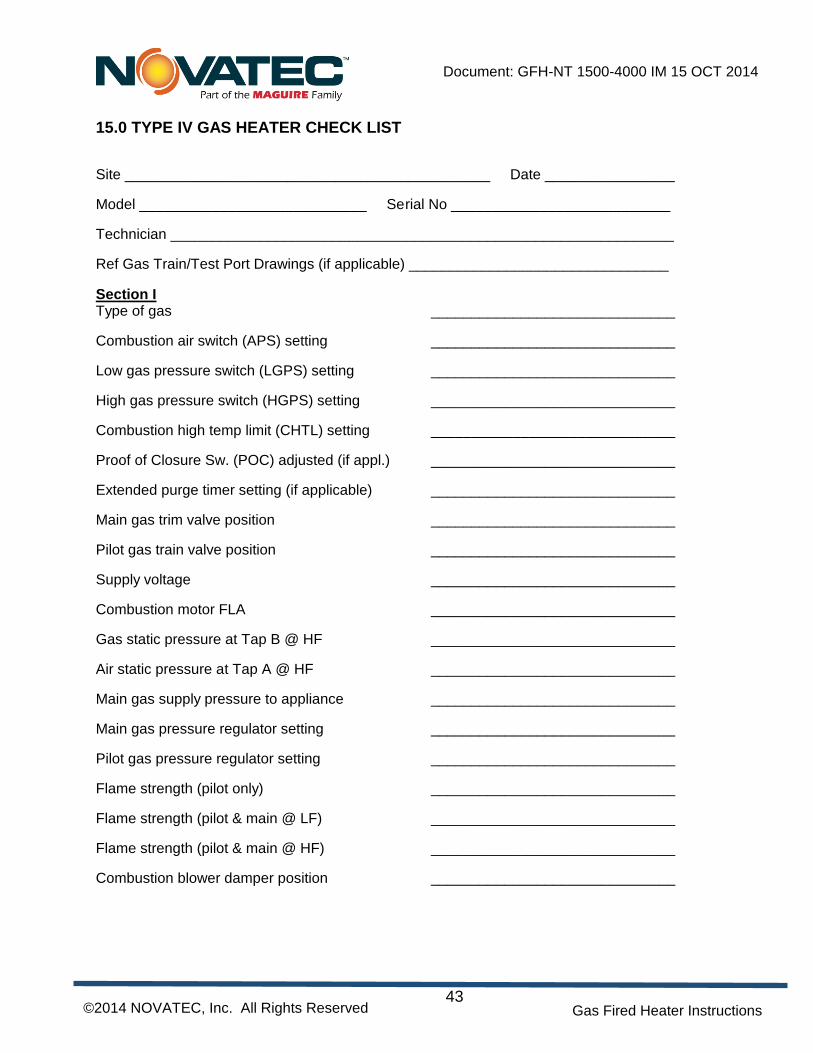
8.1 After the gas heater has been properly installed and adjusted, complete a Gas Heater
Check List for each heater. A blank copy of a typical Check List can be found in this manual. Keep the record in a safe place as it provides useful information to help adjust the gas heater if it becomes necessary to replace component.
It is recommended that maintenance and inspection is done on a scheduled basis. Maintenance requirements will naturally vary widely for each installation and with specific operating conditions. It is suggested that a complete inspection be performed with necessary maintenance at the end of the first week, the first month, the first three months, and the first six months. These inspections will be indicative of how often future maintenance will be necessary. Suggested maintenance and inspection items are shown on the following pages.
WARNING The user has the responsibility for establishing a program of inspection, testing, and maintenance with documentation performed at least annually for every gas safety component (Reference NFPA 86 – Ovens and Furnaces, 5-2.5.2)
EVERY MONTH A. Inspect the combustion air filter. Clean or replace as required. B. Check for gas leaks using an approved leak detector.
EVERY 3 MONTHS A. Units equipped with ball bearing motors are factory greased and should be re-lubricated with a high-grade ball bearing grease.
NOTE: Most units are equipped with permanently lubricated bearings and no lubrication is required. All motors should be examined on an individual basis.
When adding lubricant:
1. Remove filler plugs at the bearings and install grease fittings suitable to your grease gun.
Also remove the drain plugs at the bearings. 2. Add ball bearing grease until all of the old grease is expelled through the drain hole. 3. Run motor with drain plug removed to eliminate excess grease. 4. Clean and replace drain plugs.
B. Check motor(s) amperage C. Check all electrical connections to make sure that they have not become loose, especially those
connections at motor starters. D. Check all mechanical connections i.e. collar setscrews, etc., to make sure that they have not
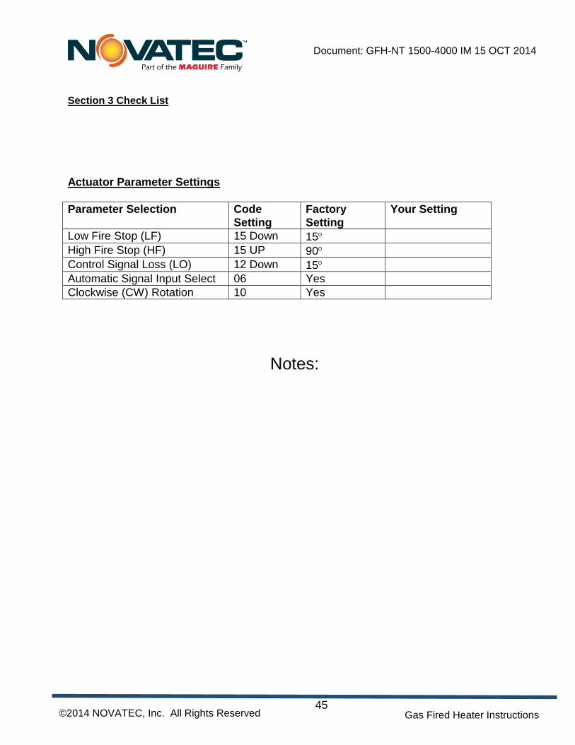
13.1 GAS VALVE ACTUATOR CW ADJUSTMENT AND PROGRAMMING
The gas butterfly valve rotary actuator is a keypad programmable, direct coupled, modulating motor that has been fully programmed at the factory. It has been set at the factory to rotate 75 degrees CW from minimum to maximum position depending on the 4-20 ma signal received from the temperature controller. The gas butterfly valve rotates a maximum of 75 degrees from full closed to full open. The Low Fire (LF) closed position is 15 degrees and the High Fire (HF) full open position is 90 degrees. If the actuator needs to be replaced, the new one will need to be setup as follows: 1.0 Provide temporary power to the actuator and drive it to the minimum position. 2.0 Set the actuator’s shaft rotation direction to CW (as viewed while facing the actuator’s keypad)
to match that of the butterfly valve.
2.1 Press the ENTER key; the message “SC” will appear on the display.
2.2 Press the UP or DOWN key until the number “10” appears in the display.
2.3 Press the RESET key to complete the sequence. 3.0 Set the actuator’s lowest shaft travel position (Low Fire Stop) (LF).
3.1 Press the ENTER key; the message “SC” will appear on the display.
3.2 Press the UP or DOWN key until the number “15” appears on the display.
3.3 Press the RESET key; the message “PG” will appear on the display.
3.4 Press the DOWN key; the message “LF” will appear on the display.
3.5 Press the UP or Down key until the number “15” (“15” degree of shaft rotation) appears on the display.
3.6 Press the RESET key to complete the sequence. 4.0 Set the actuator’s highest shaft travel position (High Fire Stop) (HF).
4.1 Press the ENTER key; the message “SC” will appear on the display.
4.2 Press the UP or DOWN key until the number “15” appears on the display.
4.3 Press the RESET key; the message “PG” will appear on the display
4.4 Press the UP key; the message “HF” will appear on the display.
4.5 Press the UP or DOWN key until the number “90” (“75” degree of shaft rotation, 15 degree starting position plus 75 degree of rotation) appears on the display.
4.6 Press the RESET key to complete the sequence. 5.0 Set the actuator’s shaft position when control signal is zero (Control Signal Loss) (LO)
5.1 Press the ENTER key; the message “SC” will appear on the display.
5.2 Press the UP or DOWN key until the number “12” appears on the display.
5.3 Press the RESET key; the message PG will appear on the display.
5.4 Press the DOWN key; the message “LO” will appear on the display.
5.5 Press the UP or DOWN key until the number “15” (“15” degree shaft position) appears on the display (reference 3.0 above)
5.6 Press the RESET key to complete the sequence. 6.0 Remove temporary power. 7.0 Install the coupling to the actuator shaft with a 3 mm slotted spring pin. Insert the coupling onto
the shaft and align the coupling’s drive hole with the shaft hole. Press the spring pin through the coupling and shaft.
8.0 Verify that the rotation direction for the butterfly valve and actuator shaft match while the butterfly valve is in its minimum position.
9.0 Place the actuator in the orientation by which it will be attached to the mounting bracket. Slide
the actuator and coupling assembly onto the butterfly valve shaft and attach carefully. Take precaution not to move the butterfly valve from its minimum position setting.
10.0 Attach a M6 X 16 mm hex head bolt with flat and lock washers through the bracket to the actuator. Install the screw through the coupling, making sure it is in alignment with the hole in the butterfly valve.
11.0 Securely tighten the screw on the coupler. 12.0 Confirm the position and tightness of all connections. 13.0 Make all electrical connections and apply power. 14.0 Verify that the stroke motion is smooth over its entire range and that all parameters are
correct. 15.0 Adjust the process Temperature above ambient. Check that the actuator opens the gas
butterfly valve to within 2 degrees of full open but not more than the maximum rotation of the butterfly valve, which is 75 degrees. Adjust if necessary
There are other actuator parameters that are not used. Refer to the manufacturer’s bulletin located in the back section of this manual for further details. A helpful parameter when setting up the actuator is to change the operational mode from automatic
(based on the 4-20 ma input) to manual (actuator shaft position set by manually pushing the UP or
DOWN keys.
CAUTION: If you place the actuator in manual mode as described below, return to automatic
mode before operating the gas fired heater. Do not leave the gas fired process heater
unattended when in manual mode. 16.0 To place the actuator in manual mode (Manual Position Select):
16.1 Press the ENTER key; the message “SC” will appear on the display.
16.2 Press the UP or DOWN key until the number “05” appears in the display.
16.3 Press the RESET key to complete the sequence. 17.0 To return to automatic mode (Signal Input Select):
17.1 Press the ENTER key; the message “SC” will appear on the display.
17.2 Press the UP or DOWN key until the number “06” appears in the display.
17.3 Press the RESET key to complete the sequence. Below is a summary listing of the actuators setup parameters requiring adjustment and the factory settings. Refer to the manufacture's instruction manual in the back section of this manual for complete details.
QTY DESCRIPTION PART NUMBER 1 Combustion Blower Assembly, 1.15 Hp 09704 10 Ft. Ignition/Flame Rod Cable, Silicon, (Order per foot) 94-0140 1 Regulator, 3/4” NPT, Main Gas, Modular 98-0582 1 Main Gas Valve, 3/4” NPT, Dual Body, Modular 98-0584 1 Low Main Gas Pressure Switch, Modular, 2-20” WC 98-0586 1 High Main Gas Pressure Switch, Modular, 12-60” WC 98-0587 1 Position Indicator, Modular Gas Valve 98-0589 2 Flange with O-Ring, 3/4” NPT Modular Gas Valve 98-0590 1 Regulator, Pilot Gas, 3/8 “ NPT, Square Body 10428 1 Shutoff/Adjustable Orifice Valve, Pilot Gas, 1/4 NPT 98-0580 2 Pilot Gas Shutoff Solenoid Valve, 115 VAC, 3/8 NPT 98-0581 2 Main Gas Shutoff Ball Valve with Test Port, 3/4” NPT 95-1973 1 Mounting Kit for 09720 Actuator w/bracket/shaft coupler 09721 1 Spark Plug, Gas Burner 98-0577 1 Flame Rod, Gas Burner 98-0578 1 Combustion Air Flow Butterfly Valve, 1-1/2” NPT 94-1804 2 Rajah Fitting, 90 Deg., Flame Rod and Spark Plug 07269 1 Proof of Closure Switch (POC) 98-0588
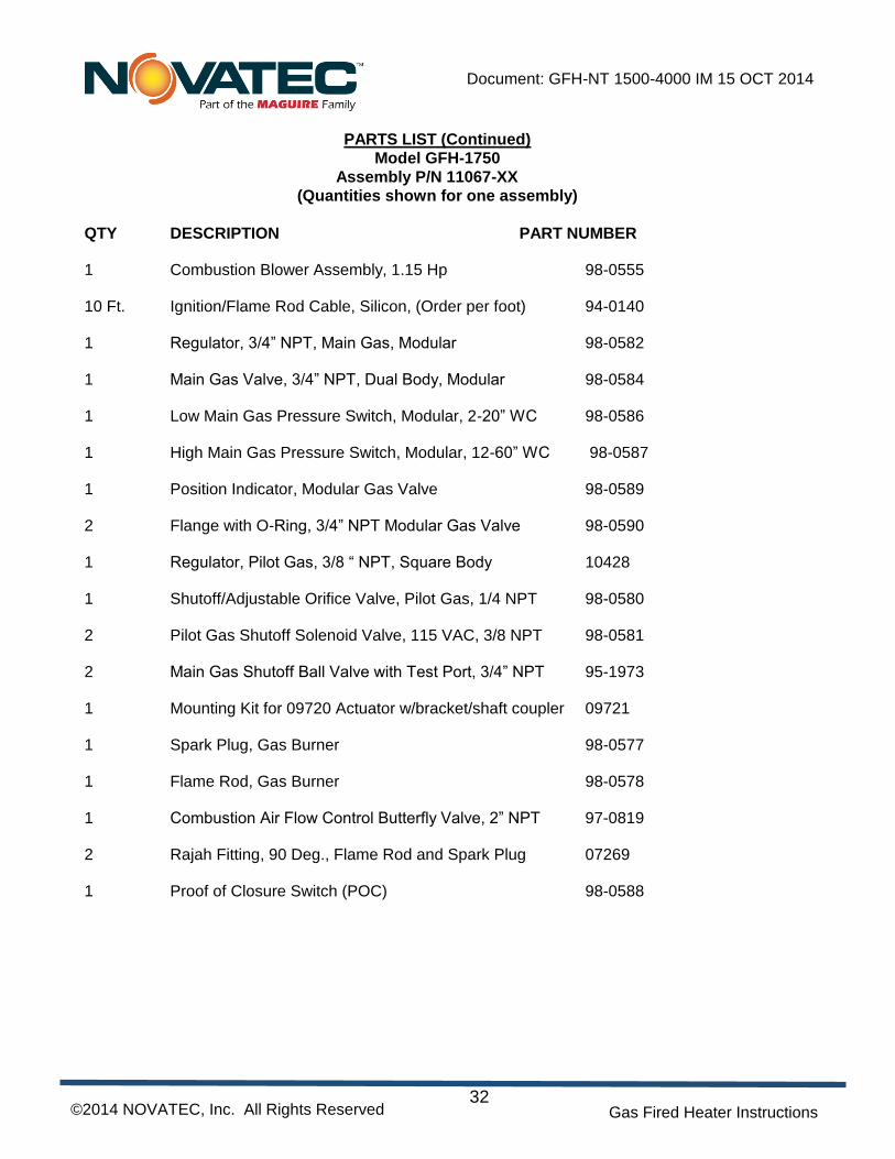
QTY DESCRIPTION PART NUMBER 1 Combustion Blower Assembly, 1.15 Hp 98-0555 10 Ft. Ignition/Flame Rod Cable, Silicon, (Order per foot) 94-0140 1 Regulator, 3/4” NPT, Main Gas, Modular 98-0582 1 Main Gas Valve, 3/4” NPT, Dual Body, Modular 98-0584 1 Low Main Gas Pressure Switch, Modular, 2-20” WC 98-0586 1 High Main Gas Pressure Switch, Modular, 12-60” WC 98-0587 1 Position Indicator, Modular Gas Valve 98-0589 2 Flange with O-Ring, 3/4” NPT Modular Gas Valve 98-0590 1 Regulator, Pilot Gas, 3/8 “ NPT, Square Body 10428 1 Shutoff/Adjustable Orifice Valve, Pilot Gas, 1/4 NPT 98-0580 2 Pilot Gas Shutoff Solenoid Valve, 115 VAC, 3/8 NPT 98-0581 2 Main Gas Shutoff Ball Valve with Test Port, 3/4” NPT 95-1973 1 Mounting Kit for 09720 Actuator w/bracket/shaft coupler 09721 1 Spark Plug, Gas Burner 98-0577 1 Flame Rod, Gas Burner 98-0578 1 Combustion Air Flow Control Butterfly Valve, 2” NPT 97-0819 2 Rajah Fitting, 90 Deg., Flame Rod and Spark Plug 07269 1 Proof of Closure Switch (POC) 98-0588
QTY DESCRIPTION PART NUMBER 1 Combustion Blower Assembly, 1.15 Hp 98-0555 10 Ft. Ignition/Flame Rod Cable, Silicon, (Order per foot) 94-0140 1 Regulator, 1” NPT, Main Gas, Modular 98-0583 1 Main Gas Valve, 1” NPT, Dual Body, Modular 98-0585 1 Low Main Gas Pressure Switch, Modular, 2-20” WC 98-0586 1 High Main Gas Pressure Switch, Modular, 12-60” WC 98-0587 1 Position Indicator, Modular Gas Valve 98-0589 2 Flange with O-Ring, 1” NPT Modular Gas Valve 98-0591 1 Regulator, Pilot Gas, 3/8 “ NPT, Square Body 10428 1 Shutoff/Adjustable Orifice Valve, Pilot Gas, 1/4 NPT 98-0580 2 Pilot Gas Shutoff Solenoid Valve, 115 VAC, 3/8 NPT 98-0581 2 Main Gas Shutoff Ball Valve with Test Port, 1” NPT 07945 1 Mounting Kit for 09720 Actuator w/bracket/shaft coupler 09721 1 Spark Plug, Gas Burner 98-0577 1 Flame Rod, Gas Burner 98-0578 1 Combustion Air Flow Control Butterfly Valve, 2” NPT 97-0819 2 Rajah Fitting, 90 Deg., Flame Rod and Spark Plug 07269 1 Proof of Closure Switch (POC) 98-0588
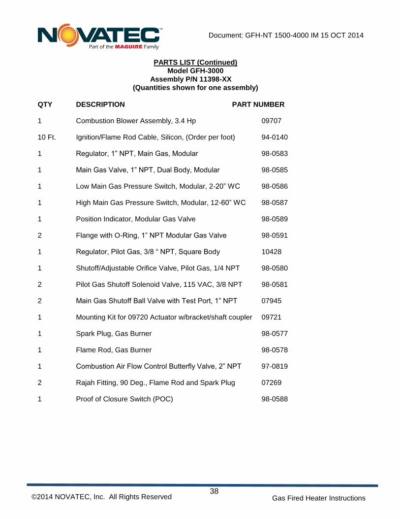
QTY DESCRIPTION PART NUMBER 1 Combustion Blower Assembly, 3.4 Hp 09707 10 Ft. Ignition/Flame Rod Cable, Silicon, (Order per foot) 94-0140 1 Regulator, 1” NPT, Main Gas, Modular 98-0583 1 Main Gas Valve, 1” NPT, Dual Body, Modular 98-0585 1 Low Main Gas Pressure Switch, Modular, 2-20” WC 98-0586 1 High Main Gas Pressure Switch, Modular, 12-60” WC 98-0587 1 Position Indicator, Modular Gas Valve 98-0589 2 Flange with O-Ring, 1” NPT Modular Gas Valve 98-0591 1 Regulator, Pilot Gas, 3/8 “ NPT, Square Body 10428 1 Shutoff/Adjustable Orifice Valve, Pilot Gas, 1/4 NPT 98-0580 2 Pilot Gas Shutoff Solenoid Valve, 115 VAC, 3/8 NPT 98-0581 2 Main Gas Shutoff Ball Valve with Test Port, 1” NPT 07945 1 Mounting Kit for 09720 Actuator w/bracket/shaft coupler 09721 1 Spark Plug, Gas Burner 98-0577 1 Flame Rod, Gas Burner 98-0578 1 Combustion Air Flow Control Butterfly Valve, 2” NPT 97-0819 2 Rajah Fitting, 90 Deg., Flame Rod and Spark Plug 07269 1 Proof of Closure Switch (POC) 98-0588
QTY DESCRIPTION PART NUMBER 1 Combustion Blower Assembly, 3.4 Hp 09707 10 Ft. Ignition/Flame Rod Cable, Silicon, (Order per foot) 94-0140 1 Regulator, 1” NPT, Main Gas, Modular 98-0583 1 Main Gas Valve, 1” NPT, Dual Body, Modular 98-0585 1 Low Main Gas Pressure Switch, Modular, 2-20” WC 98-0586 1 High Main Gas Pressure Switch, Modular, 12-60” WC 98-0587 1 Position Indicator, Modular Gas Valve 98-0589 2 Flange with O-Ring, 1” NPT Modular Gas Valve 98-0591 1 Regulator, Pilot Gas, 3/8 “ NPT, Square Body 10428 1 Shutoff/Adjustable Orifice Valve, Pilot Gas, 1/4 NPT 98-0580 2 Pilot Gas Shutoff Solenoid Valve, 115 VAC, 3/8 NPT 98-0581 2 Main Gas Shutoff Ball Valve with Test Port, 1” NPT 07945 1 Mounting Kit for 09720 Actuator w/bracket/shaft coupler 09721 1 Spark Plug, Gas Burner 98-0577 1 Flame Rod, Gas Burner 98-0578 1 Combustion Air Flow Control Butterfly Valve, 2” NPT 97-0819 2 Rajah Fitting, 90 Deg., Flame Rod and Spark Plug 07269 1 Proof of Closure Switch (POC) 98-0588
QTY DESCRIPTION PART NUMBER 1 Combustion Blower Assembly, 3.4 Hp 09707 10 Ft. Ignition/Flame Rod Cable, Silicon, (Order per foot) 94-0140 1 Regulator, 1” NPT, Main Gas, Modular 98-0583 1 Main Gas Valve, 1” NPT, Dual Body, Modular 98-0585 1 Low Main Gas Pressure Switch, Modular, 2-20” WC 98-0586 1 High Main Gas Pressure Switch, Modular, 12-60” WC 98-0587 1 Position Indicator, Modular Gas Valve 98-0589 2 Flange with O-Ring, 1” NPT Modular Gas Valve 98-0591 1 Regulator, Pilot Gas, 3/8 “ NPT, Square Body 10428 1 Shutoff/Adjustable Orifice Valve, Pilot Gas, 1/4 NPT 98-0580 2 Pilot Gas Shutoff Solenoid Valve, 115 VAC, 3/8 NPT 98-0581 2 Main Gas Shutoff Ball Valve with Test Port, 1” NPT 07945 1 Mounting Kit for 09720 Actuator w/bracket/shaft coupler 09721 1 Spark Plug, Gas Burner 98-0577 1 Flame Rod, Gas Burner 98-0578 1 Combustion Air Flow Control Butterfly Valve, 2” NPT 97-0819 2 Rajah Fitting, 90 Deg., Flame Rod and Spark Plug 07269 1 Proof of Closure Switch (POC) 98-0588
QTY DESCRIPTION PART NUMBER 1 Combustion Blower Assembly, 3.4 Hp 09707 10 Ft. Ignition/Flame Rod Cable, Silicon, (Order per foot) 94-0140 1 Regulator, 1” NPT, Main Gas, Modular 98-0583 1 Main Gas Valve, 1” NPT, Dual Body, Modular 98-0585 1 Low Main Gas Pressure Switch, Modular, 2-20” WC 98-0586 1 High Main Gas Pressure Switch, Modular, 12-60” WC 98-0587 1 Position Indicator, Modular Gas Valve 98-0589 2 Flange with O-Ring, 1” NPT Modular Gas Valve 98-0591 1 Regulator, Pilot Gas, 3/8 “ NPT, Square Body 10428 1 Shutoff/Adjustable Orifice Valve, Pilot Gas, 1/4 NPT 98-0580 2 Pilot Gas Shutoff Solenoid Valve, 115 VAC, 3/8 NPT 98-0581 2 Main Gas Shutoff Ball Valve with Test Port, 1” NPT 07945 1 Mounting Kit for 09720 Actuator w/bracket/shaft coupler 09721 1 Spark Plug, Gas Burner 98-0577 1 Flame Rod, Gas Burner 98-0578 1 Combustion Air Flow Control Butterfly Valve, 2” NPT 97-0819 2 Rajah Fitting, 90 Deg., Flame Rod and Spark Plug 07269 1 Proof of Closure Switch (POC) 98-0588
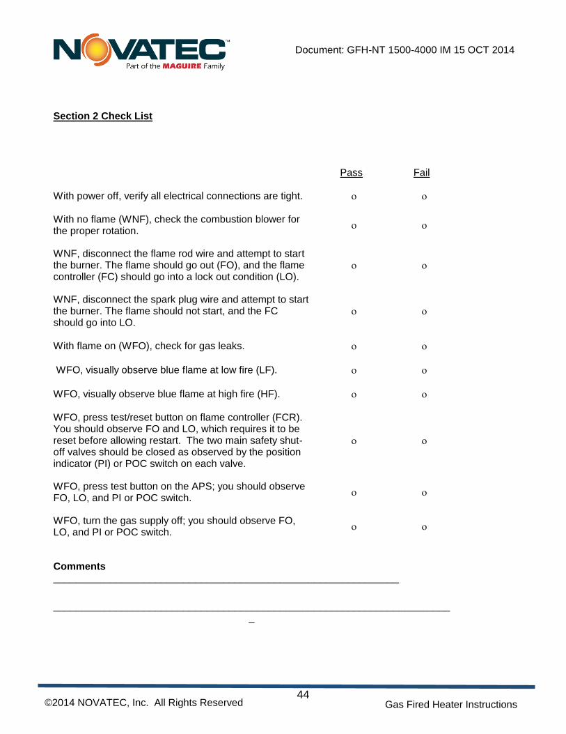
With power off, verify all electrical connections are tight.
With no flame (WNF), check the combustion blower for the proper rotation.
WNF, disconnect the flame rod wire and attempt to start the burner. The flame should go out (FO), and the flame controller (FC) should go into a lock out condition (LO).
WNF, disconnect the spark plug wire and attempt to start the burner. The flame should not start, and the FC should go into LO.
With flame on (WFO), check for gas leaks.
WFO, visually observe blue flame at low fire (LF).
WFO, visually observe blue flame at high fire (HF).
WFO, press test/reset button on flame controller (FCR). You should observe FO and LO, which requires it to be reset before allowing restart. The two main safety shut-off valves should be closed as observed by the position indicator (PI) or POC switch on each valve.
WFO, press test button on the APS; you should observe FO, LO, and PI or POC switch.
WFO, turn the gas supply off; you should observe FO, LO, and PI or POC switch.
16.0 WARRANTY – NOVATEC, INC. - Effective Date 9-28-2011
NOVATEC, INC. offers COMPREHENSIVE PRODUCT WARRANTIES on all of our plastics auxiliary equipment. We warrant each NOVATEC manufactured product to be free from defects in materials and workmanship, under normal use
and service for the periods listed under “Warranty Period”. The obligation of Novatec, under this warranty, is limited to repairing or furnishing, without charge, a similar part to replace any part which fails under normal use due to a material or workmanship defect, within its respective warranty period. It is the purchaser’s responsibility to provide Novatec with immediate written notice of any such suspected defect. Warranted replacement parts are billed and shipped freight pre-paid. The purchaser must return the suspect defective part, freight prepaid and with identifying documentation to receive full credit for the part returned. Novatec shall not be held liable for damages or delay caused by defects. No allowance will be made for repairs or alterations without the written consent or approval of Novatec.
The provisions in equipment specifications are descriptive, unless expressly stated as warranties. The liability of Novatec to the purchaser, except as to title, arising out of the supplying of the said equipment, or its use, whether based upon warranty, contract or negligence, shall not in any case exceed the cost of correcting defects in the equipment as herein provided. All such liability shall terminate upon the expiration of said warranty periods. Novatec shall not in any event be held liable for any special, indirect or consequential damages. Commodities not manufactured by Novatec are warranted and guaranteed to Novatec by the original manufacturer and then only to the extent that Novatec is able to enforce such warranty or guaranty. Novatec, Inc. has not authorized anyone to make any warranty or representation other than the warranty contained here. Non-payment of invoice beyond 90 days will invalidate the warranty. A renewed warranty can be purchased directly from Novatec.
Please note that we always strive to satisfy our customers in whatever manner is deemed most expedient to overcome any issues in connection with our equipment.
Warranty Period: Note: All warranty periods commence with the shipment of the equipment to the customer.
GFH Series Gas Fired Burners = 2 Years
Exclusions: Routine maintenance/replacement parts are excluded from the warranty. These include, but are not
limited to: hoses, desiccant, filters, filter elements, wiper seals, gaskets, dew point sensors, infrared lamps, motors, internal solenoids, fuses and motor brushes. Use with abrasive materials will void the warranty of any standard product. Wear resistant options may be available to extend usable service life with abrasive materials. Novatec reserves the right to limit the warranty if the customer installs replacement parts that do not meet the specifications of the original parts supplied by Novatec.
*Specific Exclusions:
1. NovaDrier warranty is void if coalescing filters are not replaced on a 6-month or yearly basis (per instruction manual) and/or membrane has been exposed to ozone.
2. NovaWheel NW-400 and up Control warranty is 2-years. All other NovaWheel Controls, warranty is 1-year 3. NovaVac Dryer -The ability of the canisters to hold vacuum will be compromised if the vacuum seal edge is damaged from mishandling. We do not warranty canisters damaged from improper handling. We do, however, warranty the seals. 4. LOAD CELLS on our WSB’s are covered by Novatec standard warranty as long as they have not been
damaged from improper handling.
5. Velocity Control Valve warranty is voided if unit is placed in direct material flow.
This warranty shall not apply to equipment: 1. Repaired or altered without written approval of NOVATEC unless such
repair or alteration was, in our judgment, not responsible for the failure 2. Which has been subject to misuse, negligence, accident or incorrect wiring by others 3. Warranty is void if processing rates exceed manufacturer-recommended levels or if damage is caused by
ineffective power isolation and/or power spikes/sags or incorrect installation. Note: All conditions and content of this warranty are subject to change without notice.