INSTRUCTION MANUAL THE MONTAGUE COMPANY 1830 Stearman Avenue P.O. BOX 4954 HAYWARD,CA 94540-4954 TEL: 510/785-8822 FAX: 510/785-3342 Gas Fired Heavy Duty Counter Ranges MONTAGUE Models: C12, C18, C24 & C36 Keep area around appliances free and clear from combustibles. PLEASE RETAIN THIS MANUAL FOR FUTURE REFERENCE. These instructions should be read thoroughly before attempting installation. Set up and installation should be performed by qualified installation personnel. Effective October 1, 2001: All Montague heavy duty ranges and broilers will be built with orifices and regulators set to operate on 6” W.C. manifold pressure You must specify the manifold pressure and gas type listed on the model identifi- cation plate to order replacement burner valves, orifices, or pressure regulators.
Transcript
INSTRUCTION MANUAL
THE MONTAGUE COMPANY 1830 Stearman Avenue P.O. BOX 4954
HAYWARD,CA 94540-4954
TEL: 510/785-8822 FAX: 510/785-3342
Gas Fired Heavy Duty Counter Ranges
MONTAGUE
Models: C12, C18, C24 & C36
Keep area around appliances free and clear from combustibles.
PLEASE RETAIN THIS MANUAL FOR FUTURE REFERENCE.
These instructions should be read thoroughly before attempting installation. Set up and installation should be performed by qualified installation personnel.
Effective October 1, 2001: All Montague heavy duty ranges and broilers will be built with orifices and regulators set to operate on 6” W.C. manifold pressure
You must specify the manifold pressure and gas type listed on the model identifi-cation plate to order replacement burner valves, orifices, or pressure regulators.
2
IMPORTANT
INSTRUCTIONS TO BE FOLLOWED IN THE EVENT THE USER SMELLS GAS MUST BE POSTED IN A PROMINENT LOCATION. THIS INFORMATION MAY BE OBTAINED BY CONSULTING THE LOCAL GAS SUPPLIER.
SHIPPING DAMAGE CLAIM PROCEDURE For your protection, please note that equipment in this shipment was carefully inspected and packed by skilled personnel before leaving the factory. The transportation company assumes full responsibility for safe delivery upon acceptance of this shipment. If shipment arrives damaged: 1. VISIBLE LOSS OR DAMAGE—Be certain this is noted on freight bill or express receipt,
and signed by person making delivery. 2. FILE CLAIM FOR DAMAGES IMMEDIATELY—Regardless of the extent of damage. 3. CONCEALED LOSS OR DAMAGE—If damage is unnoticed until merchandise is un-
packed, notify transportation company or carrier immediately, and file “concealed dam-age” claim with them. This should be done within fifteen (15) days of date that delivery was made to you. Be sure to retain container for inspection.
We cannot assume responsibility for damage incurred in transit. We will, however, be glad to furnish you with necessary documents to support your claim.
WARNING: Improper installation, adjustment, alteration, service or maintenance can cause property damage, injury or death. Read the operating and maintenance instructions thor-oughly before installing or servic-ing this equipment.
FOR YOUR SAFETY:
Do not store or use gasoline or other flammable vapors and liquids in the vicinity of this or any other appliance.
The MONTAGUE gas ranges manufactured for use with the type of gas indicated on the name-plate. The Montage heavy duty gas counter ranges are produced with the best possible materials and workmanship. PROPER INSTALLATION IS ESSENTIAL FOR SAFE AND EFFICIENT TROU-BLE-FREE OPERATION.
Qualified installation personnel are individuals, a firm, corporation, or company which either in person or through a representative are engaged in, and are responsible for: A. The installation or replacement of gas piping or the connection, installation, repair or servicing
of equipment, who is experienced in such work, familiar with all precautions required, and has complied with all requirements of state or local authorities having jurisdiction. Reference: Na-tional Fuel Gas Code Z223.1
Ventilating Hood The range(s) must be installed under a properly designed ventilating hood. The hood should extend at least 6” beyond all sides of the unit. The hood should be connected to an adequate mechanical exhaust system.
THE INSTALLATION INSTRUCTIONS CONTAINED HEREIN ARE FOR THE USE OF QUALIFIED INSTALLAION AND SERVICE PERSONNEL ONLY. INSTALLATION OR SERVICE BY OTHER THAN QUALIFIED PERSONNEL MAY RESULT IN DAMAGE TO THE BR/INJURY TO THE OPERATOR.
READ CAREFULLY AND FOLLOW THESE INSTRUCTIONS
THE RANGE(S) MUST BE INSTALLED IN ACCORDANCE WITH THE LOCAL CODES, OR IN THE ABSENCE OF LOCAL CODES, WITH THE NATIONAL FUEL GAS CODE, ANSI Z223.1, INCLUDING: 1. The appliance and its individual shutoff valve must be disconnected from the
gas supply piping system during any pressure testing of that system at test pressures in excess of 1/2 psig. (3.45 kPa).
2. The appliance must be isolated from the gas supply piping system by closing its
individual manual shutoff valve during any pressure testing of the gas supply piping system at test pressure equal to or less than 1/2 psig. (3.45 kPa).
PROVISIONS MUST BE MADE FOR ADEQUATE AIR SUPPLY TO THE UNIT.
4
Information on the construction and installation of ventilating hoods may be obtained from the “Standard for the Installation of Equipment for the Removal of Smoke and Grease Laden Vapors from Commercial Cooking Equipment”, NFPA No. 96, available from the National Fire Protection Association, Batterymarch Park, Quincy, MA 02269. It is also necessary that the sufficient room air ingress be allowed to compensate for the amount of air removed by the ventilation system. Otherwise, a subnormal atmospheric pressure will occur which may interfere with burner performance or may extinguish the pilot flame. In case of unsatisfactory oven performance, check with the exhaust fan in the “OFF” position.
Clearances Adequate clearances must be provided in the aisle and at the side and back to allow for servicea-bility. Adequate clearance for air openings into the combustion chamber must be provided.
ASSEMBLY: Uncrate range as near to final location as possible. Remove all shipping wire from burners and all packing material and accessories from unit. Then assemble as follow: 1. When legs are provided, screw the adjustable feet of the legs in all the way. Then tightly screw
the complete leg assembly into the mounting holes at each corner of the range. 2. If top castings are removed, identify castings to they are replaced in the same position and on
the same range as when received from the factory.
INSTALLATION
CLEARANCES COMBUSTIBLE NONCOMBUSTIBLE CONSTRUCTION CONSTRUCTION BACK: 2” 0” LEFT & RIGHT SIDE: *6” 0” WITH 4” OR 6” LEGS: SUITABLE FOR INSTALLATION ON COMBUSTIBLE FLOORS. WITHOUT LEGS: FOR USE ONLY ON NONCOMBUSTIBLE FLOORS.
CAUTION! DO NOT OBSTRUCT THE FLOW OF COMBUSTION AND VENTILATION AIR TO THE
RANGE(S). KEEP THE APPLIANCE AREA FREE AND CLEAR FROM COMBUSTIBLES.
INSTALLATION
5
INSTALLATION
Setting in Place Battery Arrangements 1. Place the first range in the exact position it will occupy in the battery. 2. Using a carpenter’s level, level the unit from front to rear and side to side. Adjust as follows: 4” ADJUSTABLE LEGS: Adjust by turning foot on adjustable legs. WITHOUT LEGS: Place shim under the low side. This operation is important since variations in floors and curbs are common. Unless units are level, difficulty will be encountered in a aligning the gas supply manifold and the units will not butt together tightly. 3. Remove the upper valve panel from the range. 4. Move the next range into position. 5. Engage union nut on manifold with male fitting on next unit and draw up union nut hand tight. Be
sure appliances butt together both front and rear. If manifolds do not align, then ranges are not level. In extreme cases, it may be necessary to loosen manifold bolts and adjust.
6. Continue leveling and connecting gas supply manifolds together until all appliances in the
battery are connected. 7. Tighten manifold union gas tight. Use back up wrench to prevent manifold from rotating. FAILURE TO DO THIS MAY RESULT IN DAMAGE TO PILOTS AND GAS VALVES. C CHECK ENTIRE SYSTEM FOR GAS LEAKS.
Fry Top Ranges: Fry Top Plate Adjustment: Leveling bolts are at the rear of the range under the fry top plate. Adjust leveling bolts so that plate is pitched to the front to provide for grease runoff. (See Fig. 1) High Shelf, High Back or Stub Back: Lift high shelf, high back or stub back above the range and slide legs into position. (See Fig. 2)
6
INSTALLATION
GAS APPLIANCE REGULATOR Unless otherwise specified, the range is equipped with fixed orifices for use with a manifold pressure of 4.0 or 6.0” water column for natural gas and 10.0” water column for propane gas. (Note: See rat-ing plate for manifold pressure.) The gas pressure regulator furnished by the installer must comply with the following: 1. The pressure regulator(s) must have a maximum regulation capacity for the total connected load. 2. The pressure regulator(s) installed must be listed by a nationally recognized testing agency. 3. The pressure regulator(s) must have a pressure adjustment range to allow adjustment to the
manifold pressure on the appliance rating plate. 4. Unless the manifold pressure on all connected appliances is the same, a separate pressure reg-
ulator must be supplied for each appliance(s) having different manifold pressures.
A GAS APPLIANCE PRESSURE REGULATOR SUITABLE FOR THE BATTERY APPLICATION AND ADJUSTED FOR THE MANIFOLD PRESSURE SPECIFIED ON THE RANGE NAMEPLATE MUST BE FURNISHED BY THE INSTALLER AT THE TIME OF INSTALLATION.
7
INSTALLATION
GAS CONNECTION Before connecting the range battery to the gas supply line, be sure that all new piping has been cleaned and purged to prevent any foreign matter from being carried into the controls by the gas. In some cases, filters or drops are recommended. A separate Gas Shut Off Valve must be in-stalled upstream, from the gas pressure regulator adjacent to the range battery and located in an accessible area.
It is important that adequately sized piping be run directly to the point of connection at range bat-tery with as few elbows and tees as possible. Consult local gas company for proper piping size and gas pressure.
Turn Gas Shut Off Valve “ON” and immediately check carefully for gas leaks. Do this before at-tempting to operate the range battery. PILOT ADJUSTMENT—TOP BURNERS OPEN TOP: The front and rear pilots are controlled by one valve. To adjust pilot, turn adjusting screw counter-clockwise to increase or clockwise to decrease the pilot flame. Adjust flem to a point where only a trace of yellow tip remains. HOT TOP & FRYTOP: Each pilot is controlled by a pilot valve. Turn adjusting screw until pilot flame is 1/2” high.
WARNING: CAP ALL UNUSED OPEN ENDS OF THE GAS SUPPLY MANIFOLD.
PIPE JOINT COMPOUND OR THREAD SEALANT THAT IS USED SHOULD BE RESISTANT TO ACTION OF LIQUEFIED PETROLEUM GASES.
TEST ALL PIPE JOINTS FOR LEAKS BEFORE OPERATING RANGE(S). THIS INCLUDES ALL GAS CONNECTIONS THAT MAY HAVE LOOSENED DURING
SHIPMENT. USE A RICH SOAP SOLUTION (OR OTHER ACCEPTED LEAK TESTER) AROUND ALL PIPE CONNECTIONS AND ALL OTHER JOINTS. DO NOT USE AN
OPEN FLAME. ABSOLUTELY NO LEAKAGE SHOULD OCCUR, OTHERWISE THRE IS A DANGER OF FIRE OR EXPLOSION DEPENDING UPON CONDITIONS. NEVER USE
IF LEAKAGE IS DETECETD.
8
BURNER ADJUSTMENT The efficiency of the range depends on a delicate balance between the supply of air and volume of gas so that complete combustion is achieved. Whenever this balance is disturbed, poor operating characteristics occur. The air supply is controlled by an air shutter on the front of the burner. The air shutter openings should be increased until the flame on the burner begins to “lift”. The air shutter should then be closed slightly and locked in place. A yellow streaming flame indicates insufficient air. This condition can be corrected by increasing the air shutter opening. FRY TOP THERMOSTATS The bypass (minimum burner flame) has been adjusted at factory and should require no further ad-justment if the gas manifold pressure is correct.
INSTALLATION
THE BYPASS FLAME MUST BE RECHECKED WHEN PERFORMING CHECKOUT OF RANGE PRIOR TO PLACING EQUIPMENT IN SERVICE. THE BYPASS MUST BE SET CAREFULLY AND ACCURATELY. REFER TO SERVICE SECTION OF THIS MANUAL FOR PROPER PROCEDURE.
9
OPERATION
GAS CONTROLS TOP BURNERS– OPEN, HOT TOP, AND MANUAL FRY TOP Check that pilots are burning. Then rotate valve handles counter clockwise to full on, burner will ignite automatically. Adjust flame height as desired. To shut down, rotate valve handle clockwise to “OFF” position. FRY TOP—THERMOSTAT CONTROLLED Check that pilot(s) are burning. Then push thermostat dial inward and rotate dial counter-clockwise to maximum thermostat setting, burner will ignite automatically. After ignition, turn ther-mostat dial to desired setting. To shut down, rotate thermostat dial clockwise to “OFF” position. SUGGESTIONS * Break the habit of turning on all your equipment first thing every morning. Unless you plan to use a piece of equipment, leave it off until it’s needed. * There is no need to preheat an open top burner. Use full flame to start foods cooking quickly; reduce flame to simmer foods. Regulate the burners so that flame tips touch the bottom of the utensil. Use lids on pots to keep heat in. Turn burner off when not in use. * Limit preheat time to 10-15 minutes on hot top ranges using full flame. Use flat bottom pans for efficient use of heat. Use lids to keep heat in. During idling period, use low flame or turn one or more burners off. Heat only section of hot top required. * Preheat fry top 10-15 minutes prior to use. Usually, a medium or low flame is adequate for light frying. If fry top has a thermostat, use it to avoid wasting gas and for best results. During slack periods, turn the burner down.
OPERATING INFORMATION FOR THIS RANGE HAS BEEN PREPARED FOR USE BY QUALIFIED AND/OR PROFESSIONAL OPERATING PERSONNEL.
CAUTION DO NOT OBSTRUCT THE FLOW OF COMBUSTION AND VENTILATION AIR TO THE RANGE. KEEP THE APPLIANCE AREA FREE AND CLEAR FROM COMBUSTIBLES.
IN THE EVENT A GAS ODOR IS DETECTED, SHUT DOWN UNITS AT MAIN SHUT OFF VALVE AND CONTACT THE LOCAL GAS COMPANY OR GAS SUPPLIER FOR
SERVICE
10
MAINTENANCE
Care and Cleaning The complete range should be given a periodic cleaning. Lint and grease suspended in the air tend to collect in air passages. Therefore, all flueways, air passages and openings, burner ports, primary air openings, etc. should be periodically cleaned to prevent clogging. Exterior PAINTED SURFACE: Allow equipment to cool after use and wash with a mild detergent or soap solution. Dry thoroughly with a dry cloth. STAINLESS STEEL SURFACES: To remove dirt, grease, or product residue from stainless steel, use ordinary soap and water (with or without detergent) applied with a sponge or cloth. Dry thor-oughly with a clean cloth.
To remove grease and food platter, or condensed vapors that have baked on the equipment, ap-ply cleanser to a damp cloth or sponge and rub cleanser on the metal in the direction of the pol-ishing lines on the metal. Rubbing cleanser as gently as possible in the direction of the polished lines will not mar the finish of the stainless steel. NEVER RUB WITH A CIRCULAR MOTION. Soil and burnt deposits which do not respond to the above procedure can usually be removed by rubbing the surface with SCOTCH-BRITE scouring pads or STAINLESS scouring pads. DO NOT USE ORDINARY STEEL WOOL as any particles left on the surface will rust and further spoil the appearance of the finish. NEVER USE A WIRE BRUSH, STEEL SCOURING PADS (EXCEPT STAINLESS), SCRAPER, FILE, OR OTHER STEEL TOOLS. Surfaces which are marred collect dirt more rapidly and become more difficult to clean. Marring also increases the possibility of cor-rosive attack. To remove heat tint: Darkened areas sometimes appear on stainless steel surfaces where the area has been subjected to excessive heat. These darkened areas are caused by thickening of the protective surface of the stainless steel and are not harmful. Heat tint can normally be re-moved by the foregoing, but tint which does not respond to this procedure calls for a vigorous scouring in the direction of the polish lines, using SCOTCH-BRITE scouring pads or a STAIN-LESS scouring pad in combination with a powdered cleanser. Heat tint action may be lessened by not applying or reducing heat to equipment during slack periods. OPEN TOP SECTION DAILY: Wipe top with burlap or other grease absorbing material to remove spillovers, grease, etc. before they burn in. WEEKLY: Open Top Section should be washed in a solution of washing soda and water (after they are entirely cooled). Remove and wash drip pan under burners. Brush burner head weekly with a stiff wire brush and clean clogged ports with stiff fire or ice pick. Excessive grease build up may be removed from burners by soaking in a solution of washing soda. Dry Burners by inverting on oven rack in a low temperature oven.
11
HOT TOP SECTION DAILY: Wipe top with heavy burlap or steel wool, rub briskly until clean. Lift rings and plates to clean all flanges under lid. NEVER POUR WATER ON A HOT TOP SECTION. FRY TOP SECTION DAILY: Use flat edge of spatula or metal scraper to keep surface free of encrusted material during use, wipe frequently with heavy absorbent cloth. After griddle is cooled, polish with soft griddle stone or a good grade grill pad. DO NOT SCRATCH. The griddle may be washed with warm water and a cleanser. Water will not crack this griddle plate. To oil the griddle, use hydrogenated shortening. Never use salad oils, margarine or butter, as these shortenings cannot withstand temperatures greater than 300°F.
MAINTENANCE MAINTENANCE
12
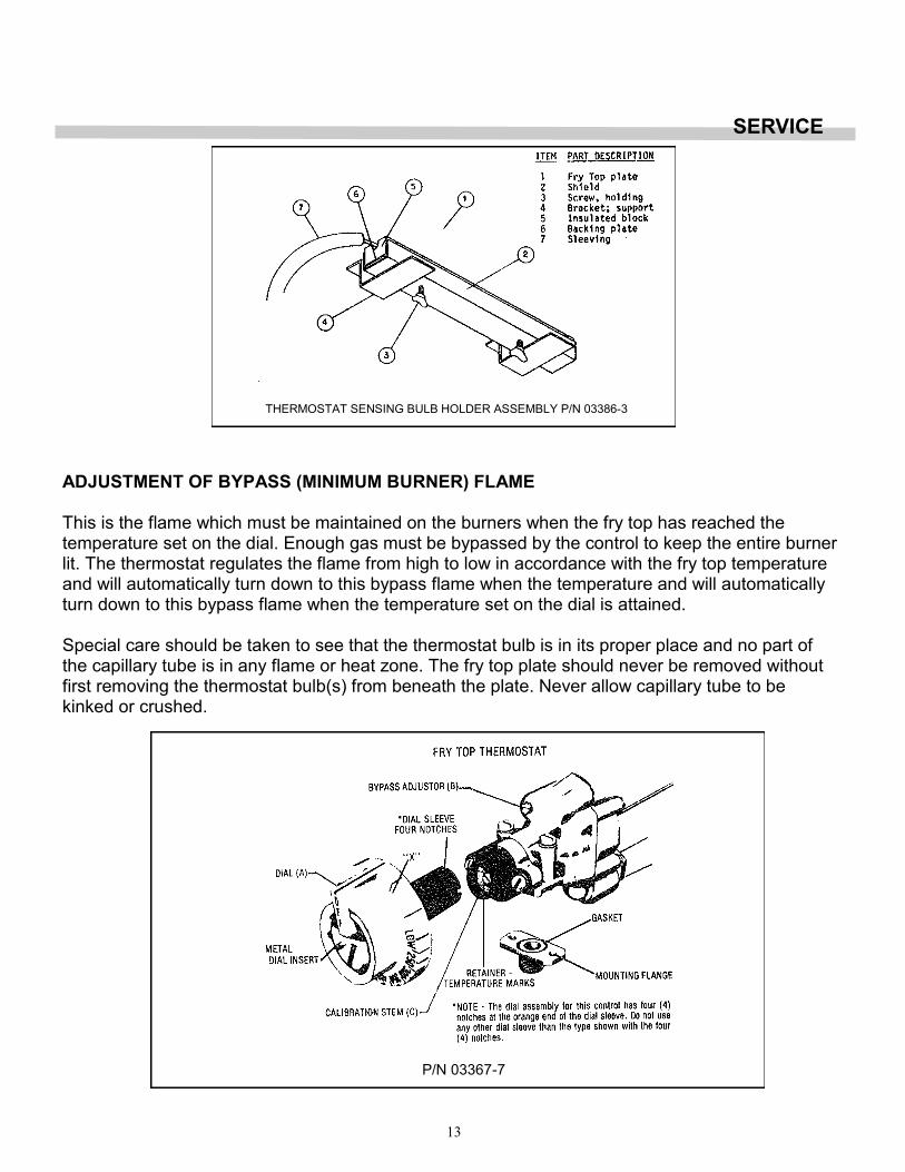
FRY TOP THERMOSTAT The Model BJ Robertshaw is a combination thermostat and gas valve. The gas is turned on and the temperature setting made by a single rotation of the dial. This valve automatically locks itself in the OFF position. To use, push dial inward, rotate counter-clockwise to the desired temperature. To shut gas off, rotate clockwise to OFF position. This thermostat is a precision instrument carefully made and properly calibrated (i.e. the dial is properly set) at the factory to control temperatures accurately. It should control temperatures for the proper cooking of food without recalibration. The calibration of this thermostat should not be changed until considerable experience with cooking results has definitely proved that the thermo-stat is not maintaining the proper temperature. THERMOSTAT INSTALLATION With front of griddle plate raised, slide the thermostat bulb assembly into the support brackets at-tached to the underside of the fry top plate. Tighten the two holding screws. The excess capillary tube should be pulled forward and down as low as possible out of the heat zone, so that there is no chance of it coming in contact with the burner flame. Push the sleeving up against the bulb holder. A loose fit between the bulb holder and plate may damage the thermostat so that it will fit between the bulb holder and plate may damage the thermostat so that it will not control the temperature of the fry top plate.
SERVICE
WHEN SERVICE IS NEEDED, CONTACT A LOCAL SERVICE COMPANY, DEALER, OR FACTORY TO PERFORM MECHANICAL MAINTENANCE AND REPAIRS. THESE INSTRUCTIONS ARE INTENDED FOR USE BY A COMPETENT SERVICE PERSONNEL.
CAUTION: TURN OFF GAS SUPPLY WHEN SERVICING GAS CONTROL SYSTEM.
CAUTION: THE RECALIBRATION SHOULD NOT BE MADE UNTIL THE BYPASS (MINIMUM BURNER) FLAME HAS BEEN PROPERLY ADJUSTED.
13
ADJUSTMENT OF BYPASS (MINIMUM BURNER) FLAME This is the flame which must be maintained on the burners when the fry top has reached the temperature set on the dial. Enough gas must be bypassed by the control to keep the entire burner lit. The thermostat regulates the flame from high to low in accordance with the fry top temperature and will automatically turn down to this bypass flame when the temperature and will automatically turn down to this bypass flame when the temperature set on the dial is attained. Special care should be taken to see that the thermostat bulb is in its proper place and no part of the capillary tube is in any flame or heat zone. The fry top plate should never be removed without first removing the thermostat bulb(s) from beneath the plate. Never allow capillary tube to be kinked or crushed.
THE BYPASS MUST BE SET CAREFULLY AND ACCURATELY AS FOLLOWS: 1. Light burners and turn Dial (A) counterclockwise and to a point midway between the “Gas On”
mark and the next graduation to the right of it (shown by “X”). If the burner goes out entirely, the bypass is closed
2. Slip off Dial (A). Remove the valve panel from the front of the range. 3. With a screwdriver, turn bypass adjuster (B), Turning it in clockwise decreases the bypass
flame. Adjust until there is a flame approximately 1/8” high over the entire burner. 4. Replace dial, rotating dial clockwise until it snaps into its original position. 5. Reinstall the valve panel on front of the range. FRY TOP THERMOSTAT CALIBRATION CHECK: The fry top temperature should be checked or recalibrated with the fry top hot. NOTE: See “Adjustment of Bypass (Minimum Burner) Flame” before recalibrating this thermostat. HOT CHECK METHOD: 1. Place reliable thermometer in center of the top of the fry top over the thermal bulb. 2. Set Dial (A) to 350°F. 3. Wait until temperature rises and remains constant. 4. If dial does not agree with thermometer readings, slip off Dial (A) and push out metal insert. 5. Replace dial, turn to 350° mark. 6. Hold dial firmly, insert screwdriver through center of dial and push calibration stem ( C ) inward.
DO NOT TURN THIS STEM. 7. While holding calibration stem (C ) in firmly with screwdriver, turn dial until it is at the actual fry
top temperature as shown by the thermometer. Release pressure on calibration stem. Replace dial insert.
SERVICE
15
SERVICE
ORIFICE SIZE CHART DRILL SIZE
Type of Burn-er
A B C D Open Top
20,000
D Open Top
30,000 Front Rear
F
Natural Gas 4.0” W.C.
50 46 35 45 37
45 50 45
Natural Gas 6.0” W.C.
48 42 45 52
Propane Gas 10.0” WC
56 55 50 55 55 56 55
D 1/2 Hot Top
16
17
18
19
20
The State of California enacted the California Safe Drinking Water and Toxic Enforcement Act of 1986, (Prop. 65), which "prohibits any person in the course of doing business from knowingly and intentionally exposing any individ-ual to a chemical known to the State of California to cause cancer or reproductive toxicity without first giving clear and reasonable warning to such individuals." The Governor's Scientific Advisory Panel added carbon monoxide to the list of hazardous chemicals known to cause reproductive harm. In order to establish full compliance with Proposition 65, we attached a yellow warning label to each gas fired unit manufactured by the Montague Company. Carbon monoxide would not be present in concentrations that would pose a "significant risk" to the consumer when the equipment is installed, operated and maintained as follows: 1. Installed in accordance with all local codes, or in the absence of local codes, with the current National Fuel Gas Code Z223.1. 2. Installed under a properly designed and operating exhaust hood. 3. Connected to the type of gas for which the unit is equipped. 4. Proper appliance pressure regulator installed on the gas supply line and adjusted for the manifold pressure marked on the rating plate. 5. Adequate air supply to the unit. 6. The equipment is operated in the manner intended using the proper utensil for that type of appliance. 7. Keep the equipment clean and have it checked periodically. 8. Burner air adjustments, mechanical maintenance and repairs should be performed by qualified service personnel. If the equipment is not installed, operated and maintained in accordance with the above, concentrations of carbon monoxide in excess of the established limits could present in the kitchen environment. ALL PERSONNEL IN THE WORKPLACE WHO MAY BE SUBJECT TO ANY EXPOSURE OF CARBON MONOXIDE MUST BE WARNED OF SUCH POSSIBLE EXPOSURE. THIS WARNING SHOULD BE CONVEYED IN A MANNER SO THAT IT IS CLEARLY UNDERSTOOD BY THE EMPLOYEE, AND THE EMPLOYEE SHOULD BE ASKED IF IN FACT HE OR SHE UNDERSTANDS THE CORRECT METHOD OF OPERATION OF THE EQUIPMENT AND THAT A RISK OF EXPOSURE EXISTS IF THE EQUIPMENT IS OPERATED IMPROPERLY.
WARNING If not installed, operated and maintained in accordance with the manufacturer's instructions, this product could expose you to substances in fuel or in fuel combustion which can cause death or serious illness and which are known to the State of California to cause cancer, birth defects or other reproductive harm.
The MONTAGUE COMPANY 1830 Stearman Avenue, P.O. Box 4954 Hayward, CA 94540-4954
The MONTAGUE COMPANY 1830 Stearman Avenue, P.O. Box 4954 Hayward, CA 94540-4954
21
IMPORTANT
Copy the following information from the rating plate for your records:
Model No. _____________________________________________
Serial No. _____________________________________________