500 Tennessee Waltz Parkway Ashland City, TN 37015 www.statewaterheaters.com PLACE THESE INSTRUCTIONS ADJACENT TO HEATER AND NOTIFY OWNER TO KEEP FOR FUTURE REFERENCE. PRINTED IN U.S.A. 1005 PART NO. 197242-000 SUPERSEDES PART NO. 196758-000 Rooftop Water Heater Model SRT80 120NE COMMERCIAL GAS WATER HEATER GAS-FIRED POWER BURNER FOR DOMESTIC HOT WATER CAUTION TEXT PRINTED OR OUTLINED IN RED CONTAINS INFORMATION RELATIVE TO YOUR SAFETY. PLEASE READ THOROUGHL Y BEFORE INST ALLING AND USING THIS APPLIANCE. • INSTALLATION • OPERATION • SERVICE • MAINTENANCE • LIMITED WARRANTY Thank you for buying this energy efficient water heater from State Industries. We appreciate your confidence in our products. WARNING: If the information in these instructions is not followed exactly, a fire or explosion may result causing property damage, personal injury or death. – Do not store or use gasoline or other flammable vapors and liquids in the vicinity of this or any other appliance. – WHAT TO DO IF YOU SMELL GAS: • Do not try to light any appliance. • Do not touch any electrical switch; do not use any phone in your building. • Immediately call your gas supplier from a neighbor's phone. Follow the gas supplier's instructions. • If you cannot reach your gas supplier, call the fire department. – Installation and service must be performed by a qualified installer, service agency or the gas supplier.
Transcript
1
500 Tennessee Waltz ParkwayAshland City, TN 37015
www.statewaterheaters.com
PLACE THESE INSTRUCTIONS ADJACENT TO HEATER ANDNOTIFY OWNER TO KEEP FOR FUTURE REFERENCE.
PRINTED IN U.S.A. 1005 PART NO. 197242-000SUPERSEDES PART NO. 196758-000
Rooftop Water Heater Model SRT80 120NECOMMERCIAL GAS WATER HEATER
GAS-FIRED POWER BURNERFOR DOMESTIC HOT WATER
CAUTIONTEXT PRINTED OR OUTLINED IN RED CONTAINSINFORMATION RELATIVE TO YOUR SAFETY. PLEASEREAD THOROUGHLY BEFORE INSTALLING AND USINGTHIS APPLIANCE.
Thank you for buying this energy efficient water heater fromState Industries. We appreciate your confidence in ourproducts.
WARNING: If the information in theseinstructions is not followed exactly, a fireor explosion may result causing propertydamage, personal injury or death.
– Do not store or use gasoline or otherflammable vapors and liquids in thevicinity of this or any other appliance.
– WHAT TO DO IF YOU SMELL GAS:
• Do not try to light any appliance.• Do not touch any electrical switch;
do not use any phone in yourbuilding.
• Immediately call your gas supplierfrom a neighbor's phone. Follow thegas supplier's instructions.
• If you cannot reach your gas supplier,call the fire department.
– Installation and service must beperformed by a qualified installer,service agency or the gas supplier.
2
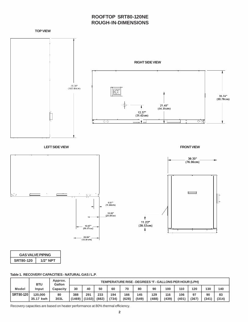
ROOFTOP SRT80-120NEROUGH-IN-DIMENSIONS
GAS VALVE PIPINGSRT80-120 1/2" NPT
Recovery capacities are based on heater performance at 80% thermal efficiency.
TEMPERATURE RISE - DEGREES °F - GALLONS PER HOUR (LPH)
FRONT VIEW
TOP VIEW
LEFT SIDE VIEW
RIGHT SIDE VIEW
3
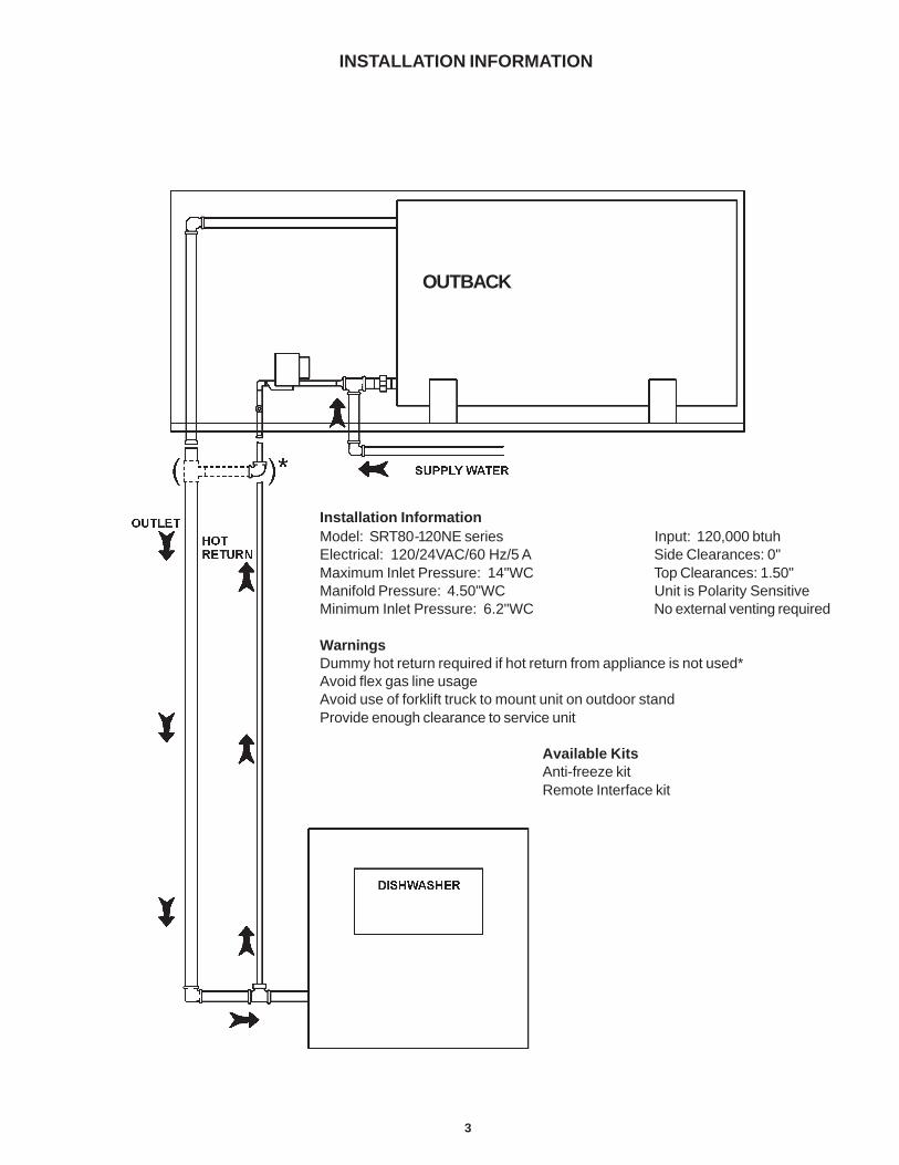
INSTALLATION INFORMATION
Installation InformationModel: SRT80-120NE series Input: 120,000 btuhElectrical: 120/24VAC/60 Hz/5 A Side Clearances: 0"Maximum Inlet Pressure: 14"WC Top Clearances: 1.50"Manifold Pressure: 4.50"WC Unit is Polarity SensitiveMinimum Inlet Pressure: 6.2"WC No external venting required
WarningsDummy hot return required if hot return from appliance is not used*Avoid flex gas line usageAvoid use of forklift truck to mount unit on outdoor standProvide enough clearance to service unit
Available KitsAnti-freeze kitRemote Interface kit
OUTBACK
4
This design complies with the current edition of ANSI Z21.10.3 asan automatic circulating tank type water heater and automaticstorage water heater.
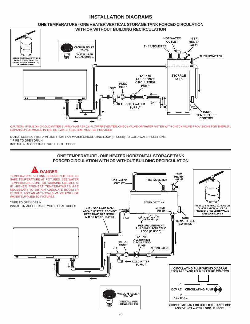
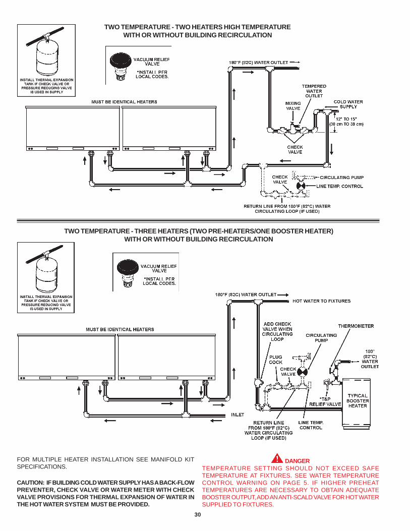
Detailed installation diagrams are found in this manual. Thesediagrams will serve to provide the installer with a reference for thematerials and methods of piping necessary. It is highly essentialthat all water, gas piping and wiring be installed as shown on thediagrams.
Particular attention should be given to the installation ofthermometers at the locations indicated on the diagrams as theseare necessary for checking the proper functioning of the heater.
In addition to these inst ruct ions, the equipment shall beinstalled in accordance with all local codes. The authorityhaving jurisdiction should be consulted before installing.
In the absence of local codes, the installation must complywith the current editions of the National Fuel Gas Code,ANSI Z223.1/NFPA 54 and the National Electric Code, NFPA 70.The former is avai lable from the Canadian StandardsAssociation, 8501 East Pleasant Valley Road, Cleveland, OH44131, and both documents are available from the NationalFire Protection Association, 1 Batterymarch Park, Quincy, MA02269.
AIR SYSTEM ASSEMBLY .................................................................. 7Blower Assembly .......................................................................... 7Blower Plenum .............................................................................. 7Air Hose ........................................................................................ 8Flue Adapter .................................................................................. 8Exhaust Vent ................................................................................. 8
CONTROL SYSTEM ........................................................................... 8Blocked Outlet Switch .................................................................. 8Blocked Inlet/Prover Switch .......................................................... 8Low Gas Pressure Switch ........................................................... 9On/Off Switch ............................................................................... 9Hot Surface Igniter ........................................................................ 9OIM - Outdoor Interface Module ................................................... 9WR Ignition Control Board ............................................................. 9Low Water Cutoff Board and Probe ............................................ 10Thermostat/E.C.O. Probes ............................................................ 10Transformer .................................................................................. 10Junction Box ................................................................................. 10
TANK ASSEMBLY SYSTEM .............................................................. 10Tank Insulation ............................................................................... 10
INSTALLATION INSTRUCTIONS ......................................................... 11Required Ability ............................................................................. 11Insulation Blankets ........................................................................ 11Locating The Heater ...................................................................... 11-12Provide Unit Support ..................................................................... 12Roof Curb ...................................................................................... 12-13Rig and Place Unit ......................................................................... 13Outdoor Stand ............................................................................... 14Clearances .................................................................................... 14Hard Water .................................................................................... 14Air Requirements .......................................................................... 14
FOREWORD
TABLE OF CONTENTS
Chemical Vapor Corrosion ............................................................ 14VENTING ............................................................................................ 15
Vent Terminals ............................................................................... 15Pressure Switches ....................................................................... 15Gas Piping ..................................................................................... 15-16Connection of Gas Pipe ................................................................ 16Purging .......................................................................................... 16Gas Meter Size - City Gases Only ............................................... 16Gas Pressure Regulation .............................................................. 16Gas Valves .................................................................................... 17
SYSTEM CONNECTIONS ................................................................... 17Thermometers ............................................................................... 17Relief Valve ................................................................................... 17Water Line Connections ............................................................... 17Closed System .............................................................................. 17Water (Potable) Heating and Space Heating ................................ 17Water Heater Wiring ...................................................................... 17-18
INSTALLATION DIAGRAMS ............................................................... 28-32CHECKLIST AND SERVICE INFORMATION ........................................ 33TROUBLE-SHOOTING ........................................................................ 33-34REPLACEMENT PARTS ...................................................................... 34LIMITED WARRANTY ......................................................................... 35
PAGE PAGE
5
Figure 1 shows the approximate time-to-burn relationship fornormal adult skin. Short repeated heating cycles caused by smallhot water uses can cause temperatures at the point of use toexceed the thermostat setting by up to 20°F/-11°C. If you experiencethis type of use, you should consider using lower temperaturesettings to reduce scald hazards.
Temperature Time to Produce 2nd & 3rdSetting Degree Burns on Adult Skin
180°F / 82°C Nearly instantaneous
170°F / 77°C Nearly instantaneous
160°F / 71°C About 1/2 second
150°F / 66°C About 1-1/2 seconds
140°F / 60°C Less than 5 seconds
130°F / 54°C About 30 seconds
120°F / 49°C More than 5 minutes
FIGURE 1
Valves for reducing point-of-use temperature by mixing cold andhot water are available (see Figure 2). Also available areinexpensive devices that attach to faucets to limit hot watertemperatures. Contact a licensed plumber or the local plumbingauthority.
FIGURE 2
FEATURES
IMPORTANT
IT IS REQUIRED THAT A QUALIFIED SERVICE TECHNICIANPERFORM THE INITIAL FIRING OF THE HEATER.
A CHECKLIST AND SERVICE INFORMATION section are includedat the rear of this manual. By using this checklist the user may beable to make minor operational adjustments and save himselfunnecessary service calls. However, the user should not attemptrepairs which are not listed in this section.
WATER TEMPERATURE CONTROL
DANGERTHIS WATER HEATER IS EQUIPPED WITH AN ADJUSTABLETHERMOSTAT TO CONTROL WATER TEMPERATURE. HOTWATER TEMPERATURES REQUIRED FOR AUTOMATICDISHWASHER AND LAUNDRY USE CAN CAUSE SCALD BURNSRESULTING IN SERIOUS PERSONAL INJURY AND/OR DEATH.THE TEMPERATURE AT WHICH INJURY OCCURS VARIES WITHTHE PERSON’S AGE AND TIME OF EXPOSURE. THE SLOWERRESPONSE TIME OF CHILDREN, THE ELDERLY OR DISABLEDPERSONS INCREASES THE HAZARDS TO THEM. NEVER ALLOWSMALL CHILDREN TO USE A HOT WATER TAP, OR TO DRAWTHEIR OWN BATH WATER. NEVER LEAVE A CHILD OR DISABLEDPERSON UNATTENDED IN A BATHTUB OR SHOWER.
THE WATER HEATER SHOULD BE LOCATED IN AN AREA WHERETHE GENERAL PUBLIC DOES NOT HAVE ACCESS TO SETTEMPERATURES.
The water temperature is controlled using the Touch Pad Buttonson the Display at the front of the unit (See Figure 1). This controlutilizes two temperature probes to determine the tank temperature.The upper temperature probe is located on top of the unit in theback and the lower probe is located on the front center axis of thetank.
The temperature may be adjusted from 70°F/21°C to 180°F/82°C.The thermostat was adjusted to 70°F/21°C before the heater wasshipped from the factory. It is recommended that lower watertemperatures be used to avoid the risk of scalding. It is furtherrecommended, in all cases, that the water temperature be set forthe lowest temperature which satisfies your hot water needs. Thiswill also provide the most energy efficient operation of the waterheater and minimize scale formation.
SETTING THE WATER HEATER TEMPERATURE AT 120°F/49°CWILL REDUCE THE RISK OF SCALDS. Some states requiresettings at specific lower temperatures.
6
HIGH LIMIT SWITCH (E.C.O.)
The top immersion well of the upper probe also contains the highlimit (energy cutoff) sensor. The high limit switch interrupts themain burner gas flow should the water temperature reachapproximately 199°F/93°C.
Should the high limit switch activate, it must be reset by cyclingpower to the unit. The water temperature must drop below 180°F/82°C before the controller can be reset.
Continued manual resetting of the high limit control, precededby higher than usual water temperature is evidence of highlimit switch operation. For example, a malfunction of the controlsystem allowing the gas valve to stay open could cause watertemperature to rise until the high limit switch opens. Contactyour dealer or servicer if continued high limit switch operationoccurs.
DISHWASHING MACHINE REQUIREMENT
All dishwashing machines meeting the National SanitationFoundation requirements are designed to operate with waterflow pressures between 15 and 25 pounds per square inch(103 kPa and 173 kPa). Flow pressures above 25 pounds persquare inch (173 kPa), or below 15 pounds per square inch(103 kPa), will result in improperly sanitized dishes. Wherepressures are high, a water pressure reducing or f lowregulating control valve should be used in the 180°F (82°C)line to the dishwashing machine, and should be adjusted todeliver water between these limits.
The National Sanitation Foundation also recommends circulationof 180°F (82°C) water. Where this is done, the circulation shouldbe very gentle so that it does not cause any unnecessaryturbulence inside the water heater. The circulation should bejust enough to provide 180°F (82°C) water at the point of take-off to the dishwashing machine. Adjust flow by means of theplug cock in the circulating line. (See INSTALLATION DIAGRAMSsection.)
CIRCULATING PUMP
A circulating pump is used when a system requires a circulatingloop or there is a storage tank used in conjunction with the heater.Refer to the piping diagrams at rear of manual for electrical hookupinformation and install in accordance with the current version ofthe National Electric Code NFPA No. 70.
All bronze circulators are recommended for use with commercialwater heaters.
Although circulators are oiled and operated by the manufacturersome circulators must be oiled again before being operated.Please refer to manufacturer's instructions.
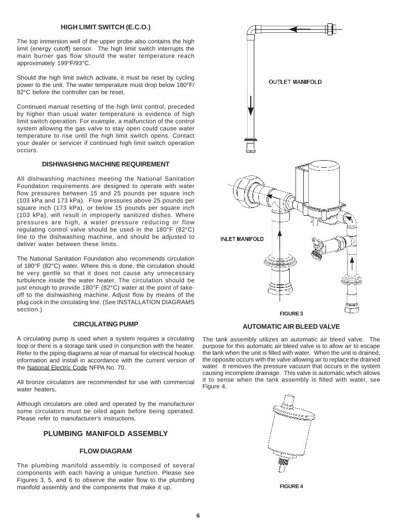
PLUMBING MANIFOLD ASSEMBLY
FLOW DIAGRAM
The plumbing manifold assembly is composed of severalcomponents with each having a unique function. Please seeFigures 3, 5, and 6 to observe the water flow to the plumbingmanifold assembly and the components that make it up.
FIGURE 3
AUTOMATIC AIR BLEED VALVE
The tank assembly utilizes an automatic air bleed valve. Thepurpose for this automatic air bleed valve is to allow air to escapethe tank when the unit is filled with water. When the unit is drained,the opposite occurs with the valve allowing air to replace the drainedwater. It removes the pressure vacuum that occurs in the systemcausing incomplete drainage. This valve is automatic which allowsit to sense when the tank assembly is filled with water, seeFigure 4.
FIGURE 4
7
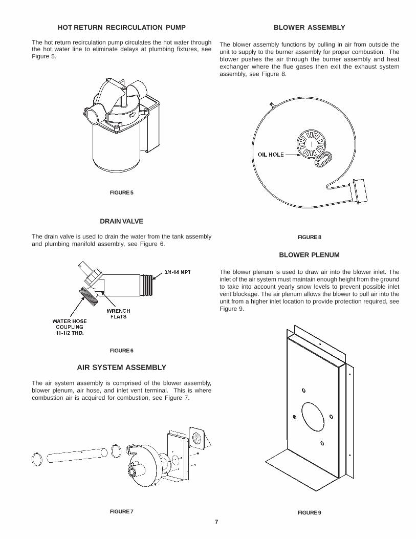
BLOWER ASSEMBLY
The blower assembly functions by pulling in air from outside theunit to supply to the burner assembly for proper combustion. Theblower pushes the air through the burner assembly and heatexchanger where the flue gases then exit the exhaust systemassembly, see Figure 8.
FIGURE 8
BLOWER PLENUM
The blower plenum is used to draw air into the blower inlet. Theinlet of the air system must maintain enough height from the groundto take into account yearly snow levels to prevent possible inletvent blockage. The air plenum allows the blower to pull air into theunit from a higher inlet location to provide protection required, seeFigure 9.
FIGURE 9
HOT RETURN RECIRCULATION PUMP
The hot return recirculation pump circulates the hot water throughthe hot water line to eliminate delays at plumbing fixtures, seeFigure 5.
FIGURE 5
DRAIN VALVE
The drain valve is used to drain the water from the tank assemblyand plumbing manifold assembly, see Figure 6.
FIGURE 6
AIR SYSTEM ASSEMBLY
The air system assembly is comprised of the blower assembly,blower plenum, air hose, and inlet vent terminal. This is wherecombustion air is acquired for combustion, see Figure 7.
FIGURE 7
8
AIR HOSE
The air hose is used to provide a flexible air path from the blowerto the burner assembly. It is held in place with two standard hoseclamps, see Figure 10.
FIGURE 10
FLUE ADAPTER
The flue adapter is made of a flat metal plate with an exhaustadapter to mate with the exhaust elbow. This is where the fluegases exit the heat exchanger. This is a very hot region and iscovered with a layer of high temperature fiberglass insulation, seeFigure 11.
FIGURE 11
EXHAUST VENT
The exhaust vent elbow mates with the flue adapter. The elbowmates with the exhaust terminal to dispose the flue gases to theoutdoors. This venting section is covered with a fiberglassinsulated wrap to protect from heat and condensation. Thesepipes are sealed with a high temperature gasket integral to thevent pipe fittings, see Figure 12.
FIGURE 12
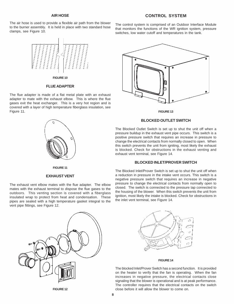
CONTROL SYSTEM
The control system is comprised of an Outdoor Interface Modulethat monitors the functions of the WR ignition system, pressureswitches, low water cutoff and temperatures in the tank.
FIGURE 13
BLOCKED OUTLET SWITCH
The Blocked Outlet Switch is set up to shut the unit off when apressure buildup in the exhaust vent pipe occurs. This switch is apositive pressure switch that requires an increase in pressure tochange the electrical contacts from normally closed to open. Whenthis switch prevents the unit from igniting, most likely the exhaustis blocked. Check for obstructions in the exhaust venting andexhaust vent terminal, see Figure 14.
BLOCKED INLET/PROVER SWITCH
The Blocked Inlet/Prover Switch is set up to shut the unit off whena reduction in pressure in the intake vent occurs. This switch is anegative pressure switch that requires an increase in negativepressure to change the electrical contacts from normally open toclosed. The switch is connected to the pressure tap connected tothe housing of the blower. When this switch prevents the unit fromignition, most likely the intake is blocked. Check for obstructions inthe inlet vent terminal, see Figure 14.
FIGURE 14
The blocked Inlet/Prover Switch has a second function. It is providedon the heater to verify that the fan is operating. When the fanincreases in negative pressure, the electrical contacts closesignaling that the blower is operational and is at peak performance.The controller requires that the electrical contacts on the switchclose before it will allow the blower to come on.
9
LOW GAS PRESSURE SWITCH
The Low Gas Pressure Switch is a single pole, normally openpressure switch that will close its contacts when a rising pressureof 6.2 inches (1.53 kPa) w.c. is encountered. The contacts willopen when the pressure falls below the fixed set point of 6.2 inchesof w.c. The Low Gas Pressure Switch monitors the gas supplypressure to the heater. If the gas supply falls below the 6.2 inchesof w.c., the main burner is extinguished (if heater is running) or theheater will not start up, see Figure 15.
FIGURE 15
ON/OFF SWITCH
The ON/OFF Switch is a single pole, single throw rocker switch.This switch provides 120V from the electrical source to the heater,see Figure 16.
FIGURE 16
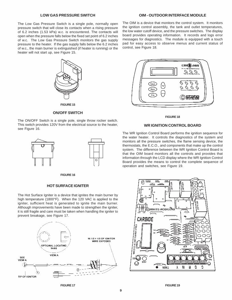
HOT SURFACE IGNITER
The Hot Surface Igniter is a device that ignites the main burner byhigh temperature (1800°F). When the 120 VAC is applied to theigniter, sufficient heat is generated to ignite the main burner.Although improvements have been made to strengthen the igniter,it is still fragile and care must be taken when handling the igniter toprevent breakage, see Figure 17.
FIGURE 17
OIM - OUTDOOR INTERFACE MODULE
The OIM is a device that monitors the control system. It monitorsthe ignition control assembly, the tank and outlet temperatures,the low water cutoff device, and the pressure switches. The displayboard provides operating information. It records and logs errormessages for diagnostics. The module is equipped with a touchpad for easy access to observe menus and current status ofcontrol, see Figure 18.
FIGURE 18
WR IGNITION CONTROL BOARD
The WR Ignition Control Board performs the ignition sequence forthe water heater. It controls the diagnostics of the system andmonitors all the pressure switches, the flame sensing device, thethermostats, the E.C.O., and components that make up the controlsystem. The difference between the WR Ignition Control Board isthat the OIM board monitors all the controls and provides thatinformation through the LCD display where the WR Ignition ControlBoard provides the means to control the complete sequence ofoperation and switches, see Figure 19.
FIGURE 19
10
grounding screw to tie into the metal panel to assure the unit isgrounded, see Figure 23.
FIGURE 23
TANK ASSEMBLY SYSTEM
The Tank Assembly is an 80 gallon unit with a U-shaped heatexchanger. It incorporates two inlet tubes to control flow inside thetank. The heat exchanger is equipped with a stainless steel bafflewhich is non-removable. The working pressure is 150 psi, seeFigure 24.
FIGURE 24
TANK INSULATION
The tank assembly is wrapped in foam insulation sealed inside around jacket. The ends of the tank consist of high temperaturefiberglass insulation and foam dams to prevent foam leakage,see Figure 25.
FIGURE 25
LOW WATER CUTOFF BOARD AND PROBE
The Low Water Cutoff Board and Probe monitors the water level toconfirm the tank is completely full. This function is very importantwhen the unit is first filled with water and when complete loss ofpower is encountered during freezing temperatures (in case theunit drains while using the anti-freeze kit), see Figure 20.
FIGURE 20
THERMOSTAT/E.C.O. PROBES
The Outback utilizes a two probe system. The upper probe locatedon top of the unit toward the back of the cabinet consists of athermostat and E.C.O. The thermostat monitors the top temperaturein the tank. The E.C.O. high limit switch interrupts the main burnergas flow should the water temperature reach approximately 205°F.The lower probe measures the water temperature in the lower halfof the tank assembly.
FIGURE 21
TRANSFORMER
The control system utilizes a 120/24 VAC step down transformer.Most of the control system utilizes 24 VAC for operation. See wiringdiagram for those components utilizing 24 VAC and 120 VAC, seeFigure 22.
FIGURE 22
JUNCTION BOX
The junction box is where the 120 VAC is supplied to the unit andtied into the rest of the controls. The junction box provides a
11
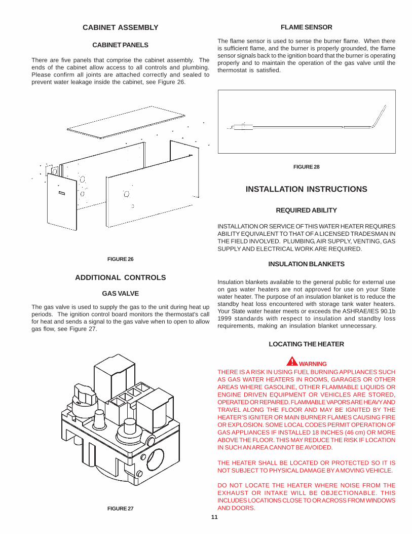
CABINET ASSEMBLY
CABINET PANELS
There are five panels that comprise the cabinet assembly. Theends of the cabinet allow access to all controls and plumbing.Please confirm all joints are attached correctly and sealed toprevent water leakage inside the cabinet, see Figure 26.
FIGURE 26
ADDITIONAL CONTROLS
GAS VALVE
The gas valve is used to supply the gas to the unit during heat upperiods. The ignition control board monitors the thermostat's callfor heat and sends a signal to the gas valve when to open to allowgas flow, see Figure 27.
FIGURE 27
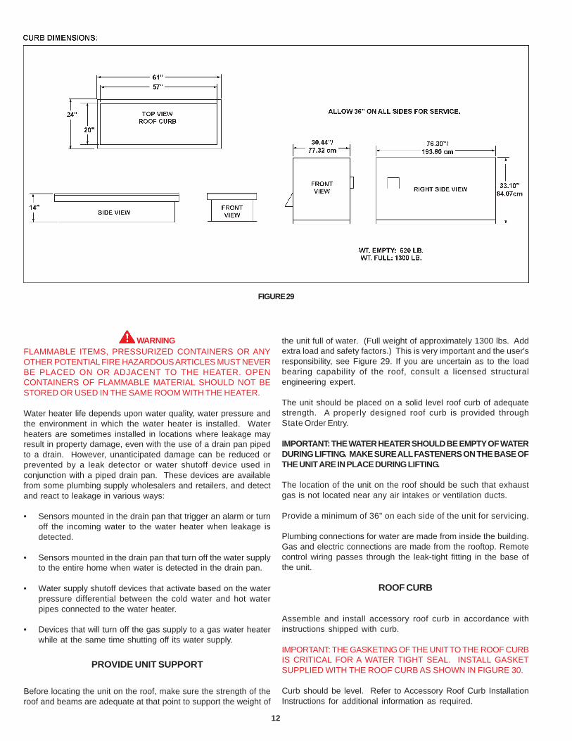
FLAME SENSOR
The flame sensor is used to sense the burner flame. When thereis sufficient flame, and the burner is properly grounded, the flamesensor signals back to the ignition board that the burner is operatingproperly and to maintain the operation of the gas valve until thethermostat is satisfied.
FIGURE 28
INSTALLATION INSTRUCTIONS
REQUIRED ABILITY
INSTALLATION OR SERVICE OF THIS WATER HEATER REQUIRESABILITY EQUIVALENT TO THAT OF A LICENSED TRADESMAN INTHE FIELD INVOLVED. PLUMBING, AIR SUPPLY, VENTING, GASSUPPLY AND ELECTRICAL WORK ARE REQUIRED.
INSULATION BLANKETS
Insulation blankets available to the general public for external useon gas water heaters are not approved for use on your Statewater heater. The purpose of an insulation blanket is to reduce thestandby heat loss encountered with storage tank water heaters.Your State water heater meets or exceeds the ASHRAE/IES 90.1b1999 standards with respect to insulation and standby lossrequirements, making an insulation blanket unnecessary.
LOCATING THE HEATER
WARNINGTHERE IS A RISK IN USING FUEL BURNING APPLIANCES SUCHAS GAS WATER HEATERS IN ROOMS, GARAGES OR OTHERAREAS WHERE GASOLINE, OTHER FLAMMABLE LIQUIDS ORENGINE DRIVEN EQUIPMENT OR VEHICLES ARE STORED,OPERATED OR REPAIRED. FLAMMABLE VAPORS ARE HEAVY ANDTRAVEL ALONG THE FLOOR AND MAY BE IGNITED BY THEHEATER’S IGNITER OR MAIN BURNER FLAMES CAUSING FIREOR EXPLOSION. SOME LOCAL CODES PERMIT OPERATION OFGAS APPLIANCES IF INSTALLED 18 INCHES (46 cm) OR MOREABOVE THE FLOOR. THIS MAY REDUCE THE RISK IF LOCATIONIN SUCH AN AREA CANNOT BE AVOIDED.
THE HEATER SHALL BE LOCATED OR PROTECTED SO IT ISNOT SUBJECT TO PHYSICAL DAMAGE BY A MOVING VEHICLE.
DO NOT LOCATE THE HEATER WHERE NOISE FROM THEEXHAUST OR INTAKE WILL BE OBJECTIONABLE. THISINCLUDES LOCATIONS CLOSE TO OR ACROSS FROM WINDOWSAND DOORS.
12
WARNINGFLAMMABLE ITEMS, PRESSURIZED CONTAINERS OR ANYOTHER POTENTIAL FIRE HAZARDOUS ARTICLES MUST NEVERBE PLACED ON OR ADJACENT TO THE HEATER. OPENCONTAINERS OF FLAMMABLE MATERIAL SHOULD NOT BESTORED OR USED IN THE SAME ROOM WITH THE HEATER.
Water heater life depends upon water quality, water pressure andthe environment in which the water heater is installed. Waterheaters are sometimes installed in locations where leakage mayresult in property damage, even with the use of a drain pan pipedto a drain. However, unanticipated damage can be reduced orprevented by a leak detector or water shutoff device used inconjunction with a piped drain pan. These devices are availablefrom some plumbing supply wholesalers and retailers, and detectand react to leakage in various ways:
• Sensors mounted in the drain pan that trigger an alarm or turnoff the incoming water to the water heater when leakage isdetected.
• Sensors mounted in the drain pan that turn off the water supplyto the entire home when water is detected in the drain pan.
• Water supply shutoff devices that activate based on the waterpressure differential between the cold water and hot waterpipes connected to the water heater.
• Devices that will turn off the gas supply to a gas water heaterwhile at the same time shutting off its water supply.
PROVIDE UNIT SUPPORT
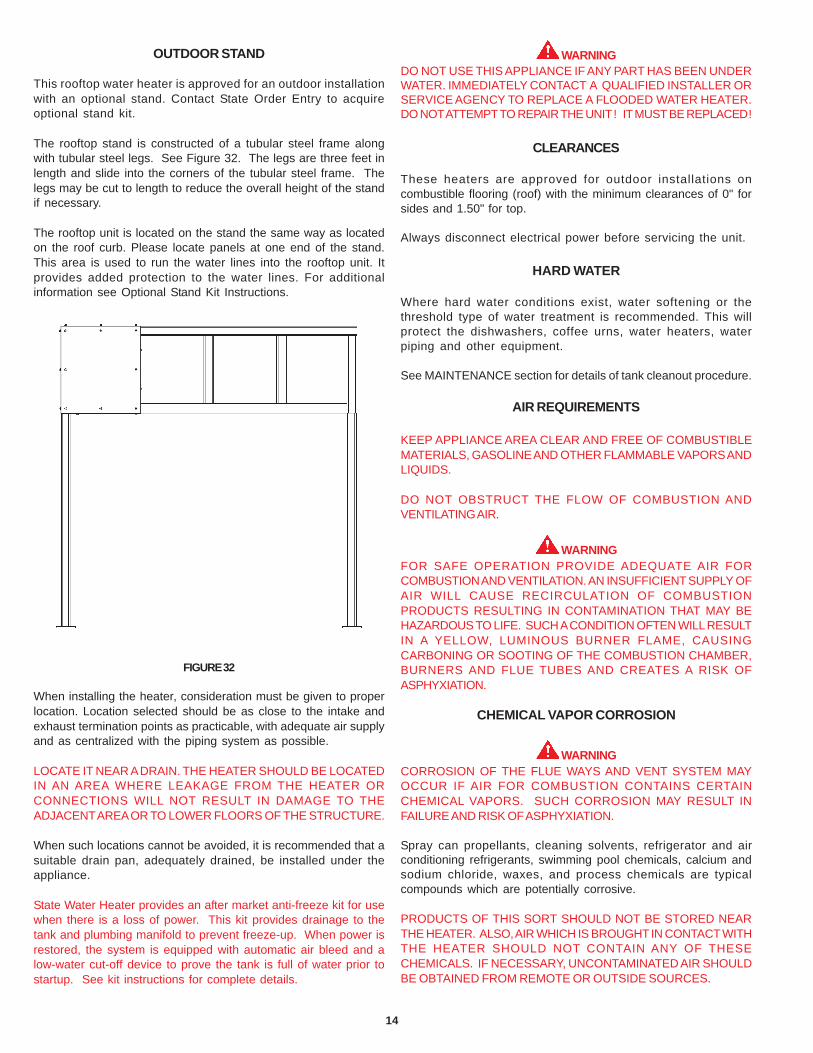
Before locating the unit on the roof, make sure the strength of theroof and beams are adequate at that point to support the weight of
the unit full of water. (Full weight of approximately 1300 lbs. Addextra load and safety factors.) This is very important and the user'sresponsibility, see Figure 29. If you are uncertain as to the loadbearing capability of the roof, consult a licensed structuralengineering expert.
The unit should be placed on a solid level roof curb of adequatestrength. A properly designed roof curb is provided throughState Order Entry.
IMPORTANT: THE WATER HEATER SHOULD BE EMPTY OF WATERDURING LIFTING. MAKE SURE ALL FASTENERS ON THE BASE OFTHE UNIT ARE IN PLACE DURING LIFTING.
The location of the unit on the roof should be such that exhaustgas is not located near any air intakes or ventilation ducts.
Provide a minimum of 36" on each side of the unit for servicing.
Plumbing connections for water are made from inside the building.Gas and electric connections are made from the rooftop. Remotecontrol wiring passes through the leak-tight fitting in the base ofthe unit.
ROOF CURB
Assemble and install accessory roof curb in accordance withinstructions shipped with curb.
IMPORTANT: THE GASKETING OF THE UNIT TO THE ROOF CURBIS CRITICAL FOR A WATER TIGHT SEAL. INSTALL GASKETSUPPLIED WITH THE ROOF CURB AS SHOWN IN FIGURE 30.
Curb should be level. Refer to Accessory Roof Curb InstallationInstructions for additional information as required.
FIGURE 29
13
RIG AND PLACE UNIT
Inspect unit for transportation damage. File any claim withtransportation agency. Keep unit upright and do not drop. Spreaderbars are not required if top crating is left on unit. Rollers may beused to move unit across the roof. Level the unit by using unitframe.
Lifting holes are provided in base rails as shown in Figure 31. Allpanels must be in place when rigging.
The unit cannot be placed on the curb with a fork lift or other liftingdevice through the fork lift openings. Doing so would interfere withplacement on the roof curb.
Maintain clearance around and above the unit to provide minimumdistance from combustible materials, proper air flow, and serviceaccess.
Do not install unit in an indoor location. Do not locate unit air inletsnear exhaust vents or other sources of contaminated air.
Be sure that unit is installed such that snow will not block thecombustion intake or flue outlet.
Unit may be installed directly on wood flooring or on Class A, B, orC roof covering material when roof curb is used.
Although unit is weatherproof, guard against water from higherlevel runoff and overhangs.
Exhaust vent terminal must have a minimum horizontal clearanceof 4 ft. from electric and gas meters, gas regulators, and gas reliefequipment. Minimum distance between unit and other electricallylive parts is 48 inches.
Flue gases can deteriorate building materials. Orient unit suchthat flue gas will not affect building materials.
Adequate combustion and ventilation air space must be providedfor proper operation of this equipment.
After unit is in position, remove rigging skids and shippingmaterials.
FIGURE 30
FIGURE 31
14
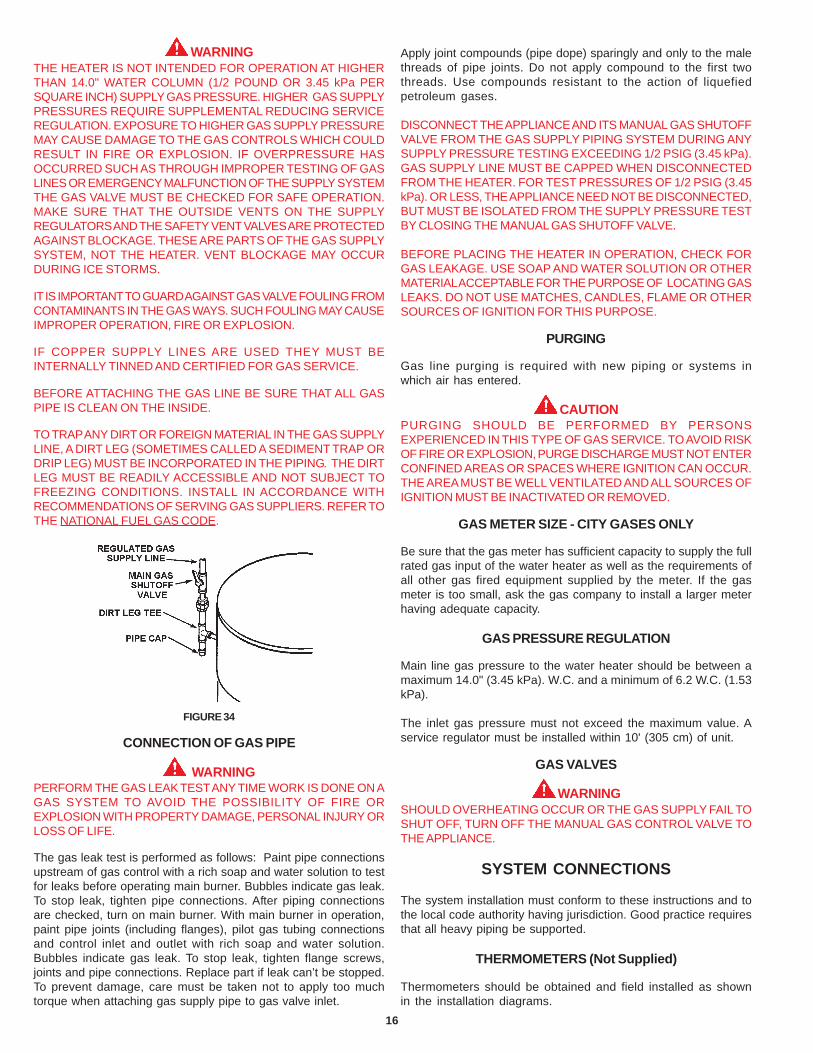
OUTDOOR STAND
This rooftop water heater is approved for an outdoor installationwith an optional stand. Contact State Order Entry to acquireoptional stand kit.
The rooftop stand is constructed of a tubular steel frame alongwith tubular steel legs. See Figure 32. The legs are three feet inlength and slide into the corners of the tubular steel frame. Thelegs may be cut to length to reduce the overall height of the standif necessary.
The rooftop unit is located on the stand the same way as locatedon the roof curb. Please locate panels at one end of the stand.This area is used to run the water lines into the rooftop unit. Itprovides added protection to the water lines. For additionalinformation see Optional Stand Kit Instructions.
FIGURE 32
When installing the heater, consideration must be given to properlocation. Location selected should be as close to the intake andexhaust termination points as practicable, with adequate air supplyand as centralized with the piping system as possible.
LOCATE IT NEAR A DRAIN. THE HEATER SHOULD BE LOCATEDIN AN AREA WHERE LEAKAGE FROM THE HEATER ORCONNECTIONS WILL NOT RESULT IN DAMAGE TO THEADJACENT AREA OR TO LOWER FLOORS OF THE STRUCTURE.
When such locations cannot be avoided, it is recommended that asuitable drain pan, adequately drained, be installed under theappliance.
State Water Heater provides an after market anti-freeze kit for usewhen there is a loss of power. This kit provides drainage to thetank and plumbing manifold to prevent freeze-up. When power isrestored, the system is equipped with automatic air bleed and alow-water cut-off device to prove the tank is full of water prior tostartup. See kit instructions for complete details.
WARNINGDO NOT USE THIS APPLIANCE IF ANY PART HAS BEEN UNDERWATER. IMMEDIATELY CONTACT A QUALIFIED INSTALLER ORSERVICE AGENCY TO REPLACE A FLOODED WATER HEATER.DO NOT ATTEMPT TO REPAIR THE UNIT! IT MUST BE REPLACED!
CLEARANCES
These heaters are approved for outdoor installations oncombustible flooring (roof) with the minimum clearances of 0" forsides and 1.50" for top.
Always disconnect electrical power before servicing the unit.
HARD WATER
Where hard water conditions exist, water softening or thethreshold type of water treatment is recommended. This willprotect the dishwashers, coffee urns, water heaters, waterpiping and other equipment.
See MAINTENANCE section for details of tank cleanout procedure.
AIR REQUIREMENTS
KEEP APPLIANCE AREA CLEAR AND FREE OF COMBUSTIBLEMATERIALS, GASOLINE AND OTHER FLAMMABLE VAPORS ANDLIQUIDS.
DO NOT OBSTRUCT THE FLOW OF COMBUSTION ANDVENTILATING AIR.
WARNINGFOR SAFE OPERATION PROVIDE ADEQUATE AIR FORCOMBUSTION AND VENTILATION. AN INSUFFICIENT SUPPLY OFAIR WILL CAUSE RECIRCULATION OF COMBUSTIONPRODUCTS RESULTING IN CONTAMINATION THAT MAY BEHAZARDOUS TO LIFE. SUCH A CONDITION OFTEN WILL RESULTIN A YELLOW, LUMINOUS BURNER FLAME, CAUSINGCARBONING OR SOOTING OF THE COMBUSTION CHAMBER,BURNERS AND FLUE TUBES AND CREATES A RISK OFASPHYXIATION.
CHEMICAL VAPOR CORROSION
WARNINGCORROSION OF THE FLUE WAYS AND VENT SYSTEM MAYOCCUR IF AIR FOR COMBUSTION CONTAINS CERTAINCHEMICAL VAPORS. SUCH CORROSION MAY RESULT INFAILURE AND RISK OF ASPHYXIATION.
Spray can propellants, cleaning solvents, refrigerator and airconditioning refrigerants, swimming pool chemicals, calcium andsodium chloride, waxes, and process chemicals are typicalcompounds which are potentially corrosive.
PRODUCTS OF THIS SORT SHOULD NOT BE STORED NEARTHE HEATER. ALSO, AIR WHICH IS BROUGHT IN CONTACT WITHTHE HEATER SHOULD NOT CONTAIN ANY OF THESECHEMICALS. IF NECESSARY, UNCONTAMINATED AIR SHOULDBE OBTAINED FROM REMOTE OR OUTSIDE SOURCES.
15
VENTING
WARNINGTHE INSTRUCTIONS IN THIS SECTION ON VENTING MUSTBE FOLLOWED TO AVOID CHOKED COMBUSTION ORRECIRCULATION OF FLUE GASES. SUCH CONDITIONS CAUSESOOTING OR RISKS OF FIRE AND ASPHYXIATION.
WARNINGNEVER OPERATE THE HEATER UNLESS IT IS VENTED TOTHE OUTDOORS AND HAS ADEQUATE AIR SUPPLY TO AVOIDRISKS OF IMPROPER OPERATION, FIRE, EXPLOSION ORASPHYXIATION.
CAUTIONDO NOT TERMINATE THE VENTING WHERE NOISE FROM THEEXHAUST OR INTAKE WILL BE OBJECTIONABLE. THISINCLUDES LOCATIONS CLOSE TO OR ACROSS FROM WINDOWSAND DOORS.
FIGURE 33
VENT TERMINALS
The vent system must terminate so that proper clearances aremaintained as cited in local codes or the current edition of theNational Fuel Gas Code, ANSI Z223.1/NFPA 54.
The SRT80-120NE series is designed with an internal ventconstruction. The exhaust vent terminal and the inlet air terminalare located on the sides of the appliance. Do not add vent pipe tothe appliance, see Figure 33.
Assure the exhaust vent terminal is not in a public area where thehoods are exposed. The exhaust vent terminal gets very HOTduring operation and can cause burns. Please use caution whenworking around the exhaust vent terminal.
It is imperative that the area around the vent terminal hoods arekept clear from obstructions so plenty of fresh air is available forcombustion.
The vent shall terminate a minimum of 12" (30.5 cm) above expectedsnowfall level to prevent blockage of vent termination.
WARNINGUSE ONLY THE VENT TERMINALS SUPPLIED WITH THIS UNIT.TERMINATION OF A VENT SYSTEM WITH A DEVICE OTHERTHAN THE SUPPLIED VENT TERMINATIONS WILL AFFECTSYSTEM PERFORMANCE AND RESULT IN A SAFETY HAZARD.
PRESSURE SWITCHES
The SRT80-120NE is provided with three pressure switches.These switches are essential to the safe and proper operation ofthe unit. All switches are wired in series. The controller is set up toshut the unit down whenever there is a failure of any of the switches.
CAUTIONTHE WATER HEATER IS POLARITY SENSITIVE. BEFOREAPPLYING ELECTRICITY TO THIS HEATER BE CERTAIN THATSUPPLY NEUTRAL WIRE TO GROUND CHECK INDICATES ZEROVOLTAGE.
GAS PIPING
Contact your local gas service company to ensure that adequategas service is available and to review applicable installation codesfor your area.
TABLE 3MAXIMUM CAPACITY OF PIPE IN CUBIC FEET OF GAS PER HOUR
(Based upon a Pressure Drop of 0.5 inch Water Columnand 0.6 Specific Gravity Gas
Size the main gas line in accordance with Table 3. The figuresshown are for straight lengths of pipe at 0.5 in. (125 kPa) W.C.pressure drop, which is considered normal for low pressuresystems. Note that fittings such as elbows and tees will add to thepipe pressure drop.
CAUTIONDO NOT USE FLEXIBLE GAS PIPING.
LENGTH NORMAL IRON PIPE SIZES (INCHES)IN INPUT IN THOUSANDS BTU/HR
WARNINGTHE HEATER IS NOT INTENDED FOR OPERATION AT HIGHERTHAN 14.0" WATER COLUMN (1/2 POUND OR 3.45 kPa PERSQUARE INCH) SUPPLY GAS PRESSURE. HIGHER GAS SUPPLYPRESSURES REQUIRE SUPPLEMENTAL REDUCING SERVICEREGULATION. EXPOSURE TO HIGHER GAS SUPPLY PRESSUREMAY CAUSE DAMAGE TO THE GAS CONTROLS WHICH COULDRESULT IN FIRE OR EXPLOSION. IF OVERPRESSURE HASOCCURRED SUCH AS THROUGH IMPROPER TESTING OF GASLINES OR EMERGENCY MALFUNCTION OF THE SUPPLY SYSTEMTHE GAS VALVE MUST BE CHECKED FOR SAFE OPERATION.MAKE SURE THAT THE OUTSIDE VENTS ON THE SUPPLYREGULATORS AND THE SAFETY VENT VALVES ARE PROTECTEDAGAINST BLOCKAGE. THESE ARE PARTS OF THE GAS SUPPLYSYSTEM, NOT THE HEATER. VENT BLOCKAGE MAY OCCURDURING ICE STORMS.
IT IS IMPORTANT TO GUARD AGAINST GAS VALVE FOULING FROMCONTAMINANTS IN THE GAS WAYS. SUCH FOULING MAY CAUSEIMPROPER OPERATION, FIRE OR EXPLOSION.
IF COPPER SUPPLY LINES ARE USED THEY MUST BEINTERNALLY TINNED AND CERTIFIED FOR GAS SERVICE.
BEFORE ATTACHING THE GAS LINE BE SURE THAT ALL GASPIPE IS CLEAN ON THE INSIDE.
TO TRAP ANY DIRT OR FOREIGN MATERIAL IN THE GAS SUPPLYLINE, A DIRT LEG (SOMETIMES CALLED A SEDIMENT TRAP ORDRIP LEG) MUST BE INCORPORATED IN THE PIPING. THE DIRTLEG MUST BE READILY ACCESSIBLE AND NOT SUBJECT TOFREEZING CONDITIONS. INSTALL IN ACCORDANCE WITHRECOMMENDATIONS OF SERVING GAS SUPPLIERS. REFER TOTHE NATIONAL FUEL GAS CODE.
FIGURE 34
CONNECTION OF GAS PIPE
WARNINGPERFORM THE GAS LEAK TEST ANY TIME WORK IS DONE ON AGAS SYSTEM TO AVOID THE POSSIBILITY OF FIRE OREXPLOSION WITH PROPERTY DAMAGE, PERSONAL INJURY ORLOSS OF LIFE.
The gas leak test is performed as follows: Paint pipe connectionsupstream of gas control with a rich soap and water solution to testfor leaks before operating main burner. Bubbles indicate gas leak.To stop leak, tighten pipe connections. After piping connectionsare checked, turn on main burner. With main burner in operation,paint pipe joints (including flanges), pilot gas tubing connectionsand control inlet and outlet with rich soap and water solution.Bubbles indicate gas leak. To stop leak, tighten flange screws,joints and pipe connections. Replace part if leak can’t be stopped.To prevent damage, care must be taken not to apply too muchtorque when attaching gas supply pipe to gas valve inlet.
Apply joint compounds (pipe dope) sparingly and only to the malethreads of pipe joints. Do not apply compound to the first twothreads. Use compounds resistant to the action of liquefiedpetroleum gases.
DISCONNECT THE APPLIANCE AND ITS MANUAL GAS SHUTOFFVALVE FROM THE GAS SUPPLY PIPING SYSTEM DURING ANYSUPPLY PRESSURE TESTING EXCEEDING 1/2 PSIG (3.45 kPa).GAS SUPPLY LINE MUST BE CAPPED WHEN DISCONNECTEDFROM THE HEATER. FOR TEST PRESSURES OF 1/2 PSIG (3.45kPa). OR LESS, THE APPLIANCE NEED NOT BE DISCONNECTED,BUT MUST BE ISOLATED FROM THE SUPPLY PRESSURE TESTBY CLOSING THE MANUAL GAS SHUTOFF VALVE.
BEFORE PLACING THE HEATER IN OPERATION, CHECK FORGAS LEAKAGE. USE SOAP AND WATER SOLUTION OR OTHERMATERIAL ACCEPTABLE FOR THE PURPOSE OF LOCATING GASLEAKS. DO NOT USE MATCHES, CANDLES, FLAME OR OTHERSOURCES OF IGNITION FOR THIS PURPOSE.
PURGING
Gas line purging is required with new piping or systems inwhich air has entered.
CAUTIONPURGING SHOULD BE PERFORMED BY PERSONSEXPERIENCED IN THIS TYPE OF GAS SERVICE. TO AVOID RISKOF FIRE OR EXPLOSION, PURGE DISCHARGE MUST NOT ENTERCONFINED AREAS OR SPACES WHERE IGNITION CAN OCCUR.THE AREA MUST BE WELL VENTILATED AND ALL SOURCES OFIGNITION MUST BE INACTIVATED OR REMOVED.
GAS METER SIZE - CITY GASES ONLY
Be sure that the gas meter has sufficient capacity to supply the fullrated gas input of the water heater as well as the requirements ofall other gas fired equipment supplied by the meter. If the gasmeter is too small, ask the gas company to install a larger meterhaving adequate capacity.
GAS PRESSURE REGULATION
Main line gas pressure to the water heater should be between amaximum 14.0" (3.45 kPa). W.C. and a minimum of 6.2 W.C. (1.53kPa).
The inlet gas pressure must not exceed the maximum value. Aservice regulator must be installed within 10' (305 cm) of unit.
GAS VALVES
WARNINGSHOULD OVERHEATING OCCUR OR THE GAS SUPPLY FAIL TOSHUT OFF, TURN OFF THE MANUAL GAS CONTROL VALVE TOTHE APPLIANCE.
SYSTEM CONNECTIONS
The system installation must conform to these instructions and tothe local code authority having jurisdiction. Good practice requiresthat all heavy piping be supported.
THERMOMETERS (Not Supplied)
Thermometers should be obtained and field installed as shownin the installation diagrams.
17
Thermometers are installed in the system as a means of detectingthe temperature of the outlet water supply.
RELIEF VALVE
This heater is equipped with an approved temperature andpressure relief valve. ASME ratings cover pressure relief. CSAratings cover release rate with temperature actuation.
FOR SAFE OPERATION OF THE WATER HEATER, THE RELIEFVALVE(S) MUST NOT BE REMOVED OR PLUGGED.
In addition to the appliance relief valve, each remote storage tankwhich may be used in conjunction with this appliance shall alsobe installed with a properly sized, rated and approved temperature(ANSI) and pressure (ASME) relief valve(s). This relief valve shallcomply with the standard for relief valves and automatic gas shutoffdevices for hot water supply systems, ANSI Z21.22.
Your local code authority may have other specific relief valverequirements.
WARNINGTHE PURPOSE OF A RELIEF VALVE IS TO AVOID EXCESSIVEPRESSURE OR TEMPERATURE INTO THE STEAM RANGE,WHICH MAY CAUSE SCALDING AT FIXTURES, TANK EXPLOSION,SYSTEM OR HEATER DAMAGE. NO VALVE IS TO BE PLACEDBETWEEN THE RELIEF VALVE AND THE TANK.
A DRAIN LINE MUST BE CONNECTED TO THE RELIEF VALVE TODIRECT DISCHARGE TO A SAFE LOCATION TO AVOID SCALDINGOR WATER DAMAGE. THIS LINE MUST NOT BE REDUCED FROMTHE SIZE OF THE VALVE OUTLET AND MUST NOT CONTAINVALVES OR RESTRICTIONS, NOR SHOULD IT BE LOCATED INFREEZING AREAS. DO NOT THREAD OR CAP THE END OF THISLINE. RESTRICTED OR BLOCKED DISCHARGE WILL DEFEATTHE PURPOSE OF THE VALVE AND IS UNSAFE. THE DISCHARGELINE SHALL BE INSTALLED TO ALLOW COMPLETE DRAINAGEOF BOTH THE VALVE AND LINE.
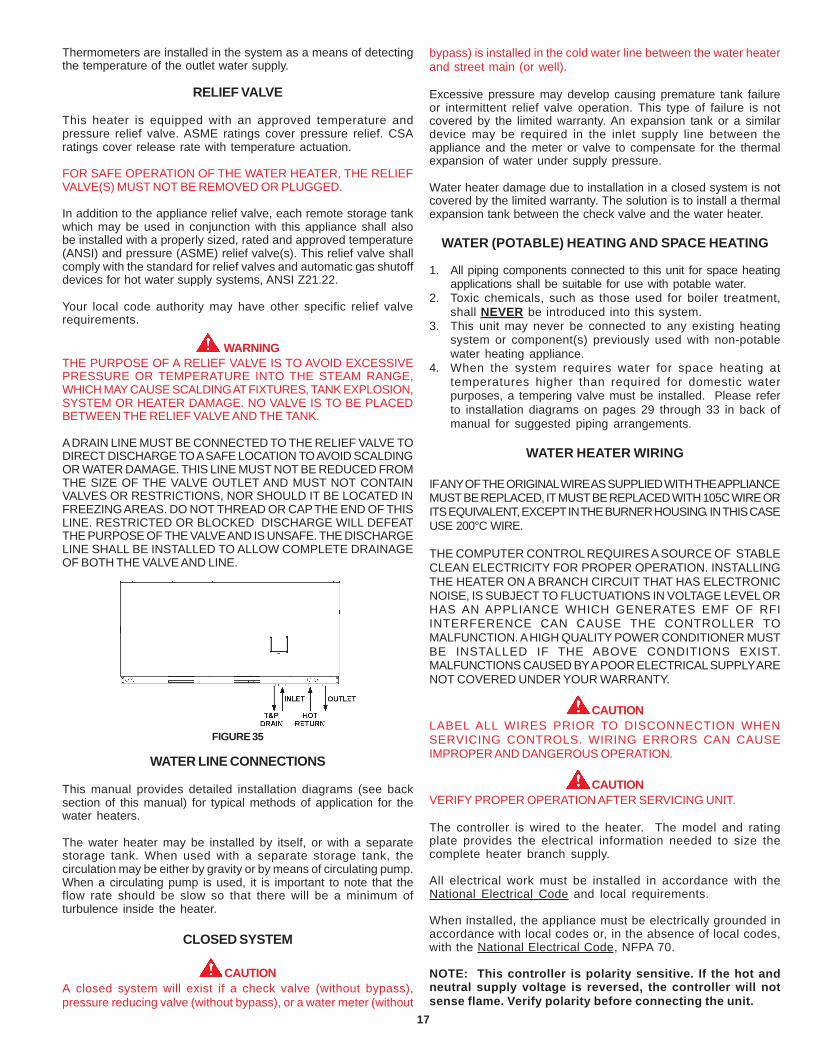
FIGURE 35
WATER LINE CONNECTIONS
This manual provides detailed installation diagrams (see backsection of this manual) for typical methods of application for thewater heaters.
The water heater may be installed by itself, or with a separatestorage tank. When used with a separate storage tank, thecirculation may be either by gravity or by means of circulating pump.When a circulating pump is used, it is important to note that theflow rate should be slow so that there will be a minimum ofturbulence inside the heater.
CLOSED SYSTEM
CAUTIONA closed system will exist if a check valve (without bypass),pressure reducing valve (without bypass), or a water meter (without
bypass) is installed in the cold water line between the water heaterand street main (or well).
Excessive pressure may develop causing premature tank failureor intermittent relief valve operation. This type of failure is notcovered by the limited warranty. An expansion tank or a similardevice may be required in the inlet supply line between theappliance and the meter or valve to compensate for the thermalexpansion of water under supply pressure.
Water heater damage due to installation in a closed system is notcovered by the limited warranty. The solution is to install a thermalexpansion tank between the check valve and the water heater.
WATER (POTABLE) HEATING AND SPACE HEATING
1. All piping components connected to this unit for space heatingapplications shall be suitable for use with potable water.
2. Toxic chemicals, such as those used for boiler treatment,shall NEVER be introduced into this system.
3. This unit may never be connected to any existing heatingsystem or component(s) previously used with non-potablewater heating appliance.
4. When the system requires water for space heating attemperatures higher than required for domestic waterpurposes, a tempering valve must be installed. Please referto installation diagrams on pages 29 through 33 in back ofmanual for suggested piping arrangements.
WATER HEATER WIRING
IF ANY OF THE ORIGINAL WIRE AS SUPPLIED WITH THE APPLIANCEMUST BE REPLACED, IT MUST BE REPLACED WITH 105C WIRE ORITS EQUIVALENT, EXCEPT IN THE BURNER HOUSING. IN THIS CASEUSE 200°C WIRE.
THE COMPUTER CONTROL REQUIRES A SOURCE OF STABLECLEAN ELECTRICITY FOR PROPER OPERATION. INSTALLINGTHE HEATER ON A BRANCH CIRCUIT THAT HAS ELECTRONICNOISE, IS SUBJECT TO FLUCTUATIONS IN VOLTAGE LEVEL ORHAS AN APPLIANCE WHICH GENERATES EMF OF RFIINTERFERENCE CAN CAUSE THE CONTROLLER TOMALFUNCTION. A HIGH QUALITY POWER CONDITIONER MUSTBE INSTALLED IF THE ABOVE CONDITIONS EXIST.MALFUNCTIONS CAUSED BY A POOR ELECTRICAL SUPPLY ARENOT COVERED UNDER YOUR WARRANTY.
CAUTIONLABEL ALL WIRES PRIOR TO DISCONNECTION WHENSERVICING CONTROLS. WIRING ERRORS CAN CAUSEIMPROPER AND DANGEROUS OPERATION.
CAUTIONVERIFY PROPER OPERATION AFTER SERVICING UNIT.
The controller is wired to the heater. The model and ratingplate provides the electrical information needed to size thecomplete heater branch supply.
All electrical work must be installed in accordance with theNational Electrical Code and local requirements.
When installed, the appliance must be electrically grounded inaccordance with local codes or, in the absence of local codes,with the National Electrical Code, NFPA 70.
NOTE: This controller is polarity sensitive. If the hot andneutral supply voltage is reversed, the controller will notsense flame. Verify polarity before connecting the unit.
18
FIG
URE
36
19
OPERATION
MENU NAVIGATION
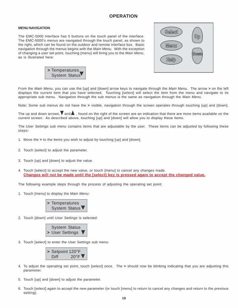
The EMC-5000 Interface has 5 buttons on the touch panel of the interface.The EMC-5000's menus are navigated through the touch panel, as shown tothe right, which can be found on the outdoor and remote interface box. Basicnavigation through the menus begins with the Main Menu. With the exceptionof changing a user set point, touching {menu} will bring you to the Main Menu,as is illustrated here:
> TemperaturesSystem Status
From the Main Menu, you can use the [up] and [down] arrow keys to navigate through the Main Menu. The arrow > on the leftdisplays the current item that you have selected. Touching [select] will select the item from the menu and navigate to itsappropriate sub menu. Navigation through the sub menus is the same as navigation through the Main Menu.
Note: Some sub menus do not have the > visible, navigation through the screen operates through touching [up] and [down].
The up and down arrows, and , found on the right of the screen are an indication that there are more items available on thecurrent screen. As described above, touching [up] and [down] will allow you to display these items.
The User Settings sub menu contains items that are adjustable by the user. These items can be adjusted by following thesesteps:
1. Move the > to the items you wish to adjust by touching [up] and [down].
2. Touch [select] to adjust the parameter.
3. Touch [up] and [down] to adjust the value.
4. Touch [select] to accept the new value, or touch [menu] to cancel any changes made.Changes will not be made until the [select} key is pressed again to accept the changed value.
The following example steps through the process of adjusting the operating set point:
1. Touch [menu] to display the Main Menu:
> TemperaturesSystem Status
2. Touch [down] until User Settings is selected:
System Status> User Settings
3. Touch [select] to enter the User Settings sub menu:
> Setpoint 120°FDiff 20°F
4. To adjust the operating set point, touch [select] once. The > should now be blinking indicating that you are adjusting thisparameter.
5. Touch [up] and [down] to adjust the parameter.
6. Touch [select] again to accept the new parameter (or touch [menu] to return to cancel any changes and return to the previoussetting).
20
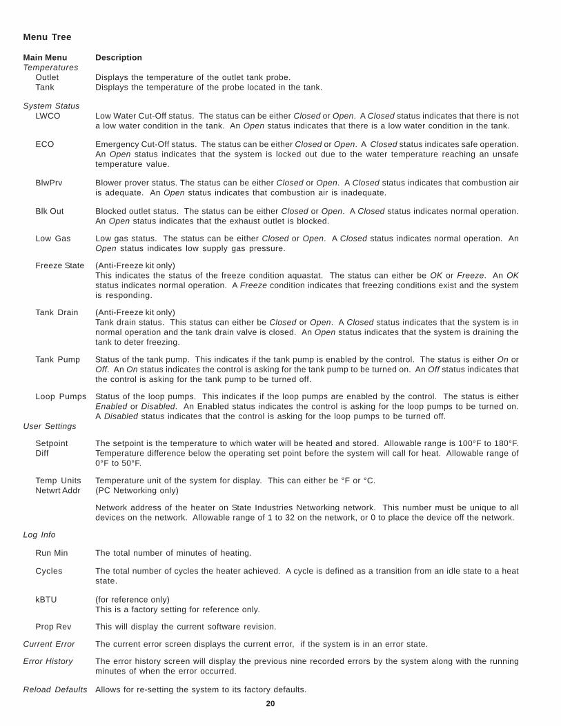
Menu Tree
Main Menu DescriptionTemperatures
Outlet Displays the temperature of the outlet tank probe.Tank Displays the temperature of the probe located in the tank.
System StatusLWCO Low Water Cut-Off status. The status can be either Closed or Open. A Closed status indicates that there is not
a low water condition in the tank. An Open status indicates that there is a low water condition in the tank.
ECO Emergency Cut-Off status. The status can be either Closed or Open. A Closed status indicates safe operation.An Open status indicates that the system is locked out due to the water temperature reaching an unsafetemperature value.
BlwPrv Blower prover status. The status can be either Closed or Open. A Closed status indicates that combustion airis adequate. An Open status indicates that combustion air is inadequate.
Blk Out Blocked outlet status. The status can be either Closed or Open. A Closed status indicates normal operation.An Open status indicates that the exhaust outlet is blocked.
Low Gas Low gas status. The status can be either Closed or Open. A Closed status indicates normal operation. AnOpen status indicates low supply gas pressure.
Freeze State (Anti-Freeze kit only)This indicates the status of the freeze condition aquastat. The status can either be OK or Freeze. An OKstatus indicates normal operation. A Freeze condition indicates that freezing conditions exist and the systemis responding.
Tank Drain (Anti-Freeze kit only)Tank drain status. This status can either be Closed or Open. A Closed status indicates that the system is innormal operation and the tank drain valve is closed. An Open status indicates that the system is draining thetank to deter freezing.
Tank Pump Status of the tank pump. This indicates if the tank pump is enabled by the control. The status is either On orOff. An On status indicates the control is asking for the tank pump to be turned on. An Off status indicates thatthe control is asking for the tank pump to be turned off.
Loop Pumps Status of the loop pumps. This indicates if the loop pumps are enabled by the control. The status is eitherEnabled or Disabled. An Enabled status indicates the control is asking for the loop pumps to be turned on.A Disabled status indicates that the control is asking for the loop pumps to be turned off.
User Settings
Setpoint The setpoint is the temperature to which water will be heated and stored. Allowable range is 100°F to 180°F.Diff Temperature difference below the operating set point before the system will call for heat. Allowable range of
0°F to 50°F.
Temp Units Temperature unit of the system for display. This can either be °F or °C.Netwrt Addr (PC Networking only)
Network address of the heater on State Industries Networking network. This number must be unique to alldevices on the network. Allowable range of 1 to 32 on the network, or 0 to place the device off the network.
Log Info
Run Min The total number of minutes of heating.
Cycles The total number of cycles the heater achieved. A cycle is defined as a transition from an idle state to a heatstate.
kBTU (for reference only)This is a factory setting for reference only.
Prop Rev This will display the current software revision.
Current Error The current error screen displays the current error, if the system is in an error state.
Error History The error history screen will display the previous nine recorded errors by the system along with the runningminutes of when the error occurred.
Reload Defaults Allows for re-setting the system to its factory defaults.
21
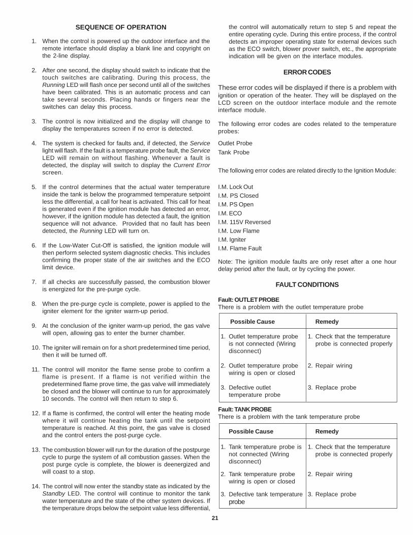
SEQUENCE OF OPERATION
1. When the control is powered up the outdoor interface and theremote interface should display a blank line and copyright onthe 2-line display.
2. After one second, the display should switch to indicate that thetouch switches are calibrating. During this process, theRunning LED will flash once per second until all of the switcheshave been calibrated. This is an automatic process and cantake several seconds. Placing hands or fingers near theswitches can delay this process.
3. The control is now initialized and the display will change todisplay the temperatures screen if no error is detected.
4. The system is checked for faults and, if detected, the Servicelight will flash. If the fault is a temperature probe fault, the ServiceLED will remain on without flashing. Whenever a fault isdetected, the display will switch to display the Current Errorscreen.
5. If the control determines that the actual water temperatureinside the tank is below the programmed temperature setpointless the differential, a call for heat is activated. This call for heatis generated even if the ignition module has detected an error,however, if the ignition module has detected a fault, the ignitionsequence will not advance. Provided that no fault has beendetected, the Running LED will turn on.
6. If the Low-Water Cut-Off is satisfied, the ignition module willthen perform selected system diagnostic checks. This includesconfirming the proper state of the air switches and the ECOlimit device.
7. If all checks are successfully passed, the combustion bloweris energized for the pre-purge cycle.
8. When the pre-purge cycle is complete, power is applied to theigniter element for the igniter warm-up period.
9. At the conclusion of the igniter warm-up period, the gas valvewill open, allowing gas to enter the burner chamber.
10. The igniter will remain on for a short predetermined time period,then it will be turned off.
11. The control will monitor the flame sense probe to confirm aflame is present. If a flame is not verified within thepredetermined flame prove time, the gas valve will immediatelybe closed and the blower will continue to run for approximately10 seconds. The control will then return to step 6.
12. If a flame is confirmed, the control will enter the heating modewhere it will continue heating the tank until the setpointtemperature is reached. At this point, the gas valve is closedand the control enters the post-purge cycle.
13. The combustion blower will run for the duration of the postpurgecycle to purge the system of all combustion gasses. When thepost purge cycle is complete, the blower is deenergized andwill coast to a stop.
14. The control will now enter the standby state as indicated by theStandby LED. The control will continue to monitor the tankwater temperature and the state of the other system devices. Ifthe temperature drops below the setpoint value less differential,
the control will automatically return to step 5 and repeat theentire operating cycle. During this entire process, if the controldetects an improper operating state for external devices suchas the ECO switch, blower prover switch, etc., the appropriateindication will be given on the interface modules.
ERROR CODES
These error codes will be displayed if there is a problem withignition or operation of the heater. They will be displayed on theLCD screen on the outdoor interface module and the remoteinterface module.
The following error codes are codes related to the temperatureprobes:
Outlet ProbeTank Probe
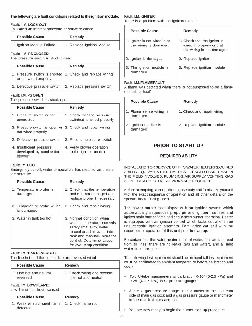
The following error codes are related directly to the Ignition Module:
4. Insufficient pressure 4. Verify blower operationdeveloped by combustion to the ignition moduleblower
Fault: I.M. ECOEmergency cut-off, water temperature has reached an unsafetemperature
Possible Cause Remedy
1. Temperature probe is 1. Check that the temperaturedamaged probe is not damaged and
replace probe if necessary
2. Temperature probe wiring 2. Check and repair wiringis damaged
3. Water in tank too hot 3. Normal condition whenwater temperature exceedssafety limit. Allow waterto cool or admit water intotank and manually reset thecontrol. Determine causefor over temp condition
Fault: I.M. 115V REVERSEDThe line hot and the neutral line are reversed wired
Possible Cause Remedy
1. Line hot and neutral 1. Check wiring and reversereversed line hot and neutral
Fault: I.M. LOW FLAMELow flame has been sensed
Possible Cause Remedy
1. Weak or insufficient flame 1. Check flame roddetected
Fault: I.M. IGNITERThere is a problem with the ignition module
Possible Cause Remedy
1. Igniter is not wired in or 1. Check that the igniter isthe wiring is damaged wired in properly or that
the wiring is not damaged
2. Igniter is damaged 2. Replace igniter
3. The ignition module is 3. Replace ignition moduledamaged
Fault: I.M. FLAME FAULTA flame was detected when there is not supposed to be a flame(no call for heat).
Possible Cause Remedy
1. Flame sense wiring is 1. Check and repair wiringdamaged
2. Ignition module is 2. Replace ignition moduledamaged
PRIOR TO START UP
REQUIRED ABILITY
INSTALLATION OR SERVICE OF THIS WATER HEATER REQUIRESABILITY EQUIVALENT TO THAT OF A LICENSED TRADESMAN INTHE FIELD INVOLVED. PLUMBING, AIR SUPPLY, VENTING, GASSUPPLY AND ELECTRICAL WORK ARE REQUIRED.
Before attempting start-up, thoroughly study and familiarize yourselfwith the exact sequence of operation and all other details on thespecific heater being used.
The power burner is equipped with an ignition system whichautomatically sequences prepurge and ignition, senses andignites main burner flame and sequences burner operation. Heateris equipped with an ignition control which locks out after threeunsuccessful ignition attempts. Familiarize yourself with thesequence of operation of this unit prior to start-up.
Be certain that the water heater is full of water, that air is purgedfrom all lines, there are no leaks (gas and water), and all inletwater lines are open.
The following test equipment should be on hand (all test equipmentmust be acclimated to ambient temperature before calibration anduse.)
– Two U-tube manometers or calibration 0-10" (0-2.5 kPa) and0-35" (0-2.5 kPa) W.C. pressure gauges.
• Attach a gas pressure gauge or manometer to the upstreamside of main gas cock and a gas pressure gauge or manometerto the manifold pressure tap.
• You are now ready to begin the burner start-up procedure.
23
OPERATING INSTRUCTIONS
IMPORTANTIT IS RECOMMENDED THAT A QUALIFIED SERVICE TECHNICIANPERFORM THE INITIAL FIRING OF THE HEATER. AT THIS TIMETHE USER SHOULD ASK THE TECHNICIAN ANY QUESTIONS INREGARD TO THE OPERATION AND MAINTENANCE OF THE UNIT.
CAUTIONBEFORE PROCEEDING WITH THE OPERATION OF THE UNIT,MAKE SURE HEATER AND SYSTEM ARE FILLED WITH WATERAND ALL AIR IS EXPELLED FROM HEATER AND PIPING.
NEVER OPERATE THE HEATER WITHOUT FIRST BEING CERTAINIT IS FILLED WITH WATER AND A TEMPERATURE AND APRESSURE RELIEF VALVE IS INSTALLED IN THE RELIEF VALVEOPENING OF THE HEATER. DO NOT ATTEMPT TO OPERATEHEATER WITH COLD WATER INLET VALVE CLOSED.
FILLING:
1. Close the heater drain valve.
2. Open a nearby hot water faucet to permit the air in the systemto escape.
3. Fully open the cold water inlet pipe valve allowing the heaterand piping to be filled.
4. Close the hot water faucet as water starts to flow.
5. The heater is ready to be operated.
THE MAIN MANUAL GAS SHUTOFF VALVE MUST HAVE BEENCLOSED FOR AT LEAST FIVE (5) MINUTES. THIS WAITING PERIODIS AN IMPORTANT SAFETY STEP. ITS PURPOSE IS TO PERMITGAS THAT MIGHT HAVE ACCUMULATED IN THE COMBUSTIONCHAMBER TO CLEAR. IF YOU DETECT GAS AT THE END OFTHIS PERIOD, DO NOT PROCEED WITH LIGHTING. RECOGNIZETHAT GAS ODOR, EVEN IF IT SEEMS WEAK, MAY INDICATE THEPRESENCE OF ACCUMULATED GAS SOMEPLACE IN THE AREAWITH A RISK OF FIRE OR EXPLOSION. SEE THE FRONT PAGEFOR STEPS TO BE TAKEN.
DO NOT USE THIS HEATER IF ANY PART HAS BEEN UNDERWATER. IMMEDIATELY CALL A QUALIFIED SERVICE TECHNICIANTO INSPECT THE HEATER AND TO REPLACE ANY PART OF THECONTROL SYSTEM AND ANY GAS CONTROL WHICH HASBEEN UNDER WATER.
LIGHT THE UNIT IN ACCORDANCE WITH THE OPERATINGINSTRUCTIONS LABEL ATTACHED TO THE HEATER.
THESE INSTRUCTIONS ARE REPEATED IN THE LIGHTING ANDOPERATING LABEL ILLUSTRATION IN THIS MANUAL.
INITIAL START-UP
A minimum gas supply pressure of 6.2" W.C. for natural gas isrequired before making any adjustment to the gas control pressureregulator. Attempts to adjust the regulator during periods of lowgas supply pressure could result in overfiring of the heater whenthe gas supply pressure returns to normal.
1. Check gas line pressure with a manometer.
2. Check manifold pressure (see Table 4) using a pressure gauge(manometer) connected to the manifold pressure tap on thegas control valve.
If full rate adjustment is required, remove cover screw from top ofthe gas control valve.
Using a small screwdriver, turn adjusting screw clockwise toincrease or counterclockwise to decrease gas pressure toobtain 4.5" (1 kPa) for natural gas Water Column.
3. Cycle the burner on and off several times to check its operation.
4. Check the operation of the limit and operating controls.
5. Check the input rate:
For appliance installation locations with elevations above 2000feet (610 m) refer to HIGH ALTITUDE INSTALLATIONS section ofthis manual.
a. Attach a pressure gauge (manometer) to the manifoldpressure tap and refer to Table 4, page 26 for correctpressure.
b. Use this formula to “clock” the meter. Be sure other gasconsuming appliances are not operating during this interval.
3600 X H = Btuh T
Should it be necessary to adjust the gas pressure to theburner, to obtain the full input rate, the steps below shouldbe followed:
T = Time in seconds to burn 1 cubic foot of gas. (With a stopwatchread the gas meter and measure the amount of time requiredfor the heater to consume 1 cubic foot of gas.)
H = Heating value of gas (in Btu’s per cubic foot of gas).
Btuh = Actual heater input rate, in Btuh.
EXAMPLE: (Using RTF-120 heater)
T = 18.9 seconds
H = 1050 Btu/ft.3
For high altitude installations, compare result to the derated inputrequired for the elevation at the installation location.
c. Remove the pressure regulator cover screw and adjust thepressure by turning the adjusting screw with a smallscrewdriver. Do not exceed 4.5" (1 kPa) Water Column.
Clockwise to increase gas pressure and input rate.
Counterclockwise to decrease gas pressure and inputrate.
d. “Clock” the meter as in step (b) above.
3600 X 1050 = 199,900 Btuh (59 kW)18.9
24
e. Repeat steps (c) and (d) until the specified input rate isachieved.
f. Turn the manual gas valve to “OFF”. Replace the pressureregulator cover screw. Remove the pressure gauge ormanometer from the manifold pressure tap. Replace the setscrew in the manifold pressure tap. If the gas pressureregulator cannot be adjusted to give the full input rating withsufficient gas pressure at the valve, check to ensure the unitis equipped with the correct orifice.
WARNINGUNDER NO CIRCUMSTANCES SHOULD THE INPUT EXCEEDTHE RATE SHOWN ON THE HEATER RATING PLATE.OVERFIRING COULD RESULT IN DAMAGE OR SOOTING OF THEHEATER.
CATHODIC PROTECTION
CAUTIONHYDROGEN GAS CAN BE PRODUCED IN A HOT WATER SYSTEMSERVED BY THIS HEATER THAT HAS NOT BEEN USED FOR ALONG PERIOD OF TIME (GENERALLY TWO WEEKS OR MORE).HYDROGEN GAS IS EXTREMELY FLAMMABLE. To reduce the riskof injury under these conditions, it is recommended that a hotwater faucet be opened for several minutes before using anyelectrical appliance connected to the hot water system. If hydrogen
is present, there will probably be an unusual sound such as airescaping through the pipe as the water begins to flow. There shouldbe no smoking or open flame near the faucet at the time it is open.
PRECAUTIONS
IF THE UNIT IS EXPOSED TO THE FOLLOWING, DO NOTOPERATE HEATER UNTIL ALL CORRECTIVE STEPS HAVE BEENMADE BY A QUALIFIED SERVICEMAN.
1. FLOODING TO OR ABOVE THE LEVEL OF THE BURNER ORCONTROLS
2. EXTERNAL FIRING
3. DAMAGE
4. FIRING WITHOUT WATER
5. SOOTING
NEVER OPERATE THE HEATER WITHOUT FIRST BEING CERTAINIT IS FILLED WITH WATER AND A TEMPERATURE ANDPRESSURE RELIEF VALVE IS INSTALLED IN THE RELIEF VALVEOPENING OF THE HEATER.
SHOULD OVERHEATING OCCUR OR THE GAS SUPPLY FAIL TOSHUT OFF, TURN OFF THE MANUAL GAS CONTROL VALVE TOTHE APPLIANCE.
25
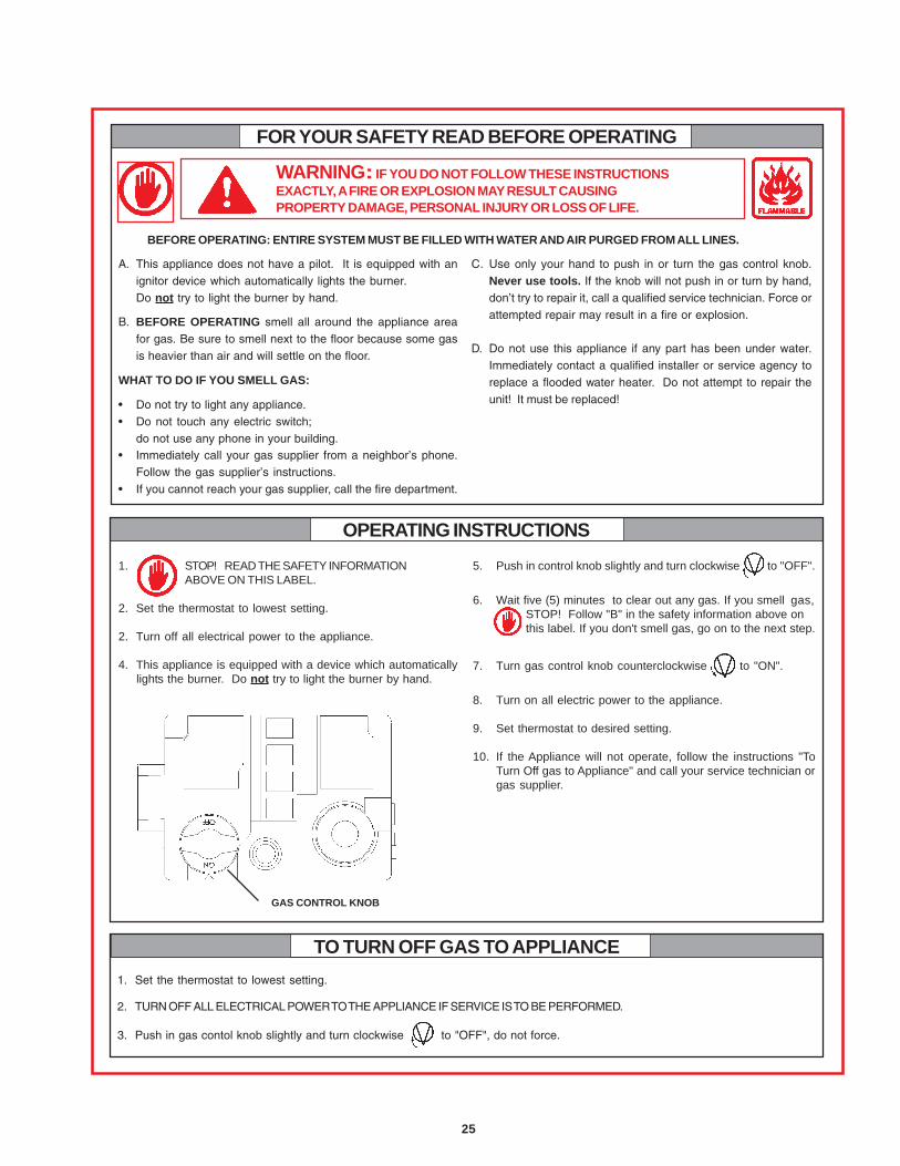
WARNING: IF YOU DO NOT FOLLOW THESE INSTRUCTIONSEXACTLY, A FIRE OR EXPLOSION MAY RESULT CAUSINGPROPERTY DAMAGE, PERSONAL INJURY OR LOSS OF LIFE.
FOR YOUR SAFETY READ BEFORE OPERATING
C. Use only your hand to push in or turn the gas control knob.Never use tools. If the knob will not push in or turn by hand,don’t try to repair it, call a qualified service technician. Force orattempted repair may result in a fire or explosion.
D. Do not use this appliance if any part has been under water.Immediately contact a qualified installer or service agency toreplace a flooded water heater. Do not attempt to repair theunit! It must be replaced!
OPERATING INSTRUCTIONS
1. Set the thermostat to lowest setting.
2. TURN OFF ALL ELECTRICAL POWER TO THE APPLIANCE IF SERVICE IS TO BE PERFORMED.
3. Push in gas contol knob slightly and turn clockwise to "OFF", do not force.
TO TURN OFF GAS TO APPLIANCE
BEFORE OPERATING: ENTIRE SYSTEM MUST BE FILLED WITH WATER AND AIR PURGED FROM ALL LINES.
1. STOP! READ THE SAFETY INFORMATIONABOVE ON THIS LABEL.
2. Set the thermostat to lowest setting.
2. Turn off all electrical power to the appliance.
4. This appliance is equipped with a device which automaticallylights the burner. Do not try to light the burner by hand.
5. Push in control knob slightly and turn clockwise to "OFF".
6. Wait five (5) minutes to clear out any gas. If you smell gas,STOP! Follow "B" in the safety information above onthis label. If you don't smell gas, go on to the next step.
7. Turn gas control knob counterclockwise to "ON".
8. Turn on all electric power to the appliance.
9. Set thermostat to desired setting.
10. If the Appliance will not operate, follow the instructions "ToTurn Off gas to Appliance" and call your service technician orgas supplier.
A. This appliance does not have a pilot. It is equipped with anignitor device which automatically lights the burner.Do not try to light the burner by hand.
B. BEFORE OPERATING smell all around the appliance areafor gas. Be sure to smell next to the floor because some gasis heavier than air and will settle on the floor.
WHAT TO DO IF YOU SMELL GAS:
• Do not try to light any appliance.• Do not touch any electric switch;
do not use any phone in your building.• Immediately call your gas supplier from a neighbor’s phone.
Follow the gas supplier’s instructions.• If you cannot reach your gas supplier, call the fire department.
GAS CONTROL KNOB
26
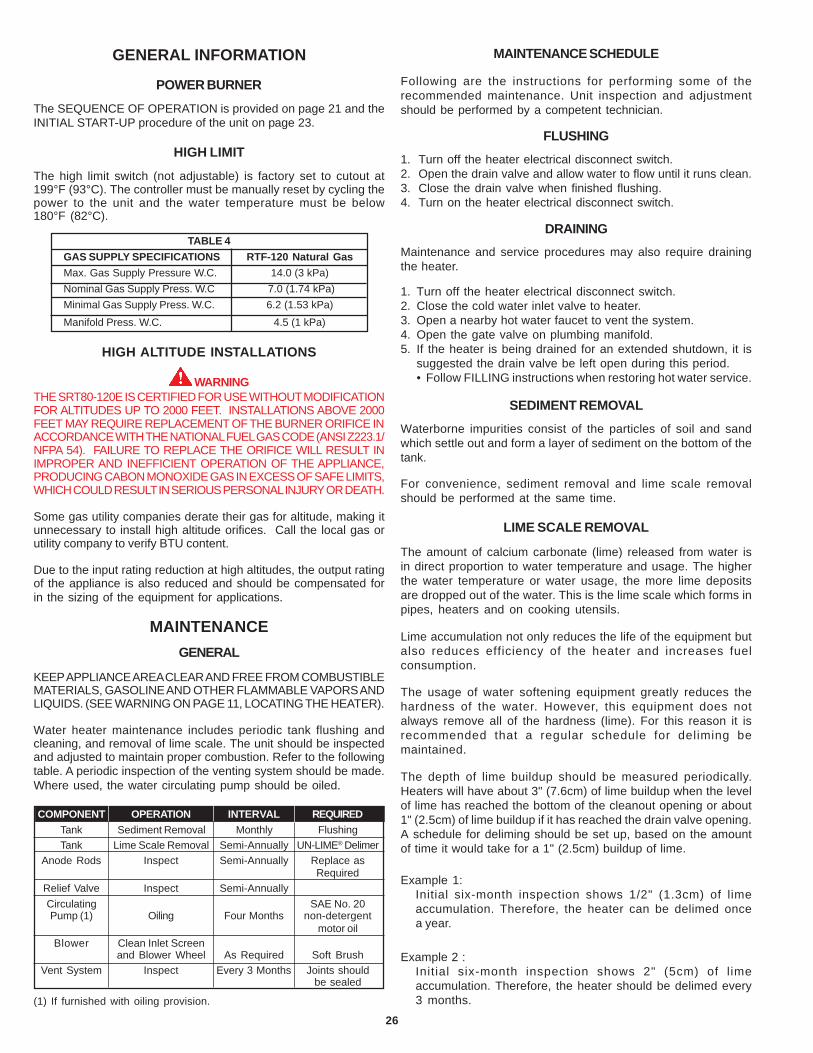
GENERAL INFORMATION
POWER BURNER
The SEQUENCE OF OPERATION is provided on page 21 and theINITIAL START-UP procedure of the unit on page 23.
HIGH LIMIT
The high limit switch (not adjustable) is factory set to cutout at199°F (93°C). The controller must be manually reset by cycling thepower to the unit and the water temperature must be below180°F (82°C).
WARNINGTHE SRT80-120E IS CERTIFIED FOR USE WITHOUT MODIFICATIONFOR ALTITUDES UP TO 2000 FEET. INSTALLATIONS ABOVE 2000FEET MAY REQUIRE REPLACEMENT OF THE BURNER ORIFICE INACCORDANCE WITH THE NATIONAL FUEL GAS CODE (ANSI Z223.1/NFPA 54). FAILURE TO REPLACE THE ORIFICE WILL RESULT INIMPROPER AND INEFFICIENT OPERATION OF THE APPLIANCE,PRODUCING CABON MONOXIDE GAS IN EXCESS OF SAFE LIMITS,WHICH COULD RESULT IN SERIOUS PERSONAL INJURY OR DEATH.
Some gas utility companies derate their gas for altitude, making itunnecessary to install high altitude orifices. Call the local gas orutility company to verify BTU content.
Due to the input rating reduction at high altitudes, the output ratingof the appliance is also reduced and should be compensated forin the sizing of the equipment for applications.
MAINTENANCEGENERAL
KEEP APPLIANCE AREA CLEAR AND FREE FROM COMBUSTIBLEMATERIALS, GASOLINE AND OTHER FLAMMABLE VAPORS ANDLIQUIDS. (SEE WARNING ON PAGE 11, LOCATING THE HEATER).
Water heater maintenance includes periodic tank flushing andcleaning, and removal of lime scale. The unit should be inspectedand adjusted to maintain proper combustion. Refer to the followingtable. A periodic inspection of the venting system should be made.Where used, the water circulating pump should be oiled.
and Blower Wheel As Required Soft BrushVent System Inspect Every 3 Months Joints should
be sealed
MAINTENANCE SCHEDULE
Following are the instructions for performing some of therecommended maintenance. Unit inspection and adjustmentshould be performed by a competent technician.
FLUSHING1. Turn off the heater electrical disconnect switch.2. Open the drain valve and allow water to flow until it runs clean.3. Close the drain valve when finished flushing.4. Turn on the heater electrical disconnect switch.
DRAININGMaintenance and service procedures may also require drainingthe heater.
1. Turn off the heater electrical disconnect switch.2. Close the cold water inlet valve to heater.3. Open a nearby hot water faucet to vent the system.4. Open the gate valve on plumbing manifold.5. If the heater is being drained for an extended shutdown, it is
suggested the drain valve be left open during this period.• Follow FILLING instructions when restoring hot water service.
SEDIMENT REMOVALWaterborne impurities consist of the particles of soil and sandwhich settle out and form a layer of sediment on the bottom of thetank.
For convenience, sediment removal and lime scale removalshould be performed at the same time.
LIME SCALE REMOVAL
The amount of calcium carbonate (lime) released from water isin direct proportion to water temperature and usage. The higherthe water temperature or water usage, the more lime depositsare dropped out of the water. This is the lime scale which forms inpipes, heaters and on cooking utensils.
Lime accumulation not only reduces the life of the equipment butalso reduces efficiency of the heater and increases fuelconsumption.
The usage of water softening equipment greatly reduces thehardness of the water. However, this equipment does notalways remove all of the hardness (lime). For this reason it isrecommended that a regular schedule for deliming bemaintained.
The depth of lime buildup should be measured periodically.Heaters will have about 3" (7.6cm) of lime buildup when the levelof lime has reached the bottom of the cleanout opening or about1" (2.5cm) of lime buildup if it has reached the drain valve opening.A schedule for deliming should be set up, based on the amountof time it would take for a 1" (2.5cm) buildup of lime.
Example 1:Initial six-month inspection shows 1/2" (1.3cm) of limeaccumulation. Therefore, the heater can be delimed oncea year.
Example 2 :Initial six-month inspection shows 2" (5cm) of l imeaccumulation. Therefore, the heater should be delimed every3 months.
27
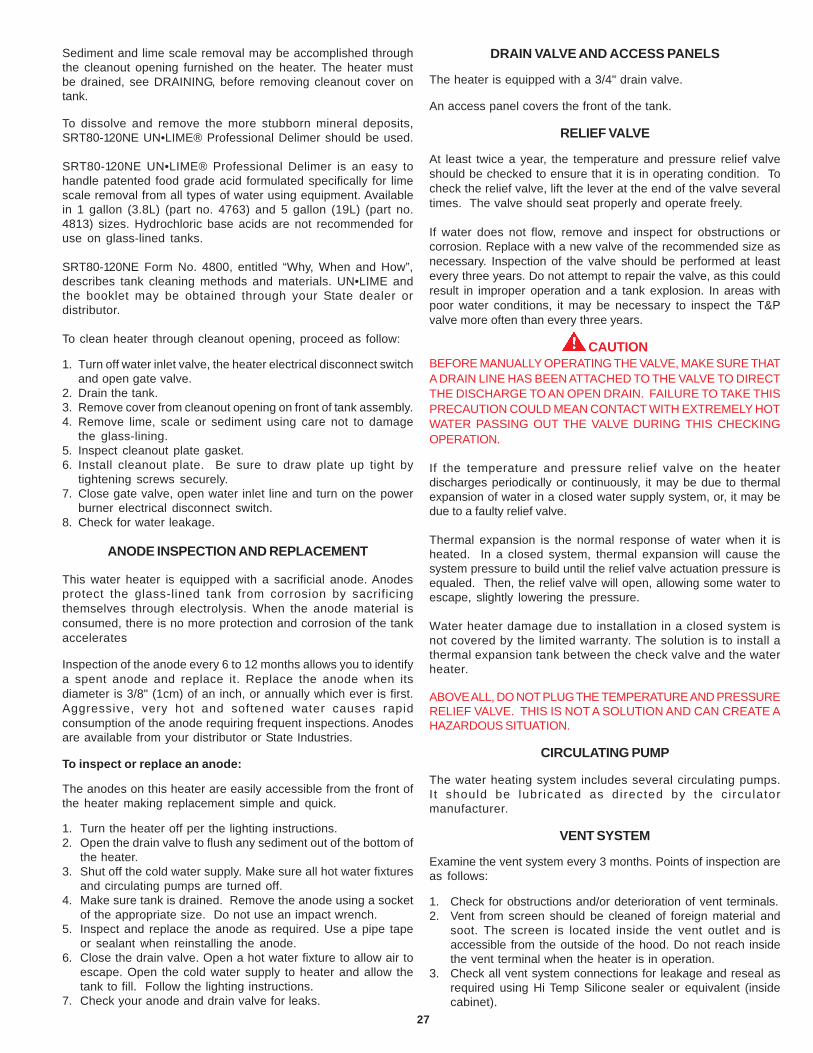
Sediment and lime scale removal may be accomplished throughthe cleanout opening furnished on the heater. The heater mustbe drained, see DRAINING, before removing cleanout cover ontank.
To dissolve and remove the more stubborn mineral deposits,SRT80-120NE UN•LIME® Professional Delimer should be used.
SRT80-120NE UN•LIME® Professional Delimer is an easy tohandle patented food grade acid formulated specifically for limescale removal from all types of water using equipment. Availablein 1 gallon (3.8L) (part no. 4763) and 5 gallon (19L) (part no.4813) sizes. Hydrochloric base acids are not recommended foruse on glass-lined tanks.
SRT80-120NE Form No. 4800, entitled “Why, When and How”,describes tank cleaning methods and materials. UN•LIME andthe booklet may be obtained through your State dealer ordistributor.
To clean heater through cleanout opening, proceed as follow:
1. Turn off water inlet valve, the heater electrical disconnect switchand open gate valve.
2. Drain the tank.3. Remove cover from cleanout opening on front of tank assembly.4. Remove lime, scale or sediment using care not to damage
the glass-lining.5. Inspect cleanout plate gasket.6. Install cleanout plate. Be sure to draw plate up tight by
tightening screws securely.7. Close gate valve, open water inlet line and turn on the power
burner electrical disconnect switch.8. Check for water leakage.
ANODE INSPECTION AND REPLACEMENT
This water heater is equipped with a sacrificial anode. Anodesprotect the glass-lined tank from corrosion by sacrificingthemselves through electrolysis. When the anode material isconsumed, there is no more protection and corrosion of the tankaccelerates
Inspection of the anode every 6 to 12 months allows you to identifya spent anode and replace it. Replace the anode when itsdiameter is 3/8" (1cm) of an inch, or annually which ever is first.Aggressive, very hot and softened water causes rapidconsumption of the anode requiring frequent inspections. Anodesare available from your distributor or State Industries.
To inspect or replace an anode:
The anodes on this heater are easily accessible from the front ofthe heater making replacement simple and quick.
1. Turn the heater off per the lighting instructions.2. Open the drain valve to flush any sediment out of the bottom of
the heater.3. Shut off the cold water supply. Make sure all hot water fixtures
and circulating pumps are turned off.4. Make sure tank is drained. Remove the anode using a socket
of the appropriate size. Do not use an impact wrench.5. Inspect and replace the anode as required. Use a pipe tape
or sealant when reinstalling the anode.6. Close the drain valve. Open a hot water fixture to allow air to
escape. Open the cold water supply to heater and allow thetank to fill. Follow the lighting instructions.
7. Check your anode and drain valve for leaks.
DRAIN VALVE AND ACCESS PANELS
The heater is equipped with a 3/4" drain valve.
An access panel covers the front of the tank.
RELIEF VALVE
At least twice a year, the temperature and pressure relief valveshould be checked to ensure that it is in operating condition. Tocheck the relief valve, lift the lever at the end of the valve severaltimes. The valve should seat properly and operate freely.
If water does not flow, remove and inspect for obstructions orcorrosion. Replace with a new valve of the recommended size asnecessary. Inspection of the valve should be performed at leastevery three years. Do not attempt to repair the valve, as this couldresult in improper operation and a tank explosion. In areas withpoor water conditions, it may be necessary to inspect the T&Pvalve more often than every three years.
CAUTIONBEFORE MANUALLY OPERATING THE VALVE, MAKE SURE THATA DRAIN LINE HAS BEEN ATTACHED TO THE VALVE TO DIRECTTHE DISCHARGE TO AN OPEN DRAIN. FAILURE TO TAKE THISPRECAUTION COULD MEAN CONTACT WITH EXTREMELY HOTWATER PASSING OUT THE VALVE DURING THIS CHECKINGOPERATION.
If the temperature and pressure relief valve on the heaterdischarges periodically or continuously, it may be due to thermalexpansion of water in a closed water supply system, or, it may bedue to a faulty relief valve.
Thermal expansion is the normal response of water when it isheated. In a closed system, thermal expansion will cause thesystem pressure to build until the relief valve actuation pressure isequaled. Then, the relief valve will open, allowing some water toescape, slightly lowering the pressure.
Water heater damage due to installation in a closed system isnot covered by the limited warranty. The solution is to install athermal expansion tank between the check valve and the waterheater.
ABOVE ALL, DO NOT PLUG THE TEMPERATURE AND PRESSURERELIEF VALVE. THIS IS NOT A SOLUTION AND CAN CREATE AHAZARDOUS SITUATION.
CIRCULATING PUMP
The water heating system includes several circulating pumps.I t should be lubr icated as directed by the circulatormanufacturer.
VENT SYSTEM
Examine the vent system every 3 months. Points of inspection areas follows:
1. Check for obstructions and/or deterioration of vent terminals.2. Vent from screen should be cleaned of foreign material and
soot. The screen is located inside the vent outlet and isaccessible from the outside of the hood. Do not reach insidethe vent terminal when the heater is in operation.
3. Check all vent system connections for leakage and reseal asrequired using Hi Temp Silicone sealer or equivalent (insidecabinet).
28
ONE TEMPERATURE - ONE HEATER HORIZONTAL STORAGE TANKFORCED CIRCULATION WITH OR WITHOUT BUILDING RECIRCULATION
DANGERTEMPERATURE SETTING SHOULD NOT EXCEEDSAFE TEMPERATURE AT FIXTURES. SEE WATERTEMPERATURE CONTROL WARNING ON PAGE 5.IF HIGHER PREHEAT TEMPERATURES ARENECESSARY TO OBTAIN ADEQUATE BOOSTEROUTPUT, ADD AN ANTI-SCALD VALVE FOR HOTWATER SUPPLIED TO FIXTURES.
*PIPE TO OPEN DRAININSTALL IN ACCORDANCE WITH LOCAL CODES
CAUTION: IF BUILDING COLD WATER SUPPLY HAS A BACK-FLOW PREVENTER, CHECK VALVE OR WATER METER WITH CHECK VALVE PROVISIONS FOR THERMALEXPANSION OF WATER IN THE HOT WATER SYSTEM MUST BE PROVIDED
NOTE: CONNECT RETURN LINE FROM HOT WATER CIRCULATING LOOP (IF USED) TO COLD WATER INLET LINE.* PIPE TO OPEN DRAININSTALL IN ACCORDANCE WITH LOCAL CODES
INSTALLATION DIAGRAMSONE TEMPERATURE - ONE HEATER VERTICAL STORAGE TANK FORCED CIRCULATION
WITH OR WITHOUT BUILDING RECIRCULATION
29
DANGERTEMPERATURE SETTING SHOULD NOT EXCEED SAFE TEMPERATURE AT FIXTURES. SEE WATER TEMPERATURE CONTROL WARNING ON PAGE 5. IF HIGHERPREHEAT TEMPERATURES ARE NECESSARY TO OBTAIN ADEQUATE BOOSTER OUTPUT, ADD AN ANTI-SCALD VALVE FOR HOT WATER SUPPLIED TO FIXTURES.
CAUTION: IF BUILDING COLD WATER SUPPLY HAS A BACK-FLOW PREVENTER, CHECK VALVE OR WATER METER WITH CHECK VALVE PROVISIONS FOR THERMALEXPANSION OF WATER IN THE HOT WATER SYSTEM MUST BE PROVIDED.
*PIPE RELIEF VALVE TO OPEN DRAIN.
NOTE: IF TEMPERED WATER IS RECIRCULATED, RETURN LINE SHOULD BE CONNECTED AT POINT “A”.
INSTALL IN ACCORDANCE WITH LOCAL CODES.
TWO TEMPERATURE - ONE HEATER HIGH TEMPERATUREWITH OR WITHOUT BUILDING RECIRCULATION
30
TWO TEMPERATURE - TWO HEATERS HIGH TEMPERATUREWITH OR WITHOUT BUILDING RECIRCULATION
TWO TEMPERATURE - THREE HEATERS (TWO PRE-HEATERS/ONE BOOSTER HEATER)WITH OR WITHOUT BUILDING RECIRCULATION
FOR MULTIPLE HEATER INSTALLATION SEE MANIFOLD KITSPECIFICATIONS.
CAUTION: IF BUILDING COLD WATER SUPPLY HAS A BACK-FLOWPREVENTER, CHECK VALVE OR WATER METER WITH CHECKVALVE PROVISIONS FOR THERMAL EXPANSION OF WATER INTHE HOT WATER SYSTEM MUST BE PROVIDED.
DANGERTEMPERATURE SETTING SHOULD NOT EXCEED SAFETEMPERATURE AT FIXTURES. SEE WATER TEMPERATURECONTROL WARNING ON PAGE 5. IF HIGHER PREHEATTEMPERATURES ARE NECESSARY TO OBTAIN ADEQUATEBOOSTER OUTPUT, ADD AN ANTI-SCALD VALVE FOR HOT WATERSUPPLIED TO FIXTURES.
31
* PIPE RELIEF VALVE TO OPEN DRAIN
** 140°F (60°C)TO 150°F (66°C) SHOULD BE MAXIMUM WATERTEMPERATURE MAINTAINED IN THE PRE-HEATERS.
120°F (49°C) SHOULD BE THE MINIMUM TEMPERATURE OF WATERIN THE PRE-HEATERS.
CONNECT CIRCULATING LINE FROM FIXTURES, IF USED, TO COLDWATER SUPPLY LINE OF PRE-HEATER.
CONNECT CIRCULATING LINE OF 180°F (82°C) OR BOOSTED WATER,IF USED, TO INLET WATER LINE TO BOOSTER.
INSTALL IN ACCORDANCE WITH LOCAL CODES.
TWO TEMPERATURE - TWO HEATERS (ONE PRE-HEATER/ONE BOOSTER HEATER)WITH OR WITHOUT BUILDING RECIRCULATION
DANGERTEMPERATURE SETTING SHOULD NOT EXCEED SAFETEMPERATURE AT FIXTURES. SEE WATER TEMPERATURECONTROL WARNING ON PAGE 5. IF HIGHER PREHEATTEMPERATURES ARE NECESSARY TO OBTAIN ADEQUATEBOOSTER OUTPUT, ADD AN ANTI-SCALD VALVE FOR HOT WATERSUPPLIED TO FIXTURES.
32
NOTE 1: TOGGLE SWITCH CONTROLS 180°F (82°C) WATERCIRCULATION. INSTALL ON OR CLOSE TO DISHWASHER.TOGGLE SWITCH MUST BE CLOSED (ON) DURING THE RINSEOPERATION AND OPEN (OFF) WHEN DISHWASHER IS NOTOPERATING OR WHEN ON LONG STANDBY.
NOTE 2: INSTALL LINE TEMPERATURE CONTROL IN ANUNINSULATED TEE BEYOND THE DISHWASHER TAKEOFF INTHE SANITIZING LOOP. CONTROL SHOULD BE SET AT 185°F(85°C).
NOTE 3: ADJUST PLUG COCK SO THE SANITIZING LOOP FLOWRATE DOES NOT CAUSE UNNECESSARY TURBULENCE IN THETANK.
NOTE 4: IF TEMPERED WATER IS RECIRCULATED, RETURNLINE SHOULD BE CONNECTED AT POINT A.
DANGERTEMPERATURE SETTING SHOULD NOT EXCEED SAFETEMPERATURE AT FIXTURES. SEE WATER TEMPERATURECONTROL WARNING ON PAGE 5. IF HIGHER PREHEATTEMPERATURES ARE NECESSARY TO OBTAIN ADEQUATEBOOSTER OUTPUT, ADD AN ANTI-SCALD VALVE FOR HOT WATERSUPPLIED TO FIXTURES.
CAUTION: IF BUILDING COLD WATER SUPPLY HAS A BACK-FLOW PREVENTER, CHECK VALVE OR WATER METER WITHCHECK VALVE PROVISIONS FOR THERMAL EXPANSION OFWATER IN THE HOT WATER SYSTEM MUST BE PROVIDED.
*PIPE RELIEF VALVE TO OPEN DRAIN.
INSTALL IN ACCORDANCE WITH LOCAL CODES.
TWO TEMPERATURE - ONE HEATER HIGH TEMPERATUREWITH RECIRCULATION OF SANITIZING LOOP
33
CHECKLIST AND SERVICE INFORMATION
IMPORTANTThe installer may be able to observe and correct certain problemswhich might arise when the unit is put into operation or when itis re-fired after a prolonged shutdown. HOWEVER, it isrecommended that only qualified servicemen, using appropriatetest equipment, be allowed to service the heater.
BE SURE TO TURN OFF THE ELECTRICITY WHENEVERPOSSIBLE OR APPROPRIATE WHILE CHECKING EQUIPMENT.
WARNINGFAILURE TO FOLLOW THESE INSTRUCTIONS CAN RESULT INSERIOUS PERSONAL INJURY OR DEATH.
CAUTION: LABEL ALL WIRES PRIOR TO DISCONNECTIONWHEN SERVICING CONTROLS. WIRING ERRORS CAN CAUSEIMPROPER AND DANGEROUS OPERATION.
VERIFY PROPER OPERATION AFTER SERVICING.
BURNER OPERATIONAL PROBLEMS
1. Refer to TROUBLESHOOTING.
NOT ENOUGH OR NO HOT WATER
1. Be certain the electrical disconnect switch serving the waterheater is in the ON position.
2. Check the fuses.• The electrical disconnect switch usually contains fuses.
3. The capacity of the heater may have been exceeded by a largedemand for hot water.• Large demands require a recovery period to restore water
temperature.
4. Colder incoming water temperature will lengthen the timerequired to heat water to the desired temperature.• If the heater was installed when incoming water temperature
was warm, colder water creates the effect of less hot water.
5. Look for hot water wastage and leaking or open hot waterfaucets.
6. Sediment or lime scale may be affecting water heater operation.Refer to MAINTENANCE for details.
7. The heater’s temperature high limit sensor has activated. Resethigh limit.
8. Burner may not be firing at proper rate.• Check gas pressure. Adjust to obtain required manifold
pressure.
9. Burner fan wheel may be dirty.• Clean fan wheel with a stiff brush.
WATER IS TOO HOT
1. Refer to WATER TEMPERATURE CONTROL.
WATER HEATER MAKES SOUNDS
1. Sediment or lime scale accumulations cause rumbling andpounding noises when the heater is operating.• The sounds are normal, however, the tank bottom should
be cleaned. Refer to MAINTENANCE for details.
2. Some of the electrical components of the water heater makesounds which are normal.• Contacts click or snap as the heater starts and stops.• Transformers often hum.
WATER LEAKAGE IS SUSPECTED
1. Check to see if the water heater gate valve is tightly closed. Alsocheck the cleanout opening for leakage.
2. The apparent leakage may be condensation which forms oncool surfaces of the heater and piping.
3. If the outlet of the relief valve is leaking it may represent:• Excessive water pressure.• Excessive water temperature.• Faulty relief valve.
Excessive water pressure is the most common cause of reliefvalve leakage. It is often caused by a “closed system”. If a checkvalve is in the inlet system it will not permit the expanded hot watervolume to equalize pressure with the main. The relief valve mustrelease this water or the water heater or plumbing system will bedamaged. Refer to MAINTENANCE-RELIEF VALVE section in thismanual.
Water heater damage due to installation in a closed system is notcovered by the limited warranty. The solution is to install a thermalexpansion tank between the check valve and the water heater.
TROUBLE-SHOOTING
1. Verify that all vent terminals are free of debris.
2. Check supply wire polarity - hot to hot and neutral to neutral andno "stray" current in neutral.
3. Heater is properly grounded.
Checking these four (4) items first will often result in a timelysolution to the service call.
WARNINGJUMPING OUT COMPONENTS AND/OR CIRCUITS DURINGTROUBLESHOOTING CAN CAUSE SERIOUS PROBLEMS WITHTHE UNIT’S OPERATING SEQUENCE AND IGNITION SAFETY. IFYOU DO NOT HAVE THE PROPER TEST EQUIPMENT, I.E. A VOLT-OHM METER AND A MICROAMMETER, DO NOT ATTEMPT TOTROUBLESHOOT OR REPAIR.
ALTERING THE CONTROLLER AND/OR CONTROLLERWIRING IN ANY WAY COULD RESULT IN INTERNAL DAMAGETO THE MODULE CIRCUITS, POSSIBLY ALTERING THEIGNITION SEQUENCE ALLOWING GAS VALVES TO OPENBEFORE THE HOT SURFACE IGNITER IS UP TO IGNITIONTEMPERATURE.
34
NOTE: ANY BYPASS OR ALTERATION OF THE UNITS SAFETIESWILL RESULT IN VOIDING THE APPLIANCE WARRANTY.
Before performing any troubleshooting familiarize yourself withthe particular appliance.
Refer to the SEQUENCE OF OPERATION on page 21 beforecontinuing.
Make sure the appliance is connected to a 120V AC power supply,manual gas valve is in the ON position, and all electricalconnections are secure before continuing to troubleshoot thisappliance.
CAUTIONTHE WATER HEATER IS POLARITY SENSITIVE. BEFOREAPPLYING ELECTRICITY TO THIS HEATER BE CERTAIN THATSUPPLY NEUTRAL WIRE TO GROUND CHECK INDICATES ZEROVOLTAGE.
BLOWER MOTOR WILL NOT RUN
1. Confirm 120V AC to the controller. Also, to verify correct polarity,check for 120 V AC between hot supply and ground.
If there is no voltage, check for a loose connection where itconnects to the controller.
2. If there is 120 volts to the controller, check for loose connectionsor a locked rotor. If the rotor cannot be freed the motor andblower assembly must be replaced.
MOTOR RUNS, PREPURGE TIME ELAPSES BUT MAINFLAME NOT ESTABLISHED.
1. Check to see if main manual gas valve is open.2. Check for a loose connection at the transformer, or a defective
transformer.3. Check for a loose connection at the gas valve.4. Check for open pressure switches or open E.C.O. Check for
blockage in the intake and exhaust vent hoods. If no blockageis found, check vinyl tubing for cuts or crimps. If this tubing isdamaged it must be replaced. If these steps do not eliminatethe problem, replace the pressure switches.
5. Check to see if there is resistance across the igniter terminalwith an ohmmeter. If there is no continuity, the igniter is brokenand should be replaced.If the igniter appears to function properly, then verify that the inletpressure is 14" Natural Gas (3 kPa) maximum. The gas valvesupplied on this appliance is not designed to open against ahigher pressure. At this time also check that the inlet pressureis not lower than the minimal gas supply pressure, as shownin Table 4: that is, for Natural Gas, 6.2" W.C. If the inlet pressureis not within these limits then adjust the supply pressureaccordingly.If the inlet pressure falls within the allowable limits, then verifythat the manifold pressure, when the gas is fully open, with theheater running, is as called out in Table 4: that is, 4.5" (1 kPa)W.C. for Natural Gas. If the manifold pressure is not correctthen adjust accordingly. See ADJUSTMENT PROCEDURE inOPERATING INSTRUCTIONS selection, page 21, for themanifold pressure adjustment procedure.
6. If the inlet and manifold pressures are within the limits specifiedin step 5, then reset the appliance. Verify 24V AC at the gas valveduring the three (3) second ignition trial, after the igniter reachesoperating temperature. If 24V AC at the gas valve is not seenduring this period, the controller must be replaced.
If there is 24V AC at the gas valve during the four second ignitiontrial and the manifold pressure does not increase above 0"W.C. then verify that the manual gas control valve is in the “ON”position. If the valve is in the “ON” position and the previousvoltage and gas pressure conditions are met, then the gasvalve is defective and must be replaced.
Note that a positive manifold pressure reading of approximately1.5" (.38 kPa) W.C. is normal during the prepurge portion of theignition cycle due to the location of the gas orifice.
MOTOR RUNS, BURNER LIGHTS MOMENTARILY,THEN LOCKS OUT
1. Reset the appliance two more times to ensure that all of the airhas been purged from the gas line.
2. If the burner lights momentarily but does not sustain ignition,verify that the inlet pressure is not greater than 14.0" (3.5 kPa)W.C. or lower than the minimal gas supply pressure, as shownin Table 4: that is, 6.0" for Natural Gas. Also, the manifoldpressure should rise during the three (3) second trial forignition. If the manifold pressure is not correct then adjustaccordingly. See ADJUSTMENT PROCEDURE in OPERATINGINSTRUCTIONS section, page 18, for the manifold pressureadjustment procedure.
3. Check for the reversed polarity in the supply wiring. Thiscontroller is polarity sensitive. If the hot and neutral supply wiresare reversed, the controller will not sense flame. Reverse thesupply wires and try to fire the unit.
NOTE: Always turn off and disconnect main supply wiring beforeservicing the unit.4. Check connecting wire to the flame sensor. Verify that the flame
sensor has not been damaged in any way.5. Verify that the air supply is adequate. The air inlet screen or
blower wheel may be restricted. Also, check the installation forproper ventilation. See AIR REQUIREMENTS.
6. Check the venting hoods for obstructions. See VENTING.7. Check for a maximum inlet pressure of 14" Natural Gas (3
kPa), and the manifold pressure as listed in Table 4: that is, forNatural Gas, 4.5". Please note that the manifold pressure listedis the maximum value for the manifold pressure. Do not set themanifold pressure higher than the value shown for your heaterin Table 4. Overfiring the heater will result in rough ignition and/or noisy operation.
8. Confirm that the air inlet screen is free of obstructions.
CAUTIONDo not reach into the burner housing or combustion chamber ifthe heater is still hot. Allow the heater to cool and always usegloves as the combustion chamber and the burner sleeve andhousing can become very hot after operation. Overfiring is adangerous condition that must be corrected immediately.
GAS FAILS TO SHUT OFF
Check for defective gas valve or thermostat. If operation is incorrect,replace.
REPLACEMENT PARTS
Replacement parts may be ordered through State dealers,authorized servicers or distributors. Refer to the Yellow Pages forwhere to call or contact the State Water Heaters, 500 TennesseeWaltz Parkway, Ashland City, TN 37015, 1-800-821-2017. Whenordering parts be sure to state the quantity, part number anddescription of the items including the complete model and serialnumber as it appears on the product. Refer to the parts list formore information.
35
MODEL SRT80 120NE LIMITED WARRANTYState Water Heaters, the warrantor, extends the following LIMITED WARRANTY to the owner of this water heater.
1. THE TANKIf the glass-lined tank in this water heater shall prove upon examination by the warrantor to have leaked due to natural corrosion from potable watertherein, during the first THREE years after initial installation, the warrantor will supply a replacement tank less burner and controls or a complete newState water heater of equivalent size and current model at the warrantor's option. Some government agencies are requiring energy efficient standardsfor water heaters. In the event regulations prohibit sale of a model of equivalent size and construction, State will provide a model which complies withthe regulations of your area., in which case the consumer will be charged the difference in price between the like replacement and the energy efficientmodel required. The warranty on the replacement water heater will be limited to the unexpired term of the original warranty.
2. ALL OTHER PARTSIf within ONE year after initial installation of this water heater, any part or portion shall prove upon examination by the warrantor to be defective inmaterial or workmanship, the warrantor will repair or replace such part or portion at its option.
3. CONDITIONS AND EXCEPTIONSThis warranty shall apply only when the water heater is installed in accordance with local plumbing and building codes, ordinances and regulations, theprinted instructions provided with it and good industry practices. In addition, a temperature and pressure relief valve, certified by A.G.A. and approvedby the American Society of Mechanical Engineers, must have been installed.a. This warranty shall apply only when the heater is used:
(1) at temperatures not exceeding the maximum setting of its thermostat;(2) at water pressure not exceeding the working pressure shown on the heater;(3) when operated free of the damaging effects of uncontrolled water hammer;(4) when filled with potable water, free to circulate at all times;(5) in a non-corrosive and non-contaminated atmosphere;(6) with factory approved anode(s) installed;(7) in the United States, its territories or possessions, and Canada;(8) sized in accordance with proper sizing techniques for commercial and/or residential water heaters;(9) bearing a rating plate which has not been altered, defaced or removed, except as required by the warrantor;(10) operated with properly installed dirt leg;(11) fired with the fuel for which it was factory built;(12) fired at the factory rated input;
b. Any accident to the boiler, any misuse, abuse (including freezing) or alteration of it, any operation of it in a modified form, or any attempt to repairtank leaks will void this warranty.
c. This warranty is void if a device acting as a backflow prevention device (check valves etc.) is installed in the cold water supply the heater is connectedto, unless an effective method of controlling thermal expansion is also installed at the heater(s) and operational at all times. The relief valveinstalled on the heater is not an acceptable method.
d. This warranty shall be void and shall have no effect if the design or structure of the water heater is, or is attempted to be modified or altered in anyway, including, but not limited to, by attaching non-company approved appliances or equipment.
4. SERVICE AND REPAIR EXPENSESUnder the limited warranty the warrantor will provide only a replacement water heater or part thereof. The owner is responsible for all other costs. Suchcosts may include but are not limited to:a. Labor charges for service removal, repair or reinstallation of the water heater or any component part;b. Shipping, delivery, handling, and administrative charges for forwarding the new heater or replacement part from the nearest distributor and returning
the claimed defective heater or part to such distributor.c. All cost necessary or incidental for any material and/or permits required for installation of the replacement.
5. LIMITATIONS ON IMPLIED WARRANTIESImplied warranties, including the warranty of merchantability imposed on the sale of this heater under state law are limited to one (1) year duration forthe heater or any of its parts. Some states do not allow limitations on how long an implied warranty lasts, so the above limitation may not apply to you.
6. CLAIM PROCEDUREAny claim under the warranty should be initiated with the dealer who sold the boiler, or with any other dealer handling the warrantor’s products. If thisis not practicable, the owner should contact:
State Water Heaters500 Tennessee Waltz ParkwayAshland City, TN 37015
a. The warrantor will only honor replacement with identical or similar water heater or parts thereof which are manufactured or distributed by thewarrantor.
b. Dealer replacements are made subject to in-warranty validation by warrantor.7. DISCLAIMERS
NO OTHER EXPRESS WARRANTY HAS BEEN OR WILL BE MADE IN BEHALF OF THE WARRANTOR WITH RESPECT TO THE MERCHANTABILITYOF THE HEATER OR THE INSTALLATION, OPERATION, REPAIR OR REPLACEMENT OF THE BOILER. THE WARRANTOR SHALL NOT BERESPONSIBLE FOR WATER DAMAGE, LOSS OF USE OF THE UNIT, INCONVENIENCE, LOSS OR DAMAGE TO PERSONAL PROPERTY OR OTHERCONSEQUENTIAL DAMAGE. THE WARRANTOR SHALL NOT BE LIABLE BY VIRTUE OF THIS WARRANTY OR OTHERWISE FOR DAMAGE TO ANYPERSONS OR PROPERTY, WHETHER DIRECT OR INDIRECT, AND WHETHER ARISING IN CONTRACT OR TORT.a. Some states do not allow the exclusion or limitation of the incidental or consequential damage, so the above limitations or exclusions may not apply
to you.b. This warranty gives you specific legal rights, and you may also have other rights which vary from state to state.
Fill in the following for your own reference. Keep it. Registration is not a condition of warranty. The model and serial number are found on the heater’s ratingplate.
Model No. __ Serial No. _________________________________________ Date Installed_____________________