ATTENTION INSTALLERS: It is your responsibility to know this product better than your customer. This includes being able to install the product according to strict safety guidelines and instructing the customer on how to operate and maintain the equipment for the life of the product. Safety should always be the deciding factor when installing this product and using common sense plays an important role as well. Pay attention to all safety warnings and any other special notes highlighted in the manual. Improper installation of the furnace or failure to follow safety warnings could result in serious injury, death, or property damage. These instructions are primarily intended to assist qualified individuals experienced in the proper installation of this appliance. Some local codes require licensed installation/service personnel for this type of equipment. Please read all instructions carefully before starting the installation. Return these instructions to the customer’s package for future reference. GAS FURNACES Single Stage Condensing Furnaces Installation Instructions *SC Upflow/Horizontal Model *SL Downflow Model 92.1% AFUE • PROPOSITION 65 WARNING: This product contains chemicals known to the state of California to cause cancer, birth defects or other reproductive harm. • This furnace is not approved for installation in mobile homes. Installing this furnace in a mobile home could cause fire, property damage, and/or personal injury. WARNING: DO NOT DESTROY THIS MANUAL. KEEP IN A SAFE PLACE FOR FUTURE REFERENCE. FIRE OR EXPLOSION HAZARD • Failure to follow safety warnings exactly could result in serious injury or property damage. • Installation and service must be performed by a qualified installer, service agency or the gas supplier. • Do not store or use gasoline or other flammable vapors and liquids in the vicinity of this or any other appliance. WHAT TO DO IF YOU SMELL GAS • Do not try to light any appliance. • Do not touch any electrical switch; do not use any phone in your building. • Leave the building immediately. • Immediately call your gas supplier from a neighbor’s phone. Follow the gas supplier’s instructions. • If you cannot reach your gas supplier, call the fire department. WARNING:
Transcript
ATTENTION INSTALLERS:
It is your responsibility to know this product better than your customer. This includes being able to install the product according to strict safety guidelines and instructing the customer on how to operate and maintain the equipment for the life of the product. Safety should always be the deciding factor when installing this product and using common sense plays an important role as well. Pay attention to all safety warnings and any other special notes highlighted in the manual. Improper installation of the furnace or failure to follow safety warnings could result in serious injury, death, or property damage.
These instructions are primarily intended to assist qualifi ed individuals experienced in the proper installation of this appliance. Some local codes require licensed installation/service personnel for this type of equipment. Please read all instructions carefully before starting the installation. Return these instructions to the customer’s package for future reference.
GAS FURNACES
Single Stage Condensing Furnaces
Installation Instructions
*SC Upfl ow/Horizontal Model *SL Downfl ow Model
92.1% AFUE
• PROPOSITION 65 WARNING: This product contains chemicals known to the state of California to cause cancer, birth defects or other reproductive harm.
• This furnace is not approved for installation in mobile homes. Installing this furnace in a mobile home could cause fi re, property damage, and/or personal injury.
WARNING:
DO NOT DESTROY THIS MANUAL. KEEP IN A SAFE PLACE FOR FUTURE REFERENCE.
FIRE OR EXPLOSION HAZARD• Failure to follow safety warnings exactly could result in serious injury or property damage.
• Installation and service must be performed by a qualifi ed installer, service agency or the gas supplier.
• Do not store or use gasoline or other fl ammable vapors and liquids in the vicinity of this or any other appliance.
WHAT TO DO IF YOU SMELL GAS• Do not try to light any appliance.• Do not touch any electrical switch; do not
use any phone in your building.• Leave the building immediately.• Immediately call your gas supplier from a neighbor’s phone. Follow the gas supplier’s instructions.
• If you cannot reach your gas supplier, call the fi re department.
WARNING:
2
SAFETY INFORMATION .............................................4
REQUIREMENTS AND CODES ..................................4
GENERAL INSTRUCTIONS ........................................5
Combustion Air Quality ............................................5
Operation of Furnace During Construction ..............6
Installation in a Garage ............................................6
Location of Furnace Components ..........................47
Figure 35 - Upfl ow/Horizontal Gas Furnace Components.....................................47
Figure 36 - Downfl ow Gas Furnace Components ....................................47
INSTALLATION/PERFORMANCE CHECKLIST ........48
4
SAFETY INFORMATIONSafety markings are used frequently throughout this manual to designate a degree or level of seriousness and should not be ignored. WARNING indicates a potentially hazardous situation that if not avoided, could result in personal injury or death. CAUTION indicates a potentially hazardous situation that if not avoided, may result in minor or moderate injury or property damage.
WARNING:The safety information listed below must be followed during the installation, service, and operation of this furnace. Failure to follow safety recommendations could result in possible damage to the equipment, serious personal injury or death.
• Use only with type of gas approved for this furnace. Refer to the furnace rating plate.
• Install this furnace only in a location and position as specifi ed in Table 1 (page 7).
• Provide adequate combustion and ventilation air to the furnace space as specifi ed on pages 8 - 10.
• Provide adequate clearances around the vent air intake terminal as specifi ed in Figures 6 - 9 (pages 12 - 13).
• Combustion products must be discharged outdoors. Connect this furnace to an approved vent system only, as specifi ed on pages 10 - 14.
• Never test for gas leaks with an open fl ame. Use a commercially available soap solution to check all connections. See page 22.
• This furnace is designed to operate with a maximum external pressure rise of 0.5 inches of water column. Consult Tables 7 and 8 (pages 34 - 36), and the rating plate for the proper circulating air fl ow and temperature rise. It is important that the duct system be designed to provide the correct fl ow rates and external pressure rise. An improperly designed duct system can result in nuisance shutdowns, and comfort or noise issues.
• When supply ducts carry air circulated by the furnace to areas outside the space containing the furnace, the return air shall also be handled by duct(s) sealed to the furnace casing and terminating in the conditioned space. See page 14.
• A gas-fi red furnace for installation in a residential garage must be installed as specifi ed on page 6.
• This furnace may be used for temporary heating of buildings or structures under construction. See the guidelines listed on page 6.
REQUIREMENTS and CODESThis furnace must be installed in accordance with these instructions, all applicable local building codes and the current revision of the National Fuel Gas Code (NFPA54/ANSI Z223.1) or the Natural Gas and Propane Installation Code, CAN/CGA B149.1.
The Commonwealth of Massachusetts requires compliance with regulation 248 CMR 4.00 and 5.00 for installation of through – the – wall vented gas appliances as follows:
1. For direct-vent appliances, mechanical-vent heating appliances or domestic hot water equipment, where the bottom of the vent terminal and the air intake is installed below four feet above grade the following requirements must be satisfi ed:a.) A carbon monoxide (CO) detector and alarm shall be
placed on each fl oor level where there are bedrooms. The detector shall comply with NFPA 720 (2005 Edition) and be mounted in the living area outside the bedroom(s).
b.) A (CO) detector shall be located in the room that houses the appliance or equipment and shall:• Be powered by the same electrical circuit as
the appliance or equipment. Only one service switch shall power the appliance and the (CO) detector;
• Have battery back-up power;• Meet ANSI/UL 2034 Standards and comply with
NFPA 720 (2005 Edition); and Approved and listed by a Nationally Recognized Testing Laboratory as recognized under 527 CMR.
c.) A Product-approved vent terminal must be used, and if applicable, a product-approved air intake must be used. Installation shall be in strict compliance with the manufacturer’s instructions. A copy of the installation instructions shall remain with the appliance or equipment at the completion of the installation.
d.) A metal or plastic identifi cation plate shall be mounted at the exterior of the building, four feet directly above the location of vent terminal. The plate shall be of suffi cient size, easily read from a distance of eight feet away, and read “Gas Vent Directly Below”.
2. For direct-vent appliances, mechanical-vent heating appliances or domestic hot water equipment where the bottom of the vent terminal and the air intake is installed above four feet above grade the following requirements must be satisfi ed:a.) A (CO) detector and alarm shall be placed on
each fl oor level where there are bedrooms. The detector shall comply with NFPA 720 (2005 Edition) and be mounted in the living area outside the bedroom(s).
5
b.) The (CO) detector shall:• Be located in the room that houses the appliance
or equipment;• Be hard-wired or battery powered or both.• Shall comply with NFPA 720 (2005 Edition).
c.) A product-approved vent terminal must be used, and if applicable, a product-approved air intake must be used. Installation shall be in strict compliance with the manufacturer’s instructions. A copy of the installation instructions shall remain with the appliance or equipment at the completion of the installation.
GENERAL INSTRUCTIONSCombustion Air Quality
CAUTION:Combustion air must not be drawn from a corrosive atmosphere.
To maximize heat exchanger life, the combustion air must be free of chemicals that can form corrosive acidic compounds in the combustion gases. The recommended source of combustion air is to use outdoor air. However, the use of indoor air in most applications is acceptable except as listed:
• If the furnace is installed as a single pipe installation in a confi ned space, it is required that the necessary combustion air come from the outdoors by way of attic, crawl space, air duct, or direct opening. For Installations in confi ned spaces, see pages 8 - 10 for combustion air requirements.
• Installations in these locations may require outdoor air for combustion, due to chemical exposures:
Commercial buildingsBuildings with indoor poolsFurnaces installed in laundry roomsFurnaces installed in hobby or craft roomsFurnaces installed near chemical storage areas
• Exposure to the following substances in the combustion air supply may require outdoor air for combustion:
Permanent wave solutionsChlorinated waxes and cleanersChlorine based swimming pool chemicalsWater softening chemicalsDe-icing salts or chemicalsCarbon TetrachlorideHalogen type refrigerantsCleaning solvents (perchloroethylene)Printing inks, paint removers, varnishes, etc.Hydrochloric AcidCements and gluesAntistatic fabric softenersMasonry acid washing materials
Additional code information listed below is for reference purposes only and does not necessarily have jurisdiction over local or state codes. Always consult with local authorities before installing any gas appliance.
Combustion and Ventilation Air• US: National Fuel Gas Code (NFGC), Air for
Combustion and Ventilation• CANADA: Natural Gas and Propane Installation
Codes (NSCNGPIC), Venting Systems and Air Supply for Appliances
Duct Systems• US and CANADA: Air Conditioning Contractors
Association (ACCA) Manual D, Sheet Metal and Air Conditioning Contractors National Association (SMACNA), or American Society of Heating, Refrigeration, and Air Conditioning Engineers (ASHRAE) Fundamentals Handbook
Electrical Connections• US: National Electrical Code (NEC) ANSI/NFPA 70• CANADA: Canadian Electrical Code CSA C22.1
Gas Piping and Gas Pipe Pressure Testing• US: NFGC and National Plumbing Codes• CANADA: NSCNGPIC
General Installation• US: Current edition of the NFGC and the NFPA 90B.
For copies, contact the National Fire Protection Association Inc., Batterymarch Park, Quincy, MA 02269; or American Gas Association, 400 N. Capitol, N.W., Washington DC 20001 or www.NFPA.org
• CANADA: NSCNGPIC. For a copy, contact Standard Sales, CSA International, 178 Rexdale Boulevard, Etobicoke (Toronto), Ontario, M9W 1R3 Canada
Safety• US: (NFGC) NFPA 54–1999/ANSI Z223.1 and the
Installation Standards, Warm Air Heating and Air Conditioning Systems ANSI/NFPA 90B.
• CANADA: CAN/CGA-B149.1 and .2–M00 National Standard of Canada. (NSCNGPIC)
6
Operation of Furnace During Construction
CAUTION:Failure to follow these instructions will void the factory warranty and may signifi cantly reduce the life or the performance of the furnace, and/or result in other unsafe conditions. It is the responsibility of the installing contractor to insure these provisions are met.
Operating gas furnaces in construction environments can cause a variety of problems with the furnace. Proper use of commercial portable space heating equipment during construction is recommended. This gas furnace may be used during construction if it is not in violation of any applicable codes and the following criteria are met:• The installation must meet all applicable codes. The
furnace must be permanently installed according to the instructions supplied with the furnace including electrical supply, gas supply, duct work and venting. The furnace must be controlled by a thermostat properly installed according to the instructions supplied with the furnace and thermostat. The installation must include a properly installed fi lter in the return air system with no by-pass air. The fi lter must be inspected frequently and replaced when necessary.
• Combustion air must be supplied from outside the structure and located such that dust and gases from construction activity are not introduced into the combustion system.
• Provisions must be made to insure that condensate does not freeze in the furnace or condensate drain lines during operation and during idle times; for example, overnight if turned off. (Condensing furnaces only)
• Before occupying the structure: The fi lter must be replaced or cleaned, the duct work must be inspected and cleaned of any construction debris, and the furnace must be cleaned and/or repaired if found to be dirty, damaged, or malfunctioning in any way by a qualifi ed HVAC technician. The furnace shall be inspected and approved by applicable local authority even if this requires redundant inspections.
• Serial numbers for furnaces used during construction must be submitted in writing (fax and email also acceptable). This information will be used to track the long-term affects of the use during construction on furnaces. Proof of this submittal shall be available for the fi nal inspection of the furnace prior to occupancy.
• This furnace is designed to operate with return air temperatures in ranges normally found in occupied residences, including setbacks. Minimum continuous return temperature must not be below 60° F (15° C). Occasionally a temporary return temperature of 55° F (12° C) is acceptable. However, operation with a return temperature below 55° F (12° C) is not allowed.
Installation in a Garage
WARNING:Do not place combustible material on or against the furnace cabinet or within 6 inches of the vent pipe. Do not place combustible materials, including gasoline or any other fl ammable vapors and liquids, in the vicinity of the furnace.
This gas-fi red furnace may be installed in a residential garage with the provision that the burners and igniter are located no less than 18 inches (457mm) above the fl oor. The furnace must be located or protected to prevent physical damage by vehicles.
Heating LoadThis furnace should be sized to provide the design heating load requirement. Heating load estimates can be made using approved methods available from Air Conditioning Contractors of America (Manual J); American Society of Heating, Refrigerating, and Air Conditioning Engineers; or other approved engineering methods. Excessive oversizing of the furnace could cause the furnace and/or vent to fail prematurely.
The ductwork should be appropriately sized to the capacity of the furnace to ensure its proper airfl ow rating. For installations above 2,000 ft., the furnace should have a sea level input rating large enough that it will meet the heating load after deration for altitude.
Clearances to Combustible MaterialsThis furnace is Design Certifi ed in the U.S. and Canada by CSA International for the minimum clearances to combustible material listed in Table 1 (page 7). To obtain model number and specifi c clearance information, refer to the furnace rating plate, located inside of the furnace cabinet.
Access for positioning and servicing the unit must be considered when locating unit. The need to provide clearance for access to panels or doors may require clearance distances over and above the requirements. Allow 24 inches minimum clearance from the front of the unit. However 36 inches is strongly recommended.
7
WARNING:
CARBON MONOXIDE POISONING HAZARDFailure to follow the steps outlined below for each appliance connected to the venting system being placed into operation could result in carbon monoxide poisoning or death. The following steps shall be followed with each individual appliance connected to the venting system being placed in operation, while all other appliances connected to the venting system are not in operation:
1. Seal any unused openings in the venting system.2. Inspect the venting system for proper size and horizontal pitch, as required in the National
Fuel Gas Code, ANSI Z223. 1/NFPA 54 or the CSA B149.1, Natural Gas and Propane Installation Codes and these instructions. Determine that there is no blockage or restriction, leakage, corrosion and other defi ciencies which could cause an unsafe condition.
3. As far as practical, close all building doors and windows and all doors between the space in which the appliance(s) connected to the venting system are located and other spaces of the building.
4. Close fi replace dampers.5. Turn on clothes dryers and any appliance not connected to the venting system. Turn on
any exhaust fans, such as range hoods and bathroom exhausts, so they are operating at maximum speed. Do not operate a summer exhaust fan.
6. Follow the lighting instructions. Place the appliance being inspected into operation. Adjust the thermostat so appliance is operating continuously.
7. Test for spillage from draft hood equipped appliances at the draft hood relief opening after 5 minutes of main burner operation. Use the fl ame of a match or candle.
8. If improper venting is observed during any of the above tests, the venting system must be corrected in accordance with the National Fuel Gas Code, ANSI Z223.1/NFPA 54 and/or CSA B149.1, Natural Gas and Propane Installation Codes.
9. After it has been determined that each appliance connected to the venting system properly vents when tested as outlined above, return doors, windows, exhaust fans, fi replace dampers and any other gas-fi red burning appliance to their previous conditions of use.
INSTALLATION CLEARANCES to COMBUSTIBLE MATERIALSFor UPFLOW, HORIZONTAL & DOWNFLOW FURNACES
Left Side ...................................0 Inches Vent ............................................. 1 Inch Top ...........................................0 Inches
Right Side ................................0 Inches Back .........................................0 Inches Front.......................................4 Inches†
†Allow 24 in. minimum clearance for servicing. Recommended clearance is 36 in.
NOTE: The furnace is listed for installation on combustible or non-combustible fl ooring. However, wood is the only combustible fl ooring allowed for installation. Downfl ow models must use the appropriate subase kit when installing over a wood fl oor.
Table 1. Minimum Clearances to Combustible Materials
LEF
T S
IDE
RIG
HT
SID
E
BOTTOM
UPFLOW APPLICATION
TOP
SIDE
BO
TTO
M
HORIZONTAL APPLICATION
TOP
SIDE
DOWNFLOW APPLICATION
BOTTOM
TOP
RIG
HT
SID
E
LEF
T S
IDE
8
COMBUSTION AIR REQUIREMENTSGeneral Information
WARNING:Furnace installation using methods other than those described in the following sections must comply with the National Fuel Gas Code (NFGC) and all applicable local codes.
• Instructions for determining the adequacy of combustion air for an installation can be found in the current revision of the NFGC (ANSI Z223.1 / NFPA54). Consult local codes for special requirements. These requirements are for US installations as found in the NFGC.
• The requirements in Canada (B149.1) are structured differently. Consult with B149.1 and local code offi cials for Canadian installations.
This condensing furnace is certifi ed for installation either as a Direct Vent (2-pipe) or Conventional (1-pipe) appliance. Direct Vent appliances draw combustion air from the outdoors and vent combustion products back outside. Installation with air taken from around the furnace is often referred to as Conventional installation - i.e. only the vent (exhaust) pipe is provided.
Provisions must be made during the installation of this furnace that provide an adequate supply of fresh air for combustion. The combustion air from the outside needs to be clear of chemicals that can cause corrosion. The inlet pipe should not be placed near corrosive chemicals such as those listed on page 5.
Another important consideration when selecting one or two pipe installation is the quality of the Indoor air which can sometimes be contaminated with various household chemicals . These chemicals can cause severe corrosion in the furnace combustion system. A 2-pipe installation has the additional advantage that it isolates the system from the effects of negative pressure in the house.
CAUTION:Exhaust fans, clothes dryers, fi replaces and other appliances that force air from the house to the outdoors can create a negative pressure inside the house, resulting in improper furnace operation or unsafe conditions such as fl ame roll out. It is imperative that suffi cient air exchange with the outdoors is provided to prevent depressurization. Additional information about how to test for negative pressure problems can be found in the NFGC.
NOTE: Air openings on top of the furnace and openings in closet doors or walls must never be restricted. If the furnace is operated without adequate air for combustion,
the fl ame roll-out switch will open, turning off the gas supply to the burners. This safety device is a manually reset switch. DO NOT install jumper wires across these switches to defeat their function or reset a switch without identifying and correcting the fault condition. If a switch must be replaced, use only the correct sized part specifi ed in the Replacement Parts List provided online.
Direct Vent FurnacesDirect Vent (2-pipe) furnaces draw combustion air directly from the outdoors and then vent the combustion products back outside, isolating the entire system from the indoor space. It is important to make sure that the whole system is sealed and clearances to combustibles are maintained regardless of the installation being in a confi ned or unconfi ned space.
Conventional Furnaces - Confi ned SpacesA confi ned space is an area with volume less than 50 cubic feet per 1,000 Btuh of the combined input rates of all appliances drawing combustion air from that space. Furnace closets, small equipment rooms and garages are confi ned spaces. Furnaces installed in a confi ned space which supply heated air to areas outside the space must draw return air from outside the space and must have the return air ducts tightly sealed to the furnace. Ducts must have cross - sectional area at least as large as the free area of their respective openings to the furnace space. Attics or crawl spaces must connect freely with the outdoors if they are the source of air for combustion and ventilation.
The required sizing of these openings is determined by whether inside or outside air is used to support combustion, the method by which the air is brought to the space, and by the total input rate of all appliances in the space. In all cases, the minimum dimension of any combustion air opening is 3 inches.
Air From InsideIf combustion air is taken from the heated space, the two openings must each have a free area of at least one square inch per 1,000 Btuh of total input of all appliances in the confi ned space, but not less than 100 square inches of free area (Figure 1, page 9). See example.
Example:If the combined input rate of all appliances is less than or equal to 100,000 Btuh, each opening must have a free area of at least 100 square inches. If the combined input rate of all appliances is 120,000 Btuh, each opening must have a free area of at least 120 square inches.
9
Outdoor Air from a Crawl Space or Vented AtticWhen the openings can freely exchange air with the outdoors, each opening shall have a minimum free area of 1 square inch per 4,000 Btuh of total appliance input. The openings shall exchange directly, or by ducts, with the outdoor spaces (crawl or attic) that freely exchange with the outdoors (Figure 2).
Outdoor Air Using Vertical DuctsIf combustion air is taken from outdoors through vertical ducts, the openings and ducts must have a minimum free area of one square inch per 4,000 Btuh of total appliance input (Figure 3).
Outdoor Air Using Horizontal DuctsIf combustion air is taken from outdoors through horizontal ducts, the openings and ducts must have a minimum free area of one square inch per 2,000 Btuh of total appliance input (Figure 4). Ducts must have cross - sectional area at least as large as the free area of their respective openings to the furnace space.
Figure 1. Combustion Air Drawn from Inside
Total Input Rating (Btuh)
Minimum Free Area (Each Opening)
Round Duct Diameter
40,000 100 sq. In 12 inches60,000 100 sq. In 12 inches80,000 100 sq. In 12 inches100,000 100 sq. In 12 inches120,000 120 sq. In 13 inches140,000 140 sq. In 14 inches160,000 160 sq. In 15 inches
Vent orChimney
Furnace
WaterHeater
12” Max.
12” Max.
SeeNotes
SeeNotes
NOTES: Each opening must beat least 100 sq. in. or 1 sq. in. per 1,000 Btuhof total input rating, whichever is greater.
Openings must start atno more than 12 inchesfrom the top and bottomof the enclosure.
Figure 4. Combustion Air Drawn from Outside Through Horizontal Ducts
Total Input Rating (Btuh)
Minimum Free Area (Each Opening)
Round Duct Diameter
40,000 20 sq. In 5 inches60,000 30 sq. In 6 inches80,000 40 sq. In 7 inches
100,000 50 sq. In 8 inches120,000 60 sq. In 9 inches140,000 70 sq. In 10 inches160,000 80 sq. In 10 inches
Furnace
Water Heater Air Ducts must be
at least 1 sq. in.per 2,000 Btuh of total input rating.
Vent orChimney
Air Duct
Air Duct
Figure 2. Combustion Air Drawn from a Crawl Space or Vented Attic
WaterHeater
Vent orChimney
- - - - - - - - -
- - - - - - - - -
Furnace
Ventilation Louvers For Unheated Crawl Space
- - - - - - - - -
Inlet Air
Ventilation Louvers(each end of attic)
NOTE: Air openings shalleach have a free area ofnot less than one squareinch per 4,000 Btuh of thetotal input rating of all equipment in the enclosure.
---------
AlternateAir Inlet
OutletAir
Total Input Rating (Btuh)
Minimum Free Area (Each Opening)
Round Duct Diameter
40,000 10 sq. In 4 inches60,000 15 sq. In 5 inches80,000 20 sq. In 5 inches100,000 25 sq. In 6 inches120,000 30 sq. In 6 inches140,000 35 sq. In 7 inches160,000 40 sq. In 8 inches
Figure 3. Combustion Air Drawn from Outside Through Vertical Ducts
Air Duct must beat least 1 sq. in.per 4,000 Btuh oftotal input rating.
Ducts must extend above attic insulation.
Air Duct must be at least 1 sq. in.per 4,000 Btuh oftotal input rating.
Ventilation Louversat each end of attic
AtticInsulation
12" Max
FurnaceWater Heater
Vent orChimney
10
Alternate Method of Providing Air from Outside:If acceptable under local Codes, it is permitted to pro-vide outside air using one opening (See NFGC).
Generally, confi ned spaces must have two openings in the space for combustion air. One opening must be within 12 inches of the ceiling, and the other must be within 12 inches of the fl oor. However, an alternative method recently adopted by the NFGC uses one opening within 12 inches of the top of the space. This method may be used if it is acceptable to the local codes.
The following conditions must be met:
1. The opening must start within 12” of the top of the structure and connect with the out of doors through vertical or horizontal ducts or be ducted to a crawl or attic space that connects with the out of doors.
2. The opening must have a minimum free area of 1 sq. in. per 3,000 Btu per hour of the total input rating of all equipment located in the enclosure.
3. The free area must not be less than the sum of all the areas of the vent connectors in the enclosure.
Figure 5. Combustion Air Drawn from Outside Through an Exterior Wall
Total Input Rating (Btuh)
Minimum Free Area (Each Opening)
Round Duct Diameter
40,000 10 sq. In 4 inches60,000 15 sq. In 5 inches80,000 20 sq. In 5 inches100,000 25 sq. In 6 inches120,000 30 sq. In 6 inches140,000 35 sq. In 7 inches160,000 40 sq. In 8 inches
NOTE: Each opening to outsidemust be at least 1 sq. in. per 4,000 Btuh of total input rating.
12" Max.
---------
---------
FurnaceWater Heater
Vent orChimney
12"Max
SeeNote
SeeNote
Air Directly Through An Exterior Wall If combustion air is provided directly through an exterior wall, the two openings must each have free area of at least one square inch per 4,000 Btuh of total appliance input (Figure 5).
Example:A space with a water heater rated at 45,000 Btuh input and a furnace rated at 75,000 Btuh requires a volume of 6,000 cubic feet [50 x (45 + 75) = 6,000] to be considered unconfi ned. If the space has an 8 foot ceiling, the fl oor area of the space must be 750 square feet (6,000 / 8 = 750).
Conventional Furnaces - Unconfi ned SpacesAn unconfi ned space is an area including all rooms not separated by doors with a volume greater than 50 cubic feet per 1,000 Btuh of the combined input rates of all appliances which draw combustion air from that space.
In general, a furnace installed in an unconfi ned space will not require outside air for combustion. However, in homes built for energy effi ciency (low air change rates), it may be necessary to provide outside air to ensure adequate combustion and venting, even though the furnace is located in an unconfi ned space. See example.
VENTING REQUIREMENTS• This furnace must be vented in compliance with
the current revision of the National Fuel Gas Code (ANSI-Z223.1/NFPA54) and the instructions provided below. Consult local codes for special requirements.
• In Canada, venting shall conform to the requirements of the current (CAN/CGA B149.1 or .2) installation codes. Consult local codes for special requirements.
WARNING:This furnace must not be vented with other appliances, even if that appliance is of the condensing type. Common venting can result in severe corrosion of other appliances or their venting and can allow combustion gases to escape through such appliances or vents. Do not vent the furnace to a fi replace chimney or building chase.
WARNING:Upon completion of the furnace installation, carefully inspect the entire fl ue system both inside and outside the furnace to assure it is properly sealed. Leaks in the fl ue system can result in serious personal injury or death due to exposure of fl ue products, including carbon monoxide.
11
This furnaces is classifi ed as a “Category IV” appliance, which requires special venting materials and installation procedures. This section specifi es installation requirements for Conventional (1-pipe) and Direct Vent (2-pipe) piping. For 1- pipe installations, install vent piping as described in this section and provide air for combustion and ventilation according to pages 8 - 10. Table 2 contains the length of vent and combustion air piping for either type of installation.
Category IV appliances operate with positive vent pressure and therefore require vent systems which are thoroughly sealed. They also produce liquid condensate, which is slightly acidic and can cause severe corrosion of ordinary venting materials. Furnace operation can be adversely affected by restrictive vent and combustion air piping.
The inducer assembly on this furnace can be rotated to vent the fl ue products out of the top, left or right side. This increases the fl exibility of which direction the vent pipe can exit the furnace.
Vent Pipe MaterialVent and combustion air pipe and fi ttings must be one of the following materials in the list and must conform to the indicated ANSI/ASTM standards. Cement must conform to ASTM Standard D2564 for PVC and Standard D2235 for ABS. PVC primer must meet standard ASTM F656. When joining PVC piping to ABS, use PVC solvent cement. (See procedure specifi ed in ASTM Standard D3138).
Furnace Models(BTU)
FURNACE INSTALLATION
SINGLE VENT PIPE LENGTH (FT.)with 1 long radius elbow†
DUAL VENT PIPE LENGTH (FT.) with 1 long radius elbow on each pipe†
OUTLET2” Diameter
OUTLET3” Diameter
INLET/OUTLET2” Diameter
INLET/OUTLET3” Diameter
38,000 Upfl ow 50 70 60 80
54,000Upfl ow 90 90 90 90
Downfl ow 90 90 90 90
72,000Upfl ow 90 90 90 90
Downfl ow 90 90 90 90
90,000Upfl ow 90 90 90 90
Downfl ow 70 90 70 90
108,000 Upfl ow N/A 90 N/A 90
120,000Upfl ow N/A 90 N/A 90
Downfl ow N/A 90 N/A 90
†NOTES:
1. The length of 2” pipe needed between the inducer and the fi nish fl ange is 7 3/4” for upfl ow models and 15” for downfl ow models.
2 Subtract 2.5 ft. for each additional 2 inch long radius elbow, 5 ft. for each additional 2 inch short radius elbow, 3.5 ft. for each additional 3 inch long radius elbow, and 7 ft. for each additional 3 inch short radius elbow. Subtract 5 ft for each 2” tee and 8 ft for each 3” tee.
3. Two 45 degree elbows are equivalent to one 90 degree elbow.
4. This table applies for elevations from sea level to 2,000 ft. For higher elevations, decrease pipe lengths by 8% per 1,000 ft of altitude.
In Canada, all plastic vent pipes and fi ttings including any cement, cleaners, or primers must be certifi ed as a system to ULC S636. However this requirement does not apply to the fi nish fl anges or piping internal to the furnace.
Vent Pipe Length and DiameterIn order for the furnace to operate properly, the combustion air and vent piping must not be excessively restrictive.
• The venting system should be designed to have the minimum number of elbows or turns.
• All horizontal runs must slope upwards from the furnace at 1/4 inch minimum per running foot of vent.
• Transition to the fi nal vent diameter should be done as close to the furnace outlet as practical.
• Always use the same size or a larger pipe for combustion air that is used for the exhaust vent.
Table 2 indicates the maximum allowable pipe length for a furnace of known input rate, when installed with piping of selected diameter and number of elbows. To use the table, the furnace input rate, the centerline length and the number of elbows on each pipe must be known.
12
When estimating the length of vent runs, consideration must be made to the effect of elbows and other fi ttings. This is conveniently handled using the idea of “equivalent length”. This means the fi ttings are assigned a linear length that accounts for the pressure drop they will cause. For example: a 2” diameter, long radius elbow is worth the equivalent of 2.5 feet of linear run. A 90 degree tee is worth 7 ft.
The equivalent lenghts of tees and various elbows are listed in Table 2. Measure the linear length of your vent run and then add in the equivalent length of each fi tting. The total length, including the equivalent fi tting lengths, must be less than the maximum length specifi ed in the table.
Condensing furnace combustion products have very little buoyancy, so Table 2 is to be used without consideration of any vertical rise in the piping.
Vent Pipe Installation
CAUTION:Combustion air must not be drawn from a corrosive atmosphere.
This furnace has been certifi ed for installation with zero clearance between vent piping and combustible surfaces. However, it is good practice to allow space for convenience in installation and service.
• The quality of outdoor air must also be considered. Be sure that the combustion air intake is not located near a source of solvent fumes or other chemicals which can cause corrosion of the furnace combustion system. (See page 5 for a sample list of substances).
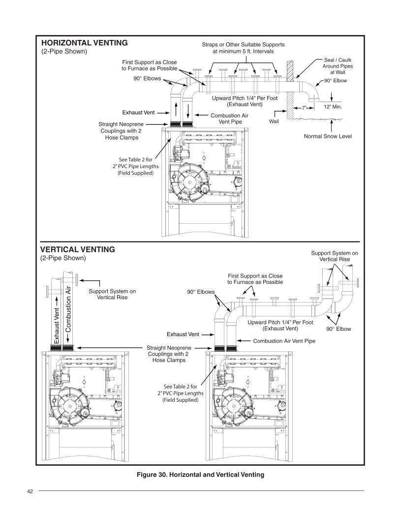
• Route piping as direct as possible between the furnace and the outdoors. Longer vent runs require larger diameters. Vent piping must be sloped upwards 1/4” per foot in the direction from the furnace to the terminal. This ensures that any condensate fl ows back to the condensate disposal system.
• If a Direct Vent (2-pipe) system is used, the combustion air intake and the vent exhaust must be located in the same atmospheric pressure zone. This means both pipes must exit the building through the same portion of exterior wall or roof as shown in Figure 30, page 42.
• Piping must be mechanically supported so that its weight does not bear on the furnace. Pipe supports must be installed a minimum of every fi ve feet along the vent run to ensure no displacement after installation. Supports may be at shorter intervals if necessary to ensure that there are no sagging sections that can trap condensate. It is recommended to install couplings along the vent pipe, on either side of the exterior wall (Figure 30). These couplings may be required by local code.
• If breakable connections are required in the combustion air inlet pipe (if present) and exhaust vent piping, then
straight neoprene couplings for 2” or 3” piping with hose clamps can be used. These couplings can be ordered through your local furnace distributor. To install a coupling:
1. Slide the rubber coupling over the end of the pipe that is attached to the furnace and secure it with one of the hose clamps.
2. Slide the other end of the rubber coupling onto the other pipe from the vent.
3. Secure the coupling with the second hose clamp, ensuring that the connection is tight and leak free.
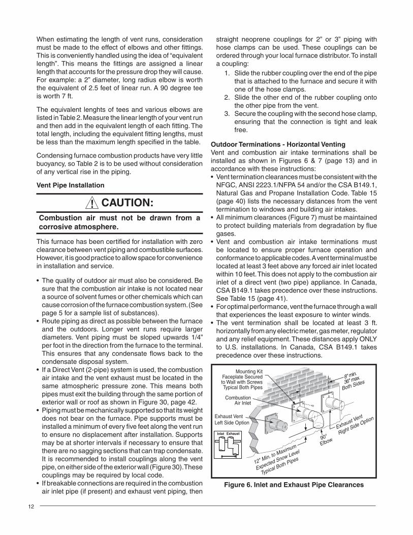
Outdoor Terminations - Horizontal VentingVent and combustion air intake terminations shall be installed as shown in Figures 6 & 7 (page 13) and in accordance with these instructions:• Vent termination clearances must be consistent with the
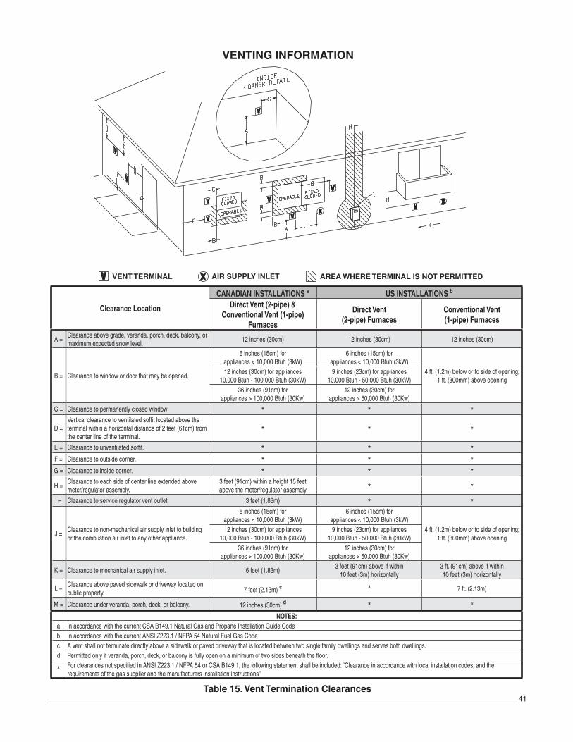
NFGC, ANSI 2223.1/NFPA 54 and/or the CSA B149.1, Natural Gas and Propane Installation Code. Table 15 (page 40) lists the necessary distances from the vent termination to windows and building air intakes.
• All minimum clearances (Figure 7) must be maintained to protect building materials from degradation by fl ue gases.
• Vent and combustion air intake terminations must be located to ensure proper furnace operation and conformance to applicable codes. A vent terminal must be located at least 3 feet above any forced air inlet located within 10 feet. This does not apply to the combustion air inlet of a direct vent (two pipe) appliance. In Canada, CSA B149.1 takes precedence over these instructions. See Table 15 (page 41).
• For optimal performance, vent the furnace through a wall that experiences the least exposure to winter winds.
• The vent termination shall be located at least 3 ft. horizontally from any electric meter, gas meter, regulator and any relief equipment. These distances apply ONLY to U.S. installations. In Canada, CSA B149.1 takes precedence over these instructions.
12" Min. to Maximum
Expected Snow Level
Typical Both Pipes
36" max.8" min.
Exhaust Vent
Right Side Option
Mounting KitFaceplate Securedto Wall with ScrewsTypical Both Pipes
CombustionAir Inlet
Inlet Exhaust
Both Sides
Exhaust VentLeft Side Option
90°
Elbow
Figure 6. Inlet and Exhaust Pipe Clearances
13
12 in.
12 in.
4 ft.
Note 2
Mechanicaldraft vent terminal
Direct ventterminal50,000 Btuhor less
Forced Air Inlet
Direct ventterminal - more than50,000 Btuh
Mechanical draft vent terminal
Mechanical draft vent terminal
Less
than 10 ft.
3 ft.
NOTES:1. All dimensions shown are minimum requirements.2. Exterior vent terminations must be located at least 12 In above the maximum expected snow level.
Note 2
Note 2
9 In
.
4ft.
Figure 7. Vent Locations
Support
NOTE: Vent Configuration to Provide 12" Minimumheight above Snow Level.
1/2" ArmaflexInsulation orEquivalent(if required)
12" AboveMaximumExpected
Snow Level
12" Min.19" Max.
(See Note)
Outside Wall
Figure 8. Alternate Horizontal Vent Installation
Figure 9. Vertical Vent TerminationC
ombu
stio
n A
ir
Exh
aust
Ven
t
Plumbing Vent
Roof Boot
(Typ. Both Pipes)
8" Min.
36" Max.
90° Elbow
12” Above MaximumExpected Snow Level
(Typ. Both pipes)
• Do not install the vent terminal such that exhaust is directed into window wells, stairwells, under decks or into alcoves or similar recessed areas, and do not terminate above any public walkways.
• If venting horizontally, a side wall vent kit is available according to the pipe diameter size of the installation. For 2 inch pipe use side wall vent kit #904617, and for 3 inch pipe use kit #904347. Please follow the instructions provided with the kit.
• Concentric vent termination kits are available for use with these furnaces. For 2 Inch pipe use kit #904177 and for 3 inch pipe use kit # 904176. Please follow the instructions provided with the kit.
• When the vent pipe must exit an exterior wall close to the grade or expected snow level where it is not possible to obtain clearances shown in Figure 6, a riser may be provided as shown in Figure 8. Insulation is required to prevent freezing of this section of pipe. See Table 3 for vent freezing protection.
Outdoor Terminations - Vertical Venting Termination spacing requirements from the roof and from each other are shown in Figure 9. The roof penetration must be properly fl ashed and waterproofed with a plumbing roof boot or equivalent fl ashing. Vent and combustion air piping may be installed in an existing chimney which is not in use provided that:
• Both the exhaust vent and air intake run the length of the chimney.
• The top of the chimney is sealed and weatherproofed.• The termination clearances shown in Figure 9 are
maintained.• No other gas fi red or fuel-burning equipment is vented
through the chimney.
Vent Freezing Protection• When the vent pipe is exposed to temperatures below
freezing (i.e., when it passes through unheated spaces, chimneys, etc.) the pipe must be insulated with 1/2 inch thick sponge rubber insulation, Armafl ex-type insulation or equivalent. Insulating pipe is important to avoid condensate icing.
• Table 3 lists the maximum length of fl ue pipe that can travel through an unconditioned space or an exterior space. The total vent length must not exceed the lengths noted in the Table. For Canadian installations, please refer to the Canadian Installation Code (CAN/CGA-B149.1 or 2) and/or local codes.
Winter Design Temperature
Maximum Flue Pipe Length in Unconditioned and
Exterior SpacesWithout Insulation
(feet)With Insulation
(feet)†
20 45 700 20 70
-20 10 60† Insulation thickness greater than 3/8 inch, based on an R value of 3.5 (ft x F x hr) / (BTU x in.)
Table 3. Vent Protection
14
• For extremely cold climates or for conditions of short furnace cycles (i.e. set back thermostat conditions) the last 18 inches of vent pipe can be reduced. It is acceptable to reduce from 3” to 2-1/2”, 3” to 2”, or 2” to 1-1/2” if the total vent length is at least 15 feet in length, and the vent length is within the parameters specifi ed in Table 2 (page 11). The restriction should be counted as 3 equivalent feet. Smaller vent pipes are less susceptible to freezing, but must not be excessively restrictive. The length of the 2 inch pipe must not be longer than 18 inches.
• If furnace is installed horiziontally, make sure the drainage port on the in-line drain assembly is pointed downward to ensure proper drainage of condensate. See Figure 33 - 34 on pages 43 - 46.
• To prevent debris or creatures from entering the combustion system, a protective screen may be installed over the combustion air intake opening. The screens hole size must be large enough to prevent air restriction.
Condensate DisposalThe method for disposing of condensate varies according to local codes. Consult your local code or authority having jurisdiction. Neutralizer kit P/N 902377 is available for use with this furnace. Please follow the instructions provided with the kit.
This furnace has multiple options for positioning the vent pipe as described in the section, Vent and Inducer Assembly Options. Each of the condensate drain lines must be J-trapped using fi eld supplied parts. After the condensate lines are J-trapped, they may be combined together when routed to the drain.
Existing Installations When an existing furnace is removed from a vent system serving other appliances, the existing vent system may not be sized properly to vent the remaining appliances (For example: water heater). An improperly sized venting system can result in the formation of condensate, leakage, or spillage. The existing vent system should be checked to make sure it is in compliance with NFGC and must be brought into compliance before installing the furnace.
NOTE: If replacing an existing furnace, it is possible you will encounter an existing plastic venting system that is subject to a Consumer Product Safety Commission recall. The pipes involved in the recall are High Temperature Plastic Vent (HTPV). If your venting system contains these pipes DO NOT reuse this venting system! This recall does not apply to other plastic vent pipes, such as white PVC or CPVC. Check for details on the CPSC website or call their toll-free number (800) 758-3688.
CIRCULATING AIR REQUIREMENTS
WARNING:Do not allow combustion products to enter the circulating air supply. Failure to prevent the circulation of combustion products into the living space can create potentially hazardous conditions including carbon monoxide poisoning that could result in personal injury or death.
All return ductwork must be secured to the furnace with sheet metal screws. For installations in confi ned spaces, all return ductwork must be adequately sealed. When return air is provided through the bottom of the furnace, the joint between the furnace and the return air plenum must be air tight.
The surface that the furnace is mounted on must provide sound physical support of the furnace with no gaps, cracks or sagging between the furnace and the fl oor or platform.
Return air and circulating air ductwork must not be connected to any other heat producing device such as a fi replace insert, stove, etc. This may result in fi re, explosion, carbon monoxide poisoning, personal injury, or property damage.
Plenums and Air Ducts• Plenums and air ducts must be installed in accordance
with the Standard for the Installation of Air Conditioning and Ventilating Systems (NFPA No. 90A) or the Standard for the Installation of Warm Air Heating and Air Conditioning Systems (NFPA No. 90B).
• Tables 7 - 8 (pages 34 - 36) contain the maximum airfl ow and temperature rise data for each furnace input rate. If the maximum airfl ow is 1,600 CFM or more, it is recommended that two openings be used for return air on upfl ow furnaces. Downfl ow furnaces can only use one return opening.
• It is recommended that the outlet duct contain a removable access panel. The opening should be accessible when the furnace is installed in service and shall be of a size that smoke or refl ected light may be observed inside the casing to indicate the presence of leaks in the heat exchanger. The cover for the opening shall be attached in a way that prevent leaks.
• If outside air is used as return air to the furnace for ventilation or to improve indoor air quality, the system must be designed so that the return air is not less than 60° F (15° C) during operation. If a combination of indoor
15
and outdoor air is used, the ducts and damper system must be designed so that the return air supply to the furnace is equal to the return air supply under normal, indoor return air applications.
• When a cooling system is installed which uses the furnace blower to provide airfl ow over the indoor coil, the coil must be installed downstream (on the outlet side) of the furnace or in parallel with the furnace.
• If a cooling system is installed in parallel with the furnace, a damper must be installed to prevent chilled air from entering the furnace and condensing on the heat exchanger. If a manually operated damper is installed, it must be designed so that operation of the furnace is prevented when the damper is in the cooling position and operation of the cooling system is prevented when the damper is in the heating position.
• It is good practice to seal all connections and joints with industrial grade sealing tape or liquid sealant. Requirements for sealing ductwork vary from region to region. Consult with local codes for requirements specifi c to your area.
Supply Air ConnectionsThe supply air must be delivered to the heated space by duct(s) secured to the furnace casing, running full size and without interruption.
Upfl ow and Horizontal FurnacesTo attach the supply air duct to the furnace, bend the furnace fl anges (Figure 28, page 33) upward 90° with a pair of wide duct pliers. Position the duct on top of the furnace and secure together with sheet metal screws. The screws must penetrate the sheet metal casing and furnace fl ange. Tape or seal all seams if required by local code.
Downfl ow FurnacesTo attach the supply air duct to the downfl ow furnace, position the furnace over the duct and secure together with sheet metal screws. The screws must penetrate the duct and furnace cabinet.
Return Air ConnectionsIn applications where the supply ducts carry heated air to areas outside the space where the furnace is installed, the return air must be delivered to the furnace by duct(s) secured to the furnace casing, running full size and without interruption. It is good practice to seal all connections and joints with industrial grade sealing tape or liquid sealant. Requirements for sealing ductwork vary from region to region. Consult with local codes for requirements specifi c to your area.
Upfl ow Horizontal FurnacesFor upfl ow installations, the return air ductwork may be connected to the left side, right side, or bottom. The bottom panel (Figure 28) must be installed for left or right return air. NOTE: Do not use the back of the furnace for return air.
Side Return InstallationsTo attach the return air duct to the left or right side of the furnace, punch out the four knockouts (Figure 28) from the preferred side of the furnace. Using sharp metal cutters, cut an opening between all four knockouts to expose the blower assembly. Position the return air duct over the opening in the side and secure together with sheet metal screws. The screws must penetrate the duct and furnace cabinet.
WARNING:The solid base of the furnace must be in position when the furnace is installed with side return air ducts. Removal of all or part of the base could cause circulation of combustible products into the living space and create potentially hazardous conditions, including carbon monoxide poisoning that could result in personal injury or death.
Bottom Return InstallationsThe bottom panel (Figure 28) must be removed from the furnace for bottom return air. If bottom panel is installed, go to page 16 for removal instructions. Position the furnace over the return air duct and secure together with sheet metal screws. The screws must penetrate the duct and furnace cabinet.
Downfl ow FurnacesTo attach the return air duct to the furnace, bend the furnace fl anges (Figure 28) upward 90° with a pair of wide duct pliers. Position the duct on top of the furnace and secure together with sheet metal screws. The screws must penetrate the sheet metal cabinet and furnace fl ange. Tape or seal all seams if required by local code.
Acoustical TreatmentsDamping ducts, fl exible vibration isolators, or pleated media-style fi lters on the return air inlet of the furnace may be used to reduce the transmission of equipment noise eminating from the furnace. These treatments can produce a quieter installation, particularly in the heated space. However, they can increase the pressure drop in the duct system. Care must be taken to maintain the proper maximum pressure rise across the furnace, temperature rise and fl ow rate. This may mean increasing the duct size and/or reducing the blower speed. These treatments must be constructed and installed in accordance with NFPA and SMACNA construction standards. Consult with local codes for special requirements. For best sound performance, install all the needed gaskets and grommets around penetrations into the furnace, such as for electrical wiring.
16
FURNACE INSTALLATION *SC series gas furnaces offer a wide range of installation options, including installation in the upfl ow or horizontal positions with either right, left, or upfl ow return air. The *SL series gas furnaces may only be installed as a down fl ow application.
General Requirements• The furnace must be leveled at installation and attached
to a properly installed duct system. See Table 1 (page 7) for the required clearances needed to move the furnace to its installation point (hallways, doorways, stairs, etc).
• The furnace must be installed so that all electrical components are protected from water.
• The furnace must be installed upstream from a refrigeration system. (If applicable)
• The cabinet plug must always be used to close the hole in the side of the furnace when rotating the inducer.
• The furnace requires special venting materials and installation procedures. See pages 10 -14 for venting guidelines and specifi cations.
Direct Vent (2-Pipe) ApplicationsIt is important that Direct Vent (2-pipe) systems maintain an airtight fl ow path from the air inlet to the fl ue gas outlet. The furnace ships from the factory with two holes in the cabinet for the air inlet and fl ue gas outlet. In certain confi gurations, it is necessary to remove and relocate a plastic cap in the furnace cabinet. If changing the position of the air inlet and fl ue gas outlet, it is required that the previous hole be closed off with the plastic cap to maintain air tightness in the furnace. The hole locations for *SC and *SL furnaces are indicated in Figure 28 (page 33).
Upfl ow Installation
WARNING:The furnace must not be installed directly on carpeting, tile, or any combustible material other than wood fl ooring.
Side Return Air Inlet*SC series gas furnaces are shipped with the bottom panel installed (Figure 28). If the furnace is installed using both side return air inlets, the bottom panel must not be removed. If the bottom of the furnace is not being used as a return, leave the bottom panel in place.
Bottom Return Air InletIf the *SC series gas furnace is installed using the bottom as a return air inlet and 1 side return, the bottom panel (Figure 28) must be removed. See Bottom Panel Removal on page 18.
Downfl ow Installation
WARNING:The furnace must not be installed directly on carpeting, tile, or any combustible material other than wood fl ooring.
WARNING:Failure to install the downfl ow sub-base kit may result in fi re, property damage or personal injury.
To install the furnace on combustible fl ooring, a special sub-base is required. Downfl ow sub-base kits are factory supplied accessories and are listed according to the cabinet letter of the furnace. For ‘A’ size cabinets use Sub-Base kit #902974 only. For ‘B’, ‘C’, and ‘D’ size cabinets use Kit #904911. Please follow the instructions provided with the kit.
A downfl ow sub-base kit is not necessary if the furnace is installed on a factory or site-built cased air conditioning coil. However, the plenum attached to the coil casing must be installed so that its surfaces are at least 1” from combustible construction.
Installation on a concrete slab.1. Create an opening in the fl oor according to the
dimensions in Figure 10.2. Position the plenum and the furnace as shown in
Figure 11 (page 17).
*SL MODEL Number’s:
Dimension “A”
Dimension“B”
054D-24B 16 5/8 19 1/4
072D-24B 16 5/8 19 1/4
090D-35C 20 1/8 19 1/4
120D-45D 23 5/8 19 1/4
Dimensions shown in Inches.
“A”
“B”
Opening in concrete floor
Figure 10. Cutout Dimensions
17
Horizontal Installation
WARNING:The furnace must not be installed directly on carpeting, tile, or any combustible material other than wood fl ooring.
The *SC series gas furnace can be installed horizontally (Figure 12) in an attic, basement, crawl space or alcove. It can also be suspended from a ceiling in a basement or utility room in either a right to left airfl ow or left to right airfl ow as shown in Figure 14 (page 18).
*SC series furnaces are shipped with the bottom panel installed. If the furnace is installed horizontally, remove the bottom panel from the furnace before attaching the duct system. See Bottom Panel Removal on page 18.
If the furnace is to be installed in an attic, it is required that a drip pan be placed under the furnace. If the installation is on a combustible platform (Figure 12), it is recommended that the drip pan extend at least 12 inches past the top and front of the furnace.
If the furnace will be suspended from the ceiling, as-semble a support frame (Figure 14) using slotted iron
Figure 12. *SC Horizontal installation on a Platform
Exhaust PipeVented to Outside
CombustiblePlatform
Coil Plenum
Electrical SupplyConnection
Combustion Air
Condensate Drain Lines Must Be Trapped With J-Trap or Field Supplied Loop.One-Pipe Installation Shown
PVC TEE
Figure 11. Furnace on a Concrete Slab
Concrete Floor
Furnace
Sheet Metal
Plenum3
1
Special Instructions for SC038-23A FurnacesIf furnace is to be installed horizontally with airfl ow going from left to right, the pressure switch will need to be moved to the side of the furnace that is not facing the ground (Figure 13). Moving the switch will make it easier to replace in the future.
1. Shut off any electrical power to the furnace.2. Label and disconnect the tubing and wires from the
pressure switch (1).3. Remove two screws (2) securing the pressure switch
(1) to the side of the furnace.4. Remove two 1/4” black plugs (3) on the opposite
side of the cabinet that the pressure switch will be relocated to.
5. Position the pressure switch (1) in its new location and secure it in place using the same screws (2) removed in step 2
6. Insert the plugs (3) into the holes on the side that the pressure switch (1) was removed from.
7. Reconnect the tubing and wiring to the pressure switch (1) being careful that they will not fall into the burner box.
CAUTION:It is extremely important that all wires and tubes be correctly reattached to the pressure switch(s). Failure to do so will result in malfunction or compromised safety functions of the furnace.
8. Check the furnace for proper operation as directed in Startup and Adjustments section. If the furnace shuts down during the pre-purge, the switch that measures pressure in the header needs to be checked for correct tubing connections.
Figure 13. SC038-23A Pressure Switch
2
18
67
5
12
3
4
Figure 15. Bottom Panel Removal
Figure 16. Alternate Removal Method
1
4
2
7
3
6
5
Figure 14. *SC Horizontally Suspended in Attic or Crawl Space
LagBolt
Nuts (x2)
Washer and
Lockwasher
Nuts (x2)
Threaded Rod
channel and full threaded rod. Fasten the frame together with nuts, washers, and lockwashers. Secure the support frame to the rafters with lag bolts. The furnace can also be suspended using steel straps around each end of the furnace. The straps should be attached to the furnace with sheet metal screws and to the rafters with bolts.
It is recommended for further reduction of fi re hazard that cement board or sheet metal be placed between the furnace and the combustible fl oor and extend 12 inches beyond the front of the door and top of the furnace.
Bottom Panel RemovalThe steps listed below describe how to remove the bottom panel from the furnace. See Figure 15.1. Remove the door (1) from the blower compartment.2. Disconnect the blower motor wiring harness (2) from
the control board.3. Remove two screws (3) securing the blower assembly
(4) to the furnace.4. Carefully pull the blower assembly (4) out thru the
front of the furnace.
5. Remove all screws (5) securing bottom panel (6) to bottom of furnace and front brace (7).
6. Lift up and slide bottom panel (6) out through front of furnace.
7. Reinstall the blower assembly (4) in reverse order.
Alternate Bottom Panel RemovalIf the bottom panel cannot be removed using the previous instructions, the steps below are an alternate method for removing the bottom panel. (See Figure 16).
1. Remove the door (1) from the blower compartment2. Remove all screws securing the bottom panel (2) to
the front brace (3).3. Remove two screws (4) securing the furnace cabinet
to the blower deck (5).4. Remove all screws (6) securing the furnace cabinet
to the bottom panel (2).5. Remove the screw (7) securing the bottom corner of the
furnace cabinet to the front brace (3).6. Carefully spread the bottom corner of the furnace
cabinet outwards while sliding the bottom panel (2) out through the front of the furnace.
7. Reassemble the furnace in reverse order.
19
Inducer Assembly Rotation
WARNING:Inducer rotation must be completed before the furnace is connected to gas and electric. If both utilities have been connected, follow the shutdown procedures printed on the furnace label and disconnect the electrical supply.
CAUTION:It is good practice to label all wires prior to disconnection. Wiring errors can cause improper and dangerous operation.
1. Disconnect the electrical harness (1) from the inducer assembly (2) as shown in Figure 17.
2. Remove the inducer assembly ground wire (3) from the blower deck (4) or door.
3. Remove three screws (5) securing the inducer assembly (2) to the header box (6).
4. Rotate the inducer assembly (2) to its new position.5. Secure the inducer assembly (2) to the header box
(6) by reinstalling the three screws (5). If the inducer assembly is rotated to the left or right side of the furnace, use the extra screw provided in the parts package.
6. Remove the cabinet plug (7) from side of furnace and reinstall in hole on opposite side of cabinet.
7. Install in-line drain assembly and tubing.8. If applicable, install the condensate drain lines as
shown in (Figures 31 - 34, pages 43 - 46).9. Reconnect the electrical harness (1) to the inducer
assembly (2).10. Reconnect the inducer assembly ground wire (3) to
the blower deck (4) or door.11. Verify operation as detailed on the furnace label.
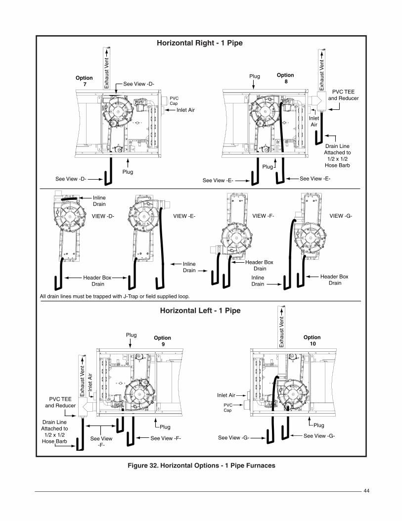
Vent and Inducer Assembly OptionsTo increase installation fl exibility, the inducer assembly can be rotated up to 3 different positions. Each variation has slightly different requirements with regard to condensate disposal and, in some cases, the need to seal the furnace cabinet. IMPORTANT NOTE: The Inducer Assembly must never be positioned to vent downwards on horizontal installs.
Before using Table 4, the number of pipes (1-pipe or 2-pipe) connected to the furnace must be known. Find the proper furnace style (upfl ow, horizontal, or downfl ow) and then the side that the pipes will exit from the furnace. Finally select the option that properly matches your installation type from Figures 31 - 34.
Figure 17. Inducer Assembly Rotation
RC
YG
W
STATUS
FLAME
180
CO
OL
HE
AT
1209060
BLOWEROFF
DELAY
LO
WML
MH
HIG
HE
ACL1
XF
MR
HU
M
24V
L1A
NE
UT
RA
LS
2
789
2
FAN
2
5
1 3
6
4
Table 4. Vent and Inducer Blower Options
Conventional (1 Pipe)
Vent Upfl owHorizontal
RightHorizontal
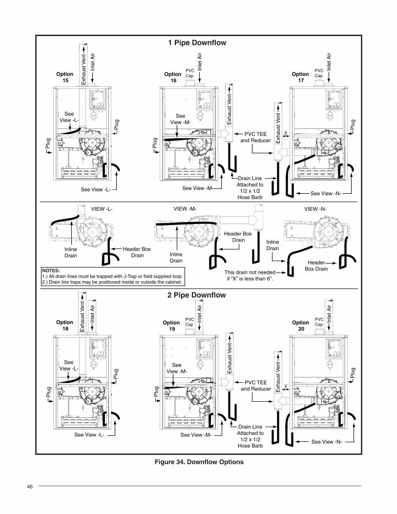
LeftDownfl ow
Up Option 1 Option 7 Option 10 Option 15
Right Option 2 Option 8 N/A Option 16
Left Option 3 N/A Option 9 Option 17
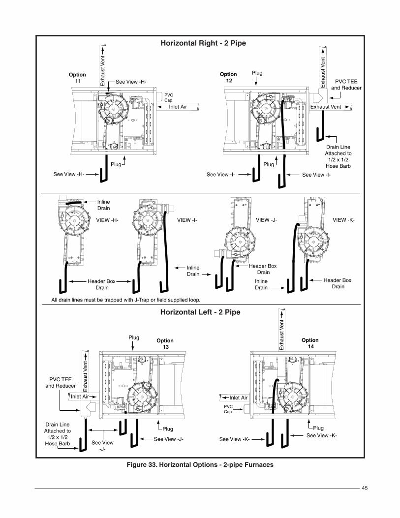
Direct Vent (2-pipe)
Vent Upfl owHorizontal
RightHorizontal
LeftDownfl ow
Up Option 4 Option 12† Option 14† Option 18
Right Option 5† Option 11 N/A Option 19†
Left Option 6† N/A Option 13 Option 20†
† Requires a 2 inch PVC endcap.
Pressure Switch RelocationIn some inducer orientations, the inducer pressure switch may interfere with gas pipe installation. Determine the side of the cabinet the gas pipe will enter and see if the inducer pressure switch needs to be moved. If the pressure switch interferes with the gas pipe, please follow these instructions for relocating it to the alternate location:1. Shut off any electrical power to the furnace.2. Label and disconnect the tubing and wires from the
pressure switch (Figure 18, page 20).3. Remove two screws securing the pressure switch to
the inducer housing.4. Remove the pressure switch from the mounts on the
inducer housing and relocate it to the other set of mounts 90° from previous location.
5. Secure the pressure switch with two screws.6. Reconnect the tubes and wires to the pressure switch.
20
Figure 18. Alternate Pressure Switch Location
PRIMARYLOCATION
ALTERNATELOCATION
AccessoriesThe components below are included in the extra parts bag that is supplied with the purchase of your furnace. Depending on your particular installation, some of these components are optional and may not be used. Please refer to the descriptions and accompanying fi gures when installing these items.
Finish Flanges (Fig. 19)The fi nish fl anges must be installed to vent the combustion air pipe through the top of the furnace. NOTE: For proper installation it is important that the pipe and screw holes in the fi nish fl anges, gasket, and cabinet are alignes.
1. Position fl ange gasket over hole in the furnace cabinet.
2. Position fi nish fl ange on top of the fl ange gasket.3. Secure fl ange and gasket to cabinet with three fi eld
supplied sheet metal screws.4. Repeat steps 1 - 3 for other vent hole.
Rubber Grommets (Fig. 20)The 2 1/4” rubber grommet is used to seal the opening between the furnace cabinet and the 2” PVC vent pipe. The rubber grommet should be installed in the 3” hole prior to running the vent pipe out of cabinet. No sealants are required.
The 7/8” rubber grommet is used to seal the opening between the furnace cabinet and the gas pipe. The rubber grommet should be installed in the 1 5/8” hole prior to running the gas pipe into the cabinet. No sealants are required.
The 3/4” rubber grommet is used if venting out the left side of the cabinet and the drain tube is routed through the blower deck. Remove the plastic plug from the hole and install the grommet before routing the drain tube.
Finish Flange
Finish Flange
Flange Gasket
Flange Gasket
Hole for Flue Vent Pipe Hole for Inlet
Air Vent Pipe
Figure 19. Finish Flanges
Ø 3/4” RubberGrommet
ø 2 1/4” RubberGrommet
ø 7/8” RubberGrommet
Figure 20. Rubber Grommets
PVC TEE, Reducer, and Hose Barbs (Fig. 21)
IMPORTANT NOTES:Before permanently installing these components, it is recommended you dry-fi t them fi rst to ensure proper fi t and alignment with other vent pipes.
The PVC items shown in Figure 21 are not provided in the extra parts bag.
The 2” PVC tee, reducer, and hose barb are used when the inducer is rotated to vent out thru the left or right side of the furnace cabinet.
The 1/2” x 3/4” hose barb can be used to route the condensate drain to the outside of the cabinet. It must be installed from inside the cabinet with the threaded end inserted thru the 1 1/16” hole. See Figure 28 (page 33) for hole location. The Condensate drain should be connected to the barbed end. Attach 1” PVC drain line to the threaded end.
1. Install the 1/2” x 1/2” hose barb on the 2” PVC reducer. Do not over tighten! NOTE: Use an adequate amount of Tefl on tape on the threads. Do not use liquid sealants.
21
2” PVC TEE
2” x 1/2” PVC Reducer
1/2” x 1/2” Hose Barb
1/2” x 3/4” Hose Barb
2” PVC Pipe from Inline Drain Assembly
(Not Included)
Figure 21. 2” PVC Tee, Reducer and Hose Barb
2. Install the reducer on one end of the PVC tee. Use appropriate primer and cement to permanently bond the reducer and tee together.
3. Install the tee on the 2” vent pipe that is extending out the side of the cabinet. Use appropriate primer and cement to permanently bond them together.
4. Verify all connections and joints for tight fi t and proper alignment with other vent pipes.
Figure 22. Optional PVC Pipe Installation
2” x 450 PVCElbow
2” PVC Pipe
2” x 3” PVCCoupling
Coil Box
Optional PVC Pipe Installation (Figure 22)When running the 2” PVC pipe out through the top of the *SC upfl ow furnace, there may be possible clearance issues when transitioning the PVC pipe from 2” to 3”:
• If you have to increase the size of the PVC fl ue from 2” to 3”, you may use two, 2” x 45° PVC elbows to achieve the clearances needed between the coil box and the 2” x 3” coupling.
• Install the 2” x 3” coupling in the vertical run only. If the coupling is installed horizontally, it will allow water to build up inside the furnace and cause a lock out condition.
• To avoid the clearance issue, it is recommended that the furnace be vented through the left side or the right side of the cabinet as shown in Figures 31 - 34.
Condensate Drain LinesThe placement of the condensate drain lines will depend on the confi guration selected in Table 4 (page 19). The drain lines can be routed out the left or right side of the furnace, but must maintain a downward slope to ensure proper condensate drainage. The J-trap may need to be rotated to the side that matches your setup in Figures 31 - 34 (pages 42 - 45). To rotate the J-trap, loosen the clamp on the drain tube, rotate the J-trap to either side, and retighten the clamp
Four general principles apply:• Each condensate drain must be trapped separately
using a J-Trap or fi eld supplied loop.• There must always be a drain attached to the collector
at the outlet of the secondary heat exchanger.• There must always be a drain at the outlet of the inducer
assembly.• There must always be a drain at the lowest point of the
venting system.
Exceptions and clarifi cations to the general rules:• In some cases, the lowest point in the vent system is
where it connects to the inducer. Options 8, 10, 12, & 14. In this case one drain at this location is suffi cient.
• If the vent exits the furnace horizontally, the vent may be turned vertically with a tee. The drip leg formed by the tee must include a drain. Options 2,3,5,6,8,9,12,13,16,17,19, & 20.
• In certain cases, it is permitted to drain the inducer back into the top drain of the collector. This drain must not sag in the middle. Options 2, 5, 7, 11, 15, 16, 18 & 19.
IMPORTANT NOTE: If the furnace is installed in an area where temperatures fall below freezing, special precautions must be made for insulating condensate drain lines that drain to the outdoors. If condensate freezes in the lines, this will cause improper operation or damage to the furnace. It is recommended that all drain lines on the outside of the residence be wrapped with an industry approved insulation or material allowed by local code.
22
GAS SUPPLY AND PIPINGAll gas piping must be installed in compliance with local codes and utility regulations. In the absence of local codes the gas line installation must comply with the latest edition of the National Fuel Gas Code (ANSI Z223.1) or (CAN/CGA B149.1 or .2) Installation Codes.
IMPORTANT NOTES:• Some local regulations require the installation of a
manual main shut-off valve and ground joint union external to the furnace See Figure 23 (page 23). The shut-off valve should be readily accessible for service and/or emergency use. Consult the local utility or gas supplier for additional requirements regarding placement of the manual main gas shut-off.
• Gas piping must never run in or through air ducts, chimneys, gas vents, or elevator shafts.
• Compounds used on threaded joints of gas piping must be resistant to the actions of liquefied petroleum gases.
• The main gas valve and main power disconnect to the furnace must be properly labeled by the installer in case emergency shutdown is required.
• Flexible gas connectors are not recommended for this type of furnace but may be used if allowed by local jurisdiction. Only new fl exible connectors may be used. Do not reuse old fl exible gas connectors.
• A drip leg should be installed in the vertical pipe run to the unit (Figure 23).
Table 10 (page 38) lists gas fl ow capacities for standard pipe sizes as a function of length in typical applications based on nominal pressure drop in the line.
The furnace may be installed with either left or right side gas entry. When connecting the gas supply, provide clearance between the gas supply line and the entry hole in the furnace casing to avoid unwanted noise and/or damage to the furnace. Typical gas hookups are shown in Figure 23.
Leak Check
WARNING:FIRE OR EXPLOSION HAZARD
Never test for gas leaks with an open fl ame. Check all connections using a commercially available soap solution. A fi re or explosion may result causing property damage, personal injury or loss of life. Failure to follow the safety warnings exactly could result in serious injury, death or property damage.
After the gas piping to the furnace is complete, all connections must be tested for gas leaks. This includes pipe connections at the main gas valve, emergency shutoff valve and fl exible gas connectors (if applicable). The soap and water solution can be applied on each joint or union using a small paintbrush. If any bubbling is observed, the connection is not sealed adequately and must be retightened. Repeat the tightening and soap check process until bubbling ceases.
IMPORTANT NOTE: When pressure testing gas supply lines at pressures greater than 1/2 psig (14 inch W.C.), the gas supply piping system must be disconnected from the furnace to prevent damage to the gas control valve. If the test pressure is less than or equal to 1/2 psig (14 inch W.C.), close the manual shut-off valve.
High Altitude ApplicationHigh altitude conversion with this furnace depends on the installation altitude and the heating value of the gas. The installation of this furnace at altitudes above 2,000 feet must meet the requirements of the National Fuel Gas Code or local jurisdiction. In Canada, the requirements for high altitude are different and governed by CGA B149.1. Please consult your local code authority.
WARNING:The reduction of input rating necessary for high altitude installation may only be accomplished with factory supplied orifi ces. Do not attempt to drill out orifi ces in the fi eld. Improperly drilled orifi ces may cause fi re, explosion, carbon monoxide poisoning, personal injury or death.
The furnaces are shipped from the factory with orifi ces and gas regulator settings for natural gas operation at sea level altitudes. At 2000 feet, the NFGC requires that this appliance be derated 4% for each 1000 feet of altitude. For example, the input needs to be reduced 8% at 2,000 feet, 12% at 3,000 feet, etc. This deration is in reference to the input rate and gas heating value at sea level.
To derate the furnace requires knowing the heating value of the gas at the installation site. Heating values at particular job sites vary for two reasons:
1. The chemical mixture of the gas varies from region to region and is expressed as the “sea level heating value”.
2. The heating value varies by altitude. For this reason, especially in high altitude areas, the local gas utility specifi es the heating value at the residence’s gas meter as the “local value”.
NOTE A: Some utilities require Shut- Off Valve to be 4 to 5 feet above fl oor.NOTE B: Inducer assembly omitted for clarity of pipe installation.
Figure 23. Typical Gas Connections
6
4
2
UPFLOW MODELS
DOWNFLOW MODELS
1
See Note “B”7See
Note “B”
Right Side EntryLeft Side Entry
Right Side EntryLeft Side Entry
See Note “B”
See Note “B”
1
7
4
3
99
3
See Note “A”
See Note “A”
55
4
7
1
2 6 6
7
2
See Note “A”
See Note “A”
8
2
4
3
9
5
8
9
3
5
6 2
24
INSTALLATION EXAMPLE
Elevation: ................................................5,000 feetType of Gas: .........................................Natural GasLocal Heating Value of Gas: ............................750
Determine which natural gas table to use. From Table 12, fi nd 750 and follow down the column, stop at the 5,000 feet row. The heating value listed is LOW. Table 14 will be used to determine orifi ce size and manifold pressure.
For added fl exibility, two tables have been provided for natural gas installations with high or low heating values at sea level. Tables 13 and 14 (page 40) contain the manifold pressure and orifi ce sizes to use at various altitudes. Table 13 (HIGH) is for natural gas installations with a heating value of more than 1,000 Btu per cubic foot and Table 14 (LOW) is for less than 1,000 Btu per cubic foot. To determine which table to use:
1. Consult the local utility for the local heating value at your installation site.
2. From Table 12 (page 39), fi nd your local heating value as supplied by the utility company. Follow down the column and stop at your altitude level.
3. If your sea level heating value is HIGH, use Table 13 or if it’s LOW, use Table 14. (See example below.)
After changing the regulator pressure or the orifi ces, it is required that you measure the gas input rate. This may be accomplished in the usual way, by clocking the gas meter and using the local gas heating value. See Verifying and Adjusting the Input Rate section (page 27).
IMPORTANT NOTE: Observe the action of the burners to make sure there is no yellowing, lifting or fl ashback of the fl ame.
Conversion to LP/Propane
WARNING:The furnace was shipped from the factory equipped to operate on natural gas. Conversion to LP/propane gas must be performed by qualifi ed service personnel using a factory supplied conversion kit. Failure to use the proper conversion kit can cause fi re, explosion, property damage, carbon monoxide poisoning, personal injury, or death.
Conversion to LP/propane is detailed in the installation instructions provided with the conversion kit. Generally, this will require the replacement of the burner orifi ces and the spring found under the cap screw on the pressure regulator.
In the U.S. if installation is above 2,000 ft., refer to Table 11 (page 39) to determine the correct orifi ce size and regulator pressure. When conversion is complete, verify the manifold pressure and input rate are correct as listed in the tables. Approved conversion kits are listed below:
• The United States LP/Propane Gas Sea Level and High Altitude Conversion Kit (P/N 904914) is for LP/propane conversion in the United States at altitudes between 2,000 ft. and 10,000 ft. above sea level. Please follow the instructions provided with the kit.
• The Canadian LP/Propane Gas Sea Level and High Altitude Conversion Kit (P/N 904915) is for LP/propane conversions in Canada at altitudes between zero and 4,500 ft. above sea level. Please follow the instructions provided with the kit.
ELECTRICAL WIRING
WARNING:To avoid electric shock, personal injury, or death, turn off the electric power at the disconnect or the main service panel before making any electrical connections.
• Electrical connections must be in compliance with all applicable local codes with the current revision of the National Electric Code (ANSI/NFPA 70).
• For Canadian installations the electrical connections and grounding shall comply with the current Canadian Electrical Code (CSA C22.1 and/or local codes).
CAUTION:Label all wires prior to disconnection when servicing controls. Wiring errors can cause improper and dangerous operation. Verify proper operation after servicing.
IMPORTANT NOTE: If replacing any of the original wires supplied with the furnace, the replacement wire must be copper wiring and have a temperature rating of at least 105°F (40°C). For electrical specifi cations, refer to the furnace nameplate or Table 5 (page 25).
Line Voltage WiringIt is recommended that the line voltage (115 VAC) to the furnace be supplied from a dedicated branch circuit containing the correct fuse or circuit breaker for the furnace as listed in Table 5.
IMPORTANT NOTES:An electrical disconnect must be installed readily accessible from and located within sight of the furnace. See Figure 24 (page 25) or the wiring diagram label inside of the control door. Any other wiring methods must be acceptable to authority having jurisdiction.
25
Proper line voltage polarity must be maintained in order for the control system to operate correctly. Verify the incoming neutral line is connected to the white wire and the incoming “hot” line is connected to the black wire. The furnace will not operate unless the polarity and ground are properly connected as shown in Figure 24.
Low Voltage WiringThe thermostat must be installed according to the instructions supplied by the thermostat manufacturer. Low voltage connections (24 VAC) from the thermostat are wired to the terminal strip on the integrated control in the furnace. Figure 25 (page 26) contains the proper connections for heating only (two-wire) and heating/cooling (four-wire) applications. Recommended minimum wire gauge for thermostat wiring is shown in Table 5.
The thermostat must not be installed on an outside wall or any other location where its operation may be adversely affected by radiant heat from fi replaces, sunlight, or lighting fi xtures, and convective heat from warm air registers or electrical appliances.
IMPORTANT NOTE: Set the heat anticipator according to the instructions supplied by the thermostat manufacturer.
To determine the heat anticipator setting:
1. Add the current draw of the system components; or2. Measure the current fl ow on the thermostat R-W circuit
after the circulating blower motor has started.
Figure 24. Line Voltage Field Wiring
Field Supplied Disconnect w/in Sight of Furnace
Field SuppliedPanel Connector
Field SuppliedFused Service
Panel
Black (Hot)
White (Neutral)
Green or Bare(Ground)
Black
White
Black
White
Black
White
Field Line Voltage Wiring
Factory Line Voltage Wiring
Ground Ground
Junction Box (may be int. or ext.to the furnace). These connectionscan be made in the field supplieddisconnect at the furnace.
Ground
FurnaceModel Number
*SC/*SL
FurnaceInput(Btuh)
CabinetWidth(in.)
NominalElectrical
Supply
MaximumOperating
Voltage
MinimumOperating
Voltage
MaximumFurnaceAmperes
MinimumWire
Gauge
MaximumFuse or CircuitBreaker Amps†
038D-23A 38,000 14 ¼ 115-60-1 127 103 6.6 14 15
054D-24B 54,000 17 ½ 115-60-1 127 103 10.0 14 20
072D-24B 72,000 17 ½ 115-60-1 127 103 10.0 14 20
072D-35C 72,000 21 115-60-1 127 103 9.3 14 15
090D-35C 90,000 21 115-60-1 127 103 15.6 14 30
108D-45D 108,000 24 ½ 115-60-1 127 103 15.6 14 30
120D-45D 120,000 24 ½ 115-60-1 127 103 15.6 12 30† Time-delay fuses or HACR-type circuit breakers are required.
Figure 25. Low Voltage Field, Four-wireHeating/Cooling Applications
RC
YG
W
STATUS
FLAMEGREENRED
180
CO
OL
HE
AT
1209060
YELLOW
BLOWEROFF
DELAY
LO
WML
MH
HIG
HE
ACL1
XF
MR
HU
M
CO
M SPEEDSELECT
3 AMPFUSE
24V
5
NE
UT
RA
LS
ROOMTHERMOSTAT
A/C CONDENSING UNIT
CONDENSING UNITCONTROL BOX
EXPANSION PORT(MOTOR CONNECTION)
FIELD WIRINGLOW VOLTAGECONNECTION
RCYGW
NOTE: The “Y” terminal on the control board must be connected to the thermostat for proper cooling mode operation.
ConnectR & W
For Heating Only
2
ELECTRONIC AIR CLEANER
MOTOR SPEED TAPS (NOT USED)
HUMIDIFIER TAP
NEUTRAL LEADS
6 3
4 1
789
5 26 3
4 1
FAN
The six pin terminal marked “Expansion Port” is not used in the single stage furnace as shipped from the factory. It is used for the furnace control board to communicate to a fi xed speed or variable speed high effi ciency motor that may be optionally installed. Please contact your distributor for the proper upgrade motor kit.
Grounding
WARNING:To minimize personal injury, the furnace cabinet must have an uninterrupted or unbroken electrical ground. The controls used in this furnace require an earth ground to operate properly. Acceptable methods include electrical wire or conduit approved for ground service. Do not use gas piping as an electrical ground!
TwinningSingle stage G7 furnaces are not supplied with a built-in twinning capability. Other valuable features and enhancements were made to the new control that made it necessary to remove the twinning capability. All standard two-stage furnaces equipped with the fi xed speed iSEER™ motor include a twinning terminal on the blower control board.
However, if both single stage G7 furnaces are upgraded to the fi xed speed iSEER ™ blower, the twin terminal on the blower control boards (Figure 26) may be used to twin the single stage furnaces only if the following criteria are met:• Both furnaces and motors must be the same size.
• Both motors must be on the same speed for cooling and heating.
• Both furnaces must have a common return duct and common supply plenum.
• Both furnaces must be on the same leg of power.
IMPORTANT NOTE: G7 furnaces equipped with variable speed iSEER ™ motors may not be twinned under any circumstances.
Please contact your furnace distributor for technical details.
FURNACE
WGYCR
THERMOSTAT
W G Y R
A/C
FSHE
TWIN TERMINAL
BOARD
UNIT
BOARD
FURNACEBOARD
FSHE
TWIN TERMINAL
BOARD
FURNACE 1 FURNACE 2
WGYCR
Figure 26. Single Stage Twinning
27
START-UP AND ADJUSTMENTSPre-Start Check List
√ Verify the polarity of the connections are correct, the line voltage power leads are securely connected and the furnace is properly grounded.
√ Verify the thermostat wires (R, W, Y, and G) are securely connected to the correct leads on the terminal strip of the circuit board.
√ Verify the gas line service pressure does not exceed 10.0 inches of W.C., and is not less than 4.5 inches W.C. for natural gas. For LP gas the line service pres-sure must not exceed 14 in. W.C., and must not be less than 11.0 in. W.C.
√ Verify the roll-out and manual reset switch is closed. If necessary, press the red button to reset a switch. DO NOT install a jumper wire across a switch to defeat its function. If a switch reopens on startup, DO NOT reset the switch without identifying and correcting the fault condition.
√ Verify the blower door is in place, closing the door switch in the line voltage circuit.
√ Verify the gas line has been purged and all connections are leak free.
Start-up ProceduresDo not perform these steps until all of the checks in the previous steps have been completed:1. Set the thermostat to the lowest setting.2. Turn off all electrical power to the furnace.3. Follow the Operating Instructions on the label attached
to the furnace.4. Set the thermostat above room temperature and verify
the Operating Sequence (page 28).5. After 5 minutes of operation, set the thermostat
below room temperature and verify steps 9 - 10 of the Operating Sequence.
Verifying and Adjusting Input Rate
IMPORTANT NOTE: The input rate must not exceed the rate shown on the furnace rating plate. At altitudes above 2,000 feet, it must not exceed that on the rating plate less 4% for each 1,000 feet.
The input rate must be verifi ed for each installation to prevent over-fi ring of the furnace. To determine the exact input rate, perform the following procedures:1. Shut off all other gas fi red appliances.2. Start the furnace and run it for at least 3 minutes.3. Measure the time (in seconds) required for the gas
meter to complete one revolution.4. Convert the time per revolution to cubic feet of gas
per hour using Table 9 (page 38).5. Multiply the gas fl ow rate in cubic ft per hr by the
heating value of the gas in Btu per cubic ft to obtain the input rate in Btuh. See example above.
6. The manifold pressure must be set to the appropriate value for each installation by a qualifi ed installer, service agency or the gas supplier.
WARNING:Do not attempt to drill the gas orifi ces. Use only factory supplied orifices. Improperly drilled orifi ces may cause fi re, explosion, carbon monoxide poisoning, personal injury or death.
a.) Obtain the manifold pressure setting required for this installation by referring to Table 11 (page 39) for Propane or Tables 13 or 14 (page 40) for Natural Gas.
b.) Remove the regulator capscrew (Figure 27) from the INLET side of the regulator.
c.) Slowly turn the adjustment screw inside the regulator to obtain the appropriate manifold pressure. IMPORTANT NOTE: Turning the screw clockwise increases the pressure and turning the screw counter-clockwise decreases the pressure. To prevent backing the screw all the way out from the valve, turn the screw slowly.
d.) Replace and tighten the regulator capscrew over the adjustment screw.
Example:• Time for 1 revolution of a gas meter with a 1
cubic ft dial = 40 seconds.• From Table 9 read 90 cubic ft gas per hr.• Local heating value of the gas (obtained from
gas supplier) = 1,040 Btu per cubic ft.• Input rate = 1,040 x 90 = 93,600 Btuh.
Capscrew
Figure 27. Regulator Capscrew
Verifying and Adjusting Temperature RiseConfi rm the temperature rise through the furnace is within the limits specifi ed on the furnace rating plate. Any temperature rise outside the specifi ed limits could result in premature failure of the heat exchanger.
1. Place thermometers in the return and supply air stream as close to the furnace as possible. The thermometer
28
on the supply air side must be shielded from direct radiation from the heat exchanger to avoid false readings.
2. Adjust all registers and duct dampers to the desired position and run the furnace for 10 to 15 minutes before taking any temperature readings. The temperature rise is the difference between the supply and return air temperatures.
For typical duct systems, the temperature rise will fall within the limits specifi ed on the rating plate with the blower speed at the factory recommended setting. If the measured temperature rise is outside the specifi ed limits, it may be necessary to change the speed of the blower.
NOTE: Lowering the blower speed will increase the temperature rise and a higher blower speed will decrease the temperature rise.
The furnace is equipped with a multi-speed motor. Heating and cooling speed selection is made by moving the switch on the integrated control located in the furnace.
Verifying Burner Operation
CAUTION:The door over the burners may only be open for inspection purposes only. The door must be installed during unattended operation.
1. Remove the burner compartment door.2. Set the thermostat above room temperature and
observe the ignition sequence. NOTE: The burner fl ame should carry over immediately between all burners without lifting off, curling, or fl oating. The fl ames should be blue, without yellow tips.
3. After validating the fl ame, change thermostat setting to below room temperature.
4. Verify the burner fl ame is completely extinguished.5. Replace the burner compartment door.
Verifying Operation of the Supply Air Limit Switch
Note: A properly functioning limit switch should turn off the gas valve when the return is blocked (time depends on how well the return air is blocked). The circulating air and combustion blowers should continue to run when the limit switch opens.
1. Verify the blower door is securely mounted in place and that there is power to the furnace.
2. Block the return airfl ow to the furnace by installing a close-off plate in place of or upstream of the fi lter(s).
3. Set the thermostat above room temperature and observe the Operating Sequence.
4. Remove the close-off immediately after the limit switch opens. If the furnace continues to operate
OPERATING SEQUENCEThe operating sequences for the heating, cooling, and fan modes are described below. Refer to the fi eld and furnace wiring diagrams: (Figure 24 page 25), (Figure 25, page 26) and (Figure 29, page 37).
Heating Cycle1. The thermostat calls for heat by energizing the W
terminal with 24VAC.2. The control verifi es the pressure switch is open.3. If the pressure switch is open, the control energizes
the inducer and waits for the pressure switch to close. The pressure switch must close within 10 seconds.
4. The control runs the inducer for a 30 second pre-purge.
5. The control energizes the Hot Surface Igniter (HSI) output for the appropriate warm-up time limit.
6. The control energizes the main gas valve for 3 seconds.
7. If the fl ame proved and ignites the gas, the control de-energizes the HSI. The gas valve and inducer remains energized. The control goes to blower on delay.
8. If fl ame is present, the control energizes the blower on the selected HEAT speed 30 seconds after the gas valve opened. The gas valve and inducer remain energized.
9. When the thermostat demand for heat is satisfi ed, the control de-energizes the gas valve. The Inducer output remains on for a 30 second post-purge period.
10. Blower off timing begins when the thermostat is satisfi ed. The control will operate at the selected HEAT speed of 60, 90, 120, or 180 seconds. If the blower off delay jumper is not present, the fan should still operate for 120 seconds at the selected HEAT speed. The Indoor blower motor is de-energized after a blower off delay as selected by the movable jumper.
Cooling Cycle1. The thermostat calls for cooling by energizing the Y
terminal with 24VAC.2. The control energizes the blower in cooling speed
and sends 24VAC to the contactor in the condensing unit
3. When the thermostat removes the call for cooling, the contactor in the outdoor condensing unit is de-energized and the control continues to run the fan for a period of 60 seconds.
Fan Mode• When the thermostat energizes the G terminal for
continuous fan (without calling for heat or cooling), the indoor fan is energized on the selected FAN speed.
with no return air, set the thermostat below room temperature, shut off the power to the furnace, and replace the limit switch.
29
MAINTENANCE
WARNING:These maintenance instructions are primarily intended to assist qualified technicians experienced in the proper maintenance and operation of this appliance.
Proper maintenance is most important to achieve the best performance from a furnace. Follow these instructions for years of safe, trouble free operation.• Always reinstall the doors on the furnace after servicing
or cleaning/changing the fi lters. Do not operate the furnace without all doors and covers in place.
• Verify the thermostat is properly installed and will not be affected by drafts or heat from lamps or other appliances.
• To achieve the best performance and minimize equipment failure it is recommended that a yearly maintenance checkup be performed. At a minimum, this check should include the following items:
Air Filter(s)
WARNING:Never operate the furnace without a fi lter in place. Dust and lint can build up on internal components, resulting in loss of effi ciency, equipment damage, and possible fi re.
NOTE: Air fi lter(s) are not supplied with the furnace as shipped from the factory. The installer must provide a high velocity fi lter and rack for a fi lter in the return air duct adjacent to the furnace, or in a return air grill to the furnace. It is recommended that fi lters be cleaned or replaced monthly. New or newly renovated homes may require more frequent changing until the construction dust has minimized.
Filters designed to remove smaller particles such as pollen, may require additional maintenance. Filters for side return and bottom return applications are available from most local distributors.
Blower CompartmentDirt and lint can create excessive loads on the motor resulting in higher than normal operating temperatures and shortened service life. It is recommended that the blower compartment be cleaned of dirt or lint that may have accumulated in the compartment or on the blower and motor as part of the annual inspection.
• If a call for cooling occurs during continuous fan, the blower will switch over to the selected COOL speed.
• If the W terminal receives a call for heat during continuous fan, the blower will de energize.
• A call for fan is ignored while in lockout.
Cleaning of BurnersIf the burners must be cleaned, follow steps 1-12. See Figure 35 or 36 (page 47) for component location and identifi cation.1. Shut off gas supply to the furnace at the meter or at
a manual valve in the supply piping.2. Turn off all power to the furnace and set the thermostat
to it’s lowest setting.3. Remove the burner door from the furnace.4. Turn the gas control switch to the OFF position.5. Disconnect the wires from the gas valve, igniter, fl ame
sensor, and fl ame rollout switch.6. Using two wrenches, separate the ground-joint union
in the gas supply piping at the furnace.7. Remove the piping between the Gas Valve and the
ground-joint union. (If applicable).8. Remove all screws securing the Manifold Assembly
to the Burner Box.9. Carefully remove the burner assembly from the
furnace. DO NOT DAMAGE THE IGNITER WHILE REMOVING THE BURNER ASSEMBLY.
10. Inspect the burners for accumulated dust or debris. If necessary carefully clean them with a soft wire brush and a vacuum cleaner. DO NOT DAMAGE THE IGNITER WHILE CLEANING THE BURNER.
11. Replace all the parts in reverse order from which they were removed.
12. Follow the lighting instructions found on the furnace door to return the furnace to operation. Verify proper operation after servicing.
Vent System
WARNING:Holes in the vent pipe or heat exchanger can cause combustion products to enter the home. Replace the vent pipe or heat exchanger if leaks are found. Failure to prevent the circulation of combustion products into the living space can create potentially hazardous conditions including carbon monoxide poisoning that could result in personal injury or death.
Check the inlet pipe (if applicable) and outlet pipe to ensure they are not blocked by debris. Any damaged section of vent pipe must be replaced, and any obstruction or blockage must be removed prior to operating the furnace.
Heat Exchanger and Burner MaintenanceThe furnace should operate for many years without soot buildup in the fl ue passageways, however, the fl ue, vent system, and burners should be inspected and cleaned (if required) by a qualifi ed service technician annually to
30
ensure continued safe operation. Pay attention to any deterioration from corrosion or other sources.
LubricationThe bearings in the blower motor and inducer blower used in these furnaces are pre-lubricated and sealed by the manufacturer. No further oiling of the bearings is required for the life of the motor.
DESCRIPTION OF COMPONENTSThe descriptions below are various functional components that affect the operation and shutting down of this furnace. Some of these components and their locations are shown in Figures 35 and 36. If any component of the furnace must be replaced, use only factory authorized replacement parts specifi ed in the Replacement Parts List provided online.
Blower Limit SwitchThe Blower switch prevents furnace operation when blower is not operational.
Condensate Drain SwitchThe Condensate Drain Switch will shut down the furnace if the condensate drain from the Collector Pan becomes clogged.
Flame SensorThe fl ame sensor verifi es when a fl ame has carried over from the igniter to the opposite end burner. If no fl ame is detected, the furnace will shut down within 4 seconds.
Flame Roll-Out SwitchThe fl ame roll-out switch verifi es that the burner fl ames are drawn into the heat exchanger tubes. If the burner fl ames are not properly drawn into the heat exchanger, the fl ame roll-out switch will close the gas valve and initiate the shutdown cycle.
Gas ValveThe gas valve controls the fl ow of gas to the burners. When the gas valve is energized it automatically opens and regulates the gas pressure in the manifold.
Inducer AssemblyThe inducer assembly vents products of combustion to the outside.
Pressure SwitchThe pressure switch verifi es that the inducer is drawing the combustion gases through the heat exchanger. If the fl ame is not properly drawn into the heat exchanger tube, the rollout switch or the fl ame sensor will shut the furnace down.
Supply Air Limit SwitchThe supply air limit switch prevents the air temperature leaving the furnace from exceeding the maximum allowable outlet air temperature.
TROUBLESHOOTINGIf the furnace fails to operate check the following:• Is the thermostat operating properly?• Are the blower compartment door(s) in place?• Is the furnace disconnect closed?• Has the circuit breaker tripped or the control board fuse
burned open?• Is the gas turned on?• Are any manual reset switches open?• Is the fi lter dirty or plugged?• Is the fl ame sensor coated? (Remove and clean with
steel wool. (Do not use emery cloth or sandpaper!)• Is there blockage in the condensate drain switch? Also
verify that there is no double trapping of condensate.• Is the secondary heat exchanger free of debris and clogs?• Is evaporator coil clean and free of debris (If
applicable).• Are all the LED’s on the furnace control board constantly
ON? If not, refer to Table 6 or the wiring diagram (Figure 29, page 37) to determine fault condition.
IMPORTANT NOTE: The furnace will lock out after 5 failed attempts for ignition and will try again every hour if the call for heat remains.
• If the Inducer Blower is operating, and items above have been verifi ed, check the Blower Limit Switch and reset if necessary. See Figure 35 or 36 (page 47) for component location.
• If the furnace operates when the Blower Limit Switch is reset, contact a qualifi ed service technician to identify and repair the problem.
• If the furnace still doesn’t operate, check the Flame Roll-out Switches (Figure 35 or 36) and reset if necessary.
• If the furnace operates when the Flame Rollout Switch is reset, contact a qualifi ed service technician to identify and repair the problem.
Diagnostic Description Green LED Red LED
Control Fault (No Power) Off Off
L1/Neutral Polarity Fault Flash Flash
1 Hour Lockout Alternating Flash
Normal Operation On On
Pressure Switch Closed Fault On Flash
Pressure Switch Open Fault Flash On
Open Limit Switch Fault Flash Off
Motor Fault On Off
Diagnostic Description Yellow LED
Low Flame Sensor Signal Continuous Flash
Flame Present On
Table 6. Control Board Fault Conditions
31
AVERTISSEMENT:
RISQUE D’EMPOISONNEMENT AU MONOXYDE DE CARBONEDLe non-respect des consignes suivantes portant sur chacun des appareils raccordés au système d’évacuation mis en service pourrait entraîner l’empoisennement au monoxyde de carbone ou la mort. Les consignes suivantes doivent être observées pour chaque appareil raccordé au système d’évacuation mis en service si les autres appareils raccordés au système ne sont pas en service:
1. Sceller toute ouverture non utilisée de la systéme d’évacuation;2. S’assurer que la systéme d’évacuation présente des dimensions et une pente horizon-
tale conformes à la norme ANSI Z223.1/NFPA 54, intitulée National Fuel Gas Code ou aux codes d’installation CSA-B149.1, ainsi qu’aux présentes instructions. S’assurer que la systéme d’évacuation n’est pas bloquée, restreinte, corrodée, qu’elle ne fuit pas et qu’elle ne présente aucun autre défaut potentiellement dangereux;
3. Dans la mesure du possible, fermer toutes les portes et fenêtres du bâtiment, et toutes les portes entre la pièce où se trouve l’appareil raccordé à la systéme d’évacuation et les autres pièces du bâtiment.
4. Fermer les registres des foyers;5. Mettre en service les sécheuses et tout autre appareil qui n’est pas raccordé à la systéme
d’évacuation. Faire fonctionner à régime maximal tout ventilateur d’évacuation, tel que les hottes de cuisinière et les ventilateurs de salles de bains. Ne pas mettre en service les ventilateurs d’été.
6. Respecter les instructions d’allumage. Mettre en service l’appareil à l’essai. Régler le thermostat de manière à ce que l’appareil fonctionne sans interruption;
7. Vérifi er s’il y a débordement à l’orifi ce d’évacuation du coupe tirage des appareils dotés d’un coupe tirage 5 minutes après l’allumage du brûleur principal. Utiliser la fl amme d’une allumette ou d’une chandelle.
8. Si l’on constate, au cours de l’un des essais qui précèdent, que l’évacuation est défi ciente, corriger le système d’évacuation conformément à la norm ANSI Z223.1/NFPA 54, National Fuel Gas Code, et (ou) aux codes d’installation CSA B149.1.
9. Après avoir déterminé que tous les appareils raccordés à la systéme d’évacuation évacu-ent correctement tel que prescrit ci-dessus, rouvrir les portes et les fenêtres et remettre les ventilateurs d’évacuation, les registres de foyers et tout autre appareil fonctionnant au gaz à leur état de fonctionnement initial.
FRENCH TRANSLATIONSThe following are French translations of important warning statements found within this manual.
32
AVERTISSEMENT:Ne jamais utiliser une fl amme nue por vérifi er la présence des fuites de gaz. Pour la vérifi cation de tous les joints, utiliser plutôt une solution savonneuse commerciale fabriquée spéci-fi quement pur la détection des fuites de gaz. Un incendie ou une explosion peut entraîner des dommages matériels, des blessures ou la mort.
Le non-respect des avertissements de sécurité pourrait d’entraîner des blessures graves, la mort ou des dommages matériels.
AVERTISSEMENT:RISQUE D’INCENDIE ET D’EXPLOSION
Risque de blessures graves ou de mort.
Ne pas entreposer ni utiliser de l’essence ni d’autres vapeurs ou liquides infl ammables dans le voisinage de cet appareil, ni de tout autre appareil. Le fait d’entreposer ou d’utiliser de l’essence ou d’autres liquides ou vapeurs infl ammables à proximité de cet appareil ou de tout autre appareil peut causer des blessures graves ou la mort.
AVERTISSEMENT:RISQUE D’INCENDIE OU D’ EXPLOSION
• Le non-respect des avertissements de sécurité pourrait entraîner des blessures graves, la mort ou des dommages matériels.
• L’installation et l’entretien doivent être effectués par un installateur qualifi é, un organisme de service ou le fournisseur de gazstaller, service agency or the gas supplier.
• Ne pas entreposer ni utiliser de l’essence ni d’autres vapeurs ou liquides infl ammables dans le voisinage de cet appareil, ni de tout autre appareil.
QUE FAIRE S’IL Y A UNE ODEUR DE GAZ• Ne pas tenter d’allumer aucun appareil.• Ne toucher à aucun interrupteur électrique; n’utiliser aucun téléphone dans le bâtiment.
• Évacuer l’immeuble immédiatement.• Appeler immédiatement le fournisseur de gaz en employant le téléphone d’un voisin. Respecter à la lettre les instructions du fournisseur de gaz.
• Si personne ne répond, appeler le service des incendies.
AVERTISSEMENT:RISQUE DE CHOC ÉLECTRIQUE, D’INCENDIE OU D’EXPLOSION
Le non-respect des avertissements de sécu-rité pourrait entraîner un fonctionnement dan-gereux de l’appareil, des blessures graves, la mort ou des dommages matériels.
Un entretein incorrect pourrait entraîner un fonctionnement dangereux de l’appareil, des blessures graves, la mort ou des dommages matériels.
• Couper toute alimentation électrique au générateur d’air chaud avant de prodéder aux travaux d’entretein.
• Au moment de l’entretien des commandes, étiquetez tous les fi ls avant de les débrancher. S’assurer de les raccorder correctement.
• S’assurer que l ’appareil fonctionne adéquatement aprés l’entretien.
* Factory Set Cooling Speed 1. Temperature rises in the table are approximate. Actual temperature rises may vary.
** Factory Set Heating Speed 2. Temperature rises shaded in gray are for reference only. These conditions are not recommended.
Table 8. Maximum Airfl ow and Temperature Rises (°F) - Downfl ow Gas Furnaces
37
ELECTRICAL INFORMATION
Figure 29. Wiring Diagram for Upfl ow and Downfl ow Furnaces
Fo
r 80
+ a
nd
90+
Sin
gle
Sta
ge
Fu
rnac
es
WIR
ING
DIA
GR
AM
7109
150
FIE
LD
WIR
ING
LE
GE
ND
:
LO
W V
OLT
AG
EH
IGH
VO
LTA
GE
Ref
er t
o t
he
Inst
alla
tio
n In
stru
ctio
ns
pro
vid
ed w
ith
th
e ki
t fo
r th
e p
rop
er h
eati
ng
an
d c
oo
ling
sp
eed
s fo
r yo
ur
app
licat
ion
.
04
09
If a
ny o
f th
e o
rig
Inal
wir
e as
su
pp
lied
wit
h t
he
furn
ace
mu
st b
e re
pla
ced
, it
mu
st b
e re
pla
ced
wit
h w
irin
g m
ater
ial h
avin
g a
te
mp
erat
ure
rat
ing
of
at le
ast
105°
C.
Use
co
pp
er c
on
du
cto
rs o
nly
.
Gre
en L
ED
Red
LE
DC
ontr
ol F
ault
(No
Pow
er)
Off
Off
L1 /
Neu
tral
Pol
arity
Fau
ltF
lash
Fla
sh1
Hou
r Lo
ckou
tN
orm
al O
pera
tion
On
On
Pre
ssur
e S
witc
h C
lose
d F
ault
On
Fla
shP
ress
ure
Sw
itch
Ope
n F
ault
Fla
shO
nO
pen
Lim
it S
witc
h F
ault
Fla
shO
ff
Low
Fla
me
Sen
sor
Sig
nal
Fla
me
Pre
sent
Dia
gn
ost
ic D
escr
ipti
on
FA
UL
T C
ON
DIT
ION
S
Dia
gn
ost
ic D
escr
ipti
on
Yel
low
LE
DC
ontin
uous
Fla
shO
n
Alte
rnat
ing
Fla
sh
IGN
ITO
R
IND
UC
ER
FLA
ME
SE
NS
OR
C
BLO
WE
RLI
MIT
SW
ITC
H
DO
OR
SW
ITC
H
R
4 S
PE
ED
MO
TOR
WHITE
RED
BLUE
ORANGE
BLACK
BLO
WE
RLI
MIT
SW
ITC
H
GA
SV
ALV
E
H
MH
ML
L
C
FLA
ME
RO
LLO
UT
SU
PP
LYA
IR L
IMIT
PR
ES
SU
RE
SW
ITC
H
R C Y G W
LOW
ML
MH
HIGH
EAC
L1
XFMR
HUM
123
456
789
123
456
CO
M
GR
EE
N YE
LLO
W
RE
D
3 A
MP
FU
SE
24V
12
34
24 V
120
V
WH
ITE
BLA
CK
WH
ITE
W/ B
LK S
TR
IPE
S
BLK
W/ W
HIT
E S
TR
IPE
S
12
34
12
34
RC
TXRXW
COM
11
22
33
44
55
66
77
88
99
L1A
NEUTRALS
1 21 2 1 2
1 2
32-G
N-7
3 (1
)
73-B
K-0
4 (2
)
73-W
H-1
8 (3
)
60-OR-15 (16)
60-BL-15 (17)03
-YE
-60
(13)
IN 2
9796
1
17-R
D-6
1 (2
6)17
-OR
-61
(27)
17-B
K-6
1 (2
9)18
-WH
-61
(30)
17-B
L-61
(28
)
60-OR-15 (16)
61-B
K-6
0 (1
0)
15-R
D-6
0 (1
4)
61-B
K-6
0 (1
0)
60-B
K-6
0 (7
)60
-BK
-60
(7)
15-B
L-15
(18
)
15-B
L-60
(20
)
15-BL-60 (21)
15-B
L-61
(19
)
15-B
L-61
(19
)
32-G
N-6
0 (1
5)
60-BL-15 (17)
04-BK-18 (4)
9-P
INH
OU
SIN
G (
31)
4-P
INH
OU
SIN
G (
22)
XF
MR
W/
4-P
IN P
LUG
9-P
IN P
LUG
(SU
PP
LIE
D W
/ MO
TOR
)4-P
INH
OU
SIN
G (
25)
6-P
INP
LUG
(11
)
9-P
INP
LUG
(12
)
15-B
K-6
0 (2
3)15
-WH
-60
(24)
15-BK-60 (5)
15-WH-60 (6)2-
PIN
HO
US
ING
(9)
2-P
IN P
LUG
(8)
¢710915%¤
38
GAS INFORMATION
CAPACITY OF BLACK IRON GAS PIPE (CU. FT. PER HOUR) FOR NATURAL GAS (SPECIFIC GRAVITY - 0.60)
NOMINAL BLACK IRON PIPE
DIAMETER (IN.)
LENGTH OF PIPE RUN (FT)
10 20 30 40 50 60 70 80
1/2 130 90 75 65 55 50 45 40
3/4 280 190 150 130 115 105 95 90
1 520 350 285 245 215 195 180 170
1 1/4 1,050 730 590 500 440 400 370 350
1 1/2 1,600 1,100 890 760 670 610
NOTES:
The cubic feet per hour listed in the table above must be greater than the cubic feet per hour of gas fl ow required by the furnace. To determine the cubic feet per hour of gas fl ow required by the furnace, divide the input rate of the furnace by the heating value (from gas supplier) of the gas.
Cubic Feet Per Hour Required =Input To Furnace (Btu/hr)
D = Vertical clearance to ventilated soffi t located above the terminal within a horizontal distance of 2 feet (61cm) from the center line of the terminal.
* * *
E = Clearance to unventilated soffi t. * * *F = Clearance to outside corner. * * *G = Clearance to inside corner. * * *H =
Clearance to each side of center line extended above meter/regulator assembly.
3 feet (91cm) within a height 15 feetabove the meter/regulator assembly * *
I = Clearance to service regulator vent outlet. 3 feet (1.83m) * *
J =Clearance to non-mechanical air supply inlet to building or the combustion air inlet to any other appliance.
6 inches (15cm) forappliances < 10,000 Btuh (3kW)
6 inches (15cm) forappliances < 10,000 Btuh (3kW)
4 ft. (1.2m) below or to side of opening;1 ft. (300mm) above opening
12 inches (30cm) for appliances10,000 Btuh - 100,000 Btuh (30kW)
9 inches (23cm) for appliances10,000 Btuh - 50,000 Btuh (30kW)
36 inches (91cm) for appliances > 100,000 Btuh (30Kw)
K = Clearance to mechanical air supply inlet. 6 feet (1.83m)3 feet (91cm) above if within
10 feet (3m) horizontally3 ft. (91cm) above if within10 feet (3m) horizontally
L =Clearance above paved sidewalk or driveway located on public property. 7 feet (2.13m) c * 7 ft. (2.13m)
M = Clearance under veranda, porch, deck, or balcony. 12 inches (30cm) d * *NOTES:
a In accordance with the current CSA B149.1 Natural Gas and Propane Installation Guide Codeb In accordance with the current ANSI Z223.1 / NFPA 54 Natural Fuel Gas Codec A vent shall not terminate directly above a sidewalk or paved driveway that is located between two single family dwellings and serves both dwellings.d Permitted only if veranda, porch, deck, or balcony is fully open on a minimum of two sides beneath the fl oor.
* For clearances not specifi ed in ANSI Z223.1 / NFPA 54 or CSA B149.1, the following statement shall be included: “Clearance in accordance with local installation codes, and the requirements of the gas supplier and the manufacturers installation instructions”
VENT TERMINAL AIR SUPPLY INLET AREA WHERE TERMINAL IS NOT PERMITTED
42
Figure 30. Horizontal and Vertical Venting
Straight Neoprene Couplings with 2
Hose Clamps Normal Snow Level
VERTICAL VENTING(2-Pipe Shown)
HORIZONTAL VENTING (2-Pipe Shown)
Wall
Seal / CaulkAround Pipes
at Wall
90° Elbow
12” Min.
Support System onVertical Rise
Support System onVertical Rise
First Support as Closeto Furnace as Possible
Straight NeopreneCouplings with 2
Hose Clamps
Upward Pitch 1/4” Per Foot(Exhaust Vent)
5’
Combustion Air Vent Pipe
7”
90° Elbows
90° Elbow
Exh
aust
Ven
t
Com
bust
ion
Air
Exhaust Vent
Straps or Other Suitable Supportsat minimum 5 ft. Intervals
Combustion Air Vent Pipe
Exhaust Vent
90° Elbows
Upward Pitch 1/4” Per Foot(Exhaust Vent)
First Support as Closeto Furnace as Possible
See Table 2 for2” PVC Pipe Lengths
(Field Supplied)
See Table 2 for2” PVC Pipe Lengths
(Field Supplied)
43
1 Pipe Upflow
2 Pipe Upflow
PVCCap
Inle
t Air
Inle
t Air
Inline Drain
Plu
g
Option 1
Option 3
Option 4
Option 5
VIEW -A- VIEW -B- VIEW -C-
Inle
t Air
InlineDrain
Plu
g
Plu
g
Header Box Drain
Plu
g
See View-A-
See View -A-See View -B-
Drain Line Attached to
1/2 x 1/2Hose Barb
PV
C T
EE
and
Red
ucer
PVCCap
Plu
g
Plu
g
See View-A-
See View -A-
PVCCap
Plu
g
See View -B-Drain Line
Attached to 1/2 x 1/2
Hose Barb
PV
C T
EE
and
Red
ucer
Option 2
X
Option 6
Plu
g
PVCCap
X
See View -C-
This drain not neededif “X” is less than 6”.
HeaderBox Drain
Inline Drain(Tubing is routed thru the blower deck and
side of cabinet.)
Header Box Drain
1.) All drain lines must be trapped with J-Trap or field supplied loop.2.) Drain line traps may be positioned inside or outside the cabinet.3.) PVC Cap is optional for options 2 and 3 only.
NOTES:
See View -C-
Exh
aust
Ven
t
Exh
aust
Ven
t
Exh
aust
Ven
t
Exh
aust
Ven
t
Inle
t Air
Inle
t Air
Exh
aust
Ven
t
Exh
aust
Ven
t
Inle
t Air
Figure 31. Upfl ow Options
44
Horizontal Right - 1 Pipe
Horizontal Left - 1 Pipe
InletAir
Inle
t Air
Inlet Air
Inlet Air
PlugPlug
Plug
Plug Plug
Option 7
Option 8
Option 9
Option 10
See View -D-
PVCCap
PVCCap
All drain lines must be trapped with J-Trap or field supplied loop.
InlineDrain
Header Box Drain
VIEW -D- VIEW -E-
InlineDrain
See View -G- See View -G-
Plug
See View -E- See View -E-See View -D-
Drain Line Attached to
1/2 x 1/2Hose Barb
PVC TEEand Reducer
VIEW -F- VIEW -G-
Header Box Drain
InlineDrain
Header Box Drain
See View -F-See View-F-
Drain Line Attached to
1/2 x 1/2Hose Barb
PVC TEEand Reducer
Exh
aust
Ven
t
Exh
aust
Ven
t
Exh
aust
Ven
t
Exh
aust
Ven
t
Figure 32. Horizontal Options - 1 Pipe Furnaces
45
Horizontal Right - 2 Pipe
Horizontal Left - 2 Pipe
Plug
Plug
Plug Plug
Option 12
Option 11
Option 13
Option 14
Drain Line Attached to
1/2 x 1/2Hose Barb
PVC TEEand Reducer
PVCCap
PVCCap
See View -H-
See View -I-See View -H-
Plug
See View -I-
Plug
See View -K-See View -K-
See View -J-
PVC TEEand Reducer
Drain Line Attached to
1/2 x 1/2Hose Barb See View
-J-
All drain lines must be trapped with J-Trap or field supplied loop.
InlineDrain
Header Box Drain
VIEW -H- VIEW -I-
InlineDrain
VIEW -J- VIEW -K-
Header Box Drain
InlineDrain
Header Box Drain
Exh
aust
Ven
t
Exh
aust
Ven
t
Exh
aust
Ven
t
Exh
aust
Ven
t
Inlet Air Exhaust Vent
Inlet Air Inlet Air
Figure 33. Horizontal Options - 2-pipe Furnaces
46
Figure 34. Downfl ow Options
2 Pipe Downflow
1 Pipe Downflow
Option 20
Inle
t Air
Option 19
Option 18
Option 17
Option 16
Option 15
InlineDrain
VIEW -L- VIEW -M- VIEW -N-
Header Box Drain
Header Box Drain
HeaderBox Drain
PVC TEEand Reducer
Drain Line Attached to
1/2 x 1/2Hose Barb
PVCCap
Inle
t Air
PVCCap
Inle
t Air
PVCCap
PVCCap
PVC TEEand Reducer
Drain Line Attached to
1/2 x 1/2Hose Barb
Plu
g
Plu
g
Plu
g
Plu
gP
lug
Plu
g
See View -N-
See View -M-See View -N-
See View -M-
Plu
g
Plu
g
See View -L-
SeeView -L-
SeeView -M-
SeeView -M-
SeeView -L-
1.) All drain lines must be trapped with J-Trap or field supplied loop.2.) Drain line traps may be positioned inside or outside the cabinet.